EP4012431A1 - Magnetoresistive element for sensing a magnetic field in a z-axis - Google Patents
Magnetoresistive element for sensing a magnetic field in a z-axis Download PDFInfo
- Publication number
- EP4012431A1 EP4012431A1 EP20315489.3A EP20315489A EP4012431A1 EP 4012431 A1 EP4012431 A1 EP 4012431A1 EP 20315489 A EP20315489 A EP 20315489A EP 4012431 A1 EP4012431 A1 EP 4012431A1
- Authority
- EP
- European Patent Office
- Prior art keywords
- layer
- magnetoresistive element
- magnetization
- sense
- vortex
- Prior art date
- Legal status (The legal status is an assumption and is not a legal conclusion. Google has not performed a legal analysis and makes no representation as to the accuracy of the status listed.)
- Pending
Links
- 230000005291 magnetic effect Effects 0.000 title claims abstract description 68
- 230000005415 magnetization Effects 0.000 claims abstract description 98
- 230000004888 barrier function Effects 0.000 claims abstract description 7
- 230000006911 nucleation Effects 0.000 claims description 15
- 238000010899 nucleation Methods 0.000 claims description 15
- 230000008878 coupling Effects 0.000 claims description 8
- 238000010168 coupling process Methods 0.000 claims description 8
- 238000005859 coupling reaction Methods 0.000 claims description 8
- 238000000034 method Methods 0.000 claims description 8
- 230000005290 antiferromagnetic effect Effects 0.000 claims description 2
- 230000035945 sensitivity Effects 0.000 description 13
- 230000003247 decreasing effect Effects 0.000 description 5
- 238000005259 measurement Methods 0.000 description 4
- 230000002441 reversible effect Effects 0.000 description 4
- 238000010438 heat treatment Methods 0.000 description 3
- 239000000463 material Substances 0.000 description 3
- 239000000956 alloy Substances 0.000 description 2
- 229910045601 alloy Inorganic materials 0.000 description 2
- 230000007423 decrease Effects 0.000 description 2
- 230000005294 ferromagnetic effect Effects 0.000 description 2
- 239000003302 ferromagnetic material Substances 0.000 description 2
- 230000004907 flux Effects 0.000 description 2
- 229910052751 metal Inorganic materials 0.000 description 2
- 239000002184 metal Substances 0.000 description 2
- 150000002739 metals Chemical class 0.000 description 2
- 229920006395 saturated elastomer Polymers 0.000 description 2
- 230000001419 dependent effect Effects 0.000 description 1
- 230000008021 deposition Effects 0.000 description 1
- 230000000694 effects Effects 0.000 description 1
- 238000004093 laser heating Methods 0.000 description 1
- 239000000696 magnetic material Substances 0.000 description 1
- 238000005459 micromachining Methods 0.000 description 1
- 230000008569 process Effects 0.000 description 1
- 230000004044 response Effects 0.000 description 1
- 230000002269 spontaneous effect Effects 0.000 description 1
- 239000000758 substrate Substances 0.000 description 1
Images


Classifications
-
- G—PHYSICS
- G01—MEASURING; TESTING
- G01R—MEASURING ELECTRIC VARIABLES; MEASURING MAGNETIC VARIABLES
- G01R33/00—Arrangements or instruments for measuring magnetic variables
- G01R33/02—Measuring direction or magnitude of magnetic fields or magnetic flux
- G01R33/06—Measuring direction or magnitude of magnetic fields or magnetic flux using galvano-magnetic devices
- G01R33/09—Magnetoresistive devices
- G01R33/098—Magnetoresistive devices comprising tunnel junctions, e.g. tunnel magnetoresistance sensors
-
- H—ELECTRICITY
- H01—ELECTRIC ELEMENTS
- H01F—MAGNETS; INDUCTANCES; TRANSFORMERS; SELECTION OF MATERIALS FOR THEIR MAGNETIC PROPERTIES
- H01F10/00—Thin magnetic films, e.g. of one-domain structure
- H01F10/002—Antiferromagnetic thin films, i.e. films exhibiting a Néel transition temperature
-
- H—ELECTRICITY
- H01—ELECTRIC ELEMENTS
- H01F—MAGNETS; INDUCTANCES; TRANSFORMERS; SELECTION OF MATERIALS FOR THEIR MAGNETIC PROPERTIES
- H01F10/00—Thin magnetic films, e.g. of one-domain structure
- H01F10/08—Thin magnetic films, e.g. of one-domain structure characterised by magnetic layers
- H01F10/10—Thin magnetic films, e.g. of one-domain structure characterised by magnetic layers characterised by the composition
- H01F10/12—Thin magnetic films, e.g. of one-domain structure characterised by magnetic layers characterised by the composition being metals or alloys
- H01F10/14—Thin magnetic films, e.g. of one-domain structure characterised by magnetic layers characterised by the composition being metals or alloys containing iron or nickel
-
- H—ELECTRICITY
- H01—ELECTRIC ELEMENTS
- H01F—MAGNETS; INDUCTANCES; TRANSFORMERS; SELECTION OF MATERIALS FOR THEIR MAGNETIC PROPERTIES
- H01F10/00—Thin magnetic films, e.g. of one-domain structure
- H01F10/08—Thin magnetic films, e.g. of one-domain structure characterised by magnetic layers
- H01F10/10—Thin magnetic films, e.g. of one-domain structure characterised by magnetic layers characterised by the composition
- H01F10/12—Thin magnetic films, e.g. of one-domain structure characterised by magnetic layers characterised by the composition being metals or alloys
- H01F10/16—Thin magnetic films, e.g. of one-domain structure characterised by magnetic layers characterised by the composition being metals or alloys containing cobalt
-
- H—ELECTRICITY
- H01—ELECTRIC ELEMENTS
- H01F—MAGNETS; INDUCTANCES; TRANSFORMERS; SELECTION OF MATERIALS FOR THEIR MAGNETIC PROPERTIES
- H01F10/00—Thin magnetic films, e.g. of one-domain structure
- H01F10/32—Spin-exchange-coupled multilayers, e.g. nanostructured superlattices
- H01F10/324—Exchange coupling of magnetic film pairs via a very thin non-magnetic spacer, e.g. by exchange with conduction electrons of the spacer
- H01F10/3254—Exchange coupling of magnetic film pairs via a very thin non-magnetic spacer, e.g. by exchange with conduction electrons of the spacer the spacer being semiconducting or insulating, e.g. for spin tunnel junction [STJ]
-
- H—ELECTRICITY
- H01—ELECTRIC ELEMENTS
- H01F—MAGNETS; INDUCTANCES; TRANSFORMERS; SELECTION OF MATERIALS FOR THEIR MAGNETIC PROPERTIES
- H01F10/00—Thin magnetic films, e.g. of one-domain structure
- H01F10/32—Spin-exchange-coupled multilayers, e.g. nanostructured superlattices
- H01F10/324—Exchange coupling of magnetic film pairs via a very thin non-magnetic spacer, e.g. by exchange with conduction electrons of the spacer
- H01F10/3268—Exchange coupling of magnetic film pairs via a very thin non-magnetic spacer, e.g. by exchange with conduction electrons of the spacer the exchange coupling being asymmetric, e.g. by use of additional pinning, by using antiferromagnetic or ferromagnetic coupling interface, i.e. so-called spin-valve [SV] structure, e.g. NiFe/Cu/NiFe/FeMn
- H01F10/3272—Exchange coupling of magnetic film pairs via a very thin non-magnetic spacer, e.g. by exchange with conduction electrons of the spacer the exchange coupling being asymmetric, e.g. by use of additional pinning, by using antiferromagnetic or ferromagnetic coupling interface, i.e. so-called spin-valve [SV] structure, e.g. NiFe/Cu/NiFe/FeMn by use of anti-parallel coupled [APC] ferromagnetic layers, e.g. artificial ferrimagnets [AFI], artificial [AAF] or synthetic [SAF] anti-ferromagnets
-
- G—PHYSICS
- G01—MEASURING; TESTING
- G01R—MEASURING ELECTRIC VARIABLES; MEASURING MAGNETIC VARIABLES
- G01R33/00—Arrangements or instruments for measuring magnetic variables
- G01R33/02—Measuring direction or magnitude of magnetic fields or magnetic flux
- G01R33/0206—Three-component magnetometers
-
- H—ELECTRICITY
- H01—ELECTRIC ELEMENTS
- H01F—MAGNETS; INDUCTANCES; TRANSFORMERS; SELECTION OF MATERIALS FOR THEIR MAGNETIC PROPERTIES
- H01F10/00—Thin magnetic films, e.g. of one-domain structure
- H01F10/32—Spin-exchange-coupled multilayers, e.g. nanostructured superlattices
- H01F10/324—Exchange coupling of magnetic film pairs via a very thin non-magnetic spacer, e.g. by exchange with conduction electrons of the spacer
- H01F10/3286—Spin-exchange coupled multilayers having at least one layer with perpendicular magnetic anisotropy
Definitions
- the present invention concerns a magnetoresistive element comprising a sense layer, for measuring an external magnetic field along an axis substantially perpendicular to the plane of the sense layer.
- the present invention further concerns a method for operating the magnetoresistive element.
- One solution includes a separate single-axis planar magnetoresistive sensor installed perpendicular to a two-axis planar sensor. This solution requires assembling two different sensors, the X-Y two-axis magnetoresistive sensor and the Z-axis magnetoresistive sensor.
- Yet another solution includes micro-machining a substrate to form an inclined plane, onto which a sensor that partially senses the magnetic field in the Z-axis direction is deposited.
- Such a process is very complicated, has a low spatial efficiency, and may cause some shadowing effects in the deposition of the sensor, which may degrade the performance of the sensor.
- Yet another solution includes using magnetic materials with perpendicular magnetic anisotropy for measuring the magnetic field in the Z-axis direction.
- document US20130168787 discloses a magnetic sensor which measures a Z-axis component of an external magnetic field by using a perpendicular magnetic anisotropy material.
- the perpendicular magnetic anisotropy material has a high coercivity, and low magnetoresistance.
- the magnetoresistive element disclosed herein can measure an external magnetic field along an out-of-plane axis substantially perpendicular to the plane of the sense layer.
- the vortex configuration of the magnetoresistive element can have an expulsion field greater than 200 mT or 250 mT.
- the magnetoresistive element has low hysteresis, less than 300 ⁇ V/V for external magnetic field magnitudes up to the expulsion field, and high linearity, i.e., less than 2% or 1% error.
- Fig. 1 illustrates a magnetoresistive element 2, according to an embodiment,
- the magnetoresistive element comprises a reference layer 21 having a fixed reference magnetization 210, a sense layer 23 having a free sense magnetization 230 and a tunnel barrier layer 22 between the reference layer 21 and the sense layer 23.
- the sense magnetization 230 comprises a vortex configuration substantially parallel to the plane of the sense layer 23 in the absence of an external magnetic field 60.
- the reference layer 21 can have perpendicular magnetic anisotropy (PMA) such that the reference magnetization 210 is oriented substantially perpendicular to the plane of the reference layer 21.
- PMA perpendicular magnetic anisotropy
- the magnetoresistive element 2 can measure an external magnetic field 60 being oriented substantially perpendicular to the plane of the reference and sense layers 21, 23.
- the sense layer 23 has a sense magnetization 230 direction distribution with a vortex configuration, whereby the vortex magnetization curls in a circular path along the edge of the sense layer 23 and around a vortex core 231.
- the vortex magnetization direction may be arranged in a clockwise direction and may also be arranged in a counterclockwise direction.
- the magnetization of the vortex core 231 can vary in accordance to the external magnetic field 60 in a direction substantially perpendicular to the plane of the sense layer 23 (or direction ⁇ z). Referring to Fig. 1 , the magnetization of the vortex core 231 can be oriented in an upward direction (i.e., toward the direction +z) or in a downward direction (i.e., toward an opposite direction -z).
- the size of the vortex core increases or decreases in the direction +z or -z () when the magnitude of the external magnetic field 60 increases or decreases, respectively.
- the vortex core magnetization direction ⁇ z, or vortex core magnetization polarity is fixed.
- the vortex configuration provides a linear and non-hysteretic behavior in a large magnitude range of the external magnetic field 60, for practical size of the magnetoresistive element 2 and thickness of the sense layer 23.
- the linear and non-hysteretic portion of the magnetization curve facilitates the measurement of small variations of the external magnetic field 60.
- the vortex configuration is thus advantageous for magnetic sensor applications.
- Fig. 2 shows a magnetization curve (or hysteresis response) of the magnetoresistive element 2as a function of the external magnetic field 60 (indicated by the symbol B extz ).
- the magnetization curve is characterized by a linear increase of the vortex core magnetization with the external magnetic field B extz until the vortex expulsion field is reached at the H expl point.
- the sense magnetization 230 becomes magnetically saturated (represented by the arrow pointing upwards (the direction +z).
- the vortex state in the sensing layer 23 is recovered when the external magnetic field B extz is reduced below a nucleation field H nucl .
- the sense magnetization 230 becomes magnetically saturated (represented by the arrow pointing downwards (the direction -z).
- the nucleation field H nucl is the field at which vortex re-forms after vortex expulsion.
- the magnetization curve comprises a reversible linear portion corresponding to the variation of the vortex core 231 magnetization with the external magnetic field 60.
- the vortex core magnetization polarity can be reversed (between direction z and -z) when the expulsion field H expl is exceeded.
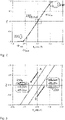
- Fig. 3 shows an enlarged view of a portion of the reversible linear portion of the magnetization curve of Fig. 2 .
- the magnetization curve to the external magnetic field B extz is shifted towards higher magnetization values when the external magnetic field B extz is decreased from the nucleation field H nucl , compared to when the external magnetic field B extz is increased from the nucleation field H nucl .
- the reversible linear portion of the magnetization curve exhibits a hysteresis due to the different vortex core magnetization polarity, that is the direction of the vortex core 231 magnetization.
- the vortex core magnetization polarity depends on the nucleation field +/-H nucl at which the vortex re-forms after vortex expulsion. It is then possible to operate the magnetoresistive element 2 in only one of the branch of the magnetization curve, for example the branch A (see Fig. 3 ) when the field is swept back to negative from the positive nucleation field +H nucl (and the positive vortex expulsion field +H expl ) or the branch B when the field is swept back to positive from the negative nucleation field - H nucl (and the negative vortex expulsion field -H expl ).
- a method for operating the magnetoresistive element 2 can comprise the steps of selecting the direction z or -z of the vortex core magnetization (vortex core magnetization polarity) by applying an initialization magnetic field to the magnetoresistive element 2 until the vortex expulsion field H expl is reached and then, reducing the initialization magnetic field below the nucleation field H nucl at which the vortex re-forms.
- the vortex core magnetization polarity is determined by the polarity of the vortex expulsion field H expl and the nucleation field H nucl .
- the method further comprises the step of measuring an external magnetic field 60.
- the method can further comprise a step of programming the magnetoresistive element 2 to program the orientation of the reference magnetization 210.
- the programming step can be performed by applying a programming magnetic field adapted to orient the reference magnetization 210.
- the programming step can further comprise heating the magnetoresistive element 2 to a temperature where the orientation of the reference magnetization 210 is facilitated, for example at a temperature where the reference magnetization 210 is unpinned. Heating the magnetoresistive element 2 can be performed by using resistive heating or laser heating.
- the vortex core magnetization polarity can be considered fixed.
- the operation of the magnetoresistive element 2 is not limited to any specific portion of the branches A or B shown in Fig. 3 . Indeed, the magnetoresistive element 2 can be operated anywhere in the linear region of branch A or branch B (the latter with a vortex magnetization polarity reversed relative to the one in branch A).
- the magnetoresistive element 2 should measure the external magnetic field 60 below the vortex expulsion field +/-H expl .
- the vortex magnetization polarity is fixed during sensor operation and is independent of vortex chirality (clockwise or counterclockwise).
- Fig. 4 reports magnetization curves to the z-aligned external magnetic field B extz on the magnetization of the sense layer 23, for several thickness of the sense layer 23, namely for thicknesses of the sense layer 23 between 10 nm and 60 nm.
- the magnetoresistive element 2 has a lateral dimension D of about 250 nm.
- Fig. 4 shows an increase in the slope of the magnetization curve, and thus the susceptibility ⁇ , with increasing thickness of the sense layer 23. For a given TMR value, increasing the thicknesses of the sense layer 23 results in an increase of the sensitivity S of the magnetoresistive element 2. This is in contrast to the case of a vortex configuration in the the plane of the sense layer 23 and having a vortex core magnetization that is reversibly movable substantially parallel to the plane of the sense layer 23.
- Fig. 5 reports magnetization curves to the z-aligned external magnetic field B extz of the sense layer 23 for several thickness of the sense layer 23, namely for thicknesses of the sense layer 23 between 10 nm and 60 nm.
- the magnetoresistive element 2 has a lateral dimension of about 450 nm.
- Figs. 4 and 5 show that the susceptibility ⁇ increases, and for a given TMR value the sensitivity S of the magnetoresistive element 2 increases, with decreasing smaller lateral dimension D of the magnetoresistive element 2. For given thicknesses of the layers 21, 23, the value the sensitivity S increases with increasing the aspect ratio t/D of the thickness t to the diameter (lateral dimension) D of the magnetoresistive element 2.
- the sensitivity S of the magnetoresistive element 2 is plotted as a function of the thickness of the sense layer 23 in Fig. 6 .
- the sensitivity S was simulated for lateral dimensions D of the magnetoresistive element 2 of 150 nm, 200 nm and 250 nm, and for magnetizations of the sense layer 23 of 400 and 600 kA/m.
- the TMR value of the magnetoresistive element 2 was assumed to be 100%.
- Fig. 6 shows that the higher values of sensitivity S are obtained for a lateral dimension of 150 nm and a magnetization of 400 kA/m.
- decreasing the sense magnetization 230 of the sense layer 23 results in an increase of the sensitivity S of the magnetoresistive element 2.
- the expression "sense magnetization” is used indifferently for "saturation sense magnetization” or “spontaneous sense magnetization", where saturation magnetization has its usual meaning of the maximum induced magnetic moment.
- the results shown above suggest providing the magnetoresistive element 2 where the reference layer 21 has a reference magnetization 210 oriented substantially perpendicular to the plane of the reference layer 21, and where the sense layer 23 has a sense magnetization 230 comprising a vortex configuration in the absence of an external magnetic field 60.
- the vortex configuration should be substantially parallel to the plane of the sense layer 23 and have a vortex core 231 magnetization along an out-of-plane axis 50 substantially perpendicular to the plane of the sense layer 23.
- the magnetoresistive element 2 should have small lateral dimension D (or high aspect ratio), for example a lateral dimension D below 300 nm, preferably below 250 nm, or preferably below 150 nm, and a small sense magnetization 230 of the sense layer 23, for example a sense magnetization below 850 kA/m, possibly below 600 kA/m or possibly below 400 kA/M.
- the sense layer 23 has a thickness of that is greater than 50 nm or preferably greater than 100 nm.
- the thickness of the sense layer 23 can be thick (more than 50 nm) and the sense magnetization 230 of the sense layer 23 can have value that is corresponds to typical saturation magnetization values found in conventional magnetoresistive elements (for example 600 kA/m or larger).
- the magnetoresistive element 2 has a lateral dimension D of 250 nm and the sense layer 23 has a thickness of 110 nm.
- the ferromagnetic material forming the sense layer 23 can comprise a ferromagnetic alloy having a sense magnetization of 600 kA/m or larger (here 600 kA/m).
- the low sense magnetization of the sense layer 23 can be obtained by decreasing the thickness (for example below 50 nm) and/or by a proper selection of the ferromagnetic material forming the sense layer 23 such as to obtain a low sense magnetization (for example lower than 600 kA/m).
- the magnetoresistive element 2 has a lateral dimension D of 250 nm
- the sense layer 23 has a thickness of 46 nm and has a sense magnetization of 400 kA/m.
- the sense layer 23 can be formed a ferromagnetic alloy having a low magnetization.
- Figs. 7 and 8 show that a substantially identical magnetization curve is obtained for the magnetoresistive element 2 of the first and second examples.
- the expulsion field H expl can be about 300 mT and the nucleation field H nucl can be about 200 mT.
- the reference layer 21 can comprise a synthetic antiferromagnetic (SAF) structure including a first reference sublayer 211 in contact with the tunnel barrier layer 22 and a second reference sublayer 212 separated from the first reference sublayer 211 by a coupling layer 213, wherein the coupling layer 213 antiferromagnetically couple the first reference sublayer 211 to the second reference sublayer 212.
- SAF synthetic antiferromagnetic
- Each of the first and second reference sublayer 211, 212 has PMA such that a reference magnetization 210 is oriented substantially perpendicular to the plane of the first and second reference sublayer 211, 212 and in opposite directions.
- each of the first and second reference sublayer 211, 212 includes a multilayer structure.
- each of the first and second reference sublayer 211, 212 can include a plurality of alternating first metallic layers 201 and second metallic layers 202.
- the first metallic layer 201 can comprise an ultrathin Co layer and the second metallic layer 202 can comprise an ultrathin Pt layer.
- the second metallic layer 202 preferably comprises Pt, other metals that provide PMA can also be used.
- the ultrathin Co layer 201 can have a thickness between 0.4 nm and 0.6 nm.
- the ultrathin Pt layer 202 can have a thickness between 0.2 nm and 0.4 nm.
- the coupling layer 213 can be a Ru layer. Although the coupling layer 213 preferably comprises Ru, other metals that generate RKKY coupling can also be used.
- the reference layer 21 comprising the SAF structure according to the configuration of Fig. 9 can achieve a field stability of greater than 300 mT to 400 mT.
Landscapes
- Engineering & Computer Science (AREA)
- Power Engineering (AREA)
- Physics & Mathematics (AREA)
- Chemical & Material Sciences (AREA)
- Crystallography & Structural Chemistry (AREA)
- Condensed Matter Physics & Semiconductors (AREA)
- General Physics & Mathematics (AREA)
- Hall/Mr Elements (AREA)
- Measuring Magnetic Variables (AREA)
Abstract
Description
- The present invention concerns a magnetoresistive element comprising a sense layer, for measuring an external magnetic field along an axis substantially perpendicular to the plane of the sense layer. The present invention further concerns a method for operating the magnetoresistive element.
- Currently, magnetic sensors are widely used in cell phones and other mobile devices as electronic compass. For a two-dimensional magnetic field in an X-Y plane, measurement of the X and Y components of the magnetic field within the plane may be implemented by using two orthogonal sensors, but for the measurement on the magnetic field in a Z-axis direction there are many difficulties. The following solutions are typically utilized.
- One solution includes a separate single-axis planar magnetoresistive sensor installed perpendicular to a two-axis planar sensor. This solution requires assembling two different sensors, the X-Y two-axis magnetoresistive sensor and the Z-axis magnetoresistive sensor.
- Another solution includes a flux guide to convert a magnetic field from the Z-axis direction into magnetic field components in the X- and Y-axis directions. For example, document
US2012206137 discloses a single-chip three-axis AMR sensor, which implements measurement of a magnetic field in the Z-axis direction by placing a flux guide above in-plane sensors. In such solution, the magnetic field in the Z-axis direction is not fully converted into the X- and Y-axis directions. In addition, such sensor design needs to use a specific algorithm for calculating the magnetic field in the Z-axis direction, which makes the sensor design more complicated. - Yet another solution includes micro-machining a substrate to form an inclined plane, onto which a sensor that partially senses the magnetic field in the Z-axis direction is deposited. Such a process is very complicated, has a low spatial efficiency, and may cause some shadowing effects in the deposition of the sensor, which may degrade the performance of the sensor.
- Yet another solution includes using magnetic materials with perpendicular magnetic anisotropy for measuring the magnetic field in the Z-axis direction. For example, document
US20130168787 discloses a magnetic sensor which measures a Z-axis component of an external magnetic field by using a perpendicular magnetic anisotropy material. The perpendicular magnetic anisotropy material has a high coercivity, and low magnetoresistance. - The present disclosure concerns a magnetoresistive element comprising a reference layer having a fixed reference magnetization, a sense layer having a free sense magnetization and a tunnel barrier layer between the reference and sense layers. The magnetoresistive element is configured to measure an external magnetic field oriented substantially perpendicular to the plane of the layers. The reference magnetization is oriented substantially perpendicular to the plane of the reference layer. The sense magnetization comprising a vortex configuration in the absence of an external magnetic field. The vortex configuration is substantially parallel to the plane of the sense layer and has a vortex core magnetization direction along an out-of-plane axis substantially perpendicular to the plane of the sense layer.
- The present disclosure further concerns a method for operating the magnetoresistive element, comprising:
- selecting the direction of the a vortex core by applying an initialization magnetic field until the vortex expulsion field is reached and reducing the initialization magnetic field below a nucleation field at which vortex re-forms; wherein the vortex core magnetization direction is determined by the polarity of the vortex expulsion field and the nucleation field; and
- measuring an external magnetic field.
- The magnetoresistive element disclosed herein can measure an external magnetic field along an out-of-plane axis substantially perpendicular to the plane of the sense layer. The vortex configuration of the magnetoresistive element can have an expulsion field greater than 200 mT or 250 mT.
- The magnetoresistive element has low hysteresis, less than 300 µV/V for external magnetic field magnitudes up to the expulsion field, and high linearity, i.e., less than 2% or 1% error.
- Exemplar embodiments of the invention are disclosed in the description and illustrated by the drawings in which:
-
Fig. 1 illustrates a magnetoresistive element, according to an embodiment; -
Fig. 2 shows a magnetization curve of the magnetoresistive element; -
Fig. 3 shows an enlarged view of a portion of the reversible linear portion of the magnetization curve ofFig. 2 ; -
Fig. 4 report magnetization curves for several thickness of the sense layer and for the magnetoresistive element having a lateral dimension of 250 nm; -
Fig. 5 report magnetization curves for several thickness of the sense layer and for the magnetoresistive element having a lateral dimension of 450 nm; -
Fig. 6 reports the sensitivity of the magnetoresistive element as a function of the thickness of the sense layer; -
Fig. 7 shows the magnetization curve for the magnetoresistive element having a lateral dimension of 250 nm, a sense layer having a thickness of 110 nm and a magnetic moment of 600 kA/m; -
Fig. 8 shows the magnetization curve for the magnetoresistive element having a lateral dimension of 250 nm, a sense layer having a thickness of 46 nm and a magnetic moment of 400 kA/m; and -
Fig. 9 illustrates a reference layer of the magnetoresistive element, according to an embodiment. -
Fig. 1 illustrates amagnetoresistive element 2, according to an embodiment, The magnetoresistive element comprises areference layer 21 having afixed reference magnetization 210, asense layer 23 having afree sense magnetization 230 and atunnel barrier layer 22 between thereference layer 21 and thesense layer 23. Thesense magnetization 230 comprises a vortex configuration substantially parallel to the plane of thesense layer 23 in the absence of an externalmagnetic field 60. Thereference layer 21 can have perpendicular magnetic anisotropy (PMA) such that thereference magnetization 210 is oriented substantially perpendicular to the plane of thereference layer 21. - The
magnetoresistive element 2 can measure an externalmagnetic field 60 being oriented substantially perpendicular to the plane of the reference andsense layers - The
sense layer 23 has asense magnetization 230 direction distribution with a vortex configuration, whereby the vortex magnetization curls in a circular path along the edge of thesense layer 23 and around avortex core 231. The vortex magnetization direction may be arranged in a clockwise direction and may also be arranged in a counterclockwise direction. During normal sensor operation, the magnetization of thevortex core 231 can vary in accordance to the externalmagnetic field 60 in a direction substantially perpendicular to the plane of the sense layer 23 (or direction ±z). Referring toFig. 1 , the magnetization of thevortex core 231 can be oriented in an upward direction (i.e., toward the direction +z) or in a downward direction (i.e., toward an opposite direction -z). The size of the vortex core increases or decreases in the direction +z or -z () when the magnitude of the externalmagnetic field 60 increases or decreases, respectively. However, during normal sensor operation the vortex core magnetization direction ±z, or vortex core magnetization polarity, is fixed. - The vortex configuration provides a linear and non-hysteretic behavior in a large magnitude range of the external
magnetic field 60, for practical size of themagnetoresistive element 2 and thickness of thesense layer 23. The linear and non-hysteretic portion of the magnetization curve facilitates the measurement of small variations of the externalmagnetic field 60. The vortex configuration is thus advantageous for magnetic sensor applications. -
Fig. 2 shows a magnetization curve (or hysteresis response) of the magnetoresistive element 2as a function of the external magnetic field 60 (indicated by the symbol Bextz). Here, "mz" corresponds to the averaged component along direction ±z of the sense magnetization (<Mz> or z-component of the sense magnetization Ms), normalized to the sense magnetization Ms (mz=<Mz>/Ms). In the case of a vortex configuration, the magnetization curve is characterized by a linear increase of the vortex core magnetization with the external magnetic field Bextz until the vortex expulsion field is reached at the Hexpl point. At this point thesense magnetization 230 becomes magnetically saturated (represented by the arrow pointing upwards (the direction +z). The vortex state in thesensing layer 23 is recovered when the external magnetic field Bextz is reduced below a nucleation field Hnucl. When the external magnetic field Bextz is decreased until the vortex expulsion field is reached at the Hexpl point (negative external magnetic field Bext) thesense magnetization 230 becomes magnetically saturated (represented by the arrow pointing downwards (the direction -z). The nucleation field Hnucl is the field at which vortex re-forms after vortex expulsion. As long as the magnitude of the external magnetic field Bextz is below the absolute value corresponding to the expulsion field (+/-Hexpl), the magnetization curve comprises a reversible linear portion corresponding to the variation of thevortex core 231 magnetization with the externalmagnetic field 60. The vortex core magnetization polarity can be reversed (between direction z and -z) when the expulsion field Hexpl is exceeded. -
Fig. 3 shows an enlarged view of a portion of the reversible linear portion of the magnetization curve ofFig. 2 . The magnetization curve to the external magnetic field Bextz is shifted towards higher magnetization values when the external magnetic field Bextz is decreased from the nucleation field Hnucl, compared to when the external magnetic field Bextz is increased from the nucleation field Hnucl. In other words, the reversible linear portion of the magnetization curve exhibits a hysteresis due to the different vortex core magnetization polarity, that is the direction of thevortex core 231 magnetization. - The vortex core magnetization polarity depends on the nucleation field +/-Hnucl at which the vortex re-forms after vortex expulsion. It is then possible to operate the
magnetoresistive element 2 in only one of the branch of the magnetization curve, for example the branch A (seeFig. 3 ) when the field is swept back to negative from the positive nucleation field +Hnucl (and the positive vortex expulsion field +Hexpl) or the branch B when the field is swept back to positive from the negative nucleation field - Hnucl (and the negative vortex expulsion field -Hexpl). - A method for operating the
magnetoresistive element 2 can comprise the steps of selecting the direction z or -z of the vortex core magnetization (vortex core magnetization polarity) by applying an initialization magnetic field to themagnetoresistive element 2 until the vortex expulsion field Hexpl is reached and then, reducing the initialization magnetic field below the nucleation field Hnucl at which the vortex re-forms. The vortex core magnetization polarity is determined by the polarity of the vortex expulsion field Hexpl and the nucleation field Hnucl. The method further comprises the step of measuring an externalmagnetic field 60. - After applying an initialization magnetic field, the method can further comprise a step of programming the
magnetoresistive element 2 to program the orientation of thereference magnetization 210. The programming step can be performed by applying a programming magnetic field adapted to orient thereference magnetization 210. The programming step can further comprise heating themagnetoresistive element 2 to a temperature where the orientation of thereference magnetization 210 is facilitated, for example at a temperature where thereference magnetization 210 is unpinned. Heating themagnetoresistive element 2 can be performed by using resistive heating or laser heating. During the programming step, the vortex core magnetization polarity can be considered fixed. - It should be noted that the operation of the
magnetoresistive element 2 is not limited to any specific portion of the branches A or B shown inFig. 3 . Indeed, themagnetoresistive element 2 can be operated anywhere in the linear region of branch A or branch B (the latter with a vortex magnetization polarity reversed relative to the one in branch A). - In any case, the
magnetoresistive element 2 should measure the externalmagnetic field 60 below the vortex expulsion field +/-Hexpl. The vortex magnetization polarity is fixed during sensor operation and is independent of vortex chirality (clockwise or counterclockwise). - The obtention of a vortex configuration in the
sense layer 23 depends on a number of factors, including materials properties of thesense layer 23. Generally, the vortex configuration is favored at zero applied field by increasing the aspect ratio of the thickness on the diameter of thesense layer 23. The aspect ratio is still typically much less than 1 (for example 0.01 to 0.5). Moreover, the values and the slope of the linear part of the magnetization curve ofFig. 2 are strongly dependent on the size of thesense layer 23. - In particular, the vortex configuration can be characterized by its susceptibility χ, which corresponds to the slope of the linear region of the magnetization curve:

- The sensitivity S of the
magnetoresistive element 2 is then proportional to the product between the susceptibility χ and the tunnel magnetoresistance (TMR) of the magnetoresistive sensor element 2:
-
Fig. 4 reports magnetization curves to the z-aligned external magnetic field Bextz on the magnetization of thesense layer 23, for several thickness of thesense layer 23, namely for thicknesses of thesense layer 23 between 10 nm and 60 nm. Themagnetoresistive element 2 has a lateral dimension D of about 250 nm.Fig. 4 shows an increase in the slope of the magnetization curve, and thus the susceptibility χ, with increasing thickness of thesense layer 23. For a given TMR value, increasing the thicknesses of thesense layer 23 results in an increase of the sensitivity S of themagnetoresistive element 2. This is in contrast to the case of a vortex configuration in the the plane of thesense layer 23 and having a vortex core magnetization that is reversibly movable substantially parallel to the plane of thesense layer 23. -
Fig. 5 reports magnetization curves to the z-aligned external magnetic field Bextz of thesense layer 23 for several thickness of thesense layer 23, namely for thicknesses of thesense layer 23 between 10 nm and 60 nm. Themagnetoresistive element 2 has a lateral dimension of about 450 nm.Figs. 4 and 5 show that the susceptibility χ increases, and for a given TMR value the sensitivity S of themagnetoresistive element 2 increases, with decreasing smaller lateral dimension D of themagnetoresistive element 2. For given thicknesses of thelayers magnetoresistive element 2. - The sensitivity S of the
magnetoresistive element 2 is plotted as a function of the thickness of thesense layer 23 inFig. 6 . The sensitivity S was simulated for lateral dimensions D of themagnetoresistive element 2 of 150 nm, 200 nm and 250 nm, and for magnetizations of thesense layer 23 of 400 and 600 kA/m. The TMR value of themagnetoresistive element 2 was assumed to be 100%.Fig. 6 shows that the higher values of sensitivity S are obtained for a lateral dimension of 150 nm and a magnetization of 400 kA/m. For a given TMR value, decreasing thesense magnetization 230 of thesense layer 23 results in an increase of the sensitivity S of themagnetoresistive element 2. In the whole text of this application, the expression "sense magnetization" is used indifferently for "saturation sense magnetization" or "spontaneous sense magnetization", where saturation magnetization has its usual meaning of the maximum induced magnetic moment. - In term of design rules for the
magnetoresistive element 2 that can measure an external magnetic field along an out-of-plane axis substantially perpendicular to the plane of the sense layer and having high working field range, low hysteresis, high linearity and sufficient sensitivity, the results shown above suggest providing themagnetoresistive element 2 where thereference layer 21 has areference magnetization 210 oriented substantially perpendicular to the plane of thereference layer 21, and where thesense layer 23 has asense magnetization 230 comprising a vortex configuration in the absence of an externalmagnetic field 60. The vortex configuration should be substantially parallel to the plane of thesense layer 23 and have avortex core 231 magnetization along an out-of-plane axis 50 substantially perpendicular to the plane of thesense layer 23. - Moreover, in term of design rules for the
magnetoresistive element 2 having high working field range (such as 60 mT or more), low hysteresis (such as less than 300 µV/V) for external magnetic field magnitudes up to the expulsion field, high linearity (such as less than 2% or 1% error) and sufficient sensitivity, themagnetoresistive element 2 should have small lateral dimension D (or high aspect ratio), for example a lateral dimension D below 300 nm, preferably below 250 nm, or preferably below 150 nm, and asmall sense magnetization 230 of thesense layer 23, for example a sense magnetization below 850 kA/m, possibly below 600 kA/m or possibly below 400 kA/M. Advantageously, thesense layer 23 has a thickness of that is greater than 50 nm or preferably greater than 100 nm. - In one aspect, the thickness of the
sense layer 23 can be thick (more than 50 nm) and thesense magnetization 230 of thesense layer 23 can have value that is corresponds to typical saturation magnetization values found in conventional magnetoresistive elements (for example 600 kA/m or larger). In a first example (Fig. 7 ), themagnetoresistive element 2 has a lateral dimension D of 250 nm and thesense layer 23 has a thickness of 110 nm. The ferromagnetic material forming thesense layer 23 can comprise a ferromagnetic alloy having a sense magnetization of 600 kA/m or larger (here 600 kA/m). - In another aspect, the low sense magnetization of the
sense layer 23 can be obtained by decreasing the thickness (for example below 50 nm) and/or by a proper selection of the ferromagnetic material forming thesense layer 23 such as to obtain a low sense magnetization (for example lower than 600 kA/m). In a second example (Fig. 8 ), themagnetoresistive element 2 has a lateral dimension D of 250 nm, thesense layer 23 has a thickness of 46 nm and has a sense magnetization of 400 kA/m. Thesense layer 23 can be formed a ferromagnetic alloy having a low magnetization. -
Figs. 7 and8 show that a substantially identical magnetization curve is obtained for themagnetoresistive element 2 of the first and second examples. In both examples, the expulsion field Hexpl can be about 300 mT and the nucleation field Hnucl can be about 200 mT. - The
magnetoresistive element 2 can have a sensitivity S of 1 mV/V or higher, for TMR = 100%. The sensitivity S can be further increased by increasing TMR. - Referring again to
Fig. 1 , thereference layer 21 can comprise a synthetic antiferromagnetic (SAF) structure including afirst reference sublayer 211 in contact with thetunnel barrier layer 22 and asecond reference sublayer 212 separated from thefirst reference sublayer 211 by acoupling layer 213, wherein thecoupling layer 213 antiferromagnetically couple thefirst reference sublayer 211 to thesecond reference sublayer 212. Each of the first andsecond reference sublayer reference magnetization 210 is oriented substantially perpendicular to the plane of the first andsecond reference sublayer - In an embodiment represented in
Fig. 9 , each of the first andsecond reference sublayer second reference sublayer metallic layers 201 and second metallic layers 202. For example, the firstmetallic layer 201 can comprise an ultrathin Co layer and the secondmetallic layer 202 can comprise an ultrathin Pt layer. Although the secondmetallic layer 202 preferably comprises Pt, other metals that provide PMA can also be used. - In one aspect, the
ultrathin Co layer 201 can have a thickness between 0.4 nm and 0.6 nm. Theultrathin Pt layer 202 can have a thickness between 0.2 nm and 0.4 nm. Thecoupling layer 213 can be a Ru layer. Although thecoupling layer 213 preferably comprises Ru, other metals that generate RKKY coupling can also be used. - The
reference layer 21 comprising the SAF structure according to the configuration ofFig. 9 can achieve a field stability of greater than 300 mT to 400 mT. -
- 2
- magnetoresistive element
- 21
- reference layer
- 201
- first metallic layer
- 202
- second metallic layer
- 210
- reference magnetization
- 211
- first reference sublayer
- 212
- second reference sublayer
- 213
- coupling layer
- 22
- tunnel barrier layer
- 23
- sense layer
- 230
- sense magnetization
- 231
- vortex core
- 50
- out-of-plane axis
- 60
- external magnetic field
- A, B
- branch of the magnetization curve
- Bextz
- external magnetic field along direction z
- D
- lateral dimension, diameter
- Hexpl
- expulsion field
- Hnucl
- nucleation field
- mz
- magnetization
- t
- thickness
Claims (14)
- Magnetoresistive element (2) comprising a reference layer (21) having a fixed reference magnetization (210), a sense layer (23) having a free sense magnetization (230) and a tunnel barrier layer (22) between the reference layer (21) and the sense layer (23); the magnetoresistive element (2) being configured to measure an external magnetic field (60) oriented substantially perpendicular to the plane of the layers (21, 23);
wherein the reference magnetization (210) is oriented substantially perpendicular to the plane of the reference layer (21); and
wherein the sense magnetization (230) comprises a vortex configuration in the absence of an external magnetic field (60), the vortex configuration being substantially parallel to the plane of the sense layer (23) and having a vortex core (231) magnetization along an out-of-plane axis (50) substantially perpendicular to the plane of the sense layer (23). - Magnetoresistive element according to claim 1,
having a lateral dimension being smaller than 450 nm. - Magnetoresistive element according to claim 2,
having a lateral dimension being smaller than 300 nm, 250 nm or 150 nm. - Magnetoresistive element according to any one of claims 1 to 3,
wherein the sense layer (23) has a thickness being greater than 50 nm. - Magnetoresistive element according to claim 4,
wherein the sense layer (23) has a thickness being greater than 100 nm. - Magnetoresistive element according to any one of claims 1 to 5,
wherein the sense magnetization (230) is smaller than 850 kA/m at room temperature. - Magnetoresistive element according to claim 6,
wherein the sense magnetization (230) is between 400 kA/m and 600 kA/m at room temperature. - Magnetoresistive element according to any one of claims 1 to 7,
wherein the reference layer (21) comprises a synthetic antiferromagnetic (SAF) structure including a first reference sublayer (211) in contact with the tunnel barrier layer (22) and a second reference sublayer (212) separated from the first reference sublayer (211) by a coupling layer (213) antiferromagnetically coupling the first reference sublayer (211) to the second reference sublayer (212). - Magnetoresistive element according to claim 8,
wherein each of the first and second reference sublayer (211, 212) comprises a plurality of alternating first metallic layers (201) and second metallic layers (202). - Magnetoresistive element according to claim 9,
wherein the first metallic layer (201) has a thickness between 0.4 nm and 0.6 nm and the second metallic layer (202) has a thickness between 0.2 nm and 0.4 nm and the second metallic layer (202). - Magnetoresistive element according to any one of claims 1 to 10,
configured such that the vortex configuration has an expulsion field greater than 200 mT or 250 mT. - Magnetoresistive element according to any one of claims 1 to 11,
having a linearity less than 2%. - Method for operating the magnetoresistive element (2) according any one of claims 1 to 12, comprising:selecting the direction (z, -z) of the vortex core magnetization by applying an initialization magnetic field until a vortex expulsion field (Hexpl) is reached and reducing the initialization magnetic field below a nucleation field (Hnucl) at which vortex re-forms;
wherein the vortex core direction (z, -z) is determined by the polarity of the vortex expulsion field (Hexpl) and the nucleation field (Hnucl); andmeasuring an external magnetic field (60). - Method according to claim 13,
wherein said measuring an external magnetic field (60) is performed for external magnetic field (60) below the vortex expulsion field (Hexpl).
Priority Applications (5)
| Application Number | Priority Date | Filing Date | Title |
|---|---|---|---|
| EP20315489.3A EP4012431A1 (en) | 2020-12-11 | 2020-12-11 | Magnetoresistive element for sensing a magnetic field in a z-axis |
| PCT/IB2021/061484 WO2022123472A1 (en) | 2020-12-11 | 2021-12-09 | Magnetoresistive element for sensing a magnetic field in a z-axis |
| JP2023535328A JP2023553931A (en) | 2020-12-11 | 2021-12-09 | Magnetoresistive element that detects the magnetic field on the Z-axis |
| US18/256,494 US20240027551A1 (en) | 2020-12-11 | 2021-12-09 | Magnetoresistive element for sensing a magnetic field in a z-axis |
| KR1020237019328A KR20230117352A (en) | 2020-12-11 | 2021-12-09 | Magnetoresistive element for sensing the magnetic field in the Z axis |
Applications Claiming Priority (1)
| Application Number | Priority Date | Filing Date | Title |
|---|---|---|---|
| EP20315489.3A EP4012431A1 (en) | 2020-12-11 | 2020-12-11 | Magnetoresistive element for sensing a magnetic field in a z-axis |
Publications (1)
| Publication Number | Publication Date |
|---|---|
| EP4012431A1 true EP4012431A1 (en) | 2022-06-15 |
Family
ID=74187108
Family Applications (1)
| Application Number | Title | Priority Date | Filing Date |
|---|---|---|---|
| EP20315489.3A Pending EP4012431A1 (en) | 2020-12-11 | 2020-12-11 | Magnetoresistive element for sensing a magnetic field in a z-axis |
Country Status (5)
| Country | Link |
|---|---|
| US (1) | US20240027551A1 (en) |
| EP (1) | EP4012431A1 (en) |
| JP (1) | JP2023553931A (en) |
| KR (1) | KR20230117352A (en) |
| WO (1) | WO2022123472A1 (en) |
Cited By (2)
| Publication number | Priority date | Publication date | Assignee | Title |
|---|---|---|---|---|
| EP4257998A1 (en) * | 2022-04-05 | 2023-10-11 | Commissariat à l'énergie atomique et aux énergies alternatives | Magnetorestistive sensor sensitive to an out-of-plane magnetic field |
| EP4417989A1 (en) | 2023-02-17 | 2024-08-21 | Allegro MicroSystems, LLC | Magnetoresistive element having an out-of-plane sensitivity axis and having reduced hysteresis and increased working field range |
Citations (5)
| Publication number | Priority date | Publication date | Assignee | Title |
|---|---|---|---|---|
| US20110102939A1 (en) * | 2008-07-14 | 2011-05-05 | Fuji Electric Holdings Co., Ltd. | Spin valve element, method of driving the same, and storage device using the same |
| US20120206137A1 (en) | 2011-02-14 | 2012-08-16 | Memsic, Inc. | Monolithic tri-axis amr sensor and manufacturing method thereof |
| US20130168787A1 (en) | 2011-12-28 | 2013-07-04 | Industrial Technology Research Institute | Magnetic sensor |
| WO2013180277A1 (en) * | 2012-05-31 | 2013-12-05 | 国立大学法人九州大学 | Oscillator |
| EP3726237A2 (en) * | 2019-04-18 | 2020-10-21 | Nxp B.V. | Magnetic field sensor, system, and method for speed measurement |
-
2020
- 2020-12-11 EP EP20315489.3A patent/EP4012431A1/en active Pending
-
2021
- 2021-12-09 KR KR1020237019328A patent/KR20230117352A/en unknown
- 2021-12-09 US US18/256,494 patent/US20240027551A1/en active Pending
- 2021-12-09 WO PCT/IB2021/061484 patent/WO2022123472A1/en active Application Filing
- 2021-12-09 JP JP2023535328A patent/JP2023553931A/en active Pending
Patent Citations (5)
| Publication number | Priority date | Publication date | Assignee | Title |
|---|---|---|---|---|
| US20110102939A1 (en) * | 2008-07-14 | 2011-05-05 | Fuji Electric Holdings Co., Ltd. | Spin valve element, method of driving the same, and storage device using the same |
| US20120206137A1 (en) | 2011-02-14 | 2012-08-16 | Memsic, Inc. | Monolithic tri-axis amr sensor and manufacturing method thereof |
| US20130168787A1 (en) | 2011-12-28 | 2013-07-04 | Industrial Technology Research Institute | Magnetic sensor |
| WO2013180277A1 (en) * | 2012-05-31 | 2013-12-05 | 国立大学法人九州大学 | Oscillator |
| EP3726237A2 (en) * | 2019-04-18 | 2020-10-21 | Nxp B.V. | Magnetic field sensor, system, and method for speed measurement |
Non-Patent Citations (1)
| Title |
|---|
| RAHMAN N ET AL: "Thickness dependence of magnetization dynamics of an in-plane anisotropy ferromagnet under a crossed spin torque polarizer", JOURNAL OF MAGNETISM AND MAGNETIC MATERIALS, ELSEVIER, AMSTERDAM, NL, vol. 439, 8 May 2017 (2017-05-08), pages 95 - 100, XP085050054, ISSN: 0304-8853, DOI: 10.1016/J.JMMM.2017.05.016 * |
Cited By (4)
| Publication number | Priority date | Publication date | Assignee | Title |
|---|---|---|---|---|
| EP4257998A1 (en) * | 2022-04-05 | 2023-10-11 | Commissariat à l'énergie atomique et aux énergies alternatives | Magnetorestistive sensor sensitive to an out-of-plane magnetic field |
| WO2023194346A1 (en) * | 2022-04-05 | 2023-10-12 | Commissariat A L'energie Atomique Et Aux Energies Alternatives | Magnetorestistive sensor sensitive to an out-of-plane magnetic field |
| EP4417989A1 (en) | 2023-02-17 | 2024-08-21 | Allegro MicroSystems, LLC | Magnetoresistive element having an out-of-plane sensitivity axis and having reduced hysteresis and increased working field range |
| WO2024171048A1 (en) | 2023-02-17 | 2024-08-22 | Allegro Microsystems, Llc | Magnetoresistive element having an out-of-plane sensitivity axis and having reduced hysteresis and increased working field range |
Also Published As
| Publication number | Publication date |
|---|---|
| KR20230117352A (en) | 2023-08-08 |
| US20240027551A1 (en) | 2024-01-25 |
| WO2022123472A1 (en) | 2022-06-16 |
| JP2023553931A (en) | 2023-12-26 |
Similar Documents
| Publication | Publication Date | Title |
|---|---|---|
| EP3223028B1 (en) | Multiple axis magnetic sensor | |
| US9069033B2 (en) | 3-axis magnetic field sensor, method for fabricating magnetic field sensing structure and magnetic field sensing circuit | |
| EP3208626B1 (en) | Magnetic field sensor with skewed sense magnetization of sense layer | |
| EP3229035B1 (en) | Magnetic field sensor with permanent magnet biasing | |
| CN107976644B (en) | Magnetic field detection device | |
| US20210382123A1 (en) | Magneto-resistive element and magnetic sensor | |
| US9897667B2 (en) | Magnetic field sensor with permanent magnet biasing | |
| Ota et al. | CoFeB/MgO-based magnetic tunnel junction directly formed on a flexible substrate | |
| JPWO2015033464A1 (en) | Magnetic sensor element | |
| US20240027551A1 (en) | Magnetoresistive element for sensing a magnetic field in a z-axis | |
| EP3236276B1 (en) | Magnetic field sensor with multiple axis sense capability | |
| TW201327956A (en) | Magnetic sensor | |
| Han et al. | High-sensitivity tunnel magnetoresistance sensors based on double indirect and direct exchange coupling effect | |
| TWI518330B (en) | Inertial sensor | |
| Zhao et al. | L10-MnGa based magnetic tunnel junction for high magnetic field sensor | |
| CN106104828B (en) | Magnetic sensor | |
| Honkura et al. | The development of a micro-coil-on-ASIC type GSR sensor driven by GHz pulse current | |
| Ji et al. | Novel modeling and dynamic simulation of magnetic tunnel junctions for spintronic sensor development | |
| Ogasawara et al. | Effects of annealing temperature on sensing properties of magnetic-tunnel-junction-based sensors with perpendicular synthetic antiferromagnetic Co/Pt pinned layer | |
| US20240310461A1 (en) | Magnetoresistive sensor having a shielding element with vortex magnetization | |
| US11921172B2 (en) | Magnetoresistive sensor element with synthetic antiferromagnet biasing | |
| EP4417989A1 (en) | Magnetoresistive element having an out-of-plane sensitivity axis and having reduced hysteresis and increased working field range | |
| Qixing et al. | Research on the Z-axis Magnetic Sensor Based on the Giant Magnetoresistance Effect | |
| JP2006019484A (en) | Magnetometric sensor | |
| Jiang et al. | A Method of Forming Full-Wheatstone Bridge for Linear TMR Magnetic Sensors |
Legal Events
| Date | Code | Title | Description |
|---|---|---|---|
| PUAI | Public reference made under article 153(3) epc to a published international application that has entered the european phase |
Free format text: ORIGINAL CODE: 0009012 |
|
| STAA | Information on the status of an ep patent application or granted ep patent |
Free format text: STATUS: THE APPLICATION HAS BEEN PUBLISHED |
|
| AK | Designated contracting states |
Kind code of ref document: A1 Designated state(s): AL AT BE BG CH CY CZ DE DK EE ES FI FR GB GR HR HU IE IS IT LI LT LU LV MC MK MT NL NO PL PT RO RS SE SI SK SM TR |
|
| STAA | Information on the status of an ep patent application or granted ep patent |
Free format text: STATUS: REQUEST FOR EXAMINATION WAS MADE |
|
| 17P | Request for examination filed |
Effective date: 20221108 |
|
| RBV | Designated contracting states (corrected) |
Designated state(s): AL AT BE BG CH CY CZ DE DK EE ES FI FR GB GR HR HU IE IS IT LI LT LU LV MC MK MT NL NO PL PT RO RS SE SI SK SM TR |
|
| RAP3 | Party data changed (applicant data changed or rights of an application transferred) |
Owner name: CROCUS TECHNOLOGY SA |
|
| RAP1 | Party data changed (applicant data changed or rights of an application transferred) |
Owner name: ALLEGRO MICROSYSTEMS, LLC |
|
| RAP1 | Party data changed (applicant data changed or rights of an application transferred) |
Owner name: ALLEGRO MICROSYSTEMS, LLC |