EP4012293A1 - Refrigeration cycle device - Google Patents
Refrigeration cycle device Download PDFInfo
- Publication number
- EP4012293A1 EP4012293A1 EP19940618.2A EP19940618A EP4012293A1 EP 4012293 A1 EP4012293 A1 EP 4012293A1 EP 19940618 A EP19940618 A EP 19940618A EP 4012293 A1 EP4012293 A1 EP 4012293A1
- Authority
- EP
- European Patent Office
- Prior art keywords
- refrigerant
- heat exchanger
- compressor
- controller
- refrigeration cycle
- Prior art date
- Legal status (The legal status is an assumption and is not a legal conclusion. Google has not performed a legal analysis and makes no representation as to the accuracy of the status listed.)
- Granted
Links
Images










Classifications
-
- F—MECHANICAL ENGINEERING; LIGHTING; HEATING; WEAPONS; BLASTING
- F25—REFRIGERATION OR COOLING; COMBINED HEATING AND REFRIGERATION SYSTEMS; HEAT PUMP SYSTEMS; MANUFACTURE OR STORAGE OF ICE; LIQUEFACTION SOLIDIFICATION OF GASES
- F25B—REFRIGERATION MACHINES, PLANTS OR SYSTEMS; COMBINED HEATING AND REFRIGERATION SYSTEMS; HEAT PUMP SYSTEMS
- F25B41/00—Fluid-circulation arrangements
- F25B41/20—Disposition of valves, e.g. of on-off valves or flow control valves
-
- F—MECHANICAL ENGINEERING; LIGHTING; HEATING; WEAPONS; BLASTING
- F25—REFRIGERATION OR COOLING; COMBINED HEATING AND REFRIGERATION SYSTEMS; HEAT PUMP SYSTEMS; MANUFACTURE OR STORAGE OF ICE; LIQUEFACTION SOLIDIFICATION OF GASES
- F25B—REFRIGERATION MACHINES, PLANTS OR SYSTEMS; COMBINED HEATING AND REFRIGERATION SYSTEMS; HEAT PUMP SYSTEMS
- F25B2400/00—Component parts or details not otherwise provided for in this subclass
- F25B2400/04—Refrigeration circuit bypassing means
- F25B2400/0403—Refrigeration circuit bypassing means for condensers
-
- F—MECHANICAL ENGINEERING; LIGHTING; HEATING; WEAPONS; BLASTING
- F25—REFRIGERATION OR COOLING; COMBINED HEATING AND REFRIGERATION SYSTEMS; HEAT PUMP SYSTEMS; MANUFACTURE OR STORAGE OF ICE; LIQUEFACTION SOLIDIFICATION OF GASES
- F25B—REFRIGERATION MACHINES, PLANTS OR SYSTEMS; COMBINED HEATING AND REFRIGERATION SYSTEMS; HEAT PUMP SYSTEMS
- F25B2400/00—Component parts or details not otherwise provided for in this subclass
- F25B2400/04—Refrigeration circuit bypassing means
- F25B2400/0411—Refrigeration circuit bypassing means for expansion valves or capillary tubes
-
- F—MECHANICAL ENGINEERING; LIGHTING; HEATING; WEAPONS; BLASTING
- F25—REFRIGERATION OR COOLING; COMBINED HEATING AND REFRIGERATION SYSTEMS; HEAT PUMP SYSTEMS; MANUFACTURE OR STORAGE OF ICE; LIQUEFACTION SOLIDIFICATION OF GASES
- F25B—REFRIGERATION MACHINES, PLANTS OR SYSTEMS; COMBINED HEATING AND REFRIGERATION SYSTEMS; HEAT PUMP SYSTEMS
- F25B2500/00—Problems to be solved
- F25B2500/07—Exceeding a certain pressure value in a refrigeration component or cycle
-
- F—MECHANICAL ENGINEERING; LIGHTING; HEATING; WEAPONS; BLASTING
- F25—REFRIGERATION OR COOLING; COMBINED HEATING AND REFRIGERATION SYSTEMS; HEAT PUMP SYSTEMS; MANUFACTURE OR STORAGE OF ICE; LIQUEFACTION SOLIDIFICATION OF GASES
- F25B—REFRIGERATION MACHINES, PLANTS OR SYSTEMS; COMBINED HEATING AND REFRIGERATION SYSTEMS; HEAT PUMP SYSTEMS
- F25B2500/00—Problems to be solved
- F25B2500/26—Problems to be solved characterised by the startup of the refrigeration cycle
-
- F—MECHANICAL ENGINEERING; LIGHTING; HEATING; WEAPONS; BLASTING
- F25—REFRIGERATION OR COOLING; COMBINED HEATING AND REFRIGERATION SYSTEMS; HEAT PUMP SYSTEMS; MANUFACTURE OR STORAGE OF ICE; LIQUEFACTION SOLIDIFICATION OF GASES
- F25B—REFRIGERATION MACHINES, PLANTS OR SYSTEMS; COMBINED HEATING AND REFRIGERATION SYSTEMS; HEAT PUMP SYSTEMS
- F25B2600/00—Control issues
- F25B2600/01—Timing
-
- F—MECHANICAL ENGINEERING; LIGHTING; HEATING; WEAPONS; BLASTING
- F25—REFRIGERATION OR COOLING; COMBINED HEATING AND REFRIGERATION SYSTEMS; HEAT PUMP SYSTEMS; MANUFACTURE OR STORAGE OF ICE; LIQUEFACTION SOLIDIFICATION OF GASES
- F25B—REFRIGERATION MACHINES, PLANTS OR SYSTEMS; COMBINED HEATING AND REFRIGERATION SYSTEMS; HEAT PUMP SYSTEMS
- F25B2600/00—Control issues
- F25B2600/25—Control of valves
- F25B2600/2501—Bypass valves
-
- F—MECHANICAL ENGINEERING; LIGHTING; HEATING; WEAPONS; BLASTING
- F25—REFRIGERATION OR COOLING; COMBINED HEATING AND REFRIGERATION SYSTEMS; HEAT PUMP SYSTEMS; MANUFACTURE OR STORAGE OF ICE; LIQUEFACTION SOLIDIFICATION OF GASES
- F25B—REFRIGERATION MACHINES, PLANTS OR SYSTEMS; COMBINED HEATING AND REFRIGERATION SYSTEMS; HEAT PUMP SYSTEMS
- F25B2600/00—Control issues
- F25B2600/25—Control of valves
- F25B2600/2519—On-off valves
-
- F—MECHANICAL ENGINEERING; LIGHTING; HEATING; WEAPONS; BLASTING
- F25—REFRIGERATION OR COOLING; COMBINED HEATING AND REFRIGERATION SYSTEMS; HEAT PUMP SYSTEMS; MANUFACTURE OR STORAGE OF ICE; LIQUEFACTION SOLIDIFICATION OF GASES
- F25B—REFRIGERATION MACHINES, PLANTS OR SYSTEMS; COMBINED HEATING AND REFRIGERATION SYSTEMS; HEAT PUMP SYSTEMS
- F25B2700/00—Sensing or detecting of parameters; Sensors therefor
- F25B2700/21—Temperatures
- F25B2700/2117—Temperatures of an evaporator
- F25B2700/21175—Temperatures of an evaporator of the refrigerant at the outlet of the evaporator
Definitions
- the present invention relates to a refrigeration cycle apparatus.
- a refrigeration cycle apparatus has conventionally been known that has a function of suppressing reduction in pressure of refrigerant suctioned into a compressor at the start of the operation of the refrigeration cycle apparatus.
- PTL 1 Japanese Patent Laying-Open No. 2015-94558 discloses a heat pump system in which Hydro Fluoro Olefin (HFO) refrigerant is contained and a control valve is connected between a discharge port and a suction port of a compressor.
- HFO Hydro Fluoro Olefin
- the present invention has been made in order to solve the above-described problems, and an object of the present invention is to suppress reduction in pressure of refrigerant suctioned into a compressor at the start of the operation of a refrigeration cycle apparatus, irrespective of type of refrigerant.
- refrigerant circulates.
- the refrigeration cycle apparatus includes a compressor, a first heat exchanger, a second heat exchanger, an expansion valve, a flow rate adjuster, and a controller.
- the flow rate adjuster is configured to adjust an amount of refrigerant flowing per unit time through at least one of the first heat exchanger and the expansion valve.
- the controller is configured to switch an operation mode of the refrigeration cycle apparatus.
- the operation mode includes an activation mode and a normal mode. The activation mode is executed when the compressor is activated. The normal mode is executed after the activation mode.
- the refrigerant circulates in a first circulation direction in which the refrigerant flows sequentially through the compressor, the first heat exchanger, the expansion valve, and the second heat exchanger.
- the controller is configured to control the compressor and the flow rate adjuster to reduce the amount of refrigerant that flows per unit time through at least one of the first heat exchanger and the expansion valve in the activation mode to be less than the amount of refrigerant in the normal mode.
- the amount of refrigerant flowing per unit time through at least one of the first heat exchanger and the expansion valve in the activation mode is reduced to be less than the amount of refrigerant in the normal mode, and thereby, reduction in pressure of the refrigerant suctioned into the compressor at the start of the operation of the refrigeration cycle apparatus is suppressed irrespective of the type of refrigerant.
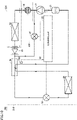
- Fig. 1 is a functional block diagram showing a configuration of a refrigeration cycle apparatus 100 according to the first embodiment together with a flow of refrigerant in a normal mode.
- the closed valve in Fig. 1 is shown in dotted pattern. The same also applies to Figs. 5 , 8 to 10 , 12 , and 13 , which will be described later.
- a refrigeration cycle apparatus 100 includes an outdoor unit 110 and an indoor unit 120.
- Indoor unit 120 is disposed in an indoor space.
- Outdoor unit 110 is disposed outside the indoor space (outdoors).
- Refrigerant including R290 is sealed in refrigeration cycle apparatus 100.
- Indoor unit 120 includes a condenser 2 (the first heat exchanger).
- Outdoor unit 110 includes a compressor 1, an expansion valve 3, an evaporator 4 (the second heat exchanger), a gas-liquid separator 5, a flow rate adjuster 130, a temperature sensor TS1, and a controller 10.
- Flow rate adjuster 130 has a solenoid valve 6 (the first valve) and a solenoid valve 7 (the second valve). Controller 10 may be included in indoor unit 120 or may be provided separately from outdoor unit 110 and indoor unit 120.
- the operation mode of refrigeration cycle apparatus 100 includes an activation mode and a normal mode.
- the activation mode is executed when compressor 1 is activated.
- the normal mode is executed subsequently to the activation mode.
- the normal mode may be executed after the activation mode, and another operation mode may be executed between the activation mode and the normal mode.
- the refrigerant circulates in a circulation direction (the first circulation direction) in which the refrigerant flows sequentially through compressor 1, condenser 2, expansion valve 3, and evaporator 4.
- Solenoid valve 6 is connected between a discharge port of compressor 1 and condenser 2.
- Solenoid valve 7 is connected between the discharge port of compressor 1 and a flow path extending between expansion valve 3 and evaporator 4.
- Gas-liquid separator 5 receives refrigerant from evaporator 4, separates the received refrigerant into refrigerant in a gas state (gas refrigerant) and refrigerant in a liquid state (liquid refrigerant), stores the liquid refrigerant therein, and guides the gas refrigerant to compressor 1.
- Gas-liquid separator 5 prevents the liquid refrigerant from being suctioned into compressor 1.
- Gas-liquid separator 5 includes an accumulator or a suction muffler.
- Controller 10 switches the operation mode of refrigeration cycle apparatus 100.
- controller 10 opens solenoid valve 6 and closes solenoid valve 7.
- controller 10 acquires a temperature T1 of the refrigerant flowing out of evaporator 4.
- Controller 10 controls a driving frequency F c of compressor 1, for example, to fall within a range of 50 Hz to 60 Hz, thereby controlling the amount of refrigerant discharged per unit time by compressor 1 such that the temperature in the indoor space reaches a target temperature (for example, a temperature set by a user).
- Controller 10 controls the degree of opening of expansion valve 3 such that the pressure difference between the refrigerant discharged from compressor 1 but not yet depressurized and the refrigerant depressurized but not yet suctioned into compressor 1 falls within a desired range of values.
- Expansion valve 3 may be controlled such that the degree of superheating and the degree of supercooling of the refrigerant reach their respective target values.
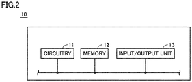
- Fig. 2 is a functional block diagram showing a configuration of controller 10 in Fig. 1 .
- controller 10 includes circuitry 11, a memory 12, and an input/output unit 13.
- Processing circuit 11 may be dedicated hardware or may be a central processing unit (CPU) that executes a program stored in memory 12.
- circuitry 11 is, for example, a single circuit, a composite circuit, a programmed processor, a parallel programmed processor, an application specific integrated circuit (ASIC), a field programmable gate array (FPGA), or a combination thereof.
- ASIC application specific integrated circuit
- FPGA field programmable gate array
- circuitry 11 is a CPU
- the function of controller 10 is implemented by software, firmware, or a combination of software and firmware.
- Software or firmware is described as a program and stored in memory 12.
- Memory 12 includes a nonvolatile or volatile semiconductor memory (for example, a random access memory (RAM), a read only memory (ROM), a flash memory, an erasable programmable read only memory (EPROM) or an electrically erasable programmable read only memory (EEPROM)), a magnetic disk, a flexible disk, an optical disk, a compact disk, a mini disk, or a digital versatile disc (DVD).
- RAM random access memory
- ROM read only memory
- EPROM erasable programmable read only memory
- EEPROM electrically erasable programmable read only memory
- the CPU is also referred to as a central processing unit, a processing unit, a computing unit, a microprocessor, a microcomputer, a processor, or a digital signal processor (DSP).
- DSP digital signal processor
- GWP total amount value T gwp is represented by the following equation (1) using: a GWP value R gwp as a physical property value specific to refrigerant; and a refrigerant amount M chg sealed in refrigeration cycle apparatus 100.
- GWP total amount value T gwp can be reduced by reducing refrigerant amount M chg sealed in the refrigeration cycle apparatus.
- refrigerant having a relatively low density needs to be used.
- refrigerant may be low-pressure refrigerant for which working pressure is relatively low.
- the low-pressure refrigerant includes R290 (propane) or R454a, for example.
- the heating performance of the refrigeration cycle apparatus is represented by the following equation (2) using: a refrigerant circulation amount Gr discharged per unit time by compressor 1; and an enthalpy difference ⁇ h representing the change in latent heat of the refrigerant in a condensation process.
- Refrigerant circulation amount Gr is represented by the following equation (3) using: a stroke volume Vst as the amount of refrigerant discharged per revolution by a compression mechanism of compressor 1; a density ⁇ s of refrigerant suctioned into compressor 1; and driving frequency F c of compressor 1.
- Enthalpy difference ⁇ h in the equation (2) differs for each refrigerant.
- refrigerant circulation amount Gr needs to be changed in order to change the refrigerant to low-pressure refrigerant for maintaining the heating performance of the refrigeration cycle apparatus.
- density ⁇ s of refrigerant is a physical property value specific to the refrigerant.
- Fig. 3 is a functional block diagram showing a configuration of a refrigeration cycle apparatus 900 according to a comparative example.
- Refrigeration cycle apparatus 900 has the same configuration as that of refrigeration cycle apparatus 100 in Fig. 1 except that refrigeration cycle apparatus 900 does not include solenoid valves 6 and 7 and includes a controller 90 in place of controller 10. The following describes problems occurring when the refrigerant circulating through refrigeration cycle apparatus 900 is changed from R32 to R290 while maintaining the heating performance of refrigeration cycle apparatus 900.
- Table 1 shows simulation results about the ratio of the value obtained when R290 is used to the value obtained when R32 is used, which is required for maintaining the heating performance when the refrigerant circulating through refrigeration cycle apparatus 900 in Fig. 3 is changed from R32 to R290.
- the above-mentioned values include values of the refrigerant amount, the refrigerant circulation amount, and the stroke volume.
- R32 is an example of refrigerant that has conventionally been used in refrigeration cycle apparatuses.
- [Table 1] Values Ratio of Value Obtained When R290 is Used to Value Obtained When R32 is Used (%) Refrigerant Amount 52 Refrigerant Circulation Amount 88 Stroke Volume 210
- the ratio of the refrigerant amount of R290 to the refrigerant amount of R32 is 52 % since R290 is lower in density than R32.
- the refrigerant circulation amount required for R290 is 88 % of the refrigerant circulation amount of R32.
- the stroke volume required when R290 is used is 210 % of the stroke volume required when R32 is used.
- the stroke volume of compressor 1 is increased in order to maintain the performance of refrigeration cycle apparatus 900, the amount of refrigerant distributed in evaporator 4 at activation of compressor 1 may abruptly decrease. It takes a certain amount of time for the refrigerant discharged from compressor 1 to flow through condenser 2 and expansion valve 3 and reach evaporator 4. Thus, when compressor 1 is activated, there may be a time zone in which the pressure of the refrigerant flowing between evaporator 4 and compressor 1 abruptly decreases.
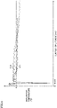
- Fig. 4 is a graph showing the relation between an elapsed time period since activation of the compressor in Fig. 3 and a saturation temperature of the refrigerant suctioned into compressor 1.
- Fig. 4 shows graphs C10 and C11 obtained when R32 and R290, respectively, are used as refrigerant. As the saturation temperature is lower, the pressure of the refrigerant suctioned into compressor 1 is lower. As shown in Fig. 4 , when comparing the saturation temperature of graph C10 and the saturation temperature of graph C11 in the time zone from activation of compressor 1 to an elapsed time period Tm10, a lowest temperature Ts11 of R290 is lower than a lowest temperature Ts10 of R32.
- the operation mode of refrigeration cycle apparatus 100 is set in the activation mode when compressor 1 is activated.
- the circulation flow path of the refrigerant is changed so as to suppress a decrease in amount of the refrigerant distributed in evaporator 4.
- the operation mode is switched in the order of the activation mode and the normal mode. Thereby, reduction in pressure of the refrigerant suctioned into compressor 1 at the start of the operation of refrigeration cycle apparatus 100 can be suppressed irrespective of the type of refrigerant.
- Fig. 5 is a functional block diagram showing the configuration of refrigeration cycle apparatus 100 according to the first embodiment together with the flow of refrigerant in the activation mode.
- controller 10 activates compressor 1 in the activation mode.
- controller 10 closes solenoid valve 6, opens solenoid valve 7, and fully opens expansion valve 3.
- Controller 10 forms a circulation flow path such that the refrigerant discharged from compressor 1 bypasses condenser 2.
- solenoid valve 6 is closed and solenoid valve 7 is opened, the refrigerant discharged from compressor 1 is guided to evaporator 4 without flowing through condenser 2.
- Controller 10 controls compressor 1 and flow rate adjuster 130 to reduce the amount of refrigerant flowing per unit time through condenser 2 in the activation mode to be less than the amount of refrigerant in the normal mode.
- controller 10 facilitates movement of the refrigerant stored in condenser 2 toward evaporator 4.
- the refrigerant is distributed more in evaporator 4 than in condenser 2, thereby preventing an abrupt decrease in amount of the refrigerant distributed in evaporator 4 at activation of compressor 1.
- the refrigerant suctioned into compressor 1 at activation of compressor 1 is prevented from becoming negative pressure.
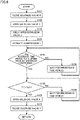
- Fig. 6 is a flowchart showing the flow of an operation mode switching process performed by controller 10 in Figs. 1 and 5 .
- the process shown in Fig. 6 is invoked at the start of the operation of refrigeration cycle apparatus 100 by the main routine that integrally controls refrigeration cycle apparatus 100.
- each step will be simply referred to as S.
- controller 10 starts the activation mode in S101.
- controller 10 closes solenoid valve 6, and then advances the process to S102.
- controller 10 opens solenoid valve 7, and then advances the process to S103.
- controller 10 fully opens expansion valve 3, and then advances the process to S104.
- controller 10 activates compressor 1, and then advances the process to S105.
- controller 10 determines whether a reference time period Tm1 has elapsed or not since activation of compressor 1.
- Reference time period Tm1 is determined as appropriate by experiments by real machines or simulations.
- controller 10 waits for a prescribed time period in S106, and then returns the process to S105.
- controller 10 determines in S107 whether or not temperature T1 is higher than a reference temperature Trf1.
- Reference temperature Trf1 is determined as appropriate by experiments by real machines or simulations.
- controller 10 waits for a prescribed time period in S108, and then returns the process to S107.
- controller 10 advances the process to S109 and switches the operation mode from the activation mode to the normal mode.
- the activation mode is ended and the normal mode is started.
- controller 10 opens solenoid valve 6, and then advances the process to S110.
- controller 10 closes solenoid valve 7, and then returns the process to the main routine.
- Fig. 6 after a lapse of the reference time period since activation of compressor 1, it is determined based on temperature T1 whether or not to end the activation mode. In this case, the determination about whether or not to end the activation mode may be made based on the elapsed time period since the activation of compressor 1. In the case where the determination about whether or not to end the activation mode is made based on the elapsed time period since the activation of compressor 1, a temperature sensor for measuring the temperature of the refrigerant flowing out of evaporator 4 is not required, so that the manufacturing cost of the refrigeration cycle apparatus can be reduced.
- Fig. 7 is a flowchart showing another example of the operation mode switching process performed by controller 10 in Figs. 1 and 5 .
- the process shown in Fig. 7 is the same as the process in Fig. 6 except that the process in Fig. 7 includes S115 in place of S105 in Fig. 6 and does not include S107 and S108 in Fig. 6 .
- controller 10 determines in S115 whether a reference time period Tm11 (> Tm1) has elapsed or not since the activation of compressor 1.
- Reference time period Tm11 is determined as appropriate by experiments by real machines or simulations.
- controller 10 waits for a prescribed time period in S106, and then returns the process to S115.
- controller 10 performs S109 and S110, and then returns the process to the main routine.
- the activation mode is ended and the normal mode is started.
- the refrigerant discharged from compressor 1 in the activation mode is guided to the flow path between expansion valve 3 and evaporator 4.
- the refrigerant discharged from compressor 1 in the activation mode may be guided to the flow path between condenser 2 and expansion valve 3 as in a refrigeration cycle apparatus 100A according to the modification of the first embodiment shown in Fig. 8 .
- the circulation flow path is formed such that the refrigerant discharged from the compressor bypasses the condenser.
- a circulation flow path is formed such that refrigerant discharged from a compressor in the activation mode bypasses a condenser, and also, the refrigerant flowing out of an evaporator is heated by the refrigerant discharged from the compressor to thereby lower the density of the refrigerant suctioned into the compressor.
- Fig. 9 is a functional block diagram showing a configuration of a refrigeration cycle apparatus 200 according to the second embodiment together with a flow of refrigerant in a normal mode.
- refrigeration cycle apparatus 200 includes an outdoor unit 210 and an indoor unit 220.
- Indoor unit 220 is disposed in an indoor space.
- Outdoor unit 210 is disposed outdoors.
- Refrigerant including R290 is sealed in refrigeration cycle apparatus 200.
- Indoor unit 220 includes a condenser 22 (the first heat exchanger).
- Outdoor unit 210 includes a compressor 21, an expansion valve 23, an evaporator 24 (the second heat exchanger), a gas-liquid separator 25, a check valve 28, an internal heat exchanger 29 (the third heat exchanger), a flow rate adjuster 230, a temperature sensor TS2, and a controller 20.
- Flow rate adjuster 230 has a solenoid valve 26 (the first valve) and a solenoid valve 27 (the second valve). Controller 20 may be included in indoor unit 220 or may be provided separately from outdoor unit 210 and indoor unit 220.
- the operation mode of refrigeration cycle apparatus 200 includes an activation mode and a normal mode.
- the activation mode is executed when compressor 21 is activated.
- the normal mode is executed subsequently to the activation mode.
- the refrigerant circulates in a circulation direction (the first circulation direction) in which the refrigerant flows sequentially through compressor 21, condenser 22, expansion valve 23, and evaporator 24.
- Gas-liquid separator 25 receives refrigerant from evaporator 24, separates the received refrigerant into gas refrigerant and liquid refrigerant, stores the liquid refrigerant therein, and guides the gas refrigerant to compressor 21. Gas-liquid separator 25 prevents the liquid refrigerant from being suctioned into compressor 21. Gas-liquid separator 25 includes an accumulator or a suction muffler.
- check valve 28 is connected between condenser 22 and internal heat exchanger 29.
- the forward direction of check valve 28 corresponds to the direction from condenser 22 toward internal heat exchanger 29.
- Solenoid valve 26 is connected between a discharge port of compressor 21 and condenser 22.
- Solenoid valve 27 is connected between the discharge port of compressor 21 and a flow path extending between check valve 28 and internal heat exchanger 29.
- Controller 20 switches the operation mode of refrigeration cycle apparatus 200. In the normal mode, controller 20 opens solenoid valve 26 and closes solenoid valve 27. From temperature sensor TS2, controller 20 acquires a temperature T2 of the refrigerant flowing between internal heat exchanger 29 and gas-liquid separator 25. Controller 20 controls compressor 21 and expansion valve 23 as in the first embodiment.
- Fig. 10 is a functional block diagram showing the configuration of refrigeration cycle apparatus 200 according to the second embodiment together with a flow of refrigerant in the activation mode.
- controller 20 activates compressor 21 in the activation mode.
- controller 20 closes solenoid valve 26, opens solenoid valve 27, and fully opens expansion valve 23.
- Controller 20 forms a circulation flow path such that the refrigerant discharged from compressor 21 bypasses condenser 22.
- solenoid valve 26 is closed and solenoid valve 27 is opened, the refrigerant discharged from compressor 21 is guided to the flow path between check valve 28 and internal heat exchanger 29 without flowing through condenser 22.
- Check valve 28 prevents the refrigerant from flowing from this flow path into condenser 22.
- the refrigerant having flowed through internal heat exchanger 29 passes through expansion valve 23 and reaches evaporator 24.
- the refrigerant flowing out of evaporator 24 is heated in internal heat exchanger 29 by the refrigerant discharged from compressor 21, and then suctioned into compressor 21.
- Controller 20 controls compressor 21 and flow rate adjuster 230 to reduce the amount of refrigerant flowing per unit time through condenser 22 in the activation mode to be less than the amount of refrigerant in the normal mode.
- controller 20 facilitates movement of the refrigerant stored in condenser 22 to evaporator 24.
- the refrigerant is distributed more in evaporator 24 than in condenser 22.
- an abrupt decrease in amount of the refrigerant distributed in evaporator 24 at activation of compressor 21 is prevented.
- the refrigerant flowing out of evaporator 24 is heated in internal heat exchanger 29 by the refrigerant discharged from compressor 21, so that the refrigerant suctioned into compressor 21 is reduced in density. Since the amount of refrigerant suctioned into compressor 21 per unit time decreases, the amount of refrigerant remaining in evaporator 24 increases. As a result, the refrigerant suctioned into compressor 21 at activation of compressor 21 is prevented from becoming negative pressure.
- Fig. 11 is a flowchart showing a flow of an operation mode switching process performed by controller 20 in Figs. 9 and 10 .
- the process shown in Fig. 11 is invoked at the start of the operation of refrigeration cycle apparatus 200 by the main routine that integrally controls refrigeration cycle apparatus 200.
- controller 20 starts the activation mode in S201.
- controller 20 closes solenoid valve 26, and then advances the process to S202.
- controller 20 opens solenoid valve 27, and then advances the process to S203.
- controller 20 fully opens expansion valve 23, and then advances the process to S204.
- controller 20 activates compressor 21, and then advances the process to S205.
- controller 20 determines whether a reference time period Tm2 has elapsed or not since the activation of compressor 21.
- Reference time period Tm2 is determined as appropriate by experiments by real machines or simulations.
- controller 20 waits for a prescribed time period in S206, and then returns the process to S205.
- controller 20 determines in S207 whether or not temperature T2 is higher than a reference temperature Trf2.
- Reference temperature Trf2 is determined as appropriate by experiments by real machines or simulations.
- controller 20 waits for a prescribed time period in S208, and then returns the process to S207.
- controller 20 advances the process to S209 and then switches the operation mode from the activation mode to the normal mode.
- the activation mode is ended and the normal mode is started.
- controller 20 opens solenoid valve 26, and then advances the process to S210.
- controller 20 closes solenoid valve 27, and then returns the process to the main routine.
- the circulation flow path is formed such that the refrigerant discharged from the compressor bypasses the condenser.
- a circulation flow path is formed such that refrigerant discharged from the compressor in the activation mode bypasses a part of the evaporator.
- Fig. 12 is a functional block diagram showing a configuration of a refrigeration cycle apparatus 300 according to the third embodiment together with a flow of refrigerant in a normal mode.
- refrigeration cycle apparatus 300 includes an outdoor unit 310 and an indoor unit 320.
- Indoor unit 320 is disposed in an indoor space.
- Outdoor unit 310 is disposed outdoors.
- Refrigerant including R290 is sealed in refrigeration cycle apparatus 300.
- Indoor unit 320 includes a condenser 32 (the first heat exchanger).
- Outdoor unit 310 includes a compressor 31, an expansion valve 33, an evaporator 34 (the second heat exchanger), a gas-liquid separator 35, a flow rate adjuster 330, a temperature sensor TS3, and a controller 30.
- Evaporator 34 includes a heat exchange unit 341 (the first heat exchange unit) and a heat exchange unit 342 (the second heat exchange unit).
- Flow rate adjuster 330 has a solenoid valve 36.
- Controller 30 may be included in indoor unit 320 or may be provided separately from outdoor unit 310 and indoor unit 320.
- the operation mode of refrigeration cycle apparatus 300 includes an activation mode and a normal mode.
- the activation mode is executed when compressor 31 is activated.
- the normal mode is executed subsequently to the activation mode.
- the refrigerant circulates in a circulation direction (the first circulation direction) in which the refrigerant flows sequentially through compressor 31, condenser 32, expansion valve 33, heat exchange unit 341, and heat exchange unit 342.
- Solenoid valve 36 is connected between: a flow path between condenser 32 and expansion valve 33; and a flow path between heat exchange unit 341 and heat exchange unit 342.
- Gas-liquid separator 35 receives refrigerant from evaporator 34, separates the received refrigerant into gas refrigerant and liquid refrigerant, stores the liquid refrigerant therein, and guides the gas refrigerant to compressor 31.
- Gas-liquid separator 35 prevents the liquid refrigerant from being suctioned into compressor 31.
- Gas-liquid separator 35 includes an accumulator or a suction muffler.
- Controller 30 switches the operation mode of refrigeration cycle apparatus 300. In the normal mode, controller 30 opens expansion valve 33 and closes solenoid valve 36. From temperature sensor TS3, controller 30 acquires a temperature T3 of the refrigerant flowing out of evaporator 34. Controller 30 controls compressor 31 and expansion valve 33 as in the first embodiment.
- Fig. 13 is a functional block diagram showing the configuration of refrigeration cycle apparatus 300 according to the third embodiment together with a flow of refrigerant in the activation mode.
- controller 30 activates compressor 31 in the activation mode.
- controller 30 closes expansion valve 33 and opens solenoid valve 36.
- Controller 30 forms a circulation flow path such that the refrigerant discharged from compressor 31 bypasses heat exchange unit 341.
- expansion valve 33 is closed and solenoid valve 36 is opened, the refrigerant discharged from compressor 31 is guided to heat exchange unit 341 without flowing through heat exchange unit 342.
- Controller 30 controls compressor 31 and flow rate adjuster 330 to reduce the amount of refrigerant flowing per unit time through expansion valve 33 in the activation mode to be less than the amount of refrigerant in the normal mode.
- the refrigerant stored in heat exchange unit 341 moves to heat exchange unit 342.
- the refrigerant is distributed more in heat exchange unit 342 than in heat exchange unit 341.
- an abrupt decrease in amount of the refrigerant flowing between evaporator 34 and compressor 31 at activation of compressor 31 is prevented.
- the refrigerant suctioned into compressor 31 at activation of compressor 31 is prevented from becoming negative pressure.
- Fig. 14 is a flowchart showing a flow of an operation mode switching process performed by controller 30 in Figs. 12 and 13 .
- the process shown in Fig. 14 is invoked at the start of the operation of refrigeration cycle apparatus 300 by the main routine that integrally controls refrigeration cycle apparatus 300.
- controller 30 starts the activation mode in S301.
- controller 30 closes expansion valve 33, and then advances the process to S302.
- controller 30 opens solenoid valve 36, and then advances the process to S304.
- controller 30 activates compressor 31, and then advances the process to S305.
- controller 30 determines whether a reference time period Tm3 has elapsed or not since the activation of compressor 31.
- Reference time period Tm3 is determined as appropriate by experiments by real machines or simulations.
- controller 30 waits for a prescribed time period in S306, and then returns the process to S305.
- controller 30 determines in S307 whether or not temperature T3 is higher than a reference temperature Trf3.
- Reference temperature Trf3 is determined as appropriate by experiments by real machines or simulations.
- controller 30 waits for a prescribed time period in S308, and then returns the process to S307.
- controller 30 advances the process to S309 and then switches the operation mode from the activation mode to the normal mode.
- the activation mode is ended and the normal mode is started.
- controller 30 opens expansion valve 33, and then advances the process to S310.
- controller 30 closes solenoid valve 36, and then returns the process to the main routine.
- the compressor has one suction port.
- a compressor includes two compression mechanisms and also has two suction ports corresponding to the two respective compression mechanisms.
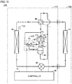
- Fig. 15 is a functional block diagram showing a configuration of a refrigeration cycle apparatus 400 according to the fourth embodiment together with a flow of refrigerant in a cooling operation.
- refrigeration cycle apparatus 400 includes an outdoor unit 410 and an indoor unit 420.
- Indoor unit 420 is disposed in an indoor space.
- Outdoor unit 410 is disposed outdoors.
- Refrigerant including R290 is sealed in refrigeration cycle apparatus 400.
- Indoor unit 420 includes a heat exchanger 42 (the first heat exchanger).
- Outdoor unit 410 includes a compressor 41, an expansion valve 43, a heat exchanger 44 (the second heat exchanger), a gas-liquid separator 45, a four-way valve 46, a flow rate adjuster 430, a temperature sensor TS4, and a controller 40.
- Flow rate adjuster 430 has a three-way valve 47.
- Controller 40 may be included in indoor unit 420 or may be provided separately from outdoor unit 410 and indoor unit 420.
- Compressor 41 includes a suction port Ps1 (the first suction port), a suction port Ps2 (the second suction port), a discharge port Pd, a compression mechanism 411 (the first compression mechanism), and a compression mechanism 412 (the second compression mechanism).
- Compression mechanism 411 which is connected between suction port Ps1 and discharge port Pd, compresses the refrigerant received through suction port Ps1 and then discharges the refrigerant through discharge port Pd.
- Compression mechanism 412 which is connected between suction port Ps2 and discharge port Pd, compresses the refrigerant received through suction port Ps2 and then discharges the refrigerant through discharge port Pd.
- Compressor 41 is a twin rotary compressor.
- Three-way valve 47 includes a port P1 (the first port), a port P2 (the second port), and a port P3 (the third port).
- Port P1 is connected to suction port Ps2.
- Port P2 is in communication with suction port Ps1 through gas-liquid separator 45.
- Port P3 is connected to discharge port Pd.
- Three-way valve 47 selectively switches the state of communication among ports P1 to P3 between the state where port P1 is in communication with port P2 and the state where port P1 is in communication with port P3.
- Fig. 15 and Figs. 16 and 17 described later each port not in communication with other ports are shown in dotted pattern.
- Controller 40 controls the driving frequency of each of compression mechanisms 411 and 412, for example, to fall within a range of 50 Hz to 60 Hz to thereby control the amount of refrigerant discharged per unit time by compressor 41 such that the temperature in the indoor space reaches a target temperature (for example, a temperature set by a user). Controller 40 controls expansion valve 43 as in the first embodiment.
- Controller 40 controls four-way valve 46 to switch the direction in which the refrigerant circulates.
- controller 40 allows discharge port Pd of compressor 41 to communicate with heat exchanger 44, and allows suction ports Ps1 and Ps2 of compressor 41 to communicate with heat exchanger 42.
- controller 40 allows ports P1 and P2 to communicate with each other.
- the refrigerant circulates in the circulation direction (the second circulation direction) in which the refrigerant flows sequentially through compressor 41, heat exchanger 44, expansion valve 43, and heat exchanger 42.
- heat exchangers 42 and 44 function as an evaporator and a condenser, respectively.
- Gas-liquid separator 45 receives the refrigerant from heat exchanger 42, separates the received refrigerant into gas refrigerant and liquid refrigerant, stores the liquid refrigerant therein, and guides the gas refrigerant to compressor 41. Gas-liquid separator 45 prevents the liquid refrigerant from being suctioned into compressor 41. Gas-liquid separator 45 includes an accumulator or a suction muffler.
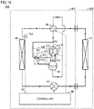
- Fig. 16 is a functional block diagram showing the configuration of refrigeration cycle apparatus 400 according to the fourth embodiment together with a flow of refrigerant in a normal mode of a heating operation.
- the operation modes of refrigeration cycle apparatus 400 in the heating operation include an activation mode and a normal mode.
- the activation mode is executed when compressor 41 is activated.
- the normal mode is executed subsequently to the activation mode.
- controller 40 allows discharge port Pd of compressor 41 to communicate with heat exchanger 42, and allows suction ports Ps1 and Ps2 of compressor 41 to communicate with heat exchanger 44.
- controller 40 allows ports P1 and P2 to communicate with each other.
- controller 40 operates compression mechanisms 411 and 412. From temperature sensor TS4, controller 40 acquires a temperature T4 of the refrigerant flowing out of heat exchanger 44 in the heating operation.
- the refrigerant circulates in the circulation direction (the first circulation direction) in which the refrigerant flows sequentially through compressor 41, heat exchanger 42, expansion valve 43, and heat exchanger 44.
- heat exchangers 42 and 44 function as a condenser and an evaporator, respectively.
- Fig. 17 is a functional block diagram showing the configuration of refrigeration cycle apparatus 400 according to the fourth embodiment together with a flow of refrigerant in the activation mode of the heating operation.
- controller 40 allows ports P1 and P3 to communicate with each other, and activates compression mechanism 411 but does not activate compression mechanism 412.
- compression mechanism 412 that is not operated is shown in dotted pattern. Since compression mechanism 412 is not operated in the activation mode, the amount of refrigerant suctioned per unit time into compressor 41 is smaller than the amount of refrigerant suctioned into compressor 41 in the normal mode.
- Controller 40 controls compressor 41 and flow rate adjuster 430 to reduce the amount of refrigerant flowing per unit time through heat exchanger 42 and expansion valve 43 in the activation mode to be less than the amount of refrigerant in the normal mode.
- the amount of refrigerant suctioned per unit time into compressor 41 is smaller than that in the normal mode. Thereby, an abrupt decrease in amount of the refrigerant flowing between heat exchanger 44 and compressor 41 at activation of compressor 41 is prevented. As a result, the refrigerant suctioned into compressor 41 at activation of compressor 41 is prevented from becoming negative pressure.
- Fig. 18 is a flowchart showing a flow of an operation mode switching process performed by controller 40 in Figs. 15 to 17 .
- the process shown in Fig. 14 is invoked at the start of the operation of refrigeration cycle apparatus 400 by the main routine that integrally controls refrigeration cycle apparatus 400.
- controller 40 starts the activation mode in S401.
- controller 40 allows ports P1 and P3 to communicate with each other and then advances the process to S403.
- controller 40 fully opens expansion valve 43 and then advances the process to S404.
- controller 40 activates compression mechanism 411, and then advances the process to S405.
- controller 40 determines whether a reference time period Tm4 has elapsed or not since activation of compression mechanism 411.
- Reference time period Tm4 is determined as appropriate by experiments by real machines or simulations.
- controller 40 waits for a prescribed time period in S406, and then returns the process to S405.
- controller 40 determines in S407 whether or not temperature T4 is higher than reference temperature Trf4.
- Reference temperature Trf4 is determined as appropriate by experiments by real machines or simulations.
- controller 40 waits for a prescribed time period in S408, and then returns the process to S407.
- controller 40 advances the process to S409 and then switches the operation mode from the activation mode to the normal mode.
- the activation mode is ended and the normal mode is started.
- controller 40 allows ports P1 and P2 to communicate with each other, and then advances the process to S410.
- controller 40 activates compression mechanism 412, and then returns the process to the main routine.
- the refrigerant flowing out of the evaporator is heated by the refrigerant discharged from the compressor, thereby lowering the density of the refrigerant suctioned into the compressor.
- the refrigerant suctioned into a compressor is heated by a heater.
- Fig. 19 is a functional block diagram showing a configuration of a refrigeration cycle apparatus 500 according to the fifth embodiment together with a flow of refrigerant in a cooling operation.
- refrigeration cycle apparatus 500 includes an outdoor unit 510 and an indoor unit 520.
- Indoor unit 520 is disposed in an indoor space.
- Outdoor unit 510 is disposed outdoors.
- Refrigerant including R290 is sealed in refrigeration cycle apparatus 500.
- Indoor unit 520 includes a heat exchanger 52 (the first heat exchanger).
- Outdoor unit 510 includes a compressor 51, an expansion valve 53, a heat exchanger 54 (the second heat exchanger), a gas-liquid separator 55, a four-way valve 56, a flow rate adjuster 530, a temperature sensor TS5, and a controller 50.
- Flow rate adjuster 530 includes a heater 57.
- Controller 50 may be included in indoor unit 520 or may be provided separately from outdoor unit 510 and indoor unit 520.
- Controller 50 controls compressor 51 and expansion valve 53 as in the first embodiment. Controller 50 controls four-way valve 56 to switch the direction in which the refrigerant circulates.
- controller 50 allows a discharge port of compressor 51 to communicate with heat exchanger 54, and also allows a suction port of compressor 51 to communicate with heat exchanger 52.
- the refrigerant circulates in the circulation direction (the second circulation direction) in which the refrigerant flows sequentially through compressor 51, heat exchanger 54, expansion valve 53, and heat exchanger 52.
- heat exchangers 52 and 54 function as an evaporator and a condenser, respectively.
- Gas-liquid separator 55 receives the refrigerant from heat exchanger 52, separates the received refrigerant into gas refrigerant and liquid refrigerant, stores the liquid refrigerant therein, and guides the gas refrigerant to compressor 51. Gas-liquid separator 55 prevents the liquid refrigerant from being suctioned into compressor 51. Gas-liquid separator 55 includes an accumulator or a suction muffler.
- Heater 57 is disposed to heat the refrigerant flowing into gas-liquid separator 55. In the cooling operation, heater 57 is not operating.
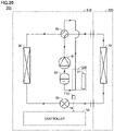
- Fig. 20 is a functional block diagram showing the configuration of refrigeration cycle apparatus 500 according to the fifth embodiment together with a flow of refrigerant in the normal mode of the heating operation.
- Operation modes of refrigeration cycle apparatus 500 in the heating operation include an activation mode and a normal mode.
- the activation mode is executed when compressor 51 is activated.
- the normal mode is executed subsequently to the activation mode.
- controller 50 allows a discharge port of compressor 51 to communicate with heat exchanger 52, and allows a suction port of compressor 51 to communicate with heat exchanger 54. Controller 50 does not activate heater 57 in the normal mode of the heating operation. From temperature sensor TS5, controller 50 acquires a temperature T5 of the refrigerant having flowed through a heating portion of heater 57 in the heating operation. This heating portion is included in a flow path through which the refrigerant flowing between heat exchanger 54 and compressor 51 in the heating operation passes.
- the refrigerant circulates in the circulation direction (the first circulation direction) in which the refrigerant flows sequentially through compressor 51, heat exchanger 52, expansion valve 53, and heat exchanger 54.
- heat exchangers 52 and 54 function as a condenser and an evaporator, respectively.
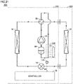
- Fig. 21 is a functional block diagram showing the configuration of refrigeration cycle apparatus 500 according to the fifth embodiment together with a flow of refrigerant in an activation mode of the heating operation.
- controller 50 activates heater 57 in the activation mode. Due to heating by heater 57, the density of the refrigerant suctioned into compressor 51 in the activation mode is lower than the density of the refrigerant suctioned into compressor 51 in the normal mode.
- Controller 50 controls compressor 51 and flow rate adjuster 530 to reduce the amount of refrigerant flowing per unit time through heat exchanger 52 and expansion valve 53 in the activation mode to be less than the amount of refrigerant in the normal mode.
- the amount of refrigerant suctioned per unit time into compressor 51 decreases, thereby preventing an abrupt decrease in amount of the refrigerant flowing between heat exchanger 54 and compressor 51 at activation of compressor 51.
- the refrigerant suctioned into compressor 51 at activation of compressor 51 is prevented from becoming negative pressure.
- Fig. 22 is a flowchart showing a flow of an operation mode switching process performed by controller 50 in Figs. 19 to 21 .
- the process shown in Fig. 22 is invoked at the start of the operation of refrigeration cycle apparatus 500 by the main routine that integrally controls refrigeration cycle apparatus 500.
- controller 50 starts the activation mode in S501.
- controller 50 activates heater 57, and then advances the process to S503.
- controller 50 fully opens expansion valve 53, and then advances the process to S504.
- controller 50 activates compressor 51, and then advances the process to S505.
- controller 50 determines whether a reference time period Tm5 has elapsed or not since activation of compressor 51. Reference time period Tm5 is determined as appropriate by experiments by real machines or simulations. When reference time period Tm5 has not elapsed since activation of compressor 51 (NO in S505), controller 50 waits for a prescribed time period in S506 and then returns the process to S505. When reference time period Tm5 has elapsed since activation of compressor 51 (YES in S505), then in S507, controller 50 determines whether or not temperature T5 is higher than a reference temperature Trf5. Reference temperature Trf5 is determined as appropriate by experiments by real machines or simulations.
- controller 50 waits for a prescribed time period in S508, and then returns the process to S507.
- controller 50 advances the process to S509 and then switches the operation mode from the activation mode to the normal mode.
- the activation mode is ended and the normal mode is started.
- controller 50 deactivates heater 57 and then returns the process to the main routine.
Landscapes
- Engineering & Computer Science (AREA)
- Physics & Mathematics (AREA)
- Mechanical Engineering (AREA)
- Thermal Sciences (AREA)
- General Engineering & Computer Science (AREA)
- Air Conditioning Control Device (AREA)
- Compression-Type Refrigeration Machines With Reversible Cycles (AREA)
Abstract
Description
- The present invention relates to a refrigeration cycle apparatus.
- A refrigeration cycle apparatus has conventionally been known that has a function of suppressing reduction in pressure of refrigerant suctioned into a compressor at the start of the operation of the refrigeration cycle apparatus. For example,
Japanese Patent Laying-Open No. 2015-94558 - PTL 1:
Japanese Patent Laying-Open No. 2015-94558 - Depending on refrigerant, pressure reduction may abruptly occur when the compressor is activated. Thus, depending on refrigerant, there is a possibility that the pressure of the refrigerant suctioned into the compressor may decrease below the atmospheric pressure (may become negative pressure) while determining whether or not the pressure of the refrigerant suctioned into the compressor is equal to or lower than the set pressure. In the heat pump system disclosed in
PTL 1, however, refrigerant other than such HFO refrigerant is not taken into consideration. - The present invention has been made in order to solve the above-described problems, and an object of the present invention is to suppress reduction in pressure of refrigerant suctioned into a compressor at the start of the operation of a refrigeration cycle apparatus, irrespective of type of refrigerant.
- In a refrigeration cycle apparatus according to the present invention, refrigerant circulates. The refrigeration cycle apparatus includes a compressor, a first heat exchanger, a second heat exchanger, an expansion valve, a flow rate adjuster, and a controller. The flow rate adjuster is configured to adjust an amount of refrigerant flowing per unit time through at least one of the first heat exchanger and the expansion valve. The controller is configured to switch an operation mode of the refrigeration cycle apparatus. The operation mode includes an activation mode and a normal mode. The activation mode is executed when the compressor is activated. The normal mode is executed after the activation mode. In the normal mode, the refrigerant circulates in a first circulation direction in which the refrigerant flows sequentially through the compressor, the first heat exchanger, the expansion valve, and the second heat exchanger. The controller is configured to control the compressor and the flow rate adjuster to reduce the amount of refrigerant that flows per unit time through at least one of the first heat exchanger and the expansion valve in the activation mode to be less than the amount of refrigerant in the normal mode.
- According to the present invention, the amount of refrigerant flowing per unit time through at least one of the first heat exchanger and the expansion valve in the activation mode is reduced to be less than the amount of refrigerant in the normal mode, and thereby, reduction in pressure of the refrigerant suctioned into the compressor at the start of the operation of the refrigeration cycle apparatus is suppressed irrespective of the type of refrigerant.
-
-
Fig. 1 is a functional block diagram showing a configuration of a refrigeration cycle apparatus according to a first embodiment together with a flow of refrigerant in a normal mode. -
Fig. 2 is a functional block diagram showing a configuration of a controller inFig. 1 . -
Fig. 3 is a functional block diagram showing a configuration of a refrigeration cycle apparatus according to a comparative example. -
Fig. 4 is a graph showing the relation between an elapsed time period since activation of a compressor inFig. 3 and a saturation temperature of refrigerant suctioned into the compressor. -
Fig. 5 is a functional block diagram showing a configuration of the refrigeration cycle apparatus according to the first embodiment together with the flow of refrigerant in an activation mode. -
Fig. 6 is a flowchart showing a flow of an operation mode switching process performed by a controller inFigs. 1 and5 . -
Fig. 7 is a flowchart showing another example of the operation mode switching process performed by the controller inFigs. 1 and5 . -
Fig. 8 is a functional block diagram showing a configuration of a refrigeration cycle apparatus according to a modification of the first embodiment together with a flow of refrigerant in the activation mode. -
Fig. 9 is a functional block diagram showing a configuration of a refrigeration cycle apparatus according to a second embodiment together with a flow of refrigerant in a normal mode. -
Fig. 10 is a functional block diagram showing the configuration of the refrigeration cycle apparatus according to the second embodiment together with a flow of refrigerant in an activation mode. -
Fig. 11 is a flowchart showing a flow of an operation mode switching process performed by a controller inFigs. 9 and10 . -
Fig. 12 is a functional block diagram showing a configuration of a refrigeration cycle apparatus according to a third embodiment together with a flow of refrigerant in a normal mode. -
Fig. 13 is a functional block diagram showing the configuration of the refrigeration cycle apparatus according to the third embodiment together with a flow of refrigerant in an activation mode. -
Fig. 14 is a flowchart showing a flow of an operation mode switching process performed by a controller inFigs. 12 and13 . -
Fig. 15 is a functional block diagram showing a configuration of a refrigeration cycle apparatus according to a fourth embodiment together with a flow of refrigerant in a cooling operation. -
Fig. 16 is a functional block diagram showing the configuration of the refrigeration cycle apparatus according to the fourth embodiment together with a flow of refrigerant in a normal mode of a heating operation. -
Fig. 17 is a functional block diagram showing the configuration of the refrigeration cycle apparatus according to the fourth embodiment together with a flow of refrigerant in an activation mode of the heating operation. -
Fig. 18 is a flowchart showing a flow of an operation mode switching process performed by a controller inFigs. 15 to 17 . -
Fig. 19 is a functional block diagram showing a configuration of a refrigeration cycle apparatus according to a fifth embodiment together with a flow of refrigerant in a cooling operation. -
Fig. 20 is a functional block diagram showing the configuration of the refrigeration cycle apparatus according to the fifth embodiment together with a flow of refrigerant in a normal mode of a heating operation. -
Fig. 21 is a functional block diagram showing the configuration of the refrigeration cycle apparatus according to the fifth embodiment together with a flow of refrigerant in an activation mode of the heating operation. -
Fig. 22 is a flowchart showing a flow of an operation mode switching process performed by a controller inFigs. 19 to 21 . - The following describes embodiments of the present invention with reference to the accompanying drawings, in which the same or corresponding portions are denoted by the same reference characters, and description thereof will not basically be repeated.
-
Fig. 1 is a functional block diagram showing a configuration of arefrigeration cycle apparatus 100 according to the first embodiment together with a flow of refrigerant in a normal mode. The closed valve inFig. 1 is shown in dotted pattern. The same also applies toFigs. 5 ,8 to 10 ,12 , and13 , which will be described later. - As shown in
Fig. 1 , arefrigeration cycle apparatus 100 includes anoutdoor unit 110 and anindoor unit 120.Indoor unit 120 is disposed in an indoor space.Outdoor unit 110 is disposed outside the indoor space (outdoors). Refrigerant including R290 is sealed inrefrigeration cycle apparatus 100. -
Indoor unit 120 includes a condenser 2 (the first heat exchanger).Outdoor unit 110 includes acompressor 1, anexpansion valve 3, an evaporator 4 (the second heat exchanger), a gas-liquid separator 5, aflow rate adjuster 130, a temperature sensor TS1, and acontroller 10.Flow rate adjuster 130 has a solenoid valve 6 (the first valve) and a solenoid valve 7 (the second valve).Controller 10 may be included inindoor unit 120 or may be provided separately fromoutdoor unit 110 andindoor unit 120. - The operation mode of
refrigeration cycle apparatus 100 includes an activation mode and a normal mode. The activation mode is executed whencompressor 1 is activated. The normal mode is executed subsequently to the activation mode. The normal mode may be executed after the activation mode, and another operation mode may be executed between the activation mode and the normal mode. In the normal mode ofrefrigeration cycle apparatus 100, the refrigerant circulates in a circulation direction (the first circulation direction) in which the refrigerant flows sequentially throughcompressor 1,condenser 2,expansion valve 3, andevaporator 4. -
Solenoid valve 6 is connected between a discharge port ofcompressor 1 andcondenser 2.Solenoid valve 7 is connected between the discharge port ofcompressor 1 and a flow path extending betweenexpansion valve 3 andevaporator 4. Gas-liquid separator 5 receives refrigerant fromevaporator 4, separates the received refrigerant into refrigerant in a gas state (gas refrigerant) and refrigerant in a liquid state (liquid refrigerant), stores the liquid refrigerant therein, and guides the gas refrigerant tocompressor 1. Gas-liquid separator 5 prevents the liquid refrigerant from being suctioned intocompressor 1. Gas-liquid separator 5 includes an accumulator or a suction muffler. -
Controller 10 switches the operation mode ofrefrigeration cycle apparatus 100. In the normal mode,controller 10 openssolenoid valve 6 and closessolenoid valve 7. From temperature sensor TS1,controller 10 acquires a temperature T1 of the refrigerant flowing out ofevaporator 4.Controller 10 controls a driving frequency Fc ofcompressor 1, for example, to fall within a range of 50 Hz to 60 Hz, thereby controlling the amount of refrigerant discharged per unit time bycompressor 1 such that the temperature in the indoor space reaches a target temperature (for example, a temperature set by a user).Controller 10 controls the degree of opening ofexpansion valve 3 such that the pressure difference between the refrigerant discharged fromcompressor 1 but not yet depressurized and the refrigerant depressurized but not yet suctioned intocompressor 1 falls within a desired range of values.Expansion valve 3 may be controlled such that the degree of superheating and the degree of supercooling of the refrigerant reach their respective target values. -
Fig. 2 is a functional block diagram showing a configuration ofcontroller 10 inFig. 1 . As shown inFig. 2 ,controller 10 includescircuitry 11, amemory 12, and an input/output unit 13. Processingcircuit 11 may be dedicated hardware or may be a central processing unit (CPU) that executes a program stored inmemory 12. Whencircuitry 11 is dedicated hardware,circuitry 11 is, for example, a single circuit, a composite circuit, a programmed processor, a parallel programmed processor, an application specific integrated circuit (ASIC), a field programmable gate array (FPGA), or a combination thereof. Whencircuitry 11 is a CPU, the function ofcontroller 10 is implemented by software, firmware, or a combination of software and firmware. Software or firmware is described as a program and stored inmemory 12. Processingcircuit 11 reads and executes the program stored in the memory.Memory 12 includes a nonvolatile or volatile semiconductor memory (for example, a random access memory (RAM), a read only memory (ROM), a flash memory, an erasable programmable read only memory (EPROM) or an electrically erasable programmable read only memory (EEPROM)), a magnetic disk, a flexible disk, an optical disk, a compact disk, a mini disk, or a digital versatile disc (DVD). Note that the CPU is also referred to as a central processing unit, a processing unit, a computing unit, a microprocessor, a microcomputer, a processor, or a digital signal processor (DSP). - From the viewpoint of preventing global warming, reduction of a global warming potential (GWP) total amount value Tgwp of refrigerant used in a refrigeration cycle apparatus has recently been demanded. GWP total amount value Tgwp is represented by the following equation (1) using: a GWP value Rgwp as a physical property value specific to refrigerant; and a refrigerant amount Mchg sealed in
refrigeration cycle apparatus 100. - [Equation 1]

- Based on the equation (1), GWP total amount value Tgwp can be reduced by reducing refrigerant amount Mchg sealed in the refrigeration cycle apparatus. In order to reduce refrigerant amount Mchg, refrigerant having a relatively low density needs to be used. Such refrigerant may be low-pressure refrigerant for which working pressure is relatively low. The low-pressure refrigerant includes R290 (propane) or R454a, for example.
- When refrigerant having a relatively low density is used, refrigerant amount Mchg decreases. Thus, maintaining the performance of
refrigeration cycle apparatus 100 is an issue to be solved. The heating performance of the refrigeration cycle apparatus is represented by the following equation (2) using: a refrigerant circulation amount Gr discharged per unit time bycompressor 1; and an enthalpy difference Δh representing the change in latent heat of the refrigerant in a condensation process. - [Equation 2]

- Refrigerant circulation amount Gr is represented by the following equation (3) using: a stroke volume Vst as the amount of refrigerant discharged per revolution by a compression mechanism of
compressor 1; a density ρs of refrigerant suctioned intocompressor 1; and driving frequency Fc ofcompressor 1. - [Equation 3]

- Enthalpy difference Δh in the equation (2) differs for each refrigerant. Thus, refrigerant circulation amount Gr needs to be changed in order to change the refrigerant to low-pressure refrigerant for maintaining the heating performance of the refrigeration cycle apparatus. In the equation (3), density ρs of refrigerant is a physical property value specific to the refrigerant. When driving frequency Fc of
compressor 1 is controlled to fall within a prescribed range irrespective of the type of refrigerant, stroke volume Vst needs to be changed in order to change refrigerant circulation amount Gr. -
Fig. 3 is a functional block diagram showing a configuration of arefrigeration cycle apparatus 900 according to a comparative example.Refrigeration cycle apparatus 900 has the same configuration as that ofrefrigeration cycle apparatus 100 inFig. 1 except thatrefrigeration cycle apparatus 900 does not includesolenoid valves controller 90 in place ofcontroller 10. The following describes problems occurring when the refrigerant circulating throughrefrigeration cycle apparatus 900 is changed from R32 to R290 while maintaining the heating performance ofrefrigeration cycle apparatus 900. - The following Table 1 shows simulation results about the ratio of the value obtained when R290 is used to the value obtained when R32 is used, which is required for maintaining the heating performance when the refrigerant circulating through
refrigeration cycle apparatus 900 inFig. 3 is changed from R32 to R290. In this case, the above-mentioned values include values of the refrigerant amount, the refrigerant circulation amount, and the stroke volume. Note that R32 is an example of refrigerant that has conventionally been used in refrigeration cycle apparatuses.[Table 1] Values Ratio of Value Obtained When R290 is Used to Value Obtained When R32 is Used (%) Refrigerant Amount 52 Refrigerant Circulation Amount 88 Stroke Volume 210 - As shown in Table 1, the ratio of the refrigerant amount of R290 to the refrigerant amount of R32 is 52 % since R290 is lower in density than R32. The refrigerant circulation amount required for R290 is 88 % of the refrigerant circulation amount of R32. The stroke volume required when R290 is used is 210 % of the stroke volume required when R32 is used.
- When the stroke volume of
compressor 1 is increased in order to maintain the performance ofrefrigeration cycle apparatus 900, the amount of refrigerant distributed inevaporator 4 at activation ofcompressor 1 may abruptly decrease. It takes a certain amount of time for the refrigerant discharged fromcompressor 1 to flow throughcondenser 2 andexpansion valve 3 and reachevaporator 4. Thus, whencompressor 1 is activated, there may be a time zone in which the pressure of the refrigerant flowing betweenevaporator 4 andcompressor 1 abruptly decreases. -
Fig. 4 is a graph showing the relation between an elapsed time period since activation of the compressor inFig. 3 and a saturation temperature of the refrigerant suctioned intocompressor 1.Fig. 4 shows graphs C10 and C11 obtained when R32 and R290, respectively, are used as refrigerant. As the saturation temperature is lower, the pressure of the refrigerant suctioned intocompressor 1 is lower. As shown inFig. 4 , when comparing the saturation temperature of graph C10 and the saturation temperature of graph C11 in the time zone from activation ofcompressor 1 to an elapsed time period Tm10, a lowest temperature Ts11 of R290 is lower than a lowest temperature Ts10 of R32. In this time zone, the pressure of R290 suctioned intocompressor 1 abruptly decreases. When the refrigerant including R290 is used inrefrigeration cycle apparatus 900, the pressure of the refrigerant suctioned intocompressor 1 at activation ofcompressor 1 becomes negative pressure, which may lead to a failure inrefrigeration cycle apparatus 900. - Therefore, in
refrigeration cycle apparatus 100, the operation mode ofrefrigeration cycle apparatus 100 is set in the activation mode whencompressor 1 is activated. In the activation mode, the circulation flow path of the refrigerant is changed so as to suppress a decrease in amount of the refrigerant distributed inevaporator 4. When the operation ofrefrigeration cycle apparatus 100 is started, the operation mode is switched in the order of the activation mode and the normal mode. Thereby, reduction in pressure of the refrigerant suctioned intocompressor 1 at the start of the operation ofrefrigeration cycle apparatus 100 can be suppressed irrespective of the type of refrigerant. -
Fig. 5 is a functional block diagram showing the configuration ofrefrigeration cycle apparatus 100 according to the first embodiment together with the flow of refrigerant in the activation mode. As shown inFig. 5 ,controller 10 activatescompressor 1 in the activation mode. In the activation mode,controller 10 closes solenoidvalve 6, openssolenoid valve 7, and fully opensexpansion valve 3.Controller 10 forms a circulation flow path such that the refrigerant discharged fromcompressor 1 bypassescondenser 2. Whensolenoid valve 6 is closed andsolenoid valve 7 is opened, the refrigerant discharged fromcompressor 1 is guided toevaporator 4 without flowing throughcondenser 2. -
Controller 10controls compressor 1 and flowrate adjuster 130 to reduce the amount of refrigerant flowing per unit time throughcondenser 2 in the activation mode to be less than the amount of refrigerant in the normal mode. By fully openingexpansion valve 3,controller 10 facilitates movement of the refrigerant stored incondenser 2 towardevaporator 4. In the activation mode, the refrigerant is distributed more inevaporator 4 than incondenser 2, thereby preventing an abrupt decrease in amount of the refrigerant distributed inevaporator 4 at activation ofcompressor 1. As a result, the refrigerant suctioned intocompressor 1 at activation ofcompressor 1 is prevented from becoming negative pressure. -
Fig. 6 is a flowchart showing the flow of an operation mode switching process performed bycontroller 10 inFigs. 1 and5 . The process shown inFig. 6 is invoked at the start of the operation ofrefrigeration cycle apparatus 100 by the main routine that integrally controlsrefrigeration cycle apparatus 100. In the following description, each step will be simply referred to as S. - As shown in
Fig. 6 ,controller 10 starts the activation mode in S101. In S101,controller 10 closes solenoidvalve 6, and then advances the process to S102. In S102,controller 10 openssolenoid valve 7, and then advances the process to S103. In S103,controller 10 fully opensexpansion valve 3, and then advances the process to S104. In S104,controller 10 activatescompressor 1, and then advances the process to S105. - In S105,
controller 10 determines whether a reference time period Tm1 has elapsed or not since activation ofcompressor 1. Reference time period Tm1 is determined as appropriate by experiments by real machines or simulations. When reference time period Tm1 has not elapsed since the activation of compressor 1 (NO in S105),controller 10 waits for a prescribed time period in S106, and then returns the process to S105. When reference time period Tm1 has elapsed since the activation of compressor 1 (YES in S105),controller 10 determines in S107 whether or not temperature T1 is higher than a reference temperature Trf1. Reference temperature Trf1 is determined as appropriate by experiments by real machines or simulations. - When temperature T1 is equal to or lower than reference temperature Trf1 (NO in S107),
controller 10 waits for a prescribed time period in S108, and then returns the process to S107. When temperature T1 is higher than reference temperature Trf1 (YES in S107),controller 10 advances the process to S109 and switches the operation mode from the activation mode to the normal mode. When the condition shown in S107 is satisfied, the activation mode is ended and the normal mode is started. In S109,controller 10 openssolenoid valve 6, and then advances the process to S110. In S110,controller 10 closes solenoidvalve 7, and then returns the process to the main routine. - In
Fig. 6 , after a lapse of the reference time period since activation ofcompressor 1, it is determined based on temperature T1 whether or not to end the activation mode. In this case, the determination about whether or not to end the activation mode may be made based on the elapsed time period since the activation ofcompressor 1. In the case where the determination about whether or not to end the activation mode is made based on the elapsed time period since the activation ofcompressor 1, a temperature sensor for measuring the temperature of the refrigerant flowing out ofevaporator 4 is not required, so that the manufacturing cost of the refrigeration cycle apparatus can be reduced. -
Fig. 7 is a flowchart showing another example of the operation mode switching process performed bycontroller 10 inFigs. 1 and5 . The process shown inFig. 7 is the same as the process inFig. 6 except that the process inFig. 7 includes S115 in place of S105 inFig. 6 and does not include S107 and S108 inFig. 6 . - As shown in
Fig. 7 , after performing S101 to S104,controller 10 determines in S115 whether a reference time period Tm11 (> Tm1) has elapsed or not since the activation ofcompressor 1. Reference time period Tm11 is determined as appropriate by experiments by real machines or simulations. When reference time period Tm11 has not elapsed since the activation of compressor 1 (NO in S115),controller 10 waits for a prescribed time period in S106, and then returns the process to S115. When reference time period Tm11 has elapsed since the activation of compressor 1 (YES in S115),controller 10 performs S109 and S110, and then returns the process to the main routine. When the condition shown in S115 is satisfied, the activation mode is ended and the normal mode is started. - In the above description about the configuration in the first embodiment, the refrigerant discharged from
compressor 1 in the activation mode is guided to the flow path betweenexpansion valve 3 andevaporator 4. The refrigerant discharged fromcompressor 1 in the activation mode may be guided to the flow path betweencondenser 2 andexpansion valve 3 as in a refrigeration cycle apparatus 100A according to the modification of the first embodiment shown inFig. 8 . - As described above, according to the refrigeration cycle apparatus in the first embodiment and the modification thereof, reduction in pressure of the refrigerant suctioned into the compressor at the start of the operation of the refrigeration cycle apparatus can be suppressed irrespective of the type of refrigerant.
- In the above description about the configuration in the first embodiment, the circulation flow path is formed such that the refrigerant discharged from the compressor bypasses the condenser. In the following description about the configuration in the second embodiment, a circulation flow path is formed such that refrigerant discharged from a compressor in the activation mode bypasses a condenser, and also, the refrigerant flowing out of an evaporator is heated by the refrigerant discharged from the compressor to thereby lower the density of the refrigerant suctioned into the compressor.
-
Fig. 9 is a functional block diagram showing a configuration of arefrigeration cycle apparatus 200 according to the second embodiment together with a flow of refrigerant in a normal mode. As shown inFig. 9 ,refrigeration cycle apparatus 200 includes anoutdoor unit 210 and anindoor unit 220.Indoor unit 220 is disposed in an indoor space.Outdoor unit 210 is disposed outdoors. Refrigerant including R290 is sealed inrefrigeration cycle apparatus 200. -
Indoor unit 220 includes a condenser 22 (the first heat exchanger).Outdoor unit 210 includes acompressor 21, anexpansion valve 23, an evaporator 24 (the second heat exchanger), a gas-liquid separator 25, acheck valve 28, an internal heat exchanger 29 (the third heat exchanger), aflow rate adjuster 230, a temperature sensor TS2, and acontroller 20.Flow rate adjuster 230 has a solenoid valve 26 (the first valve) and a solenoid valve 27 (the second valve).Controller 20 may be included inindoor unit 220 or may be provided separately fromoutdoor unit 210 andindoor unit 220. - The operation mode of
refrigeration cycle apparatus 200 includes an activation mode and a normal mode. The activation mode is executed whencompressor 21 is activated. The normal mode is executed subsequently to the activation mode. In the normal mode ofrefrigeration cycle apparatus 200, the refrigerant circulates in a circulation direction (the first circulation direction) in which the refrigerant flows sequentially throughcompressor 21,condenser 22,expansion valve 23, andevaporator 24. - Gas-
liquid separator 25 receives refrigerant fromevaporator 24, separates the received refrigerant into gas refrigerant and liquid refrigerant, stores the liquid refrigerant therein, and guides the gas refrigerant tocompressor 21. Gas-liquid separator 25 prevents the liquid refrigerant from being suctioned intocompressor 21. Gas-liquid separator 25 includes an accumulator or a suction muffler. - In
internal heat exchanger 29, a heat exchange is performed between the refrigerant fromcondenser 22 and the refrigerant fromevaporator 24. Checkvalve 28 is connected betweencondenser 22 andinternal heat exchanger 29. The forward direction ofcheck valve 28 corresponds to the direction fromcondenser 22 towardinternal heat exchanger 29. -
Solenoid valve 26 is connected between a discharge port ofcompressor 21 andcondenser 22.Solenoid valve 27 is connected between the discharge port ofcompressor 21 and a flow path extending betweencheck valve 28 andinternal heat exchanger 29. -
Controller 20 switches the operation mode ofrefrigeration cycle apparatus 200. In the normal mode,controller 20 openssolenoid valve 26 and closessolenoid valve 27. From temperature sensor TS2,controller 20 acquires a temperature T2 of the refrigerant flowing betweeninternal heat exchanger 29 and gas-liquid separator 25.Controller 20controls compressor 21 andexpansion valve 23 as in the first embodiment. -
Fig. 10 is a functional block diagram showing the configuration ofrefrigeration cycle apparatus 200 according to the second embodiment together with a flow of refrigerant in the activation mode. As shown inFig. 10 ,controller 20 activatescompressor 21 in the activation mode. In the activation mode,controller 20 closessolenoid valve 26, openssolenoid valve 27, and fully opensexpansion valve 23.Controller 20 forms a circulation flow path such that the refrigerant discharged fromcompressor 21bypasses condenser 22. When solenoidvalve 26 is closed andsolenoid valve 27 is opened, the refrigerant discharged fromcompressor 21 is guided to the flow path betweencheck valve 28 andinternal heat exchanger 29 without flowing throughcondenser 22. Checkvalve 28 prevents the refrigerant from flowing from this flow path intocondenser 22. The refrigerant having flowed throughinternal heat exchanger 29 passes throughexpansion valve 23 and reachesevaporator 24. The refrigerant flowing out ofevaporator 24 is heated ininternal heat exchanger 29 by the refrigerant discharged fromcompressor 21, and then suctioned intocompressor 21. -
Controller 20controls compressor 21 and flowrate adjuster 230 to reduce the amount of refrigerant flowing per unit time throughcondenser 22 in the activation mode to be less than the amount of refrigerant in the normal mode. By fully openingexpansion valve 23,controller 20 facilitates movement of the refrigerant stored incondenser 22 toevaporator 24. In the activation mode, the refrigerant is distributed more inevaporator 24 than incondenser 22. Thus, an abrupt decrease in amount of the refrigerant distributed inevaporator 24 at activation ofcompressor 21 is prevented. Further, inrefrigeration cycle apparatus 200, the refrigerant flowing out ofevaporator 24 is heated ininternal heat exchanger 29 by the refrigerant discharged fromcompressor 21, so that the refrigerant suctioned intocompressor 21 is reduced in density. Since the amount of refrigerant suctioned intocompressor 21 per unit time decreases, the amount of refrigerant remaining inevaporator 24 increases. As a result, the refrigerant suctioned intocompressor 21 at activation ofcompressor 21 is prevented from becoming negative pressure. -
Fig. 11 is a flowchart showing a flow of an operation mode switching process performed bycontroller 20 inFigs. 9 and10 . The process shown inFig. 11 is invoked at the start of the operation ofrefrigeration cycle apparatus 200 by the main routine that integrally controlsrefrigeration cycle apparatus 200. - As shown in
Fig. 11 ,controller 20 starts the activation mode in S201. In S201,controller 20 closessolenoid valve 26, and then advances the process to S202. In S202,controller 20 openssolenoid valve 27, and then advances the process to S203. In S203,controller 20 fully opensexpansion valve 23, and then advances the process to S204. In S204,controller 20 activatescompressor 21, and then advances the process to S205. - In S205,
controller 20 determines whether a reference time period Tm2 has elapsed or not since the activation ofcompressor 21. Reference time period Tm2 is determined as appropriate by experiments by real machines or simulations. When reference time period Tm2 has not elapsed since the activation of compressor 21 (NO in S205),controller 20 waits for a prescribed time period in S206, and then returns the process to S205. When reference time period Tm2 has elapsed since the activation of compressor 21 (YES in S205),controller 20 determines in S207 whether or not temperature T2 is higher than a reference temperature Trf2. Reference temperature Trf2 is determined as appropriate by experiments by real machines or simulations. - When temperature T2 is equal to or lower than reference temperature Trf2 (NO in S207),
controller 20 waits for a prescribed time period in S208, and then returns the process to S207. When temperature T2 is higher than reference temperature Trf2 (YES in S207),controller 20 advances the process to S209 and then switches the operation mode from the activation mode to the normal mode. When the condition shown in S207 is satisfied, the activation mode is ended and the normal mode is started. In S209,controller 20 openssolenoid valve 26, and then advances the process to S210. In S210,controller 20 closessolenoid valve 27, and then returns the process to the main routine. - As described above, according to the refrigeration cycle apparatus in the second embodiment, reduction in pressure of the refrigerant suctioned into the compressor at the start of the operation of the refrigeration cycle apparatus can be suppressed irrespective of the type of refrigerant.
- In the above description about the configuration in each of the first and second embodiments, the circulation flow path is formed such that the refrigerant discharged from the compressor bypasses the condenser. In the following description about the configuration in the third embodiment, a circulation flow path is formed such that refrigerant discharged from the compressor in the activation mode bypasses a part of the evaporator.
-
Fig. 12 is a functional block diagram showing a configuration of arefrigeration cycle apparatus 300 according to the third embodiment together with a flow of refrigerant in a normal mode. As shown inFig. 12 ,refrigeration cycle apparatus 300 includes anoutdoor unit 310 and anindoor unit 320.Indoor unit 320 is disposed in an indoor space.Outdoor unit 310 is disposed outdoors. Refrigerant including R290 is sealed inrefrigeration cycle apparatus 300. -
Indoor unit 320 includes a condenser 32 (the first heat exchanger).Outdoor unit 310 includes acompressor 31, anexpansion valve 33, an evaporator 34 (the second heat exchanger), a gas-liquid separator 35, aflow rate adjuster 330, a temperature sensor TS3, and acontroller 30.Evaporator 34 includes a heat exchange unit 341 (the first heat exchange unit) and a heat exchange unit 342 (the second heat exchange unit).Flow rate adjuster 330 has asolenoid valve 36.Controller 30 may be included inindoor unit 320 or may be provided separately fromoutdoor unit 310 andindoor unit 320. - The operation mode of
refrigeration cycle apparatus 300 includes an activation mode and a normal mode. The activation mode is executed whencompressor 31 is activated. The normal mode is executed subsequently to the activation mode. In the normal mode ofrefrigeration cycle apparatus 300, the refrigerant circulates in a circulation direction (the first circulation direction) in which the refrigerant flows sequentially throughcompressor 31,condenser 32,expansion valve 33,heat exchange unit 341, andheat exchange unit 342. -
Solenoid valve 36 is connected between: a flow path betweencondenser 32 andexpansion valve 33; and a flow path betweenheat exchange unit 341 andheat exchange unit 342. Gas-liquid separator 35 receives refrigerant fromevaporator 34, separates the received refrigerant into gas refrigerant and liquid refrigerant, stores the liquid refrigerant therein, and guides the gas refrigerant tocompressor 31. Gas-liquid separator 35 prevents the liquid refrigerant from being suctioned intocompressor 31. Gas-liquid separator 35 includes an accumulator or a suction muffler. -
Controller 30 switches the operation mode ofrefrigeration cycle apparatus 300. In the normal mode,controller 30 opensexpansion valve 33 and closessolenoid valve 36. From temperature sensor TS3,controller 30 acquires a temperature T3 of the refrigerant flowing out ofevaporator 34.Controller 30controls compressor 31 andexpansion valve 33 as in the first embodiment. -
Fig. 13 is a functional block diagram showing the configuration ofrefrigeration cycle apparatus 300 according to the third embodiment together with a flow of refrigerant in the activation mode. As shown inFig. 13 ,controller 30 activatescompressor 31 in the activation mode. In the activation mode,controller 30 closesexpansion valve 33 and openssolenoid valve 36.Controller 30 forms a circulation flow path such that the refrigerant discharged fromcompressor 31 bypasses heatexchange unit 341. Whenexpansion valve 33 is closed andsolenoid valve 36 is opened, the refrigerant discharged fromcompressor 31 is guided to heatexchange unit 341 without flowing throughheat exchange unit 342. -
Controller 30controls compressor 31 and flowrate adjuster 330 to reduce the amount of refrigerant flowing per unit time throughexpansion valve 33 in the activation mode to be less than the amount of refrigerant in the normal mode. In the activation mode, the refrigerant stored inheat exchange unit 341 moves to heatexchange unit 342. The refrigerant is distributed more inheat exchange unit 342 than inheat exchange unit 341. Thus, an abrupt decrease in amount of the refrigerant flowing betweenevaporator 34 andcompressor 31 at activation ofcompressor 31 is prevented. As a result, the refrigerant suctioned intocompressor 31 at activation ofcompressor 31 is prevented from becoming negative pressure. -
Fig. 14 is a flowchart showing a flow of an operation mode switching process performed bycontroller 30 inFigs. 12 and13 . The process shown inFig. 14 is invoked at the start of the operation ofrefrigeration cycle apparatus 300 by the main routine that integrally controlsrefrigeration cycle apparatus 300. - As shown in
Fig. 14 ,controller 30 starts the activation mode in S301. In S301,controller 30 closesexpansion valve 33, and then advances the process to S302. In S302,controller 30 openssolenoid valve 36, and then advances the process to S304. In S304,controller 30 activatescompressor 31, and then advances the process to S305. - In S305,
controller 30 determines whether a reference time period Tm3 has elapsed or not since the activation ofcompressor 31. Reference time period Tm3 is determined as appropriate by experiments by real machines or simulations. When reference time period Tm3 has not elapsed since the activation of compressor 31 (NO in S305),controller 30 waits for a prescribed time period in S306, and then returns the process to S305. When reference time period Tm3 has elapsed since the activation of compressor 31 (YES in S305),controller 30 determines in S307 whether or not temperature T3 is higher than a reference temperature Trf3. Reference temperature Trf3 is determined as appropriate by experiments by real machines or simulations. - When temperature T3 is equal to or lower than reference temperature Trf3 (NO in S307),
controller 30 waits for a prescribed time period in S308, and then returns the process to S307. When temperature T3 is higher than reference temperature Trf3 (YES in S307),controller 30 advances the process to S309 and then switches the operation mode from the activation mode to the normal mode. When the condition shown in S307 is satisfied, the activation mode is ended and the normal mode is started. In S309,controller 30 opensexpansion valve 33, and then advances the process to S310. In S310,controller 30 closessolenoid valve 36, and then returns the process to the main routine. - As described above, according to the refrigeration cycle apparatus in the third embodiment, reduction in pressure of the refrigerant suctioned into the compressor at the start of the operation of the refrigeration cycle apparatus can be suppressed irrespective of the type of refrigerant.
- In the above description about the configuration in each of the first to third embodiments, the compressor has one suction port. In the following description about the configuration in the fourth embodiment, a compressor includes two compression mechanisms and also has two suction ports corresponding to the two respective compression mechanisms.
-
Fig. 15 is a functional block diagram showing a configuration of arefrigeration cycle apparatus 400 according to the fourth embodiment together with a flow of refrigerant in a cooling operation. As shown inFig. 15 ,refrigeration cycle apparatus 400 includes anoutdoor unit 410 and anindoor unit 420.Indoor unit 420 is disposed in an indoor space.Outdoor unit 410 is disposed outdoors. Refrigerant including R290 is sealed inrefrigeration cycle apparatus 400. -
Indoor unit 420 includes a heat exchanger 42 (the first heat exchanger).Outdoor unit 410 includes acompressor 41, anexpansion valve 43, a heat exchanger 44 (the second heat exchanger), a gas-liquid separator 45, a four-way valve 46, aflow rate adjuster 430, a temperature sensor TS4, and acontroller 40.Flow rate adjuster 430 has a three-way valve 47.Controller 40 may be included inindoor unit 420 or may be provided separately fromoutdoor unit 410 andindoor unit 420. -
Compressor 41 includes a suction port Ps1 (the first suction port), a suction port Ps2 (the second suction port), a discharge port Pd, a compression mechanism 411 (the first compression mechanism), and a compression mechanism 412 (the second compression mechanism).Compression mechanism 411, which is connected between suction port Ps1 and discharge port Pd, compresses the refrigerant received through suction port Ps1 and then discharges the refrigerant through discharge port Pd.Compression mechanism 412, which is connected between suction port Ps2 and discharge port Pd, compresses the refrigerant received through suction port Ps2 and then discharges the refrigerant through discharge port Pd.Compressor 41 is a twin rotary compressor. - Three-
way valve 47 includes a port P1 (the first port), a port P2 (the second port), and a port P3 (the third port). Port P1 is connected to suction port Ps2. Port P2 is in communication with suction port Ps1 through gas-liquid separator 45. Port P3 is connected to discharge port Pd. Three-way valve 47 selectively switches the state of communication among ports P1 to P3 between the state where port P1 is in communication with port P2 and the state where port P1 is in communication with port P3. InFig. 15 andFigs. 16 and17 described later, each port not in communication with other ports are shown in dotted pattern. -
Controller 40 controls the driving frequency of each ofcompression mechanisms compressor 41 such that the temperature in the indoor space reaches a target temperature (for example, a temperature set by a user).Controller 40 controlsexpansion valve 43 as in the first embodiment. -
Controller 40 controls four-way valve 46 to switch the direction in which the refrigerant circulates. In the cooling operation,controller 40 allows discharge port Pd ofcompressor 41 to communicate withheat exchanger 44, and allows suction ports Ps1 and Ps2 ofcompressor 41 to communicate withheat exchanger 42. In the cooling operation,controller 40 allows ports P1 and P2 to communicate with each other. In the cooling operation, the refrigerant circulates in the circulation direction (the second circulation direction) in which the refrigerant flows sequentially throughcompressor 41,heat exchanger 44,expansion valve 43, andheat exchanger 42. In the cooling operation,heat exchangers - Gas-
liquid separator 45 receives the refrigerant fromheat exchanger 42, separates the received refrigerant into gas refrigerant and liquid refrigerant, stores the liquid refrigerant therein, and guides the gas refrigerant tocompressor 41. Gas-liquid separator 45 prevents the liquid refrigerant from being suctioned intocompressor 41. Gas-liquid separator 45 includes an accumulator or a suction muffler. -
Fig. 16 is a functional block diagram showing the configuration ofrefrigeration cycle apparatus 400 according to the fourth embodiment together with a flow of refrigerant in a normal mode of a heating operation. The operation modes ofrefrigeration cycle apparatus 400 in the heating operation include an activation mode and a normal mode. The activation mode is executed whencompressor 41 is activated. The normal mode is executed subsequently to the activation mode. - As shown in
Fig. 16 , in the heating operation,controller 40 allows discharge port Pd ofcompressor 41 to communicate withheat exchanger 42, and allows suction ports Ps1 and Ps2 ofcompressor 41 to communicate withheat exchanger 44. In the normal mode of the heating operation,controller 40 allows ports P1 and P2 to communicate with each other. In the normal mode of the heating operation,controller 40 operatescompression mechanisms controller 40 acquires a temperature T4 of the refrigerant flowing out ofheat exchanger 44 in the heating operation. - In the heating operation, the refrigerant circulates in the circulation direction (the first circulation direction) in which the refrigerant flows sequentially through
compressor 41,heat exchanger 42,expansion valve 43, andheat exchanger 44. In the heating operation,heat exchangers -
Fig. 17 is a functional block diagram showing the configuration ofrefrigeration cycle apparatus 400 according to the fourth embodiment together with a flow of refrigerant in the activation mode of the heating operation. As shown inFig. 17 , in the activation mode,controller 40 allows ports P1 and P3 to communicate with each other, and activatescompression mechanism 411 but does not activatecompression mechanism 412. InFig. 17 ,compression mechanism 412 that is not operated is shown in dotted pattern. Sincecompression mechanism 412 is not operated in the activation mode, the amount of refrigerant suctioned per unit time intocompressor 41 is smaller than the amount of refrigerant suctioned intocompressor 41 in the normal mode. -
Controller 40controls compressor 41 and flowrate adjuster 430 to reduce the amount of refrigerant flowing per unit time throughheat exchanger 42 andexpansion valve 43 in the activation mode to be less than the amount of refrigerant in the normal mode. In the activation mode, the amount of refrigerant suctioned per unit time intocompressor 41 is smaller than that in the normal mode. Thereby, an abrupt decrease in amount of the refrigerant flowing betweenheat exchanger 44 andcompressor 41 at activation ofcompressor 41 is prevented. As a result, the refrigerant suctioned intocompressor 41 at activation ofcompressor 41 is prevented from becoming negative pressure. -
Fig. 18 is a flowchart showing a flow of an operation mode switching process performed bycontroller 40 inFigs. 15 to 17 . The process shown inFig. 14 is invoked at the start of the operation ofrefrigeration cycle apparatus 400 by the main routine that integrally controlsrefrigeration cycle apparatus 400. - As shown in
Fig. 18 ,controller 40 starts the activation mode in S401. In S401,controller 40 allows ports P1 and P3 to communicate with each other and then advances the process to S403. In S403,controller 40 fully opensexpansion valve 43 and then advances the process to S404. In S404,controller 40 activatescompression mechanism 411, and then advances the process to S405. - In S405,
controller 40 determines whether a reference time period Tm4 has elapsed or not since activation ofcompression mechanism 411. Reference time period Tm4 is determined as appropriate by experiments by real machines or simulations. When reference time period Tm4 has not elapsed since activation of compression mechanism 411 (NO in S405),controller 40 waits for a prescribed time period in S406, and then returns the process to S405. When reference time period Tm4 has elapsed since activation of compression mechanism 411 (YES in S405),controller 40 determines in S407 whether or not temperature T4 is higher than reference temperature Trf4. Reference temperature Trf4 is determined as appropriate by experiments by real machines or simulations. - When temperature T4 is equal to or lower than reference temperature Trf4 (NO in S407),
controller 40 waits for a prescribed time period in S408, and then returns the process to S407. When temperature T4 is higher than reference temperature Trf4 (YES in S407),controller 40 advances the process to S409 and then switches the operation mode from the activation mode to the normal mode. When the condition shown in S407 is satisfied, the activation mode is ended and the normal mode is started. In S409,controller 40 allows ports P1 and P2 to communicate with each other, and then advances the process to S410. In S410,controller 40 activatescompression mechanism 412, and then returns the process to the main routine. - As described above, according to the refrigeration cycle apparatus in the fourth embodiment, reduction in pressure of the refrigerant suctioned into the compressor at the start of the operation of the refrigeration cycle apparatus can be suppressed irrespective of the type of refrigerant.
- In the above description about the configuration in the second embodiment, the refrigerant flowing out of the evaporator is heated by the refrigerant discharged from the compressor, thereby lowering the density of the refrigerant suctioned into the compressor. In the following description about a configuration in the fifth embodiment, the refrigerant suctioned into a compressor is heated by a heater.
-
Fig. 19 is a functional block diagram showing a configuration of arefrigeration cycle apparatus 500 according to the fifth embodiment together with a flow of refrigerant in a cooling operation. As shown inFig. 19 ,refrigeration cycle apparatus 500 includes anoutdoor unit 510 and anindoor unit 520.Indoor unit 520 is disposed in an indoor space.Outdoor unit 510 is disposed outdoors. Refrigerant including R290 is sealed inrefrigeration cycle apparatus 500. -
Indoor unit 520 includes a heat exchanger 52 (the first heat exchanger).Outdoor unit 510 includes acompressor 51, anexpansion valve 53, a heat exchanger 54 (the second heat exchanger), a gas-liquid separator 55, a four-way valve 56, aflow rate adjuster 530, a temperature sensor TS5, and acontroller 50.Flow rate adjuster 530 includes aheater 57.Controller 50 may be included inindoor unit 520 or may be provided separately fromoutdoor unit 510 andindoor unit 520. -
Controller 50controls compressor 51 andexpansion valve 53 as in the first embodiment.Controller 50 controls four-way valve 56 to switch the direction in which the refrigerant circulates. In the cooling operation,controller 50 allows a discharge port ofcompressor 51 to communicate withheat exchanger 54, and also allows a suction port ofcompressor 51 to communicate withheat exchanger 52. In the cooling operation, the refrigerant circulates in the circulation direction (the second circulation direction) in which the refrigerant flows sequentially throughcompressor 51,heat exchanger 54,expansion valve 53, andheat exchanger 52. In the cooling operation,heat exchangers - Gas-
liquid separator 55 receives the refrigerant fromheat exchanger 52, separates the received refrigerant into gas refrigerant and liquid refrigerant, stores the liquid refrigerant therein, and guides the gas refrigerant tocompressor 51. Gas-liquid separator 55 prevents the liquid refrigerant from being suctioned intocompressor 51. Gas-liquid separator 55 includes an accumulator or a suction muffler. -
Heater 57 is disposed to heat the refrigerant flowing into gas-liquid separator 55. In the cooling operation,heater 57 is not operating. -
Fig. 20 is a functional block diagram showing the configuration ofrefrigeration cycle apparatus 500 according to the fifth embodiment together with a flow of refrigerant in the normal mode of the heating operation. Operation modes ofrefrigeration cycle apparatus 500 in the heating operation include an activation mode and a normal mode. The activation mode is executed whencompressor 51 is activated. The normal mode is executed subsequently to the activation mode. - As shown in
Fig. 20 , in the heating operation,controller 50 allows a discharge port ofcompressor 51 to communicate withheat exchanger 52, and allows a suction port ofcompressor 51 to communicate withheat exchanger 54.Controller 50 does not activateheater 57 in the normal mode of the heating operation. From temperature sensor TS5,controller 50 acquires a temperature T5 of the refrigerant having flowed through a heating portion ofheater 57 in the heating operation. This heating portion is included in a flow path through which the refrigerant flowing betweenheat exchanger 54 andcompressor 51 in the heating operation passes. - In the heating operation, the refrigerant circulates in the circulation direction (the first circulation direction) in which the refrigerant flows sequentially through
compressor 51,heat exchanger 52,expansion valve 53, andheat exchanger 54. In the heating operation,heat exchangers -
Fig. 21 is a functional block diagram showing the configuration ofrefrigeration cycle apparatus 500 according to the fifth embodiment together with a flow of refrigerant in an activation mode of the heating operation. As shown inFig. 21 ,controller 50 activatesheater 57 in the activation mode. Due to heating byheater 57, the density of the refrigerant suctioned intocompressor 51 in the activation mode is lower than the density of the refrigerant suctioned intocompressor 51 in the normal mode. -
Controller 50controls compressor 51 and flowrate adjuster 530 to reduce the amount of refrigerant flowing per unit time throughheat exchanger 52 andexpansion valve 53 in the activation mode to be less than the amount of refrigerant in the normal mode. In the activation mode, the amount of refrigerant suctioned per unit time intocompressor 51 decreases, thereby preventing an abrupt decrease in amount of the refrigerant flowing betweenheat exchanger 54 andcompressor 51 at activation ofcompressor 51. As a result, the refrigerant suctioned intocompressor 51 at activation ofcompressor 51 is prevented from becoming negative pressure. -
Fig. 22 is a flowchart showing a flow of an operation mode switching process performed bycontroller 50 inFigs. 19 to 21 . The process shown inFig. 22 is invoked at the start of the operation ofrefrigeration cycle apparatus 500 by the main routine that integrally controlsrefrigeration cycle apparatus 500. - As shown in
Fig. 22 ,controller 50 starts the activation mode in S501. In S501,controller 50 activatesheater 57, and then advances the process to S503. In S503,controller 50 fully opensexpansion valve 53, and then advances the process to S504. In S504,controller 50 activatescompressor 51, and then advances the process to S505. - In S505,
controller 50 determines whether a reference time period Tm5 has elapsed or not since activation ofcompressor 51. Reference time period Tm5 is determined as appropriate by experiments by real machines or simulations. When reference time period Tm5 has not elapsed since activation of compressor 51 (NO in S505),controller 50 waits for a prescribed time period in S506 and then returns the process to S505. When reference time period Tm5 has elapsed since activation of compressor 51 (YES in S505), then in S507,controller 50 determines whether or not temperature T5 is higher than a reference temperature Trf5. Reference temperature Trf5 is determined as appropriate by experiments by real machines or simulations. - When temperature T5 is equal to or lower than reference temperature Trf5 (NO in S507),
controller 50 waits for a prescribed time period in S508, and then returns the process to S507. When temperature T5 is higher than reference temperature Trf5 (YES in S507),controller 50 advances the process to S509 and then switches the operation mode from the activation mode to the normal mode. When the condition shown in S507 is satisfied, the activation mode is ended and the normal mode is started. In S509,controller 50 deactivatesheater 57 and then returns the process to the main routine. - As described above, according to the refrigeration cycle apparatus in the fifth embodiment, reduction in pressure of the refrigerant suctioned into the compressor at the start of the operation of the refrigeration cycle apparatus can be suppressed irrespective of the type of refrigerant.
- The embodiments disclosed herein are also intended to be implemented in combination as appropriate within a consistent scope. It should be understood that the embodiments disclosed herein are illustrative and non-restrictive in every respect. The scope of the present invention is defined by the terms of the claims, rather than the description above, and is intended to include any modifications within the meaning and scope equivalent to the terms of the claims.
- 1, 21, 31, 41, 51 compressor, 2, 22, 32 condenser, 3, 23, 33, 43, 53 expansion valve, 4, 24, 34 evaporator, 5, 25, 35, 45, 55 gas-liquid separator, 6, 7, 26, 27, 36 solenoid valve, 10, 20, 30, 40, 50, 90 controller, 11 circuitry, 12 memory, 13 input/output unit, 28 check valve, 29 internal heat exchanger, 42, 44, 52, 54 heat exchanger, 46, 56 four-way valve, 47 three-way valve, 57 heater, 100, 100A, 200, 300, 400, 500, 900 refrigeration cycle apparatus, 110, 210, 310, 410, 510 outdoor unit, 120, 220, 320, 420, 520 indoor unit, 130, 230, 330, 430, 530 flow rate adjuster, 341, 342 heat exchange unit, 411, 412 compression mechanism, P1 to P3 port, Pd discharge port, Ps1, Ps2 suction port, TS1 to TS5 temperature sensor.
Claims (11)
- A refrigeration cycle apparatus in which refrigerant circulates, the refrigeration cycle apparatus comprising:a compressor;a first heat exchanger;a second heat exchanger;an expansion valve;a flow rate adjuster configured to adjust an amount of refrigerant flowing per unit time through at least one of the first heat exchanger and the expansion valve; anda controller configured to switch an operation mode of the refrigeration cycle apparatus, whereinthe operation mode includesan activation mode that is executed when the compressor is activated,
anda normal mode that is executed after the activation mode,in the normal mode, the refrigerant circulates in a first circulation direction in which the refrigerant flows sequentially through the compressor, the first heat exchanger, the expansion valve, and the second heat exchanger, andthe controller is configured to control the compressor and the flow rate adjuster to reduce the amount of refrigerant in the activation mode to be less than the amount of refrigerant in the normal mode. - The refrigeration cycle apparatus according to claim 1, whereinthe flow rate adjuster hasa first valve connected between a discharge port of the compressor and the first heat exchanger, anda second valve connected between the discharge port and a flow path extending between the expansion valve and the second heat exchanger, andthe controller is configured toclose the first valve and open the second valve in the activation mode,
andopen the first valve and close the second valve in the normal mode. - The refrigeration cycle apparatus according to claim 1 or 2, wherein the controller is configured to fully open the expansion valve in the activation mode.
- The refrigeration cycle apparatus according to claim 1, further comprising:a third heat exchanger configured to perform heat exchange between the refrigerant from the first heat exchanger and the refrigerant from the second heat exchanger, anda check valve connected between the first heat exchanger and the third heat exchanger and configured to set a direction from the first heat exchanger toward the third heat exchanger as a forward direction, whereinthe flow rate adjuster hasa first valve connected between a discharge port of the compressor and the first heat exchanger, anda second valve connected to the discharge port and a flow path extending between the check valve and the third heat exchanger, andthe controller is configured toclose the first valve and open the second valve in the activation mode,
andopen the first valve and close the second valve in the normal mode. - The refrigeration cycle apparatus according to claim 1, whereinthe second heat exchanger comprises a first heat exchange unit and a second heat exchange unit,the refrigerant flows through the second heat exchanger in an order of the first heat exchange unit and the second heat exchange unit,the flow rate adjuster has a valve connected betweena flow path extending between the first heat exchanger and the expansion valve anda flow path extending between the first heat exchange unit and the second heat exchange unit, andthe controller is configured to
close the expansion valve and open the valve in the activation mode, and open the expansion valve and close the valve in the normal mode. - The refrigeration cycle apparatus according to claim 1, whereinthe compressor comprisesa first suction port,a second suction port,a discharge port,a first compression mechanism connected between the first suction port and the discharge port and configured to compress the refrigerant from the first suction port and discharge the refrigerant through the discharge port, anda second compression mechanism connected between the second suction port and the discharge port and configured to compress the refrigerant from the second suction port and discharge the refrigerant through the discharge port,the flow rate adjuster further has a three-way valve connected between the discharge port and the second suction port,the three-way valve has a first port, a second port, and a third port,the first port is connected to the second suction port,the second port is in communication with the first suction port,the third port is connected to the discharge port, andthe controller is configured toin the activation mode, allow the first port and the third port to communicate with each other, activate the first compression mechanism, and deactivate the second compression mechanism, andin the normal mode, allow the first port and the second port to communicate with each other, and activate the first compression mechanism and the second compression mechanism.
- The refrigeration cycle apparatus according to claim 1, whereinthe flow rate adjuster comprises a heater configured to heat the refrigerant flowing out of the second heat exchanger when the refrigerant circulates in the first circulation direction, andthe controller is configured to activate the heater in the activation mode and deactivate the heater in the normal mode.
- The refrigeration cycle apparatus according to any one of claims 1 to 7, wherein the controller is configured to switch the operation mode from the activation mode to the normal mode after a lapse of a reference time period since the activation mode is started, and when a temperature of the refrigerant flowing out of the second heat exchanger is higher than a reference temperature.
- The refrigeration cycle apparatus according to any one of claims 1 to 8, further comprising a gas-liquid separator configured toreceive the refrigerant from one of the first heat exchanger and the second heat exchanger, the one of the first heat exchanger and the second heat exchanger being configured to function as an evaporator,separate the refrigerant into the refrigerant in a gas state and the refrigerant in a liquid state, andstore the refrigerant in a liquid state and guide the refrigerant in a gas state to the compressor.
- The refrigeration cycle apparatus according to any one of claims 1 to 9, further comprising a flow path switching valve configured to switch a circulation direction of the refrigerant between the first circulation direction and a second circulation direction opposite to the first circulation direction.
- The refrigeration cycle apparatus according to any one of claims 1 to 10, wherein the refrigerant comprises R290.
Applications Claiming Priority (1)
| Application Number | Priority Date | Filing Date | Title |
|---|---|---|---|
| PCT/JP2019/031273 WO2021024443A1 (en) | 2019-08-07 | 2019-08-07 | Refrigeration cycle device |
Publications (3)
| Publication Number | Publication Date |
|---|---|
| EP4012293A1 true EP4012293A1 (en) | 2022-06-15 |
| EP4012293A4 EP4012293A4 (en) | 2022-08-10 |
| EP4012293B1 EP4012293B1 (en) | 2024-07-10 |
Family
ID=74503174
Family Applications (1)
| Application Number | Title | Priority Date | Filing Date |
|---|---|---|---|
| EP19940618.2A Active EP4012293B1 (en) | 2019-08-07 | 2019-08-07 | Refrigeration cycle device |
Country Status (3)
| Country | Link |
|---|---|
| EP (1) | EP4012293B1 (en) |
| JP (1) | JP7361777B2 (en) |
| WO (1) | WO2021024443A1 (en) |
Families Citing this family (3)
| Publication number | Priority date | Publication date | Assignee | Title |
|---|---|---|---|---|
| US20240310092A1 (en) * | 2021-03-24 | 2024-09-19 | Mitsubishi Electric Corporation | Refrigeration cycle apparatus |
| CN115993016B (en) * | 2022-12-02 | 2025-09-09 | 珠海格力电器股份有限公司 | Air conditioning system, air conditioning unit and control method |
| CN116007248B (en) * | 2022-12-22 | 2026-04-21 | 无锡市好冰冷暖技术有限公司 | A refrigeration and defrosting system |
Family Cites Families (9)
| Publication number | Priority date | Publication date | Assignee | Title |
|---|---|---|---|---|
| JPH04103570U (en) * | 1991-02-13 | 1992-09-07 | 株式会社富士通ゼネラル | Air conditioner control circuit |
| JPH05196309A (en) * | 1992-01-22 | 1993-08-06 | Daikin Ind Ltd | Air conditioner operation control method |
| JPH05306841A (en) * | 1992-05-01 | 1993-11-19 | Mitsubishi Heavy Ind Ltd | Air conditioner |
| JP5036593B2 (en) * | 2008-02-27 | 2012-09-26 | パナソニック株式会社 | Refrigeration cycle equipment |
| WO2012014345A1 (en) * | 2010-07-29 | 2012-02-02 | 三菱電機株式会社 | Heat pump |
| JP6370545B2 (en) | 2013-11-13 | 2018-08-08 | 三菱重工サーマルシステムズ株式会社 | Heat pump system |
| US20170102175A1 (en) * | 2015-10-08 | 2017-04-13 | Lennox Industries Inc. | System and Method to Eliminate High Pressure Surges in HVAC Systems |
| CN108291744B (en) * | 2015-11-20 | 2020-07-31 | 三菱电机株式会社 | Refrigeration cycle device |
| JP6738157B2 (en) * | 2016-02-26 | 2020-08-12 | サンデン・オートモーティブクライメイトシステム株式会社 | Vehicle air conditioner |
-
2019
- 2019-08-07 EP EP19940618.2A patent/EP4012293B1/en active Active
- 2019-08-07 WO PCT/JP2019/031273 patent/WO2021024443A1/en not_active Ceased
- 2019-08-07 JP JP2021538641A patent/JP7361777B2/en active Active
Also Published As
| Publication number | Publication date |
|---|---|
| JPWO2021024443A1 (en) | 2021-02-11 |
| WO2021024443A1 (en) | 2021-02-11 |
| EP4012293B1 (en) | 2024-07-10 |
| JP7361777B2 (en) | 2023-10-16 |
| EP4012293A4 (en) | 2022-08-10 |
Similar Documents
| Publication | Publication Date | Title |
|---|---|---|
| EP3006866B1 (en) | Air-conditioning apparatus | |
| US9151522B2 (en) | Air conditioner and control method thereof | |
| US5526649A (en) | Refrigeration apparatus | |
| KR100457569B1 (en) | a linear expansion valve's control method for a heat pump system | |
| US20110192176A1 (en) | Air conditioner and control method thereof | |
| CN111133258B (en) | Air conditioner | |
| JP5329078B2 (en) | Oil leveling system for high pressure shell compressor used in air conditioner | |
| EP4012293A1 (en) | Refrigeration cycle device | |
| EP2407735B1 (en) | Heat pump system | |
| JP7183424B2 (en) | refrigeration cycle equipment | |
| US10508845B2 (en) | Refrigeration cycle system | |
| EP2420765A1 (en) | Heat source unit | |
| EP1873466A2 (en) | Refrigeration cycle and water heater | |
| US20170227272A1 (en) | Air conditioner and method of controlling the same | |
| EP1881277A1 (en) | Air conditioner | |
| CN115654775B (en) | An air conditioning system and its control method | |
| EP1972861A2 (en) | Simultaneous Heating and Cooling Type Multi-Air Conditioner and Method for Controlling the Same | |
| KR102229436B1 (en) | Refrigeration cycle device | |
| JP2023516635A (en) | Heat pump system and method for controlling heat pump system | |
| US20220390161A1 (en) | Refrigeration cycle apparatus | |
| JPH04340046A (en) | Operation control device of air conditioner | |
| WO2020255192A1 (en) | Refrigeration circuit device | |
| EP3351869B1 (en) | Refrigerant circuit system and control method | |
| CN118742777A (en) | Air conditioning device | |
| US20240151442A1 (en) | Refrigeration cycle apparatus |
Legal Events
| Date | Code | Title | Description |
|---|---|---|---|
| STAA | Information on the status of an ep patent application or granted ep patent |
Free format text: STATUS: THE INTERNATIONAL PUBLICATION HAS BEEN MADE |
|
| PUAI | Public reference made under article 153(3) epc to a published international application that has entered the european phase |
Free format text: ORIGINAL CODE: 0009012 |
|
| STAA | Information on the status of an ep patent application or granted ep patent |
Free format text: STATUS: REQUEST FOR EXAMINATION WAS MADE |
|
| 17P | Request for examination filed |
Effective date: 20220112 |
|
| AK | Designated contracting states |
Kind code of ref document: A1 Designated state(s): AL AT BE BG CH CY CZ DE DK EE ES FI FR GB GR HR HU IE IS IT LI LT LU LV MC MK MT NL NO PL PT RO RS SE SI SK SM TR |
|
| A4 | Supplementary search report drawn up and despatched |
Effective date: 20220711 |
|
| RIC1 | Information provided on ipc code assigned before grant |
Ipc: F25B 41/20 20210101ALI20220705BHEP Ipc: F25B 13/00 20060101ALI20220705BHEP Ipc: F25B 5/04 20060101ALI20220705BHEP Ipc: F25B 1/00 20060101AFI20220705BHEP |
|
| DAV | Request for validation of the european patent (deleted) | ||
| DAX | Request for extension of the european patent (deleted) | ||
| GRAP | Despatch of communication of intention to grant a patent |
Free format text: ORIGINAL CODE: EPIDOSNIGR1 |
|
| STAA | Information on the status of an ep patent application or granted ep patent |
Free format text: STATUS: GRANT OF PATENT IS INTENDED |
|
| INTG | Intention to grant announced |
Effective date: 20230927 |
|
| GRAJ | Information related to disapproval of communication of intention to grant by the applicant or resumption of examination proceedings by the epo deleted |
Free format text: ORIGINAL CODE: EPIDOSDIGR1 |
|
| STAA | Information on the status of an ep patent application or granted ep patent |
Free format text: STATUS: REQUEST FOR EXAMINATION WAS MADE |
|
| GRAP | Despatch of communication of intention to grant a patent |
Free format text: ORIGINAL CODE: EPIDOSNIGR1 |
|
| STAA | Information on the status of an ep patent application or granted ep patent |
Free format text: STATUS: GRANT OF PATENT IS INTENDED |
|
| INTC | Intention to grant announced (deleted) | ||
| INTG | Intention to grant announced |
Effective date: 20240213 |
|
| GRAS | Grant fee paid |
Free format text: ORIGINAL CODE: EPIDOSNIGR3 |
|
| GRAA | (expected) grant |
Free format text: ORIGINAL CODE: 0009210 |
|
| STAA | Information on the status of an ep patent application or granted ep patent |
Free format text: STATUS: THE PATENT HAS BEEN GRANTED |
|
| AK | Designated contracting states |
Kind code of ref document: B1 Designated state(s): AL AT BE BG CH CY CZ DE DK EE ES FI FR GB GR HR HU IE IS IT LI LT LU LV MC MK MT NL NO PL PT RO RS SE SI SK SM TR |
|
| REG | Reference to a national code |
Ref country code: CH Ref legal event code: EP |
|
| REG | Reference to a national code |
Ref country code: DE Ref legal event code: R096 Ref document number: 602019055209 Country of ref document: DE |
|
| PGFP | Annual fee paid to national office [announced via postgrant information from national office to epo] |
Ref country code: GB Payment date: 20240822 Year of fee payment: 6 |
|
| PGFP | Annual fee paid to national office [announced via postgrant information from national office to epo] |
Ref country code: FR Payment date: 20240821 Year of fee payment: 6 |
|
| REG | Reference to a national code |
Ref country code: LT Ref legal event code: MG9D |
|
| REG | Reference to a national code |
Ref country code: NL Ref legal event code: MP Effective date: 20240710 |
|
| PG25 | Lapsed in a contracting state [announced via postgrant information from national office to epo] |
Ref country code: PT Free format text: LAPSE BECAUSE OF FAILURE TO SUBMIT A TRANSLATION OF THE DESCRIPTION OR TO PAY THE FEE WITHIN THE PRESCRIBED TIME-LIMIT Effective date: 20241111 |
|
| REG | Reference to a national code |
Ref country code: AT Ref legal event code: MK05 Ref document number: 1702335 Country of ref document: AT Kind code of ref document: T Effective date: 20240710 |
|
| PG25 | Lapsed in a contracting state [announced via postgrant information from national office to epo] |
Ref country code: NL Free format text: LAPSE BECAUSE OF FAILURE TO SUBMIT A TRANSLATION OF THE DESCRIPTION OR TO PAY THE FEE WITHIN THE PRESCRIBED TIME-LIMIT Effective date: 20240710 |
|
| PG25 | Lapsed in a contracting state [announced via postgrant information from national office to epo] |
Ref country code: PT Free format text: LAPSE BECAUSE OF FAILURE TO SUBMIT A TRANSLATION OF THE DESCRIPTION OR TO PAY THE FEE WITHIN THE PRESCRIBED TIME-LIMIT Effective date: 20241111 Ref country code: NL Free format text: LAPSE BECAUSE OF FAILURE TO SUBMIT A TRANSLATION OF THE DESCRIPTION OR TO PAY THE FEE WITHIN THE PRESCRIBED TIME-LIMIT Effective date: 20240710 |
|
| PG25 | Lapsed in a contracting state [announced via postgrant information from national office to epo] |
Ref country code: NO Free format text: LAPSE BECAUSE OF FAILURE TO SUBMIT A TRANSLATION OF THE DESCRIPTION OR TO PAY THE FEE WITHIN THE PRESCRIBED TIME-LIMIT Effective date: 20241010 |
|
| PG25 | Lapsed in a contracting state [announced via postgrant information from national office to epo] |
Ref country code: GR Free format text: LAPSE BECAUSE OF FAILURE TO SUBMIT A TRANSLATION OF THE DESCRIPTION OR TO PAY THE FEE WITHIN THE PRESCRIBED TIME-LIMIT Effective date: 20241011 Ref country code: PL Free format text: LAPSE BECAUSE OF FAILURE TO SUBMIT A TRANSLATION OF THE DESCRIPTION OR TO PAY THE FEE WITHIN THE PRESCRIBED TIME-LIMIT Effective date: 20240710 Ref country code: FI Free format text: LAPSE BECAUSE OF FAILURE TO SUBMIT A TRANSLATION OF THE DESCRIPTION OR TO PAY THE FEE WITHIN THE PRESCRIBED TIME-LIMIT Effective date: 20240710 |
|
| PG25 | Lapsed in a contracting state [announced via postgrant information from national office to epo] |
Ref country code: BG Free format text: LAPSE BECAUSE OF FAILURE TO SUBMIT A TRANSLATION OF THE DESCRIPTION OR TO PAY THE FEE WITHIN THE PRESCRIBED TIME-LIMIT Effective date: 20240710 |
|
| PG25 | Lapsed in a contracting state [announced via postgrant information from national office to epo] |
Ref country code: LV Free format text: LAPSE BECAUSE OF FAILURE TO SUBMIT A TRANSLATION OF THE DESCRIPTION OR TO PAY THE FEE WITHIN THE PRESCRIBED TIME-LIMIT Effective date: 20240710 |
|
| PG25 | Lapsed in a contracting state [announced via postgrant information from national office to epo] |
Ref country code: AT Free format text: LAPSE BECAUSE OF FAILURE TO SUBMIT A TRANSLATION OF THE DESCRIPTION OR TO PAY THE FEE WITHIN THE PRESCRIBED TIME-LIMIT Effective date: 20240710 Ref country code: IS Free format text: LAPSE BECAUSE OF FAILURE TO SUBMIT A TRANSLATION OF THE DESCRIPTION OR TO PAY THE FEE WITHIN THE PRESCRIBED TIME-LIMIT Effective date: 20241110 |
|
| PG25 | Lapsed in a contracting state [announced via postgrant information from national office to epo] |
Ref country code: HR Free format text: LAPSE BECAUSE OF FAILURE TO SUBMIT A TRANSLATION OF THE DESCRIPTION OR TO PAY THE FEE WITHIN THE PRESCRIBED TIME-LIMIT Effective date: 20240710 |
|
| PG25 | Lapsed in a contracting state [announced via postgrant information from national office to epo] |
Ref country code: ES Free format text: LAPSE BECAUSE OF FAILURE TO SUBMIT A TRANSLATION OF THE DESCRIPTION OR TO PAY THE FEE WITHIN THE PRESCRIBED TIME-LIMIT Effective date: 20240710 Ref country code: RS Free format text: LAPSE BECAUSE OF FAILURE TO SUBMIT A TRANSLATION OF THE DESCRIPTION OR TO PAY THE FEE WITHIN THE PRESCRIBED TIME-LIMIT Effective date: 20241010 |
|
| PG25 | Lapsed in a contracting state [announced via postgrant information from national office to epo] |
Ref country code: RS Free format text: LAPSE BECAUSE OF FAILURE TO SUBMIT A TRANSLATION OF THE DESCRIPTION OR TO PAY THE FEE WITHIN THE PRESCRIBED TIME-LIMIT Effective date: 20241010 Ref country code: PL Free format text: LAPSE BECAUSE OF FAILURE TO SUBMIT A TRANSLATION OF THE DESCRIPTION OR TO PAY THE FEE WITHIN THE PRESCRIBED TIME-LIMIT Effective date: 20240710 Ref country code: NO Free format text: LAPSE BECAUSE OF FAILURE TO SUBMIT A TRANSLATION OF THE DESCRIPTION OR TO PAY THE FEE WITHIN THE PRESCRIBED TIME-LIMIT Effective date: 20241010 Ref country code: LV Free format text: LAPSE BECAUSE OF FAILURE TO SUBMIT A TRANSLATION OF THE DESCRIPTION OR TO PAY THE FEE WITHIN THE PRESCRIBED TIME-LIMIT Effective date: 20240710 Ref country code: IS Free format text: LAPSE BECAUSE OF FAILURE TO SUBMIT A TRANSLATION OF THE DESCRIPTION OR TO PAY THE FEE WITHIN THE PRESCRIBED TIME-LIMIT Effective date: 20241110 Ref country code: HR Free format text: LAPSE BECAUSE OF FAILURE TO SUBMIT A TRANSLATION OF THE DESCRIPTION OR TO PAY THE FEE WITHIN THE PRESCRIBED TIME-LIMIT Effective date: 20240710 Ref country code: GR Free format text: LAPSE BECAUSE OF FAILURE TO SUBMIT A TRANSLATION OF THE DESCRIPTION OR TO PAY THE FEE WITHIN THE PRESCRIBED TIME-LIMIT Effective date: 20241011 Ref country code: FI Free format text: LAPSE BECAUSE OF FAILURE TO SUBMIT A TRANSLATION OF THE DESCRIPTION OR TO PAY THE FEE WITHIN THE PRESCRIBED TIME-LIMIT Effective date: 20240710 Ref country code: ES Free format text: LAPSE BECAUSE OF FAILURE TO SUBMIT A TRANSLATION OF THE DESCRIPTION OR TO PAY THE FEE WITHIN THE PRESCRIBED TIME-LIMIT Effective date: 20240710 Ref country code: BG Free format text: LAPSE BECAUSE OF FAILURE TO SUBMIT A TRANSLATION OF THE DESCRIPTION OR TO PAY THE FEE WITHIN THE PRESCRIBED TIME-LIMIT Effective date: 20240710 Ref country code: AT Free format text: LAPSE BECAUSE OF FAILURE TO SUBMIT A TRANSLATION OF THE DESCRIPTION OR TO PAY THE FEE WITHIN THE PRESCRIBED TIME-LIMIT Effective date: 20240710 |
|
| REG | Reference to a national code |
Ref country code: CH Ref legal event code: PL |
|
| REG | Reference to a national code |
Ref country code: DE Ref legal event code: R097 Ref document number: 602019055209 Country of ref document: DE |
|
| PG25 | Lapsed in a contracting state [announced via postgrant information from national office to epo] |
Ref country code: SM Free format text: LAPSE BECAUSE OF FAILURE TO SUBMIT A TRANSLATION OF THE DESCRIPTION OR TO PAY THE FEE WITHIN THE PRESCRIBED TIME-LIMIT Effective date: 20240710 Ref country code: RO Free format text: LAPSE BECAUSE OF FAILURE TO SUBMIT A TRANSLATION OF THE DESCRIPTION OR TO PAY THE FEE WITHIN THE PRESCRIBED TIME-LIMIT Effective date: 20240710 Ref country code: DK Free format text: LAPSE BECAUSE OF FAILURE TO SUBMIT A TRANSLATION OF THE DESCRIPTION OR TO PAY THE FEE WITHIN THE PRESCRIBED TIME-LIMIT Effective date: 20240710 |
|
| PG25 | Lapsed in a contracting state [announced via postgrant information from national office to epo] |
Ref country code: LU Free format text: LAPSE BECAUSE OF NON-PAYMENT OF DUE FEES Effective date: 20240807 |
|
| PG25 | Lapsed in a contracting state [announced via postgrant information from national office to epo] |
Ref country code: CH Free format text: LAPSE BECAUSE OF NON-PAYMENT OF DUE FEES Effective date: 20240831 Ref country code: MC Free format text: LAPSE BECAUSE OF FAILURE TO SUBMIT A TRANSLATION OF THE DESCRIPTION OR TO PAY THE FEE WITHIN THE PRESCRIBED TIME-LIMIT Effective date: 20240710 Ref country code: EE Free format text: LAPSE BECAUSE OF FAILURE TO SUBMIT A TRANSLATION OF THE DESCRIPTION OR TO PAY THE FEE WITHIN THE PRESCRIBED TIME-LIMIT Effective date: 20240710 |
|
| PG25 | Lapsed in a contracting state [announced via postgrant information from national office to epo] |
Ref country code: CZ Free format text: LAPSE BECAUSE OF FAILURE TO SUBMIT A TRANSLATION OF THE DESCRIPTION OR TO PAY THE FEE WITHIN THE PRESCRIBED TIME-LIMIT Effective date: 20240710 |
|
| PG25 | Lapsed in a contracting state [announced via postgrant information from national office to epo] |
Ref country code: SK Free format text: LAPSE BECAUSE OF FAILURE TO SUBMIT A TRANSLATION OF THE DESCRIPTION OR TO PAY THE FEE WITHIN THE PRESCRIBED TIME-LIMIT Effective date: 20240710 |
|
| PLBE | No opposition filed within time limit |
Free format text: ORIGINAL CODE: 0009261 |
|
| STAA | Information on the status of an ep patent application or granted ep patent |
Free format text: STATUS: NO OPPOSITION FILED WITHIN TIME LIMIT |
|
| 26N | No opposition filed |
Effective date: 20250411 |
|
| REG | Reference to a national code |
Ref country code: BE Ref legal event code: MM Effective date: 20240831 |
|
| PG25 | Lapsed in a contracting state [announced via postgrant information from national office to epo] |
Ref country code: IT Free format text: LAPSE BECAUSE OF NON-PAYMENT OF DUE FEES Effective date: 20240807 Ref country code: BE Free format text: LAPSE BECAUSE OF NON-PAYMENT OF DUE FEES Effective date: 20240831 |
|
| PG25 | Lapsed in a contracting state [announced via postgrant information from national office to epo] |
Ref country code: IE Free format text: LAPSE BECAUSE OF NON-PAYMENT OF DUE FEES Effective date: 20240807 |
|
| PG25 | Lapsed in a contracting state [announced via postgrant information from national office to epo] |
Ref country code: SE Free format text: LAPSE BECAUSE OF FAILURE TO SUBMIT A TRANSLATION OF THE DESCRIPTION OR TO PAY THE FEE WITHIN THE PRESCRIBED TIME-LIMIT Effective date: 20240710 |
|
| P01 | Opt-out of the competence of the unified patent court (upc) registered |
Free format text: CASE NUMBER: UPC_APP_4942_4012293/2025 Effective date: 20250827 |
|
| PGFP | Annual fee paid to national office [announced via postgrant information from national office to epo] |
Ref country code: DE Payment date: 20250702 Year of fee payment: 7 |
|
| PG25 | Lapsed in a contracting state [announced via postgrant information from national office to epo] |
Ref country code: CY Free format text: LAPSE BECAUSE OF FAILURE TO SUBMIT A TRANSLATION OF THE DESCRIPTION OR TO PAY THE FEE WITHIN THE PRESCRIBED TIME-LIMIT; INVALID AB INITIO Effective date: 20190807 |
|
| PG25 | Lapsed in a contracting state [announced via postgrant information from national office to epo] |
Ref country code: HU Free format text: LAPSE BECAUSE OF FAILURE TO SUBMIT A TRANSLATION OF THE DESCRIPTION OR TO PAY THE FEE WITHIN THE PRESCRIBED TIME-LIMIT; INVALID AB INITIO Effective date: 20190807 |