EP4012291A1 - Chilling unit - Google Patents
Chilling unit Download PDFInfo
- Publication number
- EP4012291A1 EP4012291A1 EP19940470.8A EP19940470A EP4012291A1 EP 4012291 A1 EP4012291 A1 EP 4012291A1 EP 19940470 A EP19940470 A EP 19940470A EP 4012291 A1 EP4012291 A1 EP 4012291A1
- Authority
- EP
- European Patent Office
- Prior art keywords
- air heat
- heat exchanger
- unit
- heat exchangers
- chilling unit
- Prior art date
- Legal status (The legal status is an assumption and is not a legal conclusion. Google has not performed a legal analysis and makes no representation as to the accuracy of the status listed.)
- Pending
Links
Images



Classifications
-
- F—MECHANICAL ENGINEERING; LIGHTING; HEATING; WEAPONS; BLASTING
- F25—REFRIGERATION OR COOLING; COMBINED HEATING AND REFRIGERATION SYSTEMS; HEAT PUMP SYSTEMS; MANUFACTURE OR STORAGE OF ICE; LIQUEFACTION SOLIDIFICATION OF GASES
- F25B—REFRIGERATION MACHINES, PLANTS OR SYSTEMS; COMBINED HEATING AND REFRIGERATION SYSTEMS; HEAT PUMP SYSTEMS
- F25B39/00—Evaporators; Condensers
- F25B39/02—Evaporators
-
- F—MECHANICAL ENGINEERING; LIGHTING; HEATING; WEAPONS; BLASTING
- F28—HEAT EXCHANGE IN GENERAL
- F28D—HEAT-EXCHANGE APPARATUS, NOT PROVIDED FOR IN ANOTHER SUBCLASS, IN WHICH THE HEAT-EXCHANGE MEDIA DO NOT COME INTO DIRECT CONTACT
- F28D7/00—Heat-exchange apparatus having stationary tubular conduit assemblies for both heat-exchange media, the media being in contact with different sides of a conduit wall
- F28D7/16—Heat-exchange apparatus having stationary tubular conduit assemblies for both heat-exchange media, the media being in contact with different sides of a conduit wall the conduits being arranged in parallel spaced relation
- F28D7/163—Heat-exchange apparatus having stationary tubular conduit assemblies for both heat-exchange media, the media being in contact with different sides of a conduit wall the conduits being arranged in parallel spaced relation with conduit assemblies having a particular shape, e.g. square or annular; with assemblies of conduits having different geometrical features; with multiple groups of conduits connected in series or parallel and arranged inside common casing
- F28D7/1653—Heat-exchange apparatus having stationary tubular conduit assemblies for both heat-exchange media, the media being in contact with different sides of a conduit wall the conduits being arranged in parallel spaced relation with conduit assemblies having a particular shape, e.g. square or annular; with assemblies of conduits having different geometrical features; with multiple groups of conduits connected in series or parallel and arranged inside common casing the conduit assemblies having a square or rectangular shape
-
- F—MECHANICAL ENGINEERING; LIGHTING; HEATING; WEAPONS; BLASTING
- F24—HEATING; RANGES; VENTILATING
- F24F—AIR-CONDITIONING; AIR-HUMIDIFICATION; VENTILATION; USE OF AIR CURRENTS FOR SCREENING
- F24F1/00—Room units for air-conditioning, e.g. separate or self-contained units or units receiving primary air from a central station
- F24F1/06—Separate outdoor units, e.g. outdoor unit to be linked to a separate room comprising a compressor and a heat exchanger
- F24F1/14—Heat exchangers specially adapted for separate outdoor units
- F24F1/16—Arrangement or mounting thereof
-
- F—MECHANICAL ENGINEERING; LIGHTING; HEATING; WEAPONS; BLASTING
- F24—HEATING; RANGES; VENTILATING
- F24F—AIR-CONDITIONING; AIR-HUMIDIFICATION; VENTILATION; USE OF AIR CURRENTS FOR SCREENING
- F24F1/00—Room units for air-conditioning, e.g. separate or self-contained units or units receiving primary air from a central station
- F24F1/06—Separate outdoor units, e.g. outdoor unit to be linked to a separate room comprising a compressor and a heat exchanger
- F24F1/46—Component arrangements in separate outdoor units
- F24F1/48—Component arrangements in separate outdoor units characterised by air airflow, e.g. inlet or outlet airflow
- F24F1/50—Component arrangements in separate outdoor units characterised by air airflow, e.g. inlet or outlet airflow with outlet air in upward direction
-
- F—MECHANICAL ENGINEERING; LIGHTING; HEATING; WEAPONS; BLASTING
- F24—HEATING; RANGES; VENTILATING
- F24F—AIR-CONDITIONING; AIR-HUMIDIFICATION; VENTILATION; USE OF AIR CURRENTS FOR SCREENING
- F24F1/00—Room units for air-conditioning, e.g. separate or self-contained units or units receiving primary air from a central station
- F24F1/06—Separate outdoor units, e.g. outdoor unit to be linked to a separate room comprising a compressor and a heat exchanger
- F24F1/60—Arrangement or mounting of the outdoor unit
- F24F1/68—Arrangement of multiple separate outdoor units
-
- F—MECHANICAL ENGINEERING; LIGHTING; HEATING; WEAPONS; BLASTING
- F25—REFRIGERATION OR COOLING; COMBINED HEATING AND REFRIGERATION SYSTEMS; HEAT PUMP SYSTEMS; MANUFACTURE OR STORAGE OF ICE; LIQUEFACTION SOLIDIFICATION OF GASES
- F25B—REFRIGERATION MACHINES, PLANTS OR SYSTEMS; COMBINED HEATING AND REFRIGERATION SYSTEMS; HEAT PUMP SYSTEMS
- F25B39/00—Evaporators; Condensers
- F25B39/04—Condensers
-
- F—MECHANICAL ENGINEERING; LIGHTING; HEATING; WEAPONS; BLASTING
- F28—HEAT EXCHANGE IN GENERAL
- F28D—HEAT-EXCHANGE APPARATUS, NOT PROVIDED FOR IN ANOTHER SUBCLASS, IN WHICH THE HEAT-EXCHANGE MEDIA DO NOT COME INTO DIRECT CONTACT
- F28D1/00—Heat-exchange apparatus having stationary conduit assemblies for one heat-exchange medium only, the media being in contact with different sides of the conduit wall, in which the other heat-exchange medium is a large body of fluid, e.g. domestic or motor car radiators
- F28D1/02—Heat-exchange apparatus having stationary conduit assemblies for one heat-exchange medium only, the media being in contact with different sides of the conduit wall, in which the other heat-exchange medium is a large body of fluid, e.g. domestic or motor car radiators with heat-exchange conduits immersed in the body of fluid
- F28D1/04—Heat-exchange apparatus having stationary conduit assemblies for one heat-exchange medium only, the media being in contact with different sides of the conduit wall, in which the other heat-exchange medium is a large body of fluid, e.g. domestic or motor car radiators with heat-exchange conduits immersed in the body of fluid with tubular conduits
- F28D1/0408—Multi-circuit heat exchangers, e.g. integrating different heat exchange sections in the same unit or heat exchangers for more than two fluids
- F28D1/0426—Multi-circuit heat exchangers, e.g. integrating different heat exchange sections in the same unit or heat exchangers for more than two fluids with units having particular arrangement relative to the large body of fluid, e.g. with interleaved units or with adjacent heat exchange units in common air flow or with units extending at an angle to each other or with units arranged around a central element
- F28D1/0443—Combination of units extending one beside or one above the other
-
- F—MECHANICAL ENGINEERING; LIGHTING; HEATING; WEAPONS; BLASTING
- F28—HEAT EXCHANGE IN GENERAL
- F28F—DETAILS OF HEAT-EXCHANGE AND HEAT-TRANSFER APPARATUS, OF GENERAL APPLICATION
- F28F1/00—Tubular elements; Assemblies of tubular elements
- F28F1/02—Tubular elements of cross-section which is non-circular
- F28F1/04—Tubular elements of cross-section which is non-circular polygonal, e.g. rectangular
-
- F—MECHANICAL ENGINEERING; LIGHTING; HEATING; WEAPONS; BLASTING
- F25—REFRIGERATION OR COOLING; COMBINED HEATING AND REFRIGERATION SYSTEMS; HEAT PUMP SYSTEMS; MANUFACTURE OR STORAGE OF ICE; LIQUEFACTION SOLIDIFICATION OF GASES
- F25B—REFRIGERATION MACHINES, PLANTS OR SYSTEMS; COMBINED HEATING AND REFRIGERATION SYSTEMS; HEAT PUMP SYSTEMS
- F25B13/00—Compression machines, plants or systems, with reversible cycle
-
- F—MECHANICAL ENGINEERING; LIGHTING; HEATING; WEAPONS; BLASTING
- F25—REFRIGERATION OR COOLING; COMBINED HEATING AND REFRIGERATION SYSTEMS; HEAT PUMP SYSTEMS; MANUFACTURE OR STORAGE OF ICE; LIQUEFACTION SOLIDIFICATION OF GASES
- F25B—REFRIGERATION MACHINES, PLANTS OR SYSTEMS; COMBINED HEATING AND REFRIGERATION SYSTEMS; HEAT PUMP SYSTEMS
- F25B2313/00—Compression machines, plants or systems with reversible cycle not otherwise provided for
- F25B2313/003—Indoor unit with water as a heat sink or heat source
-
- F—MECHANICAL ENGINEERING; LIGHTING; HEATING; WEAPONS; BLASTING
- F25—REFRIGERATION OR COOLING; COMBINED HEATING AND REFRIGERATION SYSTEMS; HEAT PUMP SYSTEMS; MANUFACTURE OR STORAGE OF ICE; LIQUEFACTION SOLIDIFICATION OF GASES
- F25B—REFRIGERATION MACHINES, PLANTS OR SYSTEMS; COMBINED HEATING AND REFRIGERATION SYSTEMS; HEAT PUMP SYSTEMS
- F25B2400/00—Component parts or details not otherwise provided for in this subclass
- F25B2400/06—Several compression cycles arranged in parallel
-
- F—MECHANICAL ENGINEERING; LIGHTING; HEATING; WEAPONS; BLASTING
- F25—REFRIGERATION OR COOLING; COMBINED HEATING AND REFRIGERATION SYSTEMS; HEAT PUMP SYSTEMS; MANUFACTURE OR STORAGE OF ICE; LIQUEFACTION SOLIDIFICATION OF GASES
- F25B—REFRIGERATION MACHINES, PLANTS OR SYSTEMS; COMBINED HEATING AND REFRIGERATION SYSTEMS; HEAT PUMP SYSTEMS
- F25B2400/00—Component parts or details not otherwise provided for in this subclass
- F25B2400/07—Details of compressors or related parts
- F25B2400/075—Details of compressors or related parts with parallel compressors
-
- F—MECHANICAL ENGINEERING; LIGHTING; HEATING; WEAPONS; BLASTING
- F28—HEAT EXCHANGE IN GENERAL
- F28D—HEAT-EXCHANGE APPARATUS, NOT PROVIDED FOR IN ANOTHER SUBCLASS, IN WHICH THE HEAT-EXCHANGE MEDIA DO NOT COME INTO DIRECT CONTACT
- F28D21/00—Heat-exchange apparatus not covered by any of the groups F28D1/00 - F28D20/00
- F28D2021/0019—Other heat exchangers for particular applications; Heat exchange systems not otherwise provided for
- F28D2021/0068—Other heat exchangers for particular applications; Heat exchange systems not otherwise provided for for refrigerant cycles
Definitions
- the present disclosure relates to a chilling unit that forms, for example, an air-conditioning apparatus, a heat-pump water heater, or a refrigeration apparatus.
- chilling units each of which includes a heat exchange unit that houses an air heat exchanger and a fan and a machine room that houses a compressor and a heat exchanger (see, for example, Patent Literature 1).
- Patent Literature 1 Japanese Patent No. 5760049
- a worker In the case of performing maintenance on a chilling unit having an elongated shape, a worker enters a heat exchange portion of the chilling unit from an end face thereof that corresponds to a front side of the chilling unit in a longitudinal direction thereof.
- the chilling unit described in Patent Literature 1 has an L-shaped bent portion at its end portion in the longitudinal direction, and heat transfer tubes of a pair of air heat exchangers disposed in the lateral direction extend on the front side of the chilling unit. Therefore, in the chilling unit described in Patent Literature 1, two systems of header pipes or distributors associated with a pair of air heat exchangers are disposed at part of the chilling unit through which the worker enters the front side of the chilling unit. Thus, the worker does not easily enter or leave the heat exchange portion, and thus does not easily perform maintenance on the chilling unit.
- the present disclosure is applied to solve the above problem, and relates to a chilling unit that allows a worker to easily enter and exit a space defined by air heat exchangers, whereby the ease of maintenance of a heat exchange portion of the chilling unit is improved.
- a chilling unit includes: a plurality of air heat exchangers each including a plurality of heat transfer tubes and a plurality of fins; and a machine room unit which is formed in the shape of an elongated box and on which the plurality of air heat exchangers are provided.
- the plurality of air heat exchangers each have a long-side portion that extends in a longitudinal direction of the machine room unit.
- the plurality of air heat exchangers include two pairs of air heat exchangers, the pairs of air heat exchangers are arranged side by side in the longitudinal direction, and the air heat exchangers of each of the pairs of air heat exchangers are opposite to each other in a lateral direction of the machine room unit.
- the heat-exchanger end portion of the long-side portion of at least one air heat exchanger of a pair of air heat exchangers is provided at one of the unit end portions of the machine room unit in the longitudinal direction (X-axis direction). From the heat-exchanger end portion, heat transfer tubes that protrude from an outermost one of the fins in the direction where the fins are arranged and that extend linearly in the lateral direction (Y-axis direction) do not extend. Therefore, in the chilling unit, the heat transfer tubes of at least one of a pair of air heat exchangers provided in the lateral direction do not extend to cover the front side of the chilling unit.
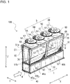
- Fig. 1 is a perspective view of the chilling unit 100 according to Embodiment 1.
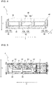
- Fig. 2 is a side view of the chilling unit 100 according to Embodiment 1.
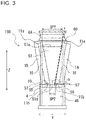
- Fig. 3 is a front view of the chilling unit 100 according to Embodiment 1. It should be noted that Fig. 3 is a front view of the chilling unit 100 as seen in a direction indicated by an outlined in Fig. 1 . An overview of the chilling unit 100 will be described with reference to Figs. 1 to 3 . In the figures including Fig.
- the chilling unit 100 has an elongated shape.
- the chilling unit 100 includes an air heat exchanger 1, a fan 5, and a machine room unit 4 that form a heat-source-side refrigeration cycle circuit.
- the air heat exchanger 1 causes heat exchange to be performed between outside air and refrigerant that flows in the air heat exchanger 1, and operates as an evaporator or a condenser.
- the air heat exchanger 1 includes a plurality of heat transfer tubes 7 and a plurality of fins 8.
- the air heat exchanger 1 is, for example, a parallel-flow heat exchanger, and includes a pair of headers (not illustrated), the heat transfer tubes 7, and the fins 8.
- the heat transfer tubes 7 are, for example, aluminum flat tubes.
- the fins 8 are, for example, corrugated fins.
- the air heat exchanger 1 is not limited to a parallel-flow heat exchanger.
- the air heat exchanger 1 may be, for example, a fin-and-tube heat exchanger in which fins 8 each formed in the shape of a plate are arranged in parallel, and heat transfer tubes 7 penetrate the fins 8.
- the air heat exchanger 1 includes four air heat exchangers 1 that are an air heat exchanger 1A, an air heat exchanger 1B, an air heat exchanger 1C, and an air heat exchanger 1D.
- the air heat exchanger 1A corresponds to a first air heat exchanger;
- the air heat exchanger 1B corresponds to a second air heat exchanger;
- the air heat exchanger 1C corresponds to a third air heat exchanger; and
- the air heat exchanger 1D corresponds to a fourth air heat exchanger.
- the air heat exchanger 1A and the air heat exchanger 1B are provided opposite to each other.
- the air heat exchanger 1A and the air heat exchanger 1B are provided as a pair of air heat exchangers 1 and inclined such that an upper spacing SP1, which is the spacing between upper end portions 11a of the air heat exchangers 1A and 1B that are located far from the machine room unit 4, is greater than a lower spacing SP2, which is the spacing between lower end portions 11b of the air heat exchangers 1A and 1B that are located close to the machine room unit 4. That is, the air heat exchangers 1A and 1B are inclined such that the air heat exchangers 1A and 1B are V-shaped as illustrated in Fig.
- a side panel 50 is provided on one side of the chilling unit 100 such that the side panel 50 covers a space between the air heat exchanger 1A and the air heat exchanger 1C.
- the side panel 50 is a plate-like panel formed in a substantially rectangular shape.
- the side panel 50 extends in the vertical direction (Z-axis direction) and the longitudinal direction (X-axis direction).
- the side panel 50 is provided along the inclination of each air heat exchanger 1 described above.
- another side panel 50 is provided on the other side of the chilling unit 100 such that the side panel 50 covers a space between the air heat exchanger 1B and the air heat exchanger 1D.
- a side panel 51 is provided on the one side of the chilling unit 100 such that a side panel 51 covers the space between the air heat exchanger 1A and the air heat exchanger 1B.
- the side panel 51 is a plate-like panel formed in a substantially trapezoidal shape.
- the side panel 51 is formed such that an upper edge portion 51a of the side panel 51 is longer than a lower edge portion 51b of the side panel 51.
- the side panel 51 extends in the vertical direction (Z-axis direction) and the lateral direction (Y-axis direction).
- the side panel 51 is provided such that in the longitudinal direction (X-axis direction) of the chilling unit 100, the side panel 51 partially covers the end portions of the air heat exchanger 1A and the air heat exchanger 1B. In the longitudinal direction (X-axis direction) of the chilling unit 100, another side panel 51 is also provided on the other side of the chilling unit 100 such that the side panel 51 covers the space between the air heat exchanger 1C and the air heat exchanger 1D.
- the side panel 51 is provided such that in the longitudinal direction (X-axis direction) of the chilling unit 100, the side panel 51 partially covers the end portions of the air heat exchanger 1C and the air heat exchanger 1D.
- a bell mouth 6A, a bell mouth 6B, a bell mouth 6C, and a bell mouth 6D are provided at the top frame 60.
- the fan 5A, the fan 5B, the fan 5C, and the fan 5D are provided inward of the bell mouth 6A, the bell mouth 6B, the bell mouth 6C, and the bell mouth 6D, respectively.
- the chilling unit 100 is a "top-flow type" chilling unit in which the blowing side of each fan 5 faces upward.
- respective fan guards 17 are provided at the air outlets 14 of the bell mouth 6A, the bell mouth 6B, the bell mouth 6C, and the bell mouth 6D.
- the fan 5A, the fan 5B, the fan 5C, and the fan 5D are covered by the respective fan guards 17.
- Fig. 4 is a conceptual diagram schematically illustrating a configuration of the machine room unit 4 as illustrated in Fig. 1 .
- the space occupied by the machine room unit 4 is indicated by dotted lines.
- the configuration of the machine room unit 4 will be described with reference to Figs. 1 and 4 .
- the machine room unit 4 is formed in the shape of an elongated box, and is cuboid.
- the machine room unit 4 includes a cuboid frame 40 and side walls 45 that cover respective spaces between adjacent ones of frame elements included in the frame 40.
- the gatepost 42A, the gatepost 42B, the gatepost 42C, and the gatepost 42D are provided at respective corners of the underframe 41 and extend in a direction orthogonal to the underframe 41.
- the intermediate post 43A and the intermediate post 43B are provided between the gatepost 42A and the gatepost 42C and spaced from each other in the longitudinal direction (X-axis direction) of the underframe 41.
- the intermediate post 43C and the intermediate post 43D are provided between the gatepost 42B and the gatepost 42D and spaced from each other in the longitudinal direction (X-axis direction) of the underframe 41.
- the intermediate post 43A, the intermediate post 43B, the intermediate post 43C, and the intermediate post 43D extend in the direction orthogonal to the underframe 41.
- the top beams 44 are provided above the gatepost 42A, the gatepost 42B, the gatepost 42C, and the gatepost 42D, as well as the intermediate post 43A, the intermediate post 43B, the intermediate post 43C, and the intermediate post 43D.
- the above configuration of the frame 40 is described above by way of example.
- the configuration of the above frame 40 is not limited to the above configuration, and the frame 40 may have any configuration as long as the machine room unit 4 is formed to have a cuboid shape.
- a base 10 is provided on the top beam 44 of the machine room unit 4.
- the base 10 is supported by the gateposts 42 and the intermediate posts 43.
- the air heat exchanger 1A, the air heat exchanger 1B, the air heat exchanger 1C, and the air heat exchanger 1D as described above are provided on the base 10. That is, the air heat exchangers 1 are provided on the top of the machine room unit 4.
- a drain pan 55 is provided on the top of the machine room unit 4.
- the drain pan 55 receives droplets of water discharged from the air heat exchangers 1.
- the drain pan 55 is provided below the air heat exchangers 1 to receive droplets of water that drips down from the air heat exchangers 1.
- the drain pan 55 extends in the longitudinal direction (X-axis direction) of the machine room unit 4.
- the drain pan 55 collects and guides the droplets of water that naturally drips down under gravity from the air heat exchangers 1, as drain water, to a drain outlet (not illustrated).
- the side walls 45 includes first side walls 45a provided at respective end portions of the machine room unit 4 that are located opposite to each other in the longitudinal direction (X-axis direction) and second side walls 45b provided at respective end portions of the machine room unit 4 that are located opposite to each other in the lateral direction (Y-axis direction).
- the first side walls 45a are plate-like side walls that extend in the vertical direction (Z-axis direction) and the lateral direction (Y-axis direction).
- One of the first side walls 45a is located to cover a space located between the gatepost 42A and the gatepost 42B, and the other first side wall 45a is located to cover a space located between the gatepost 42C and the gatepost 42D.
- the second side walls 45b are plate-like side walls that extend in the vertical direction (Z-axis direction) and the longitudinal direction (X-axis direction).
- second wide walls 45b located on one side cover a space located between the gatepost 42A and the intermediate post 43A, a space located between the intermediate post 43A and the intermediate post 43B, and a space located between the intermediate post 43B and the gatepost 42C
- second side walls 45b located on the other side cover a space located between the gatepost 42B and the intermediate post 43C, a space located between the intermediate post 43C and the intermediate post 43D, and a space located between the intermediate post 43D and the gatepost 42D.
- Fig. 5 is a plan view schematically illustrating an internal configuration of the machine room unit 4 as illustrated in Fig. 1 .
- the machine room unit 4 houses a compressor 31, a flow switching device 33, a heat exchanger 3, and a pressure reducing device (not illustrated).
- the compressor 31, the flow switching device 33, the heat exchanger 3, the pressure reducing device, and the air heat exchangers 1 are connected in series by refrigerant pipes to form a refrigerant circuit.
- a plurality of chilling units 100 include respective heat exchangers 3 that are connected in parallel by a water pipe, and a heat transfer fluid in the water pipe is circulated by a pump unit (not illustrated) to flow to a load-side unit (not illustrated) through the heat exchangers 3.
- a plurality of devices installed in the machine room unit 4 include respective control boxes 32.
- the compressor 31 sucks low-temperature and low-pressure refrigerant, compresses the sucked low-temperature and low-pressure refrigerant into high-temperature and high-pressure refrigerant, and discharges the high-temperature and high-pressure refrigerant.
- the flow switching device 33 is, for example, a four-way valve, and switches, under control by a controller (not illustrated), the flows of refrigerant.
- the heat exchanger 3 causes heat exchange to be performed between refrigerant and a heat transfer fluid such as water or antifreeze.
- the pressure reducing device is, for example, an expansion valve, and reduces the pressure of refrigerant.
- the control box 32 houses, for example, a control board that controls the flow switching device 33, a control board that controls the opening degree of the pressure reducing device or other conditions, an inverter board that controls the rotation speed of the compressor 31 or other conditions, etc.
- the machine room unit 4 may include a heater 57.
- the chilling unit 100 In the case where the chilling unit 100 is operated in a cold area, it may present a question how to handle ice that remains on the drain pan 55.
- the heater 57 in the case where the heater 57 is provided in the chilling unit 100, when the chilling unit 100 is operated in the cold area, the heater 57 can melt ice that forms on the drain pan 55, or prevent icing of drain water.
- the heater 57 is provided close to one or some the air heat exchangers 1.
- the heater 57 is provided above the drain pan 55 in such a manner as to extend along the lower end portion 11b of one or some of the air heat exchangers 1 in the longitudinal direction (X-axis direction) of the machine room unit 4.
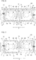
- Fig. 6 is a schematic view illustrating illustrates the shapes and positions of the air heat exchangers 1 in the chilling unit 100 according to Embodiment 1.
- Fig. 6 is a top view of the chilling unit 100, and schematically illustrates the shapes and positions of the air heat exchangers 1 as viewed in a direction from the top frame 60 toward the machine room unit 4, with illustration of some components of the chilling unit 100 omitted. Arrows in Fig. 6 indicate directions in which a worker enters the chilling unit 100.
- the air heat exchanger 1A, the air heat exchanger 1B, the air heat exchanger 1C, and the air heat exchanger 1D are each bent at 90 degrees at a location between a middle portion and one end portion of each heat transfer tube 7 in the extending direction thereof. That is, the air heat exchanger 1A, the air heat exchanger 1B, the air heat exchanger 1C, and the air heat exchanger 1D are each L-shaped as viewed in the direction from the top frame 60 toward the machine room unit 4.
- the above heat transfer tubes 7 protrude from an end portion of the short-side portion 1AS of the air heat exchanger 1A.
- the heat transfer tubes 7 protruding from the end portion of the short-side portion 1AS do not penetrate the fins 8 and are exposed to the outside.
- the heat transfer tubes 7 protruding from the end portion of the short-side portion 1AS are linearly formed.
- an end portion of one of the heat transfer tubes 7 that is an end portion corresponding to the inlet for refrigerant is connected with a header pipe 12
- an end portion of another one of heat transfer tubes 7 that is an end portion corresponding to the outlet for refrigerant is connected with a header pipe 13.
- One of the header pipe 12 and the header pipe 13 may not be a header pipe but may be a distributor.
- the air heat exchanger 1B has a long-side portion 1BL, a corner portion 1BE, and a short-side portion 1BS.
- the long-side portion 1BL is a portion of the air heat exchanger 1B that is longer than the short-side portion 1BS in the direction in which associated heat transfer tubes 7 extend.
- a heat-exchanger end portion 1BT is an end portion of the long-side portion 1BL and is also an end portion of the air heat exchanger 1B in the longitudinal direction (X-axis direction) of the machine room unit 4.
- the corner portion 1BE is an L-shaped portion of the air heat exchanger 1B.
- the corner portion 1BE is a second corner portion located between the long-side portion 1BL and the short-side portion 1BS.
- the short-side portion 1BS is a portion of the air heat exchanger 1B that is shorter than the long-side portion 1BL in the direction in which the heat transfer tubes 7 extend.
- the above heat transfer tubes 7 protrude from an end portion of the short-side portion 1BS of the air heat exchanger 1B.
- the heat transfer tubes 7 protruding from the end portion of the short-side portion 1BS do not penetrate the fins 8 and are exposed to the outside.
- the heat transfer tubes 7 protruding from the end portion of the short-side portion 1BS are linearly formed.
- an end portion of one of the heat transfer tubes 7 that is an end portion corresponding to the inlet for refrigerant is connected with the header pipe 12
- an end portion of another one of the heat transfer tubes 7 that is an end portion corresponding to the outlet for refrigerant is connected with the header pipe 13.
- One of the header pipe 12 and the header pipe 13 may not be a header pipe but may be a distributor.
- the air heat exchanger 1C has a long-side portion 1CL, a corner portion 1CE, and a short-side portion 1CS.
- the long-side portion 1CL is a portion of the air heat exchanger 1C that is longer than the short-side portion 1CS in the direction in which the heat transfer tubes 7 extend.
- a heat-exchanger end portion 1CT is an end portion of the long-side portion 1CL and is also an end portion of the air heat exchanger 1C in the longitudinal direction (X-axis direction) of the machine room unit 4.
- the corner portion 1CE is an L-shaped portion of the air heat exchanger 1C.
- the corner portion 1CE is a third corner portion located between the long-side portion 1CL and the short-side portion 1CS.
- the short-side portion 1CS is a portion of the air heat exchanger 1C that is shorter than the long-side portion 1CL in the direction in which the heat transfer tubes 7 extend.
- the above heat transfer tubes 7 protrude from an end portion of the short-side portion 1CS of the air heat exchanger 1C.
- the heat transfer tubes 7 protruding from the end portion of the short-side portion 1CS do not penetrate the fins 8 and are exposed to the outside.
- the heat transfer tubes 7 protruding from the end portion of the short-side portion 1CS are linearly formed.
- an end portion of one of the heat transfer tubes 7 that is an end portion corresponding to the inlet for refrigerant is connected with the header pipe 12
- an end portion of another one of the heat transfer tubes 7 that is an end portion corresponding to the outlet for refrigerant is connected with the header pipe 13.
- One of the header pipe 12 and the header pipe 13 may not be a header pipe but may be a distributor.
- the air heat exchanger 1D has a long-side portion 1DL, a corner portion 1DE, and a short-side portion 1DS.
- the long-side portion 1DL is a portion of the air heat exchanger 1D that is longer than the short-side portion 1DS in the direction in which the heat transfer tubes 7 extend.
- a heat-exchanger end portion 1DT is an end portion of the long-side portion 1DL and is also an end portion of the air heat exchanger 1D in the longitudinal direction (X-axis direction) of the machine room unit 4.
- the corner portion 1DE is an L-shaped portion of the air heat exchanger 1D.
- the corner portion 1DE is a fourth corner portion located between the long-side portion 1DL and the short-side portion 1DS.
- the short-side portion 1DS is a portion of the air heat exchanger 1D that is shorter than the long-side portion 1DL in the direction in which the heat transfer tubes 7 extend.
- the above heat transfer tubes 7 protrude from an end portion of the short-side portion 1DS of the air heat exchanger 1D.
- the heat transfer tubes 7 protruding from the end portion of the short-side portion 1DS do not penetrate the fins 8 and are exposed to the outside.
- the heat transfer tubes 7 protruding from the end portion of the short-side portion 1DS are linearly formed.
- an end portion of one of the heat transfer tubes 7 that is end end portion corresponding to the inlet for refrigerant is connected with the header pipe 12
- an end portion of another one of the heat transfer tubes 7 that is an end portion corresponding to the outlet for refrigerant is connected with the header pipe 13.
- One of the header pipe 12 and the header pipe 13 may not be a header pipe but may be a distributor.
- Air Heat Exchanger 1A and Air Heat Exchanger 1B Air Heat Exchanger 1A and Air Heat Exchanger 1B
- the air heat exchanger 1A and the air heat exchanger 1B are opposite to each other in the lateral direction (Y-axis direction) of the machine room unit 4. More specifically, in the lateral direction (Y-axis direction) of the machine room unit 4, an end portion of the short-side portion 1AS of the air heat exchanger 1A is opposite to an end portion of the long-side portion 1BL of the air heat exchanger 1B, and an end portion of the short-side portion 1BS of the air heat exchanger 1B is opposite to an end portion of the long-side portion 1AL of the air heat exchanger 1A.
- the air heat exchanger 1A and the air heat exchanger 1B are arranged symmetrical with respect to a point.
- the end portion of the short-side portion 1AS of the air heat exchanger 1A is located close to a unit end portion 4D of the chilling unit 100, and the end portion of the short-side portion 1BS of the air heat exchanger 1B is located close to a middle portion 4C of the chilling unit 100.
- the header pipe 12 and the header pipe 13 connected to the air heat exchanger 1A are located close to the unit end portion 4D of the chilling unit 100, and the header pipe 12 and the header pipe 13 connected to the air heat exchanger 1B are located close to the middle portion 4C of the chilling unit 100.
- the longitudinal direction (X-axis direction) of the chilling unit 100 is the same as that of the machine room unit 4.
- the middle portion 4C of the chilling unit 100 is located at the same position as a portion of the machine room unit 4 that is included in the middle portion 4C.
- the unit end portion 4D of the chilling unit 100 is located at the same position as a portion of the machine room unit 4 that is included in the unit end portion 4D.
- the long-side portion 1AL of the air heat exchanger 1A is parallel to the long-side portion 1BL of the air heat exchanger 1B in the longitudinal direction (X-axis direction) of the machine room unit 4.
- the heat-exchanger end portion 1AT of the long-side portion 1AL of the air heat exchanger 1A is located close to the middle portion 4C of the chilling unit 100.
- the heat-exchanger end portion 1BT of the long-side portion 1BL of the air heat exchanger 1B is located close to the unit end portion 4D of the chilling unit 100.
- the air heat exchanger 1A and the air heat exchanger 1B are L-shaped and the orientations of the short-side portion 1AS and the long-side portion 1AL of the air heat exchanger 1A are reverse to those of the short-side portion 1BS and the long-side portion 1BL of the air heat exchanger 1B in the longitudinal direction (X-axis direction) of the machine room unit. Accordingly, the air heat exchanger 1A and the air heat exchanger 1B are arranged in the shape of a quadrangle in a horizontal plane. That is, the air heat exchanger 1A and the air heat exchanger 1B, which are a pair of air heat exchangers 1, are arranged in the shape of a quadrangle as viewed in plan view.
- the air heat exchanger 1C and the air heat exchanger 1D are opposite to each other in the lateral direction (Y-axis direction) of the machine room unit 4. More specifically, in the lateral direction (Y-axis direction) of the machine room unit 4, the end portion of the short-side portion 1CS of the air heat exchanger 1C is located opposite to the end portion of the long-side portion 1 DL of the air heat exchanger 1D, and the end portion of the short-side portion 1DS of the air heat exchanger 1D is located opposite to the end portion of the long-side portion 1CL of the air heat exchanger 1C.
- the air heat exchanger 1C and the air heat exchanger 1D are arranged symmetrical with respect to a point.
- the end portion of the short-side portion 1CS of the air heat exchanger 1C is located close to another unit end portion 4D of the chilling unit 100, and the end portion of the short-side portion 1DS of the air heat exchanger 1D is located close to the middle portion 4C of the chilling unit 100.
- the header pipe 12 and the header pipe 13 connected to the air heat exchanger 1C are located close to the above unit end portion 4D of the chilling unit 100, and the header pipe 12 and the header pipe 13 connected to the air heat exchanger 1D are located close to the middle portion 4C of the chilling unit 100.
- the long-side portion 1CL of the air heat exchanger 1C is parallel to the long-side portion 1DL of the air heat exchanger 1D in the longitudinal direction (X-axis direction) of the machine room unit 4.
- the heat-exchanger end portion 1CT of the long-side portion 1CL of the air heat exchanger 1C is located close to the middle portion 4C of the chilling unit 100.
- the heat-exchanger end portion 1 DT of the long-side portion 1DL of the air heat exchanger 1D is located close to the unit end portion 4D of the chilling unit 100.
- the air heat exchanger 1C and the air heat exchanger 1D are L-shaped and the orientations of the short-side portion 1CS and the long-side portion 1CL of the air heat exchanger 1C are reverse to the short-side portion 1DS and the long-side portion 1DL of the air heat exchanger 1D in the longitudinal direction (X-axis direction) of the machine room unit.
- the air heat exchanger 1C and the air heat exchanger 1D are arranged in the shape of a quadrangle in the horizontal plane. That is, the air heat exchanger 1C and the air heat exchanger 1D, which are a pair of air heat exchangers 1, are arranged in the shape of a quadrangle as viewed in plan view.
- the corner portion 1AE that is the first corner portion is located close to the unit end portion 4D that is one end portion of the machine room unit 4, and the corner portion 1BE that is the second corner portion is located close to the middle portion 4C of the machine room unit 4.
- the air heat exchanger 1A and the air heat exchanger 1B are arranged in the shape of a quadrangle in the horizontal plane.
- the corner portion 1CE that is the third corner portion is located close to the unit end portion 4D that is the other end portion of the machine room unit 4, and the corner portion 1DE that is the fourth corner portion is located close to the middle portion 4C of the machine room unit 4.
- the air heat exchanger 1C and the air heat exchanger 1D are arranged in the shape of a quadrangle in the horizontal plane. From each of the heat-exchanger end portion 1BT and the heat-exchanger end portion 1DT, heat transfer tubes 7 do not extend. That is, heat transfer tubes 7 that protrude from a fin 8 corresponding to an outermost one of the fins 8 in a direction where the fins 8 are arranged and that extend linearly in the lateral direction (Y-axis direction) do not extend from each of the heat-exchanger end portions 1BT and 1DT.
- Fig. 7 is a schematic view illustrating a modification of the chilling unit 100 according to Embodiment 1.
- the chilling unit 100 according to the modification includes a partition plate 15.
- the partition plate 15 forms a wall that isolates the air heat exchangers 1A and 1B from the air heat exchangers 1C and 1D in the longitudinal direction (X-axis direction) of the chilling unit 100. That is, the partition plate 15 is provided between two pairs of air heat exchangers 1 arranged side by side in the longitudinal direction (X-axis direction), and defines a wall.
- the partition plate 15 is located between the air heat exchangers 1A and 1B and the air heat exchangers 1C and 1D.
- the partition plate 15 is provided at a center position of each of the machine room unit 4 and the chilling unit 100 in the longitudinal direction (X-axis direction).
- the "center position” means not only the center position of each of the machine room unit 4 and the chilling unit 100 in the longitudinal direction (X-axis direction) but also a substantially center position close to the center position.
- the partition plate 15 forms a wall that extends between the above side panels 50, that is, the side panel 50 provided between the air heat exchanger 1A and the air heat exchanger 1C and the side panel 50 provided between the air heat exchanger 1B and the air heat exchanger 1D.
- a first space SA and a second space SB are divided spaces provided by the partition plate 15.
- the partition plate 15 isolates the first space SA and the second space SB from each other, and the first space SA being defined by one pair of air heat exchangers 1, the second space SB being defined by the other pair of air heat exchangers 1.
- the first space SA is defined by the air heat exchanger 1A, the air heat exchanger 1B, the side panel 50, the side panel 51, and the partition plate 15.
- the second space SB is defined by the air heat exchanger 1C, the air heat exchanger 1D, the side panel 50, the side panel 51, and the partition plate 15.
- the first space SA and the second space SB are isolated from each other by the partition plate 15 as described above.
- the air heat exchangers 1A and 1B provided as the above one pair and the air heat exchangers 1C and 1D provided as the above other pair can be operated in different operation modes.
- outside air is caused by the fans 5 to pass through the air heat exchangers 1, whereby the outside air exchanges heat with refrigerant that flows in the air heat exchangers 1.
- the air that has exchanged heat with the refrigerant is discharged by the fans 5 from the top of the chilling unit 100.
- the operation is switched between a cooling operation in which one or some of the air heat exchangers 1 operate as condensers and the heat exchanger 3 operates as an evaporator and a heating operation in which the air heat exchangers 1 operate as evaporators and the heat exchanger 3 operates as a condenser.
- a heat transfer fluid cooled at the heat exchanger 3 is provided, and for example, the cooled heat transfer fluid is supplied to the load-side unit (not illustrated) to cool air in a load side (indoor side), thereby cooling the indoor space.
- a heat transfer fluid heated at the heat exchanger 3 is provided, and for example, the heated heat transfer fluid is supplied to the load-side unit (not illustrated) to heat air in the load side (indoor side), thereby heating the indoor space.
- the heat-exchanger end portion 1BT of the long-side portion 1BL of at least one air heat exchanger 1 of a pair of air heat exchangers 1 and the heat-exchanger end portion 1DT of the long-side portion 1DL of at least one air heat exchanger 1 of a pair of air heat exchangers 1 are provided at the respective unit end portions 4D of the machine room unit 4, which are located as the end portions thereof in the longitudinal direction. From each of the heat-exchanger end portion 1BT and the heat-exchanger end portion 1DT, heat transfer tubes 7 do not extend.
- the first space SA and the second space SB are divided spaces provided by the partition plate 15.
- the air heat exchangers 1A and 1B provided as one pair and the air heat exchangers 1C and 1D provided as another pair can be operated in different operation modes.
- the chilling unit 100 since the air heat exchangers 1 located in the first space SA and the air heat exchangers 1 located in the second space SB are operated in different operation modes, for example, two systems can individually perform respective defrost operations. Therefore, the chilling unit 100 can reduce a decrease in water temperature, as compared with the case where only the defrost operation can be performed, that is, the systems cannot perform different operations at the same time.
- the air heat exchanger 1A, the air heat exchanger 1B, the air heat exchanger 1C, and the air heat exchanger 1D are each connected with the associated header pipes 12 and 13 at the end portion of each air heat exchanger in the direction in which the associated heat transfer tubes 7 extend.
- Fig. 10 is a schematic view illustrating a modification of the chilling unit 100A according to Embodiment 2.
- the chilling unit 100A according to the modification includes the partition plate 15.
- the heat transfer tubes 7 of a pair of air heat exchangers 1 disposed in the lateral direction do not extend in such a manner to cover the front side of the chilling unit 100A.
- the chilling unit 100A not both the two systems of header pipes 12 and 13 at a pair of heat exchangers 1 or not both the distributors at the pair of air heat exchangers 1 are provided on the front side of the chilling unit where the worker enters the chilling unit. It is therefore possible to provide a sufficient space for the worker to enter the chilling unit 100A on the front side of the chilling unit 100A. The worker is thus able to easily enter and exit the space defined by the air exchangers.
- Air Heat Exchanger 1A and Air Heat Exchanger 1B Air Heat Exchanger 1A and Air Heat Exchanger 1B
- the air heat exchanger 1A and the air heat exchanger 1B are opposite to each other in the lateral direction (Y-axis direction) of the machine room unit 4. More specifically, in the lateral direction (Y-axis direction) of the machine room unit 4, an end portion of the short-side portion 1AS of the air heat exchanger 1A is opposite to an end portion of the long-side portion 1BL of the air heat exchanger 1B, and an end portion of the short-side portion 1BS of the air heat exchanger 1B is opposite to an end portion of the long-side portion 1AL of the air heat exchanger 1A.
- the air heat exchanger 1A and the air heat exchanger 1B are arranged symmetrical with respect to a point.
- the long-side portion 1AL of the air heat exchanger 1A is parallel to the long-side portion 1BL of the air heat exchanger 1B in the longitudinal direction (X-axis direction) of the machine room unit 4.
- the heat-exchanger end portion 1AT of the long-side portion 1AL of the air heat exchanger 1A is located close to the middle portion 4C of the chilling unit 100B.
- the heat-exchanger end portion 1BT of the long-side portion 1BL of the air heat exchanger 1B is located close to the unit end portion 4D of the chilling unit 100B.
- the air heat exchanger 1A and the air heat exchanger 1B which are L-shaped, are disposed such that the orientations of the short-side portion 1AS and the long-side portion 1AL of the air heat exchanger 1A are reverse to those of the short-side portion 1BS and the long-side portion 1BL of the air heat exchanger 1B in the longitudinal direction (X-axis direction) of the machine room unit. Accordingly, the air heat exchanger 1A and the air heat exchanger 1B are arranged in the shape of a quadrangle in the horizontal plane.
- the air heat exchanger 1A and the air heat exchanger 1B, which are provided as a pair of air heat exchangers 1, are arranged in the shape of a quadrangle as viewed in plan view.
- the air heat exchanger 1C and the air heat exchanger 1D are opposite to each other in the lateral direction (Y-axis direction) of the machine room unit 4. More specifically, in the lateral direction (Y-axis direction) of the machine room unit 4, the end portion of the short-side portion 1CS of the air heat exchanger 1C is opposite to the end portion of the long-side portion 1DL of the air heat exchanger 1D, and the end portion of the short-side portion 1DS of the air heat exchanger 1D is opposite to the end portion of the long-side portion 1CL of the air heat exchanger 1C.
- the air heat exchanger 1C and the air heat exchanger 1D are arranged symmetrical with respect to a point.
- the end portion of the short-side portion 1CS of the air heat exchanger 1C is located close to the middle portion 4C of the chilling unit 100B, and the end portion of the short-side portion 1DS of the air heat exchanger 1D is located close to an associated unit end portion 4D of the chilling unit 100B.
- the header pipes 12 and 13 connected to the air heat exchanger 1C are located close to the middle portion 4C of the chilling unit 100B, and the header pipes 12 and 13 connected to the air heat exchanger 1D are located close to the unit end portion 4D of the chilling unit 100B.
- the long-side portion 1CL of the air heat exchanger 1C is parallel to the long-side portion 1DL of the air heat exchanger 1D in the longitudinal direction (X-axis direction) of the machine room unit 4.
- the heat-exchanger end portion 1CT of the long-side portion 1CL of the air heat exchanger 1C is located close to the unit end portion 4D of the chilling unit 100B.
- the heat-exchanger end portion 1DT of the long-side portion 1DL of the air heat exchanger 1D is located close to the middle portion 4C of the chilling unit 100B.
- the air heat exchangers 1 are arranged symmetrical with respect to a point in shape and position. More specifically, the air heat exchanger 1A and the air heat exchanger 1D are arranged symmetrical with respect to a point. Furthermore, the air heat exchanger 1B and the air heat exchanger 1C are arranged symmetrical with respect to a point. The air heat exchangers 1A and 1B and the air heat exchangers 1C and 1D are arranged to have the same shape and on the opposite sides with respect to the middle position of the chilling unit 100B in the longitudinal direction (X-axis direction).
- At least the air heat exchanger 1B which is at least one air heat exchanger 1 of a pair of air heat exchangers 1 disposed in the lateral direction (Y-axis direction) of the machine room unit 4, has the heat-exchanger end portion 1BT of the long-side portion 1BL at one end portion of the machine room unit 4 in the longitudinal direction.
- At least the air heat exchanger 1C which is at least one air heat exchanger 1 of a pair of air heat exchangers 1 disposed in the lateral direction of the machine room unit 4, has the heat-exchanger end portion 1CT of the long-side portion 1CL at another end portion of the machine room unit 4 in the longitudinal direction.
- Fig. 12 is a schematic view illustrating a modification of the chilling unit 100B according to Embodiment 3.
- the chilling unit 100B according to the modification includes the partition plate 15.
- the corner portion 1AE that is the first corner portion is provided close to the unit end portion 4D corresponding to the other end portion of the machine room unit 4, and the corner portion 1BE that is the second corner portion is provided close to the middle portion 4C of the machine room unit 4.
- the air heat exchanger 1A and the air heat exchanger 1B are arranged in the shape of a quadrangle in the horizontal plane.
- the corner portion 1CE that is the third corner portion is provided close to the middle portion 4C of the machine room unit 4
- the corner portion 1 DE that is the fourth corner portion is provided close to the unit end portion 4D corresponding to the other end portion of the machine room unit 4.
- Fig. 13 is a schematic view illustrating the shapes and positions of the air heat exchangers 1 in a chilling unit 100C according to Embodiment 4.
- Fig. 13 is a top view of the chilling unit 100C and schematically illustrates the shapes and positions of the air heat exchangers 1 as viewed in the direction from the top frame 60 toward the machine room unit 4, with illustration of some components omitted.
- Embodiment 4 components that are the same as those of any of the chilling units 100 as illustrated in Figs. 1 to 12 are denoted by the same reference signs, and their descriptions will thus be omitted.
- the chilling unit 100C according to Embodiment 4 differs from the chilling unit 100 according to Embodiment 1 in the shapes and positions of the air heat exchangers 1.
- the chilling unit 100C will be described by referring mainly to the differences between the air heat exchangers 1 in the chilling unit 100C and those according to Embodiment 1, and illustration and descriptions of configurations other than configurations related to the differences will be omitted.
- the air heat exchanger 1A and the air heat exchanger 1D are each bent at 90 degrees at a location between the middle portion and one end portion of each of associated heat transfer tubes 7 in the extending direction thereof. That is, the air heat exchanger 1A and the air heat exchanger 1D are L-shaped as viewed in the direction from the top frame 60 toward the machine room unit 4.
- the air heat exchanger 1B and the air heat exchanger 1C are each formed in the shape of a flat plate. That is, the air heat exchanger 1B and the air heat exchanger 1C are each I-shaped as viewed in the direction orthogonal to the heat transfer tubes 7.
- the air heat exchanger 1A has the long-side portion 1AL, the corner portion 1AE, and the short-side portion 1AS.
- the air heat exchanger 1B has the long-side portion 1BL.
- the air heat exchanger 1C has the long-side portion 1CL.
- the air heat exchanger 1D has the long-side portion 1DL, the corner portion 1DE, and the short-side portion 1DS.
- Air Heat Exchanger 1A and Air Heat Exchanger 1B Air Heat Exchanger 1A and Air Heat Exchanger 1B
- the air heat exchanger 1A and the air heat exchanger 1B are opposite to each other in the lateral direction (Y-axis direction) of the machine room unit 4. More specifically, in the lateral direction (Y-axis direction) of the machine room unit 4, the end portion of the short-side portion 1AS of the air heat exchanger 1A is opposite to the end portion of the long-side portion 1BL of the air heat exchanger 1B.
- the end portion of the short-side portion 1AS of the air heat exchanger 1A is located close to the unit end portion 4D of the chilling unit 100C.
- the header pipe 12 and the header pipe 13 connected to the air heat exchanger 1A are located close to one unit end portion 4D of the chilling unit 100C, and the header pipe 12 and the header pipe 13 connected to the air heat exchanger 1B are located close to the middle portion 4C of the chilling unit 100C.
- the long-side portion 1AL of the air heat exchanger 1A is parallel to the long-side portion 1BL of the air heat exchanger 1B in the longitudinal direction (X-axis direction) of the machine room unit 4.
- the heat-exchanger end portion 1AT of the long-side portion 1AL of the air heat exchanger 1A is located close to the middle portion 4C of the chilling unit 100C.
- the heat-exchanger end portion 1 BT of the long-side portion 1BL of the air heat exchanger 1 B is located close to the unit end portion 4D of the chilling unit 100C.
- the end portion of the short-side portion 1DS of the air heat exchanger 1D is located close to the unit end portion 4D of the chilling unit 100C.
- the header pipe 12 and the header pipe 13 connected to the air heat exchanger 1D are located close to the other unit end portion 4D of the chilling unit 100C, and the header pipe 12 and the header pipe 13 connected to the air heat exchanger 1C are located close to the middle portion 4C of the chilling unit 100C.
- the air heat exchangers 1 are arranged symmetrical in shape and position with respect to a point. More specifically, the air heat exchanger 1A and the air heat exchanger 1D are arranged symmetrical with respect to a point. Furthermore, the air heat exchanger 1B and the air heat exchanger 1C are arranged symmetrical with respect to a point.
- the heat-exchanger end portion 1BT of the long-side portion 1BL is provided at one end portion of the machine room unit 4 in the longitudinal direction.
- the heat-exchanger end portion 1CT of the long-side portion 1CL is provided at the other end portion of the machine room unit 4 in the longitudinal direction.
- Two pairs of air heat exchangers 1 are arranged side by side in the longitudinal direction (X-axis direction) of the machine room unit 4. That is, the air heat exchangers 1A and 1B provided as one pair and the air heat exchangers 1C and 1D provided as another pair are arranged side by side in the longitudinal direction (X-axis direction) of the machine room unit 4. From each of the heat-exchanger end portion 1BT and the heat-exchanger end portion 1CT, heat transfer tubes 7 do not extend.
- heat transfer tubes 7 do not extend: the heat transfer tubes 7 that protrude from the fin 8 corresponding to the outermost one of the fins 8 in the direction in which the fins 8 are arranged and that extend linearly in the lateral direction (Y-axis direction) do not extend from each of the heat-exchanger end portion 1BT and the heat-exchanger end portion 1CT.
- Fig. 14 is a schematic view illustrating a modification of the chilling unit 100C according to Embodiment 4.
- the chilling unit 100C according to the modification includes the partition plate 15.
- the chilling unit 100C not both the two systems of header pipes 12 and 13 or both the distributors at a pair of air heat exchangers 1 are provided on the front side of the chilling unit where the worker enters the chilling unit. It is therefore possible to provide a sufficient space for the worker to enter the chilling unit 100C on the front side of the chilling unit 100C. The worker is thus able to easily enter and exit the space defined by the air exchangers. The ease of maintenance of the chilling unit 100C is improved. Furthermore, on the front side of the chilling unit 100C, the air heat exchanger 1B and the air heat exchanger 1C are not bend in the lateral direction. Thus, the space on the front side the chilling unit 100C is not blocked by the air heat exchanger 1B.
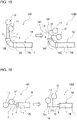
- Fig. 15 is an enlarged view of an end portion of the air heat exchanger 1 in a chilling unit 100D according to Embodiment 5.
- Fig. 16 is an enlarged view of an end portion of another air heat exchanger 1 in the chilling unit 100D according to Embodiment 5.
- Each of Figs. 15 and 16 illustrates an end portion of the air heat exchanger 1 of the chilling unit 100 on the left side of the figure and an end portion of the air heat exchanger 1 of the chilling unit 100D on the right side of the figure.
- the air heat exchanger 1A is illustrated as an air heat exchanger 1, the air heat exchanger 1 is not limited to the air heat exchanger 1A but may be the air heat exchanger 1B, the air heat exchanger 1C, or the air heat exchanger 1D.
- the chilling unit 100 may be the chilling unit 100A, the chilling unit 100B, or the chilling unit 100C. It should be noted that regarding Embodiment 5, components that are the same as those of any of the chilling units 100 as illustrated in Figs. 1 to 14 will be denoted by the same reference signs and their descriptions will thus omitted.
- the chilling unit 100D according to Embodiment 5 includes heat transfer tubes 7A that differ in shape from the heat transfer tubes 7 of the chilling unit 100 according to Embodiment 1.
- the chilling unit 100D will be described by referring mainly to the differences between the heat transfer tubes 7A and hose according to Embodiment 1, and illustration and descriptions of configurations other than configurations related to the differences will thus be omitted.
- Each heat transfer tube 7A has a bent portion 7A1 that is an end portion of the heat transfer tube 7A in the direction in which the heat transfer tube 7A extends and that has a tube passage bent at an exposed portion that does not penetrate the fins 8. It is preferable that the heat transfer tubes 7A be aluminum flat tubes.
- the bent portion 7A1 is L-shaped, for example, as viewed in plan view. However, the shape of the bent portion 7A1 is not limited to the L-shape.
- Each heat transfer tube 7A has the bent portion 7A1, which is an end portion thereof in a direction in which the heat transfer tube 7A and has a tube passage that is bent to the exposed portion that does not penetrate the fins 8. Since each heat transfer tube 7A is bent, it is possible to provide a sufficient space for the worker to enter and exit the chilling unit 100D can be provided on the front side of the chilling unit 100D. The worker is thus able to easily enter and exit the space defined by the air heat exchangers 1, and the ease of the maintenance of the chilling unit 100D is improved. Furthermore, since each heat transfer tube 7A is bent, the air heat exchangers 1 of the chilling unit 100D can be elongated in the longitudinal direction (X-axis direction). It is therefore possible to provide increase the area of the heat exchange portion where heat exchange is performed between air and refrigerant, and improve the heat exchange performance of the chilling unit 100, as compared with the case where the chilling unit 100 does not employ the heat transfer tubes 7A.
Landscapes
- Engineering & Computer Science (AREA)
- Mechanical Engineering (AREA)
- General Engineering & Computer Science (AREA)
- Physics & Mathematics (AREA)
- Thermal Sciences (AREA)
- Chemical & Material Sciences (AREA)
- Combustion & Propulsion (AREA)
- Geometry (AREA)
- Other Air-Conditioning Systems (AREA)
Abstract
Description
- The present disclosure relates to a chilling unit that forms, for example, an air-conditioning apparatus, a heat-pump water heater, or a refrigeration apparatus.
- In the past, chilling units have been proposed each of which includes a heat exchange unit that houses an air heat exchanger and a fan and a machine room that houses a compressor and a heat exchanger (see, for example, Patent Literature 1).
- Patent Literature 1:
Japanese Patent No. 5760049 - In the case of performing maintenance on a chilling unit having an elongated shape, a worker enters a heat exchange portion of the chilling unit from an end face thereof that corresponds to a front side of the chilling unit in a longitudinal direction thereof. However, the chilling unit described in
Patent Literature 1 has an L-shaped bent portion at its end portion in the longitudinal direction, and heat transfer tubes of a pair of air heat exchangers disposed in the lateral direction extend on the front side of the chilling unit. Therefore, in the chilling unit described inPatent Literature 1, two systems of header pipes or distributors associated with a pair of air heat exchangers are disposed at part of the chilling unit through which the worker enters the front side of the chilling unit. Thus, the worker does not easily enter or leave the heat exchange portion, and thus does not easily perform maintenance on the chilling unit. - The present disclosure is applied to solve the above problem, and relates to a chilling unit that allows a worker to easily enter and exit a space defined by air heat exchangers, whereby the ease of maintenance of a heat exchange portion of the chilling unit is improved.
- A chilling unit according to an embodiment of the present disclosure includes: a plurality of air heat exchangers each including a plurality of heat transfer tubes and a plurality of fins; and a machine room unit which is formed in the shape of an elongated box and on which the plurality of air heat exchangers are provided. The plurality of air heat exchangers each have a long-side portion that extends in a longitudinal direction of the machine room unit. The plurality of air heat exchangers include two pairs of air heat exchangers, the pairs of air heat exchangers are arranged side by side in the longitudinal direction, and the air heat exchangers of each of the pairs of air heat exchangers are opposite to each other in a lateral direction of the machine room unit. The air heat exchangers of each pair are inclined such that a spacing between upper end portions of the air heat exchangers that are located far from the machine room unit is greater than a spacing between lower end portions of the air heat exchangers that are located close to the machine room unit. In each pair, the long-side portion of at least one of the air heat exchangers has a heat-exchanger end portion that is located at one of unit end portions of the machine room unit in the longitudinal direction, and from the heat-exchanger end portion of the long-side portion of the at least one of the air heat exchangers, heat transfer tubes that protrude from an outermost one of the plurality of fins in a direction in which the plurality of fins are arranged and that extend linearly in the lateral direction do not extend.
- According to an embodiment of the present disclosure, in the chilling unit, the heat-exchanger end portion of the long-side portion of at least one air heat exchanger of a pair of air heat exchangers is provided at one of the unit end portions of the machine room unit in the longitudinal direction (X-axis direction). From the heat-exchanger end portion, heat transfer tubes that protrude from an outermost one of the fins in the direction where the fins are arranged and that extend linearly in the lateral direction (Y-axis direction) do not extend. Therefore, in the chilling unit, the heat transfer tubes of at least one of a pair of air heat exchangers provided in the lateral direction do not extend to cover the front side of the chilling unit. Thus, in the chilling unit, not both two systems of header pipes or not both distributors at a pair of air heat exchangers are disposed on the front side of the chilling unit where the worker enters the chilling unit. It is therefore possible to provide a sufficient space for the worker to enter the chilling unit on the front side of the chilling unit. The worker is thus able to easily enter and exit a space defined by air exchangers and corresponding to the heat exchange part of the chilling unit. The ease of maintenance of the chilling unit is improved.
-
- [
Fig. 1] Fig. 1 is a perspective view of a chilling unit according toEmbodiment 1. - [
Fig. 2] Fig. 2 is a side view of the chilling unit according to Embodiment 1. - [
Fig. 3] Fig. 3 is a front view of the chilling unit according to Embodiment 1. - [
Fig. 4] Fig. 4 is a conceptual diagram schematically illustrating a configuration of a machine room unit as illustrated inFig. 1 . - [
Fig. 5] Fig. 5 is a plan view schematically illustrating an internal configuration of the machine room unit as illustrated inFig. 1 . - [
Fig. 6] Fig. 6 is a schematic view illustrating the shapes and positions of air heat exchangers in the chilling unit according toEmbodiment 1. - [
Fig. 7] Fig. 7 is a schematic view illustrating a modification of the chilling unit according toEmbodiment 1. - [
Fig. 8] Fig. 8 is a schematic view illustrating the shapes and positions of air heat exchangers in a chilling unit according to a comparative example. - [
Fig. 9] Fig. 9 is a schematic view illustrating the shapes and positions of air heat exchangers in a chilling unit according to Embodiment 2. - [
Fig. 10] Fig. 10 is a schematic view illustrating a modification of the chilling unit according to Embodiment 2. - [
Fig. 11] Fig. 11 is a schematic view illustrating the shapes and positions of air heat exchangers in a chilling unit according toEmbodiment 3. - [
Fig. 12] Fig. 12 is a schematic view illustrating a modification of the chilling unit according toEmbodiment 3. - [
Fig. 13] Fig. 13 is a schematic view illustrating the shapes and positions of air heat exchangers in a chilling unit according toEmbodiment 4. - [
Fig. 14] Fig. 14 is a schematic view illustrating a modification of the chilling unit according toEmbodiment 4. - [
Fig. 15] Fig. 15 is an enlarged view of an end portion of an air heat exchanger in a chilling unit according toEmbodiment 5. - [
Fig. 16] Fig. 16 is an enlarged view of an end portion of another air heat exchanger in the chilling unit according toEmbodiment 5. - A
chilling unit 100 according to each of embodiments will be described with reference to the drawings or other illustrations. In figures includingFig. 1 that will be referred to below, the relative dimensions, shapes, and other features of various components may differ from actual ones. In each of the figures, components that are the same as or equivalent to a previous figure or previous figures are denoted by the same reference sings, and the same is true of the entire text of the specification. With respect to the embodiments, in order that they be easily understood, terms related to directions (such as "upper", "lower", "right", "left", front", and "rear") are used as appropriate. However, these terms are used only for explanation, that is, they do not limit the locations or orientations of devices or components. -
Fig. 1 is a perspective view of thechilling unit 100 according toEmbodiment 1.Fig. 2 is a side view of thechilling unit 100 according toEmbodiment 1.Fig. 3 is a front view of thechilling unit 100 according to Embodiment 1. It should be noted thatFig. 3 is a front view of thechilling unit 100 as seen in a direction indicated by an outlined inFig. 1 . An overview of thechilling unit 100 will be described with reference toFigs. 1 to 3 . In the figures includingFig. 1 , the X-axis represents a longitudinal direction of thechilling unit 100, the Y-axis represents a width direction or a lateral direction of thechilling unit 100, and the Z-axis represents a height direction of thechilling unit 100. The positional relationship between individual components (for example, their positional relationship in the height direction) described in the following description is basically a positional relationship between the components that is established when thechilling unit 100 is installed in a usable state. - The
chilling unit 100 is used as a heat source apparatus of a chiller. Thechilling unit 100 is supplied with a heat transfer fluid, such as water or antifreeze, from a load-side unit (not illustrated). The heat transfer fluid is cooled or heated in thechilling unit 100 and then supplied to the load-side unit. Thechilling unit 100 causes the heat transfer fluid to circulate as described above, thereby supplying cooling energy or heating energy to the load-side unit. - The
chilling unit 100 has an elongated shape. Thechilling unit 100 includes anair heat exchanger 1, afan 5, and amachine room unit 4 that form a heat-source-side refrigeration cycle circuit. - The
air heat exchanger 1 causes heat exchange to be performed between outside air and refrigerant that flows in theair heat exchanger 1, and operates as an evaporator or a condenser. Theair heat exchanger 1 includes a plurality ofheat transfer tubes 7 and a plurality offins 8. Theair heat exchanger 1 is, for example, a parallel-flow heat exchanger, and includes a pair of headers (not illustrated), theheat transfer tubes 7, and thefins 8. Theheat transfer tubes 7 are, for example, aluminum flat tubes. Thefins 8 are, for example, corrugated fins. Theair heat exchanger 1 is not limited to a parallel-flow heat exchanger. Theair heat exchanger 1 may be, for example, a fin-and-tube heat exchanger in whichfins 8 each formed in the shape of a plate are arranged in parallel, andheat transfer tubes 7 penetrate thefins 8. Theair heat exchanger 1 includes fourair heat exchangers 1 that are anair heat exchanger 1A, anair heat exchanger 1B, an air heat exchanger 1C, and anair heat exchanger 1D. Theair heat exchanger 1A corresponds to a first air heat exchanger; theair heat exchanger 1B corresponds to a second air heat exchanger; the air heat exchanger 1C corresponds to a third air heat exchanger; and theair heat exchanger 1D corresponds to a fourth air heat exchanger. - In the lateral direction (Y-axis direction) of the
machine room unit 4, theair heat exchanger 1A and theair heat exchanger 1B are provided opposite to each other. Theair heat exchanger 1A and theair heat exchanger 1B are provided as a pair ofair heat exchangers 1 and inclined such that an upper spacing SP1, which is the spacing betweenupper end portions 11a of theair heat exchangers machine room unit 4, is greater than a lower spacing SP2, which is the spacing betweenlower end portions 11b of theair heat exchangers machine room unit 4. That is, theair heat exchangers air heat exchangers Fig. 3 that is a front view, that is, as viewed in a direction toward the front of thechilling unit 100. Similarly, in the lateral direction (Y-axis direction) of themachine room unit 4, the air heat exchanger 1C and theair heat exchanger 1D are provided opposite to each other and inclined such that theair heat exchangers 1C and 1D are V-shaped. InEmbodiment 1, theair heat exchanger 1A is inclined at an inclination angle α of, for example, 65 to 80 degrees. Similarly, theair heat exchanger 1B, the air heat exchanger 1C, and theair heat exchanger 1D, as well as theair heat exchanger 1A, are each inclined at an inclination angle of 65 to 80 degrees. - A
top frame 60 is provided above theair heat exchanger 1A, theair heat exchanger 1B, the air heat exchanger 1C, and theair heat exchanger 1D. Thetop frame 60 forms an upper wall of thechilling unit 100. Thetop frame 60 is fixed to themachine room unit 4 by support posts 70. The support posts 70 are disposed at opposite end portions of thechilling unit 100 in the longitudinal direction (X-axis direction). To be more specific, at each of the end portions of thechilling unit 100 in the longitudinal direction (X-axis direction), twosupport posts 70 are provided. The twosupport posts 70 are provided to extend in the vertical direction, and spaced apart from each other in the lateral direction (Y-axis direction). An upper end portion of each of the support posts 70 is fixed to thetop frame 60, and a lower end portion of eachsupport post 70 is fixed to themachine room unit 4. - In the lateral direction (Y-axis direction) of the
chilling unit 100, aside panel 50 is provided on one side of thechilling unit 100 such that theside panel 50 covers a space between theair heat exchanger 1A and the air heat exchanger 1C. Theside panel 50 is a plate-like panel formed in a substantially rectangular shape. Theside panel 50 extends in the vertical direction (Z-axis direction) and the longitudinal direction (X-axis direction). Theside panel 50 is provided along the inclination of eachair heat exchanger 1 described above. In the lateral direction (Y-axis direction) of thechilling unit 100, anotherside panel 50 is provided on the other side of thechilling unit 100 such that theside panel 50 covers a space between theair heat exchanger 1B and theair heat exchanger 1D. - In the longitudinal direction (X-axis direction) of the
chilling unit 100, aside panel 51 is provided on the one side of thechilling unit 100 such that aside panel 51 covers the space between theair heat exchanger 1A and theair heat exchanger 1B. Theside panel 51 is a plate-like panel formed in a substantially trapezoidal shape. Theside panel 51 is formed such that anupper edge portion 51a of theside panel 51 is longer than alower edge portion 51b of theside panel 51. Theside panel 51 extends in the vertical direction (Z-axis direction) and the lateral direction (Y-axis direction). Theside panel 51 is provided such that in the longitudinal direction (X-axis direction) of thechilling unit 100, theside panel 51 partially covers the end portions of theair heat exchanger 1A and theair heat exchanger 1B. In the longitudinal direction (X-axis direction) of thechilling unit 100, anotherside panel 51 is also provided on the other side of thechilling unit 100 such that theside panel 51 covers the space between the air heat exchanger 1C and theair heat exchanger 1D. Theside panel 51 is provided such that in the longitudinal direction (X-axis direction) of thechilling unit 100, theside panel 51 partially covers the end portions of the air heat exchanger 1C and theair heat exchanger 1D. The shapes and positions of theair heat exchangers 1, which are included in the features of thechilling unit 100 according toEmbodiment 1, will be described later. - The
top frame 60 is provided with thefan 5 described above. Thefan 5 produces a flow of air that will pass through each of theair heat exchangers 1 and be discharged from anair outlet 14 of, for example, abell mouth 6A described later. Thefan 5 is an air-sending unit provided with an axial fan. Thefan 5 produces a flow of air for efficient heat exchange at eachair heat exchanger 1. Thefan 5 includes fourfans 5 that are afan 5A, afan 5B, afan 5C, and afan 5D. - At the
top frame 60, abell mouth 6A, abell mouth 6B, abell mouth 6C, and abell mouth 6D are provided. Thefan 5A, thefan 5B, thefan 5C, and thefan 5D are provided inward of thebell mouth 6A, thebell mouth 6B, thebell mouth 6C, and thebell mouth 6D, respectively. - In upper end portions of the
bell mouth 6A, thebell mouth 6B, thebell mouth 6C, and thebell mouth 6D,respective air outlets 14 are provided. Thechilling unit 100 is a "top-flow type" chilling unit in which the blowing side of eachfan 5 faces upward. At theair outlets 14 of thebell mouth 6A, thebell mouth 6B, thebell mouth 6C, and thebell mouth 6D,respective fan guards 17 are provided. Thefan 5A, thefan 5B, thefan 5C, and thefan 5D are covered by the respective fan guards 17. -
Fig. 4 is a conceptual diagram schematically illustrating a configuration of themachine room unit 4 as illustrated inFig. 1 . InFigs. 1 and4 , the space occupied by themachine room unit 4 is indicated by dotted lines. The configuration of themachine room unit 4 will be described with reference toFigs. 1 and4 . Themachine room unit 4 is formed in the shape of an elongated box, and is cuboid. Themachine room unit 4 includes acuboid frame 40 andside walls 45 that cover respective spaces between adjacent ones of frame elements included in theframe 40. - The
frame 40 includes the following frame elements: anunderframe 41,gateposts 42,intermediate posts 43, and atop beam 44. Thegateposts 42 include fourgateposts 42 that are agatepost 42A, agatepost 42B, agatepost 42C, and agatepost 42D. Theintermediate posts 43 include fourintermediate posts 43 that are anintermediate post 43A, anintermediate post 43B, an intermediate post 43C, and anintermediate post 43D. Theunderframe 41 is rectangular as viewed in plan view, and forms bottom part of theframe 40. - The
gatepost 42A, thegatepost 42B, thegatepost 42C, and thegatepost 42D are provided at respective corners of theunderframe 41 and extend in a direction orthogonal to theunderframe 41. Theintermediate post 43A and theintermediate post 43B are provided between thegatepost 42A and thegatepost 42C and spaced from each other in the longitudinal direction (X-axis direction) of theunderframe 41. The intermediate post 43C and theintermediate post 43D are provided between thegatepost 42B and thegatepost 42D and spaced from each other in the longitudinal direction (X-axis direction) of theunderframe 41. Theintermediate post 43A, theintermediate post 43B, the intermediate post 43C, and theintermediate post 43D extend in the direction orthogonal to theunderframe 41. The top beams 44 are provided above thegatepost 42A, thegatepost 42B, thegatepost 42C, and thegatepost 42D, as well as theintermediate post 43A, theintermediate post 43B, the intermediate post 43C, and theintermediate post 43D. The above configuration of theframe 40 is described above by way of example. The configuration of theabove frame 40 is not limited to the above configuration, and theframe 40 may have any configuration as long as themachine room unit 4 is formed to have a cuboid shape. - A
base 10 is provided on thetop beam 44 of themachine room unit 4. Thebase 10 is supported by thegateposts 42 and the intermediate posts 43. Theair heat exchanger 1A, theair heat exchanger 1B, the air heat exchanger 1C, and theair heat exchanger 1D as described above are provided on thebase 10. That is, theair heat exchangers 1 are provided on the top of themachine room unit 4. Also, adrain pan 55 is provided on the top of themachine room unit 4. Thedrain pan 55 receives droplets of water discharged from theair heat exchangers 1. Thedrain pan 55 is provided below theair heat exchangers 1 to receive droplets of water that drips down from theair heat exchangers 1. Thedrain pan 55 extends in the longitudinal direction (X-axis direction) of themachine room unit 4. Thedrain pan 55 collects and guides the droplets of water that naturally drips down under gravity from theair heat exchangers 1, as drain water, to a drain outlet (not illustrated). - The
side walls 45 includesfirst side walls 45a provided at respective end portions of themachine room unit 4 that are located opposite to each other in the longitudinal direction (X-axis direction) andsecond side walls 45b provided at respective end portions of themachine room unit 4 that are located opposite to each other in the lateral direction (Y-axis direction). Thefirst side walls 45a are plate-like side walls that extend in the vertical direction (Z-axis direction) and the lateral direction (Y-axis direction). One of thefirst side walls 45a is located to cover a space located between thegatepost 42A and thegatepost 42B, and the otherfirst side wall 45a is located to cover a space located between thegatepost 42C and thegatepost 42D. Thesecond side walls 45b are plate-like side walls that extend in the vertical direction (Z-axis direction) and the longitudinal direction (X-axis direction). Of thesecond side walls 45b, secondwide walls 45b located on one side cover a space located between thegatepost 42A and theintermediate post 43A, a space located between theintermediate post 43A and theintermediate post 43B, and a space located between theintermediate post 43B and thegatepost 42C, andsecond side walls 45b located on the other side cover a space located between thegatepost 42B and the intermediate post 43C, a space located between the intermediate post 43C and theintermediate post 43D, and a space located between theintermediate post 43D and thegatepost 42D. -
Fig. 5 is a plan view schematically illustrating an internal configuration of themachine room unit 4 as illustrated inFig. 1 . Themachine room unit 4 houses acompressor 31, aflow switching device 33, aheat exchanger 3, and a pressure reducing device (not illustrated). Thecompressor 31, theflow switching device 33, theheat exchanger 3, the pressure reducing device, and theair heat exchangers 1 are connected in series by refrigerant pipes to form a refrigerant circuit. A plurality ofchilling units 100 includerespective heat exchangers 3 that are connected in parallel by a water pipe, and a heat transfer fluid in the water pipe is circulated by a pump unit (not illustrated) to flow to a load-side unit (not illustrated) through theheat exchangers 3. A plurality of devices installed in themachine room unit 4 includerespective control boxes 32. - The
compressor 31 sucks low-temperature and low-pressure refrigerant, compresses the sucked low-temperature and low-pressure refrigerant into high-temperature and high-pressure refrigerant, and discharges the high-temperature and high-pressure refrigerant. Theflow switching device 33 is, for example, a four-way valve, and switches, under control by a controller (not illustrated), the flows of refrigerant. Theheat exchanger 3 causes heat exchange to be performed between refrigerant and a heat transfer fluid such as water or antifreeze. The pressure reducing device is, for example, an expansion valve, and reduces the pressure of refrigerant. Thecontrol box 32 houses, for example, a control board that controls theflow switching device 33, a control board that controls the opening degree of the pressure reducing device or other conditions, an inverter board that controls the rotation speed of thecompressor 31 or other conditions, etc. - The
machine room unit 4 may include aheater 57. In the case where thechilling unit 100 is operated in a cold area, it may present a question how to handle ice that remains on thedrain pan 55. However, in the case where theheater 57 is provided in thechilling unit 100, when thechilling unit 100 is operated in the cold area, theheater 57 can melt ice that forms on thedrain pan 55, or prevent icing of drain water. Also, in the case where themachine room unit 4 includes theheater 57, theheater 57 is provided close to one or some theair heat exchangers 1. For example, theheater 57 is provided above thedrain pan 55 in such a manner as to extend along thelower end portion 11b of one or some of theair heat exchangers 1 in the longitudinal direction (X-axis direction) of themachine room unit 4. -
Fig. 6 is a schematic view illustrating illustrates the shapes and positions of theair heat exchangers 1 in thechilling unit 100 according toEmbodiment 1.Fig. 6 is a top view of thechilling unit 100, and schematically illustrates the shapes and positions of theair heat exchangers 1 as viewed in a direction from thetop frame 60 toward themachine room unit 4, with illustration of some components of thechilling unit 100 omitted. Arrows inFig. 6 indicate directions in which a worker enters thechilling unit 100. - As illustrated in
Fig. 6 , as viewed in the direction orthogonal to theheat transfer tubes 7, theair heat exchanger 1A, theair heat exchanger 1B, the air heat exchanger 1C, and theair heat exchanger 1D are each bent at 90 degrees at a location between a middle portion and one end portion of eachheat transfer tube 7 in the extending direction thereof. That is, theair heat exchanger 1A, theair heat exchanger 1B, the air heat exchanger 1C, and theair heat exchanger 1D are each L-shaped as viewed in the direction from thetop frame 60 toward themachine room unit 4. - The
air heat exchanger 1A has a long-side portion 1AL, a corner portion 1AE, and a short-side portion 1AS. The long-side portion 1AL is a portion of theair heat exchanger 1A that is longer than the short-side portion 1AS in flow passages in associatedheat transfer tubes 7. A heat-exchanger end portion 1AT is an end portion of the long-side portion 1AL and is also an end portion of theair heat exchanger 1A in the longitudinal direction (X-axis direction) of themachine room unit 4. The corner portion 1AE is an L-shaped portion of theair heat exchanger 1A. The corner portion 1AE is a first corner portion located between the long-side portion 1AL and the short-side portion 1AS. The short-side portion 1AS is a portion of theair heat exchanger 1A that is shorter than the long-side portion 1AL in the direction in which theheat transfer tubes 7 extend. - The above
heat transfer tubes 7 protrude from an end portion of the short-side portion 1AS of theair heat exchanger 1A. Theheat transfer tubes 7 protruding from the end portion of the short-side portion 1AS do not penetrate thefins 8 and are exposed to the outside. Theheat transfer tubes 7 protruding from the end portion of the short-side portion 1AS are linearly formed. Regarding theheat transfer tubes 7 protruding from the end portion of the short-side portion 1AS, an end portion of one of theheat transfer tubes 7 that is an end portion corresponding to the inlet for refrigerant is connected with aheader pipe 12, and an end portion of another one ofheat transfer tubes 7 that is an end portion corresponding to the outlet for refrigerant is connected with aheader pipe 13. One of theheader pipe 12 and theheader pipe 13 may not be a header pipe but may be a distributor. - The
air heat exchanger 1B has a long-side portion 1BL, a corner portion 1BE, and a short-side portion 1BS. The long-side portion 1BL is a portion of theair heat exchanger 1B that is longer than the short-side portion 1BS in the direction in which associatedheat transfer tubes 7 extend. A heat-exchanger end portion 1BT is an end portion of the long-side portion 1BL and is also an end portion of theair heat exchanger 1B in the longitudinal direction (X-axis direction) of themachine room unit 4. The corner portion 1BE is an L-shaped portion of theair heat exchanger 1B. The corner portion 1BE is a second corner portion located between the long-side portion 1BL and the short-side portion 1BS. The short-side portion 1BS is a portion of theair heat exchanger 1B that is shorter than the long-side portion 1BL in the direction in which theheat transfer tubes 7 extend. - The above
heat transfer tubes 7 protrude from an end portion of the short-side portion 1BS of theair heat exchanger 1B. Theheat transfer tubes 7 protruding from the end portion of the short-side portion 1BS do not penetrate thefins 8 and are exposed to the outside. Theheat transfer tubes 7 protruding from the end portion of the short-side portion 1BS are linearly formed. Regarding theheat transfer tubes 7 protruding from an end portion of the short-side portion 1BS, an end portion of one of theheat transfer tubes 7 that is an end portion corresponding to the inlet for refrigerant is connected with theheader pipe 12, and an end portion of another one of theheat transfer tubes 7 that is an end portion corresponding to the outlet for refrigerant is connected with theheader pipe 13. One of theheader pipe 12 and theheader pipe 13 may not be a header pipe but may be a distributor. - The air heat exchanger 1C has a long-side portion 1CL, a corner portion 1CE, and a short-side portion 1CS. The long-side portion 1CL is a portion of the air heat exchanger 1C that is longer than the short-side portion 1CS in the direction in which the
heat transfer tubes 7 extend. A heat-exchanger end portion 1CT is an end portion of the long-side portion 1CL and is also an end portion of the air heat exchanger 1C in the longitudinal direction (X-axis direction) of themachine room unit 4. The corner portion 1CE is an L-shaped portion of the air heat exchanger 1C. The corner portion 1CE is a third corner portion located between the long-side portion 1CL and the short-side portion 1CS. The short-side portion 1CS is a portion of the air heat exchanger 1C that is shorter than the long-side portion 1CL in the direction in which theheat transfer tubes 7 extend. - The above
heat transfer tubes 7 protrude from an end portion of the short-side portion 1CS of the air heat exchanger 1C. Theheat transfer tubes 7 protruding from the end portion of the short-side portion 1CS do not penetrate thefins 8 and are exposed to the outside. Theheat transfer tubes 7 protruding from the end portion of the short-side portion 1CS are linearly formed. Regarding theheat transfer tubes 7 protruding from the end portion of the short-side portion 1CS, an end portion of one of theheat transfer tubes 7 that is an end portion corresponding to the inlet for refrigerant is connected with theheader pipe 12, and an end portion of another one of theheat transfer tubes 7 that is an end portion corresponding to the outlet for refrigerant is connected with theheader pipe 13. One of theheader pipe 12 and theheader pipe 13 may not be a header pipe but may be a distributor. - The
air heat exchanger 1D has a long-side portion 1DL, a corner portion 1DE, and a short-side portion 1DS. The long-side portion 1DL is a portion of theair heat exchanger 1D that is longer than the short-side portion 1DS in the direction in which theheat transfer tubes 7 extend. A heat-exchanger end portion 1DT is an end portion of the long-side portion 1DL and is also an end portion of theair heat exchanger 1D in the longitudinal direction (X-axis direction) of themachine room unit 4. The corner portion 1DE is an L-shaped portion of theair heat exchanger 1D. The corner portion 1DE is a fourth corner portion located between the long-side portion 1DL and the short-side portion 1DS. The short-side portion 1DS is a portion of theair heat exchanger 1D that is shorter than the long-side portion 1DL in the direction in which theheat transfer tubes 7 extend. - The above
heat transfer tubes 7 protrude from an end portion of the short-side portion 1DS of theair heat exchanger 1D. Theheat transfer tubes 7 protruding from the end portion of the short-side portion 1DS do not penetrate thefins 8 and are exposed to the outside. Theheat transfer tubes 7 protruding from the end portion of the short-side portion 1DS are linearly formed. Regarding theheat transfer tubes 7 protruding from the end portion of the short-side portion 1DS, an end portion of one of theheat transfer tubes 7 that is end end portion corresponding to the inlet for refrigerant is connected with theheader pipe 12, and an end portion of another one of theheat transfer tubes 7 that is an end portion corresponding to the outlet for refrigerant is connected with theheader pipe 13. One of theheader pipe 12 and theheader pipe 13 may not be a header pipe but may be a distributor. - The
air heat exchanger 1A and theair heat exchanger 1B are opposite to each other in the lateral direction (Y-axis direction) of themachine room unit 4. More specifically, in the lateral direction (Y-axis direction) of themachine room unit 4, an end portion of the short-side portion 1AS of theair heat exchanger 1A is opposite to an end portion of the long-side portion 1BL of theair heat exchanger 1B, and an end portion of the short-side portion 1BS of theair heat exchanger 1B is opposite to an end portion of the long-side portion 1AL of theair heat exchanger 1A. Theair heat exchanger 1A and theair heat exchanger 1B are arranged symmetrical with respect to a point. - In the longitudinal direction (X-axis direction) of the
machine room unit 4, the end portion of the short-side portion 1AS of theair heat exchanger 1A is located close to aunit end portion 4D of thechilling unit 100, and the end portion of the short-side portion 1BS of theair heat exchanger 1B is located close to amiddle portion 4C of thechilling unit 100. Theheader pipe 12 and theheader pipe 13 connected to theair heat exchanger 1A are located close to theunit end portion 4D of thechilling unit 100, and theheader pipe 12 and theheader pipe 13 connected to theair heat exchanger 1B are located close to themiddle portion 4C of thechilling unit 100. The longitudinal direction (X-axis direction) of thechilling unit 100 is the same as that of themachine room unit 4. In the longitudinal direction (X-axis direction), themiddle portion 4C of thechilling unit 100 is located at the same position as a portion of themachine room unit 4 that is included in themiddle portion 4C. Likewise, in the longitudinal direction (X-axis direction), theunit end portion 4D of thechilling unit 100 is located at the same position as a portion of themachine room unit 4 that is included in theunit end portion 4D. - The long-side portion 1AL of the
air heat exchanger 1A is parallel to the long-side portion 1BL of theair heat exchanger 1B in the longitudinal direction (X-axis direction) of themachine room unit 4. In the longitudinal direction (X-axis direction) of themachine room unit 4, the heat-exchanger end portion 1AT of the long-side portion 1AL of theair heat exchanger 1A is located close to themiddle portion 4C of thechilling unit 100. In the longitudinal direction (X-axis direction) of themachine room unit 4, the heat-exchanger end portion 1BT of the long-side portion 1BL of theair heat exchanger 1B is located close to theunit end portion 4D of thechilling unit 100. - The
air heat exchanger 1A and theair heat exchanger 1B are L-shaped and the orientations of the short-side portion 1AS and the long-side portion 1AL of theair heat exchanger 1A are reverse to those of the short-side portion 1BS and the long-side portion 1BL of theair heat exchanger 1B in the longitudinal direction (X-axis direction) of the machine room unit. Accordingly, theair heat exchanger 1A and theair heat exchanger 1B are arranged in the shape of a quadrangle in a horizontal plane. That is, theair heat exchanger 1A and theair heat exchanger 1B, which are a pair ofair heat exchangers 1, are arranged in the shape of a quadrangle as viewed in plan view. - The air heat exchanger 1C and the
air heat exchanger 1D are opposite to each other in the lateral direction (Y-axis direction) of themachine room unit 4. More specifically, in the lateral direction (Y-axis direction) of themachine room unit 4, the end portion of the short-side portion 1CS of the air heat exchanger 1C is located opposite to the end portion of the long-side portion 1 DL of theair heat exchanger 1D, and the end portion of the short-side portion 1DS of theair heat exchanger 1D is located opposite to the end portion of the long-side portion 1CL of the air heat exchanger 1C. The air heat exchanger 1C and theair heat exchanger 1D are arranged symmetrical with respect to a point. - In the longitudinal direction (X-axis direction) of the
machine room unit 4, the end portion of the short-side portion 1CS of the air heat exchanger 1C is located close to anotherunit end portion 4D of thechilling unit 100, and the end portion of the short-side portion 1DS of theair heat exchanger 1D is located close to themiddle portion 4C of thechilling unit 100. Theheader pipe 12 and theheader pipe 13 connected to the air heat exchanger 1C are located close to the aboveunit end portion 4D of thechilling unit 100, and theheader pipe 12 and theheader pipe 13 connected to theair heat exchanger 1D are located close to themiddle portion 4C of thechilling unit 100. - The long-side portion 1CL of the air heat exchanger 1C is parallel to the long-side portion 1DL of the
air heat exchanger 1D in the longitudinal direction (X-axis direction) of themachine room unit 4. In the longitudinal direction (X-axis direction) of themachine room unit 4, the heat-exchanger end portion 1CT of the long-side portion 1CL of the air heat exchanger 1C is located close to themiddle portion 4C of thechilling unit 100. In the longitudinal direction (X-axis direction) of themachine room unit 4, the heat-exchanger end portion 1 DT of the long-side portion 1DL of theair heat exchanger 1D is located close to theunit end portion 4D of thechilling unit 100. - The air heat exchanger 1C and the
air heat exchanger 1D are L-shaped and the orientations of the short-side portion 1CS and the long-side portion 1CL of the air heat exchanger 1C are reverse to the short-side portion 1DS and the long-side portion 1DL of theair heat exchanger 1D in the longitudinal direction (X-axis direction) of the machine room unit. Thus, the air heat exchanger 1C and theair heat exchanger 1D are arranged in the shape of a quadrangle in the horizontal plane. That is, the air heat exchanger 1C and theair heat exchanger 1D, which are a pair ofair heat exchangers 1, are arranged in the shape of a quadrangle as viewed in plan view. - The
air heat exchanger 1A and theair heat exchanger 1B, which are a pair ofheat exchangers 1, and the air heat exchanger 1C and theair heat exchanger 1D, which are another pair ofheat exchangers 1, are arranged symmetrical with respect to the middle portion of thechilling unit 100 in the longitudinal direction (X-axis direction). Theair heat exchanger 1A and the air heat exchanger 1C are arranged symmetrical with respect to the middle portion of thechilling unit 100 in the longitudinal direction (X-axis direction). Theair heat exchanger 1B and theair heat exchanger 1D are arranged symmetrical with respect to the middle portion of thechilling unit 100 in the longitudinal direction (X-axis direction). - In the
air heat exchanger 1B, which is at least oneair heat exchanger 1 of a pair ofair heat exchangers 1 provided in the lateral direction of themachine room unit 4, the heat-exchanger end portion 1BT of the long-side portion 1BL is located at an end portion of themachine room unit 4 in the longitudinal direction. In theair heat exchanger 1D, which is at least oneair heat exchanger 1 of a pair ofair heat exchangers 1 provided in the lateral direction of themachine room unit 4, the heat-exchanger end portion 1DT of the long-side portion 1DL is located at another end portion of themachine room unit 4 in the longitudinal direction. The above two pairs ofair heat exchangers 1 are arranged side by side in the longitudinal direction (X-axis direction) of themachine room unit 4. That is, the pair ofair heat exchangers air heat exchangers 1C and 1D are arranged side by side in the longitudinal direction (X-axis direction) of themachine room unit 4. - In the longitudinal direction of the
machine room unit 4, the corner portion 1AE that is the first corner portion is located close to theunit end portion 4D that is one end portion of themachine room unit 4, and the corner portion 1BE that is the second corner portion is located close to themiddle portion 4C of themachine room unit 4. Theair heat exchanger 1A and theair heat exchanger 1B are arranged in the shape of a quadrangle in the horizontal plane. In the longitudinal direction of themachine room unit 4, the corner portion 1CE that is the third corner portion is located close to theunit end portion 4D that is the other end portion of themachine room unit 4, and the corner portion 1DE that is the fourth corner portion is located close to themiddle portion 4C of themachine room unit 4. The air heat exchanger 1C and theair heat exchanger 1D are arranged in the shape of a quadrangle in the horizontal plane. From each of the heat-exchanger end portion 1BT and the heat-exchanger end portion 1DT,heat transfer tubes 7 do not extend. That is,heat transfer tubes 7 that protrude from afin 8 corresponding to an outermost one of thefins 8 in a direction where thefins 8 are arranged and that extend linearly in the lateral direction (Y-axis direction) do not extend from each of the heat-exchanger end portions 1BT and 1DT. -
Fig. 7 is a schematic view illustrating a modification of thechilling unit 100 according toEmbodiment 1. Thechilling unit 100 according to the modification includes apartition plate 15. Thepartition plate 15 forms a wall that isolates theair heat exchangers air heat exchangers 1C and 1D in the longitudinal direction (X-axis direction) of thechilling unit 100. That is, thepartition plate 15 is provided between two pairs ofair heat exchangers 1 arranged side by side in the longitudinal direction (X-axis direction), and defines a wall. Thepartition plate 15 is located between theair heat exchangers air heat exchangers 1C and 1D. Also, thepartition plate 15 is provided at a center position of each of themachine room unit 4 and thechilling unit 100 in the longitudinal direction (X-axis direction). The "center position" means not only the center position of each of themachine room unit 4 and thechilling unit 100 in the longitudinal direction (X-axis direction) but also a substantially center position close to the center position. - As described above, at one end portion of the
chilling unit 100 in the longitudinal direction (X-axis direction), one of theside panels 51 is provided to close the space between theair heat exchanger 1A and theair heat exchanger 1B. Likewise, at the other end portion of thechilling unit 100 in the longitudinal direction (X-axis direction), theother side panel 51 is provided to close the space between the air heat exchanger 1C and theair heat exchanger 1D. Furthermore, one of theside panels 50 is provided to close the space between theair heat exchanger 1A and the air heat exchanger 1C. Likewise, theother side panel 50 is provided to close the space between theair heat exchanger 1B and theair heat exchanger 1D. Thepartition plate 15 forms a wall that extends between theabove side panels 50, that is, theside panel 50 provided between theair heat exchanger 1A and the air heat exchanger 1C and theside panel 50 provided between theair heat exchanger 1B and theair heat exchanger 1D. - In the
chilling unit 100 of the modification, a first space SA and a second space SB are divided spaces provided by thepartition plate 15. Thepartition plate 15 isolates the first space SA and the second space SB from each other, and the first space SA being defined by one pair ofair heat exchangers 1, the second space SB being defined by the other pair ofair heat exchangers 1. To be more specific, the first space SA is defined by theair heat exchanger 1A, theair heat exchanger 1B, theside panel 50, theside panel 51, and thepartition plate 15. The second space SB is defined by the air heat exchanger 1C, theair heat exchanger 1D, theside panel 50, theside panel 51, and thepartition plate 15. In thechilling unit 100 according to the modification, the first space SA and the second space SB are isolated from each other by thepartition plate 15 as described above. As a result, theair heat exchangers air heat exchangers 1C and 1D provided as the above other pair can be operated in different operation modes. - In the
chilling unit 100, outside air is caused by thefans 5 to pass through theair heat exchangers 1, whereby the outside air exchanges heat with refrigerant that flows in theair heat exchangers 1. The air that has exchanged heat with the refrigerant is discharged by thefans 5 from the top of thechilling unit 100. In thechilling unit 100, by a switching operation of theflow switching device 33, the operation is switched between a cooling operation in which one or some of theair heat exchangers 1 operate as condensers and theheat exchanger 3 operates as an evaporator and a heating operation in which theair heat exchangers 1 operate as evaporators and theheat exchanger 3 operates as a condenser. In the cooling operation, a heat transfer fluid cooled at theheat exchanger 3 is provided, and for example, the cooled heat transfer fluid is supplied to the load-side unit (not illustrated) to cool air in a load side (indoor side), thereby cooling the indoor space. In the heating operation, a heat transfer fluid heated at theheat exchanger 3 is provided, and for example, the heated heat transfer fluid is supplied to the load-side unit (not illustrated) to heat air in the load side (indoor side), thereby heating the indoor space. - In the
chilling unit 100, the heat-exchanger end portion 1BT of the long-side portion 1BL of at least oneair heat exchanger 1 of a pair ofair heat exchangers 1 and the heat-exchanger end portion 1DT of the long-side portion 1DL of at least oneair heat exchanger 1 of a pair ofair heat exchangers 1 are provided at the respectiveunit end portions 4D of themachine room unit 4, which are located as the end portions thereof in the longitudinal direction. From each of the heat-exchanger end portion 1BT and the heat-exchanger end portion 1DT,heat transfer tubes 7 do not extend. That is,heat transfer tubes 7 that protrude from afin 8 corresponding to the outermost one of thefins 8 in a direction where thefins 8 are arranged and that extend linearly in the lateral direction (Y-axis direction) extend from each of the heat-exchanger end portions 1BT and 1DT. Therefore, in thechilling unit 100, theheat transfer tubes 7 at at least one of a pair ofair heat exchangers 1 arranged in the lateral direction do not extend to cover the front side of thechilling unit 100. Thus, in thechilling unit 100, not both two systems ofheader pipes heat exchangers 1 or not both distributors at the pair ofair heat exchangers 1 are provided on the front side of the chilling unit where the worker enters the chilling unit. It is therefore possible to provide a sufficient space for the worker to enter thechilling unit 100, on the front side of thechilling unit 100. The worker is thus able to easily enter and exit the space defined by the air exchangers. Accordingly, the ease of maintenance of thechilling unit 100 is improved. - Furthermore, even in the case where
heat transfer tubes 7 are provided to extend from the end portions of the long-side portion 1BL and the long-side portion 1DL, in general, theheat transfer tubes 7 are provided to extend to extensions of the long-side portion 1BL and the long-side portion 1DL, andheader pipes heat transfer tubes 7. Thus, in thechilling unit 100, not both the two systems ofheader pipes heat exchangers 1 are provided on the front side of the chilling unit where the worker enters the chilling unit. It is therefore possible to provide a sufficient space for the worker to enter thechilling unit 100, on the front side of thechilling unit 100. The worker is thus able to easily enter and exit the space defined by the air exchangers. Accordingly, the ease of maintenance of thechilling unit 100 is improved. -
Fig. 8 is a schematic view illustrating the shapes and positions ofair heat exchangers 1 in thechilling unit 100L of a comparative example. As illustrated inFig. 8 , as viewed in a direction orthogonal to theheat transfer tubes 7, theair heat exchanger 1A, theair heat exchanger 1B, the air heat exchanger 1C, and theair heat exchanger 1D are each bent at 90 degrees at a location between the middle portion of an associatedheat transfer tube 7 and one end portion of the heat transfer tube that is located at an end thereof in the longitudinal direction. That is, theair heat exchanger 1A, theair heat exchanger 1B, the air heat exchanger 1C, and theair heat exchanger 1D are L-shaped. Theair heat exchanger 1A and theair heat exchanger 1B are opposite to each other in the lateral direction of themachine room unit 4, and the air heat exchanger 1C and theair heat exchanger 1D are opposite to each other in the lateral direction of themachine room unit 4. Theair heat exchanger 1A and the air heat exchanger 1C are arranged side by side in the longitudinal direction of themachine room unit 4, and theair heat exchanger 1B and theair heat exchanger 1D are arranged side by side in the longitudinal direction of themachine room unit 4. Furthermore, the short-side portion 1AS of theair heat exchanger 1A is opposite to the short-side portion 1BS of theair heat exchanger 1B in the lateral direction of themachine room unit 4, and the short-side portion 1CS of the air heat exchanger 1C is opposite to the short-side portion 1DS of theair heat exchanger 1D in the lateral direction of themachine room unit 4. The long-side portion 1AL of theair heat exchanger 1A and the long-side portion 1CL of the air heat exchanger 1C are arranged side by side in the longitudinal direction of themachine room unit 4, and the long-side portion 1BL of theair heat exchanger 1B and the long-side portion 1DL of theair heat exchanger 1D are arranged side by side in the longitudinal direction of themachine room unit 4. Therefore, theair heat exchanger 1A, theair heat exchanger 1B, the air heat exchanger 1C, and theair heat exchanger 1D form a frame that is rectangular as a whole. The corner portion 1AE of theair heat exchanger 1A, the corner portion 1BE of theair heat exchanger 1B, the corner portion 1CE of the air heat exchanger 1C, and the corner portion 1DE of theair heat exchanger 1D, which are corner portions bent at 90 degrees, are located at the corners of the rectangular frame. - In the
chilling unit 100L of the comparative example, the end portion of each of the long-side portions of a pair ofair heat exchangers 1 is not located at the end portion of themachine room unit 4 in the longitudinal direction. In thechilling unit 100L, theheat transfer tubes 7 of theair heat exchangers 1 each having an L-shaped bent portion in the longitudinal end portion and arranged as a pair of air heat exchangers in the lateral direction extend in such a manner as to cover the front side of thechilling unit 100L. Furthermore, in thechilling unit 100L, two systems ofheader pipes 12 or distributors of a pair ofair heat exchangers 1 are provided on the front side of thechilling unit 100L where the worker enters thechilling unit 100L. Therefore, the worker does not easily enter or exit the space defined by theair heat exchangers 1, and maintenance is not easily performed on thechilling unit 100L. - By contrast, in the
chilling unit 100 according toEmbodiment 1, the heat-exchanger end portion 1BT of the long-side portion 1BL of at least one of a pair ofair heat exchangers 1 and the heat-exchanger end portion 1DT of the long-side portion 1DL of at least one of another pair ofheat exchangers 1 re provided at the respective end portions of themachine room unit 4 in the longitudinal direction. It is therefore possible to provide a sufficient space for the worker to enter thechilling unit 100 on the front side of thechilling unit 100. The worker is thus able to easily enter and exit the space defined by the air exchangers. The ease of maintenance of thechilling unit 100 can be improved. - Of two pairs of
air heat exchangers 1, one pair ofair heat exchangers 1 includes theair heat exchanger 1A having the corner portion 1AE that is the L-shaped first corner portion and theair heat exchanger 1B having the corner portion 1BE that is the L-shaped second corner portion. Of the two pairs ofair heat exchangers 1, the other pair ofair heat exchangers 1 includes the air heat exchanger 1C having the corner portion 1CE that is the L-shaped third corner portion and theair heat exchanger 1D having the corner portion 1DE that is the L-shaped fourth corner portion. Since all theair heat exchangers 1 each the above configuration have the corner portions such as the corner portion 1AE, it is also possible to increase the area of heat exchange part where heat exchange is performed between air and refrigerant, in the lateral direction (Y-axis direction), and thus to improve the heat exchange performance of thechilling unit 100. - In the longitudinal direction of the
machine room unit 4, the corner portion 1AE that is the first corner portion is located close to theunit end portion 4D corresponding to one end portion of themachine room unit 4, and the corner portion 1BE that is the second corner portion is located close to themiddle portion 4C of themachine room unit 4. Theair heat exchanger 1A and theair heat exchanger 1B are arranged in the shape of a quadrangle in the horizontal plane. In the longitudinal direction of themachine room unit 4, the corner portion 1CE that is the third corner portion is located close to theunit end portion 4D corresponding to the other end portion of themachine room unit 4, and the corner portion 1DE that is the fourth corner portion is located close to themiddle portion 4C of themachine room unit 4. The air heat exchanger 1C and theair heat exchanger 1D are arranged in the shape of a quadrangle in the horizontal plane. Thus, in thechilling unit 100, not both the two systems ofheader pipes heat exchangers 1 are provided on the front side of the chilling unit where the worker enters the chilling unit. It is therefore possible to provide a sufficient space for the worker to enter thechilling unit 100 on the front side of thechilling unit 100. The worker is thus able to easily enter and exit the space defined by the air exchangers. Accordingly, the ease of maintenance of thechilling unit 100 is improved. - The
air heat exchangers air heat exchangers 1C and 1D provided as another pair are arranged symmetrical with respect to the middle portion of thechilling unit 100 in the longitudinal direction (X-axis direction). Thus, in thechilling unit 100, not both the two systems ofheader pipes air heat exchangers 1 are provided on the front side of the chilling unit where the worker enters the chilling unit. It is therefore possible to provide a sufficient space for the worker to enter thechilling unit 100 on the front side of thechilling unit 100. The worker is thus able to easily enter and exit the space defined by the air exchangers. Accordingly, the ease of maintenance of thechilling unit 100 is improved. - In addition, in the
chilling unit 100, the first space SA and the second space SB are divided spaces provided by thepartition plate 15. As a result, theair heat exchangers air heat exchangers 1C and 1D provided as another pair can be operated in different operation modes. In thechilling unit 100, since theair heat exchangers 1 located in the first space SA and theair heat exchangers 1 located in the second space SB are operated in different operation modes, for example, two systems can individually perform respective defrost operations. Therefore, thechilling unit 100 can reduce a decrease in water temperature, as compared with the case where only the defrost operation can be performed, that is, the systems cannot perform different operations at the same time. -
Fig. 9 is a schematic view illustrating the shapes and positions of theair heat exchangers 1 in achilling unit 100A according to Embodiment 2.Fig. 9 is a top view of thechilling unit 100A, with illustration of some components omitted, and schematically illustrates the shapes and positions of theair heat exchangers 1 as viewed in the direction from thetop frame 60 toward themachine room unit 4. It should be noted that regarding Embodiment 2, components that are the same as those of thechilling unit 100 as illustrated inFigs. 1 to 7 are denoted by the same reference signs, and their descriptions will thus be omitted. Thechilling unit 100A according to Embodiment 2 differs from thechilling unit 100 according toEmbodiment 1 in the shapes and positions of theair heat exchangers 1. Thechilling unit 100A will be describe by referring mainly to the differences between theair heat exchangers 1 according toEmbodiment 1 and those according to Embodiment 2, and illustration and descriptions of configurations other than configurations related to the differences will be omitted. - As illustrated in
Fig. 9 , theair heat exchanger 1A, theair heat exchanger 1B, the air heat exchanger 1C, and theair heat exchanger 1D are each formed in the shape of a flat plate. That is, theair heat exchanger 1A, theair heat exchanger 1B, the air heat exchanger 1C, and theair heat exchanger 1D are each I-shaped as viewed in the direction orthogonal to theheat transfer tubes 7. - The
air heat exchanger 1A has the long-side portion 1AL. The long-side portion 1AL is a portion of theair heat exchanger 1A that is elongated in the direction in which the associatedheat transfer tubes 7 extend. The long-side portion 1AL has the heat-exchanger end portion 1AT. Theair heat exchanger 1B has the long-side portion 1BL. The long-side portion 1BL is a portion of theair heat exchanger 1B that is elongated in the direction in which the associatedheat transfer tubes 7 extend. The long-side portion 1BL has the heat-exchanger end portion 1BT. The air heat exchanger 1C has the long-side portion 1CL. The long-side portion 1CL is a portion of the air heat exchanger 1C that is elongated in the direction in which the associatedheat transfer tubes 7 extend. The long-side portion 1CL has the heat-exchanger end portion 1CT. Theair heat exchanger 1D has the long-side portion 1DL. The long-side portion 1DL is a portion of theair heat exchanger 1D that is elongated in the direction in which associatedheat transfer tubes 7 extend. The long-side portion 1DL has the heat-exchanger end portion 1DT. Theair heat exchanger 1A, theair heat exchanger 1B, the air heat exchanger 1C, and theair heat exchanger 1D are each formed such that the associatedheat transfer tubes 7 extend in the longitudinal direction (X-axis direction). Theair heat exchanger 1A, theair heat exchanger 1B, the air heat exchanger 1C, and theair heat exchanger 1D are each connected with the associatedheader pipes heat transfer tubes 7 extend. - The
air heat exchanger 1A and theair heat exchanger 1B are opposite to each other in the lateral direction (Y-axis direction) of themachine room unit 4. The long-side portion 1AL of theair heat exchanger 1A is parallel to the long-side portion 1BL of theair heat exchanger 1B in the longitudinal direction (X-axis direction) of themachine room unit 4. In the longitudinal direction (X-axis direction) of themachine room unit 4, the heat-exchanger end portion 1AT of the long-side portion 1AL of theair heat exchanger 1A is located close to the associatedunit end portion 4D of thechilling unit 100A. In the longitudinal direction (X-axis direction) of themachine room unit 4, one heat-exchanger end portion 1BT of the long-side portion 1BL of theair heat exchanger 1B is located close to theunit end portion 4D of thechilling unit 100A. - The air heat exchanger 1C and the
air heat exchanger 1D are opposite to each other in the lateral direction (Y-axis direction) of themachine room unit 4. The long-side portion 1CL of the air heat exchanger 1C is parallel to the long-side portion 1DL of theair heat exchanger 1D in the longitudinal direction (X-axis direction) of themachine room unit 4. In the longitudinal direction (X-axis direction) of themachine room unit 4, one heat-exchanger end portion 1CT of the long-side portion 1CL of the air heat exchanger 1C is located close to the associatedunit end portion 4D of thechilling unit 100A. In the longitudinal direction (X-axis direction) of themachine room unit 4, the heat-exchanger end portion 1 DT of the long-side portion 1DL of theair heat exchanger 1D is located close to theunit end portion 4D of thechilling unit 100A. - The
air heat exchangers air heat exchangers 1C and 1D provided as another pair are arranged symmetrical with respect to the middle portion of thechilling unit 100A in the longitudinal direction (X-axis direction). Theair heat exchanger 1A and the air heat exchanger 1C are arranged symmetrical the middle portion of thechilling unit 100A in the longitudinal direction (X-axis direction). Theair heat exchanger 1B and theair heat exchanger 1D are arranged symmetrical with respect to the middle portion of thechilling unit 100A in the longitudinal direction (X-axis direction). - In a pair of
air heat exchangers 1 arranged in the lateral direction (Y-axis direction) of themachine room unit 4, the heat-exchanger end portion 1AT of the long-side portion 1AL is located close to the associatedunit end portion 4D of themachine room unit 4 in the longitudinal direction (X-axis direction). In the pair ofair heat exchangers 1 arranged in the lateral direction of themachine room unit 4, the heat-exchanger end portion 1BT of the long-side portion 1BL is located close to theunit end portion 4D of themachine room unit 4 in the longitudinal direction (X-axis direction). In another pair ofair heat exchangers 1 arranged in the lateral direction of themachine room unit 4, the heat-exchanger end portion 1CT of the long-side portion 1CL is provided close to the associatedunit end portion 4D of themachine room unit 4 in the longitudinal direction (X-axis direction). In the other pair ofair heat exchangers 1 arranged in the lateral direction of themachine room unit 4, the heat-exchanger end portion 1DT of the long-side portion 1DL is located close to theunit end portion 4D of themachine room unit 4 in the longitudinal direction (X-axis direction). -
Fig. 10 is a schematic view illustrating a modification of thechilling unit 100A according to Embodiment 2. Thechilling unit 100A according to the modification includes thepartition plate 15. - Of two pairs of
air heat exchangers 1, one pair ofair heat exchangers 1 includes theair heat exchanger 1A, which is formed in the shape of a flat plate, and theair heat exchanger 1B, which is parallel to theair heat exchanger 1A in the longitudinal direction and formed in the shape of a flat plate. Of the two pairs ofair heat exchangers 1, the other pair ofair heat exchangers 1 includes the air heat exchanger 1C, which is formed in the shape of a flat plate, and theair heat exchanger 1D, which is parallel to the air heat exchanger 1C in the longitudinal direction and formed in the shape of a flat plate. Therefore, in thechilling unit 100A, theheat transfer tubes 7 of a pair ofair heat exchangers 1 disposed in the lateral direction do not extend in such a manner to cover the front side of thechilling unit 100A. Thus, in thechilling unit 100A, not both the two systems ofheader pipes heat exchangers 1 or not both the distributors at the pair ofair heat exchangers 1 are provided on the front side of the chilling unit where the worker enters the chilling unit. It is therefore possible to provide a sufficient space for the worker to enter thechilling unit 100A on the front side of thechilling unit 100A. The worker is thus able to easily enter and exit the space defined by the air exchangers. Accordingly, the ease of maintenance of thechilling unit 100A is improved. Furthermore, theair heat exchangers 1 on the front side of thechilling unit 100A are not bent in the lateral direction, and thus the space on the front side thechilling unit 100A is not closed by theair heat exchangers 1. It is possible to provide a larger space for the worker to enter thechilling unit 100A, on the front side of thechilling unit 100A. The worker is thus able to easily enter and exit the space defined by theair heat exchangers 1. The ease of maintenance of thechilling unit 100A is improved. - The
air heat exchangers air heat exchangers 1C and 1D are arranged symmetrical with respect to the middle portion of thechilling unit 100A in the longitudinal direction (X-axis direction). Thus, in thechilling unit 100A, not both the two systems ofheader pipes air heat exchangers 1 are provided on the front side of the chilling unit where the worker enters the chilling unit. It is therefore possible to provide a sufficient space for the worker to enter thechilling unit 100A. The worker is thus able to easily enter and exit the space defined by the air exchangers. The ease of maintenance of thechilling unit 100A is improved. -
Fig. 11 is a schematic view illustrating the shapes and positions of theair heat exchangers 1 in achilling unit 100B according toEmbodiment 3.Fig. 11 is a top view of thechilling unit 100B, and schematically illustrates the shapes and positions of theair heat exchangers 1 as viewed in the direction from thetop frame 60 toward themachine room unit 4, with illustration of some components omitted. It should be noted that components that are the same as those of thechilling units 100 as illustrated inFigs. 1 to 10 are denoted by the same reference signs, and their descriptions will thus be omitted. Thechilling unit 100B according toEmbodiment 3 differs from thechilling unit 100 according toEmbodiment 1 in the shapes and positions of theair heat exchangers 1. Thechilling unit 100B will be descried by referring mainly to the differences between theair heat exchangers 1 according toEmbodiment 3 and those according toEmbodiment 1 and illustration and descriptions of configurations other than configurations related to the differences will be omitted. - As illustrated in
Fig. 11 , as viewed in the direction orthogonal to theheat transfer tubes 7, theair heat exchanger 1A, theair heat exchanger 1B, the air heat exchanger 1C, and theair heat exchanger 1D are each bent at 90 degrees at a location between the middle portion and one end portion of each of associatedheat transfer tubes 7 that is located at an end thereof in the longitudinal direction. That is, theair heat exchanger 1A, theair heat exchanger 1B, the air heat exchanger 1C, and theair heat exchanger 1D are L-shaped as viewed in the direction from thetop frame 60 toward themachine room unit 4. - The
air heat exchanger 1A has the long-side portion 1AL, the corner portion 1AE, and the short-side portion 1AS. Theair heat exchanger 1B has the long-side portion 1BL, the corner portion 1BE, and the short-side portion 1BS. The air heat exchanger 1C has the long-side portion 1CL, the corner portion 1CE, and the short-side portion 1CS. Theair heat exchanger 1D has the long-side portion 1DL, the corner portion 1DE, and the short-side portion 1DS. - The
air heat exchanger 1A and theair heat exchanger 1B are opposite to each other in the lateral direction (Y-axis direction) of themachine room unit 4. More specifically, in the lateral direction (Y-axis direction) of themachine room unit 4, an end portion of the short-side portion 1AS of theair heat exchanger 1A is opposite to an end portion of the long-side portion 1BL of theair heat exchanger 1B, and an end portion of the short-side portion 1BS of theair heat exchanger 1B is opposite to an end portion of the long-side portion 1AL of theair heat exchanger 1A. Theair heat exchanger 1A and theair heat exchanger 1B are arranged symmetrical with respect to a point. - In the longitudinal direction (X-axis direction) of the
machine room unit 4, an end portion of the short-side portion 1AS of theair heat exchanger 1A is located close to an associatedunit end portion 4D of thechilling unit 100B, and an end portion of the short-side portion 1BS of theair heat exchanger 1B is located close to themiddle portion 4C of thechilling unit 100B. Theheader pipes air heat exchanger 1A are located close to theunit end portion 4D of thechilling unit 100B, and theheader pipes air heat exchanger 1B are located close to themiddle portion 4C of thechilling unit 100B. - The long-side portion 1AL of the
air heat exchanger 1A is parallel to the long-side portion 1BL of theair heat exchanger 1B in the longitudinal direction (X-axis direction) of themachine room unit 4. In the longitudinal direction of themachine room unit 4, the heat-exchanger end portion 1AT of the long-side portion 1AL of theair heat exchanger 1A is located close to themiddle portion 4C of thechilling unit 100B. In the longitudinal direction of themachine room unit 4, the heat-exchanger end portion 1BT of the long-side portion 1BL of theair heat exchanger 1B is located close to theunit end portion 4D of thechilling unit 100B. - The
air heat exchanger 1A and theair heat exchanger 1B, which are L-shaped, are disposed such that the orientations of the short-side portion 1AS and the long-side portion 1AL of theair heat exchanger 1A are reverse to those of the short-side portion 1BS and the long-side portion 1BL of theair heat exchanger 1B in the longitudinal direction (X-axis direction) of the machine room unit. Accordingly, theair heat exchanger 1A and theair heat exchanger 1B are arranged in the shape of a quadrangle in the horizontal plane. Theair heat exchanger 1A and theair heat exchanger 1B, which are provided as a pair ofair heat exchangers 1, are arranged in the shape of a quadrangle as viewed in plan view. - The air heat exchanger 1C and the
air heat exchanger 1D are opposite to each other in the lateral direction (Y-axis direction) of themachine room unit 4. More specifically, in the lateral direction (Y-axis direction) of themachine room unit 4, the end portion of the short-side portion 1CS of the air heat exchanger 1C is opposite to the end portion of the long-side portion 1DL of theair heat exchanger 1D, and the end portion of the short-side portion 1DS of theair heat exchanger 1D is opposite to the end portion of the long-side portion 1CL of the air heat exchanger 1C. The air heat exchanger 1C and theair heat exchanger 1D are arranged symmetrical with respect to a point. - In the longitudinal direction (X-axis direction) of the
machine room unit 4, the end portion of the short-side portion 1CS of the air heat exchanger 1C is located close to themiddle portion 4C of thechilling unit 100B, and the end portion of the short-side portion 1DS of theair heat exchanger 1D is located close to an associatedunit end portion 4D of thechilling unit 100B. Theheader pipes middle portion 4C of thechilling unit 100B, and theheader pipes air heat exchanger 1D are located close to theunit end portion 4D of thechilling unit 100B. - The long-side portion 1CL of the air heat exchanger 1C is parallel to the long-side portion 1DL of the
air heat exchanger 1D in the longitudinal direction (X-axis direction) of themachine room unit 4. In the longitudinal direction (X-axis direction) of themachine room unit 4, the heat-exchanger end portion 1CT of the long-side portion 1CL of the air heat exchanger 1C is located close to theunit end portion 4D of thechilling unit 100B. In the longitudinal direction (X-axis direction) of themachine room unit 4, the heat-exchanger end portion 1DT of the long-side portion 1DL of theair heat exchanger 1D is located close to themiddle portion 4C of thechilling unit 100B. - The air heat exchanger 1C and the
air heat exchanger 1D, which are L-shaped, are disposed such that the orientations of the short-side portion 1CS and the long-side portion 1CL of the air heat exchanger 1C are reverse to those of the short-side portion 1DS and the long-side portion 1DL of theair heat exchanger 1D in the longitudinal direction (X-axis direction) of the machine room unit. Therefore, the air heat exchanger 1C and theair heat exchanger 1D are arranged in the shape of a quadrangle in the horizontal plane. The air heat exchanger 1C and theair heat exchanger 1D, which are provided as another pair ofair heat exchangers 1, are arranged in the shape of a quadrangle as viewed in plan view. - In the
chilling unit 100B, theair heat exchangers 1 are arranged symmetrical with respect to a point in shape and position. More specifically, theair heat exchanger 1A and theair heat exchanger 1D are arranged symmetrical with respect to a point. Furthermore, theair heat exchanger 1B and the air heat exchanger 1C are arranged symmetrical with respect to a point. Theair heat exchangers air heat exchangers 1C and 1D are arranged to have the same shape and on the opposite sides with respect to the middle position of thechilling unit 100B in the longitudinal direction (X-axis direction). - At least the
air heat exchanger 1B, which is at least oneair heat exchanger 1 of a pair ofair heat exchangers 1 disposed in the lateral direction (Y-axis direction) of themachine room unit 4, has the heat-exchanger end portion 1BT of the long-side portion 1BL at one end portion of themachine room unit 4 in the longitudinal direction. At least the air heat exchanger 1C, which is at least oneair heat exchanger 1 of a pair ofair heat exchangers 1 disposed in the lateral direction of themachine room unit 4, has the heat-exchanger end portion 1CT of the long-side portion 1CL at another end portion of themachine room unit 4 in the longitudinal direction. Two pairs ofair heat exchangers 1 are arranged side by side in the longitudinal direction (X-axis direction) of themachine room unit 4. That is, theair heat exchangers air heat exchangers 1, and theair heat exchangers 1C and 1D, which are provided as another pair ofair heat exchangers 1, are arranged side by side in the longitudinal direction (X-axis direction) of themachine room unit 4. - In the longitudinal direction of the
machine room unit 4, the corner portion 1AE that is the first corner portion is located close to theunit end portion 4D corresponding to the one end portion of themachine room unit 4, and the corner portion 1BE that is the second corner portion is located close to themiddle portion 4C of themachine room unit 4. Theair heat exchangers machine room unit 4, the corner portion 1CE that is the third corner portion is located close to themiddle portion 4C of themachine room unit 4, and the corner portion 1DE that is the fourth corner portion is located close to theunit end portion 4D corresponding to the other end portion of themachine room unit 4. Theair heat exchangers 1C and 1D are arranged in the shape of a quadrangle in the cross section. From each of the heat-exchanger end portion 1BT and the heat-exchanger end portion 1CT,heat transfer tubes 7 do not extend. That is,heat transfer tubes 7 that protrude from thefin 8 corresponding to the outermost one of thefin 8 in the direction where thefins 8 are arranged and that extend linearly in the lateral direction (Y-axis direction) do not extend from each of the heat-exchanger end portion 1BT and the heat-exchanger end portion 1CT. -
Fig. 12 is a schematic view illustrating a modification of thechilling unit 100B according toEmbodiment 3. Thechilling unit 100B according to the modification includes thepartition plate 15. - In the longitudinal direction of the
machine room unit 4, the corner portion 1AE that is the first corner portion is provided close to theunit end portion 4D corresponding to the other end portion of themachine room unit 4, and the corner portion 1BE that is the second corner portion is provided close to themiddle portion 4C of themachine room unit 4. Theair heat exchanger 1A and theair heat exchanger 1B are arranged in the shape of a quadrangle in the horizontal plane. In the longitudinal direction of themachine room unit 4, the corner portion 1CE that is the third corner portion is provided close to themiddle portion 4C of themachine room unit 4, and thecorner portion 1 DE that is the fourth corner portion is provided close to theunit end portion 4D corresponding to the other end portion of themachine room unit 4. The air heat exchanger 1C and theair heat exchanger 1D are arranged in the shape of a quadrangle in the horizontal plane. Thus, in thechilling unit 100B, not both the two systems ofheader pipes air heat exchangers 1 are provided on the front side of the chilling unit where the worker enters the chilling unit. It is therefore possible to provide a sufficient space for the worker to enter thechilling unit 100B on the front side of thechilling unit 100B. The worker is thus able to easily enter and exit the space defined by the air exchangers. The ease of maintenance of thechilling unit 100B is improved. - The
air heat exchangers air heat exchangers 1C and 1D are arranged in the same manner and on the opposite sides with respect to the middle position of thechilling unit 100B in the longitudinal direction (X-axis direction) -
Fig. 13 is a schematic view illustrating the shapes and positions of theair heat exchangers 1 in achilling unit 100C according toEmbodiment 4.Fig. 13 is a top view of thechilling unit 100C and schematically illustrates the shapes and positions of theair heat exchangers 1 as viewed in the direction from thetop frame 60 toward themachine room unit 4, with illustration of some components omitted. It should be noted that regardingEmbodiment 4, components that are the same as those of any of thechilling units 100 as illustrated inFigs. 1 to 12 are denoted by the same reference signs, and their descriptions will thus be omitted. Thechilling unit 100C according toEmbodiment 4 differs from thechilling unit 100 according toEmbodiment 1 in the shapes and positions of theair heat exchangers 1. Thechilling unit 100C will be described by referring mainly to the differences between theair heat exchangers 1 in thechilling unit 100C and those according toEmbodiment 1, and illustration and descriptions of configurations other than configurations related to the differences will be omitted. - As illustrated in
Fig. 13 , as viewed in the direction orthogonal to theheat transfer tubes 7, theair heat exchanger 1A and theair heat exchanger 1D are each bent at 90 degrees at a location between the middle portion and one end portion of each of associatedheat transfer tubes 7 in the extending direction thereof. That is, theair heat exchanger 1A and theair heat exchanger 1D are L-shaped as viewed in the direction from thetop frame 60 toward themachine room unit 4. Theair heat exchanger 1B and the air heat exchanger 1C are each formed in the shape of a flat plate. That is, theair heat exchanger 1B and the air heat exchanger 1C are each I-shaped as viewed in the direction orthogonal to theheat transfer tubes 7. - The
air heat exchanger 1A has the long-side portion 1AL, the corner portion 1AE, and the short-side portion 1AS. Theair heat exchanger 1B has the long-side portion 1BL. The air heat exchanger 1C has the long-side portion 1CL. Theair heat exchanger 1D has the long-side portion 1DL, the corner portion 1DE, and the short-side portion 1DS. - The
air heat exchanger 1A and theair heat exchanger 1B are opposite to each other in the lateral direction (Y-axis direction) of themachine room unit 4. More specifically, in the lateral direction (Y-axis direction) of themachine room unit 4, the end portion of the short-side portion 1AS of theair heat exchanger 1A is opposite to the end portion of the long-side portion 1BL of theair heat exchanger 1B. - In the longitudinal direction (X-axis direction) of the
machine room unit 4, the end portion of the short-side portion 1AS of theair heat exchanger 1A is located close to theunit end portion 4D of thechilling unit 100C. Theheader pipe 12 and theheader pipe 13 connected to theair heat exchanger 1A are located close to oneunit end portion 4D of thechilling unit 100C, and theheader pipe 12 and theheader pipe 13 connected to theair heat exchanger 1B are located close to themiddle portion 4C of thechilling unit 100C. - The long-side portion 1AL of the
air heat exchanger 1A is parallel to the long-side portion 1BL of theair heat exchanger 1B in the longitudinal direction (X-axis direction) of themachine room unit 4. In the longitudinal direction (X-axis direction) of themachine room unit 4, the heat-exchanger end portion 1AT of the long-side portion 1AL of theair heat exchanger 1A is located close to themiddle portion 4C of thechilling unit 100C. In the longitudinal direction (X-axis direction) of themachine room unit 4, the heat-exchanger end portion 1 BT of the long-side portion 1BL of theair heat exchanger 1 B is located close to theunit end portion 4D of thechilling unit 100C. - The
air heat exchanger 1D and the air heat exchanger 1C are opposite to each other in the lateral direction (Y-axis direction) of themachine room unit 4. More specifically, in the lateral direction (Y-axis direction) of themachine room unit 4, the end portion of the short-side portion 1DS of theair heat exchanger 1D is opposite to the end portion of the long-side portion 1CL of the air heat exchanger 1C. - In the longitudinal direction (X-axis direction) of the
machine room unit 4, the end portion of the short-side portion 1DS of theair heat exchanger 1D is located close to theunit end portion 4D of thechilling unit 100C. Theheader pipe 12 and theheader pipe 13 connected to theair heat exchanger 1D are located close to the otherunit end portion 4D of thechilling unit 100C, and theheader pipe 12 and theheader pipe 13 connected to the air heat exchanger 1C are located close to themiddle portion 4C of thechilling unit 100C. - The long-side portion 1DL of the
air heat exchanger 1D is parallel to the long-side portion 1CL of the air heat exchanger 1C in the longitudinal direction (X-axis direction) of themachine room unit 4. In the longitudinal direction (X-axis direction) of themachine room unit 4, the heat-exchanger end portion 1DT of the long-side portion 1DL of theair heat exchanger 1D is located close to themiddle portion 4C of thechilling unit 100C. In the longitudinal direction (X-axis direction) of themachine room unit 4, the heat-exchanger end portion 1CT of the long-side portion 1CL of the air heat exchanger 1C is located close to theunit end portion 4D of thechilling unit 100C. - Of two pairs of
air heat exchangers 1, one pair ofair heat exchangers 1 includes theair heat exchanger 1A having the L-shape corner portion 1AE and theair heat exchanger 1B, which is formed in the shape of a flat plate; and the other pair ofair heat exchangers 1 includes the air heat exchanger 1C, which is formed in the shape of a flat plate, and theair heat exchanger 1D having the L-shaped corner portion 1DE. - In the
chilling unit 100C, theair heat exchangers 1 are arranged symmetrical in shape and position with respect to a point. More specifically, theair heat exchanger 1A and theair heat exchanger 1D are arranged symmetrical with respect to a point. Furthermore, theair heat exchanger 1B and the air heat exchanger 1C are arranged symmetrical with respect to a point. - In at least the
air heat exchanger 1B, which is at least oneair heat exchanger 1 of a pair ofair heat exchangers 1 disposed in the lateral direction (Y-axis direction) of themachine room unit 4, the heat-exchanger end portion 1BT of the long-side portion 1BL is provided at one end portion of themachine room unit 4 in the longitudinal direction. In at least the air heat exchanger 1C, which is at least oneair heat exchanger 1 of a pair ofair heat exchangers 1 disposed in the lateral direction of themachine room unit 4, the heat-exchanger end portion 1CT of the long-side portion 1CL is provided at the other end portion of themachine room unit 4 in the longitudinal direction. Two pairs ofair heat exchangers 1 are arranged side by side in the longitudinal direction (X-axis direction) of themachine room unit 4. That is, theair heat exchangers air heat exchangers 1C and 1D provided as another pair are arranged side by side in the longitudinal direction (X-axis direction) of themachine room unit 4. From each of the heat-exchanger end portion 1BT and the heat-exchanger end portion 1CT,heat transfer tubes 7 do not extend. That is,heat transfer tubes 7 do not extend: theheat transfer tubes 7 that protrude from thefin 8 corresponding to the outermost one of thefins 8 in the direction in which thefins 8 are arranged and that extend linearly in the lateral direction (Y-axis direction) do not extend from each of the heat-exchanger end portion 1BT and the heat-exchanger end portion 1CT. -
Fig. 14 is a schematic view illustrating a modification of thechilling unit 100C according toEmbodiment 4. Thechilling unit 100C according to the modification includes thepartition plate 15. - Of two pairs of
air heat exchangers 1, one pair ofair heat exchangers 1 includes theair heat exchanger 1A having the L-shaped corner portion 1AE and theair heat exchanger 1B formed in the shape of a flat plate; and the other pair ofair heat exchangers 1 includes the air heat exchanger 1C formed in the shape of a flat plate and theair heat exchanger 1D having the L-shaped corner portion 1DE. Thus, in thechilling unit 100C, the heat transfer tubes at one of a pair ofair heat exchangers 1 disposed in the lateral direction do not extend in such a manner as to cover the front side of thechilling unit 100C. Therefore, in thechilling unit 100C, not both the two systems ofheader pipes air heat exchangers 1 are provided on the front side of the chilling unit where the worker enters the chilling unit. It is therefore possible to provide a sufficient space for the worker to enter thechilling unit 100C on the front side of thechilling unit 100C. The worker is thus able to easily enter and exit the space defined by the air exchangers. The ease of maintenance of thechilling unit 100C is improved. Furthermore, on the front side of thechilling unit 100C, theair heat exchanger 1B and the air heat exchanger 1C are not bend in the lateral direction. Thus, the space on the front side thechilling unit 100C is not blocked by theair heat exchanger 1B. It is therefore possible to provide a sufficient space for the worker to enter thechilling unit 100C on the front side of thechilling unit 100C. The worker is thus able to easily enter and exit the space defined by theair heat exchangers 1. The ease of maintenance of thechilling unit 100C can be improved. -
Fig. 15 is an enlarged view of an end portion of theair heat exchanger 1 in achilling unit 100D according toEmbodiment 5.Fig. 16 is an enlarged view of an end portion of anotherair heat exchanger 1 in thechilling unit 100D according toEmbodiment 5. Each ofFigs. 15 and 16 illustrates an end portion of theair heat exchanger 1 of thechilling unit 100 on the left side of the figure and an end portion of theair heat exchanger 1 of thechilling unit 100D on the right side of the figure. It should be noted that although theair heat exchanger 1A is illustrated as anair heat exchanger 1, theair heat exchanger 1 is not limited to theair heat exchanger 1A but may be theair heat exchanger 1B, the air heat exchanger 1C, or theair heat exchanger 1D. Thechilling unit 100 may be thechilling unit 100A, thechilling unit 100B, or thechilling unit 100C. It should be noted that regardingEmbodiment 5, components that are the same as those of any of thechilling units 100 as illustrated inFigs. 1 to 14 will be denoted by the same reference signs and their descriptions will thus omitted. - The
chilling unit 100D according toEmbodiment 5 includesheat transfer tubes 7A that differ in shape from theheat transfer tubes 7 of thechilling unit 100 according toEmbodiment 1. Thechilling unit 100D will be described by referring mainly to the differences between theheat transfer tubes 7A and hose according toEmbodiment 1, and illustration and descriptions of configurations other than configurations related to the differences will thus be omitted. - Each
heat transfer tube 7A has a bent portion 7A1 that is an end portion of theheat transfer tube 7A in the direction in which theheat transfer tube 7A extends and that has a tube passage bent at an exposed portion that does not penetrate thefins 8. It is preferable that theheat transfer tubes 7A be aluminum flat tubes. The bent portion 7A1 is L-shaped, for example, as viewed in plan view. However, the shape of the bent portion 7A1 is not limited to the L-shape. - Each
heat transfer tube 7A has the bent portion 7A1, which is an end portion thereof in a direction in which theheat transfer tube 7A and has a tube passage that is bent to the exposed portion that does not penetrate thefins 8. Since eachheat transfer tube 7A is bent, it is possible to provide a sufficient space for the worker to enter and exit thechilling unit 100D can be provided on the front side of thechilling unit 100D. The worker is thus able to easily enter and exit the space defined by theair heat exchangers 1, and the ease of the maintenance of thechilling unit 100D is improved. Furthermore, since eachheat transfer tube 7A is bent, theair heat exchangers 1 of thechilling unit 100D can be elongated in the longitudinal direction (X-axis direction). It is therefore possible to provide increase the area of the heat exchange portion where heat exchange is performed between air and refrigerant, and improve the heat exchange performance of thechilling unit 100, as compared with the case where thechilling unit 100 does not employ theheat transfer tubes 7A. - The configurations described above with respect to the embodiments are descried merely as examples. These configurations can be each of combined with any of other known techniques, or can be partially omitted or changed without departing from the gist of the present disclosure.
- 1: air heat exchanger, 1A: air heat exchanger, 1AE: corner portion, 1AL: long-side portion, 1AS: short-side portion, 1AT: heat-exchanger end portion, 1B: air heat exchanger, 1BE: corner portion, 1BL: long-side portion, 1BS: short-side portion, 1BT: heat-exchanger end portion, 1C: air heat exchanger, 1CE: corner portion, 1CL: long-side portion, 1CS: short-side portion, 1CT: heat-exchanger end portion, 1D: air heat exchanger, 1DE: corner portion, 1DL: long-side portion, 1DS: short-side portion, 1DT: heat-exchanger end portion, 3: heat exchanger, 4: machine room unit, 4C: middle portion, 4D: unit end portion, 5: fan, 5A: fan, 5B: fan, 5C: fan, 5D: fan, 6A: bell mouth, 6B: bell mouth, 6C: bell mouth, 6D: bell mouth, 7: heat transfer tube, 7A: heat transfer tube, 7A1: bent portion, 8: fin, 10: base, 11a: upper end portion, 11b: lower end portion, 12: header pipe, 13: header pipe, 14: air outlet, 15: partition plate, 17: fan guard, 31: compressor, 32: control box, 33: flow switching device, 40: frame, 41: underframe, 42: gatepost, 42A: gatepost, 42B: gatepost, 42C: gatepost, 42D: gatepost, 43: intermediate post, 43A: intermediate post, 43B: intermediate post, 43C: intermediate post, 43D: intermediate post, 44: top beam, 45: side wall, 45a: first side wall, 45b: second side wall, 50: side panel, 51: side panel, 51a: upper edge portion, 51b: lower edge portion, 55: drain pan, 57: heater, 60: top frame, 70: support post, 100: chilling unit, 100A: chilling unit, 100B: chilling unit, 100C: chilling unit, 100D: chilling unit, 100L: chilling unit.
Claims (12)
- A chilling unit comprising:a plurality of air heat exchangers each including a plurality of heat transfer tubes and a plurality of fins; anda machine room unit which is formed in the shape of an elongated box and on which the plurality of air heat exchangers are provided,wherein the plurality of air heat exchangers each have a long-side portion that extends in a longitudinal direction of the machine room unit,the plurality of air heat exchangers include two pairs of air heat exchangers, the pairs of air heat exchangers are arranged side by side in the longitudinal direction, and the air heat exchangers of each of the pairs of air heat exchangers are opposite to each other in a lateral direction of the machine room unit,the air heat exchangers of each pair are inclined such that a spacing between upper end portions of the air heat exchangers that are located far from the machine room unit is greater than a spacing between lower end portions of the air heat exchangers that are located close to the machine room unit, andwherein in each pair, the long-side portion of at least one of the air heat exchangers has a heat-exchanger end portion that is located at one of unit end portions of the machine room unit in the longitudinal direction, and from the heat-exchanger end portion of the long-side portion of the at least one of the air heat exchangers, heat transfer tubes that protrude from an outermost one of the plurality of fins in a direction in which the plurality of fins are arranged and that extend linearly in the lateral direction do not extend.
- The chilling unit of claim 1, whereinof the two pairs of air heat exchangers,one pair of air heat exchangers includea first air heat exchanger having a first corner portion that is L-shaped, anda second air heat exchanger having a second corner portion that is L-shaped, andthe other pair of air heat exchangers includea third air heat exchanger having a third corner portion that is L-shaped, anda fourth air heat exchanger having a fourth corner portion that is L-shaped.
- The chilling unit of claim 2, whereinin the longitudinal direction, the first corner portion is provided close to the one of unit end portions, the second corner portion is provided close to a middle portion of the machine room unit, and the first air heat exchanger and the second air heat exchanger are arranged in the shape of a quadrangle in a horizontal plane, andin the longitudinal direction, the third corner portion is provided close to the other of the unit end portions, the fourth corner portion is provided close to the middle portion of the machine room unit, and the third air heat exchanger and the fourth air heat exchanger are arranged in the shape of a quadrangle in the horizontal plane.
- The chilling unit of claim 1, whereinof the two pairs of air heat exchangers,one pair of air heat exchangers includea first air heat exchanger formed in the shape of a flat plate, anda second air heat exchanger formed in the shape of a flat plate and located parallel to the first air heat exchanger in the longitudinal direction, andthe other pair of air heat exchangers includea third air heat exchanger formed in the shape of a flat plate, anda fourth air heat exchanger formed on a flat plate and located parallel to the third air heat exchanger in the longitudinal direction.
- The chilling unit of claim 3 or 4, wherein the one pair of air heat exchangers including the first air heat exchanger and the second air heat exchanger and the other pair of air heat exchangers including the third air heat exchanger and the fourth air heat exchanger are arranged symmetrical with respect to a middle portion of the chilling unit in the longitudinal direction.
- The chilling unit of claim 2, whereinin the longitudinal direction, the first corner portion is located close to the one of the unit end portions, the second corner portion is located close to a middle portion of the machine room unit, and the first air heat exchanger and the second air heat exchanger are arranged in the shape of a quadrangle in a horizontal plane, andin the longitudinal direction, the third corner portion is provided close to the middle portion of the machine room unit, the fourth corner portion is provided close to the other of the unit end portions, and the third air heat exchanger and the fourth air heat exchanger are arranged in the shape of a quadrangle in the horizontal plane.
- The chilling unit of claim 6, wherein the one pair of air heat exchangers including the first air heat exchanger and the second air heat exchanger and the other pair of air heat exchangers including the third air heat exchanger and the fourth air heat exchanger are arranged symmetrical on opposite sides with respect to a center position of the chilling unit in the longitudinal direction.
- The chilling unit of claim 1, whereinof the two pairs of air heat exchangers,one pair of air heat exchangers includea first air heat exchanger having a corner portion that is L-shaped, anda second air heat exchanger formed in the shape of a flat plate, andthe other pair of air heat exchangers includea third air heat exchanger formed in the shape of a flat plate, anda fourth air heat exchanger having a corner portion that is L-shaped.
- The chilling unit of claim 6 or 8, wherein the first air heat exchanger and the third air heat exchanger are arranged symmetrical with respect to a point, and the second air heat exchanger and the fourth air heat exchanger are arranged symmetrical with respect to a point.
- The chilling unit of any one of claims 1 to 9, wherein each of the plurality of heat transfer tubes has a bent portion that corresponds to an end portion of a linearly extending portion of the heat transfer tube, the bent portion having a tube passage bent at an exposed portion that does not penetrate the plurality of fins included in each of the plurality of air heat exchangers.
- The chilling unit of any one of claims 1 to 10, wherein the plurality of heat transfer tubes are aluminum flat tubes.
- The chilling unit of any one of claims 1 to 11, further comprising:a partition plate that forms a wall located between the two pairs of air heat exchangers arranged side by side in the longitudinal direction,wherein the partition plate isolates a space in which the one pair of air heat exchangers are provided from a space in which the other pair of air heat exchangers are provided.
Applications Claiming Priority (1)
| Application Number | Priority Date | Filing Date | Title |
|---|---|---|---|
| PCT/JP2019/031080 WO2021024403A1 (en) | 2019-08-07 | 2019-08-07 | Chilling unit |
Publications (2)
| Publication Number | Publication Date |
|---|---|
| EP4012291A1 true EP4012291A1 (en) | 2022-06-15 |
| EP4012291A4 EP4012291A4 (en) | 2022-08-10 |
Family
ID=74504010
Family Applications (1)
| Application Number | Title | Priority Date | Filing Date |
|---|---|---|---|
| EP19940470.8A Pending EP4012291A4 (en) | 2019-08-07 | 2019-08-07 | COOLING UNIT |
Country Status (4)
| Country | Link |
|---|---|
| US (1) | US12228346B2 (en) |
| EP (1) | EP4012291A4 (en) |
| JP (1) | JP7224475B2 (en) |
| WO (1) | WO2021024403A1 (en) |
Cited By (1)
| Publication number | Priority date | Publication date | Assignee | Title |
|---|---|---|---|---|
| WO2024179582A1 (en) * | 2023-03-02 | 2024-09-06 | 浙江盾安人工环境股份有限公司 | Heat exchanger |
Families Citing this family (2)
| Publication number | Priority date | Publication date | Assignee | Title |
|---|---|---|---|---|
| USD998769S1 (en) * | 2019-08-06 | 2023-09-12 | Mitsubishi Electric Corporation | Chiller unit |
| JP1715459S (en) | 2021-08-30 | 2022-05-19 | Chiller unit |
Family Cites Families (32)
| Publication number | Priority date | Publication date | Assignee | Title |
|---|---|---|---|---|
| US3026092A (en) * | 1958-08-18 | 1962-03-20 | Marlo Coil Company | Heat exchanger |
| DE3005146C2 (en) | 1980-02-12 | 1983-04-07 | Intensiv-Filter Gmbh & Co Kg, 5620 Velbert | Compressed gas connection for dust gas filters |
| US5267610A (en) * | 1992-11-09 | 1993-12-07 | Carrier Corporation | Heat exchanger and manufacturing method |
| JP2003083624A (en) * | 2001-09-12 | 2003-03-19 | Mitsubishi Electric Corp | Air conditioner |
| US20030106677A1 (en) * | 2001-12-12 | 2003-06-12 | Stephen Memory | Split fin for a heat exchanger |
| KR20100015374A (en) * | 2007-04-05 | 2010-02-12 | 존슨 컨트롤스 테크놀러지 컴퍼니 | heat transmitter |
| EP3270068B1 (en) | 2009-07-28 | 2025-04-16 | Carrier Japan Corporation | Heat source unit |
| KR101762244B1 (en) * | 2010-02-08 | 2017-07-28 | 존슨 컨트롤스 테크놀러지 컴퍼니 | Heat exchanger having stacked coil sections |
| US9335098B2 (en) * | 2013-03-12 | 2016-05-10 | Copper Core Limited | V-shaped heat exchanger apparatus |
| JP5959735B2 (en) * | 2013-05-08 | 2016-08-02 | 三菱電機株式会社 | Air conditioner indoor unit and air conditioner |
| CN204329670U (en) * | 2014-12-11 | 2015-05-13 | 丹佛斯微通道换热器(嘉兴)有限公司 | Heat exchanger, heat exchange module, heat exchange device and heat source unit |
| CN107532805A (en) * | 2015-04-21 | 2018-01-02 | 三菱电机株式会社 | Heat source unit |
| EP3929503A3 (en) * | 2015-06-29 | 2022-03-30 | Trane International Inc. | Heat exchanger with refrigerant storage volume |
| US11199344B2 (en) * | 2015-07-10 | 2021-12-14 | Mitsubishi Electric Corporation | Heat exchanger and air-conditioning apparatus |
| WO2017010210A1 (en) | 2015-07-15 | 2017-01-19 | 株式会社村田製作所 | Electric current sensor |
| US20170130974A1 (en) * | 2015-11-09 | 2017-05-11 | Carrier Corporation | Residential outdoor heat exchanger unit |
| CN107388637B (en) * | 2016-05-16 | 2023-04-28 | 丹佛斯微通道换热器(嘉兴)有限公司 | Heat exchanger and heat exchange module |
| JP2018063097A (en) * | 2016-10-14 | 2018-04-19 | 三菱重工サーマルシステムズ株式会社 | Air cooled chiller |
| JP6414265B2 (en) * | 2017-03-30 | 2018-10-31 | ダイキン工業株式会社 | Refrigeration unit heat source unit |
| US11143468B2 (en) * | 2017-04-03 | 2021-10-12 | Heatcraft Refrigeration Products Llc | Pulsing adiabatic gas cooler |
| JP6827542B2 (en) * | 2017-07-04 | 2021-02-10 | 三菱電機株式会社 | Refrigeration cycle equipment |
| JP6824410B2 (en) * | 2017-07-12 | 2021-02-03 | 三菱電機株式会社 | Heat source unit |
| JP6837397B2 (en) * | 2017-07-21 | 2021-03-03 | 日立ジョンソンコントロールズ空調株式会社 | Heat exchanger manufacturing method and multi-row heat exchanger |
| US10788268B2 (en) * | 2017-09-19 | 2020-09-29 | Evapco, Inc. | Air-cooled heat transfer device with integrated and mechanized air pre-cool system |
| JP7258464B2 (en) * | 2018-01-12 | 2023-04-17 | 三菱重工サーマルシステムズ株式会社 | HEAT EXCHANGE UNIT AND MANUFACTURING METHOD THEREOF |
| WO2020035942A1 (en) * | 2018-08-17 | 2020-02-20 | 三菱電機株式会社 | Free cooling system |
| JP7227457B2 (en) * | 2018-11-07 | 2023-02-22 | ダイキン工業株式会社 | heat exchangers and air conditioners |
| EP3901536B1 (en) * | 2018-12-19 | 2023-12-06 | Mitsubishi Electric Corporation | Heat exchanger and refrigeration cycle device |
| DE102019113327A1 (en) * | 2019-05-20 | 2020-11-26 | Technische Universität Dresden | Heat exchangers and cooling processes |
| EP3745067B1 (en) * | 2019-05-29 | 2021-04-21 | Ovh | Heat exchanger assembly |
| PL3786559T3 (en) * | 2019-08-30 | 2022-03-28 | Ovh | Heat exchanger assembly |
| EP3936784A1 (en) * | 2020-07-07 | 2022-01-12 | Carrier Corporation | Coil cleaning easy access |
-
2019
- 2019-08-07 JP JP2021538607A patent/JP7224475B2/en active Active
- 2019-08-07 EP EP19940470.8A patent/EP4012291A4/en active Pending
- 2019-08-07 WO PCT/JP2019/031080 patent/WO2021024403A1/en not_active Ceased
- 2019-08-07 US US17/610,597 patent/US12228346B2/en active Active
Cited By (1)
| Publication number | Priority date | Publication date | Assignee | Title |
|---|---|---|---|---|
| WO2024179582A1 (en) * | 2023-03-02 | 2024-09-06 | 浙江盾安人工环境股份有限公司 | Heat exchanger |
Also Published As
| Publication number | Publication date |
|---|---|
| JPWO2021024403A1 (en) | 2021-12-23 |
| WO2021024403A1 (en) | 2021-02-11 |
| EP4012291A4 (en) | 2022-08-10 |
| US20220221228A1 (en) | 2022-07-14 |
| JP7224475B2 (en) | 2023-02-17 |
| US12228346B2 (en) | 2025-02-18 |
Similar Documents
| Publication | Publication Date | Title |
|---|---|---|
| EP3805651B1 (en) | Air conditioner outdoor unit and air conditioner | |
| AU2014391505B2 (en) | Air conditioner | |
| EP3270068B1 (en) | Heat source unit | |
| EP2759785B1 (en) | Refrigeration device | |
| US11747059B2 (en) | Heat exchanger | |
| EP3287706B1 (en) | Heat source unit | |
| EP4012291A1 (en) | Chilling unit | |
| EP3742081B1 (en) | Heat exchanger and air conditioning device | |
| JP6827542B2 (en) | Refrigeration cycle equipment | |
| US12038183B2 (en) | Chilling unit and chilling unit system | |
| EP3605003A1 (en) | Heat exchanger and air conditioner | |
| JP7204928B2 (en) | Chilling unit and chilling unit system | |
| KR20160077835A (en) | Out door unit of air conditioner | |
| KR102236125B1 (en) | Local cooling system in data center using latent heat of evaporation of refrigerant | |
| EP4155645A1 (en) | Heat exchanger and air conditioner comprising said heat exchanger | |
| US12607384B2 (en) | Chilling unit and chilling-unit system | |
| EP4283221B1 (en) | Heat exchanger | |
| US11774137B1 (en) | Coil assembly for an air conditioner and method for assembling the same | |
| CN111750573A (en) | Heat Exchanger Diverter | |
| JP7724953B2 (en) | Heat exchanger and air conditioner having the same | |
| JP6767095B2 (en) | Refrigeration cycle equipment | |
| WO2025224869A1 (en) | Refrigeration cycle device | |
| CN111750730A (en) | Heat Exchanger Diverter |
Legal Events
| Date | Code | Title | Description |
|---|---|---|---|
| STAA | Information on the status of an ep patent application or granted ep patent |
Free format text: STATUS: THE INTERNATIONAL PUBLICATION HAS BEEN MADE |
|
| PUAI | Public reference made under article 153(3) epc to a published international application that has entered the european phase |
Free format text: ORIGINAL CODE: 0009012 |
|
| STAA | Information on the status of an ep patent application or granted ep patent |
Free format text: STATUS: REQUEST FOR EXAMINATION WAS MADE |
|
| 17P | Request for examination filed |
Effective date: 20220126 |
|
| AK | Designated contracting states |
Kind code of ref document: A1 Designated state(s): AL AT BE BG CH CY CZ DE DK EE ES FI FR GB GR HR HU IE IS IT LI LT LU LV MC MK MT NL NO PL PT RO RS SE SI SK SM TR |
|
| A4 | Supplementary search report drawn up and despatched |
Effective date: 20220707 |
|
| RIC1 | Information provided on ipc code assigned before grant |
Ipc: F24F 3/06 20060101ALI20220701BHEP Ipc: F25B 39/00 20060101ALI20220701BHEP Ipc: F24F 1/50 20110101ALI20220701BHEP Ipc: F24F 1/16 20110101ALI20220701BHEP Ipc: F25B 1/00 20060101AFI20220701BHEP |
|
| DAV | Request for validation of the european patent (deleted) | ||
| DAX | Request for extension of the european patent (deleted) | ||
| STAA | Information on the status of an ep patent application or granted ep patent |
Free format text: STATUS: EXAMINATION IS IN PROGRESS |
|
| 17Q | First examination report despatched |
Effective date: 20241111 |
|
| REG | Reference to a national code |
Ref country code: DE Ref legal event code: R079 Free format text: PREVIOUS MAIN CLASS: F25B0001000000 Ipc: F24F0001680000 Ref country code: DE Ref legal event code: R079 Ref document number: 602019085120 Country of ref document: DE Free format text: PREVIOUS MAIN CLASS: F25B0001000000 Ipc: F24F0001680000 |
|
| GRAP | Despatch of communication of intention to grant a patent |
Free format text: ORIGINAL CODE: EPIDOSNIGR1 |
|
| STAA | Information on the status of an ep patent application or granted ep patent |
Free format text: STATUS: GRANT OF PATENT IS INTENDED |
|
| RIC1 | Information provided on ipc code assigned before grant |
Ipc: F24F 1/68 20110101AFI20260122BHEP Ipc: F25B 13/00 20060101ALI20260122BHEP Ipc: F24F 1/50 20110101ALI20260122BHEP Ipc: F25B 39/04 20060101ALI20260122BHEP Ipc: F25B 39/02 20060101ALI20260122BHEP Ipc: F28D 1/04 20060101ALI20260122BHEP Ipc: F24F 1/16 20110101ALI20260122BHEP |
|
| INTG | Intention to grant announced |
Effective date: 20260209 |
|
| GRAS | Grant fee paid |
Free format text: ORIGINAL CODE: EPIDOSNIGR3 |
|
| GRAA | (expected) grant |
Free format text: ORIGINAL CODE: 0009210 |
|
| STAA | Information on the status of an ep patent application or granted ep patent |
Free format text: STATUS: THE PATENT HAS BEEN GRANTED |