EP4012288A1 - Phase-change water heater - Google Patents
Phase-change water heater Download PDFInfo
- Publication number
- EP4012288A1 EP4012288A1 EP19941552.2A EP19941552A EP4012288A1 EP 4012288 A1 EP4012288 A1 EP 4012288A1 EP 19941552 A EP19941552 A EP 19941552A EP 4012288 A1 EP4012288 A1 EP 4012288A1
- Authority
- EP
- European Patent Office
- Prior art keywords
- water
- phase
- housing
- heat exchanger
- change
- Prior art date
- Legal status (The legal status is an assumption and is not a legal conclusion. Google has not performed a legal analysis and makes no representation as to the accuracy of the status listed.)
- Granted
Links
Images




Classifications
-
- F—MECHANICAL ENGINEERING; LIGHTING; HEATING; WEAPONS; BLASTING
- F24—HEATING; RANGES; VENTILATING
- F24H—FLUID HEATERS, e.g. WATER OR AIR HEATERS, HAVING HEAT-GENERATING MEANS, e.g. HEAT PUMPS, IN GENERAL
- F24H7/00—Storage heaters, i.e. heaters in which the energy is stored as heat in masses for subsequent release
- F24H7/02—Storage heaters, i.e. heaters in which the energy is stored as heat in masses for subsequent release the released heat being conveyed to a transfer fluid
- F24H7/04—Storage heaters, i.e. heaters in which the energy is stored as heat in masses for subsequent release the released heat being conveyed to a transfer fluid with forced circulation of the transfer fluid
-
- F—MECHANICAL ENGINEERING; LIGHTING; HEATING; WEAPONS; BLASTING
- F24—HEATING; RANGES; VENTILATING
- F24H—FLUID HEATERS, e.g. WATER OR AIR HEATERS, HAVING HEAT-GENERATING MEANS, e.g. HEAT PUMPS, IN GENERAL
- F24H15/00—Control of fluid heaters
- F24H15/30—Control of fluid heaters characterised by control outputs; characterised by the components to be controlled
- F24H15/305—Control of valves
- F24H15/31—Control of valves of valves having only one inlet port and one outlet port, e.g. flow rate regulating valves
-
- F—MECHANICAL ENGINEERING; LIGHTING; HEATING; WEAPONS; BLASTING
- F24—HEATING; RANGES; VENTILATING
- F24H—FLUID HEATERS, e.g. WATER OR AIR HEATERS, HAVING HEAT-GENERATING MEANS, e.g. HEAT PUMPS, IN GENERAL
- F24H15/00—Control of fluid heaters
- F24H15/30—Control of fluid heaters characterised by control outputs; characterised by the components to be controlled
- F24H15/305—Control of valves
- F24H15/32—Control of valves of switching valves
-
- F—MECHANICAL ENGINEERING; LIGHTING; HEATING; WEAPONS; BLASTING
- F24—HEATING; RANGES; VENTILATING
- F24H—FLUID HEATERS, e.g. WATER OR AIR HEATERS, HAVING HEAT-GENERATING MEANS, e.g. HEAT PUMPS, IN GENERAL
- F24H9/00—Details
- F24H9/0005—Details for water heaters
-
- F—MECHANICAL ENGINEERING; LIGHTING; HEATING; WEAPONS; BLASTING
- F24—HEATING; RANGES; VENTILATING
- F24H—FLUID HEATERS, e.g. WATER OR AIR HEATERS, HAVING HEAT-GENERATING MEANS, e.g. HEAT PUMPS, IN GENERAL
- F24H9/00—Details
- F24H9/02—Casings; Cover lids; Ornamental panels
-
- F—MECHANICAL ENGINEERING; LIGHTING; HEATING; WEAPONS; BLASTING
- F24—HEATING; RANGES; VENTILATING
- F24H—FLUID HEATERS, e.g. WATER OR AIR HEATERS, HAVING HEAT-GENERATING MEANS, e.g. HEAT PUMPS, IN GENERAL
- F24H9/00—Details
- F24H9/14—Arrangements for connecting different sections, e.g. in water heaters
- F24H9/148—Arrangements of boiler components on a frame or within a casing to build the fluid heater, e.g. boiler
-
- F—MECHANICAL ENGINEERING; LIGHTING; HEATING; WEAPONS; BLASTING
- F24—HEATING; RANGES; VENTILATING
- F24H—FLUID HEATERS, e.g. WATER OR AIR HEATERS, HAVING HEAT-GENERATING MEANS, e.g. HEAT PUMPS, IN GENERAL
- F24H9/00—Details
- F24H9/20—Arrangement or mounting of control or safety devices
-
- F—MECHANICAL ENGINEERING; LIGHTING; HEATING; WEAPONS; BLASTING
- F24—HEATING; RANGES; VENTILATING
- F24H—FLUID HEATERS, e.g. WATER OR AIR HEATERS, HAVING HEAT-GENERATING MEANS, e.g. HEAT PUMPS, IN GENERAL
- F24H9/00—Details
- F24H9/20—Arrangement or mounting of control or safety devices
- F24H9/2007—Arrangement or mounting of control or safety devices for water heaters
-
- F—MECHANICAL ENGINEERING; LIGHTING; HEATING; WEAPONS; BLASTING
- F24—HEATING; RANGES; VENTILATING
- F24H—FLUID HEATERS, e.g. WATER OR AIR HEATERS, HAVING HEAT-GENERATING MEANS, e.g. HEAT PUMPS, IN GENERAL
- F24H9/00—Details
- F24H9/20—Arrangement or mounting of control or safety devices
- F24H9/2007—Arrangement or mounting of control or safety devices for water heaters
- F24H9/2014—Arrangement or mounting of control or safety devices for water heaters using electrical energy supply
- F24H9/2021—Storage heaters
-
- F—MECHANICAL ENGINEERING; LIGHTING; HEATING; WEAPONS; BLASTING
- F28—HEAT EXCHANGE IN GENERAL
- F28D—HEAT-EXCHANGE APPARATUS, NOT PROVIDED FOR IN ANOTHER SUBCLASS, IN WHICH THE HEAT-EXCHANGE MEDIA DO NOT COME INTO DIRECT CONTACT
- F28D20/00—Heat storage plants or apparatus in general; Regenerative heat-exchange apparatus not covered by groups F28D17/00 or F28D19/00
- F28D20/02—Heat storage plants or apparatus in general; Regenerative heat-exchange apparatus not covered by groups F28D17/00 or F28D19/00 using latent heat
-
- F—MECHANICAL ENGINEERING; LIGHTING; HEATING; WEAPONS; BLASTING
- F28—HEAT EXCHANGE IN GENERAL
- F28D—HEAT-EXCHANGE APPARATUS, NOT PROVIDED FOR IN ANOTHER SUBCLASS, IN WHICH THE HEAT-EXCHANGE MEDIA DO NOT COME INTO DIRECT CONTACT
- F28D20/00—Heat storage plants or apparatus in general; Regenerative heat-exchange apparatus not covered by groups F28D17/00 or F28D19/00
- F28D20/02—Heat storage plants or apparatus in general; Regenerative heat-exchange apparatus not covered by groups F28D17/00 or F28D19/00 using latent heat
- F28D20/021—Heat storage plants or apparatus in general; Regenerative heat-exchange apparatus not covered by groups F28D17/00 or F28D19/00 using latent heat the latent heat storage material and the heat-exchanging means being enclosed in one container
-
- F—MECHANICAL ENGINEERING; LIGHTING; HEATING; WEAPONS; BLASTING
- F24—HEATING; RANGES; VENTILATING
- F24D—DOMESTIC- OR SPACE-HEATING SYSTEMS, e.g. CENTRAL HEATING SYSTEMS; DOMESTIC HOT-WATER SUPPLY SYSTEMS; ELEMENTS OR COMPONENTS THEREFOR
- F24D2220/00—Components of central heating installations excluding heat sources
- F24D2220/02—Fluid distribution means
- F24D2220/0257—Thermostatic valves
-
- F—MECHANICAL ENGINEERING; LIGHTING; HEATING; WEAPONS; BLASTING
- F24—HEATING; RANGES; VENTILATING
- F24D—DOMESTIC- OR SPACE-HEATING SYSTEMS, e.g. CENTRAL HEATING SYSTEMS; DOMESTIC HOT-WATER SUPPLY SYSTEMS; ELEMENTS OR COMPONENTS THEREFOR
- F24D2220/00—Components of central heating installations excluding heat sources
- F24D2220/10—Heat storage materials, e.g. phase change materials or static water enclosed in a space
-
- F—MECHANICAL ENGINEERING; LIGHTING; HEATING; WEAPONS; BLASTING
- F24—HEATING; RANGES; VENTILATING
- F24H—FLUID HEATERS, e.g. WATER OR AIR HEATERS, HAVING HEAT-GENERATING MEANS, e.g. HEAT PUMPS, IN GENERAL
- F24H15/00—Control of fluid heaters
- F24H15/10—Control of fluid heaters characterised by the purpose of the control
- F24H15/156—Reducing the quantity of energy consumed; Increasing efficiency
-
- F—MECHANICAL ENGINEERING; LIGHTING; HEATING; WEAPONS; BLASTING
- F24—HEATING; RANGES; VENTILATING
- F24H—FLUID HEATERS, e.g. WATER OR AIR HEATERS, HAVING HEAT-GENERATING MEANS, e.g. HEAT PUMPS, IN GENERAL
- F24H15/00—Control of fluid heaters
- F24H15/30—Control of fluid heaters characterised by control outputs; characterised by the components to be controlled
- F24H15/335—Control of pumps, e.g. on-off control
-
- F—MECHANICAL ENGINEERING; LIGHTING; HEATING; WEAPONS; BLASTING
- F28—HEAT EXCHANGE IN GENERAL
- F28D—HEAT-EXCHANGE APPARATUS, NOT PROVIDED FOR IN ANOTHER SUBCLASS, IN WHICH THE HEAT-EXCHANGE MEDIA DO NOT COME INTO DIRECT CONTACT
- F28D1/00—Heat-exchange apparatus having stationary conduit assemblies for one heat-exchange medium only, the media being in contact with different sides of the conduit wall, in which the other heat-exchange medium is a large body of fluid, e.g. domestic or motor car radiators
- F28D1/02—Heat-exchange apparatus having stationary conduit assemblies for one heat-exchange medium only, the media being in contact with different sides of the conduit wall, in which the other heat-exchange medium is a large body of fluid, e.g. domestic or motor car radiators with heat-exchange conduits immersed in the body of fluid
- F28D1/03—Heat-exchange apparatus having stationary conduit assemblies for one heat-exchange medium only, the media being in contact with different sides of the conduit wall, in which the other heat-exchange medium is a large body of fluid, e.g. domestic or motor car radiators with heat-exchange conduits immersed in the body of fluid with plate-like or laminated conduits
-
- F—MECHANICAL ENGINEERING; LIGHTING; HEATING; WEAPONS; BLASTING
- F28—HEAT EXCHANGE IN GENERAL
- F28D—HEAT-EXCHANGE APPARATUS, NOT PROVIDED FOR IN ANOTHER SUBCLASS, IN WHICH THE HEAT-EXCHANGE MEDIA DO NOT COME INTO DIRECT CONTACT
- F28D21/00—Heat-exchange apparatus not covered by any of the groups F28D1/00 - F28D20/00
- F28D2021/0019—Other heat exchangers for particular applications; Heat exchange systems not otherwise provided for
- F28D2021/0042—Other heat exchangers for particular applications; Heat exchange systems not otherwise provided for for foodstuffs
-
- Y—GENERAL TAGGING OF NEW TECHNOLOGICAL DEVELOPMENTS; GENERAL TAGGING OF CROSS-SECTIONAL TECHNOLOGIES SPANNING OVER SEVERAL SECTIONS OF THE IPC; TECHNICAL SUBJECTS COVERED BY FORMER USPC CROSS-REFERENCE ART COLLECTIONS [XRACs] AND DIGESTS
- Y02—TECHNOLOGIES OR APPLICATIONS FOR MITIGATION OR ADAPTATION AGAINST CLIMATE CHANGE
- Y02E—REDUCTION OF GREENHOUSE GAS [GHG] EMISSIONS, RELATED TO ENERGY GENERATION, TRANSMISSION OR DISTRIBUTION
- Y02E60/00—Enabling technologies; Technologies with a potential or indirect contribution to GHG emissions mitigation
- Y02E60/14—Thermal energy storage
Definitions
- the present disclosure relates to the field of water heaters, and more particularly, to a phase-change water heater.
- the water heater in the related art has a large inner container volume and a large water storage capacity, which can meet the water demand of many people at the same time.
- due to the large water storage capacity of the inner container it takes a long time to heat the cold water to a predetermined temperature, which cannot meet a need of urgent water use.
- the water temperature of the inner container needs to be kept relatively stable, the water in the inner container needs to be heated repeatedly, an energy consumption is high and electricity is wasted.
- the water in the inner container is heated repeatedly for a long time, it is prone to form lime scale.
- the present disclosure aims to solve at least one of the above technical problems to a certain extent.
- an object of the present disclosure is to propose a phase-change water heater which has low energy consumption and can provide healthy water for users.
- the phase-change water heater has at least a water discharging mode and a circulation heating mode, and includes: a housing defining a chamber; an inner container disposed in the chamber and having a phase-change material filled therein; a heat exchanger buried in the phase-change material; and a water control system connected to a water inlet and a water outlet of the heat exchanger, and the circulation heating mode and the water discharging mode are switchable by the water control system.
- the phase-change water heater according to the embodiments of the present disclosure uses a heat storage capacity of the phase-change material to realize rapid hot water production without repeated heating, which saves the energy consumption, and avoids problems of dirt and pollution caused by long-term heating of the inner container.
- phase-change water heater according to the embodiments of the present disclosure can further have following additional technical features.
- a front surface of the housing is provided with a panel assembly provided on a front surface thereof, the panel assembly includes a connecting plate and a glass plate, and the glass plate is adhered on the connecting plate.
- the housing includes a front housing and a rear housing that are connected to each other, the chamber is defined by the front housing and the rear housing, a glass plate and a connecting plate are provided in front of the front housing, the glass plate is disposed on the connecting plate, and a gap structure is provided between the connecting plate and the front housing.
- the gap structure includes one or more convex hulls formed on the connecting plate and protruding backwards.
- a glass plate is provided on a front surface of the housing, and a reinforced structure is provided on the housing or the inner container, the reinforced structure being configured to resist expansion of the phase-change material towards the glass plate.
- the reinforced structure is disposed on an outer wall of the inner container and at least a portion of the reinforced structure is on the same side as the glass plate.
- At least a side wall of the housing has a port
- the phase-change water heater further includes an end plate that is detachably disposed on each of the at least one side wall to close the port.
- the end plate is connected to each of the at least one side wall of the housing in a plug-in manner.
- the water control system includes: a water inlet pipe, an outlet of the water inlet pipe being respectively connected to the water inlet and the water outlet of the heat exchanger, wherein a one-way valve and a thermostatic valve are disposed in parallel between the water inlet pipe and the water outlet of the heat exchanger, and a heater is disposed between the water inlet pipe and the water inlet of the heat exchanger; a water outlet pipe connected to the thermostatic valve; and a water pump disposed between the water inlet of the heat exchanger and the water outlet of the heat exchanger, wherein in the circulation heating mode, the water inlet and the water outlet of the heat exchanger are communicated with each other through a pipeline where the one-way valve is located.
- the housing includes a partition plate, the partition plate divides the chamber into a first installation chamber and a second installation chamber that are independent from each other and are not open to each other, either the water control system or the inner container is disposed in the first installation chamber, and the other of the water control system and the inner container is disposed in the second installation chamber.
- phase-change water heater 100 makes full use of properties of a phase change material in storing heat at high temperature and releasing heat at low temperature, so as to meet needs of users who want to use water sooner.
- the phase-change water heater 100 includes a housing 10, an inner container 20, a heat exchanger 47, and a water control system 40.
- the phase-change water heater 100 at least has a water discharging mode and a circulation heating mode.
- the housing 10 defines a chamber 11, and the inner container 20 is disposed in the chamber 11. That is, the housing 10 provides an installation space, and the inner container 20 is installed in the chamber 11.
- the inner container 20 has a phase-change material filled therein.
- the phase-change material has heat absorption and heat release functions.
- the heat exchanger 47 is buried in the phase-change material. When there is a temperature difference between the phase-change material and the water in the heat exchanger 47, the phase-change material exchanges heat with the heat exchanger 47.
- the heat of the phase-change material is released to the water in the heat exchanger 47, and the water temperature in the heat exchanger 47 rapidly rises; in the case that the water in the heat exchanger 47 has a higher temperature than the phase-change material, the phase-change material will absorb the heat of the water in the heat exchanger 47, and thus the temperature of the phase-change material will rise constantly.
- the water control system 40 is connected to a water inlet 471 and a water outlet 472 of the heat exchanger 47.
- the circulation heating mode and the water discharging mode are switchable by the water control system 40.
- the heat exchanger 47 supplies hot water to the outside, and the water control system 40 supplements water to the water inlet 471 of the heat exchanger 47, and in this process, the heat of the phase-change material can be constantly transferred to the water in the heat exchanger 47, thereby realizing constant supply of hot water to the outside.
- the heat exchanger 47 does not supply hot water to the outside, and water flows circularly between the water control system 40 and the heat exchanger 47 after being heated in the water control system 40, and in this process, the phase-change material constantly absorbs heat of the water in the heat exchanger 47 until the temperature of the phase-change material reaches a preset temperature.
- a water discharge capacity (i.e., a maximum water discharge amount) of the phase-change water heater 100 is in positive correlation with the heat storage capacity of the phase-change material.
- the phase-change water heater 100 stores heat in the phase-change material in advance, and the phase-change material can release the heat quickly to water in the heat exchanger 47 when hot water is in need, so that the purpose of discharging the hot water sooner is achieved.
- the phase-change water heater 100 can realize sooner hot water discharge by using the heat storage capacity of the phase-change material without repeated heating, thereby saving energy consumption and avoiding the problems of dirt and pollution caused by long-term heating of the inner container 20.
- the housing 10 has a panel assembly 12 provided on a front surface thereof, that is, the panel assembly 12 is disposed in front of the housing 10 to cover a configuration of the surface of the housing 10, an internal structure of the phase-change water heater 100 cannot be observed through a decoration of the panel assembly 12, and therefore an entirety thereof is simple and elegant.
- the panel assembly 12 is disposed in front of the housing 10, the panel assembly 12 includes a connecting plate 122 and a glass plate 121, and the glass plate 121 is adhered to the connecting plate 122.
- the panel assembly 12 may, on the one hand, reinforce a structural strength of a housing assembly and, on the other hand, may also shield the configuration of the surface of the housing 10.
- the panel assembly 12 is disposed in front of the housing 10, so that problems that the housing assembly of the phase-change water heater 100 has a complex structure and an assembling process thereof is complicated are solved.
- a volume of the phase-change material expands as the temperature increases, and shrink as the temperature decreases, so that a volume of the inner container 20 also changes accordingly.
- the glass plate 121 is provided on the housing 10, the glass plate 121 is easily broken due to crushing.
- the inventor has noted the above problems in the design process, and has made an innovative improvement to the structure of the housing 10 of the phase-change water heater 100 in order to avoid the deformation of the inner container 20 pressing the glass plate 121.
- the housing 10 includes a front housing 13 and a rear housing 14 that are connected to each other, a glass plate 121 and a connecting plate 122 are provided in front of the front housing 13, the glass plate 121 is disposed on the connecting plate 122, the connecting plate 122 is connected to the front housing 13, and a rear surface of the connecting plate 122 and a front surface of the front housing 13 have a gap structure 15 provided therebetween.
- the gap structure 15 may allow a partial gap to be present between the front housing 13 and the connecting plate 122, i.e., allow the front housing 13 and the connecting plate 122 to be partially separated.
- the rear surface of the connecting plate 122 and the front surface of the front housing 13 are at least partially not in contact with each other, so that the force of the expansion of the inner container 20 acting on the front housing 13 is not completely transferred to the connecting plate 122, thereby reducing an influence of the expansion of the inner container 20 on the glass plate 121 to some extent and avoiding a deformation of the glass plate 121 due to the expansion force.
- the forming position of the gap structure 15 is not particularly limited, and the gap structure 15 may be formed on the connecting plate 122, or the gap structure 15 may be formed on the front housing 13, or the gap structure 15 may be formed on both the connecting plate 122 and the front housing 13. Therefore, according to the housing 10 assembly of the embodiment of the present disclosure, the gap structure 15 provided between the rear surface of the connecting plate 122 and the front surface of the front housing 13 reduces the influence of the expansion force of the inner container 20 on the glass plate 121, ensures a flatness of the glass plate 121, and prevents deformation of the glass plate 121.
- the rear surface of the connecting plate 122 is separated from the front surface of the front housing 13 by a convex hull.
- the convex hull is formed by concaving from a front side of the connecting plate 122 to a rear side of the connecting plate 122. That is, the convex hull is formed by stretching from front to back, and the front surface of connecting plate 122 has a concave pit formed relative to a position where the convex hull is located.
- a screw hole can be formed on the convex hull, and under the condition that the front housing 13 and the connecting plate 122 are locked by a screw, the screw can be hidden in the concave pit, thereby avoiding the screw squeezing the glass plate 121.
- the housing 10 has the glass plate 121 disposed on the front surface thereof, the inner container 20 is disposed in the housing 10, the inner container 20 has the phase-change material filled therein, the heat exchanger 47 is buried in the phase-change material, and the housing 10 or the inner container 20 has a reinforced structure 16 provided thereon, the reinforced structure 16 being configured to resist expansion of the phase-change material towards the glass plate 121.
- the reinforced structure 16 is disposed on the housing 10 and/or the inner container 20, for example, the reinforced structure 16 may be connected onto the housing 10, the reinforced structure 16 may be connected onto the inner container 20, or the reinforced structure 16 may be connected respectively onto the housing 10 and the inner container 20.
- the housing 10 since the housing 10 has the glass plate 121 disposed on the front surface thereof according to the present disclosure, the glass plate 121 is brittle and is easily damaged. That is, the deformation of the phase-change material of the glass plate 121 has a greater influence on the glass plate 121.
- the reinforced structure 16 is provided for resisting the force of the phase-change material towards the glass plate 121, so that the pressure applied to the glass plate 121 is reduced, the influence of the phase-change material on the glass plate 121 can be reduced, and deformation of the glass plate 121 is prevented.
- the reinforced structure 16 is disposed on an outer wall of the inner container 20 and at least a portion of the reinforced structure 16 is on the same side as the glass plate 121. At least a portion of the reinforced structure 16 is on the same side as the glass plate 121. In other words, at least a portion of the reinforced structure 16 is disposed on a side wall of the inner container 20 close to the glass plate 121. That is, a portion of the reinforced structure 16 may be on the same side as the glass plate 121, or the entire reinforced structure 16 may be on the same side as the glass plate 121.
- the reinforced structure 16 is disposed on the outer wall of the inner container 20, and plays a role of fastening the inner container 20, resisting the expansion force of the phase-change material towards the glass plate 121, and protecting the glass plate 121.
- the reinforced structure 16 may be disposed on an inner wall of the inner container 20, and the reinforced structure 16 may alternatively be disposed on the housing 10.
- the location of the reinforced structure 16 in the present disclosure is not exclusive as long as the reinforced structure 16 is capable of resisting the expansion force of the phase-change material towards the glass plate 121.
- the housing 10 defines a chamber 11, and at least one sidewall of the housing 10 each has a port.
- the port is in communication with the chamber 11, and devices such as an instant heating assembly, an energy storage tank, an electric control board, and a water pump 46 are provided in the chamber 11. Maintenance personal can overhaul the above-mentioned devices through the port.
- An end plate 17 may be formed on one side wall (left side wall or right side wall) of the housing 10, or, end plates 17 are formed on both of the two side walls (left side wall and right side wall) of the housing 10.
- the end plate 17 is detachably disposed on the side wall and is configured to close the port. That is, the end plate 17 detachably fits with the housing 10, so that the end plate 17 can be detached from the housing 10 when in need of maintenance. Under normal use conditions, the end plate 17 can be mounted on the housing 10 to close the chamber 11, so as to ensure a tightness of the chamber 11.
- At least one side wall of the housing 10 each has a port disposed thereon, and the port is detachably closed by the end plate 17, so that the maintenance of the devices in the chamber 11 is facilitated, and the tightness of the housing 10 can be ensured.
- the end plate 17 is connected to the side wall of the housing 10 in a plug-in manner. That is, one of the end plate 17 and the housing 10 has a buckle, the other one of the end plate 17 and the housing 10 has a snapping groove, and the end plate 17 and the housing 10 are connected through the cooperation of the buckle and the snapping groove.
- the end plate 17 coordinates with the housing 10 in the plug-in manner, which is convenient to assembling and disassembling, the processing process is simple, and the realization is easy.
- the end plate 17 Since the end plate 17 is smaller and lighter in mass relative to the housing 10, the end plate 17 can be more easily plugged into the housing 10 by providing the buckle on the end plate 17.
- the housing 10 includes: a panel assembly 12, a front housing 13, and a rear housing 14 opened forward.
- the panel assembly 12 As shown in FIGS. 2 and 6 , the panel assembly 12, the front housing 13 and the rear housing 14 are sequentially connected, the front housing 13 is opened backwards, the rear housing 14 is opened forward, the chamber 11 is defined by the front housing 13 and the rear housing 14, the front housing 13 has a first connecting member 132 disposed therein, the rear housing 14 has a second connecting member 141 disposed therein, the second connecting member 141 coordinating with the first connecting member 132, and as shown in FIG. 10 , the panel assembly 12 is disposed on the front surface of the front housing 13.
- the first connecting member 132 is disposed in the chamber formed by the front housing 13
- the second connecting member 141 is disposed in the chamber formed by the rear housing 14, and the front housing 13 and the rear housing 14 are connected by the first connecting member 132 and the second connecting member 141. That is, the first connecting member 132 and the second connecting member 141 are both disposed in the chamber 11 and are not exposed outside the housing 10, so as to improve an overall simplicity of the appearance of the housing 10.
- the front housing 13 includes a front main plate 133, and a front side plate 134 formed on a periphery of the front main plate 133 and extending backwards.
- the first connecting member 132 is a tubular column, and the first connecting member 132 is formed on the front side plate 134 and extends in a front-rear direction.
- the rear housing 14 include: a rear main plate 142 and a rear side plate 143 formed at a periphery of the rear main plate 142 and extending forward.
- the second connecting member 141 is a tubular column, and the second connecting member 141 is formed on the rear side plate 143 and extends in the front-rear direction.
- the front side plate 134 and the rear side plate 143 may be connected to each other in a butt joint manner, at least a part of the front side plate 134 may wrap an outer peripheral surface of the rear side plate 143, or at least a part of the rear side plate 143 may wrap the outer peripheral surface of the front side plate 134.
- the first connecting member 132 is connected to the front main plate 133 and extends in the front-rear direction
- the second connecting member 141 is connected to the rear housing 14 and extends in the front-rear direction
- the first connecting member 132 is adapted to be mating-connected to the second connecting member 141.
- the front main plate 133 and the rear housing 14 are connected by the first connecting member 132 and the second connecting member 141, and both the first connecting member 132 and the second connecting member 141 are configured as tubular columns. In this way, structural strength of the first connecting member 132 and the second connecting member 141 can be improved, that is, connection strength between the front main plate 133 and the rear housing 14 can be improved.
- the first connecting member 132 has a first screw hole disposed thereon
- the second connecting member 141 has a second screw hole disposed thereon
- the first connecting member 132 and the second connecting member 141 are interlocked by a screw.
- the first screw hole extends in an axial direction of the first connecting member 132 and penetrates through the first connecting member 132 and the front main plate 133
- the second screw hole extends in an axial direction of the second connecting member 141 and penetrates through the front main plate 133, the first connecting member 132, and the second connecting member 141 so as to connect the first connecting member 132 and the second connecting member 141.
- the phase-change water heater 100 at least includes a water discharging mode and a circulation heating mode.
- a water discharging mode cold water in a water inlet pipe 41 and hot water flowing out of the heat exchanger 47 flow together into a thermostatic valve 44 to be mixed, and the cold water in the water inlet pipe 41 is also synchronously delivered into the heat exchanger 47 to supplement the water amount.
- a heater 45 may or may not preheat the cold water before the cold water enters the heat exchanger 47.
- a heating pipe can be an instant heat pipe, and a power of the instant heat pipe can be adjustable, so that the instant heat pipe can adopt different heating powers for heating in different operation modes.
- the present disclosure aims to solve the problems on complex pipeline, difficult assembling operation and performance stability of the water control system 40 of the phase-change water heater 100.
- the water control system 40 of the phase-change water heater 100 includes: a heat exchanger 47, a water inlet pipe 41, and a water outlet pipe 42.
- the heat exchanger 47 includes a water inlet 471 and a water outlet 472.
- the heat exchanger 47 is buried in the phase-change material of the phase-change water heater 100, and when there is a temperature difference between the phase-change material and the water in the heat exchanger 47, the phase-change material exchanges heat with the heat exchanger 47. That is, in the case that the water in the heat exchanger 47 has a lower temperature than the phase-change material, the heat of the phase-change material is released to the water in the heat exchanger 47; in the case that the water in the heat exchanger 47 has a higher temperature than the phase-change material, the phase-change material absorbs heat from the water in the heat exchanger 47.
- an outlet of the water inlet pipe 41 is connected respectively to the water inlet 471 and the water outlet 472 of the heat exchanger 47.
- "connected” should be understood in a broad sense, and may represent a direct connection or an indirect connection.
- a one-way valve 43 and a thermostatic valve 44 are disposed in parallel between the water inlet pipe 41 and the water outlet 472 of the heat exchanger 47, the water inlet pipe 41 is connected indirectly to the water outlet 472 of the heat exchanger 47.
- a heater 45 is disposed between the water inlet pipe 41 and the water inlet 471 of the heat exchanger 47, the water inlet pipe 41 is also connected indirectly to the water inlet 471 of the heat exchanger 47.
- water in the water inlet pipe 41 can be simultaneously delivered to the thermostatic valve 44 and the heat exchanger 47, thereby realizing discharge of water from the water outlet pipe 42, feeding of water into the water inlet pipe 41, and a continuous water discharge from the phase-change water heater 100.
- a water pump 46 is disposed between the water inlet 471 of the heat exchanger 47 and the water outlet 472 of the heat exchanger 47.
- the water pump 46 drives a water flow to flow between the inside and outside of the heat exchanger 47. It will be appreciated that in the water discharging mode, the water pump 46 may not be activated, and the water pump 46 may only act as a water flow channel. Thus, the energy consumption of the phase-change water heater 100 can be reduced, and the service life of the water pump 46 can be extended.
- the water inlet 471 and the water outlet 472 of the heat exchanger 47 are communicated with each other through a pipeline where the one-way valve 43 is located.
- the one-way valve 43 is subjected to hydraulic pressure to disconnect the water inlet 471 of the heat exchanger 47 from the water outlet 472 of the heat exchanger 47, so that cold water is prevented from reversely entering the heat exchanger 47 from a path where the one-way valve 43 is located, and normal flow of the water control system 40 is ensured.
- the outlet of the water inlet pipe 41 is respectively connected to the water inlet 471 and the water outlet 472 of the heat exchanger 47, and the one-way valve 43 and the thermostatic valve 44 are disposed in parallel between the water inlet pipe 41 and the water outlet 472 of the heat exchanger 47, which not only simplifies a pipeline layout of the water control system 40, but also facilitates a switching between the circulation heating mode and the water discharging mode of the water control system 40.
- the water pump 46 is disposed between the water inlet 471 of the heat exchanger 47 and the outlet of the water inlet pipe 41. That is, the water pump 46 is disposed close the water inlet pipe 41, so that the water pump 46 can be fully filled with cold water when the phase-change water heater 100 is not in an operating state (neither in the circulation heating mode nor in the water discharging mode), and thus, the water pump 46 can be prevented from being soaked in hot water for a long time, thereby extending the service life of the water pump 46.
- a heat insulation layer is disposed between the outer wall of the inner container 20 and the inner wall of the housing 10.
- the heat insulation layer can prevent the heat of the inner tank 20 from radiating to the outside, improve a heat insulation performance of the phase-change water heater 100, and reduce energy consumption.
- the heat insulation layer can be made of a foam material.
- the phase-change water heater further includes a partition plate 18, the partition plate 18 divides the chamber 11 into a first installation chamber and a second installation chamber that are independent from each other and are closed to each other, one of the water control system 40 and the inner container 20 is disposed in the first installation chamber, and the other one of the water control system 40 and the inner container 20 is disposed in the second installation chamber. Therefore, the thermal insulation material can be prevented from entering the water control system 40 and the safety of the circuit is ensured.
- first feature “on” or “under” a second feature may include a case of the first and second features being in direct contact, and may also include a case that the first and second features are not in direct contact, but are in contact via another feature between them.
- first feature "on”, “above”, or “over” the second feature may include the first feature being right above and obliquely above the second feature, or simply indicate that the first feature is at a higher level than the second feature.
- the first feature being “under”, “beneath”, or “below” the second feature includes the first feature being right under and obliquely under the second feature, or simply mean that the first feature is at a lower level than the second feature.
Landscapes
- Engineering & Computer Science (AREA)
- Physics & Mathematics (AREA)
- Thermal Sciences (AREA)
- Mechanical Engineering (AREA)
- General Engineering & Computer Science (AREA)
- Chemical & Material Sciences (AREA)
- Combustion & Propulsion (AREA)
- Fluid Mechanics (AREA)
- Heat-Pump Type And Storage Water Heaters (AREA)
Abstract
Description
- The present disclosure is based on and claims priority to
Chinese Patent Application No. 201910734892.0, filed on August 09, 2019 - The present disclosure relates to the field of water heaters, and more particularly, to a phase-change water heater.
- The water heater in the related art has a large inner container volume and a large water storage capacity, which can meet the water demand of many people at the same time. However, due to the large water storage capacity of the inner container, it takes a long time to heat the cold water to a predetermined temperature, which cannot meet a need of urgent water use. If the water temperature of the inner container needs to be kept relatively stable, the water in the inner container needs to be heated repeatedly, an energy consumption is high and electricity is wasted. Moreover, if the water in the inner container is heated repeatedly for a long time, it is prone to form lime scale.
- The present disclosure aims to solve at least one of the above technical problems to a certain extent.
- To this end, an object of the present disclosure is to propose a phase-change water heater which has low energy consumption and can provide healthy water for users.
- The phase-change water heater according to embodiments of the present disclosure has at least a water discharging mode and a circulation heating mode, and includes: a housing defining a chamber; an inner container disposed in the chamber and having a phase-change material filled therein; a heat exchanger buried in the phase-change material; and a water control system connected to a water inlet and a water outlet of the heat exchanger, and the circulation heating mode and the water discharging mode are switchable by the water control system.
- The phase-change water heater according to the embodiments of the present disclosure uses a heat storage capacity of the phase-change material to realize rapid hot water production without repeated heating, which saves the energy consumption, and avoids problems of dirt and pollution caused by long-term heating of the inner container.
- Further, the phase-change water heater according to the embodiments of the present disclosure can further have following additional technical features.
- According to some embodiments of the present disclosure, a front surface of the housing is provided with a panel assembly provided on a front surface thereof, the panel assembly includes a connecting plate and a glass plate, and the glass plate is adhered on the connecting plate.
- According to some embodiments of the present disclosure, the housing includes a front housing and a rear housing that are connected to each other, the chamber is defined by the front housing and the rear housing, a glass plate and a connecting plate are provided in front of the front housing, the glass plate is disposed on the connecting plate, and a gap structure is provided between the connecting plate and the front housing.
- In an optional embodiment, the gap structure includes one or more convex hulls formed on the connecting plate and protruding backwards.
- According to some embodiments of the present disclosure, a glass plate is provided on a front surface of the housing, and a reinforced structure is provided on the housing or the inner container, the reinforced structure being configured to resist expansion of the phase-change material towards the glass plate.
- In an optional embodiment, the reinforced structure is disposed on an outer wall of the inner container and at least a portion of the reinforced structure is on the same side as the glass plate.
- According to embodiments of the present disclosure, at least a side wall of the housing has a port, and the phase-change water heater further includes an end plate that is detachably disposed on each of the at least one side wall to close the port.
- In an optional embodiment, the end plate is connected to each of the at least one side wall of the housing in a plug-in manner.
- According to some embodiments of the present disclosure, the water control system includes: a water inlet pipe, an outlet of the water inlet pipe being respectively connected to the water inlet and the water outlet of the heat exchanger, wherein a one-way valve and a thermostatic valve are disposed in parallel between the water inlet pipe and the water outlet of the heat exchanger, and a heater is disposed between the water inlet pipe and the water inlet of the heat exchanger; a water outlet pipe connected to the thermostatic valve; and a water pump disposed between the water inlet of the heat exchanger and the water outlet of the heat exchanger, wherein in the circulation heating mode, the water inlet and the water outlet of the heat exchanger are communicated with each other through a pipeline where the one-way valve is located.
- In an optional embodiment, the housing includes a partition plate, the partition plate divides the chamber into a first installation chamber and a second installation chamber that are independent from each other and are not open to each other, either the water control system or the inner container is disposed in the first installation chamber, and the other of the water control system and the inner container is disposed in the second installation chamber.
- Additional aspects and advantages of embodiments of the present disclosure will be given in part in the following descriptions, become apparent in part from the following descriptions, or be learned from the practice of the embodiments of the present disclosure.
- The above and additional aspects and advantages of embodiments of the present disclosure will become apparent and more readily appreciated from the following descriptions made with reference to the accompanying drawings, in which:
-
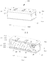
FIG. 1 is a perspective view of a phase-change water heater according to some embodiments of the present disclosure from an angle; -
FIG. 2 is a cross-sectional view taken along line A-A ofFIG. 1 ; -
FIG. 3 is a perspective view of a phase-change water heater according to some embodiments of the present disclosure from another angle; -
FIG. 4 is a cross-sectional view taken along line B-B ofFIG. 3 ; -
FIG. 5 is an exploded view of a phase-change water heater; -
FIG. 6 is a perspective view of a phase-change water heater according to some embodiments of the present disclosure from yet another angle; -
FIG. 7 is a cross-sectional view taken along line C-C ofFIG. 6 ; -
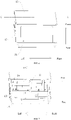
FIG. 8 is a schematic diagram illustrating connections of a water control system according to some embodiments of the present disclosure, in which arrows indicate water flow directions in a water discharging mode; -
FIG. 9 is a schematic diagram illustrating connections of a water control system according to some embodiments of the present disclosure, wherein arrows indicate water flow directions in a circulation heating mode; and -
FIG. 10 is a schematic diagram of a partial structure of a water control system according to some embodiments of the present disclosure. -
- phase-
change water heater 100; -
housing 10;chamber 11;panel assembly 12;glass plate 121; connectingplate 122;front housing 13; port 131; first connectingmember 132; frontmain plate 133;front side plate 134;rear housing 14; second connectingmember 141; rearmain plate 142;rear side plate 143;gap structure 15;reinforced structure 16;end plate 17;partition plate 18; -
inner container 20; -
water control system 40;water inlet pipe 41;water outlet pipe 42; one-way valve 43;thermostatic valve 44;heater 45;water pump 46;heat exchanger 47;water inlet 471;water outlet 472. - Embodiments of the present disclosure will be described in detail below, and examples of the embodiments are illustrated in the accompanying drawings, throughout which same or similar reference numerals refer to the same or similar elements or elements having the same or similar functions. The embodiments described below with reference to the accompanying drawings are illustrative and intended to explain the present disclosure and should not be construed as limiting the present disclosure.
- After in-depth research and bold attempts, the inventor has broken through disadvantages of existing electric water heaters, which are bulky and single in appearance. After years of arduous efforts, a brand-new phase-
change water heater 100 is designed. The phase-change water heater 100 makes full use of properties of a phase change material in storing heat at high temperature and releasing heat at low temperature, so as to meet needs of users who want to use water sooner. - Referring now to
FIGS. 1 to 10 , a phase-change water heater 100 according to embodiments of the present disclosure is described. The phase-change water heater 100 includes ahousing 10, aninner container 20, aheat exchanger 47, and awater control system 40. The phase-change water heater 100 at least has a water discharging mode and a circulation heating mode. - Specifically, as shown in
FIGS. 1 to 2 , thehousing 10 defines achamber 11, and theinner container 20 is disposed in thechamber 11. That is, thehousing 10 provides an installation space, and theinner container 20 is installed in thechamber 11. - The
inner container 20 has a phase-change material filled therein. The phase-change material has heat absorption and heat release functions. Theheat exchanger 47 is buried in the phase-change material. When there is a temperature difference between the phase-change material and the water in theheat exchanger 47, the phase-change material exchanges heat with theheat exchanger 47. That is, in the case that the water in theheat exchanger 47 has a lower temperature than the phase-change material, the heat of the phase-change material is released to the water in theheat exchanger 47, and the water temperature in theheat exchanger 47 rapidly rises; in the case that the water in theheat exchanger 47 has a higher temperature than the phase-change material, the phase-change material will absorb the heat of the water in theheat exchanger 47, and thus the temperature of the phase-change material will rise constantly. - The
water control system 40 is connected to awater inlet 471 and awater outlet 472 of theheat exchanger 47. The circulation heating mode and the water discharging mode are switchable by thewater control system 40. In the water discharging mode, theheat exchanger 47 supplies hot water to the outside, and thewater control system 40 supplements water to thewater inlet 471 of theheat exchanger 47, and in this process, the heat of the phase-change material can be constantly transferred to the water in theheat exchanger 47, thereby realizing constant supply of hot water to the outside. In the circulation heating mode, theheat exchanger 47 does not supply hot water to the outside, and water flows circularly between thewater control system 40 and theheat exchanger 47 after being heated in thewater control system 40, and in this process, the phase-change material constantly absorbs heat of the water in theheat exchanger 47 until the temperature of the phase-change material reaches a preset temperature. - That is, a water discharge capacity (i.e., a maximum water discharge amount) of the phase-
change water heater 100 is in positive correlation with the heat storage capacity of the phase-change material. The phase-change water heater 100 stores heat in the phase-change material in advance, and the phase-change material can release the heat quickly to water in theheat exchanger 47 when hot water is in need, so that the purpose of discharging the hot water sooner is achieved. - In addition, compared with the traditional water heater, since the water in the
heat exchanger 47 is constantly updated and replaced in the water discharging process of the phase-change water heater 100, the problem of use of residual water does not exist, the problem of bacteria growing in theheat exchanger 47 is avoided, and healthy water can be provided for users. - Compared with the traditional water heater, the phase-
change water heater 100 according to the embodiments of the present disclosure can realize sooner hot water discharge by using the heat storage capacity of the phase-change material without repeated heating, thereby saving energy consumption and avoiding the problems of dirt and pollution caused by long-term heating of theinner container 20. - In some embodiments of the present disclosure, with reference to
FIGS. 3 to 5 , thehousing 10 has apanel assembly 12 provided on a front surface thereof, that is, thepanel assembly 12 is disposed in front of thehousing 10 to cover a configuration of the surface of thehousing 10, an internal structure of the phase-change water heater 100 cannot be observed through a decoration of thepanel assembly 12, and therefore an entirety thereof is simple and elegant. - The
panel assembly 12 is disposed in front of thehousing 10, thepanel assembly 12 includes a connectingplate 122 and aglass plate 121, and theglass plate 121 is adhered to the connectingplate 122. By providing thepanel assembly 12 in the front of thehousing 10, thepanel assembly 12 may, on the one hand, reinforce a structural strength of a housing assembly and, on the other hand, may also shield the configuration of the surface of thehousing 10. According to the phase-change water heater 100 of the embodiments of the present disclosure, thepanel assembly 12 is disposed in front of thehousing 10, so that problems that the housing assembly of the phase-change water heater 100 has a complex structure and an assembling process thereof is complicated are solved. - Furthermore, a volume of the phase-change material expands as the temperature increases, and shrink as the temperature decreases, so that a volume of the
inner container 20 also changes accordingly. In particular, in the case that theglass plate 121 is provided on thehousing 10, theglass plate 121 is easily broken due to crushing. - The inventor has noted the above problems in the design process, and has made an innovative improvement to the structure of the
housing 10 of the phase-change water heater 100 in order to avoid the deformation of theinner container 20 pressing theglass plate 121. - Specifically, as shown in
FIGS. 6 and 7 , thehousing 10 includes afront housing 13 and arear housing 14 that are connected to each other, aglass plate 121 and a connectingplate 122 are provided in front of thefront housing 13, theglass plate 121 is disposed on the connectingplate 122, the connectingplate 122 is connected to thefront housing 13, and a rear surface of the connectingplate 122 and a front surface of thefront housing 13 have agap structure 15 provided therebetween. Thegap structure 15 may allow a partial gap to be present between thefront housing 13 and the connectingplate 122, i.e., allow thefront housing 13 and the connectingplate 122 to be partially separated. - In other words, the rear surface of the connecting
plate 122 and the front surface of thefront housing 13 are at least partially not in contact with each other, so that the force of the expansion of theinner container 20 acting on thefront housing 13 is not completely transferred to the connectingplate 122, thereby reducing an influence of the expansion of theinner container 20 on theglass plate 121 to some extent and avoiding a deformation of theglass plate 121 due to the expansion force. - The forming position of the
gap structure 15 is not particularly limited, and thegap structure 15 may be formed on the connectingplate 122, or thegap structure 15 may be formed on thefront housing 13, or thegap structure 15 may be formed on both the connectingplate 122 and thefront housing 13. Therefore, according to thehousing 10 assembly of the embodiment of the present disclosure, thegap structure 15 provided between the rear surface of the connectingplate 122 and the front surface of thefront housing 13 reduces the influence of the expansion force of theinner container 20 on theglass plate 121, ensures a flatness of theglass plate 121, and prevents deformation of theglass plate 121. - That is, the rear surface of the connecting
plate 122 is separated from the front surface of thefront housing 13 by a convex hull. The larger a protruding height of the convex hull with respect to the rear surface of the connectingplate 122, the larger the gap between the connectingplate 122 and thefront housing 13. - Further optionally, the convex hull is formed by concaving from a front side of the connecting
plate 122 to a rear side of the connectingplate 122. That is, the convex hull is formed by stretching from front to back, and the front surface of connectingplate 122 has a concave pit formed relative to a position where the convex hull is located. A screw hole can be formed on the convex hull, and under the condition that thefront housing 13 and the connectingplate 122 are locked by a screw, the screw can be hidden in the concave pit, thereby avoiding the screw squeezing theglass plate 121. - In some other embodiments of the present disclosure, as shown in
FIG. 1 in conjunction withFIG. 2 andFIG. 5 , thehousing 10 has theglass plate 121 disposed on the front surface thereof, theinner container 20 is disposed in thehousing 10, theinner container 20 has the phase-change material filled therein, theheat exchanger 47 is buried in the phase-change material, and thehousing 10 or theinner container 20 has a reinforcedstructure 16 provided thereon, the reinforcedstructure 16 being configured to resist expansion of the phase-change material towards theglass plate 121. - The reinforced
structure 16 is disposed on thehousing 10 and/or theinner container 20, for example, the reinforcedstructure 16 may be connected onto thehousing 10, the reinforcedstructure 16 may be connected onto theinner container 20, or the reinforcedstructure 16 may be connected respectively onto thehousing 10 and theinner container 20. - It can be understood that, since the
housing 10 has theglass plate 121 disposed on the front surface thereof according to the present disclosure, theglass plate 121 is brittle and is easily damaged. That is, the deformation of the phase-change material of theglass plate 121 has a greater influence on theglass plate 121. - In order to reduce the influence of the phase-change material on the
glass plate 121, the reinforcedstructure 16 is provided for resisting the force of the phase-change material towards theglass plate 121, so that the pressure applied to theglass plate 121 is reduced, the influence of the phase-change material on theglass plate 121 can be reduced, and deformation of theglass plate 121 is prevented. - The reinforced
structure 16 is disposed on an outer wall of theinner container 20 and at least a portion of the reinforcedstructure 16 is on the same side as theglass plate 121. At least a portion of the reinforcedstructure 16 is on the same side as theglass plate 121. In other words, at least a portion of the reinforcedstructure 16 is disposed on a side wall of theinner container 20 close to theglass plate 121. That is, a portion of the reinforcedstructure 16 may be on the same side as theglass plate 121, or the entire reinforcedstructure 16 may be on the same side as theglass plate 121. The reinforcedstructure 16 is disposed on the outer wall of theinner container 20, and plays a role of fastening theinner container 20, resisting the expansion force of the phase-change material towards theglass plate 121, and protecting theglass plate 121. - The above embodiments are merely illustrative and should not be construed as limiting the scope of the present disclosure. For example, the reinforced
structure 16 may be disposed on an inner wall of theinner container 20, and the reinforcedstructure 16 may alternatively be disposed on thehousing 10. In other words, the location of the reinforcedstructure 16 in the present disclosure is not exclusive as long as the reinforcedstructure 16 is capable of resisting the expansion force of the phase-change material towards theglass plate 121. - In some other embodiments of the present disclosure, specifically, as shown in
FIGS. 1 to 3 andFIG. 5 , thehousing 10 defines achamber 11, and at least one sidewall of thehousing 10 each has a port. The port is in communication with thechamber 11, and devices such as an instant heating assembly, an energy storage tank, an electric control board, and awater pump 46 are provided in thechamber 11. Maintenance personal can overhaul the above-mentioned devices through the port. Anend plate 17 may be formed on one side wall (left side wall or right side wall) of thehousing 10, or,end plates 17 are formed on both of the two side walls (left side wall and right side wall) of thehousing 10. - The
end plate 17 is detachably disposed on the side wall and is configured to close the port. That is, theend plate 17 detachably fits with thehousing 10, so that theend plate 17 can be detached from thehousing 10 when in need of maintenance. Under normal use conditions, theend plate 17 can be mounted on thehousing 10 to close thechamber 11, so as to ensure a tightness of thechamber 11. - Therefore, according to the phase-
change water heater 100 of the embodiment of the present disclosure, at least one side wall of thehousing 10 each has a port disposed thereon, and the port is detachably closed by theend plate 17, so that the maintenance of the devices in thechamber 11 is facilitated, and the tightness of thehousing 10 can be ensured. - In an optional embodiment, the
end plate 17 is connected to the side wall of thehousing 10 in a plug-in manner. That is, one of theend plate 17 and thehousing 10 has a buckle, the other one of theend plate 17 and thehousing 10 has a snapping groove, and theend plate 17 and thehousing 10 are connected through the cooperation of the buckle and the snapping groove. Theend plate 17 coordinates with thehousing 10 in the plug-in manner, which is convenient to assembling and disassembling, the processing process is simple, and the realization is easy. - Since the
end plate 17 is smaller and lighter in mass relative to thehousing 10, theend plate 17 can be more easily plugged into thehousing 10 by providing the buckle on theend plate 17. - In some other embodiments of the present disclosure, the
housing 10 includes: apanel assembly 12, afront housing 13, and arear housing 14 opened forward. - As shown in
FIGS. 2 and6 , thepanel assembly 12, thefront housing 13 and therear housing 14 are sequentially connected, thefront housing 13 is opened backwards, therear housing 14 is opened forward, thechamber 11 is defined by thefront housing 13 and therear housing 14, thefront housing 13 has a first connectingmember 132 disposed therein, therear housing 14 has a second connectingmember 141 disposed therein, the second connectingmember 141 coordinating with the first connectingmember 132, and as shown inFIG. 10 , thepanel assembly 12 is disposed on the front surface of thefront housing 13. - In other words, the first connecting
member 132 is disposed in the chamber formed by thefront housing 13, the second connectingmember 141 is disposed in the chamber formed by therear housing 14, and thefront housing 13 and therear housing 14 are connected by the first connectingmember 132 and the second connectingmember 141. That is, the first connectingmember 132 and the second connectingmember 141 are both disposed in thechamber 11 and are not exposed outside thehousing 10, so as to improve an overall simplicity of the appearance of thehousing 10. - In some embodiments, as shown in
FIG. 5 , thefront housing 13 includes a frontmain plate 133, and afront side plate 134 formed on a periphery of the frontmain plate 133 and extending backwards. The first connectingmember 132 is a tubular column, and the first connectingmember 132 is formed on thefront side plate 134 and extends in a front-rear direction. As shown inFIG. 6 , therear housing 14 include: a rearmain plate 142 and arear side plate 143 formed at a periphery of the rearmain plate 142 and extending forward. The second connectingmember 141 is a tubular column, and the second connectingmember 141 is formed on therear side plate 143 and extends in the front-rear direction. - The
front side plate 134 and therear side plate 143 may be connected to each other in a butt joint manner, at least a part of thefront side plate 134 may wrap an outer peripheral surface of therear side plate 143, or at least a part of therear side plate 143 may wrap the outer peripheral surface of thefront side plate 134. The first connectingmember 132 is connected to the frontmain plate 133 and extends in the front-rear direction, the second connectingmember 141 is connected to therear housing 14 and extends in the front-rear direction, and the first connectingmember 132 is adapted to be mating-connected to the second connectingmember 141. In other words, the frontmain plate 133 and therear housing 14 are connected by the first connectingmember 132 and the second connectingmember 141, and both the first connectingmember 132 and the second connectingmember 141 are configured as tubular columns. In this way, structural strength of the first connectingmember 132 and the second connectingmember 141 can be improved, that is, connection strength between the frontmain plate 133 and therear housing 14 can be improved. - In some optional embodiments, as shown in
FIG. 5 , the first connectingmember 132 has a first screw hole disposed thereon, the second connectingmember 141 has a second screw hole disposed thereon, and the first connectingmember 132 and the second connectingmember 141 are interlocked by a screw. Specifically, the first screw hole extends in an axial direction of the first connectingmember 132 and penetrates through the first connectingmember 132 and the frontmain plate 133, and the second screw hole extends in an axial direction of the second connectingmember 141 and penetrates through the frontmain plate 133, the first connectingmember 132, and the second connectingmember 141 so as to connect the first connectingmember 132 and the second connectingmember 141. Since thepanel assembly 12 is disposed on the front surface offront housing 13, an occurrence of corrosion failure of the screw due to exposure to the air can be effectively avoided, a service life of the screw can therefore be improved, a connection stability of the housing assembly can be guaranteed, and the maintenance can also be facilitated. - In some other embodiments of the present disclosure, the phase-
change water heater 100 at least includes a water discharging mode and a circulation heating mode. In the water discharging mode, cold water in awater inlet pipe 41 and hot water flowing out of theheat exchanger 47 flow together into athermostatic valve 44 to be mixed, and the cold water in thewater inlet pipe 41 is also synchronously delivered into theheat exchanger 47 to supplement the water amount. Aheater 45 may or may not preheat the cold water before the cold water enters theheat exchanger 47. In the circulation heating mode, thewater inlet pipe 41 and thewater outlet pipe 42 are both closed, water flows circularly between theheat exchanger 47 and theheater 45 under the pumping pressure of thewater pump 46, and before the cold water enters theheat exchanger 47, theheater 45 must preheat the cold water to ensure that the phase-change material can store heat sufficiently. A heating pipe can be an instant heat pipe, and a power of the instant heat pipe can be adjustable, so that the instant heat pipe can adopt different heating powers for heating in different operation modes. - However, on the premise that a space structure of the phase-
change water heater 100 is limited, it is uneasy to facilitate the installation of the pipeline and the structure of thewater control system 40 while ensuring excellent performance in the product development process, the present disclosure aims to solve the problems on complex pipeline, difficult assembling operation and performance stability of thewater control system 40 of the phase-change water heater 100. - Referring now to
FIGS. 7 to 9 , thewater control system 40 of the phase-change water heater 100 according to embodiments of the present disclosure includes: aheat exchanger 47, awater inlet pipe 41, and awater outlet pipe 42. - Specifically, the
heat exchanger 47 includes awater inlet 471 and awater outlet 472. Theheat exchanger 47 is buried in the phase-change material of the phase-change water heater 100, and when there is a temperature difference between the phase-change material and the water in theheat exchanger 47, the phase-change material exchanges heat with theheat exchanger 47. That is, in the case that the water in theheat exchanger 47 has a lower temperature than the phase-change material, the heat of the phase-change material is released to the water in theheat exchanger 47; in the case that the water in theheat exchanger 47 has a higher temperature than the phase-change material, the phase-change material absorbs heat from the water in theheat exchanger 47. - As shown in
FIG. 7 andFIG. 8 , an outlet of thewater inlet pipe 41 is connected respectively to thewater inlet 471 and thewater outlet 472 of theheat exchanger 47. It should be noted that, in the present disclosure, "connected" should be understood in a broad sense, and may represent a direct connection or an indirect connection. Here, since a one-way valve 43 and athermostatic valve 44 are disposed in parallel between thewater inlet pipe 41 and thewater outlet 472 of theheat exchanger 47, thewater inlet pipe 41 is connected indirectly to thewater outlet 472 of theheat exchanger 47. Further, since aheater 45 is disposed between thewater inlet pipe 41 and thewater inlet 471 of theheat exchanger 47, thewater inlet pipe 41 is also connected indirectly to thewater inlet 471 of theheat exchanger 47. - In the
water control system 40, when the phase-change water heater 100 is in the water discharging mode, water in thewater inlet pipe 41 can be simultaneously delivered to thethermostatic valve 44 and theheat exchanger 47, thereby realizing discharge of water from thewater outlet pipe 42, feeding of water into thewater inlet pipe 41, and a continuous water discharge from the phase-change water heater 100. - A
water pump 46 is disposed between thewater inlet 471 of theheat exchanger 47 and thewater outlet 472 of theheat exchanger 47. In the circulation heating mode, thewater pump 46 drives a water flow to flow between the inside and outside of theheat exchanger 47. It will be appreciated that in the water discharging mode, thewater pump 46 may not be activated, and thewater pump 46 may only act as a water flow channel. Thus, the energy consumption of the phase-change water heater 100 can be reduced, and the service life of thewater pump 46 can be extended. - As shown in
FIG. 9 , in the circulation heating mode, thewater inlet 471 and thewater outlet 472 of theheat exchanger 47 are communicated with each other through a pipeline where the one-way valve 43 is located. In other words, in the water discharging mode, the one-way valve 43 is subjected to hydraulic pressure to disconnect thewater inlet 471 of theheat exchanger 47 from thewater outlet 472 of theheat exchanger 47, so that cold water is prevented from reversely entering theheat exchanger 47 from a path where the one-way valve 43 is located, and normal flow of thewater control system 40 is ensured. - In short, according to the
water control system 40 of the phase-change water heater 100 in the embodiments of the present disclosure, the outlet of thewater inlet pipe 41 is respectively connected to thewater inlet 471 and thewater outlet 472 of theheat exchanger 47, and the one-way valve 43 and thethermostatic valve 44 are disposed in parallel between thewater inlet pipe 41 and thewater outlet 472 of theheat exchanger 47, which not only simplifies a pipeline layout of thewater control system 40, but also facilitates a switching between the circulation heating mode and the water discharging mode of thewater control system 40. - In an optional embodiment, the
water pump 46 is disposed between thewater inlet 471 of theheat exchanger 47 and the outlet of thewater inlet pipe 41. That is, thewater pump 46 is disposed close thewater inlet pipe 41, so that thewater pump 46 can be fully filled with cold water when the phase-change water heater 100 is not in an operating state (neither in the circulation heating mode nor in the water discharging mode), and thus, thewater pump 46 can be prevented from being soaked in hot water for a long time, thereby extending the service life of thewater pump 46. - In some other embodiments of the present disclosure, a heat insulation layer is disposed between the outer wall of the
inner container 20 and the inner wall of thehousing 10. The heat insulation layer can prevent the heat of theinner tank 20 from radiating to the outside, improve a heat insulation performance of the phase-change water heater 100, and reduce energy consumption. The heat insulation layer can be made of a foam material. - In an optional embodiment, the phase-change water heater further includes a
partition plate 18, thepartition plate 18 divides thechamber 11 into a first installation chamber and a second installation chamber that are independent from each other and are closed to each other, one of thewater control system 40 and theinner container 20 is disposed in the first installation chamber, and the other one of thewater control system 40 and theinner container 20 is disposed in the second installation chamber. Therefore, the thermal insulation material can be prevented from entering thewater control system 40 and the safety of the circuit is ensured. - In the present disclosure, unless expressly stated or limited otherwise, the recitation of a first feature "on" or "under" a second feature may include a case of the first and second features being in direct contact, and may also include a case that the first and second features are not in direct contact, but are in contact via another feature between them. Also, the first feature "on", "above", or "over" the second feature may include the first feature being right above and obliquely above the second feature, or simply indicate that the first feature is at a higher level than the second feature. The first feature being "under", "beneath", or "below" the second feature includes the first feature being right under and obliquely under the second feature, or simply mean that the first feature is at a lower level than the second feature.
- In the description of the specification, reference to the description of "one embodiment", "some embodiments", "an example", "a specific example", "some examples" or the like means that a particular feature, structure, material, or characteristic described in connection with the embodiment or example is included in at least one embodiment or example of the present disclosure. In this specification, the schematic representations of the above terms do not necessarily refer to the same embodiment or example. Furthermore, the particular features, structures, materials, or characteristics described may be combined in any suitable manner in any one or more embodiments or examples.
- Although embodiments of the present disclosure have been shown and described above, it will be understood that the above embodiments are exemplary and should not be construed as limiting the present disclosure, and those skilled in the art may make variations, modifications, substitutions and alterations to the above embodiments within the scope of the present disclosure without departing from the principles and ideas of the present disclosure.
Claims (10)
- A phase-change water heater, having at least a water discharging mode and a circulation heating mode, the phase-change water heater comprising:a housing defining a chamber;an inner container disposed in the chamber, and having a phase-change material filled therein;a heat exchanger buried in the phase-change material; anda water control system connected to a water inlet and a water outlet of the heat exchanger, wherein the circulation heating mode and the water discharging mode are switchable by the water control system.
- The phase-change water heater according to claim 1, wherein a front surface of the housing is provided with a panel assembly , wherein the panel assembly comprises a connecting plate and a glass plate, and the glass plate is adhered on the connecting plate.
- The phase-change water heater according to claim 1, wherein the housing comprises a front housing and a rear housing that are connected to each other, the chamber is defined by the front housing and the rear housing, a glass plate and a connecting plate are provided in front of the front housing, the glass plate is disposed on the connecting plate, and a gap structure is provided between the connecting plate and the front housing.
- The phase-change water heater according to claim 3, wherein the gap structure comprises one or more convex hulls, wherein the one or more convex hulls are formed on the connecting plate and protruding backwards.
- The phase-change water heater according to claim 1, a glass plate is provided on a front surface of the housing , and a reinforced structure is provided on the housing or the inner container to resist expansion of the phase-change material towards the glass plate.
- The phase-change water heater according to claim 5, wherein the reinforced structure is disposed on an outer wall of the inner container and at least a portion of the reinforced structure is on the same side as the glass plate.
- The phase-change water heater according to claim 1, wherein at least a side wall of the housing has a port, and the phase-change water heater further comprises an end plate that is detachably disposed on the side wall to close the port.
- The phase-change water heater according to claim 7, wherein the end plate is connected to the side wall of the housing in a plug-in manner.
- The phase-change water heater according to claim 1, wherein the water control system comprises:a water inlet pipe, an outlet of the water inlet pipe being respectively connected to the water inlet and the water outlet of the heat exchanger, wherein a one-way valve and a thermostatic valve are disposed in parallel between the water inlet pipe and the water outlet of the heat exchanger, and a heater is disposed between the water inlet pipe and the water inlet of the heat exchanger;a water outlet pipe connected to the thermostatic valve; anda water pump disposed between the water inlet of the heat exchanger and the water outlet of the heat exchanger, wherein in the circulation heating mode, the water inlet and the water outlet of the heat exchanger are communicated with each other through a pipeline where the one-way valve is located.
- The phase-change water heater according to claim 1, wherein the housing comprises a partition plate, the partition plate divides the chamber into a first installation chamber and a second installation chamber that are independent from each other and are not open to each other, either the water control system or the inner container is disposed in the first installation chamber, and the other of the water control system and the inner container is disposed in the second installation chamber.
Applications Claiming Priority (2)
| Application Number | Priority Date | Filing Date | Title |
|---|---|---|---|
| CN201910734892.0A CN112344557A (en) | 2019-08-09 | 2019-08-09 | Phase change water heater |
| PCT/CN2019/130626 WO2021027239A1 (en) | 2019-08-09 | 2019-12-31 | Phase-change water heater |
Publications (3)
| Publication Number | Publication Date |
|---|---|
| EP4012288A1 true EP4012288A1 (en) | 2022-06-15 |
| EP4012288A4 EP4012288A4 (en) | 2022-10-12 |
| EP4012288B1 EP4012288B1 (en) | 2024-12-25 |
Family
ID=74366869
Family Applications (1)
| Application Number | Title | Priority Date | Filing Date |
|---|---|---|---|
| EP19941552.2A Active EP4012288B1 (en) | 2019-08-09 | 2019-12-31 | Phase-change water heater |
Country Status (3)
| Country | Link |
|---|---|
| EP (1) | EP4012288B1 (en) |
| CN (1) | CN112344557A (en) |
| WO (1) | WO2021027239A1 (en) |
Families Citing this family (2)
| Publication number | Priority date | Publication date | Assignee | Title |
|---|---|---|---|---|
| US20240271824A1 (en) * | 2023-02-15 | 2024-08-15 | Phasestor Llc | Thermal retention apparatus for heating a liquid on demand |
| CN117224015B (en) * | 2023-09-14 | 2024-11-26 | 张家口众景健康科技有限公司 | Intelligent water dispenser pump |
Family Cites Families (13)
| Publication number | Priority date | Publication date | Assignee | Title |
|---|---|---|---|---|
| GB975946A (en) * | 1960-11-10 | 1964-11-25 | Baguley S Sons 1932 Ltd J | Improvements in or relating to water storage vessels in hot water supply systems |
| CN202709469U (en) * | 2012-08-01 | 2013-01-30 | 广东万和新电气股份有限公司 | Mounting structure for glass panel and surface shell of gas water heater |
| CN103363696A (en) * | 2013-06-25 | 2013-10-23 | 江苏启能新能源材料有限公司 | Frost heaving protecting structure for heat exchange tube of phase-change heat-storage solar water heater |
| FR3024214A3 (en) * | 2014-07-23 | 2016-01-29 | Muller & Cie Soc | SEASONAL THERMOELECTRIC STORAGE APPARATUS |
| CN204705041U (en) * | 2015-06-10 | 2015-10-14 | 北京宇田相变储能科技有限公司 | A kind of Instant heating type phase-change accumulation energy water heater |
| CN205014650U (en) * | 2015-09-11 | 2016-02-03 | 莱芜市凤凰太阳能有限公司 | Heat absorption of square inner bag and heat -retaining integral type water heater |
| CN205717913U (en) * | 2016-04-25 | 2016-11-23 | 芜湖美的厨卫电器制造有限公司 | Phase-change heat-storage water heater |
| CN105972839B (en) * | 2016-06-28 | 2018-01-19 | 常州戚墅堰机车车辆配件工业有限公司 | Hierarchical phase-change heat storage water tank |
| CN205939696U (en) * | 2016-07-28 | 2017-02-08 | 芜湖美的厨卫电器制造有限公司 | Phase -change thermal storage type water heater |
| CN206469331U (en) * | 2017-01-11 | 2017-09-05 | 吴雁军 | A kind of electric heater for improving panel mounting structure |
| CN207778784U (en) * | 2018-01-25 | 2018-08-28 | 芜湖美的厨卫电器制造有限公司 | Water heater |
| CN110081595A (en) * | 2018-01-25 | 2019-08-02 | 芜湖美的厨卫电器制造有限公司 | The small kitchen of heat accumulating type is precious |
| CN110081598A (en) * | 2018-01-25 | 2019-08-02 | 芜湖美的厨卫电器制造有限公司 | Heat from Low-temperature Flue Gas |
-
2019
- 2019-08-09 CN CN201910734892.0A patent/CN112344557A/en active Pending
- 2019-12-31 WO PCT/CN2019/130626 patent/WO2021027239A1/en not_active Ceased
- 2019-12-31 EP EP19941552.2A patent/EP4012288B1/en active Active
Also Published As
| Publication number | Publication date |
|---|---|
| EP4012288A4 (en) | 2022-10-12 |
| CN112344557A (en) | 2021-02-09 |
| EP4012288B1 (en) | 2024-12-25 |
| WO2021027239A1 (en) | 2021-02-18 |
Similar Documents
| Publication | Publication Date | Title |
|---|---|---|
| CN104456688B (en) | Central heating and cooling association system with energy storage tank | |
| EP4012288A1 (en) | Phase-change water heater | |
| CA2820293A1 (en) | Tap water device for storing and heating tap water | |
| CN113707909A (en) | Fuel cell emergency power generation system based on solid-state hydrogen storage technology | |
| US11493210B2 (en) | Instant hot water delivery system | |
| CN101569505B (en) | Hydraulic controlled electricity-saving multifunctional water dispenser | |
| KR20150097921A (en) | Water drain valve for prevention of freezing | |
| CN211316570U (en) | Phase change water heater | |
| CN101464060A (en) | Baffle plate type bearing water tank | |
| CN201110633Y (en) | Atmospheric pressure intelligent energy-saving drinking water machine | |
| CN221324713U (en) | Water heater based on phase change energy storage material | |
| CN211316542U (en) | Phase-change water heater | |
| CN2472135Y (en) | Volume various electric water heater | |
| CN106123309A (en) | Intake pre-heated electric heater | |
| CN206094528U (en) | Instant -heating water -storage type electric water heater | |
| CN204438524U (en) | Pressurized water tank and volumetric water heater | |
| CN216347050U (en) | Horizontal and vertical dual-purpose electric water heater | |
| KR101041276B1 (en) | Cool and warm purifier | |
| CN106766139A (en) | Double thermal source storage-type electric water heaters | |
| CN101251306A (en) | Vitrified enamel dual-inner container splitting solar energy-saving cistern | |
| CN111550921A (en) | A modular water heater | |
| CN218210097U (en) | Multi-energy hot water system | |
| CN222565471U (en) | Heating laminate for showcase | |
| CN113314730B (en) | Temperature control pipeline system of flow battery | |
| CN212870192U (en) | Dual-mode opening and closing integrated intelligent water tank |
Legal Events
| Date | Code | Title | Description |
|---|---|---|---|
| STAA | Information on the status of an ep patent application or granted ep patent |
Free format text: STATUS: THE INTERNATIONAL PUBLICATION HAS BEEN MADE |
|
| PUAI | Public reference made under article 153(3) epc to a published international application that has entered the european phase |
Free format text: ORIGINAL CODE: 0009012 |
|
| STAA | Information on the status of an ep patent application or granted ep patent |
Free format text: STATUS: REQUEST FOR EXAMINATION WAS MADE |
|
| 17P | Request for examination filed |
Effective date: 20220309 |
|
| AK | Designated contracting states |
Kind code of ref document: A1 Designated state(s): AL AT BE BG CH CY CZ DE DK EE ES FI FR GB GR HR HU IE IS IT LI LT LU LV MC MK MT NL NO PL PT RO RS SE SI SK SM TR |
|
| A4 | Supplementary search report drawn up and despatched |
Effective date: 20220912 |
|
| RIC1 | Information provided on ipc code assigned before grant |
Ipc: F24H 15/335 20220101ALI20220906BHEP Ipc: F24H 9/02 20060101ALI20220906BHEP Ipc: F28D 20/02 20060101ALI20220906BHEP Ipc: F24H 15/32 20220101ALI20220906BHEP Ipc: F24H 15/31 20220101ALI20220906BHEP Ipc: F24H 9/20 20220101ALI20220906BHEP Ipc: F24H 9/14 20060101ALI20220906BHEP Ipc: F24H 7/04 20060101AFI20220906BHEP |
|
| DAV | Request for validation of the european patent (deleted) | ||
| DAX | Request for extension of the european patent (deleted) | ||
| GRAP | Despatch of communication of intention to grant a patent |
Free format text: ORIGINAL CODE: EPIDOSNIGR1 |
|
| STAA | Information on the status of an ep patent application or granted ep patent |
Free format text: STATUS: GRANT OF PATENT IS INTENDED |
|
| RIC1 | Information provided on ipc code assigned before grant |
Ipc: F28D 21/00 20060101ALI20240701BHEP Ipc: F28D 1/03 20060101ALI20240701BHEP Ipc: F24H 9/14 20060101ALI20240701BHEP Ipc: F24H 9/20 20220101ALI20240701BHEP Ipc: F24H 15/31 20220101ALI20240701BHEP Ipc: F24H 15/32 20220101ALI20240701BHEP Ipc: F28D 20/02 20060101ALI20240701BHEP Ipc: F24H 9/02 20060101ALI20240701BHEP Ipc: F24H 15/335 20220101ALI20240701BHEP Ipc: F24H 7/04 20060101AFI20240701BHEP |
|
| INTG | Intention to grant announced |
Effective date: 20240805 |
|
| GRAS | Grant fee paid |
Free format text: ORIGINAL CODE: EPIDOSNIGR3 |
|
| GRAJ | Information related to disapproval of communication of intention to grant by the applicant or resumption of examination proceedings by the epo deleted |
Free format text: ORIGINAL CODE: EPIDOSDIGR1 |
|
| GRAL | Information related to payment of fee for publishing/printing deleted |
Free format text: ORIGINAL CODE: EPIDOSDIGR3 |
|
| STAA | Information on the status of an ep patent application or granted ep patent |
Free format text: STATUS: REQUEST FOR EXAMINATION WAS MADE |
|
| GRAP | Despatch of communication of intention to grant a patent |
Free format text: ORIGINAL CODE: EPIDOSNIGR1 |
|
| STAA | Information on the status of an ep patent application or granted ep patent |
Free format text: STATUS: GRANT OF PATENT IS INTENDED |
|
| INTC | Intention to grant announced (deleted) | ||
| GRAA | (expected) grant |
Free format text: ORIGINAL CODE: 0009210 |
|
| STAA | Information on the status of an ep patent application or granted ep patent |
Free format text: STATUS: THE PATENT HAS BEEN GRANTED |
|
| INTG | Intention to grant announced |
Effective date: 20241112 |
|
| AK | Designated contracting states |
Kind code of ref document: B1 Designated state(s): AL AT BE BG CH CY CZ DE DK EE ES FI FR GB GR HR HU IE IS IT LI LT LU LV MC MK MT NL NO PL PT RO RS SE SI SK SM TR |
|
| REG | Reference to a national code |
Ref country code: GB Ref legal event code: FG4D |
|
| REG | Reference to a national code |
Ref country code: CH Ref legal event code: EP |
|
| REG | Reference to a national code |
Ref country code: DE Ref legal event code: R096 Ref document number: 602019064120 Country of ref document: DE |
|
| REG | Reference to a national code |
Ref country code: IE Ref legal event code: FG4D |
|
| REG | Reference to a national code |
Ref country code: LT Ref legal event code: MG9D |
|
| PG25 | Lapsed in a contracting state [announced via postgrant information from national office to epo] |
Ref country code: HR Free format text: LAPSE BECAUSE OF FAILURE TO SUBMIT A TRANSLATION OF THE DESCRIPTION OR TO PAY THE FEE WITHIN THE PRESCRIBED TIME-LIMIT Effective date: 20241225 |
|
| PG25 | Lapsed in a contracting state [announced via postgrant information from national office to epo] |
Ref country code: FI Free format text: LAPSE BECAUSE OF FAILURE TO SUBMIT A TRANSLATION OF THE DESCRIPTION OR TO PAY THE FEE WITHIN THE PRESCRIBED TIME-LIMIT Effective date: 20241225 |
|
| PG25 | Lapsed in a contracting state [announced via postgrant information from national office to epo] |
Ref country code: BG Free format text: LAPSE BECAUSE OF FAILURE TO SUBMIT A TRANSLATION OF THE DESCRIPTION OR TO PAY THE FEE WITHIN THE PRESCRIBED TIME-LIMIT Effective date: 20241225 |
|
| PG25 | Lapsed in a contracting state [announced via postgrant information from national office to epo] |
Ref country code: NO Free format text: LAPSE BECAUSE OF FAILURE TO SUBMIT A TRANSLATION OF THE DESCRIPTION OR TO PAY THE FEE WITHIN THE PRESCRIBED TIME-LIMIT Effective date: 20250325 |
|
| PG25 | Lapsed in a contracting state [announced via postgrant information from national office to epo] |
Ref country code: LV Free format text: LAPSE BECAUSE OF FAILURE TO SUBMIT A TRANSLATION OF THE DESCRIPTION OR TO PAY THE FEE WITHIN THE PRESCRIBED TIME-LIMIT Effective date: 20241225 Ref country code: GR Free format text: LAPSE BECAUSE OF FAILURE TO SUBMIT A TRANSLATION OF THE DESCRIPTION OR TO PAY THE FEE WITHIN THE PRESCRIBED TIME-LIMIT Effective date: 20250326 |
|
| PG25 | Lapsed in a contracting state [announced via postgrant information from national office to epo] |
Ref country code: RS Free format text: LAPSE BECAUSE OF FAILURE TO SUBMIT A TRANSLATION OF THE DESCRIPTION OR TO PAY THE FEE WITHIN THE PRESCRIBED TIME-LIMIT Effective date: 20250325 |
|
| REG | Reference to a national code |
Ref country code: NL Ref legal event code: MP Effective date: 20241225 |
|
| PG25 | Lapsed in a contracting state [announced via postgrant information from national office to epo] |
Ref country code: NL Free format text: LAPSE BECAUSE OF FAILURE TO SUBMIT A TRANSLATION OF THE DESCRIPTION OR TO PAY THE FEE WITHIN THE PRESCRIBED TIME-LIMIT Effective date: 20241225 |
|
| REG | Reference to a national code |
Ref country code: AT Ref legal event code: MK05 Ref document number: 1754456 Country of ref document: AT Kind code of ref document: T Effective date: 20241225 |
|
| PG25 | Lapsed in a contracting state [announced via postgrant information from national office to epo] |
Ref country code: SM Free format text: LAPSE BECAUSE OF FAILURE TO SUBMIT A TRANSLATION OF THE DESCRIPTION OR TO PAY THE FEE WITHIN THE PRESCRIBED TIME-LIMIT Effective date: 20241225 |
|
| PG25 | Lapsed in a contracting state [announced via postgrant information from national office to epo] |
Ref country code: PL Free format text: LAPSE BECAUSE OF FAILURE TO SUBMIT A TRANSLATION OF THE DESCRIPTION OR TO PAY THE FEE WITHIN THE PRESCRIBED TIME-LIMIT Effective date: 20241225 |
|
| PG25 | Lapsed in a contracting state [announced via postgrant information from national office to epo] |
Ref country code: ES Free format text: LAPSE BECAUSE OF FAILURE TO SUBMIT A TRANSLATION OF THE DESCRIPTION OR TO PAY THE FEE WITHIN THE PRESCRIBED TIME-LIMIT Effective date: 20241225 |
|
| PG25 | Lapsed in a contracting state [announced via postgrant information from national office to epo] |
Ref country code: IS Free format text: LAPSE BECAUSE OF FAILURE TO SUBMIT A TRANSLATION OF THE DESCRIPTION OR TO PAY THE FEE WITHIN THE PRESCRIBED TIME-LIMIT Effective date: 20250425 |
|
| PG25 | Lapsed in a contracting state [announced via postgrant information from national office to epo] |
Ref country code: PT Free format text: LAPSE BECAUSE OF FAILURE TO SUBMIT A TRANSLATION OF THE DESCRIPTION OR TO PAY THE FEE WITHIN THE PRESCRIBED TIME-LIMIT Effective date: 20250428 |
|
| PG25 | Lapsed in a contracting state [announced via postgrant information from national office to epo] |
Ref country code: EE Free format text: LAPSE BECAUSE OF FAILURE TO SUBMIT A TRANSLATION OF THE DESCRIPTION OR TO PAY THE FEE WITHIN THE PRESCRIBED TIME-LIMIT Effective date: 20241225 |
|
| PG25 | Lapsed in a contracting state [announced via postgrant information from national office to epo] |
Ref country code: AT Free format text: LAPSE BECAUSE OF FAILURE TO SUBMIT A TRANSLATION OF THE DESCRIPTION OR TO PAY THE FEE WITHIN THE PRESCRIBED TIME-LIMIT Effective date: 20241225 Ref country code: RO Free format text: LAPSE BECAUSE OF FAILURE TO SUBMIT A TRANSLATION OF THE DESCRIPTION OR TO PAY THE FEE WITHIN THE PRESCRIBED TIME-LIMIT Effective date: 20241225 |
|
| PG25 | Lapsed in a contracting state [announced via postgrant information from national office to epo] |
Ref country code: SK Free format text: LAPSE BECAUSE OF FAILURE TO SUBMIT A TRANSLATION OF THE DESCRIPTION OR TO PAY THE FEE WITHIN THE PRESCRIBED TIME-LIMIT Effective date: 20241225 |
|
| PG25 | Lapsed in a contracting state [announced via postgrant information from national office to epo] |
Ref country code: CZ Free format text: LAPSE BECAUSE OF FAILURE TO SUBMIT A TRANSLATION OF THE DESCRIPTION OR TO PAY THE FEE WITHIN THE PRESCRIBED TIME-LIMIT Effective date: 20241225 |
|
| PG25 | Lapsed in a contracting state [announced via postgrant information from national office to epo] |
Ref country code: IT Free format text: LAPSE BECAUSE OF FAILURE TO SUBMIT A TRANSLATION OF THE DESCRIPTION OR TO PAY THE FEE WITHIN THE PRESCRIBED TIME-LIMIT Effective date: 20241225 |
|
| REG | Reference to a national code |
Ref country code: CH Ref legal event code: PL |
|
| PG25 | Lapsed in a contracting state [announced via postgrant information from national office to epo] |
Ref country code: LU Free format text: LAPSE BECAUSE OF NON-PAYMENT OF DUE FEES Effective date: 20241231 |
|
| PG25 | Lapsed in a contracting state [announced via postgrant information from national office to epo] |
Ref country code: SE Free format text: LAPSE BECAUSE OF FAILURE TO SUBMIT A TRANSLATION OF THE DESCRIPTION OR TO PAY THE FEE WITHIN THE PRESCRIBED TIME-LIMIT Effective date: 20241225 |
|
| PG25 | Lapsed in a contracting state [announced via postgrant information from national office to epo] |
Ref country code: MC Free format text: LAPSE BECAUSE OF FAILURE TO SUBMIT A TRANSLATION OF THE DESCRIPTION OR TO PAY THE FEE WITHIN THE PRESCRIBED TIME-LIMIT Effective date: 20241225 |
|
| REG | Reference to a national code |
Ref country code: DE Ref legal event code: R097 Ref document number: 602019064120 Country of ref document: DE |
|
| REG | Reference to a national code |
Ref country code: BE Ref legal event code: MM Effective date: 20241231 |
|
| PG25 | Lapsed in a contracting state [announced via postgrant information from national office to epo] |
Ref country code: DK Free format text: LAPSE BECAUSE OF FAILURE TO SUBMIT A TRANSLATION OF THE DESCRIPTION OR TO PAY THE FEE WITHIN THE PRESCRIBED TIME-LIMIT Effective date: 20241225 |
|
| PG25 | Lapsed in a contracting state [announced via postgrant information from national office to epo] |
Ref country code: BE Free format text: LAPSE BECAUSE OF NON-PAYMENT OF DUE FEES Effective date: 20241231 |
|
| PG25 | Lapsed in a contracting state [announced via postgrant information from national office to epo] |
Ref country code: CH Free format text: LAPSE BECAUSE OF NON-PAYMENT OF DUE FEES Effective date: 20241231 |
|
| PG25 | Lapsed in a contracting state [announced via postgrant information from national office to epo] |
Ref country code: IE Free format text: LAPSE BECAUSE OF NON-PAYMENT OF DUE FEES Effective date: 20241231 |
|
| PLBE | No opposition filed within time limit |
Free format text: ORIGINAL CODE: 0009261 |
|
| STAA | Information on the status of an ep patent application or granted ep patent |
Free format text: STATUS: NO OPPOSITION FILED WITHIN TIME LIMIT |
|
| 26N | No opposition filed |
Effective date: 20250926 |
|
| PGFP | Annual fee paid to national office [announced via postgrant information from national office to epo] |
Ref country code: DE Payment date: 20251212 Year of fee payment: 7 |
|
| PGFP | Annual fee paid to national office [announced via postgrant information from national office to epo] |
Ref country code: GB Payment date: 20251211 Year of fee payment: 7 |
|
| PGFP | Annual fee paid to national office [announced via postgrant information from national office to epo] |
Ref country code: FR Payment date: 20251212 Year of fee payment: 7 |