EP4012104B1 - Vorgefertigtes wasserkontrollsystem - Google Patents
Vorgefertigtes wasserkontrollsystem Download PDFInfo
- Publication number
- EP4012104B1 EP4012104B1 EP21213691.5A EP21213691A EP4012104B1 EP 4012104 B1 EP4012104 B1 EP 4012104B1 EP 21213691 A EP21213691 A EP 21213691A EP 4012104 B1 EP4012104 B1 EP 4012104B1
- Authority
- EP
- European Patent Office
- Prior art keywords
- prefabricated
- wall component
- control system
- water control
- gate
- Prior art date
- Legal status (The legal status is an assumption and is not a legal conclusion. Google has not performed a legal analysis and makes no representation as to the accuracy of the status listed.)
- Active
Links
Images






Classifications
-
- E—FIXED CONSTRUCTIONS
- E02—HYDRAULIC ENGINEERING; FOUNDATIONS; SOIL SHIFTING
- E02B—HYDRAULIC ENGINEERING
- E02B3/00—Engineering works in connection with control or use of streams, rivers, coasts, or other marine sites; Sealings or joints for engineering works in general
- E02B3/04—Structures or apparatus for, or methods of, protecting banks, coasts, or harbours
- E02B3/10—Dams; Dykes; Sluice ways or other structures for dykes, dams, or the like
-
- E—FIXED CONSTRUCTIONS
- E02—HYDRAULIC ENGINEERING; FOUNDATIONS; SOIL SHIFTING
- E02B—HYDRAULIC ENGINEERING
- E02B3/00—Engineering works in connection with control or use of streams, rivers, coasts, or other marine sites; Sealings or joints for engineering works in general
- E02B3/04—Structures or apparatus for, or methods of, protecting banks, coasts, or harbours
- E02B3/10—Dams; Dykes; Sluice ways or other structures for dykes, dams, or the like
- E02B3/102—Permanently installed raisable dykes
-
- E—FIXED CONSTRUCTIONS
- E02—HYDRAULIC ENGINEERING; FOUNDATIONS; SOIL SHIFTING
- E02B—HYDRAULIC ENGINEERING
- E02B5/00—Artificial water canals, e.g. irrigation canals
- E02B5/08—Details, e.g. gates, screens
-
- E—FIXED CONSTRUCTIONS
- E02—HYDRAULIC ENGINEERING; FOUNDATIONS; SOIL SHIFTING
- E02B—HYDRAULIC ENGINEERING
- E02B7/00—Barrages or weirs; Layout, construction, methods of, or devices for, making same
- E02B7/02—Fixed barrages
- E02B7/04—Dams across valleys
-
- E—FIXED CONSTRUCTIONS
- E02—HYDRAULIC ENGINEERING; FOUNDATIONS; SOIL SHIFTING
- E02B—HYDRAULIC ENGINEERING
- E02B7/00—Barrages or weirs; Layout, construction, methods of, or devices for, making same
- E02B7/20—Movable barrages; Lock or dry-dock gates
Definitions
- the present invention relates to prefabricated water control systems.
- Sluice gates are used selectively to control water flow from one area of a channel to another by opening or closing off the channel to the water flow.
- the frame/foundation of the sluice gate is cast directly at the application site of the sluice gate.
- the construction time is long, as the cement needs to settle and harden before a gate member can be installed therein.
- the hardening of the cement may be affected by the weather conditions, resulting in a frame/foundation of poor quality and strength.
- sedimentation prevents the functioning of the sluice gate.
- a specific problem with such water control systems is that they are difficult to service and time-consuming to replace.
- EP3199706 discloses a pre-fabricated water control sluice gate system comprising a first frame, a lifting anchor or coupler adapted for receiving a lifting anchor, one or more sluice gate members, and an actuator adapted for moving the sluice gate members.
- One aspect relates to prefabricated water control system comprising:
- the prefabricated water control system further comprises a sheet pile wall or a base plate adapted for supporting said bottom section of said wall component.
- the relatively simple side view shape (I, L, or T) of the prefabricated element combined with the support units allows for a prefabricated water control system that is easy to mount, service, and replace.
- the wall component should be vertical, but it is contemplated within the scope of the invention that the wall element could also be offset with -20 to 20 degrees from vertical, and maybe more.
- the prefabricated element is a pre-cast reinforced concrete element.
- pre-cast as used throughout this application means the opposite of cast in situ.
- the pre-cast reinforced concrete element is finished as finished structures when shipped to a builder or customer, rather than being poured into temporary forms at the building site or place of use.
- reinforced concrete refers to concrete into which reinforcement bars or fibres have been cast to carry tensile loads in order to strengthen a structure that would otherwise be brittle.
- the prefabricated element may also be made of metal, wood, or a castable material.
- any suitable castable material such as cement, mortar, concrete, ceramics, thermoset plastics, and thermoplastics can be used for producing the prefabricated element.
- lifting anchor should be broadly construed to encompass any such device for lifting the frame with or without gate members and actuators installed therein.
- a coupler adapted for receiving a lifting anchor is embedded in the frame.
- the coupler may comprise internal or external threading, depending on the configuration of the lifting anchor.
- the lifting anchor or coupler adapted for receiving a lifting anchor is mechanically tied into the reinforcing members embedded in the castable material, such as concrete.
- the support units each comprises a first flange adapted for supporting a part of said front side or back side of said wall component.
- at least one of said support units comprises a first flange adapted for supporting a part of said front side of said wall component
- at least the other support unit comprises a second flange adapted for supporting a part of said back side of said wall component.
- the bottom section of the wall component comprises one or more channels, and one or more flaps or valves adapted for closing and opening said one or more channels collectively and/or individually.
- the channels use the water pressure difference across the wall component to flush water through the channels, thereby removing sediments that would otherwise block the functioning of the gate members.
- the bottom section of said wall component comprises a plurality of channels, and one or more flaps adapted for closing and opening said plurality of channels collectively and/or individually; and wherein said flaps are arranged on a single rotating and/or sliding shaft.
- the prefabricated element has a shape in a side view perspective substantially corresponding to an L-form, or an inverted T-form shaped by said wall component and a base plate (i.e., these two components combine to form the shape), and wherein said base plate comprises air and/or water channels adapted to be connected to a source of compressed air and/or water. Water and/or compressed air may thereby be used to remove sediments blocking the function of the one or more gate members.
- the prefabricated element has a shape in a side view perspective substantially corresponding to an L-form, or an inverted T-form shaped by said wall component and a base plate, and wherein said base plate comprises one or more suction channels adapted to be connected to a source of suction. With or without the function of the air/water channels, the suction channels may be used to remove sediments blocking the function of the one or more gate members.
- Another aspect relates to a method for segregating a body of water into two distinct parts with a prefabricated water control system according to the present invention.
- Another aspect relates to a method for segregating a body of water into two distinct parts with a prefabricated water control system comprising the steps of:
- prefabricated water systems 100A, 100B The following description is to be seen as non-limiting examples of prefabricated water systems 100A, 100B according to various embodiments of the present invention.
- the prefabricated water system 100A to the left shows a prefabricated water control system with a double gate 150 in accordance with various embodiments of the invention.
- the prefabricated water system 100B to the right shows a prefabricated water control system with a turn gate 120 in accordance with various embodiments of the invention.
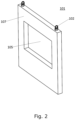
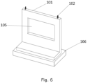
- the prefabricated water control system 100 as seen from a side view perspective comprises an I-, L-, or inverted T-shaped prefabricated element 101, one or more gate members 120, 140, 150 ( Figures 1 , and 8-11 ), two support units 103 ( Figures 1 , and 5 ), and optionally, but preferably, a sheet pile wall 104 ( Figures 1 , 5 , and 7 ), or a base plate 106 ( Figure 6 ).
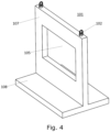
- the prefabricated element comprises a substantially vertical wall component 107 ( Figure 2 ), and, if L- og inverted T-shaped, also a base plate 108 (best seen in Figures 3 and 4 ).
- the base plate 108 may be configured with a hole or recess 109 as exemplified in Figure 3 with an optional part 109 at each side that can be omitted, thereby resulting in the formation of a recess 109.
- the hole or recess 109 is adapted for receiving one of said support units 103.
- Figure 5 shows a prefabricated water control system 100 where each support unit 103 comprises a first flange 110 adapted for supporting a part of the front side or back side of said wall component 107, and a second flange 111 adapted for supporting a part of the back side of said wall component 107.
- a suitable and general example of a support unit could be an H-beam, I-beam, angle beam, T-beam, or the like, preferably made of steel, preferably stainless.
- a support unit could be an H-beam, I-beam, angle beam, T-beam, or the like, preferably made of steel, preferably stainless.
- beams with flanges suitable for supporting a part of the back and/or front side of said wall component may be used, preferably made of steel, preferably stainless.
- FIG. 1 A specific example of a turn gate 120 may be seen in Figures 1 and 8.
- Figure 8 shows a prefabricated turn gate 120 mounted in a prefabricated frame 121 and mounted in two bearings 130.
- the turn gate 120 also comprises a prefabricated mounting 122 adapted for fastening to the wall component 107 and for supporting the frame 121.
- Figure 9 shows a prefabricated gate member in the form of a tilt gate 131 and comprising two bearings 130 for mounting the tilt gate 131 on the wall component 107.
- the tilt gate 131 can be mounted on all four sides of the opening 105, such that it either close from the side, the top, or the bottom.
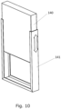
- Figure 10 shows a prefabricated gate member in the form of a sliding gate 140.
- the sliding gate 140 is mounted in a frame 141 adapted for mounting in the opening 105, or alternatively, in front of, or behind the opening 105.
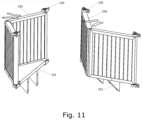
- Figure 11 shows a prefabricated gate member 150 in the form of a double port gate 150.
- a prefabricated mounting 151 is used for mounting the double port gate 150 to the wall component as well as for defining a bottom in said double port gate 150.
- Each gate is mounted in bearings 130 for opening and closing the gates.
- Figure 12 shows a prefabricated element having an inverted T-shape in accordance with various embodiments of the invention, and where the base part of the wall component 107 comprises five (i.e., multiple) channels, and a single flap adapted for closing and opening the channels collectively. Such channels and flap may obviously also be included in the other examples.
Landscapes
- Engineering & Computer Science (AREA)
- General Engineering & Computer Science (AREA)
- Structural Engineering (AREA)
- Mechanical Engineering (AREA)
- Civil Engineering (AREA)
- Environmental & Geological Engineering (AREA)
- Ocean & Marine Engineering (AREA)
- Barrages (AREA)
Claims (11)
- Vorgefertigtes Wasserkontrollsystem (100), das Folgendes umfasst:a. ein vorgefertigtes Element (101);b. ein oder mehrere Torelemente (120, 131, 140, 150); undc. zwei Stützeinheiten (103), die jeweils zum gleitenden Stützen des vorgefertigten Elements (101) geeignet sind;dadurch gekennzeichnet, dass das vorgefertigte Element (101) in einer Seitenansichtsperspektive eine Form aufweist, die im Wesentlichen einer I-Form, einer L-Form oder einer umgekehrten T-Form entspricht, und eine im Wesentlichen vertikale Wandkomponente (107) mit einer Vorderseite, einer Rückseite, einem unteren Abschnitt und zwei Seitenflächen aufweist, wobei das vorgefertigte Element (101) ferner Folgendes umfasst:i. eine erste Öffnung (105) in der Wandkomponente (107), die sich von der Vorderseite zu der Rückseite erstreckt; undii. mindestens einen Hubanker (102) oder einen Koppler, der zum Aufnehmen eines Hubankers geeignet ist;wobei das eine oder die mehreren Torelemente (120, 131, 140, 150) geeignet sind, die Größe der ersten Öffnung (105) in der Wandkomponente (107) zu regulieren, wodurch der Wasserstrom durch diese reguliert wird;wobei die zwei Stützeinheiten (103) jeweils zum gleitenden Stützen einer der Seitenflächen der Wandkomponente (107) und zum Einbauen in das Ufer eines Wasserkanals, in dem das Wasserkontrollsystem (100) positioniert ist, geeignet sind.
- Vorgefertigtes Wasserkontrollsystem (100) nach Anspruch 1, ferner umfassend eine Grundplatte (106), die zum Stützen des unteren Abschnitts der Wandkomponente (107) geeignet ist, wobei die Grundplatte (106) an jeder Seite mit einem Loch oder einer Aussparung konfiguriert ist, wobei das Loch oder die Aussparung zum Aufnehmen einer der Stützeinheiten (103) geeignet ist.
- Vorgefertigtes Wasserkontrollsystem (100) nach Anspruch 1, ferner umfassend eine Spundwand (104), die zum Stützen des unteren Abschnitts der Wandkomponente (107) geeignet ist.
- Vorgefertigtes Wasserkontrollsystem (100) nach einem der Ansprüche 1-3, wobei die Stützeinheiten (103) jeweils einen ersten Flansch (110) und optional einen zweiten Flansch (111) umfassen, die zum Stützen eines Teils der Vorderseite oder der Rückseite der Wandkomponente (107) geeignet sind.
- Vorgefertigtes Wasserkontrollsystem (100) nach einem der Ansprüche 1-3, wobei mindestens eine der Stützeinheiten (103) einen ersten Flansch (110) umfasst, der zum Stützen eines Teils der Vorderseite der Wandkomponente (107) geeignet sind, und wobei mindestens die andere Stützeinheit (103) einen zweiten Flansch (111) umfasst, der zum Stützen eines Teils der Rückseite der Wandkomponente (107) geeignet ist.
- Vorgefertigtes Wasserkontrollsystem (100) nach einem der Ansprüche 1-5, wobei das/die Torelement(e) (120, 131, 140, 150) aus einem Drehtor (120), einem Kipptor (131), einem Hebetor (140), einem Doppeltor (150) oder dergleichen ausgewählt ist/sind.
- Vorgefertigtes Wasserkontrollsystem (100) nach einem der Ansprüche 1-6, wobei der untere Abschnitt der Wandkomponente (107) einen oder mehrere Kanäle (160) und eine oder mehrere Klappen (107) oder Ventile umfasst, die zum gemeinsamen und/oder einzelnen Schließen und Öffnen des einen oder der mehreren Kanäle (160) geeignet sind.
- Vorgefertigtes Wasserkontrollsystem (100) nach einem der Ansprüche 1-6, wobei der untere Abschnitt der Wandkomponente eine Vielzahl von Kanälen (160) und eine oder mehrere Klappen (170) umfasst, die zum gemeinsamen und/oder einzelnen Schließen und Öffnen der Vielzahl von Kanälen (160) geeignet sind; und wobei die Klappen (170) auf einer einzelnen drehenden und/oder gleitenden Welle angeordnet sind.
- Vorgefertigtes Wasserkontrollsystem (100) nach einem der Ansprüche 1-8, wobei das vorgefertigte Element (101) in einer Seitenansichtsperspektive eine Form aufweist, die im Wesentlichen einer L-Form oder einer umgekehrten T-Form entspricht, die durch die Wandkomponente (107) und eine Grundplatte (108) geformt ist, und wobei die Grundplatte (108) Luft- und/oder Wasserkanäle umfasst, die geeignet sind, mit einer Druckluft- und/oder Wasserquelle verbunden zu sein.
- Vorgefertigtes Wasserkontrollsystem (100) nach einem der Ansprüche 1-9, wobei das vorgefertigte Element (101) in einer Seitenansichtsperspektive eine Form aufweist, die im Wesentlichen einer L-Form oder einer umgekehrten T-Form entspricht, die durch die Wandkomponente (107) und eine Grundplatte (108) geformt ist, und wobei die Grundplatte (108) einen oder mehrere Ansaugkanäle umfasst, die geeignet sind, mit einer Absaugquelle verbunden zu sein.
- Vorgefertigtes Wasserkontrollsystem (100) nach einem der Ansprüche 1-9, wobei das vorgefertigte Element (101) in einer Seitenansichtsperspektive eine Form aufweist, die im Wesentlichen einer L-Form oder einer umgekehrten T-Form entspricht, die durch die Wandkomponente (107) und eine Grundplatte (108) geformt ist, und wobei die Grundplatte (108) an jeder Seite mit einem Loch oder einer Aussparung (109) konfiguriert ist, wobei das Loch oder die Aussparung zum Aufnehmen einer der Stützeinheiten (103) geeignet ist.
Applications Claiming Priority (1)
| Application Number | Priority Date | Filing Date | Title |
|---|---|---|---|
| DKPA202001395A DK180625B1 (en) | 2020-12-14 | 2020-12-14 | Prefabricated water control system |
Publications (3)
| Publication Number | Publication Date |
|---|---|
| EP4012104A1 EP4012104A1 (de) | 2022-06-15 |
| EP4012104C0 EP4012104C0 (de) | 2025-07-09 |
| EP4012104B1 true EP4012104B1 (de) | 2025-07-09 |
Family
ID=78371699
Family Applications (1)
| Application Number | Title | Priority Date | Filing Date |
|---|---|---|---|
| EP21213691.5A Active EP4012104B1 (de) | 2020-12-14 | 2021-12-10 | Vorgefertigtes wasserkontrollsystem |
Country Status (2)
| Country | Link |
|---|---|
| EP (1) | EP4012104B1 (de) |
| DK (1) | DK180625B1 (de) |
Family Cites Families (3)
| Publication number | Priority date | Publication date | Assignee | Title |
|---|---|---|---|---|
| CA1325727C (en) * | 1988-06-03 | 1994-01-04 | Rene Fontaine | Door seal for water slide gates |
| US9537183B2 (en) * | 2014-06-16 | 2017-01-03 | Custom Water Management Solutions, Llc | Automatic water control system for open ditch drainage |
| EP3199706B1 (de) | 2016-01-28 | 2020-04-01 | Wintec Holding ApS | Vorgefertigtes schleusentorsystem zur wasserkontrolle |
-
2020
- 2020-12-14 DK DKPA202001395A patent/DK180625B1/en active IP Right Grant
-
2021
- 2021-12-10 EP EP21213691.5A patent/EP4012104B1/de active Active
Also Published As
| Publication number | Publication date |
|---|---|
| DK202001395A1 (en) | 2021-11-01 |
| EP4012104C0 (de) | 2025-07-09 |
| EP4012104A1 (de) | 2022-06-15 |
| DK180625B1 (en) | 2021-11-01 |
Similar Documents
| Publication | Publication Date | Title |
|---|---|---|
| US20140223851A1 (en) | Prefabricated reinforced concrete wall panel and installation method | |
| US11059201B2 (en) | Pre-stressed box culvert and methods for assembly thereof | |
| CN1751157A (zh) | 预应力脚手架系统 | |
| KR20090090055A (ko) | 무교대, 무받침 및 무신축이음의 일체식 복합슬래브교량 및이의 시공방법 | |
| CN108331385A (zh) | 一种检查坑预制柱结构及其施工方法 | |
| EP3336260A1 (de) | Methode zum bauen eines turmfundaments | |
| EP4012104B1 (de) | Vorgefertigtes wasserkontrollsystem | |
| EA009928B1 (ru) | Способ сооружения ленточного фундамента с продольной канавкой, элемент фундамента и приспособление для его фиксации и выравнивания, предназначенные для осуществления способа | |
| EP1402119B1 (de) | Fundament in wasser | |
| EP3199706B1 (de) | Vorgefertigtes schleusentorsystem zur wasserkontrolle | |
| EP3228753B1 (de) | Modulares vorgefertigtes wassersteuerungspumpensystem | |
| DK202100081U3 (da) | Vandstyringssystem | |
| CN111794543A (zh) | 基础托换体系及其施工方法 | |
| KR100975539B1 (ko) | 부등지간장을 가지는 스틸박스 연속교 및 이의 시공방법 | |
| EP3486376B1 (de) | Vorgefertigtes wasserregelndes schleusensystem mit sedimentationsschutzfunktion | |
| KR100709304B1 (ko) | 합성말뚝과 강널말뚝을 이용한 토목구조물 및 그의시공방법 | |
| WO1996000338A1 (en) | Prefabricated masonry fencing system | |
| JP2802612B2 (ja) | 水中型枠工法 | |
| EP4352309B1 (de) | Fundamentstruktur für konstruktionen | |
| CN222456120U (zh) | 一种深基坑围护立体支撑系统 | |
| CN214301693U (zh) | 桩挡墙加固结构 | |
| US20030084630A1 (en) | Perimeter walls | |
| GB2617894A (en) | A foundation beam | |
| AU684643B2 (en) | Prefabricated masonry fencing system | |
| CN121228750A (zh) | 钢套箱混凝土灌芯增大截面加固桥梁基础及施工方法 |
Legal Events
| Date | Code | Title | Description |
|---|---|---|---|
| PUAI | Public reference made under article 153(3) epc to a published international application that has entered the european phase |
Free format text: ORIGINAL CODE: 0009012 |
|
| STAA | Information on the status of an ep patent application or granted ep patent |
Free format text: STATUS: THE APPLICATION HAS BEEN PUBLISHED |
|
| AK | Designated contracting states |
Kind code of ref document: A1 Designated state(s): AL AT BE BG CH CY CZ DE DK EE ES FI FR GB GR HR HU IE IS IT LI LT LU LV MC MK MT NL NO PL PT RO RS SE SI SK SM TR |
|
| STAA | Information on the status of an ep patent application or granted ep patent |
Free format text: STATUS: REQUEST FOR EXAMINATION WAS MADE |
|
| 17P | Request for examination filed |
Effective date: 20221215 |
|
| RBV | Designated contracting states (corrected) |
Designated state(s): AL AT BE BG CH CY CZ DE DK EE ES FI FR GB GR HR HU IE IS IT LI LT LU LV MC MK MT NL NO PL PT RO RS SE SI SK SM TR |
|
| GRAP | Despatch of communication of intention to grant a patent |
Free format text: ORIGINAL CODE: EPIDOSNIGR1 |
|
| STAA | Information on the status of an ep patent application or granted ep patent |
Free format text: STATUS: GRANT OF PATENT IS INTENDED |
|
| INTG | Intention to grant announced |
Effective date: 20250218 |
|
| GRAS | Grant fee paid |
Free format text: ORIGINAL CODE: EPIDOSNIGR3 |
|
| GRAA | (expected) grant |
Free format text: ORIGINAL CODE: 0009210 |
|
| STAA | Information on the status of an ep patent application or granted ep patent |
Free format text: STATUS: THE PATENT HAS BEEN GRANTED |
|
| AK | Designated contracting states |
Kind code of ref document: B1 Designated state(s): AL AT BE BG CH CY CZ DE DK EE ES FI FR GB GR HR HU IE IS IT LI LT LU LV MC MK MT NL NO PL PT RO RS SE SI SK SM TR |
|
| REG | Reference to a national code |
Ref country code: GB Ref legal event code: FG4D |
|
| REG | Reference to a national code |
Ref country code: CH Ref legal event code: EP |
|
| REG | Reference to a national code |
Ref country code: IE Ref legal event code: FG4D |
|
| REG | Reference to a national code |
Ref country code: DE Ref legal event code: R096 Ref document number: 602021033717 Country of ref document: DE |
|
| U01 | Request for unitary effect filed |
Effective date: 20250728 |
|
| U07 | Unitary effect registered |
Designated state(s): AT BE BG DE DK EE FI FR IT LT LU LV MT NL PT RO SE SI Effective date: 20250801 |
|
| PG25 | Lapsed in a contracting state [announced via postgrant information from national office to epo] |
Ref country code: IS Free format text: LAPSE BECAUSE OF FAILURE TO SUBMIT A TRANSLATION OF THE DESCRIPTION OR TO PAY THE FEE WITHIN THE PRESCRIBED TIME-LIMIT Effective date: 20251109 |
|
| PGFP | Annual fee paid to national office [announced via postgrant information from national office to epo] |
Ref country code: GB Payment date: 20251229 Year of fee payment: 5 |
|
| PG25 | Lapsed in a contracting state [announced via postgrant information from national office to epo] |
Ref country code: NO Free format text: LAPSE BECAUSE OF FAILURE TO SUBMIT A TRANSLATION OF THE DESCRIPTION OR TO PAY THE FEE WITHIN THE PRESCRIBED TIME-LIMIT Effective date: 20251009 |
|
| PG25 | Lapsed in a contracting state [announced via postgrant information from national office to epo] |
Ref country code: HR Free format text: LAPSE BECAUSE OF FAILURE TO SUBMIT A TRANSLATION OF THE DESCRIPTION OR TO PAY THE FEE WITHIN THE PRESCRIBED TIME-LIMIT Effective date: 20250709 |
|
| PG25 | Lapsed in a contracting state [announced via postgrant information from national office to epo] |
Ref country code: GR Free format text: LAPSE BECAUSE OF FAILURE TO SUBMIT A TRANSLATION OF THE DESCRIPTION OR TO PAY THE FEE WITHIN THE PRESCRIBED TIME-LIMIT Effective date: 20251010 |
|
| PG25 | Lapsed in a contracting state [announced via postgrant information from national office to epo] |
Ref country code: PL Free format text: LAPSE BECAUSE OF FAILURE TO SUBMIT A TRANSLATION OF THE DESCRIPTION OR TO PAY THE FEE WITHIN THE PRESCRIBED TIME-LIMIT Effective date: 20250709 |
|
| PG25 | Lapsed in a contracting state [announced via postgrant information from national office to epo] |
Ref country code: RS Free format text: LAPSE BECAUSE OF FAILURE TO SUBMIT A TRANSLATION OF THE DESCRIPTION OR TO PAY THE FEE WITHIN THE PRESCRIBED TIME-LIMIT Effective date: 20251009 |
|
| PG25 | Lapsed in a contracting state [announced via postgrant information from national office to epo] |
Ref country code: ES Free format text: LAPSE BECAUSE OF FAILURE TO SUBMIT A TRANSLATION OF THE DESCRIPTION OR TO PAY THE FEE WITHIN THE PRESCRIBED TIME-LIMIT Effective date: 20250709 |
|
| U20 | Renewal fee for the european patent with unitary effect paid |
Year of fee payment: 5 Effective date: 20251229 |
|
| PG25 | Lapsed in a contracting state [announced via postgrant information from national office to epo] |
Ref country code: SM Free format text: LAPSE BECAUSE OF FAILURE TO SUBMIT A TRANSLATION OF THE DESCRIPTION OR TO PAY THE FEE WITHIN THE PRESCRIBED TIME-LIMIT Effective date: 20250709 |
|
| PG25 | Lapsed in a contracting state [announced via postgrant information from national office to epo] |
Ref country code: CZ Free format text: LAPSE BECAUSE OF FAILURE TO SUBMIT A TRANSLATION OF THE DESCRIPTION OR TO PAY THE FEE WITHIN THE PRESCRIBED TIME-LIMIT Effective date: 20250709 |
|
| PG25 | Lapsed in a contracting state [announced via postgrant information from national office to epo] |
Ref country code: SK Free format text: LAPSE BECAUSE OF FAILURE TO SUBMIT A TRANSLATION OF THE DESCRIPTION OR TO PAY THE FEE WITHIN THE PRESCRIBED TIME-LIMIT Effective date: 20250709 |