EP4011814B1 - Apparatus for moving bobbins and tubes for a textile plant, and a textile plant comprising such apparatus - Google Patents
Apparatus for moving bobbins and tubes for a textile plant, and a textile plant comprising such apparatus Download PDFInfo
- Publication number
- EP4011814B1 EP4011814B1 EP21211387.2A EP21211387A EP4011814B1 EP 4011814 B1 EP4011814 B1 EP 4011814B1 EP 21211387 A EP21211387 A EP 21211387A EP 4011814 B1 EP4011814 B1 EP 4011814B1
- Authority
- EP
- European Patent Office
- Prior art keywords
- conveyor
- station
- redistribution
- winding machine
- bobbins
- Prior art date
- Legal status (The legal status is an assumption and is not a legal conclusion. Google has not performed a legal analysis and makes no representation as to the accuracy of the status listed.)
- Active
Links
Images





Classifications
-
- D—TEXTILES; PAPER
- D01—NATURAL OR MAN-MADE THREADS OR FIBRES; SPINNING
- D01H—SPINNING OR TWISTING
- D01H9/00—Arrangements for replacing or removing bobbins, cores, receptacles, or completed packages at paying-out or take-up stations ; Combination of spinning-winding machine
-
- B—PERFORMING OPERATIONS; TRANSPORTING
- B65—CONVEYING; PACKING; STORING; HANDLING THIN OR FILAMENTARY MATERIAL
- B65H—HANDLING THIN OR FILAMENTARY MATERIAL, e.g. SHEETS, WEBS, CABLES
- B65H67/00—Replacing or removing cores, receptacles, or completed packages at paying-out, winding, or depositing stations
- B65H67/06—Supplying cores, receptacles, or packages to, or transporting from, winding or depositing stations
- B65H67/064—Supplying or transporting cross-wound packages, also combined with transporting the empty core
-
- B—PERFORMING OPERATIONS; TRANSPORTING
- B65—CONVEYING; PACKING; STORING; HANDLING THIN OR FILAMENTARY MATERIAL
- B65H—HANDLING THIN OR FILAMENTARY MATERIAL, e.g. SHEETS, WEBS, CABLES
- B65H67/00—Replacing or removing cores, receptacles, or completed packages at paying-out, winding, or depositing stations
- B65H67/06—Supplying cores, receptacles, or packages to, or transporting from, winding or depositing stations
- B65H67/063—Marking or identifying devices for packages
-
- B—PERFORMING OPERATIONS; TRANSPORTING
- B65—CONVEYING; PACKING; STORING; HANDLING THIN OR FILAMENTARY MATERIAL
- B65H—HANDLING THIN OR FILAMENTARY MATERIAL, e.g. SHEETS, WEBS, CABLES
- B65H67/00—Replacing or removing cores, receptacles, or completed packages at paying-out, winding, or depositing stations
- B65H67/06—Supplying cores, receptacles, or packages to, or transporting from, winding or depositing stations
- B65H67/068—Supplying or transporting empty cores
-
- D—TEXTILES; PAPER
- D01—NATURAL OR MAN-MADE THREADS OR FIBRES; SPINNING
- D01H—SPINNING OR TWISTING
- D01H9/00—Arrangements for replacing or removing bobbins, cores, receptacles, or completed packages at paying-out or take-up stations ; Combination of spinning-winding machine
- D01H9/18—Arrangements for replacing or removing bobbins, cores, receptacles, or completed packages at paying-out or take-up stations ; Combination of spinning-winding machine for supplying bobbins, cores, receptacles, or completed packages to, or transporting from, paying-out or take-up stations ; Arrangements to prevent unwinding of roving from roving bobbins
-
- B—PERFORMING OPERATIONS; TRANSPORTING
- B65—CONVEYING; PACKING; STORING; HANDLING THIN OR FILAMENTARY MATERIAL
- B65H—HANDLING THIN OR FILAMENTARY MATERIAL, e.g. SHEETS, WEBS, CABLES
- B65H2701/00—Handled material; Storage means
- B65H2701/30—Handled filamentary material
- B65H2701/31—Textiles threads or artificial strands of filaments
Definitions
- the present invention relates to an apparatus for moving bobbins and tubes for a textile plant, and a textile plant comprising such apparatus for moving bobbins and tubes.
- the Multilink type textile plants comprise a plurality of spinning machines which feed a winding machine, and a transport system for the bobbins for sending the bobbins from a spinning machine to the winding machine, and a transport system for the empty tubes arriving from the winding machine and destined for a specific spinning machine.
- WO 2008/095662 A1 discloses a spinning mill system having at least two ring-spinning machines with automatic bobbin changing apparatus which deposit bobbins which have been pulled off onto a transport means, which can be driven and is guided along on the two longitudinal sides of each of the ring-spinning machines, and can remove empty tubes from said transport means, and having at least one automatic bobbin winder, wherein the transport means is common at least to the ring-spinning machines and the ring-spinning machines are connected via a control apparatus in such a way that a doffing process is not initiated until the control apparatus determines the end of the spinning process on both ring-spinning machines and the provision of the regions of the transport means with empty tubes and empty receiving journals for full bobbins with respect to the spindles which are to be doffed, and in which the ring-spinning machines are in a master/slave relationship such that one of the ring-spinning machines controls the work sequence also of the other ring-s
- These systems provide a plate, arranged with a protruding portion, called collar, suitable for being partially inserted into a tube.
- the plate is guided by the transport system which essentially comprises a conveyor belt on which the plate is placed, and a guide suitable for coupling with the portion of the collar which is not contained inside the tube.
- the guide may be made, for example, by means of two portions of sheet metal placed side by side but spaced apart, in such a way as to identify a slot just wider than the diameter of the collar.
- the spinning machines are arranged parallel, with one end aligned, so that they may face a single shared transport system.
- the shared transport system is substantially composed of two conveyor belts, onto which the empty bobbins or tubes are loaded automatically.
- a first conveyor belt takes care of transporting the bobbins from the respective spinning machine to the winding machine, and a second conveyor belt takes care of transporting the empty tubes from the winding machine to the destination spinning machine.
- conveyor belt or conveyor we mean a system suitable for transporting the bobbins from one position to another.
- the conveyors may be of the type indicated above, and may comprise lanes on which the plates may be inserted, and a movable element such as a belt or a chain suitable for moving the plates from one position to another.
- the tube thus freed is positioned on the shared transport system and sent to the destination spinning machine.
- thread or monofilament or continuous thread means a single filament or continuous strand (for example in the case of silk, artificial, or synthetic fibers), while the term “yarn” means the set of fibrils of variable length that are parallelized and joined by twisting. In the following, either term will be used indistinctly, it being understood that the applications of the present invention are not limited to one or the other type.
- Each bobbin in order to be assigned correctly, is associated with a plate, on which a tracking device is generally placed which allows said plate and therefore the relative bobbin or tube to be associated to a specific winding unit or to a specific spinning machine.
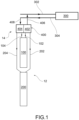
- Figure 1 schematically shows an apparatus 12 for moving bobbins and tubes in a textile plant 14 essentially comprising at least one group of at least two spinning machines 100; 200 and at least one winding machine 300.
- the apparatus 12 comprises an outward conveyor 102; 202, and a return conveyor 104; 204 for each spinning machine 100; 200, wherein the outward conveyor 102; 202 is adapted for transporting bobbins in output from the respective spinning machine 100, 200; and the return conveyor 104, 204 is adapted for transporting tubes entering the respective spinning machine 100, 200.
- the apparatus comprises a sorting device 400, which comprises a conveyor station 402 at which the outward conveyors 102; 202 converge, and a redistribution station 404 at which the return conveyors 104; 204 converge.
- a sorting device 400 which comprises a conveyor station 402 at which the outward conveyors 102; 202 converge, and a redistribution station 404 at which the return conveyors 104; 204 converge.
- the conveyor station 402 and the redistribution station 404 are connected by means of a conveyor 406 and a redistribution conveyor 408, respectively, to a bobbin input line 302 to the at least one winding machine 300 and to a bobbin output line 304 from the at least one winding machine 300.
- the conveyor station 406 and the redistribution station 408 are adapted for redistributing the bobbins or tubes respectively to the conveyor 406 or to the return conveyors 104; 204 based on predetermined operating parameters of the bobbins and tubes to be redistributed.
- the spinning machines 100; 200 are substantially aligned with each other.
- substantially aligned spinning machines means that the respective spinning heads of the spinning machines are substantially aligned with each other. In other words, the spinning machines are aligned with each other in a direction longitudinal to them.
- the outward 102 and return 104 conveyors of the spinning machine 100 placed in proximity to said sorting device 400 may be arranged internally with respect to the outward 202 and return 204 conveyors of the spinning machine 200 distal with respect to the sorting device 400.
- outward conveyors 102, 202 and the return conveyors 104, 204 may be arranged substantially parallel to each other.
- the spinning machines 100, 200 may have 300-600 heads.
- FIG. 2 shows an alternative embodiment of the apparatus of the present invention.
- At least one further spinning machine 250 may be arranged downstream of the sorting device 400, i.e. between the sorting device 400 and the at least one winding machine 300.
- the apparatus 14 therefore comprises an outward conveyor 252 and a return conveyor 254 for the at least one further spinning machine 250.
- Such conveyors 252, 254, together with the conveyor 406 and the redistribution conveyor 408 converge on a second sorting device 401, comprising a conveyor station 403 and a redistribution station 505.
- the second sorting device 401 may be entirely similar to the sorting device 400.
- the conveyor station 403 and the redistribution station 405 of the second sorting device 401 are connected by means of a conveyor 407 and a redistribution conveyor 409, respectively, to a bobbin input line 302 to the at least one winding machine 300 and to a bobbin output line 304 from the at least one winding machine 300.
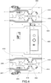
- the conveyor station 402 of the sorting device 400 may comprise a conveyor disc 410.
- the redistribution station 404 may also comprise a redistribution disc 412.
- the conveyor disc 410 and the redistribution disc 412 comprise at least one side seat 414, 416 adapted to engage a collar of a plate of a bobbin, and by rotating they move the plate from an input position to the relative station 402, 404 and an output position from the station 402, 404.
- the rotation of the conveyor disc 410 and of the redistribution disc 412 may take place in a manner known per se to those skilled in the art, for example through an actuator (not shown) operated by the central control unit 500 of the textile plant, or through a dedicated control unit (not shown).
- the conveyor disc 410 and/or the redistribution disc 412 may comprise six side seats 414, 416, as shown in the examples of Figures 4-7 .
- the conveyor disc 410 and/or the redistribution disc 412 may comprise three side seats 414, 416.
- the side seats 414, 416 are adapted to be engaged by a collar of a plate, so as to be able to be repositioned through a rotation of the conveyor disc 410 or of the redistribution disc 412.
- the disc with six side seats 414, 416 may be adapted to rotate in one direction only.
- control unit 500 of the textile plant may be adapted to manage these rotations, so that they are, for example, as short as possible, in terms of time or displacement.
- the conveyor station 402 and the redistribution station 404 may be of different types in the same sorting device 400.
- the conveyor station 402 may be provided at each outward conveyor 102, 202 with stops 209, 211 adapted to selectively block a plate.
- Said stops 209, 211 may be of a mechanical type, electrically or pneumatically actuated. In any case, said stops 209, 211 may be of a type known per se to those skilled in the art and therefore will not be further explored.
- the redistribution station 404 may comprise a diverter 213 adapted to divert the plates arriving from the winding machine to one of the return conveyors 104, 204.
- the diverter 213 may be, for example, of a mechanical type, and electrically or pneumatically operated. In any case, the diverter 213 may be of a type known per se to those skilled in the art and therefore will not be further described.
- a stop 203 may be provided on the outward conveyor 202 of the most distant spinning machine 200.
- Such stop 203 is suitable for preventing jams being created in proximity to the sorting disc and, at the same time, uses the same outward conveyor 202, which is longer, as a temporary storage system for the bobbins.
- the stop 203 may be of the pneumatic type.
- the stop 203 may be managed directly by the control unit 500.
- the return conveyor 104 of the spinning machine 100 closest to the sorting station 400 may be provided with a bypass conveyor 105 adapted to directly connect the return conveyor 104 to the outward conveyor 102 of the spinning machine 100.
- a diverter 107 is arranged in the vicinity of the fork between return conveyor 104 and bypass conveyor 105 suitable to divert the plates towards the return conveyor 104, or towards the bypass conveyor 105.
- the diverter 107 may be of a type known per se to those skilled in the art and therefore will not be further described.
- the winding machine will recirculate the empty tubes inside the winding machine itself until the spinning machine returns to operate.
- overflow sensors 205, 207 may be arranged, adapted to detect the presence of spools and to send this information to the central control unit 500 to stop the feeding of the bobbins to the relative conveyors, if necessary.
- these sensors may be optical presence photocells.
- the conveyor station 402 of the sorting device 400 may comprise at least one reading device 418 of the tracking device arranged on the plate associated with the tube. Said reading device 418 is adapted to read said tracking device arranged on the plate for the management of the plate and therefore of the bobbin associated therewith.
- the reading device 418 may be adapted to send this detected information to a central control unit 500 for managing the plate and therefore the bobbin associated therewith. Furthermore, the reading device 418 may be suitable for adding information to the tracking device arranged on the plate.
- the reading device 418 is arranged below the conveyor disc 410.
- the reading devices 418 may be two, one for each outward conveyor.
- the reading device 418 may be a radiofrequency reader.
- the reading device 418 may be a radiofrequency reader adapted to interact with a tracking device of the RFID type.
- the redistribution station 404 has the purpose of redistributing the tubes coming from at least one winding machine 300, to the corresponding spinning machine and, if the tube is not present, restoring it so that the empty tube always reaches the correct spinning machine ready to be wound in a new bobbin.
- the redistribution station 404 may comprise at least one reading device 420 adapted to detect and read a tracking device arranged on a plate associated with a tube.
- the reading device 420 may be adapted to send this detected information to a central control unit 500 for managing the bobbins.
- the reading device 420 may be arranged below the conveyor disc 410.
- the reading device 420 may be a radiofrequency reader.
- the reading device 420 may be a radiofrequency reader adapted to interact with a tracking device of the RFID type.
- the management system will evaluate where to direct the plate and will re-communicate it to the redistribution station 404 itself, allowing the plate to be correctly directed.
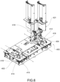
- a tube presence device 419, 421 adapted to assess whether there is a tube on the plate in transit. If it were absent, the device would place a new tube by fitting it appropriately on the plate in transit.
- Figures 1 , 2 and 3 show a textile plant 14 comprising at least one group of two spinning machines 100, 200 and at least one winding machine 300, which comprises an apparatus for moving bobbins and tubes of the type just described.
- the textile plant 14 comprises a bobbin input line 302 to the at least one winding machine 300, and a tube output line 304 from the at least one winding machine 300.
- the textile plant 14 may comprise a central control unit 500 for managing the bobbins and tubes connected to said at least one sorting device 400 and to said at least one winding machine 300.
- an apparatus for moving bobbins and tubes for a textile plant which may better adapt to the arrangements of the individual existing apparatuses.
- the possible spinning machine arrangements are much more versatile than the traditional Multilink model and also allow making better use of the limited space between the spinning machines.
- the apparatus according to the present invention is easily replicable, both in different systems but also within the same system, as may be seen in the example shown in Figure 3 .
- the apparatus according to the present invention allows already constituted textile plants to be improved, without the need to move the already installed spinning machines.
Landscapes
- Engineering & Computer Science (AREA)
- Mechanical Engineering (AREA)
- Textile Engineering (AREA)
- Replacing, Conveying, And Pick-Finding For Filamentary Materials (AREA)
- Spinning Or Twisting Of Yarns (AREA)
Description
- The present invention relates to an apparatus for moving bobbins and tubes for a textile plant, and a textile plant comprising such apparatus for moving bobbins and tubes.
- As is known, generally the Multilink type textile plants comprise a plurality of spinning machines which feed a winding machine, and a transport system for the bobbins for sending the bobbins from a spinning machine to the winding machine, and a transport system for the empty tubes arriving from the winding machine and destined for a specific spinning machine. As an example,
WO 2008/095662 A1 discloses a spinning mill system having at least two ring-spinning machines with automatic bobbin changing apparatus which deposit bobbins which have been pulled off onto a transport means, which can be driven and is guided along on the two longitudinal sides of each of the ring-spinning machines, and can remove empty tubes from said transport means, and having at least one automatic bobbin winder, wherein the transport means is common at least to the ring-spinning machines and the ring-spinning machines are connected via a control apparatus in such a way that a doffing process is not initiated until the control apparatus determines the end of the spinning process on both ring-spinning machines and the provision of the regions of the transport means with empty tubes and empty receiving journals for full bobbins with respect to the spindles which are to be doffed, and in which the ring-spinning machines are in a master/slave relationship such that one of the ring-spinning machines controls the work sequence also of the other ring-spinning machine/machines as master. - In this discussion, reference will be made to the handling of the bobbins or tubes, however, the handling of the bobbins takes place through systems suitable for the purpose, for example tube-plate systems, per se known to those skilled in the art.
- These systems provide a plate, arranged with a protruding portion, called collar, suitable for being partially inserted into a tube. The plate is guided by the transport system which essentially comprises a conveyor belt on which the plate is placed, and a guide suitable for coupling with the portion of the collar which is not contained inside the tube. The guide may be made, for example, by means of two portions of sheet metal placed side by side but spaced apart, in such a way as to identify a slot just wider than the diameter of the collar.
- In traditional systems of the Multilink type, the spinning machines are arranged parallel, with one end aligned, so that they may face a single shared transport system.
- Typically, the shared transport system is substantially composed of two conveyor belts, onto which the empty bobbins or tubes are loaded automatically. A first conveyor belt takes care of transporting the bobbins from the respective spinning machine to the winding machine, and a second conveyor belt takes care of transporting the empty tubes from the winding machine to the destination spinning machine.
- In this discussion, with conveyor belt or conveyor, we mean a system suitable for transporting the bobbins from one position to another. For this purpose, the conveyors may be of the type indicated above, and may comprise lanes on which the plates may be inserted, and a movable element such as a belt or a chain suitable for moving the plates from one position to another.
- Once the winding machine has completed the processing of the yarn by completely emptying the bobbin, the tube thus freed is positioned on the shared transport system and sent to the destination spinning machine.
- In this discussion the term thread or monofilament or continuous thread means a single filament or continuous strand (for example in the case of silk, artificial, or synthetic fibers), while the term "yarn" means the set of fibrils of variable length that are parallelized and joined by twisting. In the following, either term will be used indistinctly, it being understood that the applications of the present invention are not limited to one or the other type.
- Each bobbin, in order to be assigned correctly, is associated with a plate, on which a tracking device is generally placed which allows said plate and therefore the relative bobbin or tube to be associated to a specific winding unit or to a specific spinning machine.
- The transport systems for the bobbin or tubes of the prior art, although widely used and appreciated, are not free from drawbacks.
- For example, in the case in which the existing textile plant provides spinning machines aligned with each other, and not arranged in parallel with each other, since these are apparatuses of considerable size and complexity, it is not always possible, easy, or convenient from the economic point of view to change their arrangement over time.
- Moreover, precisely because of the position of the spinning machines, the system used to move the bobbins is a complex system, since each spinning machine unloads the bobbins independently of the other spinning machines on the same conveyor belt. Therefore, it is necessary to provide sophisticated systems to prevent the unloading of a bobbin by a spinning machine from conflicting with a bobbin of an unloading of a previous spinning machine which is already on the conveyor belt.
- Furthermore, the apparatuses currently used occupy a lot of floor area, which could instead be usable in another way.
- The need to solve at least partly the drawbacks and limitations mentioned with reference to the prior art is therefore felt.
- Therefore, the need is felt to provide an apparatus for moving bobbins and tubes for a textile plant, which allows better adaptation to the arrangements of the individual existing apparatuses.
- Furthermore, the need is felt for a system that simplifies the spinning machine-winding machine interconnection structure, reducing its overall dimensions and increasing the simplicity of the textile plant.
- Furthermore, the need is felt to make the bobbin and tube moving apparatus modular, so that it may be easily replicated in the case of a textile plant with many spinning machines.
- These requirements are met at least partially by an apparatus for moving bobbins and tubes for a textile plant according to claim 1, and by a textile plant comprising such apparatus according to claim 13.
- Further features and advantages of the present invention will become more apparent from the following description of preferred and non-limiting embodiments thereof, in which:
-
Figure 1 shows a schematic top plan view of an apparatus for moving bobbins and tubes for a textile plant according to a possible embodiment of the present invention; -
Figure 2 schematically shows a plan view of an apparatus for moving bobbins and tubes for a textile plant according to an alternative embodiment of the present invention; -
Figure 3 schematically shows a plan view of a textile plant according to a possible embodiment of the present invention; -
Figure 4 schematically shows a plan view of a component of an apparatus for moving bobbins and tubes for a textile plant according to a possible embodiment of the present invention; -
Figure 5 schematically shows a plan view of the component ofFigure 4 with some additional elements according to a possible embodiment; -
Figure 6 schematically shows a perspective view of the component ofFigure 5 ; and -
Figures 7-9 schematically show plan views of possible alternative embodiments of the component ofFigure 4 . - Elements or parts of elements common to the embodiments described hereinafter will be indicated with the same reference numerals.
-
Figure 1 schematically shows anapparatus 12 for moving bobbins and tubes in atextile plant 14 essentially comprising at least one group of at least twospinning machines 100; 200 and at least onewinding machine 300. - The
apparatus 12 comprises anoutward conveyor 102; 202, and areturn conveyor 104; 204 for eachspinning machine 100; 200, wherein theoutward conveyor 102; 202 is adapted for transporting bobbins in output from therespective spinning machine return conveyor respective spinning machine - Moreover, the apparatus comprises a
sorting device 400, which comprises aconveyor station 402 at which theoutward conveyors 102; 202 converge, and aredistribution station 404 at which thereturn conveyors 104; 204 converge. - The
conveyor station 402 and theredistribution station 404 are connected by means of aconveyor 406 and aredistribution conveyor 408, respectively, to abobbin input line 302 to the at least onewinding machine 300 and to abobbin output line 304 from the at least onewinding machine 300. - The
conveyor station 406 and theredistribution station 408 are adapted for redistributing the bobbins or tubes respectively to theconveyor 406 or to thereturn conveyors 104; 204 based on predetermined operating parameters of the bobbins and tubes to be redistributed. - As may be seen in
Figure 1 , thespinning machines 100; 200 are substantially aligned with each other. - In this discussion, the term substantially aligned spinning machines means that the respective spinning heads of the spinning machines are substantially aligned with each other. In other words, the spinning machines are aligned with each other in a direction longitudinal to them.
- According to a possible embodiment, the outward 102 and return 104 conveyors of the
spinning machine 100 placed in proximity to saidsorting device 400 may be arranged internally with respect to the outward 202 and return 204 conveyors of thespinning machine 200 distal with respect to thesorting device 400. - As may be seen in
Figures 1-3 , theoutward conveyors return conveyors - By way of example only, the
spinning machines -
Figure 2 shows an alternative embodiment of the apparatus of the present invention. - As may be seen in
Figure 2 , downstream of thesorting device 400, i.e. between thesorting device 400 and the at least onewinding machine 300, at least onefurther spinning machine 250 may be arranged. - The
apparatus 14 therefore comprises anoutward conveyor 252 and areturn conveyor 254 for the at least onefurther spinning machine 250.Such conveyors conveyor 406 and theredistribution conveyor 408 converge on asecond sorting device 401, comprising aconveyor station 403 and a redistribution station 505. - Advantageously, the
second sorting device 401 may be entirely similar to thesorting device 400. - The
conveyor station 403 and theredistribution station 405 of thesecond sorting device 401 are connected by means of aconveyor 407 and aredistribution conveyor 409, respectively, to abobbin input line 302 to the at least onewinding machine 300 and to abobbin output line 304 from the at least onewinding machine 300. - According to a possible embodiment, the
conveyor station 402 of thesorting device 400 may comprise aconveyor disc 410. Furthermore, theredistribution station 404 may also comprise aredistribution disc 412. - The
conveyor disc 410 and theredistribution disc 412 comprise at least oneside seat relative station station - The rotation of the
conveyor disc 410 and of theredistribution disc 412 may take place in a manner known per se to those skilled in the art, for example through an actuator (not shown) operated by thecentral control unit 500 of the textile plant, or through a dedicated control unit (not shown). - Advantageously, the
conveyor disc 410 and/or theredistribution disc 412 may comprise sixside seats Figures 4-7 . - According to a possible alternative embodiment shown in
Figure 9 , theconveyor disc 410 and/or theredistribution disc 412 may comprise threeside seats - The
side seats conveyor disc 410 or of theredistribution disc 412. - According to a possible embodiment, the disc with six
side seats - On the other hand, as regards the embodiment which provides a disc with three
side seats - In both cases, the
control unit 500 of the textile plant may be adapted to manage these rotations, so that they are, for example, as short as possible, in terms of time or displacement. - According to a possible embodiment, the
conveyor station 402 and theredistribution station 404 may be of different types in thesame sorting device 400. - According to a possible embodiment, which may be seen for example in
Figure 8 , theconveyor station 402 may be provided at eachoutward conveyor stops - Again with reference to
Figure 8 , theredistribution station 404 may comprise adiverter 213 adapted to divert the plates arriving from the winding machine to one of thereturn conveyors diverter 213 may be, for example, of a mechanical type, and electrically or pneumatically operated. In any case, thediverter 213 may be of a type known per se to those skilled in the art and therefore will not be further described. - As previously mentioned, the
conveyor station 402 of thesorting device 400 receives the bobbins arranged on their tube and respective plate in output from thespinning machines stop 203 may be provided on theoutward conveyor 202 of the mostdistant spinning machine 200.Such stop 203 is suitable for preventing jams being created in proximity to the sorting disc and, at the same time, uses the sameoutward conveyor 202, which is longer, as a temporary storage system for the bobbins. Advantageously, thestop 203 may be of the pneumatic type. Furthermore, thestop 203 may be managed directly by thecontrol unit 500. - According to a possible embodiment, shown for example in
Figure 7 , thereturn conveyor 104 of the spinningmachine 100 closest to the sortingstation 400 may be provided with abypass conveyor 105 adapted to directly connect thereturn conveyor 104 to theoutward conveyor 102 of the spinningmachine 100. Adiverter 107 is arranged in the vicinity of the fork betweenreturn conveyor 104 andbypass conveyor 105 suitable to divert the plates towards thereturn conveyor 104, or towards thebypass conveyor 105. - The
diverter 107 may be of a type known per se to those skilled in the art and therefore will not be further described. - The operation of the
bypass conveyor 105 provides that in the event that the spinning machine closest to the sortingstation 400 is not able to receive empty tubes, these are sent to theconveyor station 402 to be sent back to the windingmachine 300. The windingmachine 300, detecting the presence of an empty tube, will send it back to the spinning machine. Advantageously, the process may be repeated until the spinning machine returns to operate to receive a tube. - In other words, according to a possible embodiment, the winding machine will recirculate the empty tubes inside the winding machine itself until the spinning machine returns to operate.
- According to a possible embodiment, in both the
outward conveyors spinning machines overflow sensors central control unit 500 to stop the feeding of the bobbins to the relative conveyors, if necessary. Advantageously, these sensors may be optical presence photocells. - According to a possible embodiment, the
conveyor station 402 of thesorting device 400 may comprise at least onereading device 418 of the tracking device arranged on the plate associated with the tube. Saidreading device 418 is adapted to read said tracking device arranged on the plate for the management of the plate and therefore of the bobbin associated therewith. - According to a possible embodiment, the
reading device 418 may be adapted to send this detected information to acentral control unit 500 for managing the plate and therefore the bobbin associated therewith. Furthermore, thereading device 418 may be suitable for adding information to the tracking device arranged on the plate. - According to a possible embodiment, the
reading device 418 is arranged below theconveyor disc 410. Advantageously, thereading devices 418 may be two, one for each outward conveyor. - Advantageously, the
reading device 418 may be a radiofrequency reader. In particular, thereading device 418 may be a radiofrequency reader adapted to interact with a tracking device of the RFID type. - The
redistribution station 404 has the purpose of redistributing the tubes coming from at least one windingmachine 300, to the corresponding spinning machine and, if the tube is not present, restoring it so that the empty tube always reaches the correct spinning machine ready to be wound in a new bobbin. - To suitably carry out the directing, the
redistribution station 404 may comprise at least onereading device 420 adapted to detect and read a tracking device arranged on a plate associated with a tube. Thereading device 420 may be adapted to send this detected information to acentral control unit 500 for managing the bobbins. - According to a possible embodiment, the
reading device 420 may be arranged below theconveyor disc 410. - Advantageously, the
reading device 420 may be a radiofrequency reader. In particular, thereading device 420 may be a radiofrequency reader adapted to interact with a tracking device of the RFID type. - The management system will evaluate where to direct the plate and will re-communicate it to the
redistribution station 404 itself, allowing the plate to be correctly directed. - According to a possible embodiment, shown for example in
Figures 5 and6 , downstream of theredistribution disc 412, for eachreturn conveyor spinning machines tube presence device -
Figures 1 ,2 and3 show atextile plant 14 comprising at least one group of two spinningmachines machine 300, which comprises an apparatus for moving bobbins and tubes of the type just described. - As may be seen in
Figures 1 ,2 , and3 , thetextile plant 14 comprises abobbin input line 302 to the at least one windingmachine 300, and atube output line 304 from the at least one windingmachine 300. - Furthermore, the
textile plant 14 may comprise acentral control unit 500 for managing the bobbins and tubes connected to said at least onesorting device 400 and to said at least one windingmachine 300. - The advantages of an apparatus according to the present invention are therefore now apparent.
- In the first place, an apparatus has been provided for moving bobbins and tubes for a textile plant which may better adapt to the arrangements of the individual existing apparatuses.
- In other words, the possible spinning machine arrangements are much more versatile than the traditional Multilink model and also allow making better use of the limited space between the spinning machines.
- Furthermore, the apparatus according to the present invention is easily replicable, both in different systems but also within the same system, as may be seen in the example shown in
Figure 3 . - Furthermore, the apparatus according to the present invention allows already constituted textile plants to be improved, without the need to move the already installed spinning machines.
- A person skilled in the art may make modifications to the embodiments described above or substitute described elements with equivalent elements, in order to satisfy particular requirements, without departing from the scope of the accompanying claims.
Claims (14)
- Apparatus (12) for moving bobbins and tubes in a textile plant (14) comprising at least one group of at least two spinning machines (100; 200) and at least one winding machine (300);said apparatus (12) comprising:- an outward conveyor (102; 202), and a return conveyor (104; 204) for each spinning machine (100; 200); said outward conveyor (102; 202) being adapted for transporting bobbins in output from the respective spinning machine (100, 200); said return conveyor (104, 204) being adapted for transporting tubes entering the respective spinning machine (100, 200);- a sorting device (400) comprising a conveyor station (402) at which the outward conveyors (102; 202) converge, and a redistribution station (404) at which the return conveyors (104; 204) converge;said conveyor station (402) and said redistribution station (404) being connected by means of a conveyor (406) and a redistribution conveyor (408) respectively to a bobbin input line (302) to said at least one winding machine (300) and to a bobbin output line (304) from said at least one winding machine (300);said conveyor station (402) and said redistribution station (408) being adapted for redistributing the bobbins or tubes respectively to the bobbin input line (302) or to the return conveyors (104; 204) based on predetermined operating parameters of the bobbins and tubes to be redistributed;wherein said spinning machines (100; 200) are aligned with each other in a direction longitudinal to them.
- Apparatus (12) according to the preceding claim, characterized in that it comprises, downstream of the sorting device (400) at least one further spinning machine (250), the apparatus (12) comprising an outward conveyor (252) and a return conveyor (254) associated with said at least one further spinning machine (250), which together with the conveyor (406) and the redistribution conveyor (408) associated with the sorting device (400) converge on a second sorting device (401), comprising a conveyor station (403) and a redistribution station (409), said conveyor station (403) and said redistribution station (405) of the second sorting device (401) being connected by means of a conveyor (407) and a redistribution conveyor (409) respectively to a bobbin input line (302) to the at least one winding machine (300), and to a tube output line (304) from the at least one winding machine (300).
- Apparatus (12) according to any one of the preceding claims, characterized in that said conveyor station (402) comprises a conveyor disc (410) provided with at least one side seat (414), adapted to engage a collar of a plate, to rotate it from an input position to said conveyor station (402) to an output position from said conveyor station (402).
- Apparatus (12) according to any one of the preceding claims, characterized in that said redistribution station (404) comprises a redistribution disc (412) provided with at least one side seat (416) adapted to engage a collar of a plate, to rotate it from an input position to said redistribution station (404) to an output position from said redistribution station (404).
- Apparatus (12) according to any one of claims 3-4, characterized in that said conveyor disc (410) and/or said redistribution disc (412) comprise three or six side seats (414, 416).
- Apparatus (12) according to any one of the preceding claims, characterized in that said conveyor station (402) is provided at each outward conveyor (102, 202) with stops (209, 211) adapted to selectively block a plate, said stops (209, 211) being of a mechanical type, actuated electrically or pneumatically.
- Apparatus (12) according to any one of the preceding claims, characterized in that said redistribution station (404) comprises a diverter (213) adapted to divert the plates arriving from the at least one winding machine (300) to one of the return conveyors (104, 204), said diverter (213) being of a mechanical type, electrically actuated or pneumatically actuated.
- Apparatus (12) according to any one of the preceding claims, characterized in that said conveyor station (402) of the sorting device (400) is provided with at least one device (418) for reading a tracking device arranged on a plate and sending the detected information to a central control unit (500).
- Apparatus (12) according to any one of the preceding claims, characterized in that said redistribution station (404) comprises at least one reading device (420) adapted to detect and read a tracking device provided on a plate, and to send the detected information to a central control unit (500).
- Apparatus (12) according to any one of claims 8-9, characterized in that said reader devices (418, 420) are a radio frequency reader suitable to interact with an RFID-type tracking device.
- Apparatus (12) according to any one of the preceding claims, characterized in that the return conveyor (104) of the spinning machine (100) closest to the sorting station (400) may be provided with a bypass conveyor (105) adapted to directly connect the return conveyor (104) to the outward conveyor (102) of the spinning machine (100), said apparatus (12) comprising a diverter (107) in the vicinity of the fork between return conveyor (104) and bypass conveyor (105) suitable to divert the plates towards the return conveyor (104), or towards the bypass conveyor (105).
- Textile plant (14) characterized in that it comprises at least one group of at least two spinning machines (100, 200) and at least one winding machine (300) characterized in that it comprises an apparatus for moving bobbins in a textile plant according to any one of the preceding claims.
- Textile plant (14) according to the preceding claim, characterized in that it comprises a bobbin input line (302) to said at least one winding machine (300), and a tube output line (304) from said at least one winding machine (300).
- Textile plant (14) according to any one of claims 12-13, characterized in that it comprises a central control unit (500) for managing bobbins connected to said at least one sorting device (400) and to said at least one winding machine (300).
Applications Claiming Priority (1)
| Application Number | Priority Date | Filing Date | Title |
|---|---|---|---|
| IT102020000030203A IT202000030203A1 (en) | 2020-12-09 | 2020-12-09 | EQUIPMENT FOR HANDLING BOBBINS AND TUBES FOR A TEXTILE PLANT, AND TEXTILE PLANT INCLUDING THIS EQUIPMENT |
Publications (2)
| Publication Number | Publication Date |
|---|---|
| EP4011814A1 EP4011814A1 (en) | 2022-06-15 |
| EP4011814B1 true EP4011814B1 (en) | 2025-05-21 |
Family
ID=74874989
Family Applications (1)
| Application Number | Title | Priority Date | Filing Date |
|---|---|---|---|
| EP21211387.2A Active EP4011814B1 (en) | 2020-12-09 | 2021-11-30 | Apparatus for moving bobbins and tubes for a textile plant, and a textile plant comprising such apparatus |
Country Status (3)
| Country | Link |
|---|---|
| EP (1) | EP4011814B1 (en) |
| CN (2) | CN114622310A (en) |
| IT (1) | IT202000030203A1 (en) |
Families Citing this family (1)
| Publication number | Priority date | Publication date | Assignee | Title |
|---|---|---|---|---|
| IT202000030203A1 (en) * | 2020-12-09 | 2022-06-09 | Savio Macch Tessili Spa | EQUIPMENT FOR HANDLING BOBBINS AND TUBES FOR A TEXTILE PLANT, AND TEXTILE PLANT INCLUDING THIS EQUIPMENT |
Citations (1)
| Publication number | Priority date | Publication date | Assignee | Title |
|---|---|---|---|---|
| WO2008095662A1 (en) * | 2007-02-09 | 2008-08-14 | Oerlikon Textile Gmbh & Co. Kg | Spinning mill system having at least two ring-spinning machines and at least one master/slave arrangement |
Family Cites Families (8)
| Publication number | Priority date | Publication date | Assignee | Title |
|---|---|---|---|---|
| JPS5912051A (en) * | 1982-07-14 | 1984-01-21 | Murata Mach Ltd | Conveying system of different-type cops |
| US4854453A (en) * | 1982-12-08 | 1989-08-08 | Murata Kikai Kabushiki Kaisha | Article selecting and conveying system |
| JPS6052632A (en) * | 1983-08-25 | 1985-03-25 | Murata Mach Ltd | Winder for fine spinning |
| JPH0662255B2 (en) * | 1985-05-20 | 1994-08-17 | 村田機械株式会社 | Bobbin transport system |
| US5269478A (en) * | 1991-05-23 | 1993-12-14 | Murata Kikai Kabushiki Kaisha | Bobbin trace system |
| IT1283270B1 (en) * | 1996-03-18 | 1998-04-16 | Savio Macchine Tessili Spa | PROCEDURE AND DEVICE FOR CONTEMPORARY WINDING OF A MULTIPLE LOTS OF YARN |
| DE102007028650A1 (en) * | 2007-06-21 | 2008-12-24 | Oerlikon Textile Gmbh & Co. Kg | Feed cups distributing device for automatic winding machine, has control device controlling driving of distribution units in required rotational direction according to forward conveying direction of feed cups |
| IT202000030203A1 (en) * | 2020-12-09 | 2022-06-09 | Savio Macch Tessili Spa | EQUIPMENT FOR HANDLING BOBBINS AND TUBES FOR A TEXTILE PLANT, AND TEXTILE PLANT INCLUDING THIS EQUIPMENT |
-
2020
- 2020-12-09 IT IT102020000030203A patent/IT202000030203A1/en unknown
-
2021
- 2021-11-30 EP EP21211387.2A patent/EP4011814B1/en active Active
- 2021-12-08 CN CN202111494174.4A patent/CN114622310A/en active Pending
- 2021-12-08 CN CN202123072820.6U patent/CN216947332U/en active Active
Patent Citations (1)
| Publication number | Priority date | Publication date | Assignee | Title |
|---|---|---|---|---|
| WO2008095662A1 (en) * | 2007-02-09 | 2008-08-14 | Oerlikon Textile Gmbh & Co. Kg | Spinning mill system having at least two ring-spinning machines and at least one master/slave arrangement |
Also Published As
| Publication number | Publication date |
|---|---|
| CN216947332U (en) | 2022-07-12 |
| EP4011814A1 (en) | 2022-06-15 |
| CN114622310A (en) | 2022-06-14 |
| IT202000030203A1 (en) | 2022-06-09 |
Similar Documents
| Publication | Publication Date | Title |
|---|---|---|
| US4634066A (en) | Article conveying and handling system | |
| US4848076A (en) | Interconnecting system for a winder and a two-for-one twisting machine | |
| US5497952A (en) | Automatic bobbin winder having processors for yarn end preparation information | |
| CN101327881B (en) | Apparatus for distributing transportation plates for weft bobbin as well as empty and partly wound tube | |
| EP4015429B1 (en) | Bobbin-changing device for finishing machine such as a winding machine and related finishing machine | |
| US5308001A (en) | Transport system for circulating and accumulating tube support members in association with a bobbin winding machine | |
| CN108657883A (en) | Method and textile machinery for the cross winding unit feeding spool for textile machinery | |
| US5582354A (en) | Cheese-producing textile machine | |
| US6290165B1 (en) | Automatic cheese winder and method for operating an automatic cheese winder | |
| US6098914A (en) | System for moving spools and tubes in automatic spoolers | |
| EP3279123B1 (en) | Method and device for supplying empty tubes to attending devices of a textile machine | |
| EP4011814A1 (en) | Apparatus for moving bobbins and tubes for a textile plant, and a textile plant comprising such apparatus | |
| DE102012016482A1 (en) | Spinnkops- and sleeve transport system for a cheese-making textile machine | |
| JPH01229829A (en) | Method and apparatus for replacing roving bobbin on fiber machine | |
| US5179829A (en) | Combined textile yarn spinning and winding system having spinning tube transporting means | |
| US5423493A (en) | Method for operating an automatic bobbin-winding machine during batch changing operations | |
| US5443165A (en) | Bobbin feeding system of automatic winder | |
| US4610406A (en) | Bobbin supplying system | |
| CN113443524B (en) | Textile machine for producing cross-wound bobbins and method for operating the same | |
| US5323979A (en) | Method for operating an automatic bobbin winding machine | |
| US20010004999A1 (en) | Interface in the transport system of a textile machine producing cross-wound bobbins | |
| CN111646295B (en) | Multi-variety cop processing device for bobbin yarn conveying line of bobbin winder and conveying line | |
| US5398878A (en) | Method and apparatus for producing a predetermined number of full yarn packages on an automatic winder | |
| CN111348482B (en) | Combined system with at least two supply units and at least one winding machine | |
| US6089494A (en) | Bobbin transport system for a bobbin winding machine |
Legal Events
| Date | Code | Title | Description |
|---|---|---|---|
| PUAI | Public reference made under article 153(3) epc to a published international application that has entered the european phase |
Free format text: ORIGINAL CODE: 0009012 |
|
| STAA | Information on the status of an ep patent application or granted ep patent |
Free format text: STATUS: THE APPLICATION HAS BEEN PUBLISHED |
|
| AK | Designated contracting states |
Kind code of ref document: A1 Designated state(s): AL AT BE BG CH CY CZ DE DK EE ES FI FR GB GR HR HU IE IS IT LI LT LU LV MC MK MT NL NO PL PT RO RS SE SI SK SM TR |
|
| STAA | Information on the status of an ep patent application or granted ep patent |
Free format text: STATUS: REQUEST FOR EXAMINATION WAS MADE |
|
| 17P | Request for examination filed |
Effective date: 20221213 |
|
| RBV | Designated contracting states (corrected) |
Designated state(s): AL AT BE BG CH CY CZ DE DK EE ES FI FR GB GR HR HU IE IS IT LI LT LU LV MC MK MT NL NO PL PT RO RS SE SI SK SM TR |
|
| STAA | Information on the status of an ep patent application or granted ep patent |
Free format text: STATUS: EXAMINATION IS IN PROGRESS |
|
| P01 | Opt-out of the competence of the unified patent court (upc) registered |
Effective date: 20230526 |
|
| 17Q | First examination report despatched |
Effective date: 20230613 |
|
| GRAP | Despatch of communication of intention to grant a patent |
Free format text: ORIGINAL CODE: EPIDOSNIGR1 |
|
| STAA | Information on the status of an ep patent application or granted ep patent |
Free format text: STATUS: GRANT OF PATENT IS INTENDED |
|
| INTG | Intention to grant announced |
Effective date: 20241218 |
|
| GRAS | Grant fee paid |
Free format text: ORIGINAL CODE: EPIDOSNIGR3 |
|
| GRAA | (expected) grant |
Free format text: ORIGINAL CODE: 0009210 |
|
| STAA | Information on the status of an ep patent application or granted ep patent |
Free format text: STATUS: THE PATENT HAS BEEN GRANTED |
|
| AK | Designated contracting states |
Kind code of ref document: B1 Designated state(s): AL AT BE BG CH CY CZ DE DK EE ES FI FR GB GR HR HU IE IS IT LI LT LU LV MC MK MT NL NO PL PT RO RS SE SI SK SM TR |
|
| REG | Reference to a national code |
Ref country code: GB Ref legal event code: FG4D |
|
| REG | Reference to a national code |
Ref country code: CH Ref legal event code: EP |
|
| REG | Reference to a national code |
Ref country code: DE Ref legal event code: R096 Ref document number: 602021031062 Country of ref document: DE |
|
| REG | Reference to a national code |
Ref country code: IE Ref legal event code: FG4D |
|
| REG | Reference to a national code |
Ref country code: NL Ref legal event code: MP Effective date: 20250521 |
|
| PG25 | Lapsed in a contracting state [announced via postgrant information from national office to epo] |
Ref country code: FI Free format text: LAPSE BECAUSE OF FAILURE TO SUBMIT A TRANSLATION OF THE DESCRIPTION OR TO PAY THE FEE WITHIN THE PRESCRIBED TIME-LIMIT Effective date: 20250521 Ref country code: ES Free format text: LAPSE BECAUSE OF FAILURE TO SUBMIT A TRANSLATION OF THE DESCRIPTION OR TO PAY THE FEE WITHIN THE PRESCRIBED TIME-LIMIT Effective date: 20250521 Ref country code: PT Free format text: LAPSE BECAUSE OF FAILURE TO SUBMIT A TRANSLATION OF THE DESCRIPTION OR TO PAY THE FEE WITHIN THE PRESCRIBED TIME-LIMIT Effective date: 20250922 |
|
| REG | Reference to a national code |
Ref country code: LT Ref legal event code: MG9D |
|
| PG25 | Lapsed in a contracting state [announced via postgrant information from national office to epo] |
Ref country code: GR Free format text: LAPSE BECAUSE OF FAILURE TO SUBMIT A TRANSLATION OF THE DESCRIPTION OR TO PAY THE FEE WITHIN THE PRESCRIBED TIME-LIMIT Effective date: 20250822 Ref country code: NO Free format text: LAPSE BECAUSE OF FAILURE TO SUBMIT A TRANSLATION OF THE DESCRIPTION OR TO PAY THE FEE WITHIN THE PRESCRIBED TIME-LIMIT Effective date: 20250821 |
|
| PG25 | Lapsed in a contracting state [announced via postgrant information from national office to epo] |
Ref country code: PL Free format text: LAPSE BECAUSE OF FAILURE TO SUBMIT A TRANSLATION OF THE DESCRIPTION OR TO PAY THE FEE WITHIN THE PRESCRIBED TIME-LIMIT Effective date: 20250521 Ref country code: NL Free format text: LAPSE BECAUSE OF FAILURE TO SUBMIT A TRANSLATION OF THE DESCRIPTION OR TO PAY THE FEE WITHIN THE PRESCRIBED TIME-LIMIT Effective date: 20250521 |
|
| PG25 | Lapsed in a contracting state [announced via postgrant information from national office to epo] |
Ref country code: BG Free format text: LAPSE BECAUSE OF FAILURE TO SUBMIT A TRANSLATION OF THE DESCRIPTION OR TO PAY THE FEE WITHIN THE PRESCRIBED TIME-LIMIT Effective date: 20250521 |
|
| PG25 | Lapsed in a contracting state [announced via postgrant information from national office to epo] |
Ref country code: HR Free format text: LAPSE BECAUSE OF FAILURE TO SUBMIT A TRANSLATION OF THE DESCRIPTION OR TO PAY THE FEE WITHIN THE PRESCRIBED TIME-LIMIT Effective date: 20250521 |
|
| PG25 | Lapsed in a contracting state [announced via postgrant information from national office to epo] |
Ref country code: RS Free format text: LAPSE BECAUSE OF FAILURE TO SUBMIT A TRANSLATION OF THE DESCRIPTION OR TO PAY THE FEE WITHIN THE PRESCRIBED TIME-LIMIT Effective date: 20250821 |
|
| PG25 | Lapsed in a contracting state [announced via postgrant information from national office to epo] |
Ref country code: IS Free format text: LAPSE BECAUSE OF FAILURE TO SUBMIT A TRANSLATION OF THE DESCRIPTION OR TO PAY THE FEE WITHIN THE PRESCRIBED TIME-LIMIT Effective date: 20250921 |
|
| PG25 | Lapsed in a contracting state [announced via postgrant information from national office to epo] |
Ref country code: LV Free format text: LAPSE BECAUSE OF FAILURE TO SUBMIT A TRANSLATION OF THE DESCRIPTION OR TO PAY THE FEE WITHIN THE PRESCRIBED TIME-LIMIT Effective date: 20250521 |
|
| REG | Reference to a national code |
Ref country code: AT Ref legal event code: MK05 Ref document number: 1796607 Country of ref document: AT Kind code of ref document: T Effective date: 20250521 |
|
| PGFP | Annual fee paid to national office [announced via postgrant information from national office to epo] |
Ref country code: DE Payment date: 20251125 Year of fee payment: 5 |
|
| PG25 | Lapsed in a contracting state [announced via postgrant information from national office to epo] |
Ref country code: DK Free format text: LAPSE BECAUSE OF FAILURE TO SUBMIT A TRANSLATION OF THE DESCRIPTION OR TO PAY THE FEE WITHIN THE PRESCRIBED TIME-LIMIT Effective date: 20250521 Ref country code: AT Free format text: LAPSE BECAUSE OF FAILURE TO SUBMIT A TRANSLATION OF THE DESCRIPTION OR TO PAY THE FEE WITHIN THE PRESCRIBED TIME-LIMIT Effective date: 20250521 Ref country code: SM Free format text: LAPSE BECAUSE OF FAILURE TO SUBMIT A TRANSLATION OF THE DESCRIPTION OR TO PAY THE FEE WITHIN THE PRESCRIBED TIME-LIMIT Effective date: 20250521 |
|
| PGFP | Annual fee paid to national office [announced via postgrant information from national office to epo] |
Ref country code: IT Payment date: 20251027 Year of fee payment: 5 |
|
| PGFP | Annual fee paid to national office [announced via postgrant information from national office to epo] |
Ref country code: TR Payment date: 20251103 Year of fee payment: 5 |
|
| PG25 | Lapsed in a contracting state [announced via postgrant information from national office to epo] |
Ref country code: CZ Free format text: LAPSE BECAUSE OF FAILURE TO SUBMIT A TRANSLATION OF THE DESCRIPTION OR TO PAY THE FEE WITHIN THE PRESCRIBED TIME-LIMIT Effective date: 20250521 |
|
| PG25 | Lapsed in a contracting state [announced via postgrant information from national office to epo] |
Ref country code: EE Free format text: LAPSE BECAUSE OF FAILURE TO SUBMIT A TRANSLATION OF THE DESCRIPTION OR TO PAY THE FEE WITHIN THE PRESCRIBED TIME-LIMIT Effective date: 20250521 |
|
| PG25 | Lapsed in a contracting state [announced via postgrant information from national office to epo] |
Ref country code: SK Free format text: LAPSE BECAUSE OF FAILURE TO SUBMIT A TRANSLATION OF THE DESCRIPTION OR TO PAY THE FEE WITHIN THE PRESCRIBED TIME-LIMIT Effective date: 20250521 Ref country code: RO Free format text: LAPSE BECAUSE OF FAILURE TO SUBMIT A TRANSLATION OF THE DESCRIPTION OR TO PAY THE FEE WITHIN THE PRESCRIBED TIME-LIMIT Effective date: 20250521 |
|
| REG | Reference to a national code |
Ref country code: DE Ref legal event code: R097 Ref document number: 602021031062 Country of ref document: DE |
|
| PLBE | No opposition filed within time limit |
Free format text: ORIGINAL CODE: 0009261 |
|
| STAA | Information on the status of an ep patent application or granted ep patent |
Free format text: STATUS: NO OPPOSITION FILED WITHIN TIME LIMIT |
|
| REG | Reference to a national code |
Ref country code: CH Ref legal event code: L10 Free format text: ST27 STATUS EVENT CODE: U-0-0-L10-L00 (AS PROVIDED BY THE NATIONAL OFFICE) Effective date: 20260402 |
|
| 26N | No opposition filed |
Effective date: 20260224 |