EP4011683A2 - Marine vessel power supply system, marine vessel and marine vessel power supply method - Google Patents
Marine vessel power supply system, marine vessel and marine vessel power supply method Download PDFInfo
- Publication number
- EP4011683A2 EP4011683A2 EP21203705.5A EP21203705A EP4011683A2 EP 4011683 A2 EP4011683 A2 EP 4011683A2 EP 21203705 A EP21203705 A EP 21203705A EP 4011683 A2 EP4011683 A2 EP 4011683A2
- Authority
- EP
- European Patent Office
- Prior art keywords
- inverter
- marine vessel
- battery
- electric power
- electric
- Prior art date
- Legal status (The legal status is an assumption and is not a legal conclusion. Google has not performed a legal analysis and makes no representation as to the accuracy of the status listed.)
- Pending
Links
Images


Classifications
-
- B—PERFORMING OPERATIONS; TRANSPORTING
- B60—VEHICLES IN GENERAL
- B60L—PROPULSION OF ELECTRICALLY-PROPELLED VEHICLES; SUPPLYING ELECTRIC POWER FOR AUXILIARY EQUIPMENT OF ELECTRICALLY-PROPELLED VEHICLES; ELECTRODYNAMIC BRAKE SYSTEMS FOR VEHICLES IN GENERAL; MAGNETIC SUSPENSION OR LEVITATION FOR VEHICLES; MONITORING OPERATING VARIABLES OF ELECTRICALLY-PROPELLED VEHICLES; ELECTRIC SAFETY DEVICES FOR ELECTRICALLY-PROPELLED VEHICLES
- B60L58/00—Methods or circuit arrangements for monitoring or controlling batteries or fuel cells, specially adapted for electric vehicles
- B60L58/10—Methods or circuit arrangements for monitoring or controlling batteries or fuel cells, specially adapted for electric vehicles for monitoring or controlling batteries
- B60L58/12—Methods or circuit arrangements for monitoring or controlling batteries or fuel cells, specially adapted for electric vehicles for monitoring or controlling batteries responding to state of charge [SoC]
-
- B—PERFORMING OPERATIONS; TRANSPORTING
- B60—VEHICLES IN GENERAL
- B60L—PROPULSION OF ELECTRICALLY-PROPELLED VEHICLES; SUPPLYING ELECTRIC POWER FOR AUXILIARY EQUIPMENT OF ELECTRICALLY-PROPELLED VEHICLES; ELECTRODYNAMIC BRAKE SYSTEMS FOR VEHICLES IN GENERAL; MAGNETIC SUSPENSION OR LEVITATION FOR VEHICLES; MONITORING OPERATING VARIABLES OF ELECTRICALLY-PROPELLED VEHICLES; ELECTRIC SAFETY DEVICES FOR ELECTRICALLY-PROPELLED VEHICLES
- B60L50/00—Electric propulsion with power supplied within the vehicle
- B60L50/10—Electric propulsion with power supplied within the vehicle using propulsion power supplied by engine-driven generators, e.g. generators driven by combustion engines
- B60L50/15—Electric propulsion with power supplied within the vehicle using propulsion power supplied by engine-driven generators, e.g. generators driven by combustion engines with additional electric power supply
-
- B—PERFORMING OPERATIONS; TRANSPORTING
- B60—VEHICLES IN GENERAL
- B60L—PROPULSION OF ELECTRICALLY-PROPELLED VEHICLES; SUPPLYING ELECTRIC POWER FOR AUXILIARY EQUIPMENT OF ELECTRICALLY-PROPELLED VEHICLES; ELECTRODYNAMIC BRAKE SYSTEMS FOR VEHICLES IN GENERAL; MAGNETIC SUSPENSION OR LEVITATION FOR VEHICLES; MONITORING OPERATING VARIABLES OF ELECTRICALLY-PROPELLED VEHICLES; ELECTRIC SAFETY DEVICES FOR ELECTRICALLY-PROPELLED VEHICLES
- B60L50/00—Electric propulsion with power supplied within the vehicle
- B60L50/10—Electric propulsion with power supplied within the vehicle using propulsion power supplied by engine-driven generators, e.g. generators driven by combustion engines
- B60L50/16—Electric propulsion with power supplied within the vehicle using propulsion power supplied by engine-driven generators, e.g. generators driven by combustion engines with provision for separate direct mechanical propulsion
-
- B—PERFORMING OPERATIONS; TRANSPORTING
- B63—SHIPS OR OTHER WATERBORNE VESSELS; RELATED EQUIPMENT
- B63H—MARINE PROPULSION OR STEERING
- B63H20/00—Outboard propulsion units, e.g. outboard motors or Z-drives; Arrangements thereof on vessels
- B63H20/14—Transmission between propulsion power unit and propulsion element
-
- B—PERFORMING OPERATIONS; TRANSPORTING
- B60—VEHICLES IN GENERAL
- B60L—PROPULSION OF ELECTRICALLY-PROPELLED VEHICLES; SUPPLYING ELECTRIC POWER FOR AUXILIARY EQUIPMENT OF ELECTRICALLY-PROPELLED VEHICLES; ELECTRODYNAMIC BRAKE SYSTEMS FOR VEHICLES IN GENERAL; MAGNETIC SUSPENSION OR LEVITATION FOR VEHICLES; MONITORING OPERATING VARIABLES OF ELECTRICALLY-PROPELLED VEHICLES; ELECTRIC SAFETY DEVICES FOR ELECTRICALLY-PROPELLED VEHICLES
- B60L2200/00—Type of vehicles
- B60L2200/32—Waterborne vessels
-
- B—PERFORMING OPERATIONS; TRANSPORTING
- B60—VEHICLES IN GENERAL
- B60L—PROPULSION OF ELECTRICALLY-PROPELLED VEHICLES; SUPPLYING ELECTRIC POWER FOR AUXILIARY EQUIPMENT OF ELECTRICALLY-PROPELLED VEHICLES; ELECTRODYNAMIC BRAKE SYSTEMS FOR VEHICLES IN GENERAL; MAGNETIC SUSPENSION OR LEVITATION FOR VEHICLES; MONITORING OPERATING VARIABLES OF ELECTRICALLY-PROPELLED VEHICLES; ELECTRIC SAFETY DEVICES FOR ELECTRICALLY-PROPELLED VEHICLES
- B60L2240/00—Control parameters of input or output; Target parameters
- B60L2240/40—Drive Train control parameters
- B60L2240/42—Drive Train control parameters related to electric machines
- B60L2240/425—Temperature
-
- B—PERFORMING OPERATIONS; TRANSPORTING
- B60—VEHICLES IN GENERAL
- B60L—PROPULSION OF ELECTRICALLY-PROPELLED VEHICLES; SUPPLYING ELECTRIC POWER FOR AUXILIARY EQUIPMENT OF ELECTRICALLY-PROPELLED VEHICLES; ELECTRODYNAMIC BRAKE SYSTEMS FOR VEHICLES IN GENERAL; MAGNETIC SUSPENSION OR LEVITATION FOR VEHICLES; MONITORING OPERATING VARIABLES OF ELECTRICALLY-PROPELLED VEHICLES; ELECTRIC SAFETY DEVICES FOR ELECTRICALLY-PROPELLED VEHICLES
- B60L2240/00—Control parameters of input or output; Target parameters
- B60L2240/40—Drive Train control parameters
- B60L2240/52—Drive Train control parameters related to converters
- B60L2240/525—Temperature of converter or components thereof
-
- B—PERFORMING OPERATIONS; TRANSPORTING
- B60—VEHICLES IN GENERAL
- B60L—PROPULSION OF ELECTRICALLY-PROPELLED VEHICLES; SUPPLYING ELECTRIC POWER FOR AUXILIARY EQUIPMENT OF ELECTRICALLY-PROPELLED VEHICLES; ELECTRODYNAMIC BRAKE SYSTEMS FOR VEHICLES IN GENERAL; MAGNETIC SUSPENSION OR LEVITATION FOR VEHICLES; MONITORING OPERATING VARIABLES OF ELECTRICALLY-PROPELLED VEHICLES; ELECTRIC SAFETY DEVICES FOR ELECTRICALLY-PROPELLED VEHICLES
- B60L2240/00—Control parameters of input or output; Target parameters
- B60L2240/40—Drive Train control parameters
- B60L2240/54—Drive Train control parameters related to batteries
- B60L2240/547—Voltage
-
- B—PERFORMING OPERATIONS; TRANSPORTING
- B60—VEHICLES IN GENERAL
- B60L—PROPULSION OF ELECTRICALLY-PROPELLED VEHICLES; SUPPLYING ELECTRIC POWER FOR AUXILIARY EQUIPMENT OF ELECTRICALLY-PROPELLED VEHICLES; ELECTRODYNAMIC BRAKE SYSTEMS FOR VEHICLES IN GENERAL; MAGNETIC SUSPENSION OR LEVITATION FOR VEHICLES; MONITORING OPERATING VARIABLES OF ELECTRICALLY-PROPELLED VEHICLES; ELECTRIC SAFETY DEVICES FOR ELECTRICALLY-PROPELLED VEHICLES
- B60L2240/00—Control parameters of input or output; Target parameters
- B60L2240/40—Drive Train control parameters
- B60L2240/54—Drive Train control parameters related to batteries
- B60L2240/549—Current
-
- B—PERFORMING OPERATIONS; TRANSPORTING
- B60—VEHICLES IN GENERAL
- B60L—PROPULSION OF ELECTRICALLY-PROPELLED VEHICLES; SUPPLYING ELECTRIC POWER FOR AUXILIARY EQUIPMENT OF ELECTRICALLY-PROPELLED VEHICLES; ELECTRODYNAMIC BRAKE SYSTEMS FOR VEHICLES IN GENERAL; MAGNETIC SUSPENSION OR LEVITATION FOR VEHICLES; MONITORING OPERATING VARIABLES OF ELECTRICALLY-PROPELLED VEHICLES; ELECTRIC SAFETY DEVICES FOR ELECTRICALLY-PROPELLED VEHICLES
- B60L2240/00—Control parameters of input or output; Target parameters
- B60L2240/80—Time limits
-
- B—PERFORMING OPERATIONS; TRANSPORTING
- B60—VEHICLES IN GENERAL
- B60L—PROPULSION OF ELECTRICALLY-PROPELLED VEHICLES; SUPPLYING ELECTRIC POWER FOR AUXILIARY EQUIPMENT OF ELECTRICALLY-PROPELLED VEHICLES; ELECTRODYNAMIC BRAKE SYSTEMS FOR VEHICLES IN GENERAL; MAGNETIC SUSPENSION OR LEVITATION FOR VEHICLES; MONITORING OPERATING VARIABLES OF ELECTRICALLY-PROPELLED VEHICLES; ELECTRIC SAFETY DEVICES FOR ELECTRICALLY-PROPELLED VEHICLES
- B60L2260/00—Operating Modes
- B60L2260/40—Control modes
- B60L2260/44—Control modes by parameter estimation
-
- B—PERFORMING OPERATIONS; TRANSPORTING
- B63—SHIPS OR OTHER WATERBORNE VESSELS; RELATED EQUIPMENT
- B63H—MARINE PROPULSION OR STEERING
- B63H20/00—Outboard propulsion units, e.g. outboard motors or Z-drives; Arrangements thereof on vessels
- B63H20/28—Arrangements, apparatus and methods for handling cooling-water in outboard drives, e.g. cooling-water intakes
-
- B—PERFORMING OPERATIONS; TRANSPORTING
- B63—SHIPS OR OTHER WATERBORNE VESSELS; RELATED EQUIPMENT
- B63H—MARINE PROPULSION OR STEERING
- B63H21/00—Use of propulsion power plant or units on vessels
- B63H21/20—Use of propulsion power plant or units on vessels the vessels being powered by combinations of different types of propulsion units
- B63H2021/202—Use of propulsion power plant or units on vessels the vessels being powered by combinations of different types of propulsion units of hybrid electric type
-
- Y—GENERAL TAGGING OF NEW TECHNOLOGICAL DEVELOPMENTS; GENERAL TAGGING OF CROSS-SECTIONAL TECHNOLOGIES SPANNING OVER SEVERAL SECTIONS OF THE IPC; TECHNICAL SUBJECTS COVERED BY FORMER USPC CROSS-REFERENCE ART COLLECTIONS [XRACs] AND DIGESTS
- Y02—TECHNOLOGIES OR APPLICATIONS FOR MITIGATION OR ADAPTATION AGAINST CLIMATE CHANGE
- Y02T—CLIMATE CHANGE MITIGATION TECHNOLOGIES RELATED TO TRANSPORTATION
- Y02T10/00—Road transport of goods or passengers
- Y02T10/60—Other road transportation technologies with climate change mitigation effect
- Y02T10/62—Hybrid vehicles
-
- Y—GENERAL TAGGING OF NEW TECHNOLOGICAL DEVELOPMENTS; GENERAL TAGGING OF CROSS-SECTIONAL TECHNOLOGIES SPANNING OVER SEVERAL SECTIONS OF THE IPC; TECHNICAL SUBJECTS COVERED BY FORMER USPC CROSS-REFERENCE ART COLLECTIONS [XRACs] AND DIGESTS
- Y02—TECHNOLOGIES OR APPLICATIONS FOR MITIGATION OR ADAPTATION AGAINST CLIMATE CHANGE
- Y02T—CLIMATE CHANGE MITIGATION TECHNOLOGIES RELATED TO TRANSPORTATION
- Y02T10/00—Road transport of goods or passengers
- Y02T10/60—Other road transportation technologies with climate change mitigation effect
- Y02T10/64—Electric machine technologies in electromobility
-
- Y—GENERAL TAGGING OF NEW TECHNOLOGICAL DEVELOPMENTS; GENERAL TAGGING OF CROSS-SECTIONAL TECHNOLOGIES SPANNING OVER SEVERAL SECTIONS OF THE IPC; TECHNICAL SUBJECTS COVERED BY FORMER USPC CROSS-REFERENCE ART COLLECTIONS [XRACs] AND DIGESTS
- Y02—TECHNOLOGIES OR APPLICATIONS FOR MITIGATION OR ADAPTATION AGAINST CLIMATE CHANGE
- Y02T—CLIMATE CHANGE MITIGATION TECHNOLOGIES RELATED TO TRANSPORTATION
- Y02T10/00—Road transport of goods or passengers
- Y02T10/60—Other road transportation technologies with climate change mitigation effect
- Y02T10/70—Energy storage systems for electromobility, e.g. batteries
-
- Y—GENERAL TAGGING OF NEW TECHNOLOGICAL DEVELOPMENTS; GENERAL TAGGING OF CROSS-SECTIONAL TECHNOLOGIES SPANNING OVER SEVERAL SECTIONS OF THE IPC; TECHNICAL SUBJECTS COVERED BY FORMER USPC CROSS-REFERENCE ART COLLECTIONS [XRACs] AND DIGESTS
- Y02—TECHNOLOGIES OR APPLICATIONS FOR MITIGATION OR ADAPTATION AGAINST CLIMATE CHANGE
- Y02T—CLIMATE CHANGE MITIGATION TECHNOLOGIES RELATED TO TRANSPORTATION
- Y02T70/00—Maritime or waterways transport
- Y02T70/50—Measures to reduce greenhouse gas emissions related to the propulsion system
- Y02T70/5218—Less carbon-intensive fuels, e.g. natural gas, biofuels
- Y02T70/5236—Renewable or hybrid-electric solutions
-
- Y—GENERAL TAGGING OF NEW TECHNOLOGICAL DEVELOPMENTS; GENERAL TAGGING OF CROSS-SECTIONAL TECHNOLOGIES SPANNING OVER SEVERAL SECTIONS OF THE IPC; TECHNICAL SUBJECTS COVERED BY FORMER USPC CROSS-REFERENCE ART COLLECTIONS [XRACs] AND DIGESTS
- Y02—TECHNOLOGIES OR APPLICATIONS FOR MITIGATION OR ADAPTATION AGAINST CLIMATE CHANGE
- Y02T—CLIMATE CHANGE MITIGATION TECHNOLOGIES RELATED TO TRANSPORTATION
- Y02T90/00—Enabling technologies or technologies with a potential or indirect contribution to GHG emissions mitigation
- Y02T90/10—Technologies relating to charging of electric vehicles
- Y02T90/16—Information or communication technologies improving the operation of electric vehicles
Definitions
- the present invention relates to a marine vessel power supply system and method which manages the power supply of a marine vessel, and a marine vessel including the same.
- a marine vessel power supply system calculates the SOC (State of Charge) of a battery based on the OCV (Open Circuit Voltage) of the battery and the integrated value of an electric current flowing in and out of the battery.
- the battery SOC indicates the amount of electric power accumulated in the battery.
- the SOC is correlated with the OCV.
- the OCV is the voltage of the battery observed when the battery is in an equilibrium state with no electric current flowing between the battery and a load device.
- the battery OCV is detected by an OCV sensor, and the detected OCV is inputted to a battery remaining power amount computing section for a propulsion system.
- a remote controller ECU determines the battery SOC based on the battery OCV acquired from the propulsion system battery remaining power amount computing section.
- the battery SOC can be more accurately determined through the calculation based on both the battery OCV and the integrated value of the electric current flowing in and out of the battery rather than based on the electric current integrated value alone.
- a sensor or a circuit for detecting the battery OCV is necessary, and a communication module for transmitting a detected OCV value to an electronic control unit for controlling the charging and the discharging of the battery is also necessary.
- said object is solved by marine vessel power supply system for a marine vessel having the features of independent claim 1. Moreover, said object is solved by marine vessel according to claim 6. Furthermore, said object is solved by marine vessel power supply method for a marine vessel having the features of independent claim 12. Preferred embodiments are laid down in the dependent claims.
- preferred embodiments of the present teaching provide marine vessel power supply systems for marine vessels each including an electric motor to rotate a propeller.
- a marine vessel power supply system includes an inverter to supply electric power to the electric motor, a battery to supply electric power to the inverter, and an electronic control unit configured or programmed to control the inverter.
- the inverter includes an inverter circuit to convert DC electric power supplied from the battery to AC electric power, a voltage detector to detect the voltage in a wiring between the battery and the inverter circuit, and a microcomputer configured or programmed to communicate with the electronic control unit and to control the inverter circuit according to a command supplied from the electronic control unit.
- the electronic control unit calculates an SOC estimate indicative of an estimated state-of-charge value of the battery based on a value of the voltage detected by the voltage detector and acquired from the microcomputer.
- the electronic control unit when the electronic control unit sends the command to the microcomputer of the inverter, the DC electric power of the battery is converted to the AC electric power by the inverter circuit of the inverter, and the AC electric power is supplied to the electric motor. Thus, the electric motor is driven to rotate the propeller.
- the voltage detector of the inverter detects the voltage in the wiring between the battery and the inverter circuit.
- the OCV of the battery is able to be detected by the voltage detector of the inverter. Therefore, the microcomputer of the inverter is able to acquire the voltage value detected by the voltage detector as the battery OCV, and send the battery OCV to the electronic control unit.
- the electronic control unit is configured or programmed to estimate the state of charge of the battery based on the detected voltage value (particularly, the battery OCV) acquired from the inverter.
- the battery OCV is acquired by using the voltage detector and the microcomputer of the inverter, thus obviating the need to additionally provide the voltage sensor or the voltage detection circuit for the detection of the battery OCV. Further, there is no need to additionally provide a communication module for communications with the electronic control unit. Thus, the battery remaining power amount is accurately determined without the addition of the sensor and the like.
- the voltage detector may detect a voltage between opposite electrodes of the battery by detecting the voltage in the wiring.
- the voltage detector may detect a voltage between a positive electrode wiring and a negative electrode wiring of the inverter.
- the marine vessel power supply system may additionally include at least one of the following features.
- the marine vessel power supply system may further include an actuation switch operable by a user when a plurality of electric devices including the inverter and the electronic control unit are to be actuated.
- the electronic control unit may calculate the SOC estimate based on the detected voltage value acquired from the microcomputer before the electric power is supplied to the electric motor from the inverter after the plurality of electric devices are actuated by the operation of the actuation switch.
- the inverter and the electronic control unit are actuated with the actuation switch turned on, the voltage value detected by the voltage detector of the inverter is sent to the electronic control unit from the microcomputer of the inverter. Thereafter, the electric power of the battery is supplied to the electric motor via the inverter.
- the voltage value detected before the electric power of the battery is supplied to the electric motor via the inverter corresponds to the battery OCV. After the electric power of the battery is supplied to the electric motor via the inverter, it is impossible to accurately measure the battery OCV until the voltage of the battery is stabilized. Therefore, the OCV is accurately and speedily determined by acquiring the voltage value detected by the voltage detector before the electric power of the battery is supplied to the electric motor. This obviates the need to wait until stabilization of the voltage of the battery.
- the inverter may further include a current detector to detect an electric current flowing between the battery and the electric motor.
- the electronic control unit may update the SOC estimate based on a value of the electric current detected by the current detector and acquired from the microcomputer after the SOC estimate is calculated based on the detected voltage value acquired from the microcomputer.
- the inverter includes the current detector in addition to the voltage detector.
- the voltage value detected by the voltage detector of the inverter (corresponding to the battery OCV) is sent to the electronic control unit from the microcomputer of the inverter.
- the battery SOC estimate is determined.
- the electric power of the battery is thereafter supplied to the electric motor via the inverter, the electric current flowing between the battery and the electric motor is detected by the current detector of the inverter, and the detected electric current value is sent to the electronic control unit from the microcomputer of the inverter.
- the electronic control unit updates the SOC estimate based on the detected electric current value acquired from the microcomputer of the inverter.
- the electronic control unit updates the SOC estimate again based on the detected electric current value acquired from the microcomputer of the inverter.
- the latest SOC estimate is determined in real time.
- the SOC estimate is updated by using the current detector and the microcomputer of the inverter, thus obviating the need for additionally providing the current sensor or the current detection circuit and obviating the need for additionally providing the communication module for communications with the electronic control unit.
- the current detector may be either a current detection circuit or a current sensor.
- the current detector may detect an electric current flowing through a wiring between the battery and the inverter circuit, or may detect an electric current flowing through a wiring between the electric motor and the inverter circuit.
- the current detector may detect an electric current flowing in the inverter circuit.
- the electronic control unit may continuously update the SOC estimate based on the detected electric current value acquired from the microcomputer without consideration of the detected voltage value acquired from the microcomputer until the actuation switch is turned off after the SOC estimate is calculated based on the detected voltage value acquired from the microcomputer.
- the actuation switch is turned off after the battery OCV is sent to the electronic control unit from the microcomputer of the inverter and the electronic control unit determines the battery SOC estimate. Then, the electronic control unit continuously updates the SOC estimate based on the electric current value detected by the current detector of the inverter until the inverter and the electronic control unit are stopped. At this time, the voltage value detected by the voltage detector of the inverter is not taken into consideration.
- the state of charge of the battery is more accurately determined by updating the SOC estimate based on the integrated value of the electric current flowing in and out of the battery than by updating the SOC estimate based on the voltage of the battery.
- the marine vessel power supply system may further include an electric power generator, a rectifier/regulator to convert AC electric power generated by the electric power generator to DC electric power, and a DC/DC converter to increase the voltage of the DC electric power supplied from the rectifier/regulator and supply the DC electric power having the increased voltage to the battery.
- the rectifier/regulator converts the AC electric power generated by the electric power generator to the DC electric power.
- the DC/DC converter increases the voltage of the DC electric power supplied from the rectifier/regulator, and supplies the DC electric power having the increased voltage to the battery. Therefore, the electric power generated by the electric power generator is supplied to the battery to charge the battery even if the voltage of the DC electric power supplied from the rectifier/regulator is lower than the rated voltage of the battery.
- a marine vessel which includes a marine vessel power supply system according to a preferred embodiment of the present teaching described above, a propeller, an electric motor to receive electric power supplied thereto from the marine vessel power supply system to rotate the propeller, and a hull to travel on water due to the rotation of the propeller.
- the electronic control unit when the electronic control unit sends the command to the microcomputer of the inverter, the DC electric power of the battery is converted to the AC electric power by the inverter circuit of the inverter, and the AC electric power is supplied to the electric motor.
- the electric motor and the propeller are rotated to propel the hull on the water.
- the remaining power amount of the battery is more accurately determined without the addition of the sensor and the like. This ensures more accurate determination of the battery remaining power amount, while preventing an increase in the number of the components of the marine vessel.
- the marine vessel may additionally include at least one of the following features.
- the electric motor and the inverter may be disposed outside the hull.
- the electric motor and the inverter are disposed outside the hull. Therefore, the electric motor and the inverter are disposed near the water surface around the marine vessel. The temperature is lower near the water surface than at a position spaced apart from the water surface. Therefore, the electric motor and the inverter are able to be cooled with lower temperature air.
- the marine vessel may further include a casing to accommodate the inverter.
- the inverter may further include a case to accommodate the inverter circuit, the voltage detector, and the microcomputer.
- the inverter is disposed in the casing, and the inverter circuit, the voltage detector, and the microcomputer of the inverter are disposed in the case of the inverter.
- the inverter circuit and the like are protected from solid matter such as dust and liquid such as water.
- water such as seawater or freshwater is present around the marine vessel and, therefore, water splash and water droplets are liable to intrude into the marine vessel.
- the inverter circuit and the like are protected from the water.
- the marine vessel may further include a cooling water channel extending through the case of the inverter, and a water pump to supply water from outside the marine vessel into the cooling water channel.
- the water pump sucks in the water from outside the marine vessel, and supplies the water into the cooling water channel.
- the water flowing through the cooling water channel passes through the case of the inverter to cool the inverter. If a cooling liquid is circulated in the marine vessel to cool the inverter, the temperature of the cooling liquid will be gradually increased. In contrast, the temperature of the water outside the marine vessel is generally constant irrespective of the period of use of the marine vessel. This makes it possible to cool the inverter with stable-temperature water.
- the marine vessel may further include a water pressure sensor provided in the case of the inverter to detect the internal water pressure of the cooling water channel.
- the internal water pressure of the cooling water channel is able to be detected by the water pressure sensor.
- the water pressure sensor is disposed in the case of the inverter, and the inverter is disposed in the casing. This makes it possible to protect the water pressure sensor from solid matter such as dust and liquid such as water.
- the marine vessel may further include a cooling water channel which guides water for cooling the inverter, and a water pump to supply the water from outside the marine vessel into the cooling water channel.
- the water pump sucks in the water from outside the marine vessel, and supplies the water into the cooling water channel.
- the water flowing through the cooling water channel cools the inverter. If a cooling liquid is circulated in the marine vessel to cool the inverter, the temperature of the cooling liquid will be gradually increased. In contrast, the temperature of the water outside the marine vessel is generally constant irrespective of the period of use of the marine vessel. This makes it possible to cool the inverter with stable temperature water.
- a portion of the cooling water channel may be disposed in the inverter, or may be disposed on the outer surface of the inverter.
- the inverter may define a portion of the cooling water channel.
- the water supplied to the cooling water channel by the water pump is brought into direct contact with the inverter to cool the inverter. This makes it possible to efficiently cool the inverter.
- the electric motor and the inverter may be mounted on a casing of an outboard motor that includes the propeller.
- the wiring three-phase wirings, for example
- the wiring is substantially free from being affected by the steering of the outboard motor, thus contributing to a stable control of the electric motor.
- This makes it possible attain a precise wiring length between the electric motor and the inverter, thus attaining a stable control of the electric motor.
- a short wiring length is also attained so that it is possible to reduce noise that arises when the electric motor is energized thus reducing the effects of noise on the power supply system as well as peripheral equipment.
- the casing may include a lower case to which the propeller is attached and an upper case coupled to the lower case and arranged above the lower case.
- the electric motor and the inverter may be mounted on the upper case.
- a case of the inverter may be located at a height such that at least a portion of the case is under water outside the upper case.
- FIG. 1 is a schematic diagram of a marine vessel 1 according to a preferred embodiment of the present teaching.
- FIGS. 2 and 3 are sectional views each of which shows a vertical section of an outboard motor 8 provided in the marine vessel 1.
- FIG. 1 illustrates a left side of the outboard motor 8.
- FIG. 2 illustrates a state in which a first dog clutch 21 is located at a neutral position, and a second dog clutch 46 is located at an intermediate connection position.
- FIG. 3 illustrates a state in which the first dog clutch 21 is located at a forward drive position, and the second dog clutch 46 is located at a front connection position.
- arrows U and F indicate the upward direction and the forward direction, respectively, with respect to a hull H1.
- the marine vessel 1 includes a hull H1 which floats on a water surface, and a propulsion system 2 which propels the hull H1.
- the propulsion system 2 includes an outboard motor 8 disposed behind the hull H1, and a suspension device 3 which attaches the outboard motor 8 to the back side of the hull H1.
- the propulsion system 2 further includes a steering device which turns the outboard motor 8 laterally of the hull H1, and a tilt device which turns the outboard motor 8 vertically of the hull H1.
- the suspension device 3 includes a clamp bracket 4 attachable to the stern of the marine vessel, a swivel bracket 6 supported by the clamp bracket 4 via a laterally extending tilt shaft 5, and a steering shaft 7 supported by the swivel bracket 6.
- the swivel bracket 6 is pivotal about the laterally extending tilt shaft 5 with respect to the clamp bracket 4.
- the steering shaft 7 is rotatable about its vertical axis with respect to the swivel bracket 6.
- the outboard motor 8 is connected to an upper end and a lower end of the steering shaft 7 via an upper mount and a lower mount, respectively.
- the outboard motor 8 is pivoted together with the steering shaft 7 about the steering shaft 7.
- the outboard motor 8 is pivotable about the steering shaft 7 laterally of the hull H1, and is pivotable about the tilt shaft 5 vertically of the hull H1.
- the outboard motor 8 includes a first power train including an engine 14, and a second power train including an electric motor 41.
- the engine 14 and the electric motor 41 are exemplary prime motors which rotate a propeller 23.
- the rotation of the engine 14 is transmitted to the propeller 23 via a propeller shaft 22.
- the rotation of the electric motor 41 is transmitted to the propeller 23 via the propeller shaft 22. Therefore, the propeller shaft 22 is shared by the first and second power trains.
- the first power train defines a first transmission path P1 extending from the engine 14 to the propeller shaft 22.
- the second power train defines a second transmission path P2 extending from the electric motor 41 to the propeller shaft 22.
- the first transmission path P1 and the second transmission path P2 are indicated by bold one-dot-and-dash lines.
- the first transmission path P1 and the second transmission path P2 respectively extending from the engine 14 and the electric motor 41 to the propeller shaft 22 are separated from each other.
- the first transmission path P1 and the second transmission path P2 are parallel paths independent of each other.
- the outboard motor 8 includes a casing 9 in which the first and second power trains are accommodated.
- the casing 9 includes an engine cover 10 in which the engine 14 is accommodated, an exhaust guide 11 disposed below the engine 14, an upper case 12 disposed below the exhaust guide 11, and a lower case 13 disposed below the upper case 12.
- the engine cover 10 surrounds the entire periphery of the engine 14.
- the engine 14 is disposed above the exhaust guide 11.
- the electric motor 41 is disposed at a lower position than the exhaust guide 11.
- the electric motor 41 is disposed within the lower case 13.
- the electric motor 41 may be disposed within the upper case 12 (see FIG. 4 ).
- the engine 14 includes a crank shaft 15 which is rotated about a vertically extending rotation axis.
- the first power train includes a drive shaft 16 extending downward from the engine 14, and forward-reverse switching gears 17 which transmit the rotation of the drive shaft 16 to the propeller shaft 22.
- the drive shaft 16 is disposed in the upper case 12 and the lower case 13.
- the forward-reverse switching gears 17 and the propeller shaft 22 are disposed in the lower case 13.
- the propeller shaft 22 extends anteroposteriorly in the lower case 13.
- the propeller 23 is disposed behind the lower case 13.
- the propeller 23 is attached to a rear end portion of the propeller shaft 22.
- the engine 14 rotates the drive shaft 16 in a predetermined rotation direction.
- the propeller 23 is rotated together with the propeller shaft 22 in a forward direction or a reverse direction.
- the forward-reverse switching gears 17 are switched to one of a plurality of states including a forward drive state, a neutral state, and a reverse drive state.
- the forward drive state is such that the rotation in the forward direction is transmitted from the forward-reverse switching gears 17 to the propeller shaft 22.
- the neutral state is such that the rotation is not transmitted from the forward-reverse switching gears 17 to the propeller shaft 22.
- the reverse drive state is such that the rotation in the reverse direction is transmitted from the forward-reverse switching gears 17 to the propeller shaft 22.
- the forward-reverse switching gears 17 include a pinion 18 which is rotated together with the drive shaft 16, a front gear 19 which is rotated by the pinion 18, and a rear gear 20 which is rotated in a direction opposite from that of the front gear 19 by the pinion 18.
- the forward-reverse switching gears 17 further include the first dog clutch 21, which is movable between a connection position at which the first dog clutch 21 is meshed with either one of the front gear 19 and the rear gear 20 and a disconnection position at which the first dog clutch 21 is spaced apart from both of the front gear 19 and the rear gear 20.
- the pinion 18 functions as a first driving gear which is rotated by the engine 14.
- the front gear 19 and the rear gear 20 cooperatively function as a first driven gear which is meshed with the first driving gear.
- the pinion 18, the front gear 19, and the rear gear 20 are each a bevel gear.
- the pinion 18 is coaxial with the drive shaft 16, and the front gear 19 and the rear gear 20 are coaxial with the propeller shaft 22.
- the front gear 19 and the rear gear 20 surround the propeller shaft 22, and are supported by the lower case 13 in a rotatable manner.
- the front gear 19 and the rear gear 20 are anteroposteriorly opposed to and spaced apart from each other.
- the first dog clutch 21 is disposed between the front gear 19 and the rear gear 20.
- the first dog clutch 21 is located below the pinion 18.
- the first dog clutch 21 is tubular, and surrounds the propeller shaft 22.
- the first dog clutch 21 is connected to the propeller shaft 22 by an anteroposteriorly extending spline.
- the first dog clutch 21 is anteroposteriorly movable with respect to the propeller shaft 22, and is rotatable together with the propeller shaft 22.
- the first dog clutch 21 includes a plurality of front projections 21f to be meshed with a plurality of front recesses 19f of the front gear 19, and a plurality of rear projections 21r to be meshed with a plurality of rear recesses 20r of the rear gear 20.
- the front projections 21f are aligned circumferentially of the first dog clutch 21, and each extend anteroposteriorly along axes of the propeller shaft 22 and the first dog clutch 21.
- the rear projections 21r are aligned circumferentially of the first dog clutch 21, and each extend anteroposteriorly along the axes of the propeller shaft 22 and the first dog clutch 21.
- the first dog clutch 21, the front recesses 19f, and the rear recesses 20r cooperatively function as a first clutch that connects and disconnects the first transmission path P1.
- the first dog clutch 21 is located at one of the forward drive position (shown in FIG. 3 ), the neutral position (shown in FIG. 2 ), and a reverse drive position.
- the forward drive position is such that the first dog clutch 21 is meshed with the front gear 19 to be rotated together with the front gear 19.
- the reverse drive position is such that the first dog clutch 21 is meshed with the rear gear 20 to be rotated together with the rear gear 20.
- the neutral position is such that the rotation is not transmitted from the forward-reverse switching gears 17 to the propeller shaft 22.
- the neutral position is a disconnection position such that the first transmission path P1 is disconnected.
- the forward drive position and the reverse drive position are connection positions such that the first transmission path P1 is not disconnected.
- the outboard motor 8 includes a shift device 31 which shifts the state of the forward-reverse switching gears 17.
- the shift device 31 includes a shift slider 35 which is anteroposteriorly moved together with the first dog clutch 21, and a connection pin 36 which connects the first dog clutch 21 to the shift slider 35.
- the shift device 31 further includes a pusher 34 which anteroposteriorly pushes the shift slider 35 to anteroposteriorly move the first dog clutch 21, a shift actuator 32 (see FIG. 1 ) which generates power to anteroposteriorly move the pusher 34, and a shift rod 33 which transmits the power of the shift actuator 32 to the pusher 34.
- the shift actuator 32 is disposed in the casing 9.
- the shift actuator 32 is located at a lower position than the exhaust guide 11.
- the shift actuator 32 moves up and down the shift rod 33 (see FIGS. 2 and 3 ) extending upward from the pusher 34, such that the pusher 34 is pivoted about a laterally extending rotation axis.
- the shift actuator 32 may be an electric motor or an air cylinder, or any other device. Where the shift actuator 32 is the electric motor, the rotation of the shift actuator 32 may be converted into the vertical reciprocal movement of the shift rod 33 by a ball screw and a ball nut, for example.
- the shift slider 35 anteroposteriorly extends in the lower case 13.
- the shift slider 35 is coaxial with the propeller shaft 22.
- the shift slider 35 is inserted in a center hole 22h of the propeller shaft 22 extending rearward from a front end surface of the propeller shaft 22.
- the shift slider 35 is spline coupled to the propeller shaft 22.
- the shift slider 35 is anteroposteriorly movable with respect to the propeller shaft 22, and is rotatable together with the propeller shaft 22.
- the shift slider 35 projects forward from the front end surface of the propeller shaft 22.
- the shift slider 35 may be a single unitary member, or may include a plurality of members connected to each other.
- the shift slider 35 is illustrated as including a front shaft 35s and a rear tube 35t by way of example.
- the front shaft 35s and the rear tube 35t are inserted in the center hole 22h of the propeller shaft 22.
- the front shaft 35s is inserted in the rear tube 35t.
- the front shaft 35s projects forward from the front end surface of the propeller shaft 22.
- the front shaft 35s is spline coupled to the propeller shaft 22.
- the pusher 34 is inserted in an annular groove 35g provided circumferentially of the shift slider 35 about a center axis of the shift slider 35.
- the shift slider 35 includes an annular front opposed portion 35f and an annular rear opposed portion 35r respectively defining side surfaces of the annular groove 35g.
- the front opposed portion 35f is located forward of the pusher 34, and the rear opposed portion 35r is located rearward of the pusher 34.
- the front opposed portion 35f and the rear opposed portion 35r are opposed to the pusher 34 irrespective of the rotation angle of the shift slider 35.
- the first dog clutch 21 is located at one of the forward drive position, the neutral position, and the reverse drive position according to the movement amount of the shift slider 35.
- the second power train includes an intermediate shaft 42 which is rotated by the electric motor 41, and a second driving gear 43 which is rotated together with the intermediate shaft 42.
- the second power train further includes a second driven gear 44 which is rotated by the second driving gear 43, an intermediate ring 45 to be rotated together with the second driven gear 44, and the shift slider 35 surrounded by the second driven gear 44 and the intermediate ring 45.
- the shift slider 35 is shared by the second power train and the shift device 31.
- the intermediate shaft 42 is disposed at a lower position than the electric motor 41.
- the intermediate shaft 42 extends vertically.
- the intermediate shaft 42 is parallel or substantially parallel to the drive shaft 16.
- the intermediate shaft 42 is disposed forward of the drive shaft 16.
- the intermediate shaft 42 is connected to the second driving gear 43.
- the intermediate shaft 42 and the second driving gear 43 are rotatable with respect to a tubular shaft housing 47 fixed to the lower case 13.
- the intermediate shaft 42 is disposed in the shaft housing 47.
- the second driving gear 43 and the second driven gear 44 are each a bevel gear.
- the second driving gear 43 is located above the shift slider 35.
- the second driven gear 44 is coaxial with the shift slider 35, and surrounds the shift slider 35 in a radially spaced relation.
- the second driven gear 44 is meshed with the second driving gear 43.
- the second driven gear 44 is located forward of the front gear 19.
- the intermediate ring 45 is coaxial with the shift slider 35, and surrounds the shift slider 35.
- the intermediate ring 45 and the second driven gear 44 are illustrated as a single unitary member by way of example.
- the intermediate ring 45 may be separate from the second driven gear 44 and fixed to the second driven gear 44.
- the intermediate ring 45 is disposed forward of the front gear 19.
- the intermediate ring 45 is spaced forwardly from the propeller shaft 22.
- the intermediate ring 45 is supported rotatably by the lower case 13 via a bearing.
- the second power train includes a second clutch that is switched between a connection state in which the intermediate ring 45 is rotated together with the shift slider 35 and a disconnection state in which the intermediate ring 45 and the shift slider 35 are disconnected from each other.
- the second clutch includes the second dog clutch 46, which is anteroposteriorly movable between a connection position at which the second dog clutch 46 is meshed with the intermediate ring 45 and a disconnection position at which the second dog clutch 46 is spaced apart from the intermediate ring 45.
- the second dog clutch 46 and the shift slider 35 are illustrated as a single unitary member.
- the second dog clutch 46 may be separate from the shift slider 35 and fixed to the shift slider 35.
- the second dog clutch 46 includes a plurality of projections 46c to be meshed with a plurality of recesses 45c of the intermediate ring 45.
- the projections 46c are aligned circumferentially of the second dog clutch 46.
- the projections 46c project from the shift slider 35 radially outward of the second dog clutch 46.
- the recesses 45c are recessed from an inner peripheral surface of the intermediate ring 45 radially outward of the second dog clutch 46.
- the recesses 45c are aligned circumferentially of the second dog clutch 46.
- the projections 46c and the recesses 45c are located between the annular groove 35g and the front gear 19 as seen in an anteroposterior direction.
- the second dog clutch 46 is located at one of a plurality of positions including a front connection position (shown in FIG. 3 ), an intermediate connection position (shown in FIG. 2 ), and a rear disconnection position.
- a front connection position shown in FIG. 3
- an intermediate connection position shown in FIG. 2
- a rear disconnection position When the second dog clutch 46 is located at the front connection position or at the intermediate connection position, the projections 46c are engaged with the recesses 45c.
- the second clutch is switched from the disconnection state to the connection state.
- the rotation In the connection state, the rotation is transmitted between the intermediate ring 45 and the shift slider 35 without slippage.
- the disconnection state the rotation is not transmitted between the intermediate ring 45 and the shift slider 35.
- the shift device 31 locates the shift slider 35 at one of a plurality of positions including a front position (shown in FIG. 3 ), an intermediate position (shown in FIG. 2 ), and a rear position.
- a front position shown in FIG. 3
- an intermediate position shown in FIG. 2
- a rear position With the shift slider 35 located at the front position, the first dog clutch 21 is located at the forward drive position and the second dog clutch 46 is located at the front connection position.
- the shift slider 35 located at the intermediate position the first dog clutch 21 is located at the neutral position and the second dog clutch 46 is located at the intermediate connection position.
- the shift slider 35 located at the rear position the first dog clutch 21 is located at the reverse drive position and the second dog clutch 46 is located at the rear disconnection position.
- FIG. 4 is a schematic diagram of the marine vessel power supply system 50.
- the marine vessel power supply system 50 includes an output adjustment handle 53 which is operated to change the speed of the marine vessel 1 and to switch between the forward drive and the reverse drive of the marine vessel 1, and a steering wheel 52 which is operated to steer the marine vessel 1.
- the output adjustment handle 53 and the steering wheel 52 are disposed in the hull H1.
- an output adjustment lever 53L which is tilted anteroposteriorly is illustrated as the output adjustment handle 53 by way of example.
- the output adjustment handle 53 may be a joystick 53j which functions as the output adjustment handle 53 and the steering wheel 52, or may be a device other than the output adjustment lever 53L and the joystick 53j.
- the marine vessel power supply system 50 includes an engine ECU 56 (Engine Electronic Control Unit) to control a plurality of electric devices such as the engine 14 provided in the outboard motor 8, and a head ECU 55 (Head Electronic Control Unit) to control a plurality of electric devices such as the engine ECU 56 and the electric motor 41 provided in the marine vessel 1.
- the engine ECU 56 is disposed in the engine cover 10.
- the head ECU 55 is disposed in the hull H1.
- the head ECU 55 is an example of the electronic control unit.
- the engine ECU 56 and the head ECU 55 are connected to each other via a communication network N1 configured in conformity with communication standards such as CAN (Controller Area Network).
- the engine ECU 56 and the head ECU 55 send and receive information necessary for the control of the outboard motor 8 and commands via the communication network N1.
- the marine vessel power supply system 50 includes a position sensor 54 to detect the position of the output adjustment handle 53.
- the position sensor 54 is connected to the head ECU 55.
- the head ECU 55 controls the shift actuator 32 (see FIG. 1 ) to position the first dog clutch 21 and the second dog clutch 46 (see FIGS. 2 and 3 ) at positions according to the handle position information, and controls the engine 14 and the electric motor 41 according to the handle position information.
- the head ECU 55 When the propeller 23 is to be rotated by the engine 14, the head ECU 55 sends a shift control command to the engine ECU 56 in order to position the first dog clutch 21 at the forward drive position or the reverse drive position. The head ECU 55 further sends an engine control command to the engine ECU 56 in order to operate the engine 14 at a rotation speed in a rotation direction according to the position of the output adjustment handle 53. Thus, the rotation of the engine 14 is transmitted to the propeller 23.
- the head ECU 55 When the propeller 23 is to be rotated by the electric motor 41, the head ECU 55 sends a shift control command to the engine ECU 56 in order to position the first dog clutch 21 at the neutral position and to position the second dog clutch 46 at the intermediate connection position. Thereafter, the head ECU 55 rotates the electric motor 41 at a rotation speed in a rotation direction according to the position of the output adjustment handle 53. Thus, the rotation of the electric motor 41 is transmitted to the propeller 23.
- the marine vessel power supply system 50 includes a starter motor 57 which starts up the engine 14.
- the marine vessel power supply system 50 further includes an actuation switch 51 which is operated when the electric devices such as the starter motor 57 provided in the marine vessel 1 are to be actuated, and a main battery B1 to supply electric power to the electric devices provided in the marine vessel 1.
- the starter motor 57 is disposed in the engine cover 10.
- the main battery B1 is disposed in the hull H1.
- the marine vessel power supply system 50 includes a flywheel magnet 58 which generates AC electric power according to the rotation of the engine 14, and a rectifier/regulator 59 to convert the AC electric power generated by the flywheel magnet 58 to DC electric power.
- the flywheel magnet 58 and the rectifier/regulator 59 are disposed in the engine cover 10.
- the flywheel magnet 58 is coaxial with the crank shaft 15 (see FIG. 1 ).
- the flywheel magnet 58 is a flywheel which doubles as the electric power generator.
- the electric power generated by the flywheel magnet 58 is supplied to the electric devices provided in the marine vessel 1 and to one or more batteries such as the main battery B1 provided in the marine vessel 1.
- the marine vessel power supply system 50 further includes a motor driving battery B2 which accumulates electric power to be supplied to the electric motor 41, and an inverter 61 to supply the electric power of the motor driving battery B2 to the electric motor 41.
- the electric motor 41 is driven by AC electric power supplied from the inverter 61.
- the electric motor 41 may be a three-phase AC motor, a brushless DC motor or other motor, as long as it is rotated by the AC electric power.
- the motor driving battery B2 is disposed in the hull H1.
- the main battery B1 and the motor driving battery B2 are each a storage battery.
- the main battery B1 and the motor driving battery B2 may be a lead storage battery or other storage battery.
- the main battery B1 and the motor driving battery B2 each include a plurality of cells connected to each other in series and are repeatedly chargeable and dischargeable, and a battery box in which the plurality of cells are accommodated.
- the main battery B1 is illustrated as including a single battery
- the motor driving battery B2 is illustrated as including three batteries connected in series by way of example.
- the motor driving battery B2 may include a single battery.
- the main battery B1 has a lower rated voltage than the motor driving battery B2.
- the rated voltage of the main battery B1 may be equal to the rated voltage of the motor driving battery B2, or may be higher than the rated voltage of the motor driving battery B2.
- the marine vessel power supply system 50 includes a DC/DC converter 60 which increases the voltage of the DC electric power.
- the DC/DC converter 60 is disposed in the hull H1.
- the main battery B1 and the motor driving battery B2 are connected to the DC/DC converter 60.
- the flywheel magnet 58 is connected to the DC/DC converter 60 via the rectifier/regulator 59.
- the DC/DC converter 60 increases the voltage of the DC electric power supplied from at least one of the main battery B1 and the rectifier/regulator 59 to the rated voltage of the motor driving battery B2, and supplies the DC electric power having the increased voltage to the motor driving battery B2.
- the motor driving battery B2 is charged.
- FIG. 5 is a schematic diagram that illustrates the electric motor 41, the inverter 61, and a water pump 68.
- the electric motor 41 includes a stator to which the electric power is supplied, and a rotor which is rotated due to the supply of the electric power to the stator.
- the stator includes a U-phase coil 41u, a V-phase coil 41v, and a W-phase coil 41w.
- the electric motor 41 further includes a rotation angle sensor 41r to detect the rotation angle of the electric motor 41, and a temperature sensor 41t to detect the temperature of the electric motor 41.
- the U-phase coil 41u, the V-phase coil 41v, and the W-phase coil 41w are connected to the inverter 61.
- the rotation angle sensor 41r and the temperature sensor 41t are connected to the inverter 61.
- the inverter 61 includes a main body 62 electrically connected to a load device such as the electric motor 41, and a case 63 defining a sealed space in which the main body 62 is accommodated.
- the case 63 is disposed in the casing 9 (see FIG. 1 ) of the outboard motor 8.
- the case 63 is located at a lower position than the exhaust guide 11 (see FIG. 1 ).
- the main body 62 is disposed in the case 63.
- the main body 62 is connected to a plurality of cables extending through the case 63.
- the cables each include a covered wire including a conductor through which an electric current flows, and a tubular insulator covering the conductor.
- the cables include a U-phase cable 64u connecting the U-phase coil 41u to the inverter 61, a V-phase cable 64v connecting the V-phase coil 41v to the inverter 61, and a W-phase cable 64w connecting the W-phase coil 41w to the inverter 61.
- the U-phase cable 64u, the V-phase cable 64v, and the W-phase cable 64w define the wirings 77u, 77v, and 77W (see FIGs. 6 and 7 ), i.e., three-phase wirings, that connect the inverter 61 and the electric motor 41.
- the cables further include a positive electrode cable 64p which connects the positive electrode of the motor driving battery B2 to the inverter 61, and a negative electrode cable 64n which connects the negative electrode of the motor driving battery B2 to the inverter 61.
- the cables further include a control cable 65 which connects the communication network N1 to the inverter 61, and connects the main battery B1 to the inverter 61.
- the inverter 61 is connected to the head ECU 55 and the engine ECU 56 via the control cable 65.
- the cables further include a control cable 66r which connects the rotation angle sensor 41r to the inverter 61, and a control cable 66t which connects the temperature sensor 41t to the inverter 61.
- the rotation angle sensor 41r and the temperature sensor 41t are each connected to the head ECU 55 and the engine ECU 56 via the inverter 61.
- the outboard motor 8 includes a cooling water channel 67 which guides water taken in from outside the marine vessel 1 to the inverter 61, and a water pump 68 which sucks the water from outside the marine vessel 1 into the cooling water channel 67.
- the cooling water channel 67 and the water pump 68 are disposed in the casing 9 (see FIG. 1 ) of the outboard motor 8.
- the cooling water channel 67 extends through the inverter 61.
- the main body 62 defines a portion of the cooling water channel 67.
- the cooling water channel 67 includes a water inlet port 67i through which the water is sucked in from outside the marine vessel 1, and a water outlet port 67o through which the water taken in through the water inlet port 67i is discharged to the outside of the outboard motor 8.
- the water inlet port 67i and the water outlet port 67o each open to the outer surface of the outboard motor 8.
- the water pump 68 is an electric pump which is operated due to the supply of the electric power.
- the water pump 68 may be a mechanical pump to be driven by the engine 14 (see FIG. 1 ).
- the water pump 68 when being driven, generates a suction force to suck in the water from outside the marine vessel 1 through the water inlet port 67i of the cooling water channel 67.
- the water flows into the cooling water channel 67 from outside the marine vessel 1 through the water inlet port 67i of the cooling water channel 67 to pass through the inverter 61.
- the water passing through the inverter 61 is drained to the outside of the outboard motor 8 through the water outlet port 67o of the cooling water channel 67. In this manner, the inverter 61 is cooled with the water taken in from outside the marine vessel 1.
- the outboard motor 8 includes, in addition to the cooling water channel 67 and the water pump 68, a water pressure sensor 69 to detect the internal water pressure of the cooling water channel 67.
- the water pressure sensor 69 is disposed outside the main body 62 in the sealed space of the case 63.
- the water pressure sensor 69 may be disposed outside the inverter 61.
- the water pressure sensor 69 is connected to the head ECU 55 and the engine ECU 56 via the control cable 65.
- the internal water pressure of the cooling water channel 67 detected by the water pressure sensor 69 is sent to at least one of the head ECU 55 and the engine ECU 56.
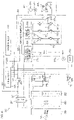
- FIGS. 6 and 7 are block diagrams of the marine vessel power supply system 50.
- the flywheel magnet 58 which is an example of the electric power generator, is connected to the rectifier/regulator 59.
- the DC/DC converter 60 and the main battery B1 are connected to the rectifier/regulator 59.
- the DC/DC converter 60 and the main battery B1 are connected in parallel.
- the motor driving battery B2 is connected to the DC/DC converter 60.
- the electric power generated by the flywheel magnet 58 is supplied to at least one of the DC/DC converter 60 and the main battery B1 via the rectifier/regulator 59.
- the DC/DC converter 60 increases the voltage of the DC electric power supplied from the rectifier/regulator 59 or the main battery B1, and supplies the DC electric power having the increased voltage to the motor driving battery B2.
- the marine vessel power supply system 50 includes a current sensor 71 to detect an electric current between the motor driving battery B2 and the DC/DC converter 60.
- the marine vessel power supply system 50 may include, instead of the current sensor 71, a current detection circuit to detect the electric current between the motor driving battery B2 and the DC/DC converter 60.
- the current sensor 71 is capable of detecting an electric current flowing through a wiring connecting the motor driving battery B2 and the DC/DC converter 60.
- the current sensor 71 detects the electric current flowing through the wiring between the positive electrode of the motor driving battery B2 and the DC/DC converter 60.
- the value of the electric current detected by the current sensor 71 is sent to the head ECU 55.
- the positive electrode of the motor driving battery B2 is connected to the inverter 61 via a main relay 73. Further, the positive electrode of the motor driving battery B2 is connected to the inverter 61 via a precharge relay 74 and an electric resistance 75. The precharge relay 74 and the electric resistance 75 are connected in parallel to the main relay 73. The negative electrode of the motor driving battery B2 is connected to the negative electrode of the inverter 61.
- the main relay 73 and the precharge relay 74 are normally open. The main relay 73 and the precharge relay 74 are opened and closed by the head ECU 55.
- the positive electrode of the main battery B1 is connected to the inverter 61 via the actuation switch 51 and a relay 72.
- the positive electrode of the main battery B1 is further connected to the water pump 68 via the actuation switch 51, the relay 72, and a relay 76.
- the inverter 61 and the water pump 68 are connected in parallel.
- the negative electrode of the main battery B1 is connected to the inverter 61 and the water pump 68.
- the relay 72 and the relay 76 are normally open.
- the relay 72 and the relay 76 are opened and closed by the engine ECU 56.
- the inverter 61 includes an inverter circuit 79 to convert the electric power between the DC electric power and the AC electric power, a smoothing capacitor 78 to reduce or prevent fluctuation of the DC voltage applied by the inverter circuit 79, and a drive circuit 85 which drives the inverter circuit 79.
- the inverter 61 further includes a microcomputer 86 to control the drive circuit 85, and a power supply circuit 87 to supply electric power supplied from a power source such as the main battery B1 to the microcomputer 86.
- the inverter circuit 79 includes a U-phase circuit 80u including a U-phase upper arm and a U-phase lower arm directly connected to each other, a V-phase circuit 80v including a V-phase upper arm and a V-phase lower arm directly connected to each other, and a W-phase circuit 80w including a W-phase upper arm and a W-phase lower arm directly connected to each other.
- the arms each include a switching element 81 such as IGBT (Insulated Gate Bipolar Transistor), and a freewheeling diode 82 connected in parallel to the switching element 81.
- the drive circuit 85 switches the respective switching elements 81 according to a command supplied from the microcomputer 86.
- the inverter 61 includes a positive electrode wiring 77p connected to the positive electrode of the motor driving battery B2, and a negative electrode wiring 77n connected to the negative electrode of the motor driving battery B2.
- the U-phase circuit 80u, the V-phase circuit 80v, and the W-phase circuit 80w are each connected to the positive electrode and the negative electrode of the motor driving battery B2 via the positive electrode wiring 77p and the negative electrode wiring 77n.
- the smoothing capacitor 78 is also connected to the positive electrode and the negative electrode of the motor driving battery B2 via the positive electrode wiring 77p and the negative electrode wiring 77n.
- the smoothing capacitor 78 is disposed between the inverter circuit 79 and the motor driving battery B2.
- the U-phase circuit 80u, the V-phase circuit 80v, the W-phase circuit 80w, and the smoothing capacitor 78 are connected in parallel.
- the inverter 61 further includes a U-phase wiring 77u connected to the U-phase coil 41u, a V-phase wiring 77v connected to the V-phase coil 41v, and a W-phase wiring 77w connected to the W-phase coil 41w.
- the U-phase wiring 77u is connected to the U-phase circuit 80u between the U-phase upper arm and the U-phase lower arm.
- the V-phase wiring 77v is connected to the V-phase circuit 80v between the V-phase upper arm and the V-phase lower arm.
- the W-phase wiring 77w is connected to the W-phase circuit 80w between the W-phase upper arm and the W-phase lower arm.
- the U-phase circuit 80u is connected to the U-phase coil 41u via the U-phase wiring 77u.
- the V-phase circuit 80v is connected to the V-phase coil 41v via the V-phase wiring 77v.
- the W-phase circuit 80w is connected to the W-phase coil 41w via the W-phase wiring
- the inverter 61 includes a voltage detection circuit 84 to detect a voltage between the motor driving battery B2 and the inverter circuit 79. More specifically, the voltage detection circuit 84 detects the voltage in the wirings 77p and 77n which connect the motor driving battery B2 to the inverter circuit 79 (more precisely, a voltage between the wirings 77p and 77n).
- the inverter 61 may include, instead of the voltage detection circuit 84, a voltage sensor to detect the voltage between the motor driving battery B2 and the inverter circuit 79.
- the voltage detection circuit 84 is connected between the positive electrode and the negative electrode of the motor driving battery B2 via the positive electrode wiring 77p and the negative electrode wiring 77n.
- the voltage detection circuit 84 detects a voltage between the opposite electrodes of the motor driving battery B2.
- the voltage detection circuit 84 is connected to the inverter circuit 79 in parallel.
- the value of the voltage detected by the voltage detection circuit 84 is sent to the microcomputer 86.
- the inverter 61 includes a plurality of current sensors 83 which each detect an electric current between the electric motor 41 and the inverter circuit 79.
- the inverter 61 may include, instead of the plurality of current sensors 83, a plurality of current detection circuits which each detect the electric current between the electric motor 41 and the inverter circuit 79.
- the current sensors 83 are provided in at least two of the U-phase wiring 77u, the V-phase wiring 77v, and the W-phase wiring 77w. In FIG. 7 , two current sensors 83 are respectively provided in the U-phase wiring 77u and the V-phase wiring 77v by way of example.
- the current sensors 83 are able to detect electric currents flowing through the wirings which connect the inverter circuit 79 to the electric motor 41.
- the values of the electric currents detected by the current sensors 83 are sent to the microcomputer 86.
- the microcomputer 86 includes a memory 86m which stores information such as a program, a CPU 86c (central processing unit) which performs computations and issues commands according to the program stored in the memory 86m, and an I/O port 86p (input/output port 86p) which acquires and outputs information and commands.
- the I/O port 86p is connected to the communication network N1.
- the microcomputer 86 communicates with the head ECU 55 and other electric devices via the I/O port 86p.
- the head ECU 55 includes a memory 55m which stores information such as a program, and a CPU 55c which performs computations and issues commands according to the program stored in the memory 55m.
- the head ECU 55 further includes an input interface 55i which acquires detection values of the sensors provided in the marine vessel 1, an output interface 55o which drives the electric devices provided in the marine vessel 1, and a communication interface 55co which communicates with the other devices via the communication network N1.
- the I/O port 86p of the inverter 61 is connected to the communication interface 55co via the communication network N1.
- the microcomputer 86 of the inverter 61 acquires the value of the voltage detected by the voltage detection circuit 84 of the inverter 61 through the I/O port 86p of the inverter 61, and transmits the acquired detected voltage value to the head ECU 55 through the I/O port 86p of the inverter 61. Similarly, the microcomputer 86 of the inverter 61 acquires the values of the electric currents detected by the current sensors 83 of the inverter 61 through the I/O port 86p of the inverter 61, and transmits the acquired detected current values to the head ECU 55 through the I/O port 86p of the inverter 61.
- FIG. 8 is a flowchart that shows a process flow to monitor the state of charge of the motor driving battery B2. In the following description, reference will be made to FIGS. 6 to 8 .
- Step S1 in FIG. 8 the electric power of the main battery B1 is supplied to the head ECU 55 and the engine ECU 56 to actuate the head ECU 55 and the engine ECU 56. Thereafter, the engine ECU 56 closes the relay 72 (see FIG. 6 ) to supply the electric power of the main battery B1 to the inverter 61. Thus, the inverter 61 is actuated.
- the head ECU 55 closes the precharge relay 74 (see FIG. 6 ) to supply the electric power of the motor driving battery B2 to the smoothing capacitor 78 of the inverter 61. Thus, electric charge is accumulated in the smoothing capacitor 78.
- the head ECU 55 opens the precharge relay 74, and closes the main relay 73 (see FIG. 6 ). With the main relay 73 closed, the smoothing capacitor 78 is charged until the voltage of the smoothing capacitor 78 is equal or substantially equal to the voltage of the motor driving battery B2. Thus, preparation to supply the electric power of the motor driving battery B2 to the electric motor 41 via the inverter 61 is completed.
- the voltage of the motor driving battery B2 (the voltage between the electrodes of the motor driving battery B2) observed when the electric current does not flow between the electric motor 41 and the inverter 61 corresponds to the OCV of the motor driving battery B2.
- the OCV of the motor driving battery B2 correlates with the SOC which indicates the remaining electric power amount of the motor driving battery B2.
- the SOC is expressed, for example, as a percentage from 0% to 100%. An SOC of 0% means that the remaining electric power amount is zero, and an SOC of 100% means that the remaining electric power amount is maximum.
- the voltage detection circuit 84 of the inverter 61 starts detecting the voltage after the actuation of the inverter 61.
- the microcomputer 86 of the inverter 61 continuously transmits the detected voltage value acquired from the voltage detection circuit 84 to the head ECU 55.
- the voltage detected by the voltage detection circuit 84 corresponds to the OCV of the motor driving battery B2.
- the inverter 61 (microcomputer 86) reads in the OCV of the motor driving battery B2 from the voltage detection circuit 84 (Step S2 in FIG. 8 ).
- the inverter 61 sends the OCV to the head ECU 55.
- the head ECU 55 When the head ECU 55 acquires the OCV of the motor driving battery B2 from the inverter 61 (Step S3 in FIG. 8 ), the head ECU 55 calculates an SOC estimate (an estimated SOC value) of the motor driving battery B2 based on the acquired OCV (Step S4 in FIG. 8 ). Further, the head ECU 55 permits the charging and the discharging of the motor driving battery B2 (Step S5 in FIG. 8 ).
- the head ECU 55 transmits to the inverter 61 a motor driving command to operate the electric motor 41 at a rotation speed in a rotation direction according to the position of the output adjustment handle 53.
- the inverter 61 supplies the electric power of the motor driving battery B2 to the electric motor 41 to rotate the electric motor 41 according to the motor driving command.
- the electric current flows between the electric motor 41 and the motor driving battery B2.
- the head ECU 55 starts monitoring the electric current flowing in and out of the motor driving battery B2 after permitting the charging and the discharging of the motor driving battery B2. Specifically, the head ECU 55 monitors, based on the detected electric current values acquired from the current sensors 83 and the current sensor 71, whether or not the electric current flowing in or out of the motor driving battery B2 is present (Step S6 in FIG. 8 ).
- Step S6 in FIG. 8 the head ECU 55 continues to monitor the electric current (Step S6 in FIG. 8 ) while permitting the charging and the discharging of the motor driving battery B2 (Step S5 in FIG. 8 ). If the electric current is present (YES in Step S6 in FIG. 8 ), the head ECU 55 updates the SOC estimate based on the detected electric current values acquired from the current sensors 83 and the current sensor 71 (Step S7 in FIG. 8 ). Thereafter, the head ECU 55 judges whether or not the SOC estimate falls within a range between an upper limit value and a lower limit value (Step S8 in FIG. 8 ).
- Step S6 the head ECU 55 continues to monitor the electric current (Step S6 in FIG. 8 ) while permitting the charging and the discharging of the motor driving battery B2 (Step S5 in FIG. 8 ).
- the head ECU 55 restricts the charging of the motor driving battery B2 (Step S10 in FIG. 8 ), and then continues to monitor the electric current (Step S12 in FIG. 8 ).
- the head ECU 55 restricts the discharging of the motor driving battery B2 (Step S10 in FIG. 8 ), and then continues to monitor the electric current (Step S12 in FIG. 8 ).
- Step S11 or Step S12 in FIG. 8 the head ECU 55 permits the charging and the discharging of the motor driving battery B2 (Step S5 in FIG. 8 ).
- the motor driving battery B2 is charged and discharged without any restriction.
- the head ECU 55 sends the command to the microcomputer 86 of the inverter 61
- the DC electric power of the motor driving battery B2 is converted to the AC electric power by the inverter circuit 79 of the inverter 61, and the AC electric power is supplied to the electric motor 41.
- the electric motor 41 is driven to rotate the propeller 23.
- the voltage detection circuit 84 of the inverter 61 which is an example of the voltage detector, detects the voltage in the wiring which connects the motor driving battery B2 to the inverter circuit 79.
- the OCV of the motor driving battery B2 which is detected by the voltage detection circuit 84 of the inverter 61, is sent to the head ECU 55 from the microcomputer 86 of the inverter 61.
- the head ECU 55 estimates the state of charge of the motor driving battery B2 based on the OCV of the motor driving battery B2 acquired from the inverter 61. Since the OCV of the motor driving battery B2 is thus determined by using the voltage detection circuit 84 and the microcomputer 86 of the inverter 61, there is no need to additionally provide the voltage sensor or the voltage detection circuit to detect the OCV of the motor driving battery B2. Further, there is no need to additionally provide the communication module for communications with the head ECU 55. Thus, the remaining electric power amount of the motor driving battery B2 is more accurately determined without the addition of the sensor and the like.
- the OCV of the motor driving battery B2 is detected by the voltage detection circuit 84 of the inverter 61, and is sent to the head ECU 55 from the microcomputer 86 of the inverter 61. Thereafter, the electric power of the motor driving battery B2 is supplied to the electric motor 41 via the inverter 61. After the electric power of the motor driving battery B2 is supplied to the electric motor 41 via the inverter 61, it is impossible to accurately measure the OCV of the motor driving battery B2 until the voltage of the motor driving battery B2 is stabilized.
- the value of the voltage detected by the voltage detection circuit 84 is acquired before the electric power of the motor driving battery B2 is supplied to the electric motor 41, such that the OCV is accurately and speedily acquired. This obviates the need for waiting for the stabilization of the voltage of the motor driving battery B2.
- the current sensors 83 which are examples of the current detector, are provided in addition to the voltage detection circuit 84 in the inverter 61.
- the OCV of the motor driving battery B2 is detected by the voltage detection circuit 84 of the inverter 61, and is sent to the head ECU 55 from the microcomputer 86 of the inverter 61.
- the SOC estimate of the motor driving battery B2 is determined.
- the electric current flowing between the motor driving battery B2 and the electric motor 41 is detected by the current sensors 83 of the inverter 61, and is sent to the head ECU 55 from the microcomputer 86 of the inverter 61.
- the head ECU 55 updates the SOC estimate based on the detected electric current values acquired from the microcomputer 86 of the inverter 61.
- the head ECU 55 updates the SOC estimate again based on the detected electric current values acquired from the microcomputer 86 of the inverter 61.
- the latest SOC estimate is determined in real time.
- the SOC estimate is updated by using the current sensors 83 and the microcomputer 86 of the inverter 61, obviating the need for additionally providing the current sensor or the current detection circuit and the need for additionally providing the communication module for communications with the head ECU 55.
- the OCV of the motor driving battery B2 is sent to the head ECU 55 from the microcomputer 86 of the inverter 61, and the head ECU 55 determines the SOC estimate of the motor driving battery B2.
- the head ECU 55 continuously updates the SOC estimate based on the electric current values detected by the current sensors 83 of the inverter 61 until the actuation switch 51 is thereafter turned off to stop the inverter 61 and the head ECU 55. At this time, the voltage value detected by the voltage detection circuit 84 of the inverter 61 is not taken into consideration.
- the SOC estimate is updated based on the integrated value of the electric current flowing in and out of the motor driving battery B2.
- the state of charge of the motor driving battery B2 is more accurately determined as compared with a case in which the SOC estimate is updated based on the voltage of the motor driving battery B2.
- the rectifier/regulator 59 converts the AC electric power generated by the flywheel magnet 58 (an example of the electric power generator) to the DC electric power.
- the DC/DC converter 60 increases the voltage of the DC electric power supplied from the rectifier/regulator 59, and supplies the DC electric power having the increased voltage to the motor driving battery B2. Therefore, even if the voltage of the DC electric power supplied from the rectifier/regulator 59 is lower than the rated voltage of the motor driving battery B2, the electric power generated by the flywheel magnet 58 is supplied to the motor driving battery B2 to charge the motor driving battery B2.
- the electric motor 41 and the inverter 61 are disposed outside the hull H1. Therefore, the electric motor 41 and the inverter 61 are disposed near the water surface around the marine vessel 1. The temperature is lower near the water surface than at a position spaced apart from the water surface. Therefore, the electric motor 41 and the inverter 61 are cooled with lower temperature air.
- the inverter 61 is disposed in the casing 9, and the inverter circuit 79, the voltage detection circuit 84, and the microcomputer 86 of the inverter 61 are disposed in the case 63 of the inverter 61.
- the inverter circuit 79 and the like are protected from solid matter such as dust and liquid such as water. Particularly, seawater or freshwater is present around the marine vessel 1 and, therefore, water splash and water droplets are liable to intrude into the marine vessel 1.
- the inverter circuit 79 and the like are protected from the water.
- the water pump 68 sucks in water from outside the marine vessel 1, and supplies the water to the cooling water channel 67.
- the water flowing in the cooling water channel 67 passes through the case 63 of the inverter 61 to cool the inverter 61. If the cooling liquid is circulated in the marine vessel 1 to cool the inverter 61, the temperature of the cooling liquid is liable to be gradually increased. In contrast, the temperature of the water outside the marine vessel 1 is generally constant irrespective of the period of use of the marine vessel 1. Therefore, the inverter 61 is cooled with the water having a stable temperature.
- the internal water pressure of the cooling water channel 67 is detected by the water pressure sensor 69 making it possible to detect whether or not the water is supplied into the cooling water channel 67.
- the water pressure sensor 69 is disposed in the case 63 of the inverter 61, and the inverter 61 is disposed in the casing 9, so that the water pressure sensor 69 is protected from solid matter such as dust and liquid such as water.
- both the electric motor 41 and the inverter 61 are mounted on the casing 9 of the outboard motor 8. It is, therefore, possible to complete the wiring between the electric motor 41 and the inverter 61, i.e., the three-phase wirings, at the casing 9.
- the three-phase wirings 77u, 77v, and 77W are substantially free from being affected by the steering of the outboard motor 8, thus contributing to a stable control of the electric motor 41. It is unnecessary to perform the wiring between the electric motor 41 and the inverter 61 when attaching the outboard motor 8 to the hull H1 because it is performed when assembling the outboard motor 8 in a factory.
- both the electric motor 41 and the inverter 61 may be mounted on the upper case 12 (see FIG. 4 ). With this arrangement, it is possible to complete the wiring between the electric motor 41 and the inverter 61, i.e., the three-phase wirings 77u, 77v, and 77w, at the upper case 12 (within the upper case 12 in this preferred embodiment).
- the wiring length is therefore further shortened and is further precisely defined. Additionally, it becomes easier to apply the same wiring length to different models of the outboard motor 8. This enables to reduce wiring variations between the electric motor 41 and the inverter 61, and the man-hours to adapt the control parameters in the system to the wiring length are also reduced accordingly.
- FIG. 9 is a schematic diagram showing an arrangement of another preferred embodiment of the present teaching.
- the same reference signs are used in the description of the present preferred embodiment for components corresponding to those in the above-described preferred embodiments.
- both the electric motor 41 and the inverter 61 are mounted on the casing 9 of the outboard motor 8. Specifically, both the electric motor 41 and the inverter 61 are mounted on the upper case 12. More specifically, the electric motor 41 is housed in the upper case 12.
- the case 63 of the inverter 61 is, on the other hand, attached to the upper case 12 such that at least a portion of the case 6 is exposed to the outside of the upper case 12. In the present preferred embodiment, not less than about half of the outer surface of the case 63, preferably not less than about 70% of the outer surface of the case 63, is disposed outside the upper case 12.
- the mounting height of the case 63 is designed such that at least a portion of the case 63, preferably an entire portion of the case 63, is disposed under a water level 90 when the marine vessel 1 is in use.
- the case 63 is disposed at a height that is determined such that at least a portion, preferably an entire portion, of the case 63 is under water around the outboard motor 8.
- both the electric motor 41 and the inverter 61 are mounted on the casing 9 of the outboard motor 8. It is therefore possible to complete the wiring between the electric motor 41 and the inverter 61, i.e., the three-phase wirings 77u, 77v, and 77w at the casing 9 so as to attain a stable control of the electric motor 41. Moreover, a precise wiring length between the electric motor 41 and the inverter 61 is attained, which also contributes to a stable control of the electric motor 41. Further, it is possible to reduce the wiring length, which reduces noise that arises when the electric motor 41 is energized, thus reducing the effects of such noise on the electronic components of the system as well as peripheral equipment.
- both the electric motor 41 and the inverter 61 are mounted on the upper case 12, which makes it possible to complete the wiring between the electric motor 41 and the inverter 61, i.e., three-phase wirings 77u, 77v, and 77w, in the upper case 12. It is, therefore, possible to further shorten the wiring and to more precisely define the wiring length. Moreover, it becomes easier to apply the same wiring length to different models of the outboard motor 8, thus reducing variations of the wirings between the electric motor 41 and the inverter 61, and man-hours to adapt the control parameters in the system to the wiring length are accordingly reduced.
- portions of the three-phase wirings 77u, 77v, and 77w are disposed outside the upper case 12 and outside the case 63 in the arrangement shown in FIG. 9 , this does not substantially affect the above-described technical advantages. It is possible to use a design in which entire portions of the three-phase cables 64u, 64v, and 64w are disposed within the upper case 12 and the case 63.
- Transom lengths may be different among different models of the outboard motor 8. It is still preferrable to use designs to maintain the relative positions of the electric motor 41 and the inverter 61 at the upper case 12 while attachments are introduced to cope with the different transom lengths. This makes it possible to reduce the variations of the wiring lengths, and, accordingly, to reduce man-hours to adapt the control parameters in the system to the wiring length.
- the case 63 of the inverter 61 is located at a height such that the case 63 is under water outside the upper case 12. This makes it possible to cool the inverter 61 with water around the outboard motor 8. It is, therefore, possible to omit a pump to send cooling water to cool the inverter 61, and to omit a cooling water channel from a pump to the inverter 61.
- the outboard motor 8 may be an outboard motor 8 of an electric type to rotate the propeller 23 by the electric motor 41 alone rather than the outboard motor 8 which is of a hybrid type to rotate the propeller 23 by at least one of the engine 14 and the electric motor 41.
- the propeller 23 may be attached to a portion of the propulsion system 2 other than the outboard motor 8.
- the propeller 23 may be attached to a side thruster (e.g., a bow thruster) which generates a propulsive force laterally of the hull H1.
- a side thruster e.g., a bow thruster
- At least one of the electric motor 41 and the inverter 61 may be disposed outside the casing 9 of the outboard motor 8. At least one of the electric motor 41 and the inverter 61 may be disposed inside the hull H1.
- the cooling water channel 67 which guides the water supplied to the inverter 61 does not have to extend through the case 63 of the inverter 61.
- a portion of the cooling water channel 67 may be disposed on the outer surface of the case 63.
- the cooling water channel 67 may be an endless flow channel through which the cooling liquid such as water is circulated in the marine vessel 1.
- the inverter 61 does not have to include the current sensors 83 which are examples of the current detector.
- the head ECU 55 may update the SOC estimate based on the value of the voltage detected by the voltage detection circuit 84 of the inverter 61 and acquired from the microcomputer 86 of the inverter 61.
- the electric power generated by the flywheel magnet 58 may be supplied to the motor driving battery B2 without increasing the voltage with the DC/DC converter 60. In this case, the DC/DC converter 60 may be eliminated.
- the motor driving battery B2 does not have to be charged with the electric power generated by the flywheel magnet 58.
Abstract
Description
- The present invention relates to a marine vessel power supply system and method which manages the power supply of a marine vessel, and a marine vessel including the same.
- In
US 2017/291672A1 , a marine vessel power supply system is disclosed. This system calculates the SOC (State of Charge) of a battery based on the OCV (Open Circuit Voltage) of the battery and the integrated value of an electric current flowing in and out of the battery. The battery SOC indicates the amount of electric power accumulated in the battery. The SOC is correlated with the OCV. The OCV is the voltage of the battery observed when the battery is in an equilibrium state with no electric current flowing between the battery and a load device. InUS 2017/291672A1 , the battery OCV is detected by an OCV sensor, and the detected OCV is inputted to a battery remaining power amount computing section for a propulsion system. A remote controller ECU determines the battery SOC based on the battery OCV acquired from the propulsion system battery remaining power amount computing section. - As described in
US 2017/291672A1 , the battery SOC can be more accurately determined through the calculation based on both the battery OCV and the integrated value of the electric current flowing in and out of the battery rather than based on the electric current integrated value alone. For the acquisition of the battery OCV, however, a sensor or a circuit for detecting the battery OCV is necessary, and a communication module for transmitting a detected OCV value to an electronic control unit for controlling the charging and the discharging of the battery is also necessary. - It is the object of the present invention to provide a marine vessel power supply system and method which manages the power supply of a marine vessel, and a marine vessel including the same, wherein the battery SOC value can be determined with high accuracy.
- According to the present invention said object is solved by marine vessel power supply system for a marine vessel having the features of
independent claim 1. Moreover, said object is solved by marine vessel according toclaim 6. Furthermore, said object is solved by marine vessel power supply method for a marine vessel having the features ofindependent claim 12. Preferred embodiments are laid down in the dependent claims. - In order to overcome the previously unrecognized and unsolved challenges described above, preferred embodiments of the present teaching provide marine vessel power supply systems for marine vessels each including an electric motor to rotate a propeller.
- A marine vessel power supply system according to a preferred embodiment of the present teaching includes an inverter to supply electric power to the electric motor, a battery to supply electric power to the inverter, and an electronic control unit configured or programmed to control the inverter. The inverter includes an inverter circuit to convert DC electric power supplied from the battery to AC electric power, a voltage detector to detect the voltage in a wiring between the battery and the inverter circuit, and a microcomputer configured or programmed to communicate with the electronic control unit and to control the inverter circuit according to a command supplied from the electronic control unit. The electronic control unit calculates an SOC estimate indicative of an estimated state-of-charge value of the battery based on a value of the voltage detected by the voltage detector and acquired from the microcomputer.
- With the above structural arrangement, when the electronic control unit sends the command to the microcomputer of the inverter, the DC electric power of the battery is converted to the AC electric power by the inverter circuit of the inverter, and the AC electric power is supplied to the electric motor. Thus, the electric motor is driven to rotate the propeller. The voltage detector of the inverter detects the voltage in the wiring between the battery and the inverter circuit. The OCV of the battery is able to be detected by the voltage detector of the inverter. Therefore, the microcomputer of the inverter is able to acquire the voltage value detected by the voltage detector as the battery OCV, and send the battery OCV to the electronic control unit. The electronic control unit is configured or programmed to estimate the state of charge of the battery based on the detected voltage value (particularly, the battery OCV) acquired from the inverter.
- Thus, the battery OCV is acquired by using the voltage detector and the microcomputer of the inverter, thus obviating the need to additionally provide the voltage sensor or the voltage detection circuit for the detection of the battery OCV. Further, there is no need to additionally provide a communication module for communications with the electronic control unit. Thus, the battery remaining power amount is accurately determined without the addition of the sensor and the like.
- The voltage detector may detect a voltage between opposite electrodes of the battery by detecting the voltage in the wiring. The voltage detector may detect a voltage between a positive electrode wiring and a negative electrode wiring of the inverter.
- In a preferred embodiment of the present teaching, the marine vessel power supply system may additionally include at least one of the following features.
- The marine vessel power supply system may further include an actuation switch operable by a user when a plurality of electric devices including the inverter and the electronic control unit are to be actuated. The electronic control unit may calculate the SOC estimate based on the detected voltage value acquired from the microcomputer before the electric power is supplied to the electric motor from the inverter after the plurality of electric devices are actuated by the operation of the actuation switch.
- With the above structural arrangement, when the inverter and the electronic control unit are actuated with the actuation switch turned on, the voltage value detected by the voltage detector of the inverter is sent to the electronic control unit from the microcomputer of the inverter. Thereafter, the electric power of the battery is supplied to the electric motor via the inverter. The voltage value detected before the electric power of the battery is supplied to the electric motor via the inverter corresponds to the battery OCV. After the electric power of the battery is supplied to the electric motor via the inverter, it is impossible to accurately measure the battery OCV until the voltage of the battery is stabilized. Therefore, the OCV is accurately and speedily determined by acquiring the voltage value detected by the voltage detector before the electric power of the battery is supplied to the electric motor. This obviates the need to wait until stabilization of the voltage of the battery.
- The inverter may further include a current detector to detect an electric current flowing between the battery and the electric motor. The electronic control unit may update the SOC estimate based on a value of the electric current detected by the current detector and acquired from the microcomputer after the SOC estimate is calculated based on the detected voltage value acquired from the microcomputer.
- With the above structural arrangement, the inverter includes the current detector in addition to the voltage detector. When the inverter and the electronic control unit are actuated by the operation of the actuation switch, the voltage value detected by the voltage detector of the inverter (corresponding to the battery OCV) is sent to the electronic control unit from the microcomputer of the inverter. Thus, the battery SOC estimate is determined. When the electric power of the battery is thereafter supplied to the electric motor via the inverter, the electric current flowing between the battery and the electric motor is detected by the current detector of the inverter, and the detected electric current value is sent to the electronic control unit from the microcomputer of the inverter. The electronic control unit updates the SOC estimate based on the detected electric current value acquired from the microcomputer of the inverter. When the battery is discharged or charged after the update of the SOC estimate, the electronic control unit updates the SOC estimate again based on the detected electric current value acquired from the microcomputer of the inverter. Thus, the latest SOC estimate is determined in real time. Further, the SOC estimate is updated by using the current detector and the microcomputer of the inverter, thus obviating the need for additionally providing the current sensor or the current detection circuit and obviating the need for additionally providing the communication module for communications with the electronic control unit.
- The current detector may be either a current detection circuit or a current sensor. The current detector may detect an electric current flowing through a wiring between the battery and the inverter circuit, or may detect an electric current flowing through a wiring between the electric motor and the inverter circuit. The current detector may detect an electric current flowing in the inverter circuit.
- The electronic control unit may continuously update the SOC estimate based on the detected electric current value acquired from the microcomputer without consideration of the detected voltage value acquired from the microcomputer until the actuation switch is turned off after the SOC estimate is calculated based on the detected voltage value acquired from the microcomputer.
- With the above structural arrangement, the actuation switch is turned off after the battery OCV is sent to the electronic control unit from the microcomputer of the inverter and the electronic control unit determines the battery SOC estimate. Then, the electronic control unit continuously updates the SOC estimate based on the electric current value detected by the current detector of the inverter until the inverter and the electronic control unit are stopped. At this time, the voltage value detected by the voltage detector of the inverter is not taken into consideration.
- As described above, it is impossible to accurately measure the battery OCV until the voltage of the battery is stabilized after the electric power of the battery is supplied to the electric motor via the inverter. Therefore, the state of charge of the battery is more accurately determined by updating the SOC estimate based on the integrated value of the electric current flowing in and out of the battery than by updating the SOC estimate based on the voltage of the battery.
- The marine vessel power supply system may further include an electric power generator, a rectifier/regulator to convert AC electric power generated by the electric power generator to DC electric power, and a DC/DC converter to increase the voltage of the DC electric power supplied from the rectifier/regulator and supply the DC electric power having the increased voltage to the battery.
- With the above structural arrangement, the rectifier/regulator converts the AC electric power generated by the electric power generator to the DC electric power. The DC/DC converter increases the voltage of the DC electric power supplied from the rectifier/regulator, and supplies the DC electric power having the increased voltage to the battery. Therefore, the electric power generated by the electric power generator is supplied to the battery to charge the battery even if the voltage of the DC electric power supplied from the rectifier/regulator is lower than the rated voltage of the battery.
- Another preferred embodiment of the present teaching provides a marine vessel, which includes a marine vessel power supply system according to a preferred embodiment of the present teaching described above, a propeller, an electric motor to receive electric power supplied thereto from the marine vessel power supply system to rotate the propeller, and a hull to travel on water due to the rotation of the propeller.
- With the above structural arrangement, when the electronic control unit sends the command to the microcomputer of the inverter, the DC electric power of the battery is converted to the AC electric power by the inverter circuit of the inverter, and the AC electric power is supplied to the electric motor. Thus, the electric motor and the propeller are rotated to propel the hull on the water. As described above, the remaining power amount of the battery is more accurately determined without the addition of the sensor and the like. This ensures more accurate determination of the battery remaining power amount, while preventing an increase in the number of the components of the marine vessel.
- In the present preferred embodiment, the marine vessel may additionally include at least one of the following features.
- The electric motor and the inverter may be disposed outside the hull.
- With the above structural arrangement, the electric motor and the inverter are disposed outside the hull. Therefore, the electric motor and the inverter are disposed near the water surface around the marine vessel. The temperature is lower near the water surface than at a position spaced apart from the water surface. Therefore, the electric motor and the inverter are able to be cooled with lower temperature air.
- The marine vessel may further include a casing to accommodate the inverter. The inverter may further include a case to accommodate the inverter circuit, the voltage detector, and the microcomputer.
- With the above structural arrangement, the inverter is disposed in the casing, and the inverter circuit, the voltage detector, and the microcomputer of the inverter are disposed in the case of the inverter. Thus, the inverter circuit and the like are protected from solid matter such as dust and liquid such as water. Particularly, water such as seawater or freshwater is present around the marine vessel and, therefore, water splash and water droplets are liable to intrude into the marine vessel. The inverter circuit and the like are protected from the water.
- The marine vessel may further include a cooling water channel extending through the case of the inverter, and a water pump to supply water from outside the marine vessel into the cooling water channel.
- With the above structural arrangement, the water pump sucks in the water from outside the marine vessel, and supplies the water into the cooling water channel. The water flowing through the cooling water channel passes through the case of the inverter to cool the inverter. If a cooling liquid is circulated in the marine vessel to cool the inverter, the temperature of the cooling liquid will be gradually increased. In contrast, the temperature of the water outside the marine vessel is generally constant irrespective of the period of use of the marine vessel. This makes it possible to cool the inverter with stable-temperature water.
- The marine vessel may further include a water pressure sensor provided in the case of the inverter to detect the internal water pressure of the cooling water channel.
- With the above structural arrangement, the internal water pressure of the cooling water channel is able to be detected by the water pressure sensor. Thus, whether or not the water is supplied into the cooling water channel is detected. Further, the water pressure sensor is disposed in the case of the inverter, and the inverter is disposed in the casing. This makes it possible to protect the water pressure sensor from solid matter such as dust and liquid such as water.
- The marine vessel may further include a cooling water channel which guides water for cooling the inverter, and a water pump to supply the water from outside the marine vessel into the cooling water channel.
- With the above structural arrangement, the water pump sucks in the water from outside the marine vessel, and supplies the water into the cooling water channel. The water flowing through the cooling water channel cools the inverter. If a cooling liquid is circulated in the marine vessel to cool the inverter, the temperature of the cooling liquid will be gradually increased. In contrast, the temperature of the water outside the marine vessel is generally constant irrespective of the period of use of the marine vessel. This makes it possible to cool the inverter with stable temperature water.
- A portion of the cooling water channel may be disposed in the inverter, or may be disposed on the outer surface of the inverter. In the former case, the inverter may define a portion of the cooling water channel. In this case, the water supplied to the cooling water channel by the water pump is brought into direct contact with the inverter to cool the inverter. This makes it possible to efficiently cool the inverter.
- The electric motor and the inverter may be mounted on a casing of an outboard motor that includes the propeller. With this structural arrangement, it is possible to complete the wiring (three-phase wirings, for example) between the electric motor and the inverter at the casing of the outboard motor. Therefore, the wiring is substantially free from being affected by the steering of the outboard motor, thus contributing to a stable control of the electric motor. Moreover, it is possible to perform the wiring between the electric motor and the inverter when the outboard motor is assembled in a factory, so that it is unnecessary to perform the wiring when the outboard motor is mounted on a hull. This makes it possible attain a precise wiring length between the electric motor and the inverter, thus attaining a stable control of the electric motor. Furthermore, a short wiring length is also attained so that it is possible to reduce noise that arises when the electric motor is energized thus reducing the effects of noise on the power supply system as well as peripheral equipment.
- The casing may include a lower case to which the propeller is attached and an upper case coupled to the lower case and arranged above the lower case. The electric motor and the inverter may be mounted on the upper case. With this structural arrangement, it is possible to complete the wiring (three-phase wirings, for example) between the electric motor and the inverter at the upper case. It is, therefore, possible to further shorten the wiring, and also to attain a more precise wiring length. Furthermore, it becomes easier to apply the same wiring length to different models of outboard motors. Variation in the wirings between the electric motor and the inverter are accordingly reduced, and man-hours to adapt the control parameters in the system to the wiring length are also reduced accordingly.
- A case of the inverter may be located at a height such that at least a portion of the case is under water outside the upper case. With this structural arrangement, it is possible to cool the inverter with water around the outboard motor. It is, therefore, possible to omit a pump that sends cooling water to cool the inverter, and to omit a cooling water channel from a pump to the inverter.
- The above and other elements, features, steps, characteristics and advantages of the present teaching will become more apparent from the following detailed description of the preferred embodiments with reference to the attached drawings.
-
-
FIG. 1 is a schematic diagram of a marine vessel according to a preferred embodiment of the present teaching. -
FIG. 2 is a sectional view that shows a vertical section of an outboard motor provided in the marine vessel. -
FIG. 3 is another sectional view that shows a vertical section of the outboard motor provided in the marine vessel. -
FIG. 4 is a schematic diagram of a marine vessel power supply system. -
FIG. 5 is a schematic diagram that shows an electric motor, an inverter, and a water pump. -
FIG. 6 is a block diagram of the marine vessel power supply system. -
FIG. 7 is another block diagram of the marine vessel power supply system. -
FIG. 8 is a flow chart that shows a process flow for monitoring the state of charge of a battery for driving the motor. -
FIG. 9 is a schematic diagram showing an arrangement of another preferred embodiment of the present teaching. -
FIG. 1 is a schematic diagram of amarine vessel 1 according to a preferred embodiment of the present teaching.FIGS. 2 and3 are sectional views each of which shows a vertical section of anoutboard motor 8 provided in themarine vessel 1. -
FIG. 1 illustrates a left side of theoutboard motor 8.FIG. 2 illustrates a state in which afirst dog clutch 21 is located at a neutral position, and asecond dog clutch 46 is located at an intermediate connection position.FIG. 3 illustrates a state in which thefirst dog clutch 21 is located at a forward drive position, and thesecond dog clutch 46 is located at a front connection position. InFIGS. 1 to 3 , arrows U and F indicate the upward direction and the forward direction, respectively, with respect to a hull H1. - As shown in
FIG. 1 , themarine vessel 1 includes a hull H1 which floats on a water surface, and apropulsion system 2 which propels the hull H1. Thepropulsion system 2 includes anoutboard motor 8 disposed behind the hull H1, and asuspension device 3 which attaches theoutboard motor 8 to the back side of the hull H1. Thepropulsion system 2 further includes a steering device which turns theoutboard motor 8 laterally of the hull H1, and a tilt device which turns theoutboard motor 8 vertically of the hull H1. - The
suspension device 3 includes aclamp bracket 4 attachable to the stern of the marine vessel, aswivel bracket 6 supported by theclamp bracket 4 via a laterally extendingtilt shaft 5, and asteering shaft 7 supported by theswivel bracket 6. Theswivel bracket 6 is pivotal about the laterally extendingtilt shaft 5 with respect to theclamp bracket 4. The steeringshaft 7 is rotatable about its vertical axis with respect to theswivel bracket 6. - The
outboard motor 8 is connected to an upper end and a lower end of thesteering shaft 7 via an upper mount and a lower mount, respectively. Theoutboard motor 8 is pivoted together with thesteering shaft 7 about thesteering shaft 7. Theoutboard motor 8 is pivotable about thesteering shaft 7 laterally of the hull H1, and is pivotable about thetilt shaft 5 vertically of the hull H1. - The
outboard motor 8 includes a first power train including anengine 14, and a second power train including anelectric motor 41. Theengine 14 and theelectric motor 41 are exemplary prime motors which rotate apropeller 23. The rotation of theengine 14 is transmitted to thepropeller 23 via apropeller shaft 22. Similarly, the rotation of theelectric motor 41 is transmitted to thepropeller 23 via thepropeller shaft 22. Therefore, thepropeller shaft 22 is shared by the first and second power trains. - The first power train defines a first transmission path P1 extending from the
engine 14 to thepropeller shaft 22. The second power train defines a second transmission path P2 extending from theelectric motor 41 to thepropeller shaft 22. InFIGS. 1 to 3 , the first transmission path P1 and the second transmission path P2 are indicated by bold one-dot-and-dash lines. The first transmission path P1 and the second transmission path P2 respectively extending from theengine 14 and theelectric motor 41 to thepropeller shaft 22 are separated from each other. The first transmission path P1 and the second transmission path P2 are parallel paths independent of each other. - The
outboard motor 8 includes acasing 9 in which the first and second power trains are accommodated. Thecasing 9 includes anengine cover 10 in which theengine 14 is accommodated, anexhaust guide 11 disposed below theengine 14, anupper case 12 disposed below theexhaust guide 11, and alower case 13 disposed below theupper case 12. Theengine cover 10 surrounds the entire periphery of theengine 14. Theengine 14 is disposed above theexhaust guide 11. Theelectric motor 41 is disposed at a lower position than theexhaust guide 11. Theelectric motor 41 is disposed within thelower case 13. Theelectric motor 41 may be disposed within the upper case 12 (seeFIG. 4 ). - The
engine 14 includes acrank shaft 15 which is rotated about a vertically extending rotation axis. The first power train includes adrive shaft 16 extending downward from theengine 14, and forward-reverse switching gears 17 which transmit the rotation of thedrive shaft 16 to thepropeller shaft 22. Thedrive shaft 16 is disposed in theupper case 12 and thelower case 13. The forward-reverse switching gears 17 and thepropeller shaft 22 are disposed in thelower case 13. Thepropeller shaft 22 extends anteroposteriorly in thelower case 13. Thepropeller 23 is disposed behind thelower case 13. Thepropeller 23 is attached to a rear end portion of thepropeller shaft 22. - The
engine 14 rotates thedrive shaft 16 in a predetermined rotation direction. Thepropeller 23 is rotated together with thepropeller shaft 22 in a forward direction or a reverse direction. The forward-reverse switching gears 17 are switched to one of a plurality of states including a forward drive state, a neutral state, and a reverse drive state. The forward drive state is such that the rotation in the forward direction is transmitted from the forward-reverse switching gears 17 to thepropeller shaft 22. The neutral state is such that the rotation is not transmitted from the forward-reverse switching gears 17 to thepropeller shaft 22. The reverse drive state is such that the rotation in the reverse direction is transmitted from the forward-reverse switching gears 17 to thepropeller shaft 22. - As shown in
FIGS. 2 and3 , the forward-reverse switching gears 17 include apinion 18 which is rotated together with thedrive shaft 16, afront gear 19 which is rotated by thepinion 18, and arear gear 20 which is rotated in a direction opposite from that of thefront gear 19 by thepinion 18. The forward-reverse switching gears 17 further include thefirst dog clutch 21, which is movable between a connection position at which thefirst dog clutch 21 is meshed with either one of thefront gear 19 and therear gear 20 and a disconnection position at which thefirst dog clutch 21 is spaced apart from both of thefront gear 19 and therear gear 20. Thepinion 18 functions as a first driving gear which is rotated by theengine 14. Thefront gear 19 and therear gear 20 cooperatively function as a first driven gear which is meshed with the first driving gear. - The
pinion 18, thefront gear 19, and therear gear 20 are each a bevel gear. Thepinion 18 is coaxial with thedrive shaft 16, and thefront gear 19 and therear gear 20 are coaxial with thepropeller shaft 22. Thefront gear 19 and therear gear 20 surround thepropeller shaft 22, and are supported by thelower case 13 in a rotatable manner. Thefront gear 19 and therear gear 20 are anteroposteriorly opposed to and spaced apart from each other. - The
first dog clutch 21 is disposed between thefront gear 19 and therear gear 20. Thefirst dog clutch 21 is located below thepinion 18. Thefirst dog clutch 21 is tubular, and surrounds thepropeller shaft 22. Thefirst dog clutch 21 is connected to thepropeller shaft 22 by an anteroposteriorly extending spline. Thefirst dog clutch 21 is anteroposteriorly movable with respect to thepropeller shaft 22, and is rotatable together with thepropeller shaft 22. - The
first dog clutch 21 includes a plurality offront projections 21f to be meshed with a plurality offront recesses 19f of thefront gear 19, and a plurality ofrear projections 21r to be meshed with a plurality ofrear recesses 20r of therear gear 20. Thefront projections 21f are aligned circumferentially of thefirst dog clutch 21, and each extend anteroposteriorly along axes of thepropeller shaft 22 and thefirst dog clutch 21. Similarly, therear projections 21r are aligned circumferentially of thefirst dog clutch 21, and each extend anteroposteriorly along the axes of thepropeller shaft 22 and thefirst dog clutch 21. Thefirst dog clutch 21, thefront recesses 19f, and therear recesses 20r cooperatively function as a first clutch that connects and disconnects the first transmission path P1. - The
first dog clutch 21 is located at one of the forward drive position (shown inFIG. 3 ), the neutral position (shown inFIG. 2 ), and a reverse drive position. The forward drive position is such that thefirst dog clutch 21 is meshed with thefront gear 19 to be rotated together with thefront gear 19. The reverse drive position is such that thefirst dog clutch 21 is meshed with therear gear 20 to be rotated together with therear gear 20. The neutral position is such that the rotation is not transmitted from the forward-reverse switching gears 17 to thepropeller shaft 22. The neutral position is a disconnection position such that the first transmission path P1 is disconnected. The forward drive position and the reverse drive position are connection positions such that the first transmission path P1 is not disconnected. - The
outboard motor 8 includes ashift device 31 which shifts the state of the forward-reverse switching gears 17. Theshift device 31 includes ashift slider 35 which is anteroposteriorly moved together with thefirst dog clutch 21, and aconnection pin 36 which connects thefirst dog clutch 21 to theshift slider 35. Theshift device 31 further includes apusher 34 which anteroposteriorly pushes theshift slider 35 to anteroposteriorly move thefirst dog clutch 21, a shift actuator 32 (seeFIG. 1 ) which generates power to anteroposteriorly move thepusher 34, and ashift rod 33 which transmits the power of theshift actuator 32 to thepusher 34. - As shown in
FIG. 1 , theshift actuator 32 is disposed in thecasing 9. Theshift actuator 32 is located at a lower position than theexhaust guide 11. Theshift actuator 32 moves up and down the shift rod 33 (seeFIGS. 2 and3 ) extending upward from thepusher 34, such that thepusher 34 is pivoted about a laterally extending rotation axis. Theshift actuator 32 may be an electric motor or an air cylinder, or any other device. Where theshift actuator 32 is the electric motor, the rotation of theshift actuator 32 may be converted into the vertical reciprocal movement of theshift rod 33 by a ball screw and a ball nut, for example. - As shown in
FIGS. 2 and3 , theshift slider 35 anteroposteriorly extends in thelower case 13. Theshift slider 35 is coaxial with thepropeller shaft 22. Theshift slider 35 is inserted in a center hole 22h of thepropeller shaft 22 extending rearward from a front end surface of thepropeller shaft 22. Theshift slider 35 is spline coupled to thepropeller shaft 22. Theshift slider 35 is anteroposteriorly movable with respect to thepropeller shaft 22, and is rotatable together with thepropeller shaft 22. Theshift slider 35 projects forward from the front end surface of thepropeller shaft 22. - The
shift slider 35 may be a single unitary member, or may include a plurality of members connected to each other. InFIGS. 2 and3 , theshift slider 35 is illustrated as including afront shaft 35s and arear tube 35t by way of example. Thefront shaft 35s and therear tube 35t are inserted in the center hole 22h of thepropeller shaft 22. Thefront shaft 35s is inserted in therear tube 35t. Thefront shaft 35s projects forward from the front end surface of thepropeller shaft 22. Thefront shaft 35s is spline coupled to thepropeller shaft 22. - The
pusher 34 is inserted in anannular groove 35g provided circumferentially of theshift slider 35 about a center axis of theshift slider 35. Theshift slider 35 includes an annular front opposedportion 35f and an annular rear opposedportion 35r respectively defining side surfaces of theannular groove 35g. The front opposedportion 35f is located forward of thepusher 34, and the rear opposedportion 35r is located rearward of thepusher 34. The front opposedportion 35f and the rear opposedportion 35r are opposed to thepusher 34 irrespective of the rotation angle of theshift slider 35. - When the
shift actuator 32 moves a lower end portion of thepusher 34 forward, the front opposedportion 35f of theshift slider 35 is pushed forward to move theshift slider 35 forward. When theshift actuator 32 moves the lower end portion of thepusher 34 rearward, the rear opposedportion 35r of theshift slider 35 is pushed rearward to move theshift slider 35 rearward. Thus, thefirst dog clutch 21 is located at one of the forward drive position, the neutral position, and the reverse drive position according to the movement amount of theshift slider 35. - The second power train includes an
intermediate shaft 42 which is rotated by theelectric motor 41, and asecond driving gear 43 which is rotated together with theintermediate shaft 42. The second power train further includes a second drivengear 44 which is rotated by thesecond driving gear 43, anintermediate ring 45 to be rotated together with the second drivengear 44, and theshift slider 35 surrounded by the second drivengear 44 and theintermediate ring 45. Theshift slider 35 is shared by the second power train and theshift device 31. - The
intermediate shaft 42 is disposed at a lower position than theelectric motor 41. Theintermediate shaft 42 extends vertically. Theintermediate shaft 42 is parallel or substantially parallel to thedrive shaft 16. Theintermediate shaft 42 is disposed forward of thedrive shaft 16. Theintermediate shaft 42 is connected to thesecond driving gear 43. Theintermediate shaft 42 and thesecond driving gear 43 are rotatable with respect to atubular shaft housing 47 fixed to thelower case 13. Theintermediate shaft 42 is disposed in theshaft housing 47. - The
second driving gear 43 and the second drivengear 44 are each a bevel gear. Thesecond driving gear 43 is located above theshift slider 35. The second drivengear 44 is coaxial with theshift slider 35, and surrounds theshift slider 35 in a radially spaced relation. The second drivengear 44 is meshed with thesecond driving gear 43. The second drivengear 44 is located forward of thefront gear 19. - The
intermediate ring 45 is coaxial with theshift slider 35, and surrounds theshift slider 35. InFIGS. 2 and3 , theintermediate ring 45 and the second drivengear 44 are illustrated as a single unitary member by way of example. Theintermediate ring 45 may be separate from the second drivengear 44 and fixed to the second drivengear 44. Theintermediate ring 45 is disposed forward of thefront gear 19. Theintermediate ring 45 is spaced forwardly from thepropeller shaft 22. Theintermediate ring 45 is supported rotatably by thelower case 13 via a bearing. - The second power train includes a second clutch that is switched between a connection state in which the
intermediate ring 45 is rotated together with theshift slider 35 and a disconnection state in which theintermediate ring 45 and theshift slider 35 are disconnected from each other. The second clutch includes thesecond dog clutch 46, which is anteroposteriorly movable between a connection position at which thesecond dog clutch 46 is meshed with theintermediate ring 45 and a disconnection position at which thesecond dog clutch 46 is spaced apart from theintermediate ring 45. InFIGS. 2 and3 , thesecond dog clutch 46 and theshift slider 35 are illustrated as a single unitary member. Thesecond dog clutch 46 may be separate from theshift slider 35 and fixed to theshift slider 35. - As shown in
FIGS. 2 and3 , thesecond dog clutch 46 includes a plurality ofprojections 46c to be meshed with a plurality ofrecesses 45c of theintermediate ring 45. Theprojections 46c are aligned circumferentially of thesecond dog clutch 46. Theprojections 46c project from theshift slider 35 radially outward of thesecond dog clutch 46. Therecesses 45c are recessed from an inner peripheral surface of theintermediate ring 45 radially outward of thesecond dog clutch 46. Therecesses 45c are aligned circumferentially of thesecond dog clutch 46. Theprojections 46c and therecesses 45c are located between theannular groove 35g and thefront gear 19 as seen in an anteroposterior direction. - The
second dog clutch 46 is located at one of a plurality of positions including a front connection position (shown inFIG. 3 ), an intermediate connection position (shown inFIG. 2 ), and a rear disconnection position. When thesecond dog clutch 46 is located at the front connection position or at the intermediate connection position, theprojections 46c are engaged with therecesses 45c. Thus, the second clutch is switched from the disconnection state to the connection state. In the connection state, the rotation is transmitted between theintermediate ring 45 and theshift slider 35 without slippage. In the disconnection state, the rotation is not transmitted between theintermediate ring 45 and theshift slider 35. - The
shift device 31 locates theshift slider 35 at one of a plurality of positions including a front position (shown inFIG. 3 ), an intermediate position (shown inFIG. 2 ), and a rear position. With theshift slider 35 located at the front position, thefirst dog clutch 21 is located at the forward drive position and thesecond dog clutch 46 is located at the front connection position. With theshift slider 35 located at the intermediate position, thefirst dog clutch 21 is located at the neutral position and thesecond dog clutch 46 is located at the intermediate connection position. With theshift slider 35 located at the rear position, thefirst dog clutch 21 is located at the reverse drive position and thesecond dog clutch 46 is located at the rear disconnection position. - Next, a marine vessel
power supply system 50 provided in themarine vessel 1 will be described. -
FIG. 4 is a schematic diagram of the marine vesselpower supply system 50. The marine vesselpower supply system 50 includes an output adjustment handle 53 which is operated to change the speed of themarine vessel 1 and to switch between the forward drive and the reverse drive of themarine vessel 1, and asteering wheel 52 which is operated to steer themarine vessel 1. The output adjustment handle 53 and thesteering wheel 52 are disposed in the hull H1. InFIG. 4 , anoutput adjustment lever 53L which is tilted anteroposteriorly is illustrated as the output adjustment handle 53 by way of example. The output adjustment handle 53 may be ajoystick 53j which functions as the output adjustment handle 53 and thesteering wheel 52, or may be a device other than theoutput adjustment lever 53L and thejoystick 53j. - The marine vessel
power supply system 50 includes an engine ECU 56 (Engine Electronic Control Unit) to control a plurality of electric devices such as theengine 14 provided in theoutboard motor 8, and a head ECU 55 (Head Electronic Control Unit) to control a plurality of electric devices such as theengine ECU 56 and theelectric motor 41 provided in themarine vessel 1. Theengine ECU 56 is disposed in theengine cover 10. Thehead ECU 55 is disposed in the hull H1. Thehead ECU 55 is an example of the electronic control unit. Theengine ECU 56 and thehead ECU 55 are connected to each other via a communication network N1 configured in conformity with communication standards such as CAN (Controller Area Network). Theengine ECU 56 and thehead ECU 55 send and receive information necessary for the control of theoutboard motor 8 and commands via the communication network N1. - The marine vessel
power supply system 50 includes aposition sensor 54 to detect the position of the output adjustment handle 53. Theposition sensor 54 is connected to thehead ECU 55. When thehead ECU 55 acquires handle position information indicative of the position of the output adjustment handle 53 from theposition sensor 54, thehead ECU 55 controls the shift actuator 32 (seeFIG. 1 ) to position thefirst dog clutch 21 and the second dog clutch 46 (seeFIGS. 2 and3 ) at positions according to the handle position information, and controls theengine 14 and theelectric motor 41 according to the handle position information. - When the
propeller 23 is to be rotated by theengine 14, thehead ECU 55 sends a shift control command to theengine ECU 56 in order to position thefirst dog clutch 21 at the forward drive position or the reverse drive position. Thehead ECU 55 further sends an engine control command to theengine ECU 56 in order to operate theengine 14 at a rotation speed in a rotation direction according to the position of the output adjustment handle 53. Thus, the rotation of theengine 14 is transmitted to thepropeller 23. - When the
propeller 23 is to be rotated by theelectric motor 41, thehead ECU 55 sends a shift control command to theengine ECU 56 in order to position thefirst dog clutch 21 at the neutral position and to position thesecond dog clutch 46 at the intermediate connection position. Thereafter, thehead ECU 55 rotates theelectric motor 41 at a rotation speed in a rotation direction according to the position of the output adjustment handle 53. Thus, the rotation of theelectric motor 41 is transmitted to thepropeller 23. - The marine vessel
power supply system 50 includes astarter motor 57 which starts up theengine 14. The marine vesselpower supply system 50 further includes anactuation switch 51 which is operated when the electric devices such as thestarter motor 57 provided in themarine vessel 1 are to be actuated, and a main battery B1 to supply electric power to the electric devices provided in themarine vessel 1. Thestarter motor 57 is disposed in theengine cover 10. The main battery B1 is disposed in the hull H1. When theactuation switch 51 is turned on, the electric power of the main battery B1 is supplied to thestarter motor 57 to rotate thestarter motor 57. Thus, theengine 14 is started up. - The marine vessel
power supply system 50 includes aflywheel magnet 58 which generates AC electric power according to the rotation of theengine 14, and a rectifier/regulator 59 to convert the AC electric power generated by theflywheel magnet 58 to DC electric power. Theflywheel magnet 58 and the rectifier/regulator 59 are disposed in theengine cover 10. Theflywheel magnet 58 is coaxial with the crank shaft 15 (seeFIG. 1 ). Theflywheel magnet 58 is a flywheel which doubles as the electric power generator. The electric power generated by theflywheel magnet 58 is supplied to the electric devices provided in themarine vessel 1 and to one or more batteries such as the main battery B1 provided in themarine vessel 1. - The marine vessel
power supply system 50 further includes a motor driving battery B2 which accumulates electric power to be supplied to theelectric motor 41, and aninverter 61 to supply the electric power of the motor driving battery B2 to theelectric motor 41. Theelectric motor 41 is driven by AC electric power supplied from theinverter 61. Theelectric motor 41 may be a three-phase AC motor, a brushless DC motor or other motor, as long as it is rotated by the AC electric power. The motor driving battery B2 is disposed in the hull H1. - The main battery B1 and the motor driving battery B2 are each a storage battery. The main battery B1 and the motor driving battery B2 may be a lead storage battery or other storage battery. The main battery B1 and the motor driving battery B2 each include a plurality of cells connected to each other in series and are repeatedly chargeable and dischargeable, and a battery box in which the plurality of cells are accommodated. In
FIG. 4 , the main battery B1 is illustrated as including a single battery, and the motor driving battery B2 is illustrated as including three batteries connected in series by way of example. Alternatively, the motor driving battery B2 may include a single battery. - The main battery B1 has a lower rated voltage than the motor driving battery B2. Alternatively, the rated voltage of the main battery B1 may be equal to the rated voltage of the motor driving battery B2, or may be higher than the rated voltage of the motor driving battery B2. Where the rated voltage of the main battery B1 is lower than the rated voltage of the motor driving battery B2, the marine vessel
power supply system 50 includes a DC/DC converter 60 which increases the voltage of the DC electric power. The DC/DC converter 60 is disposed in the hull H1. - The main battery B1 and the motor driving battery B2 are connected to the DC/
DC converter 60. Theflywheel magnet 58 is connected to the DC/DC converter 60 via the rectifier/regulator 59. The DC/DC converter 60 increases the voltage of the DC electric power supplied from at least one of the main battery B1 and the rectifier/regulator 59 to the rated voltage of the motor driving battery B2, and supplies the DC electric power having the increased voltage to the motor driving battery B2. Thus, the motor driving battery B2 is charged. -
FIG. 5 is a schematic diagram that illustrates theelectric motor 41, theinverter 61, and awater pump 68. - The
electric motor 41 includes a stator to which the electric power is supplied, and a rotor which is rotated due to the supply of the electric power to the stator. The stator includes aU-phase coil 41u, a V-phase coil 41v, and a W-phase coil 41w. Theelectric motor 41 further includes arotation angle sensor 41r to detect the rotation angle of theelectric motor 41, and atemperature sensor 41t to detect the temperature of theelectric motor 41. TheU-phase coil 41u, the V-phase coil 41v, and the W-phase coil 41w are connected to theinverter 61. Similarly, therotation angle sensor 41r and thetemperature sensor 41t are connected to theinverter 61. - The
inverter 61 includes amain body 62 electrically connected to a load device such as theelectric motor 41, and acase 63 defining a sealed space in which themain body 62 is accommodated. Thecase 63 is disposed in the casing 9 (seeFIG. 1 ) of theoutboard motor 8. Thecase 63 is located at a lower position than the exhaust guide 11 (seeFIG. 1 ). Themain body 62 is disposed in thecase 63. Themain body 62 is connected to a plurality of cables extending through thecase 63. The cables each include a covered wire including a conductor through which an electric current flows, and a tubular insulator covering the conductor. - The cables include a
U-phase cable 64u connecting theU-phase coil 41u to theinverter 61, a V-phase cable 64v connecting the V-phase coil 41v to theinverter 61, and a W-phase cable 64w connecting the W-phase coil 41w to theinverter 61. TheU-phase cable 64u, the V-phase cable 64v, and the W-phase cable 64w define the wirings 77u, 77v, and 77W (seeFIGs. 6 and7 ), i.e., three-phase wirings, that connect theinverter 61 and theelectric motor 41. The cables further include apositive electrode cable 64p which connects the positive electrode of the motor driving battery B2 to theinverter 61, and anegative electrode cable 64n which connects the negative electrode of the motor driving battery B2 to theinverter 61. - The cables further include a
control cable 65 which connects the communication network N1 to theinverter 61, and connects the main battery B1 to theinverter 61. Theinverter 61 is connected to thehead ECU 55 and theengine ECU 56 via thecontrol cable 65. The cables further include acontrol cable 66r which connects therotation angle sensor 41r to theinverter 61, and acontrol cable 66t which connects thetemperature sensor 41t to theinverter 61. Therotation angle sensor 41r and thetemperature sensor 41t are each connected to thehead ECU 55 and theengine ECU 56 via theinverter 61. - The
outboard motor 8 includes acooling water channel 67 which guides water taken in from outside themarine vessel 1 to theinverter 61, and awater pump 68 which sucks the water from outside themarine vessel 1 into the coolingwater channel 67. The coolingwater channel 67 and thewater pump 68 are disposed in the casing 9 (seeFIG. 1 ) of theoutboard motor 8. The coolingwater channel 67 extends through theinverter 61. Themain body 62 defines a portion of the coolingwater channel 67. The coolingwater channel 67 includes a water inlet port 67i through which the water is sucked in from outside themarine vessel 1, and a water outlet port 67o through which the water taken in through the water inlet port 67i is discharged to the outside of theoutboard motor 8. The water inlet port 67i and the water outlet port 67o each open to the outer surface of theoutboard motor 8. - The
water pump 68 is an electric pump which is operated due to the supply of the electric power. Thewater pump 68 may be a mechanical pump to be driven by the engine 14 (seeFIG. 1 ). Thewater pump 68, when being driven, generates a suction force to suck in the water from outside themarine vessel 1 through the water inlet port 67i of the coolingwater channel 67. Thus, the water flows into the coolingwater channel 67 from outside themarine vessel 1 through the water inlet port 67i of the coolingwater channel 67 to pass through theinverter 61. The water passing through theinverter 61 is drained to the outside of theoutboard motor 8 through the water outlet port 67o of the coolingwater channel 67. In this manner, theinverter 61 is cooled with the water taken in from outside themarine vessel 1. - The
outboard motor 8 includes, in addition to thecooling water channel 67 and thewater pump 68, awater pressure sensor 69 to detect the internal water pressure of the coolingwater channel 67. Thewater pressure sensor 69 is disposed outside themain body 62 in the sealed space of thecase 63. Thewater pressure sensor 69 may be disposed outside theinverter 61. Thewater pressure sensor 69 is connected to thehead ECU 55 and theengine ECU 56 via thecontrol cable 65. The internal water pressure of the coolingwater channel 67 detected by thewater pressure sensor 69 is sent to at least one of thehead ECU 55 and theengine ECU 56. -
FIGS. 6 and7 are block diagrams of the marine vesselpower supply system 50. - As shown in
FIG. 6 , theflywheel magnet 58, which is an example of the electric power generator, is connected to the rectifier/regulator 59. The DC/DC converter 60 and the main battery B1 are connected to the rectifier/regulator 59. The DC/DC converter 60 and the main battery B1 are connected in parallel. The motor driving battery B2 is connected to the DC/DC converter 60. - The electric power generated by the
flywheel magnet 58 is supplied to at least one of the DC/DC converter 60 and the main battery B1 via the rectifier/regulator 59. The DC/DC converter 60 increases the voltage of the DC electric power supplied from the rectifier/regulator 59 or the main battery B1, and supplies the DC electric power having the increased voltage to the motor driving battery B2. - The marine vessel
power supply system 50 includes acurrent sensor 71 to detect an electric current between the motor driving battery B2 and the DC/DC converter 60. The marine vesselpower supply system 50 may include, instead of thecurrent sensor 71, a current detection circuit to detect the electric current between the motor driving battery B2 and the DC/DC converter 60. Thecurrent sensor 71 is capable of detecting an electric current flowing through a wiring connecting the motor driving battery B2 and the DC/DC converter 60. Thecurrent sensor 71 detects the electric current flowing through the wiring between the positive electrode of the motor driving battery B2 and the DC/DC converter 60. The value of the electric current detected by thecurrent sensor 71 is sent to thehead ECU 55. - The positive electrode of the motor driving battery B2 is connected to the
inverter 61 via amain relay 73. Further, the positive electrode of the motor driving battery B2 is connected to theinverter 61 via aprecharge relay 74 and anelectric resistance 75. Theprecharge relay 74 and theelectric resistance 75 are connected in parallel to themain relay 73. The negative electrode of the motor driving battery B2 is connected to the negative electrode of theinverter 61. Themain relay 73 and theprecharge relay 74 are normally open. Themain relay 73 and theprecharge relay 74 are opened and closed by thehead ECU 55. - The positive electrode of the main battery B1 is connected to the
inverter 61 via theactuation switch 51 and arelay 72. The positive electrode of the main battery B1 is further connected to thewater pump 68 via theactuation switch 51, therelay 72, and arelay 76. Theinverter 61 and thewater pump 68 are connected in parallel. The negative electrode of the main battery B1 is connected to theinverter 61 and thewater pump 68. Therelay 72 and therelay 76 are normally open. Therelay 72 and therelay 76 are opened and closed by theengine ECU 56. - As shown in
FIG. 7 , theinverter 61 includes aninverter circuit 79 to convert the electric power between the DC electric power and the AC electric power, a smoothingcapacitor 78 to reduce or prevent fluctuation of the DC voltage applied by theinverter circuit 79, and adrive circuit 85 which drives theinverter circuit 79. Theinverter 61 further includes amicrocomputer 86 to control thedrive circuit 85, and apower supply circuit 87 to supply electric power supplied from a power source such as the main battery B1 to themicrocomputer 86. - The
inverter circuit 79 includes aU-phase circuit 80u including a U-phase upper arm and a U-phase lower arm directly connected to each other, a V-phase circuit 80v including a V-phase upper arm and a V-phase lower arm directly connected to each other, and a W-phase circuit 80w including a W-phase upper arm and a W-phase lower arm directly connected to each other. The arms each include a switchingelement 81 such as IGBT (Insulated Gate Bipolar Transistor), and a freewheelingdiode 82 connected in parallel to the switchingelement 81. Thedrive circuit 85 switches therespective switching elements 81 according to a command supplied from themicrocomputer 86. - The
inverter 61 includes apositive electrode wiring 77p connected to the positive electrode of the motor driving battery B2, and anegative electrode wiring 77n connected to the negative electrode of the motor driving battery B2. TheU-phase circuit 80u, the V-phase circuit 80v, and the W-phase circuit 80w are each connected to the positive electrode and the negative electrode of the motor driving battery B2 via thepositive electrode wiring 77p and thenegative electrode wiring 77n. The smoothingcapacitor 78 is also connected to the positive electrode and the negative electrode of the motor driving battery B2 via thepositive electrode wiring 77p and thenegative electrode wiring 77n. The smoothingcapacitor 78 is disposed between theinverter circuit 79 and the motor driving battery B2. TheU-phase circuit 80u, the V-phase circuit 80v, the W-phase circuit 80w, and the smoothingcapacitor 78 are connected in parallel. - The
inverter 61 further includes aU-phase wiring 77u connected to theU-phase coil 41u, a V-phase wiring 77v connected to the V-phase coil 41v, and a W-phase wiring 77w connected to the W-phase coil 41w. TheU-phase wiring 77u is connected to theU-phase circuit 80u between the U-phase upper arm and the U-phase lower arm. The V-phase wiring 77v is connected to the V-phase circuit 80v between the V-phase upper arm and the V-phase lower arm. The W-phase wiring 77w is connected to the W-phase circuit 80w between the W-phase upper arm and the W-phase lower arm. TheU-phase circuit 80u is connected to theU-phase coil 41u via theU-phase wiring 77u. The V-phase circuit 80v is connected to the V-phase coil 41v via the V-phase wiring 77v. The W-phase circuit 80w is connected to the W-phase coil 41w via the W-phase wiring 77w. - The
inverter 61 includes avoltage detection circuit 84 to detect a voltage between the motor driving battery B2 and theinverter circuit 79. More specifically, thevoltage detection circuit 84 detects the voltage in thewirings wirings inverter 61 may include, instead of thevoltage detection circuit 84, a voltage sensor to detect the voltage between the motor driving battery B2 and theinverter circuit 79. Thevoltage detection circuit 84 is connected between the positive electrode and the negative electrode of the motor driving battery B2 via thepositive electrode wiring 77p and thenegative electrode wiring 77n. Therefore, thevoltage detection circuit 84 detects a voltage between the opposite electrodes of the motor driving battery B2. Thevoltage detection circuit 84 is connected to theinverter circuit 79 in parallel. The value of the voltage detected by thevoltage detection circuit 84 is sent to themicrocomputer 86. - The
inverter 61 includes a plurality ofcurrent sensors 83 which each detect an electric current between theelectric motor 41 and theinverter circuit 79. Theinverter 61 may include, instead of the plurality ofcurrent sensors 83, a plurality of current detection circuits which each detect the electric current between theelectric motor 41 and theinverter circuit 79. Thecurrent sensors 83 are provided in at least two of theU-phase wiring 77u, the V-phase wiring 77v, and the W-phase wiring 77w. InFIG. 7 , twocurrent sensors 83 are respectively provided in theU-phase wiring 77u and the V-phase wiring 77v by way of example. Thecurrent sensors 83 are able to detect electric currents flowing through the wirings which connect theinverter circuit 79 to theelectric motor 41. The values of the electric currents detected by thecurrent sensors 83 are sent to themicrocomputer 86. - The
microcomputer 86 includes amemory 86m which stores information such as a program, aCPU 86c (central processing unit) which performs computations and issues commands according to the program stored in thememory 86m, and an I/O port 86p (input/output port 86p) which acquires and outputs information and commands. The I/O port 86p is connected to the communication network N1. Themicrocomputer 86 communicates with thehead ECU 55 and other electric devices via the I/O port 86p. - The
head ECU 55 includes amemory 55m which stores information such as a program, and aCPU 55c which performs computations and issues commands according to the program stored in thememory 55m. Thehead ECU 55 further includes aninput interface 55i which acquires detection values of the sensors provided in themarine vessel 1, an output interface 55o which drives the electric devices provided in themarine vessel 1, and a communication interface 55co which communicates with the other devices via the communication network N1. The I/O port 86p of theinverter 61 is connected to the communication interface 55co via the communication network N1. - The
microcomputer 86 of theinverter 61 acquires the value of the voltage detected by thevoltage detection circuit 84 of theinverter 61 through the I/O port 86p of theinverter 61, and transmits the acquired detected voltage value to thehead ECU 55 through the I/O port 86p of theinverter 61. Similarly, themicrocomputer 86 of theinverter 61 acquires the values of the electric currents detected by thecurrent sensors 83 of theinverter 61 through the I/O port 86p of theinverter 61, and transmits the acquired detected current values to thehead ECU 55 through the I/O port 86p of theinverter 61. -
FIG. 8 is a flowchart that shows a process flow to monitor the state of charge of the motor driving battery B2. In the following description, reference will be made toFIGS. 6 to 8 . - When the
actuation switch 51 is turned on (Step S1 inFIG. 8 ), the electric power of the main battery B1 is supplied to thehead ECU 55 and theengine ECU 56 to actuate thehead ECU 55 and theengine ECU 56. Thereafter, theengine ECU 56 closes the relay 72 (seeFIG. 6 ) to supply the electric power of the main battery B1 to theinverter 61. Thus, theinverter 61 is actuated. Thehead ECU 55 closes the precharge relay 74 (seeFIG. 6 ) to supply the electric power of the motor driving battery B2 to the smoothingcapacitor 78 of theinverter 61. Thus, electric charge is accumulated in the smoothingcapacitor 78. - After the electric charge is accumulated in the smoothing
capacitor 78, thehead ECU 55 opens theprecharge relay 74, and closes the main relay 73 (seeFIG. 6 ). With themain relay 73 closed, the smoothingcapacitor 78 is charged until the voltage of the smoothingcapacitor 78 is equal or substantially equal to the voltage of the motor driving battery B2. Thus, preparation to supply the electric power of the motor driving battery B2 to theelectric motor 41 via theinverter 61 is completed. - The voltage of the motor driving battery B2 (the voltage between the electrodes of the motor driving battery B2) observed when the electric current does not flow between the
electric motor 41 and theinverter 61 corresponds to the OCV of the motor driving battery B2. The OCV of the motor driving battery B2 correlates with the SOC which indicates the remaining electric power amount of the motor driving battery B2. The SOC is expressed, for example, as a percentage from 0% to 100%. An SOC of 0% means that the remaining electric power amount is zero, and an SOC of 100% means that the remaining electric power amount is maximum. - The
voltage detection circuit 84 of theinverter 61 starts detecting the voltage after the actuation of theinverter 61. Themicrocomputer 86 of theinverter 61 continuously transmits the detected voltage value acquired from thevoltage detection circuit 84 to thehead ECU 55. When the voltage of the smoothingcapacitor 78 is equal or substantially equal to the voltage of the motor driving battery B2, the voltage detected by thevoltage detection circuit 84 corresponds to the OCV of the motor driving battery B2. After themain relay 73 is closed, therefore, the inverter 61 (microcomputer 86) reads in the OCV of the motor driving battery B2 from the voltage detection circuit 84 (Step S2 inFIG. 8 ). Theinverter 61 sends the OCV to thehead ECU 55. - When the
head ECU 55 acquires the OCV of the motor driving battery B2 from the inverter 61 (Step S3 inFIG. 8 ), thehead ECU 55 calculates an SOC estimate (an estimated SOC value) of the motor driving battery B2 based on the acquired OCV (Step S4 inFIG. 8 ). Further, thehead ECU 55 permits the charging and the discharging of the motor driving battery B2 (Step S5 inFIG. 8 ). - When the output adjustment handle 53 (see
FIG. 4 ) is operated after the charging and the discharging of the motor driving battery B2 is permitted, as required, thehead ECU 55 transmits to the inverter 61 a motor driving command to operate theelectric motor 41 at a rotation speed in a rotation direction according to the position of the output adjustment handle 53. Theinverter 61 supplies the electric power of the motor driving battery B2 to theelectric motor 41 to rotate theelectric motor 41 according to the motor driving command. Thus, the electric current flows between theelectric motor 41 and the motor driving battery B2. When the electric power generated by theelectric motor 41 which doubles as the electric power generator is supplied to the motor driving battery B2 via theinverter 61, the electric current flows between theelectric motor 41 and the motor driving battery B2. - The
head ECU 55 starts monitoring the electric current flowing in and out of the motor driving battery B2 after permitting the charging and the discharging of the motor driving battery B2. Specifically, thehead ECU 55 monitors, based on the detected electric current values acquired from thecurrent sensors 83 and thecurrent sensor 71, whether or not the electric current flowing in or out of the motor driving battery B2 is present (Step S6 inFIG. 8 ). - If the electric current is not present (NO in Step S6 in
FIG. 8 ), thehead ECU 55 continues to monitor the electric current (Step S6 inFIG. 8 ) while permitting the charging and the discharging of the motor driving battery B2 (Step S5 inFIG. 8 ). If the electric current is present (YES in Step S6 inFIG. 8 ), thehead ECU 55 updates the SOC estimate based on the detected electric current values acquired from thecurrent sensors 83 and the current sensor 71 (Step S7 inFIG. 8 ). Thereafter, thehead ECU 55 judges whether or not the SOC estimate falls within a range between an upper limit value and a lower limit value (Step S8 inFIG. 8 ). - If the updated SOC estimate falls within the range between the upper limit value and the lower limit value (YES in Step S8 in
FIG. 8 ), thehead ECU 55 continues to monitor the electric current (Step S6 inFIG. 8 ) while permitting the charging and the discharging of the motor driving battery B2 (Step S5 inFIG. 8 ). If the updated SOC estimate is greater than the upper limit value (YES in Step S9 inFIG. 8 ), thehead ECU 55 restricts the charging of the motor driving battery B2 (Step S10 inFIG. 8 ), and then continues to monitor the electric current (Step S12 inFIG. 8 ). If the updated SOC estimate is smaller than the lower limit value (NO in Step S9 inFIG. 8 ), thehead ECU 55 restricts the discharging of the motor driving battery B2 (Step S10 inFIG. 8 ), and then continues to monitor the electric current (Step S12 inFIG. 8 ). - If the SOC estimate falls back within the range between the upper limit value and the lower limit value (YES in Step S8 in
FIG. 8 ) after the charging or the discharging of the motor driving battery B2 is restricted (Step S11 or Step S12 inFIG. 8 ), thehead ECU 55 permits the charging and the discharging of the motor driving battery B2 (Step S5 inFIG. 8 ). Thus, the motor driving battery B2 is charged and discharged without any restriction. - In a preferred embodiment of the present teaching, as described above, when the
head ECU 55 sends the command to themicrocomputer 86 of theinverter 61, the DC electric power of the motor driving battery B2 is converted to the AC electric power by theinverter circuit 79 of theinverter 61, and the AC electric power is supplied to theelectric motor 41. Thus, theelectric motor 41 is driven to rotate thepropeller 23. Thevoltage detection circuit 84 of theinverter 61, which is an example of the voltage detector, detects the voltage in the wiring which connects the motor driving battery B2 to theinverter circuit 79. The OCV of the motor driving battery B2, which is detected by thevoltage detection circuit 84 of theinverter 61, is sent to thehead ECU 55 from themicrocomputer 86 of theinverter 61. Thehead ECU 55 estimates the state of charge of the motor driving battery B2 based on the OCV of the motor driving battery B2 acquired from theinverter 61. Since the OCV of the motor driving battery B2 is thus determined by using thevoltage detection circuit 84 and themicrocomputer 86 of theinverter 61, there is no need to additionally provide the voltage sensor or the voltage detection circuit to detect the OCV of the motor driving battery B2. Further, there is no need to additionally provide the communication module for communications with thehead ECU 55. Thus, the remaining electric power amount of the motor driving battery B2 is more accurately determined without the addition of the sensor and the like. - In a preferred embodiment of the present teaching, when the
actuation switch 51 is turned on to actuate theinverter 61 and thehead ECU 55, the OCV of the motor driving battery B2 is detected by thevoltage detection circuit 84 of theinverter 61, and is sent to thehead ECU 55 from themicrocomputer 86 of theinverter 61. Thereafter, the electric power of the motor driving battery B2 is supplied to theelectric motor 41 via theinverter 61. After the electric power of the motor driving battery B2 is supplied to theelectric motor 41 via theinverter 61, it is impossible to accurately measure the OCV of the motor driving battery B2 until the voltage of the motor driving battery B2 is stabilized. Therefore, the value of the voltage detected by thevoltage detection circuit 84 is acquired before the electric power of the motor driving battery B2 is supplied to theelectric motor 41, such that the OCV is accurately and speedily acquired. This obviates the need for waiting for the stabilization of the voltage of the motor driving battery B2. - In a preferred embodiment of the present teaching, the
current sensors 83, which are examples of the current detector, are provided in addition to thevoltage detection circuit 84 in theinverter 61. When theinverter 61 and thehead ECU 55 are actuated by the operation of theactuation switch 51, the OCV of the motor driving battery B2 is detected by thevoltage detection circuit 84 of theinverter 61, and is sent to thehead ECU 55 from themicrocomputer 86 of theinverter 61. Thus, the SOC estimate of the motor driving battery B2 is determined. When the electric power of the motor driving battery B2 is thereafter supplied to theelectric motor 41 via theinverter 61, the electric current flowing between the motor driving battery B2 and theelectric motor 41 is detected by thecurrent sensors 83 of theinverter 61, and is sent to thehead ECU 55 from themicrocomputer 86 of theinverter 61. Thehead ECU 55 updates the SOC estimate based on the detected electric current values acquired from themicrocomputer 86 of theinverter 61. When the motor driving battery B2 is charged or discharged after the update of the SOC estimate, thehead ECU 55 updates the SOC estimate again based on the detected electric current values acquired from themicrocomputer 86 of theinverter 61. Thus, the latest SOC estimate is determined in real time. Further, the SOC estimate is updated by using thecurrent sensors 83 and themicrocomputer 86 of theinverter 61, obviating the need for additionally providing the current sensor or the current detection circuit and the need for additionally providing the communication module for communications with thehead ECU 55. - In a preferred embodiment of the present teaching, the OCV of the motor driving battery B2 is sent to the
head ECU 55 from themicrocomputer 86 of theinverter 61, and thehead ECU 55 determines the SOC estimate of the motor driving battery B2. Thehead ECU 55 continuously updates the SOC estimate based on the electric current values detected by thecurrent sensors 83 of theinverter 61 until theactuation switch 51 is thereafter turned off to stop theinverter 61 and thehead ECU 55. At this time, the voltage value detected by thevoltage detection circuit 84 of theinverter 61 is not taken into consideration. - After the electric power of the motor driving battery B2 is supplied to the
electric motor 41 via theinverter 61, as described above, it is impossible to accurately measure the OCV of the motor driving battery B2 until the voltage of the motor driving battery B2 is stabilized. Therefore, the SOC estimate is updated based on the integrated value of the electric current flowing in and out of the motor driving battery B2. Thus, the state of charge of the motor driving battery B2 is more accurately determined as compared with a case in which the SOC estimate is updated based on the voltage of the motor driving battery B2. - In a preferred embodiment of the present teaching, the rectifier/
regulator 59 converts the AC electric power generated by the flywheel magnet 58 (an example of the electric power generator) to the DC electric power. The DC/DC converter 60 increases the voltage of the DC electric power supplied from the rectifier/regulator 59, and supplies the DC electric power having the increased voltage to the motor driving battery B2. Therefore, even if the voltage of the DC electric power supplied from the rectifier/regulator 59 is lower than the rated voltage of the motor driving battery B2, the electric power generated by theflywheel magnet 58 is supplied to the motor driving battery B2 to charge the motor driving battery B2. - In a preferred embodiment of the present teaching, the
electric motor 41 and theinverter 61 are disposed outside the hull H1. Therefore, theelectric motor 41 and theinverter 61 are disposed near the water surface around themarine vessel 1. The temperature is lower near the water surface than at a position spaced apart from the water surface. Therefore, theelectric motor 41 and theinverter 61 are cooled with lower temperature air. - In a preferred embodiment of the present teaching, the
inverter 61 is disposed in thecasing 9, and theinverter circuit 79, thevoltage detection circuit 84, and themicrocomputer 86 of theinverter 61 are disposed in thecase 63 of theinverter 61. Thus, theinverter circuit 79 and the like are protected from solid matter such as dust and liquid such as water. Particularly, seawater or freshwater is present around themarine vessel 1 and, therefore, water splash and water droplets are liable to intrude into themarine vessel 1. Thus, theinverter circuit 79 and the like are protected from the water. - In a preferred embodiment of the present teaching, the
water pump 68 sucks in water from outside themarine vessel 1, and supplies the water to thecooling water channel 67. The water flowing in thecooling water channel 67 passes through thecase 63 of theinverter 61 to cool theinverter 61. If the cooling liquid is circulated in themarine vessel 1 to cool theinverter 61, the temperature of the cooling liquid is liable to be gradually increased. In contrast, the temperature of the water outside themarine vessel 1 is generally constant irrespective of the period of use of themarine vessel 1. Therefore, theinverter 61 is cooled with the water having a stable temperature. - In a preferred embodiment of the present teaching, the internal water pressure of the cooling
water channel 67 is detected by thewater pressure sensor 69 making it possible to detect whether or not the water is supplied into the coolingwater channel 67. Further, thewater pressure sensor 69 is disposed in thecase 63 of theinverter 61, and theinverter 61 is disposed in thecasing 9, so that thewater pressure sensor 69 is protected from solid matter such as dust and liquid such as water. - In a preferred embodiment of the present teaching, both the
electric motor 41 and theinverter 61 are mounted on thecasing 9 of theoutboard motor 8. It is, therefore, possible to complete the wiring between theelectric motor 41 and theinverter 61, i.e., the three-phase wirings, at thecasing 9. The three-phase wirings outboard motor 8, thus contributing to a stable control of theelectric motor 41. It is unnecessary to perform the wiring between theelectric motor 41 and theinverter 61 when attaching theoutboard motor 8 to the hull H1 because it is performed when assembling theoutboard motor 8 in a factory. This makes it possible to attain a precise wiring length between theelectric motor 41 and theinverter 61, thus attaining a stable control of theelectric motor 41. Further, it is also possible to attain a short wiring length, which reduces noise that arises when theelectric motor 41 is energized, thus reducing the effects of the noise on the electronic components of the system as well as the peripheral equipment. - As mentioned above, both the
electric motor 41 and theinverter 61 may be mounted on the upper case 12 (seeFIG. 4 ). With this arrangement, it is possible to complete the wiring between theelectric motor 41 and theinverter 61, i.e., the three-phase wirings upper case 12 in this preferred embodiment). The wiring length is therefore further shortened and is further precisely defined. Additionally, it becomes easier to apply the same wiring length to different models of theoutboard motor 8. This enables to reduce wiring variations between theelectric motor 41 and theinverter 61, and the man-hours to adapt the control parameters in the system to the wiring length are also reduced accordingly. -
FIG. 9 is a schematic diagram showing an arrangement of another preferred embodiment of the present teaching. The same reference signs are used in the description of the present preferred embodiment for components corresponding to those in the above-described preferred embodiments. - In the present preferred embodiment, both the
electric motor 41 and theinverter 61 are mounted on thecasing 9 of theoutboard motor 8. Specifically, both theelectric motor 41 and theinverter 61 are mounted on theupper case 12. More specifically, theelectric motor 41 is housed in theupper case 12. Thecase 63 of theinverter 61 is, on the other hand, attached to theupper case 12 such that at least a portion of thecase 6 is exposed to the outside of theupper case 12. In the present preferred embodiment, not less than about half of the outer surface of thecase 63, preferably not less than about 70% of the outer surface of thecase 63, is disposed outside theupper case 12. The mounting height of thecase 63 is designed such that at least a portion of thecase 63, preferably an entire portion of thecase 63, is disposed under awater level 90 when themarine vessel 1 is in use. In other words, thecase 63 is disposed at a height that is determined such that at least a portion, preferably an entire portion, of thecase 63 is under water around theoutboard motor 8. - Similarly to the above-described preferred embodiments, in the present preferred embodiment, both the
electric motor 41 and theinverter 61 are mounted on thecasing 9 of theoutboard motor 8. It is therefore possible to complete the wiring between theelectric motor 41 and theinverter 61, i.e., the three-phase wirings casing 9 so as to attain a stable control of theelectric motor 41. Moreover, a precise wiring length between theelectric motor 41 and theinverter 61 is attained, which also contributes to a stable control of theelectric motor 41. Further, it is possible to reduce the wiring length, which reduces noise that arises when theelectric motor 41 is energized, thus reducing the effects of such noise on the electronic components of the system as well as peripheral equipment. - In the present preferred embodiment, both the
electric motor 41 and theinverter 61 are mounted on theupper case 12, which makes it possible to complete the wiring between theelectric motor 41 and theinverter 61, i.e., three-phase wirings upper case 12. It is, therefore, possible to further shorten the wiring and to more precisely define the wiring length. Moreover, it becomes easier to apply the same wiring length to different models of theoutboard motor 8, thus reducing variations of the wirings between theelectric motor 41 and theinverter 61, and man-hours to adapt the control parameters in the system to the wiring length are accordingly reduced. Although portions of the three-phase wirings phase cables upper case 12 and outside thecase 63 in the arrangement shown inFIG. 9 , this does not substantially affect the above-described technical advantages. It is possible to use a design in which entire portions of the three-phase cables upper case 12 and thecase 63. - Transom lengths may be different among different models of the
outboard motor 8. It is still preferrable to use designs to maintain the relative positions of theelectric motor 41 and theinverter 61 at theupper case 12 while attachments are introduced to cope with the different transom lengths. This makes it possible to reduce the variations of the wiring lengths, and, accordingly, to reduce man-hours to adapt the control parameters in the system to the wiring length. - In the present preferred embodiment, the
case 63 of theinverter 61 is located at a height such that thecase 63 is under water outside theupper case 12. This makes it possible to cool theinverter 61 with water around theoutboard motor 8. It is, therefore, possible to omit a pump to send cooling water to cool theinverter 61, and to omit a cooling water channel from a pump to theinverter 61. - The present teaching is not limited to the preferred embodiments described above, but various modifications may be made.
- For example, the
outboard motor 8 may be anoutboard motor 8 of an electric type to rotate thepropeller 23 by theelectric motor 41 alone rather than theoutboard motor 8 which is of a hybrid type to rotate thepropeller 23 by at least one of theengine 14 and theelectric motor 41. - The
propeller 23 may be attached to a portion of thepropulsion system 2 other than theoutboard motor 8. For example, thepropeller 23 may be attached to a side thruster (e.g., a bow thruster) which generates a propulsive force laterally of the hull H1. - At least one of the
electric motor 41 and theinverter 61 may be disposed outside thecasing 9 of theoutboard motor 8. At least one of theelectric motor 41 and theinverter 61 may be disposed inside the hull H1. - The cooling
water channel 67 which guides the water supplied to theinverter 61 does not have to extend through thecase 63 of theinverter 61. In this case, a portion of the coolingwater channel 67 may be disposed on the outer surface of thecase 63. The coolingwater channel 67 may be an endless flow channel through which the cooling liquid such as water is circulated in themarine vessel 1. - If the current detection circuit or the current sensor to detect the electric current flowing between the motor driving battery B2 and the
electric motor 41 is provided, theinverter 61 does not have to include thecurrent sensors 83 which are examples of the current detector. - If the voltage of the motor driving battery B2 is stabilized in a certain period of time before the
actuation switch 51 is turned off after the calculation of the SOC estimate, thehead ECU 55 may update the SOC estimate based on the value of the voltage detected by thevoltage detection circuit 84 of theinverter 61 and acquired from themicrocomputer 86 of theinverter 61. - If the voltage of the DC electric power rectified by the rectifier/
regulator 59 equals the rated voltage of the motor driving battery B2, the electric power generated by theflywheel magnet 58 may be supplied to the motor driving battery B2 without increasing the voltage with the DC/DC converter 60. In this case, the DC/DC converter 60 may be eliminated. The motor driving battery B2 does not have to be charged with the electric power generated by theflywheel magnet 58. - Two or more of the arrangements described above may be used in combination.
Claims (15)
- A marine vessel power supply system (50) for a marine vessel (1) including an electric motor (41) configured to rotate a propeller (23), the marine vessel power supply system comprising:an inverter (61) configured to supply electric power to the electric motor (41);a battery (B2) configured to supply electric power to the inverter (61); andan electronic control unit (55) configured or programmed to control the inverter (61);whereinthe inverter (61) includes:an inverter circuit (79) configured to convert DC electric power supplied from the battery (B2) to AC electric power;a voltage detector (84) configured to detect a voltage value in a wiring between the battery (B2) and the inverter circuit (79); anda microcomputer (86) configured or programmed to communicate with the electronic control unit (55) and to control the inverter circuit (79) according to a command supplied from the electronic control unit (55); andthe electronic control unit (55) is configured or programmed to calculate an SOC estimate value indicative of an estimated state-of-charge value of the battery (B2) based on the voltage value detected by the voltage detector (84) and acquired from the microcomputer (86).
- The marine vessel power supply system (50) according to claim 1, further comprising:an actuation switch (51) configured to be operable by a user when a plurality of electric devices including the inverter (61) and the electronic control unit (55) are to be actuated; whereinthe electronic control unit (55) is configured or programmed to calculate the SOC estimate value based on the detected voltage value acquired from the microcomputer (86) before the electric power is supplied to the electric motor (41) from the inverter (61) after the plurality of electric devices are actuated by the operation of the actuation switch (51).
- The marine vessel power supply system (50) according to claim 2, wherein the inverter (61) further includes a current detector (83) configured to detect an electric current value flowing between the battery (B2) and the electric motor (41); and
the electronic control unit (55) is configured or programmed to update the SOC estimate value based on the electric current value detected by the current detector (83) and acquired from the microcomputer (86) after the SOC estimate value is calculated based on the detected voltage value acquired from the microcomputer (86). - The marine vessel power supply system (50) according to claim 3, wherein the electronic control unit (55) is configured or programmed to continuously update the SOC estimate value based on the detected electric current value acquired from the microcomputer (86) without consideration of the detected voltage value acquired from the microcomputer (86) until the actuation switch (51) is turned off after the SOC estimate value is calculated based on the detected voltage value acquired from the microcomputer (86).
- The marine vessel power supply system (50) according to any one of claims 1-4, further comprising:an electric power generator (58);a rectifier/regulator (59) configured to convert AC electric power generated by the electric power generator (58) to DC electric power; anda DC/DC converter (60) configured to receive the DC electric power from the rectifier/regulator (59), to increase a voltage of the DC electric power received from the rectifier/regulator (59), and to supply the DC electric power having the increased voltage to the battery (B2).
- A marine vessel (1) comprising:a marine vessel power supply system (50) according to any one of claims 1-5;a propeller (23);an electric motor (41) configured to receive electric power supplied thereto from the marine vessel power supply system (50) and to rotate the propeller (23); anda hull (H1) configured to travel on water due to the rotation of the propeller (23).
- The marine vessel (1) according to claim 6, wherein the electric motor (41) and the inverter (61) are disposed outside the hull (H1).
- The marine vessel (1) according to claim 6 or 7, further comprising:a casing (9) that accommodates the inverter (61); whereinthe inverter (61) further includes a case (63) that accommodates the inverter circuit (79), the voltage detector (84), and the microcomputer (86).
- The marine vessel (1) according to claim 8, further comprising:a cooling water channel (67) extending through the case (63) of the inverter (61); anda water pump (68) configured to supply water from outside the marine vessel (1) into the cooling water channel (67).
- The marine vessel (1) according to claim 9, further comprising a water pressure sensor (69) provided in the case (63) of the inverter (61) configured to detect an internal water pressure value of the cooling water channel (67).
- The marine vessel (1) according to any one of claims 6-8, further comprising:a cooling water channel (67) configured to guide water to cool the inverter (61); anda water pump (68) configured to supply the water from outside the marine vessel (1) into the cooling water channel (67).
- The marine vessel (1) according to claim 6 or 7, wherein the electric motor (41) and the inverter (61) are mounted on a casing (9) of an outboard motor (8) that includes the propeller (23).
- The marine vessel (1) according to claim 12, wherein the casing (9) includes a lower case (13) to which the propeller (23) is attached and an upper case (12) coupled to the lower case (13) and arranged above the lower case (13), and the electric motor (41) and the inverter (61) are mounted on the upper case (12).
- The marine vessel (1) according to claim 13, wherein a case (63) of the inverter (61) is located at a height such that at least a portion of the case (63) is under water outside the upper case (12).
- A marine vessel power supply method for a marine vessel (1) including an electric motor (41) configured to rotate a propeller (23), the marine vessel power supply method comprising:supplying electric power to the electric motor (41) by an inverter (61);supplying electric power to the inverter (61) by a battery (B2);controlling the inverter (61) andconverting DC electric power supplied from the battery (B2) to AC electric power;detecting a voltage value in a wiring between the battery (B2) and an inverter circuit (79) of the inverter (61); andcalculating an SOC estimate value indicative of an estimated state-of-charge value of the battery (B2) based on the detected voltage value.
Applications Claiming Priority (2)
| Application Number | Priority Date | Filing Date | Title |
|---|---|---|---|
| JP2020176751A JP2022067892A (en) | 2020-10-21 | 2020-10-21 | Power source system for vessel and vessel |
| EP21189093 | 2021-08-02 |
Publications (2)
| Publication Number | Publication Date |
|---|---|
| EP4011683A2 true EP4011683A2 (en) | 2022-06-15 |
| EP4011683A3 EP4011683A3 (en) | 2022-08-31 |
Family
ID=81536015
Family Applications (1)
| Application Number | Title | Priority Date | Filing Date |
|---|---|---|---|
| EP21203705.5A Pending EP4011683A3 (en) | 2020-10-21 | 2021-10-20 | Marine vessel power supply system, marine vessel and marine vessel power supply method |
Country Status (1)
| Country | Link |
|---|---|
| EP (1) | EP4011683A3 (en) |
Citations (1)
| Publication number | Priority date | Publication date | Assignee | Title |
|---|---|---|---|---|
| US20170291672A1 (en) | 2016-04-12 | 2017-10-12 | Yamaha Hatsudoki Kabushiki Kaisha | Vessel power supply system |
Family Cites Families (6)
| Publication number | Priority date | Publication date | Assignee | Title |
|---|---|---|---|---|
| FR2781755B1 (en) * | 1998-07-29 | 2000-09-29 | Alternatives En | ELECTRIC PROPULSION BOAT OR VESSEL |
| JP2004260905A (en) * | 2003-02-25 | 2004-09-16 | Yanmar Co Ltd | Hybrid system |
| KR100839381B1 (en) * | 2006-11-01 | 2008-06-20 | 삼성에스디아이 주식회사 | Battery management system and driving method thereof |
| JP6033155B2 (en) * | 2013-03-29 | 2016-11-30 | 日立オートモティブシステムズ株式会社 | Battery control device |
| WO2017011475A1 (en) * | 2015-07-13 | 2017-01-19 | Cedar Marine Propulsion, Inc. | Electric propulsion system for marine applications and method of use |
| EP3379278A1 (en) * | 2017-03-20 | 2018-09-26 | ABB Schweiz AG | Battery energy store |
-
2021
- 2021-10-20 EP EP21203705.5A patent/EP4011683A3/en active Pending
Patent Citations (1)
| Publication number | Priority date | Publication date | Assignee | Title |
|---|---|---|---|---|
| US20170291672A1 (en) | 2016-04-12 | 2017-10-12 | Yamaha Hatsudoki Kabushiki Kaisha | Vessel power supply system |
Also Published As
| Publication number | Publication date |
|---|---|
| EP4011683A3 (en) | 2022-08-31 |
Similar Documents
| Publication | Publication Date | Title |
|---|---|---|
| US11912388B2 (en) | Marine vessel power supply system, and marine vessel | |
| US8425268B2 (en) | Electric outboard motor | |
| US7195525B2 (en) | Outboard motor | |
| US10029775B2 (en) | Propulsion system for a person or a watercraft | |
| EP2559616B1 (en) | Electric outboard motor | |
| JP5521708B2 (en) | Electric outboard motor | |
| EP4140875A1 (en) | Electric marine propulsion system and control method | |
| JP2009143502A (en) | Vessel | |
| JP5367382B2 (en) | Ship power system | |
| EP4011683A2 (en) | Marine vessel power supply system, marine vessel and marine vessel power supply method | |
| JP4102220B2 (en) | Hybrid system | |
| EP4331972A1 (en) | Electric marine propulsion system and control method with voltage adaptation | |
| JP4193682B2 (en) | Electric outboard motor | |
| US20110244738A1 (en) | Electric outboard motor | |
| JP2011213241A (en) | Electric outboard motor | |
| EP3892530B1 (en) | Marine propulsion system and control method | |
| US20240158064A1 (en) | Electric marine propulsion system and power control method | |
| EP4369561A2 (en) | Electric marine propulsion systems and methods | |
| US20240157815A1 (en) | Electric marine propulsion system | |
| US20240017808A1 (en) | Assembly for providing electric power to a marine propulsion system | |
| US20240162672A1 (en) | Connectors for electric marine devices | |
| US20090075533A1 (en) | Watercraft | |
| US20240162729A1 (en) | Multiport battery | |
| JP6912895B2 (en) | Outboard motor | |
| EP4369560A2 (en) | Multiport battery |
Legal Events
| Date | Code | Title | Description |
|---|---|---|---|
| PUAI | Public reference made under article 153(3) epc to a published international application that has entered the european phase |
Free format text: ORIGINAL CODE: 0009012 |
|
| STAA | Information on the status of an ep patent application or granted ep patent |
Free format text: STATUS: THE APPLICATION HAS BEEN PUBLISHED |
|
| AK | Designated contracting states |
Kind code of ref document: A2 Designated state(s): AL AT BE BG CH CY CZ DE DK EE ES FI FR GB GR HR HU IE IS IT LI LT LU LV MC MK MT NL NO PL PT RO RS SE SI SK SM TR |
|
| PUAL | Search report despatched |
Free format text: ORIGINAL CODE: 0009013 |
|
| AK | Designated contracting states |
Kind code of ref document: A3 Designated state(s): AL AT BE BG CH CY CZ DE DK EE ES FI FR GB GR HR HU IE IS IT LI LT LU LV MC MK MT NL NO PL PT RO RS SE SI SK SM TR |
|
| RIC1 | Information provided on ipc code assigned before grant |
Ipc: B63H 21/20 20060101ALI20220725BHEP Ipc: B63H 20/28 20060101ALI20220725BHEP Ipc: B63H 20/14 20060101ALI20220725BHEP Ipc: B60L 50/16 20190101ALI20220725BHEP Ipc: B60L 50/15 20190101ALI20220725BHEP Ipc: B60L 58/12 20190101ALI20220725BHEP Ipc: B60L 50/61 20190101AFI20220725BHEP |
|
| STAA | Information on the status of an ep patent application or granted ep patent |
Free format text: STATUS: REQUEST FOR EXAMINATION WAS MADE |
|
| 17P | Request for examination filed |
Effective date: 20230109 |
|
| RBV | Designated contracting states (corrected) |
Designated state(s): AL AT BE BG CH CY CZ DE DK EE ES FI FR GB GR HR HU IE IS IT LI LT LU LV MC MK MT NL NO PL PT RO RS SE SI SK SM TR |