EP4011682A1 - Electric trolley - Google Patents
Electric trolley Download PDFInfo
- Publication number
- EP4011682A1 EP4011682A1 EP20849267.8A EP20849267A EP4011682A1 EP 4011682 A1 EP4011682 A1 EP 4011682A1 EP 20849267 A EP20849267 A EP 20849267A EP 4011682 A1 EP4011682 A1 EP 4011682A1
- Authority
- EP
- European Patent Office
- Prior art keywords
- driving
- electric trolley
- safety controller
- detector
- control
- Prior art date
- Legal status (The legal status is an assumption and is not a legal conclusion. Google has not performed a legal analysis and makes no representation as to the accuracy of the status listed.)
- Granted
Links
Images


Classifications
-
- B—PERFORMING OPERATIONS; TRANSPORTING
- B60—VEHICLES IN GENERAL
- B60L—PROPULSION OF ELECTRICALLY-PROPELLED VEHICLES; SUPPLYING ELECTRIC POWER FOR AUXILIARY EQUIPMENT OF ELECTRICALLY-PROPELLED VEHICLES; ELECTRODYNAMIC BRAKE SYSTEMS FOR VEHICLES IN GENERAL; MAGNETIC SUSPENSION OR LEVITATION FOR VEHICLES; MONITORING OPERATING VARIABLES OF ELECTRICALLY-PROPELLED VEHICLES; ELECTRIC SAFETY DEVICES FOR ELECTRICALLY-PROPELLED VEHICLES
- B60L15/00—Methods, circuits, or devices for controlling the traction-motor speed of electrically-propelled vehicles
- B60L15/20—Methods, circuits, or devices for controlling the traction-motor speed of electrically-propelled vehicles for control of the vehicle or its driving motor to achieve a desired performance, e.g. speed, torque, programmed variation of speed
-
- B—PERFORMING OPERATIONS; TRANSPORTING
- B60—VEHICLES IN GENERAL
- B60T—VEHICLE BRAKE CONTROL SYSTEMS OR PARTS THEREOF; BRAKE CONTROL SYSTEMS OR PARTS THEREOF, IN GENERAL; ARRANGEMENT OF BRAKING ELEMENTS ON VEHICLES IN GENERAL; PORTABLE DEVICES FOR PREVENTING UNWANTED MOVEMENT OF VEHICLES; VEHICLE MODIFICATIONS TO FACILITATE COOLING OF BRAKES
- B60T7/00—Brake-action initiating means
- B60T7/12—Brake-action initiating means for automatic initiation; for initiation not subject to will of driver or passenger
- B60T7/22—Brake-action initiating means for automatic initiation; for initiation not subject to will of driver or passenger initiated by contact of vehicle, e.g. bumper, with an external object, e.g. another vehicle, or by means of contactless obstacle detectors mounted on the vehicle
-
- A—HUMAN NECESSITIES
- A61—MEDICAL OR VETERINARY SCIENCE; HYGIENE
- A61G—TRANSPORT, PERSONAL CONVEYANCES, OR ACCOMMODATION SPECIALLY ADAPTED FOR PATIENTS OR DISABLED PERSONS; OPERATING TABLES OR CHAIRS; CHAIRS FOR DENTISTRY; FUNERAL DEVICES
- A61G5/00—Chairs or personal conveyances specially adapted for patients or disabled persons, e.g. wheelchairs
- A61G5/04—Chairs or personal conveyances specially adapted for patients or disabled persons, e.g. wheelchairs motor-driven
-
- A—HUMAN NECESSITIES
- A61—MEDICAL OR VETERINARY SCIENCE; HYGIENE
- A61G—TRANSPORT, PERSONAL CONVEYANCES, OR ACCOMMODATION SPECIALLY ADAPTED FOR PATIENTS OR DISABLED PERSONS; OPERATING TABLES OR CHAIRS; CHAIRS FOR DENTISTRY; FUNERAL DEVICES
- A61G5/00—Chairs or personal conveyances specially adapted for patients or disabled persons, e.g. wheelchairs
- A61G5/04—Chairs or personal conveyances specially adapted for patients or disabled persons, e.g. wheelchairs motor-driven
- A61G5/041—Chairs or personal conveyances specially adapted for patients or disabled persons, e.g. wheelchairs motor-driven having a specific drive-type
- A61G5/045—Rear wheel drive
-
- A—HUMAN NECESSITIES
- A61—MEDICAL OR VETERINARY SCIENCE; HYGIENE
- A61G—TRANSPORT, PERSONAL CONVEYANCES, OR ACCOMMODATION SPECIALLY ADAPTED FOR PATIENTS OR DISABLED PERSONS; OPERATING TABLES OR CHAIRS; CHAIRS FOR DENTISTRY; FUNERAL DEVICES
- A61G5/00—Chairs or personal conveyances specially adapted for patients or disabled persons, e.g. wheelchairs
- A61G5/10—Parts, details or accessories
- A61G5/1005—Wheelchairs having brakes
-
- B—PERFORMING OPERATIONS; TRANSPORTING
- B60—VEHICLES IN GENERAL
- B60L—PROPULSION OF ELECTRICALLY-PROPELLED VEHICLES; SUPPLYING ELECTRIC POWER FOR AUXILIARY EQUIPMENT OF ELECTRICALLY-PROPELLED VEHICLES; ELECTRODYNAMIC BRAKE SYSTEMS FOR VEHICLES IN GENERAL; MAGNETIC SUSPENSION OR LEVITATION FOR VEHICLES; MONITORING OPERATING VARIABLES OF ELECTRICALLY-PROPELLED VEHICLES; ELECTRIC SAFETY DEVICES FOR ELECTRICALLY-PROPELLED VEHICLES
- B60L15/00—Methods, circuits, or devices for controlling the traction-motor speed of electrically-propelled vehicles
- B60L15/20—Methods, circuits, or devices for controlling the traction-motor speed of electrically-propelled vehicles for control of the vehicle or its driving motor to achieve a desired performance, e.g. speed, torque, programmed variation of speed
- B60L15/2009—Methods, circuits, or devices for controlling the traction-motor speed of electrically-propelled vehicles for control of the vehicle or its driving motor to achieve a desired performance, e.g. speed, torque, programmed variation of speed for braking
-
- B—PERFORMING OPERATIONS; TRANSPORTING
- B60—VEHICLES IN GENERAL
- B60L—PROPULSION OF ELECTRICALLY-PROPELLED VEHICLES; SUPPLYING ELECTRIC POWER FOR AUXILIARY EQUIPMENT OF ELECTRICALLY-PROPELLED VEHICLES; ELECTRODYNAMIC BRAKE SYSTEMS FOR VEHICLES IN GENERAL; MAGNETIC SUSPENSION OR LEVITATION FOR VEHICLES; MONITORING OPERATING VARIABLES OF ELECTRICALLY-PROPELLED VEHICLES; ELECTRIC SAFETY DEVICES FOR ELECTRICALLY-PROPELLED VEHICLES
- B60L3/00—Electric devices on electrically-propelled vehicles for safety purposes; Monitoring operating variables, e.g. speed, deceleration or energy consumption
- B60L3/0007—Measures or means for preventing or attenuating collisions
- B60L3/0015—Prevention of collisions
-
- B—PERFORMING OPERATIONS; TRANSPORTING
- B60—VEHICLES IN GENERAL
- B60L—PROPULSION OF ELECTRICALLY-PROPELLED VEHICLES; SUPPLYING ELECTRIC POWER FOR AUXILIARY EQUIPMENT OF ELECTRICALLY-PROPELLED VEHICLES; ELECTRODYNAMIC BRAKE SYSTEMS FOR VEHICLES IN GENERAL; MAGNETIC SUSPENSION OR LEVITATION FOR VEHICLES; MONITORING OPERATING VARIABLES OF ELECTRICALLY-PROPELLED VEHICLES; ELECTRIC SAFETY DEVICES FOR ELECTRICALLY-PROPELLED VEHICLES
- B60L3/00—Electric devices on electrically-propelled vehicles for safety purposes; Monitoring operating variables, e.g. speed, deceleration or energy consumption
- B60L3/04—Cutting off the power supply under fault conditions
-
- B—PERFORMING OPERATIONS; TRANSPORTING
- B60—VEHICLES IN GENERAL
- B60T—VEHICLE BRAKE CONTROL SYSTEMS OR PARTS THEREOF; BRAKE CONTROL SYSTEMS OR PARTS THEREOF, IN GENERAL; ARRANGEMENT OF BRAKING ELEMENTS ON VEHICLES IN GENERAL; PORTABLE DEVICES FOR PREVENTING UNWANTED MOVEMENT OF VEHICLES; VEHICLE MODIFICATIONS TO FACILITATE COOLING OF BRAKES
- B60T7/00—Brake-action initiating means
- B60T7/12—Brake-action initiating means for automatic initiation; for initiation not subject to will of driver or passenger
-
- B—PERFORMING OPERATIONS; TRANSPORTING
- B60—VEHICLES IN GENERAL
- B60L—PROPULSION OF ELECTRICALLY-PROPELLED VEHICLES; SUPPLYING ELECTRIC POWER FOR AUXILIARY EQUIPMENT OF ELECTRICALLY-PROPELLED VEHICLES; ELECTRODYNAMIC BRAKE SYSTEMS FOR VEHICLES IN GENERAL; MAGNETIC SUSPENSION OR LEVITATION FOR VEHICLES; MONITORING OPERATING VARIABLES OF ELECTRICALLY-PROPELLED VEHICLES; ELECTRIC SAFETY DEVICES FOR ELECTRICALLY-PROPELLED VEHICLES
- B60L2200/00—Type of vehicles
- B60L2200/24—Personal mobility vehicles
-
- B—PERFORMING OPERATIONS; TRANSPORTING
- B60—VEHICLES IN GENERAL
- B60L—PROPULSION OF ELECTRICALLY-PROPELLED VEHICLES; SUPPLYING ELECTRIC POWER FOR AUXILIARY EQUIPMENT OF ELECTRICALLY-PROPELLED VEHICLES; ELECTRODYNAMIC BRAKE SYSTEMS FOR VEHICLES IN GENERAL; MAGNETIC SUSPENSION OR LEVITATION FOR VEHICLES; MONITORING OPERATING VARIABLES OF ELECTRICALLY-PROPELLED VEHICLES; ELECTRIC SAFETY DEVICES FOR ELECTRICALLY-PROPELLED VEHICLES
- B60L2200/00—Type of vehicles
- B60L2200/30—Trolleys
-
- B—PERFORMING OPERATIONS; TRANSPORTING
- B60—VEHICLES IN GENERAL
- B60L—PROPULSION OF ELECTRICALLY-PROPELLED VEHICLES; SUPPLYING ELECTRIC POWER FOR AUXILIARY EQUIPMENT OF ELECTRICALLY-PROPELLED VEHICLES; ELECTRODYNAMIC BRAKE SYSTEMS FOR VEHICLES IN GENERAL; MAGNETIC SUSPENSION OR LEVITATION FOR VEHICLES; MONITORING OPERATING VARIABLES OF ELECTRICALLY-PROPELLED VEHICLES; ELECTRIC SAFETY DEVICES FOR ELECTRICALLY-PROPELLED VEHICLES
- B60L2200/00—Type of vehicles
- B60L2200/34—Wheel chairs
-
- B—PERFORMING OPERATIONS; TRANSPORTING
- B60—VEHICLES IN GENERAL
- B60L—PROPULSION OF ELECTRICALLY-PROPELLED VEHICLES; SUPPLYING ELECTRIC POWER FOR AUXILIARY EQUIPMENT OF ELECTRICALLY-PROPELLED VEHICLES; ELECTRODYNAMIC BRAKE SYSTEMS FOR VEHICLES IN GENERAL; MAGNETIC SUSPENSION OR LEVITATION FOR VEHICLES; MONITORING OPERATING VARIABLES OF ELECTRICALLY-PROPELLED VEHICLES; ELECTRIC SAFETY DEVICES FOR ELECTRICALLY-PROPELLED VEHICLES
- B60L2220/00—Electrical machine types; Structures or applications thereof
- B60L2220/40—Electrical machine applications
- B60L2220/42—Electrical machine applications with use of more than one motor
-
- B—PERFORMING OPERATIONS; TRANSPORTING
- B60—VEHICLES IN GENERAL
- B60L—PROPULSION OF ELECTRICALLY-PROPELLED VEHICLES; SUPPLYING ELECTRIC POWER FOR AUXILIARY EQUIPMENT OF ELECTRICALLY-PROPELLED VEHICLES; ELECTRODYNAMIC BRAKE SYSTEMS FOR VEHICLES IN GENERAL; MAGNETIC SUSPENSION OR LEVITATION FOR VEHICLES; MONITORING OPERATING VARIABLES OF ELECTRICALLY-PROPELLED VEHICLES; ELECTRIC SAFETY DEVICES FOR ELECTRICALLY-PROPELLED VEHICLES
- B60L2220/00—Electrical machine types; Structures or applications thereof
- B60L2220/40—Electrical machine applications
- B60L2220/46—Wheel motors, i.e. motor connected to only one wheel
-
- B—PERFORMING OPERATIONS; TRANSPORTING
- B60—VEHICLES IN GENERAL
- B60L—PROPULSION OF ELECTRICALLY-PROPELLED VEHICLES; SUPPLYING ELECTRIC POWER FOR AUXILIARY EQUIPMENT OF ELECTRICALLY-PROPELLED VEHICLES; ELECTRODYNAMIC BRAKE SYSTEMS FOR VEHICLES IN GENERAL; MAGNETIC SUSPENSION OR LEVITATION FOR VEHICLES; MONITORING OPERATING VARIABLES OF ELECTRICALLY-PROPELLED VEHICLES; ELECTRIC SAFETY DEVICES FOR ELECTRICALLY-PROPELLED VEHICLES
- B60L2240/00—Control parameters of input or output; Target parameters
- B60L2240/10—Vehicle control parameters
- B60L2240/12—Speed
-
- B—PERFORMING OPERATIONS; TRANSPORTING
- B60—VEHICLES IN GENERAL
- B60L—PROPULSION OF ELECTRICALLY-PROPELLED VEHICLES; SUPPLYING ELECTRIC POWER FOR AUXILIARY EQUIPMENT OF ELECTRICALLY-PROPELLED VEHICLES; ELECTRODYNAMIC BRAKE SYSTEMS FOR VEHICLES IN GENERAL; MAGNETIC SUSPENSION OR LEVITATION FOR VEHICLES; MONITORING OPERATING VARIABLES OF ELECTRICALLY-PROPELLED VEHICLES; ELECTRIC SAFETY DEVICES FOR ELECTRICALLY-PROPELLED VEHICLES
- B60L2240/00—Control parameters of input or output; Target parameters
- B60L2240/40—Drive Train control parameters
- B60L2240/42—Drive Train control parameters related to electric machines
- B60L2240/421—Speed
-
- B—PERFORMING OPERATIONS; TRANSPORTING
- B60—VEHICLES IN GENERAL
- B60L—PROPULSION OF ELECTRICALLY-PROPELLED VEHICLES; SUPPLYING ELECTRIC POWER FOR AUXILIARY EQUIPMENT OF ELECTRICALLY-PROPELLED VEHICLES; ELECTRODYNAMIC BRAKE SYSTEMS FOR VEHICLES IN GENERAL; MAGNETIC SUSPENSION OR LEVITATION FOR VEHICLES; MONITORING OPERATING VARIABLES OF ELECTRICALLY-PROPELLED VEHICLES; ELECTRIC SAFETY DEVICES FOR ELECTRICALLY-PROPELLED VEHICLES
- B60L2240/00—Control parameters of input or output; Target parameters
- B60L2240/40—Drive Train control parameters
- B60L2240/46—Drive Train control parameters related to wheels
- B60L2240/461—Speed
-
- B—PERFORMING OPERATIONS; TRANSPORTING
- B60—VEHICLES IN GENERAL
- B60L—PROPULSION OF ELECTRICALLY-PROPELLED VEHICLES; SUPPLYING ELECTRIC POWER FOR AUXILIARY EQUIPMENT OF ELECTRICALLY-PROPELLED VEHICLES; ELECTRODYNAMIC BRAKE SYSTEMS FOR VEHICLES IN GENERAL; MAGNETIC SUSPENSION OR LEVITATION FOR VEHICLES; MONITORING OPERATING VARIABLES OF ELECTRICALLY-PROPELLED VEHICLES; ELECTRIC SAFETY DEVICES FOR ELECTRICALLY-PROPELLED VEHICLES
- B60L2240/00—Control parameters of input or output; Target parameters
- B60L2240/60—Navigation input
- B60L2240/64—Road conditions
- B60L2240/647—Surface situation of road, e.g. type of paving
-
- B—PERFORMING OPERATIONS; TRANSPORTING
- B60—VEHICLES IN GENERAL
- B60T—VEHICLE BRAKE CONTROL SYSTEMS OR PARTS THEREOF; BRAKE CONTROL SYSTEMS OR PARTS THEREOF, IN GENERAL; ARRANGEMENT OF BRAKING ELEMENTS ON VEHICLES IN GENERAL; PORTABLE DEVICES FOR PREVENTING UNWANTED MOVEMENT OF VEHICLES; VEHICLE MODIFICATIONS TO FACILITATE COOLING OF BRAKES
- B60T2201/00—Particular use of vehicle brake systems; Special systems using also the brakes; Special software modules within the brake system controller
- B60T2201/02—Active or adaptive cruise control system; Distance control
- B60T2201/022—Collision avoidance systems
-
- B—PERFORMING OPERATIONS; TRANSPORTING
- B60—VEHICLES IN GENERAL
- B60T—VEHICLE BRAKE CONTROL SYSTEMS OR PARTS THEREOF; BRAKE CONTROL SYSTEMS OR PARTS THEREOF, IN GENERAL; ARRANGEMENT OF BRAKING ELEMENTS ON VEHICLES IN GENERAL; PORTABLE DEVICES FOR PREVENTING UNWANTED MOVEMENT OF VEHICLES; VEHICLE MODIFICATIONS TO FACILITATE COOLING OF BRAKES
- B60T2201/00—Particular use of vehicle brake systems; Special systems using also the brakes; Special software modules within the brake system controller
- B60T2201/10—Automatic or semi-automatic parking aid systems
Definitions
- the present disclosure relates to an electric trolley having an automatic driving function and a steering support function.
- a human-boarding type electric trolley such as an electric wheelchair, having a function of not only travelling by being operated by a person but also detecting an obstacle by an obstacle detection sensor to stop the electric trolley.
- the electric trolley in a case where an abnormality occurs in the electric trolley, the electric trolley is stopped to prevent danger due to rough driving or collision, so that safety is ensured.
- interruption of a power supply circuit that supplies electric power to the electromotor is performed in a case where an abnormality occurs (PTL 1).
- an electric trolley that travels by controlling a motor fitted to a driving wheel of the electric trolley using a motor driver of the electric trolley, the electric trolley including a safety controller that determines whether or not to stop driving of the driving wheel, and a driving commander that outputs, to the motor driver, (i) an operation permission signal for permitting the motor to be operated and (ii) a control signal for controlling an operation of the motor, in which, when the safety controller determines to stop the driving of the driving wheel, the safety controller performs control to stop inputs of the operation permission signal and the control signal to the motor driver.
- An object of the present disclosure is to provide an electric trolley capable of mounting a configuration capable of stopping travel more reliably with a small size and a light weight.
- FIG. 1 is a schematic diagram of electric trolley 100, which is viewed from a side surface, according to a first exemplary embodiment of the present disclosure.
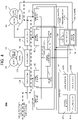
- FIG. 2 is a schematic diagram of stop control according to the first exemplary embodiment of the present disclosure.
- Electric trolley 100 includes main frame 101, training wheel 102, driving wheel 103, motor 104, brake 105, power supply 106, detector 107, and control box 108.
- Power supply 106 is a high voltage power supply, and supplies electric power to motor driver 109, motor 104, and brake 105, which will be described later. That is, as shown in FIG. 2 , power supply 106, motor driver 109, motor 104, and brake 105 belong to a high voltage power supply system.
- Main frame 101 is provided with seat 101A, footrest 101B, backrest 101C, and armrest 101D.
- Armrest 101D is provided with joystick 101E.
- a pair of training wheels 102 are installed on left and right sides at a front of electric trolley 100.
- a pair of driving wheels 103 are installed on left and right sides at a rear of electric trolley 100, and freely rotate around a rotation shaft (not shown) of motor 104.
- Motor 104 is provided for each of left and right driving wheels 103, and drives each of left and right driving wheels 103 independently.
- Brake 105 is provided for each of left and right driving wheels 103, and brakes each of left and right driving wheels 103.
- Power supply 106 supplies electric power to motor 104.
- Detector 107 includes at least one of obstacle detector 107A, area detector 107B, speed detector 107C, and step detector 107D which is an example of a road surface detector. Detector 107 is connected to driving commander 110 and safety controller 113, which will be described later.
- Obstacle detector 107A is disposed, for example, near a front of electric trolley 100. Obstacle detector 107A detects an obstacle by measuring a distance to a surrounding object, and outputs detected information to safety controller 113, which will be described later. Specifically, obstacle detector 107A is, for example, a laser sensor, which irradiates a periphery of electric trolley 100 with infrared laser light to scan a fan-shaped field centered on the sensor by approximately 270 degrees in a horizontal direction with a fine pitch such as every 0.36 degrees. Further, obstacle detector 107A detects the distance to the surrounding object based on time until reflected light is observed. A Time of Flight (TOF) sensor may be used as obstacle detector 107A.
- TOF Time of Flight
- obstacle detector 107A is realized by a simple configuration rather than the laser sensor.
- a stereo camera may be used as obstacle detector 107A.
- obstacle detector 107A can acquire color information and the like in addition to depth information. Therefore, it is possible to acquire more detailed information about a surrounding environment and an obstacle and it is possible to realize highly accurate operation control and accurate obstacle avoidance.
- Area detector 107B is disposed, for example, near the front of electric trolley 100. Area detector 107B detects area information of indicating whether a current travel area is a travelable area where the electric trolley can travel safely or a dangerous area, and outputs the detected area information to safety controller 113. Specifically, area detector 107B receives a signal from a signal transmitter fixed to a travel environment side, and detects an area of the current travel area.
- Speed detector 107C is connected to, for example, motor 104 or is disposed in the vicinity of motor 104. Speed detector 107C detects a travel speed of electric trolley 100 and outputs information of the detected speed to safety controller 113. Specifically, speed detector 107C calculates rotation speeds of motor 104 and driving wheel 103 by reading a rotation angle of motor 104, and detects the travel speed of electric trolley 100.
- Step detector 107D is disposed, for example, near the front of electric trolley 100. Step detector 107D detects a step on a travel road surface and outputs information of the detected step to safety controller 113. Specifically, step detector 107D is, for example, a laser sensor, which irradiates the periphery of electric trolley 100 with infrared laser light to scan the fan-shaped field centered on the sensor by approximately 270 degrees in a height direction with the fine pitch such as every 0.36 degrees. Further, step detector 107D detects a distance to the travel road surface based on the time until the reflected light is observed.
- step detector 107D it is determined that a step exists on the travel road surface based on a predetermined condition such as a case where the distance to the travel road surface is not continuous or a case where the distance is significantly changed.
- the TOF sensor may be used as step detector 107D.
- step detector 107D is realized by a simpler configuration than the laser sensor.
- a stereo camera may be used as step detector 107D.
- step detector 107D can acquire color information and the like in addition to the depth information. Therefore, it is possible to acquire more detailed information about the step and it is possible to realize highly accurate operation control and accurate step avoidance.
- a configuration of a sensor and the like for detecting state information may be grouped with a configuration of a processor and the like for converting the detected state information into information to be output to safety controller 113 or for calculating the state information.
- the information detected by detector 107 may be further used for improving travel property of electric trolley 100 such as obstacle avoidance and path generation.
- driving commander 110 which will be described later, performs control to improve the travel property based on the information detected by detector 107. That is, it is desirable that a configuration in which the detected information by detector 107 is processed and output for improving the travel property is separately configured from a configuration in which the detected information is processed and output for improving safety. As a result, even in a case where a failure or defect occurs in any of the configurations and an abnormality occurs in the control, the operation of electric trolley 100 can be stopped by the other configuration.
- safety controller 113 performs control to stop the driving of electric trolley 100 based on the information detected by detector 107, as will be described later.
- driving commander 110 performs control to stop the driving of electric trolley 100 based on the operation amount of joystick 101E.
- Control box 108 is provided with motor driver 109, driving commander 110, operation blocker 111, control blocker 112, and safety controller 113.
- motor driver 109 belongs to the high voltage power supply system, but driving commander 110, operation blocker 111, control blocker 112, and safety controller 113 belong to a low voltage power supply system.
- the electric power is supplied from power supply 106 to driving commander 110, safety controller 113, and the like, which belong to the low voltage power supply system via, for example, a step-down transformer.
- control box 108, power supply 106, and the like are provided separately from seat 101A, backrest 101C, and the like in order to reduce discomfort to a passenger due to exhausted heat.
- control box 108, power supply 106, and the like are provided under electric trolley 100 in order to reduce instability because a center of gravity of electric trolley 100 becomes high.
- motor driver 109 controls the rotation of each motor 104 to operate motor 104.
- Motor driver 109 is in a state in which motor 104 can be controlled by inputting an operation permission signal from driving commander 110. Thereafter, motor driver 109 controls rotation of motor 104 so as to operate motor 104 according to a control signal input from driving commander 110. That is, motor driver 109 does not control motor 104 unless the operation permission signal is input from driving commander 110. For example, motor driver 109 does not control motor 104 in a case where the control signal is input from driving commander 110 in a state in which the operation permission signal is not input from driving commander 110.
- driving commander 110 In a case where driving commander 110 can give a command to motor driver 109, driving commander 110 outputs the operation permission signal to motor driver 109. Thereafter, in a case where the operation amount of joystick 101E is input, driving commander 110 determines a rotation speed of motor 104 based on the operation amount of joystick 101E, and outputs the control signal to motor driver 109.
- the control signal includes a control value based on the rotation speed of motor 104.
- driving commander 110 can give the command to motor driver 109.
- driving commander 110 may transmit the operation permission signal. That is, driving commander 110 transmits the operation permission signal in a case where the travel control becomes possible.
- driving commander 110 may stop transmission of the operation permission signal.
- driving commander 110 may transmit the operation permission signal in a case where a failure of detector 107, an abnormality of safety controller 113, or the like is not generated and electric trolley 100 does not have a problem on travel.
- the abnormality indicates, for example, a state in which power is not supplied to detector 107, a state in which communication between communication configurations cannot be performed, and the like.
- Driving commander 110 confirms whether or not the states occur by inputting the detected information from detector 107 or performing communication. It is preferable that driving commander 110 transmits the operation permission signal in a case where the states do not occur. In addition, driving commander 110 may transmit the operation permission signal in a case where it is determined that there is no problem on the travel in the surrounding environment of electric trolley 100 based on the detected information by detector 107. In addition, driving commander 110 may transmit the operation permission signal in a case where an instruction is input by a manual operation by a user.
- the transmission of the operation permission signal may be performed in a case where a brake device included in electric trolley 100 is released by a passenger, or an instruction of the user to operate electric trolley 100 may be input using a terminal or the like capable of communicating with electric trolley 100.
- driving commander 110 can give the command to motor driver 109 may be automatically determined by driving commander 110 or may be input manually.
- Driving commander 110 may continuously transmit the operation permission signal while determining to be capable of giving the command to motor driver 109, and may stop transmission of the operation permission signal in a case of not being capable of giving the command to motor driver 109.
- operation commander 10 transmits the operation permission signal in addition to the control signal.
- the erroneously transmitted control signal can be invalidated by not transmitting the operation permission signal. Therefore, safety can be improved.
- joystick 101E may have another form such as a handle or a remote controller.
- operation blocker 111 blocks the operation permission signal input from driving commander 110 to motor driver 109. In a case where the operation blocking signal is not input from safety controller 113, operation blocker 111 does not block the operation permission signal output from driving commander 110 to motor driver 109.
- Operation blocker 111 is a switching element, and is configured with, for example, a tri-state buffer.
- a configuration is used in which operation blocker 111 is provided for each motor driver 109 one by one, but the present disclosure is not limited thereto, and the operation permission signal input from driving commander 110 to each motor driver 109 may be blocked by one operation blocker 111.
- operation blocker 111 is provided for each motor driver 109 one by one, it is possible to cause operation blocker 111 to easily correspond to specification of each motor driver 109 in a case where motor driver 109 is replaced according to driving wheel 103 or motor 104, in a case where the number of motor drivers 109 is increased or decreased, and the like.
- control blocker 112 blocks the control signal input from driving commander 110 to motor driver 109. In the case where the control blocking signal is not input from safety controller 113, control blocker 112 does not block the control signal output from driving commander 110 to motor driver 109.
- Control blocker 112 is a switching element, and is configured with, for example, a tri-state buffer.
- a configuration is used in which control blocker 112 is provided for each motor driver 109 one by one, but the present disclosure is not limited thereto, and the operation permission signal input from driving commander 110 to each motor driver 109 may be blocked by one control blocker 112.
- control blocker 112 is provided for each motor driver 109 one by one, it is possible to cause control blocker 112 to easily correspond to the specification of each motor driver 109 in the case where motor driver 109 is replaced according to driving wheel 103 or motor 104, in the case where the number of motor drivers 109 is increased or decreased, and the like.
- Safety controller 113 determines whether or not it is necessary to stop the driving of electric trolley 100 based on the information input from detector 107. In a case where safety controller 113 determines that it is necessary to stop the driving of electric trolley 100, safety controller 113 outputs the operation blocking signal to operation blocker 111 and the control blocking signal to control blocker 112, respectively, through paths independent of each other, and stops driving of motor 104. That is, safety controller 113 includes at least one of a connector for inputting the operation blocking signal to operation blocker 111 and a connector for inputting the control blocking signal to control blocker 112.
- Safety controller 113 stops an operation of motor driver 109 by controlling the output of the operation permission signal and an operation of motor 104 independently of each other.
- safety controller 113 stops the control of motor 104 by motor driver 109 by controlling operation blocker 111 and control blocker 112 independently of each other.
- two circuits exist for inputting signals for stopping the driving of motor 104, so that the driving of motor 104 can be stopped more reliably.
- safety controller 113 may brake driving wheel 103 by operating brake 105 by inputting a brake signal to brake 105 in a case where the speed is not sufficiently reduced at the same time or after a certain time elapses.
- the case where the speed is not sufficiently decelerated indicates, for example, a case where the speed is not zero.
- safety controller 113 determines whether or not it is necessary to stop the driving of electric trolley 100, for example, as follows.
- safety controller 113 determines that it is necessary to stop the driving of electric trolley 100. At this time, specifically, a situation is conceivable in which motor driver 109 is not normally controlled due to an abnormality or the like in driving commander 110, so that there is a problem in that rough driving or collision occurs.
- safety controller 113 determines that it is necessary to stop the driving of electric trolley 100 in a case where obstacle detector 107A detects an obstacle in a very vicinity. At this time, specifically, there is a problem in that a collision with the obstacle in the vicinity may occur. Alternatively, more simply, in a case where obstacle detector 107A detects an obstacle in a predetermined area, safety controller 113 may determine that it is necessary to stop the driving of electric trolley 100. At this time, the driving of electric trolley 100 is stopped at a time in which the obstacle separated from electric trolley 100 by a certain distance is detected, so that the collision can be prevented.
- safety controller 113 determines that it is necessary to stop the driving of electric trolley 100 based on the speed of electric trolley 100 detected by speed detector 107C and the distance to the surrounding obstacle detected by obstacle detector 107A. More specifically, safety controller 113 estimates a travel trace in a case where electric trolley 100 is braked based on a current travel speed of electric trolley 100 detected by speed detector 107C, and determines that it is necessary to stop the driving of electric trolley 100 in a case where the obstacle is detected by obstacle detector 107A inside the travel trace. At this time, the obstacle exists in the estimated travel path of electric trolley 100, so that there is a problem in that a collision occurs.
- safety controller 113 determines that it is necessary to stop the driving of electric trolley 100 in a case where step detector 107D detects a concave step on the travel road surface. At this time, specifically, it is conceivable that electric trolley 100 is overturned or falls due to the concave step, so that there is a problem in that overturn of the passenger or harm of a surrounding person below the concave step occurs.
- safety controller 113 determines that it is necessary to stop the driving of electric trolley 100 based on the area information detected by area detector 107B. Specifically, safety controller 113 determines whether or not it is necessary to stop the driving of electric trolley 100 based on whether or not the current travel area is the dangerous area. For example, safety controller 113 may determine the travelable area while the transmitter is installed in the travelable area and safety controller 113 receives the signal, and safety controller 113 may determine the dangerous area in a case where the signal is blocked. In addition, in a case where the transmitter is installed in the dangerous area and safety controller 113 receives a signal, safety controller 113 may determine the dangerous area. In addition, an ID and attribute information may be added to the signal of the signal transmitter installed on the travel environment, and safety controller 113 may determine whether the travel area is the travelable area or the dangerous area based on the added content.
- driving commander 110 and safety controller 113 may be configured on the same microcomputer, it is desirable that driving commander 110 and safety controller 113 are separately configured by separating cores in the microcomputer. More desirably, driving commander 110 and safety controller 113 may be physically configured separately by being configured by separate microcomputers or the like. As a result, even in a case where a failure or defect occurs in any of driving commander 110 and safety controller 113 and an abnormality occurs in the control, the operation of electric trolley 100 can be stopped by the other. For example, in a case where an abnormality occurs in the control performed by driving commander 110, safety controller 113 performs control to stop the driving of electric trolley 100 based on the information detected by detector 107.
- safety controller 113 may be designed so that safety controller 113 automatically outputs the operation blocking signal and the control blocking signal. By doing so, the driving of electric trolley 100 can be stopped at a time in which an abnormality occurs in safety controller 113, and travel can be performed with higher safety.
- detector 107 is disposed on electric trolley 100 to be connected to safety controller 113 by wire or wirelessly.
- detector 107 which is already mounted on electric trolley 100, and safety controller 113 are connected by wire or wirelessly.
- operation blocker 111 is disposed between the connectors for inputting the operation permission signal from driving commander 110 to motor driver 109, and operation blocker 111 and safety controller 113 are connected in wired or wirelessly.
- control blocker 112 is disposed between connectors for inputting the control signal from driving commander 110 to motor driver 109, and control blocker 112 and safety controller 113 are connected in wired or wirelessly.
- Driving commander 110 and safety controller 113 may be realized by a computer program.
- a computer that realizes the above-described driving commander 110 and safety controller 113 using the program may illustratively include a processor, an output device, a memory, a storage, and a power supply circuit. The components are connected to a bus and can communicate with each other.
- the processor is an example of a circuit or device having arithmetic capacity.
- the processor for example, at least one of a Central Processing Unit (CPU), a Micro Processing Unit (MPU), and a Graphics Processing Unit (GPU) may be used.
- CPU Central Processing Unit
- MPU Micro Processing Unit
- GPU Graphics Processing Unit
- the output device may include, for example, a display (or monitor).
- the memory stores, for example, a program executed by the processor and data or information processed according to the execution of the program.
- the memory may include a Random Access Memory (RAM) and a Read Only Memory (ROM).
- RAM Random Access Memory
- ROM Read Only Memory
- the RAM may be used as a work memory of the processor.
- the "program” may be referred to as "software” or "application”.
- the storage stores the program executed by the processor and data or information processed according to the execution of the program.
- the storage may include, for example, a semiconductor drive device such as a Hard Disk Drive (HDD) or a Solid State Drive (SSD).
- a non-volatile memory such as a flash memory, may be included in the storage.
- the program and/or data may be provided in the form of being recorded on a computer (processor) readable recording medium.
- a flexible disc, a CD-ROM, a CD-R, a CD-RW, an MO, a DVD, a Blu-ray disc, a portable hard disk, and the like may be provided as examples of the recording media.
- semiconductor memories such as a Universal Serial Bus (USB) and a memory, are also examples of recording media.
- the program and/or data may be provided (downloaded), for example, from a server to the computer via a communication line.
- the program and/or the data may be provided to the computer via a communication device and may be stored in the memory and/or the storage.
- the program and/or data may also be provided to the computer via an input device and may be stored in the memory and/or the storage.
- operation blocker 111 blocks the operation permission signal output from driving commander 110 to motor driver 109, but the present disclosure is not limited thereto.
- the operation permission signal may be generated by dividing a voltage from power supply 106.
- operation blocker 111 is configured to block the operation permission signal.
- the operation of motor driver 109 may be stopped by outputting an operation non-permission signal, which is used to prevent the operation permission signal from being output, from safety controller 113 to driving commander 110 without providing operation blocker 111.
- the operation of motor driver 109 may be stopped by outputting the control signal, which is used to reduce the amount of electric power to be supplied to motor 104 to 0, from safety controller 113 to driving commander 110 without providing control blocker 112.
- Safety controller 113 may release the blocking after confirming that the stop of electric trolley 100 elapses for a certain time based on the travel speed of electric trolley 100 detected by speed detector 107C. Specifically, in a case where safety controller 113 confirms that the stop of electric trolley 100 elapses for the certain time, safety controller 113 stops the output of the control blocking signal and the operation blocking signal. Alternatively, safety controller 113 may confirm that there is no problem on the travel in the surrounding environment of electric trolley 100 based on the detected information by detector 107, and may release the blocking.
- safety controller 113 stops the output of the control blocking signal and the operation blocking signal based on any of a case where the obstacle is not detected by obstacle detector 107A, a case where the current travel area detected by area detector 107B is not the dangerous area, and a case where the step is not detected by step detector 107D.
- safety controller 113 may release the blocking by a manual operation by the user.
- safety controller 113 stops the output of the control blocking signal and the operation blocking signal.
- a configuration included in electric trolley 100 does not need to be limited to the disposition, a shape, and a size shown in FIG. 1 , and can be appropriately changed according to a design of electric trolley 100.
- electric trolley 100 instead of the interruption circuit that interrupts the power supply circuit, electric trolley 100 according to the present disclosure includes operation blocker 111 that blocks the operation permission signal transmitted from operation commander 110, and control blocker 112 that blocks the control signal. Since the power supply circuit belongs to the high voltage power supply system, the interruption circuit is large and heavy. On the other hand, operation blocker 111 and control blocker 112, which are disposed between driving commander 110 and motor driver 109, belong to the low voltage power supply system. Therefore, electric trolley 100 according to the present disclosure can mount a configuration capable of stopping travel more reliably with a small size and a light weight.
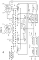
- FIG. 3 is a schematic diagram of stop control according to the second exemplary embodiment of the present disclosure.
- electric trolley 100a according to the second exemplary embodiment differences from electric trolley 100 according to the first exemplary embodiment will be mainly described. Specifically, in electric trolley 100a according to the second exemplary embodiment, a connection relationship between the detector, the safety controller, and the driving commander is different.
- detector 107 is connected only to safety controller 113a.
- Driving commander 110a acquires information output by detector 107 via safety controller 113a.
- safety controller 113a includes manager 114.
- Manager 114 manages detector 107, acquires the information output by detector 107, and outputs the acquired information to driving commander 110a.
- safety controller 113a acquires the information output from detector 107 prior to driving commander 110a, and confirms content thereof. Therefore, safety controller 113a can confirm information to be input to driving commander 110a. Further, safety controller 113a can guarantee that driving commander 110a and safety controller 113a are operated according to information of the same detector 107. Since detector 107 has a single output destination, detector 107 can be applied even to a detector in which it is difficult to branch an output signal.
- Safety controller 113a may output the information from detector 107 to driving commander 110a only in a case where it is determined to be a safety state based on the information from detector 107. In this case, safety controller 113a can operate driving commander 110a based on the information of detector 107 which determines the safe state.
- feedback to detector 107 is provided from two systems including driving commander 110 and safety controller 113.
- manager 114 can centrally manage the feedback to detector 107.
- FIG. 4 is a schematic diagram of stop control according to the third exemplary embodiment of the present disclosure.
- electric trolley 100b according to the third exemplary embodiment differences from electric trolley 100 according to the first exemplary embodiment will be mainly described. Specifically, electric trolley 100b according to the third exemplary embodiment has a function of monitoring operations of operation blocker 111 and control blocker 112.
- safety controller 113b includes first monitor 115 and second monitor 116.
- First monitor 115 monitors a signal output from operation blocker 111 to motor driver 109.
- Second monitor 116 monitors a signal output from control blocker 112 to motor driver 109.
- safety controller 113b can confirm whether or not operation blocker 111 and control blocker 112 normally function.
- Safety controller 113b may include a single monitor that integrates the functions of the two monitors.
- safety controller 113a according to the second exemplary embodiment may include first monitor 115 and second monitor 116.
- FIG. 5 is a schematic diagram of stop control according to the fourth exemplary embodiment of the present disclosure.
- electric trolley 100c according to the fourth exemplary embodiment differences from electric trolley 100 according to the first exemplary embodiment will be mainly described. Specifically, in electric trolley 100c according to the fourth exemplary embodiment, a configuration in which the operation blocking signal is output is independent of a configuration in which the control blocking signal is output.
- safety controller 113c includes first determiner 117 and second determiner 118.
- first determiner 117 determines that it is necessary to stop driving of electric trolley 100c based on information from detector 107
- first determiner 117 outputs the operation blocking signal to operation blocker 111.
- second monitor 116 determines that it is necessary to stop the driving of electric trolley 100c based on the information from detector 107
- second monitor 116 outputs the control blocking signal to control blocker 112.
- first determiner 117 and second determiner 118 are separately configured by separating cores in the same microcomputer. More desirably, first determiner 117 and second determiner 118 may be physically configured separately by being configured by separate microcomputers or the like.
- First determiner 117 and second determiner 118 perform mutual monitoring and monitor that other determiners normally operate. As a result, even in a case where first determiner 117 or second determiner 118 fails, the blocking signal by the other determiner is reliably output.
- the electric trolley of the present disclosure is useful in an area where indoor and outdoor movement is required.
Landscapes
- Engineering & Computer Science (AREA)
- Mechanical Engineering (AREA)
- Transportation (AREA)
- Power Engineering (AREA)
- Life Sciences & Earth Sciences (AREA)
- Public Health (AREA)
- Veterinary Medicine (AREA)
- General Health & Medical Sciences (AREA)
- Health & Medical Sciences (AREA)
- Animal Behavior & Ethology (AREA)
- Sustainable Development (AREA)
- Sustainable Energy (AREA)
- Electric Propulsion And Braking For Vehicles (AREA)
- Handcart (AREA)
- Regulating Braking Force (AREA)
Abstract
Description
- The present disclosure relates to an electric trolley having an automatic driving function and a steering support function.
- There is a human-boarding type electric trolley, such as an electric wheelchair, having a function of not only travelling by being operated by a person but also detecting an obstacle by an obstacle detection sensor to stop the electric trolley. In the electric trolley, in a case where an abnormality occurs in the electric trolley, the electric trolley is stopped to prevent danger due to rough driving or collision, so that safety is ensured. In the related art, in order to stop an electromotor that performs driving for travel, interruption of a power supply circuit that supplies electric power to the electromotor is performed in a case where an abnormality occurs (PTL 1).
- PTL 1:
Japanese Patent No. 4134719 - According to the present disclosure, there is provided an electric trolley that travels by controlling a motor fitted to a driving wheel of the electric trolley using a motor driver of the electric trolley, the electric trolley including a safety controller that determines whether or not to stop driving of the driving wheel, and a driving commander that outputs, to the motor driver, (i) an operation permission signal for permitting the motor to be operated and (ii) a control signal for controlling an operation of the motor, in which, when the safety controller determines to stop the driving of the driving wheel, the safety controller performs control to stop inputs of the operation permission signal and the control signal to the motor driver.
-
-
FIG. 1 is a schematic diagram of an electric trolley according to a first exemplary embodiment of the present disclosure. -
FIG. 2 is a schematic diagram of stop control according to the first exemplary embodiment of the present disclosure. -
FIG. 3 is a schematic diagram of stop control according to a second exemplary embodiment of the present disclosure. -
FIG. 4 is a schematic diagram of stop control according to a third exemplary embodiment of the present disclosure. -
FIG. 5 is a schematic diagram of stop control according to a fourth exemplary embodiment of the present disclosure. - As described above, in the related art, in a case where an abnormality occurs in an electric trolley, driving of an electromotor is stopped by interrupting a power supply circuit, so that safety is ensured. However, in order to interrupt a large current supplied to the electromotor, an interruption circuit often becomes large and a weight also becomes large.
- An object of the present disclosure is to provide an electric trolley capable of mounting a configuration capable of stopping travel more reliably with a small size and a light weight.
- Hereinafter, exemplary embodiments of the present disclosure will be described with reference to the accompanying drawings. The same components are designated by the same reference numerals. In addition, the drawings are schematically shown with each component as a subject for easy understanding.
- An electric trolley of the present disclosure will be described with reference to
FIGS. 1 and2 .FIG. 1 is a schematic diagram ofelectric trolley 100, which is viewed from a side surface, according to a first exemplary embodiment of the present disclosure. In addition,FIG. 2 is a schematic diagram of stop control according to the first exemplary embodiment of the present disclosure. -
Electric trolley 100 includesmain frame 101,training wheel 102,driving wheel 103,motor 104,brake 105,power supply 106,detector 107, andcontrol box 108.Power supply 106 is a high voltage power supply, and supplies electric power tomotor driver 109,motor 104, andbrake 105, which will be described later. That is, as shown inFIG. 2 ,power supply 106,motor driver 109,motor 104, andbrake 105 belong to a high voltage power supply system. -
Main frame 101 is provided withseat 101A,footrest 101B,backrest 101C, andarmrest 101D. Armrest 101D is provided with joystick 101E. - A pair of
training wheels 102 are installed on left and right sides at a front ofelectric trolley 100. A pair ofdriving wheels 103 are installed on left and right sides at a rear ofelectric trolley 100, and freely rotate around a rotation shaft (not shown) ofmotor 104. Motor 104 is provided for each of left andright driving wheels 103, and drives each of left and right drivingwheels 103 independently. Brake 105 is provided for each of left andright driving wheels 103, and brakes each of left andright driving wheels 103.Power supply 106 supplies electric power tomotor 104. -
Detector 107 includes at least one ofobstacle detector 107A,area detector 107B,speed detector 107C, andstep detector 107D which is an example of a road surface detector.Detector 107 is connected to drivingcommander 110 andsafety controller 113, which will be described later. -
Obstacle detector 107A is disposed, for example, near a front ofelectric trolley 100.Obstacle detector 107A detects an obstacle by measuring a distance to a surrounding object, and outputs detected information tosafety controller 113, which will be described later. Specifically,obstacle detector 107A is, for example, a laser sensor, which irradiates a periphery ofelectric trolley 100 with infrared laser light to scan a fan-shaped field centered on the sensor by approximately 270 degrees in a horizontal direction with a fine pitch such as every 0.36 degrees. Further,obstacle detector 107A detects the distance to the surrounding object based on time until reflected light is observed. A Time of Flight (TOF) sensor may be used asobstacle detector 107A. In this case,obstacle detector 107A is realized by a simple configuration rather than the laser sensor. In addition, a stereo camera may be used asobstacle detector 107A. In this case,obstacle detector 107A can acquire color information and the like in addition to depth information. Therefore, it is possible to acquire more detailed information about a surrounding environment and an obstacle and it is possible to realize highly accurate operation control and accurate obstacle avoidance. -
Area detector 107B is disposed, for example, near the front ofelectric trolley 100.Area detector 107B detects area information of indicating whether a current travel area is a travelable area where the electric trolley can travel safely or a dangerous area, and outputs the detected area information tosafety controller 113. Specifically,area detector 107B receives a signal from a signal transmitter fixed to a travel environment side, and detects an area of the current travel area. -
Speed detector 107C is connected to, for example,motor 104 or is disposed in the vicinity ofmotor 104.Speed detector 107C detects a travel speed ofelectric trolley 100 and outputs information of the detected speed tosafety controller 113. Specifically,speed detector 107C calculates rotation speeds ofmotor 104 anddriving wheel 103 by reading a rotation angle ofmotor 104, and detects the travel speed ofelectric trolley 100. -
Step detector 107D is disposed, for example, near the front ofelectric trolley 100.Step detector 107D detects a step on a travel road surface and outputs information of the detected step tosafety controller 113. Specifically,step detector 107D is, for example, a laser sensor, which irradiates the periphery ofelectric trolley 100 with infrared laser light to scan the fan-shaped field centered on the sensor by approximately 270 degrees in a height direction with the fine pitch such as every 0.36 degrees. Further,step detector 107D detects a distance to the travel road surface based on the time until the reflected light is observed. Further, it is determined that a step exists on the travel road surface based on a predetermined condition such as a case where the distance to the travel road surface is not continuous or a case where the distance is significantly changed. The TOF sensor may be used asstep detector 107D. In this case,step detector 107D is realized by a simpler configuration than the laser sensor. In addition, a stereo camera may be used asstep detector 107D. In this case,step detector 107D can acquire color information and the like in addition to the depth information. Therefore, it is possible to acquire more detailed information about the step and it is possible to realize highly accurate operation control and accurate step avoidance. - In each of
obstacle detector 107A,area detector 107B,speed detector 107C, andstep detector 107D, a configuration of a sensor and the like for detecting state information may be grouped with a configuration of a processor and the like for converting the detected state information into information to be output tosafety controller 113 or for calculating the state information. - The information detected by
detector 107 may be further used for improving travel property ofelectric trolley 100 such as obstacle avoidance and path generation. At this time, it is desirable that, instead ofsafety controller 113, drivingcommander 110, which will be described later, performs control to improve the travel property based on the information detected bydetector 107. That is, it is desirable that a configuration in which the detected information bydetector 107 is processed and output for improving the travel property is separately configured from a configuration in which the detected information is processed and output for improving safety. As a result, even in a case where a failure or defect occurs in any of the configurations and an abnormality occurs in the control, the operation ofelectric trolley 100 can be stopped by the other configuration. For example, in a case where an abnormality occurs in the control performed by drivingcommander 110,safety controller 113 performs control to stop the driving ofelectric trolley 100 based on the information detected bydetector 107, as will be described later. In addition, in a case where an abnormality occurs in the control performed bysafety controller 113, drivingcommander 110 performs control to stop the driving ofelectric trolley 100 based on the operation amount ofjoystick 101E. -
Control box 108 is provided withmotor driver 109, drivingcommander 110,operation blocker 111,control blocker 112, andsafety controller 113. As described above,motor driver 109 belongs to the high voltage power supply system, but drivingcommander 110,operation blocker 111,control blocker 112, andsafety controller 113 belong to a low voltage power supply system. The electric power is supplied frompower supply 106 to drivingcommander 110,safety controller 113, and the like, which belong to the low voltage power supply system via, for example, a step-down transformer. - It is preferable that
control box 108,power supply 106, and the like are provided separately fromseat 101A,backrest 101C, and the like in order to reduce discomfort to a passenger due to exhausted heat. In addition, it is preferable thatcontrol box 108,power supply 106, and the like are provided underelectric trolley 100 in order to reduce instability because a center of gravity ofelectric trolley 100 becomes high. - In a case where the electric power for operation is supplied from
power supply 106,motor driver 109 controls the rotation of eachmotor 104 to operatemotor 104. -
Motor driver 109 is in a state in which motor 104 can be controlled by inputting an operation permission signal from drivingcommander 110. Thereafter,motor driver 109 controls rotation ofmotor 104 so as to operatemotor 104 according to a control signal input from drivingcommander 110. That is,motor driver 109 does not controlmotor 104 unless the operation permission signal is input from drivingcommander 110. For example,motor driver 109 does not controlmotor 104 in a case where the control signal is input from drivingcommander 110 in a state in which the operation permission signal is not input from drivingcommander 110. - In a case where driving
commander 110 can give a command tomotor driver 109, drivingcommander 110 outputs the operation permission signal tomotor driver 109. Thereafter, in a case where the operation amount ofjoystick 101E is input, drivingcommander 110 determines a rotation speed ofmotor 104 based on the operation amount ofjoystick 101E, and outputs the control signal tomotor driver 109. Here, the control signal includes a control value based on the rotation speed ofmotor 104. - Here, the case where driving
commander 110 can give the command tomotor driver 109 will be described. For example, in a case where drivingcommander 110 detects rise ofpower supply 106 ofelectric trolley 100, drivingcommander 110 may transmit the operation permission signal. That is, drivingcommander 110 transmits the operation permission signal in a case where the travel control becomes possible. At this time, in a case where drivingcommander 110 detects thatelectric trolley 100 is stopped for a predetermined period for saving electric power, drivingcommander 110 may stop transmission of the operation permission signal. In addition, drivingcommander 110 may transmit the operation permission signal in a case where a failure ofdetector 107, an abnormality ofsafety controller 113, or the like is not generated andelectric trolley 100 does not have a problem on travel. Here, the abnormality indicates, for example, a state in which power is not supplied todetector 107, a state in which communication between communication configurations cannot be performed, and the like. Drivingcommander 110 confirms whether or not the states occur by inputting the detected information fromdetector 107 or performing communication. It is preferable that drivingcommander 110 transmits the operation permission signal in a case where the states do not occur. In addition, drivingcommander 110 may transmit the operation permission signal in a case where it is determined that there is no problem on the travel in the surrounding environment ofelectric trolley 100 based on the detected information bydetector 107. In addition, drivingcommander 110 may transmit the operation permission signal in a case where an instruction is input by a manual operation by a user. For example, the transmission of the operation permission signal may be performed in a case where a brake device included inelectric trolley 100 is released by a passenger, or an instruction of the user to operateelectric trolley 100 may be input using a terminal or the like capable of communicating withelectric trolley 100. In addition, the case where drivingcommander 110 can give the command tomotor driver 109 may be automatically determined by drivingcommander 110 or may be input manually. - Driving
commander 110 may continuously transmit the operation permission signal while determining to be capable of giving the command tomotor driver 109, and may stop transmission of the operation permission signal in a case of not being capable of giving the command tomotor driver 109. - In this way, operation commander 10 transmits the operation permission signal in addition to the control signal. As a result, even in a case where operation commander 10 erroneously transmits the control signal, the erroneously transmitted control signal can be invalidated by not transmitting the operation permission signal. Therefore, safety can be improved.
- Not only the operation amount of
joystick 101E but also information related to, for example, a preset speed may be further used for determination of the rotation speed ofmotor 104 by drivingcommander 110. In a case where the maximum speed is preset, drivingcommander 110 determines the rotation speed ofmotor 104 so thatelectric trolley 100 operates at a speed which is equal to or less than the set maximum speed. Drivingcommander 110 may output the operation permission signal or the control signal at the same time to each ofmotor drivers 109, or may perform individual input. In addition,joystick 101E may have another form such as a handle or a remote controller. - In a case where an operation blocking signal is input from
safety controller 113,operation blocker 111 blocks the operation permission signal input from drivingcommander 110 tomotor driver 109. In a case where the operation blocking signal is not input fromsafety controller 113,operation blocker 111 does not block the operation permission signal output from drivingcommander 110 tomotor driver 109. -
Operation blocker 111 is a switching element, and is configured with, for example, a tri-state buffer. A configuration is used in whichoperation blocker 111 is provided for eachmotor driver 109 one by one, but the present disclosure is not limited thereto, and the operation permission signal input from drivingcommander 110 to eachmotor driver 109 may be blocked by oneoperation blocker 111. However, in a case whereoperation blocker 111 is provided for eachmotor driver 109 one by one, it is possible to causeoperation blocker 111 to easily correspond to specification of eachmotor driver 109 in a case wheremotor driver 109 is replaced according todriving wheel 103 ormotor 104, in a case where the number ofmotor drivers 109 is increased or decreased, and the like. - In the case where the control blocking signal is input from
safety controller 113,control blocker 112 blocks the control signal input from drivingcommander 110 tomotor driver 109. In the case where the control blocking signal is not input fromsafety controller 113,control blocker 112 does not block the control signal output from drivingcommander 110 tomotor driver 109. -
Control blocker 112 is a switching element, and is configured with, for example, a tri-state buffer. A configuration is used in which controlblocker 112 is provided for eachmotor driver 109 one by one, but the present disclosure is not limited thereto, and the operation permission signal input from drivingcommander 110 to eachmotor driver 109 may be blocked by onecontrol blocker 112. However, in a case wherecontrol blocker 112 is provided for eachmotor driver 109 one by one, it is possible to causecontrol blocker 112 to easily correspond to the specification of eachmotor driver 109 in the case wheremotor driver 109 is replaced according todriving wheel 103 ormotor 104, in the case where the number ofmotor drivers 109 is increased or decreased, and the like. -
Safety controller 113 determines whether or not it is necessary to stop the driving ofelectric trolley 100 based on the information input fromdetector 107. In a case wheresafety controller 113 determines that it is necessary to stop the driving ofelectric trolley 100,safety controller 113 outputs the operation blocking signal tooperation blocker 111 and the control blocking signal to controlblocker 112, respectively, through paths independent of each other, and stops driving ofmotor 104. That is,safety controller 113 includes at least one of a connector for inputting the operation blocking signal tooperation blocker 111 and a connector for inputting the control blocking signal to controlblocker 112. -
Safety controller 113 stops an operation ofmotor driver 109 by controlling the output of the operation permission signal and an operation ofmotor 104 independently of each other. In the present exemplary embodiment,safety controller 113 stops the control ofmotor 104 bymotor driver 109 by controllingoperation blocker 111 andcontrol blocker 112 independently of each other. As a result, two circuits exist for inputting signals for stopping the driving ofmotor 104, so that the driving ofmotor 104 can be stopped more reliably. In addition,safety controller 113 may brake drivingwheel 103 by operatingbrake 105 by inputting a brake signal to brake 105 in a case where the speed is not sufficiently reduced at the same time or after a certain time elapses. The case where the speed is not sufficiently decelerated indicates, for example, a case where the speed is not zero. As a result, three circuits exist for inputting signals for stopping the driving ofmotor 104, so that the driving ofmotor 104 can be stopped more reliably. - Here,
safety controller 113 determines whether or not it is necessary to stop the driving ofelectric trolley 100, for example, as follows. - In a case where
safety controller 113 detects that a speed ofelectric trolley 100, which is detected byspeed detector 107C, exceeds, for example, a preset speed,safety controller 113 determines that it is necessary to stop the driving ofelectric trolley 100. At this time, specifically, a situation is conceivable in whichmotor driver 109 is not normally controlled due to an abnormality or the like in drivingcommander 110, so that there is a problem in that rough driving or collision occurs. - Alternatively,
safety controller 113 determines that it is necessary to stop the driving ofelectric trolley 100 in a case whereobstacle detector 107A detects an obstacle in a very vicinity. At this time, specifically, there is a problem in that a collision with the obstacle in the vicinity may occur. Alternatively, more simply, in a case whereobstacle detector 107A detects an obstacle in a predetermined area,safety controller 113 may determine that it is necessary to stop the driving ofelectric trolley 100. At this time, the driving ofelectric trolley 100 is stopped at a time in which the obstacle separated fromelectric trolley 100 by a certain distance is detected, so that the collision can be prevented. - Alternatively,
safety controller 113 determines that it is necessary to stop the driving ofelectric trolley 100 based on the speed ofelectric trolley 100 detected byspeed detector 107C and the distance to the surrounding obstacle detected byobstacle detector 107A. More specifically,safety controller 113 estimates a travel trace in a case whereelectric trolley 100 is braked based on a current travel speed ofelectric trolley 100 detected byspeed detector 107C, and determines that it is necessary to stop the driving ofelectric trolley 100 in a case where the obstacle is detected byobstacle detector 107A inside the travel trace. At this time, the obstacle exists in the estimated travel path ofelectric trolley 100, so that there is a problem in that a collision occurs. - Alternatively,
safety controller 113 determines that it is necessary to stop the driving ofelectric trolley 100 in a case wherestep detector 107D detects a concave step on the travel road surface. At this time, specifically, it is conceivable thatelectric trolley 100 is overturned or falls due to the concave step, so that there is a problem in that overturn of the passenger or harm of a surrounding person below the concave step occurs. - Alternatively,
safety controller 113 determines that it is necessary to stop the driving ofelectric trolley 100 based on the area information detected byarea detector 107B. Specifically,safety controller 113 determines whether or not it is necessary to stop the driving ofelectric trolley 100 based on whether or not the current travel area is the dangerous area. For example,safety controller 113 may determine the travelable area while the transmitter is installed in the travelable area andsafety controller 113 receives the signal, andsafety controller 113 may determine the dangerous area in a case where the signal is blocked. In addition, in a case where the transmitter is installed in the dangerous area andsafety controller 113 receives a signal,safety controller 113 may determine the dangerous area. In addition, an ID and attribute information may be added to the signal of the signal transmitter installed on the travel environment, andsafety controller 113 may determine whether the travel area is the travelable area or the dangerous area based on the added content. - Although driving
commander 110 andsafety controller 113 may be configured on the same microcomputer, it is desirable that drivingcommander 110 andsafety controller 113 are separately configured by separating cores in the microcomputer. More desirably, drivingcommander 110 andsafety controller 113 may be physically configured separately by being configured by separate microcomputers or the like. As a result, even in a case where a failure or defect occurs in any of drivingcommander 110 andsafety controller 113 and an abnormality occurs in the control, the operation ofelectric trolley 100 can be stopped by the other. For example, in a case where an abnormality occurs in the control performed by drivingcommander 110,safety controller 113 performs control to stop the driving ofelectric trolley 100 based on the information detected bydetector 107. In addition, in a case where an abnormality occurs in the control performed bysafety controller 113, for example, a fact of the occurrence of the abnormality is notified to the user by using a display device, a notification device, or the like. As a result, a side of the user can recognize thatsafety controller 113 cannot be operated, thereby contributing to performing control to stop the driving ofelectric trolley 100 by drivingcommander 110 based on the operation amount ofjoystick 101E by the user. In addition, for example, in a case where an abnormality occurs in the control performed bysafety controller 113,safety controller 113 may be designed so thatsafety controller 113 automatically outputs the operation blocking signal and the control blocking signal. By doing so, the driving ofelectric trolley 100 can be stopped at a time in which an abnormality occurs insafety controller 113, and travel can be performed with higher safety. - In a case where
safety controller 113 is configured,detector 107 is disposed onelectric trolley 100 to be connected tosafety controller 113 by wire or wirelessly. Alternatively,detector 107, which is already mounted onelectric trolley 100, andsafety controller 113 are connected by wire or wirelessly. Next,operation blocker 111 is disposed between the connectors for inputting the operation permission signal from drivingcommander 110 tomotor driver 109, andoperation blocker 111 andsafety controller 113 are connected in wired or wirelessly. In addition,control blocker 112 is disposed between connectors for inputting the control signal from drivingcommander 110 tomotor driver 109, andcontrol blocker 112 andsafety controller 113 are connected in wired or wirelessly. However, it is desirable thatoperation blocker 111,control blocker 112, andsafety controller 113 react at a response speed as fast as possible, and a wired connection is preferable. - Driving
commander 110 andsafety controller 113 may be realized by a computer program. A computer that realizes the above-describeddriving commander 110 andsafety controller 113 using the program may illustratively include a processor, an output device, a memory, a storage, and a power supply circuit. The components are connected to a bus and can communicate with each other. - The processor is an example of a circuit or device having arithmetic capacity. As the processor, for example, at least one of a Central Processing Unit (CPU), a Micro Processing Unit (MPU), and a Graphics Processing Unit (GPU) may be used.
- The output device may include, for example, a display (or monitor).
- The memory stores, for example, a program executed by the processor and data or information processed according to the execution of the program. The memory may include a Random Access Memory (RAM) and a Read Only Memory (ROM). The RAM may be used as a work memory of the processor. The "program" may be referred to as "software" or "application".
- The storage stores the program executed by the processor and data or information processed according to the execution of the program. The storage may include, for example, a semiconductor drive device such as a Hard Disk Drive (HDD) or a Solid State Drive (SSD). In addition to or in place of the semiconductor drive device, a non-volatile memory, such as a flash memory, may be included in the storage.
- The program and/or data may be provided in the form of being recorded on a computer (processor) readable recording medium. A flexible disc, a CD-ROM, a CD-R, a CD-RW, an MO, a DVD, a Blu-ray disc, a portable hard disk, and the like may be provided as examples of the recording media. In addition, semiconductor memories, such as a Universal Serial Bus (USB) and a memory, are also examples of recording media.
- In addition, the program and/or data may be provided (downloaded), for example, from a server to the computer via a communication line. For example, the program and/or the data may be provided to the computer via a communication device and may be stored in the memory and/or the storage. The program and/or data may also be provided to the computer via an input device and may be stored in the memory and/or the storage.
- In the present exemplary embodiment, an example is shown in which
operation blocker 111 blocks the operation permission signal output from drivingcommander 110 tomotor driver 109, but the present disclosure is not limited thereto. For example, the operation permission signal may be generated by dividing a voltage frompower supply 106. Even in this case,operation blocker 111 is configured to block the operation permission signal. In addition, the operation ofmotor driver 109 may be stopped by outputting an operation non-permission signal, which is used to prevent the operation permission signal from being output, fromsafety controller 113 to drivingcommander 110 without providingoperation blocker 111. In addition, the operation ofmotor driver 109 may be stopped by outputting the control signal, which is used to reduce the amount of electric power to be supplied tomotor 104 to 0, fromsafety controller 113 to drivingcommander 110 without providingcontrol blocker 112. -
Safety controller 113 may release the blocking after confirming that the stop ofelectric trolley 100 elapses for a certain time based on the travel speed ofelectric trolley 100 detected byspeed detector 107C. Specifically, in a case wheresafety controller 113 confirms that the stop ofelectric trolley 100 elapses for the certain time,safety controller 113 stops the output of the control blocking signal and the operation blocking signal. Alternatively,safety controller 113 may confirm that there is no problem on the travel in the surrounding environment ofelectric trolley 100 based on the detected information bydetector 107, and may release the blocking. Specifically,safety controller 113 stops the output of the control blocking signal and the operation blocking signal based on any of a case where the obstacle is not detected byobstacle detector 107A, a case where the current travel area detected byarea detector 107B is not the dangerous area, and a case where the step is not detected bystep detector 107D. Alternatively,safety controller 113 may release the blocking by a manual operation by the user. Specifically, in a case where an instruction to release the blocking is input using the input device (which may be, for example, a device, such as a switch, that inputs only an intention or may be a device that includes a display unit, such as a touch panel, so as to present other information) by a passenger, a companion, or the like,safety controller 113 stops the output of the control blocking signal and the operation blocking signal. - A configuration included in
electric trolley 100 does not need to be limited to the disposition, a shape, and a size shown inFIG. 1 , and can be appropriately changed according to a design ofelectric trolley 100. - As described above, instead of the interruption circuit that interrupts the power supply circuit,
electric trolley 100 according to the present disclosure includesoperation blocker 111 that blocks the operation permission signal transmitted fromoperation commander 110, andcontrol blocker 112 that blocks the control signal. Since the power supply circuit belongs to the high voltage power supply system, the interruption circuit is large and heavy. On the other hand,operation blocker 111 andcontrol blocker 112, which are disposed between drivingcommander 110 andmotor driver 109, belong to the low voltage power supply system. Therefore,electric trolley 100 according to the present disclosure can mount a configuration capable of stopping travel more reliably with a small size and a light weight. -
Electric trolley 100a according to a second exemplary embodiment of the present disclosure will be described with reference toFIG. 3. FIG. 3 is a schematic diagram of stop control according to the second exemplary embodiment of the present disclosure. - Here, in
electric trolley 100a according to the second exemplary embodiment, differences fromelectric trolley 100 according to the first exemplary embodiment will be mainly described. Specifically, inelectric trolley 100a according to the second exemplary embodiment, a connection relationship between the detector, the safety controller, and the driving commander is different. - As shown in
FIG. 3 ,detector 107 is connected only tosafety controller 113a. Drivingcommander 110a acquires information output bydetector 107 viasafety controller 113a. - Specifically,
safety controller 113a includesmanager 114.Manager 114 managesdetector 107, acquires the information output bydetector 107, and outputs the acquired information to drivingcommander 110a. - That is,
safety controller 113a acquires the information output fromdetector 107 prior to drivingcommander 110a, and confirms content thereof. Therefore,safety controller 113a can confirm information to be input to drivingcommander 110a. Further,safety controller 113a can guarantee that drivingcommander 110a andsafety controller 113a are operated according to information of thesame detector 107. Sincedetector 107 has a single output destination,detector 107 can be applied even to a detector in which it is difficult to branch an output signal. -
Safety controller 113a may output the information fromdetector 107 to drivingcommander 110a only in a case where it is determined to be a safety state based on the information fromdetector 107. In this case,safety controller 113a can operate drivingcommander 110a based on the information ofdetector 107 which determines the safe state. - In
electric trolley 100 according to the first exemplary embodiment, feedback todetector 107 is provided from two systems including drivingcommander 110 andsafety controller 113. On the other hand, in the present exemplary embodiment,manager 114 can centrally manage the feedback todetector 107. -
Electric trolley 100b according to a third exemplary embodiment of the present disclosure will be described with reference toFIG. 4. FIG. 4 is a schematic diagram of stop control according to the third exemplary embodiment of the present disclosure. - Here, in
electric trolley 100b according to the third exemplary embodiment, differences fromelectric trolley 100 according to the first exemplary embodiment will be mainly described. Specifically,electric trolley 100b according to the third exemplary embodiment has a function of monitoring operations ofoperation blocker 111 andcontrol blocker 112. - As shown in
FIG. 4 ,safety controller 113b according to the present exemplary embodiment includesfirst monitor 115 andsecond monitor 116. First monitor 115 monitors a signal output fromoperation blocker 111 tomotor driver 109. Second monitor 116 monitors a signal output fromcontrol blocker 112 tomotor driver 109. - As a result, in a case where the operation blocking signal and the control blocking signal are output,
safety controller 113b can confirm whether or notoperation blocker 111 andcontrol blocker 112 normally function. -
Safety controller 113b may include a single monitor that integrates the functions of the two monitors. In addition,safety controller 113a according to the second exemplary embodiment may includefirst monitor 115 andsecond monitor 116. -
Electric trolley 100c according to a fourth exemplary embodiment of the present disclosure will be described with reference toFIG. 5. FIG. 5 is a schematic diagram of stop control according to the fourth exemplary embodiment of the present disclosure. - Here, in
electric trolley 100c according to the fourth exemplary embodiment, differences fromelectric trolley 100 according to the first exemplary embodiment will be mainly described. Specifically, inelectric trolley 100c according to the fourth exemplary embodiment, a configuration in which the operation blocking signal is output is independent of a configuration in which the control blocking signal is output. - As shown in
FIG. 5 ,safety controller 113c according to the present exemplary embodiment includesfirst determiner 117 andsecond determiner 118. In a case wherefirst determiner 117 determines that it is necessary to stop driving ofelectric trolley 100c based on information fromdetector 107,first determiner 117 outputs the operation blocking signal tooperation blocker 111. In a case wheresecond monitor 116 determines that it is necessary to stop the driving ofelectric trolley 100c based on the information fromdetector 107,second monitor 116 outputs the control blocking signal to controlblocker 112. - It is desirable that
first determiner 117 andsecond determiner 118 are separately configured by separating cores in the same microcomputer. More desirably,first determiner 117 andsecond determiner 118 may be physically configured separately by being configured by separate microcomputers or the like. -
First determiner 117 andsecond determiner 118 perform mutual monitoring and monitor that other determiners normally operate. As a result, even in a case wherefirst determiner 117 orsecond determiner 118 fails, the blocking signal by the other determiner is reliably output. - The electric trolley of the present disclosure is useful in an area where indoor and outdoor movement is required.
-
- 100
- Electric trolley
- 101
- Main frame
- 101A
- Seat
- 101B
- Footrest
- 101C
- Backrest
- 101D
- Armrest
- 101E
- Joystick
- 102
- Training wheel
- 103
- Driving wheel
- 104
- Motor
- 105
- Brake
- 106
- Power supply
- 107
- Detector
- 107A
- Obstacle detector
- 107B
- Area detector
- 107C
- Speed detector
- 107D
- Step detector (road surface detector)
- 108
- Control box
- 109
- Motor driver
- 110
- Driving commander
- 111
- Operation blocker
- 112
- Control blocker
- 113
- Safety controller
Claims (8)
- An electric trolley that travels by controlling a motor fitted to a driving wheel of the electric trolley using a motor driver of the electric trolley, the electric trolley comprising:a safety controller that determines whether or not to stop driving of the driving wheel; anda driving commander that outputs, to the motor driver, (i) an operation permission signal for permitting the motor to be operated and (ii) a control signal for controlling an operation of the motor, whereinwhen the safety controller determines to stop the driving of the driving wheel, the safety controller performs control to stop inputs of the operation permission signal and the control signal to the motor driver.
- The electric trolley of Claim 1, further comprising:an operation blocker that is provided between the driving commander and the motor driver, and blocks the operation permission signal based on an operation blocking signal input from the safety controller; anda control blocker that is provided between the driving commander and the motor driver, and blocks the control signal based on a control blocking signal input from the safety controller, whereinwhen the safety controller determines to stop the driving of the driving wheel, the safety controller outputs the operation blocking signal to the operation blocker and outputs the control blocking signal to the control blocker.
- The electric trolley of Claim 2, wherein
the safety controller outputs the operation blocking signal and the control blocking signal through mutually different paths. - The electric trolley of Claim 2 or 3, wherein
the safety controller operates a brake by inputting a brake signal to the brake for braking the driving wheel at the same time as outputting the operation blocking signal and the control blocking signal or when a speed is not reduced even though a certain time elapses after outputting the operation blocking signal and the control blocking signal. - The electric trolley of any one of Claims 1 to 4, further comprising:an obstacle detector that detects an obstacle around the electric trolley, whereinthe safety controller determines whether or not to stop the driving of the driving wheel based on information related to the obstacle detected by the obstacle detector.
- The electric trolley of any one of Claims 1 to 5, further comprising:a speed detector that detects a speed of the electric trolley, whereinthe safety controller determines whether or not to stop the driving of the driving wheel based on information related to the speed of the electric trolley detected by the speed detector.
- The electric trolley of any one of Claims 1 to 6, further comprising:a road surface detector that detects a state of a road surface on which the electric trolley travels, whereinthe safety controller determines whether or not to stop the driving of the driving wheel based on information related to the road surface detected by the road surface detector.
- The electric trolley of any one of Claims 1 to 7, further comprising:an area detector that detects area information indicating whether an area in which the electric trolley travels is a travelable area where the electric trolley can travel safely or a dangerous area, whereinthe safety controller determines whether or not to stop the driving of the driving wheel based on the area information detected by the area detector.
Applications Claiming Priority (2)
| Application Number | Priority Date | Filing Date | Title |
|---|---|---|---|
| JP2019143747 | 2019-08-05 | ||
| PCT/JP2020/028822 WO2021024847A1 (en) | 2019-08-05 | 2020-07-28 | Electric trolley |
Publications (3)
| Publication Number | Publication Date |
|---|---|
| EP4011682A1 true EP4011682A1 (en) | 2022-06-15 |
| EP4011682A4 EP4011682A4 (en) | 2022-09-21 |
| EP4011682B1 EP4011682B1 (en) | 2024-12-18 |
Family
ID=74503788
Family Applications (1)
| Application Number | Title | Priority Date | Filing Date |
|---|---|---|---|
| EP20849267.8A Active EP4011682B1 (en) | 2019-08-05 | 2020-07-28 | Electric trolley |
Country Status (5)
| Country | Link |
|---|---|
| US (1) | US11932119B2 (en) |
| EP (1) | EP4011682B1 (en) |
| JP (1) | JP7462136B2 (en) |
| CN (1) | CN114007892B (en) |
| WO (1) | WO2021024847A1 (en) |
Families Citing this family (2)
| Publication number | Priority date | Publication date | Assignee | Title |
|---|---|---|---|---|
| JP7055497B1 (en) | 2021-03-31 | 2022-04-18 | 学校法人久留米工業大学 | Road surface monitoring device |
| JP7667704B2 (en) | 2021-07-15 | 2025-04-23 | 株式会社マキタ | Transport vehicle |
Family Cites Families (16)
| Publication number | Priority date | Publication date | Assignee | Title |
|---|---|---|---|---|
| US4634941A (en) * | 1981-04-15 | 1987-01-06 | Invacare Corporation | Electric wheelchair with improved control circuit |
| US4387325A (en) * | 1981-04-15 | 1983-06-07 | Invacare Corporation | Electric wheelchair with speed control circuit |
| JPH0386005A (en) | 1989-08-28 | 1991-04-11 | Matsushita Electric Works Ltd | Motor chair |
| FR2744630B1 (en) * | 1996-02-09 | 1998-05-15 | Ecole Superieure Atlantique D | MOTORIZED WHEELCHAIR WITH VOICE CONTROL DEVICE SUPERVISED BY A SECURITY DEVICE, AND METHOD FOR CONTROLLING AND SECURING THE MOVEMENT OF SUCH A CHAIR |
| JPH1094106A (en) | 1996-09-17 | 1998-04-10 | Yamaha Motor Co Ltd | Electric vehicle drive system |
| JP3957101B2 (en) * | 1997-04-01 | 2007-08-15 | ナブテスコ株式会社 | Control device for electric vehicle |
| JP2003334218A (en) * | 2002-05-22 | 2003-11-25 | Matsushita Electric Ind Co Ltd | Electric wheelchair |
| JP4134719B2 (en) | 2002-12-27 | 2008-08-20 | トヨタ自動車株式会社 | Power supply system shutdown control method |
| JP2005323470A (en) | 2004-05-11 | 2005-11-17 | Atex Co Ltd | Brake controller for motor vehicle |
| US7360792B2 (en) * | 2004-10-20 | 2008-04-22 | Pride Mobility Products Corporation | Power wheelchair |
| JP2011218075A (en) * | 2010-04-14 | 2011-11-04 | Quest Engineering:Kk | Electric wheelchair |
| JP5673467B2 (en) * | 2011-09-16 | 2015-02-18 | パナソニック株式会社 | Collision prevention system and electric vehicle |
| CN202440196U (en) * | 2012-02-16 | 2012-09-19 | 湖南海诺电梯有限公司 | Device for avoiding obstacle of wheel chair lifting ladder |
| KR101514015B1 (en) * | 2013-10-08 | 2015-04-21 | 최준환 | Electric Rotary wheelchairs |
| JP6870321B2 (en) | 2016-09-12 | 2021-05-12 | スズキ株式会社 | Accelerator device for electric vehicles |
| CN109478069A (en) * | 2017-04-13 | 2019-03-15 | 松下电器产业株式会社 | control method of electric vehicle and electric vehicle |
-
2020
- 2020-07-28 WO PCT/JP2020/028822 patent/WO2021024847A1/en not_active Ceased
- 2020-07-28 EP EP20849267.8A patent/EP4011682B1/en active Active
- 2020-07-28 JP JP2021537238A patent/JP7462136B2/en active Active
- 2020-07-28 CN CN202080045569.3A patent/CN114007892B/en active Active
-
2021
- 2021-12-22 US US17/559,630 patent/US11932119B2/en active Active
Also Published As
| Publication number | Publication date |
|---|---|
| CN114007892B (en) | 2024-04-05 |
| JPWO2021024847A1 (en) | 2021-02-11 |
| CN114007892A (en) | 2022-02-01 |
| EP4011682B1 (en) | 2024-12-18 |
| JP7462136B2 (en) | 2024-04-05 |
| EP4011682A4 (en) | 2022-09-21 |
| US20220111738A1 (en) | 2022-04-14 |
| WO2021024847A1 (en) | 2021-02-11 |
| US11932119B2 (en) | 2024-03-19 |
Similar Documents
| Publication | Publication Date | Title |
|---|---|---|
| US11932119B2 (en) | Electric trolley | |
| JP5161353B2 (en) | Electric vehicle and control method thereof | |
| EP3968115B1 (en) | Movable body, control device, monitoring device, control method, and storage medium | |
| US20180264972A1 (en) | Vehicle controlled by remote controller and posture | |
| JP6989551B2 (en) | Mobiles, controls, ambient object detectors, and monitoring devices | |
| US20110036668A1 (en) | Electronic safety system for an elevator | |
| KR102518003B1 (en) | Elevator system comprising a safety monitoring system with a master/slave hierarchy | |
| CN112238869B (en) | Vehicle Controls | |
| KR101249710B1 (en) | Braking system for a lift truck | |
| WO2018181807A1 (en) | Vehicular brake system | |
| CN104755233A (en) | Robot control with improved safety | |
| US20190270450A1 (en) | Method for controlling electrically driven vehicle, and electrically driven vehicle | |
| KR20110060306A (en) | Vehicle collision and collision prevention device and method | |
| CN113581098B (en) | Vehicle control system | |
| JP6052114B2 (en) | Driving force control device | |
| JP2015154608A (en) | Control method of moving body and its maximum speed | |
| US20220105908A1 (en) | Method for controlling automobile and automobile system | |
| CN112744266B (en) | Central control method, device and control system for train operation | |
| JP7521639B2 (en) | Driving Control System | |
| WO2020255547A1 (en) | Train security system, train security control method, and on-train device | |
| JP2015103227A (en) | Autonomous mobile | |
| CN112441076B (en) | Rail vehicle and control method and control system thereof | |
| JP2019064535A (en) | Vehicle control device and vehicle control method | |
| KR102727164B1 (en) | Apparatus and control method for autonmous driving | |
| KR102540791B1 (en) | System for warning rear collision of vehicles and method thereof |
Legal Events
| Date | Code | Title | Description |
|---|---|---|---|
| STAA | Information on the status of an ep patent application or granted ep patent |
Free format text: STATUS: THE INTERNATIONAL PUBLICATION HAS BEEN MADE |
|
| PUAI | Public reference made under article 153(3) epc to a published international application that has entered the european phase |
Free format text: ORIGINAL CODE: 0009012 |
|
| STAA | Information on the status of an ep patent application or granted ep patent |
Free format text: STATUS: REQUEST FOR EXAMINATION WAS MADE |
|
| 17P | Request for examination filed |
Effective date: 20211216 |
|
| AK | Designated contracting states |
Kind code of ref document: A1 Designated state(s): AL AT BE BG CH CY CZ DE DK EE ES FI FR GB GR HR HU IE IS IT LI LT LU LV MC MK MT NL NO PL PT RO RS SE SI SK SM TR |
|
| A4 | Supplementary search report drawn up and despatched |
Effective date: 20220824 |
|
| RIC1 | Information provided on ipc code assigned before grant |
Ipc: A61G 5/04 20130101ALI20220818BHEP Ipc: B60T 7/12 20060101ALI20220818BHEP Ipc: B60L 15/20 20060101AFI20220818BHEP |
|
| DAV | Request for validation of the european patent (deleted) | ||
| DAX | Request for extension of the european patent (deleted) | ||
| GRAP | Despatch of communication of intention to grant a patent |
Free format text: ORIGINAL CODE: EPIDOSNIGR1 |
|
| STAA | Information on the status of an ep patent application or granted ep patent |
Free format text: STATUS: GRANT OF PATENT IS INTENDED |
|
| INTG | Intention to grant announced |
Effective date: 20240718 |
|
| GRAS | Grant fee paid |
Free format text: ORIGINAL CODE: EPIDOSNIGR3 |
|
| GRAA | (expected) grant |
Free format text: ORIGINAL CODE: 0009210 |
|
| STAA | Information on the status of an ep patent application or granted ep patent |
Free format text: STATUS: THE PATENT HAS BEEN GRANTED |
|
| AK | Designated contracting states |
Kind code of ref document: B1 Designated state(s): AL AT BE BG CH CY CZ DE DK EE ES FI FR GB GR HR HU IE IS IT LI LT LU LV MC MK MT NL NO PL PT RO RS SE SI SK SM TR |
|
| REG | Reference to a national code |
Ref country code: CH Ref legal event code: EP |
|
| REG | Reference to a national code |
Ref country code: DE Ref legal event code: R096 Ref document number: 602020043474 Country of ref document: DE |
|
| REG | Reference to a national code |
Ref country code: IE Ref legal event code: FG4D |
|
| REG | Reference to a national code |
Ref country code: LT Ref legal event code: MG9D |
|
| PG25 | Lapsed in a contracting state [announced via postgrant information from national office to epo] |
Ref country code: HR Free format text: LAPSE BECAUSE OF FAILURE TO SUBMIT A TRANSLATION OF THE DESCRIPTION OR TO PAY THE FEE WITHIN THE PRESCRIBED TIME-LIMIT Effective date: 20241218 |
|
| PG25 | Lapsed in a contracting state [announced via postgrant information from national office to epo] |
Ref country code: FI Free format text: LAPSE BECAUSE OF FAILURE TO SUBMIT A TRANSLATION OF THE DESCRIPTION OR TO PAY THE FEE WITHIN THE PRESCRIBED TIME-LIMIT Effective date: 20241218 |
|
| PG25 | Lapsed in a contracting state [announced via postgrant information from national office to epo] |
Ref country code: BG Free format text: LAPSE BECAUSE OF FAILURE TO SUBMIT A TRANSLATION OF THE DESCRIPTION OR TO PAY THE FEE WITHIN THE PRESCRIBED TIME-LIMIT Effective date: 20241218 |
|
| PG25 | Lapsed in a contracting state [announced via postgrant information from national office to epo] |
Ref country code: NO Free format text: LAPSE BECAUSE OF FAILURE TO SUBMIT A TRANSLATION OF THE DESCRIPTION OR TO PAY THE FEE WITHIN THE PRESCRIBED TIME-LIMIT Effective date: 20250318 |
|
| REG | Reference to a national code |
Ref country code: NL Ref legal event code: MP Effective date: 20241218 |
|
| PG25 | Lapsed in a contracting state [announced via postgrant information from national office to epo] |
Ref country code: LV Free format text: LAPSE BECAUSE OF FAILURE TO SUBMIT A TRANSLATION OF THE DESCRIPTION OR TO PAY THE FEE WITHIN THE PRESCRIBED TIME-LIMIT Effective date: 20241218 Ref country code: GR Free format text: LAPSE BECAUSE OF FAILURE TO SUBMIT A TRANSLATION OF THE DESCRIPTION OR TO PAY THE FEE WITHIN THE PRESCRIBED TIME-LIMIT Effective date: 20250319 |
|
| PG25 | Lapsed in a contracting state [announced via postgrant information from national office to epo] |
Ref country code: RS Free format text: LAPSE BECAUSE OF FAILURE TO SUBMIT A TRANSLATION OF THE DESCRIPTION OR TO PAY THE FEE WITHIN THE PRESCRIBED TIME-LIMIT Effective date: 20250318 |
|
| PG25 | Lapsed in a contracting state [announced via postgrant information from national office to epo] |
Ref country code: NL Free format text: LAPSE BECAUSE OF FAILURE TO SUBMIT A TRANSLATION OF THE DESCRIPTION OR TO PAY THE FEE WITHIN THE PRESCRIBED TIME-LIMIT Effective date: 20241218 |
|
| REG | Reference to a national code |
Ref country code: AT Ref legal event code: MK05 Ref document number: 1752005 Country of ref document: AT Kind code of ref document: T Effective date: 20241218 |
|
| PG25 | Lapsed in a contracting state [announced via postgrant information from national office to epo] |
Ref country code: SM Free format text: LAPSE BECAUSE OF FAILURE TO SUBMIT A TRANSLATION OF THE DESCRIPTION OR TO PAY THE FEE WITHIN THE PRESCRIBED TIME-LIMIT Effective date: 20241218 |
|
| PG25 | Lapsed in a contracting state [announced via postgrant information from national office to epo] |
Ref country code: PL Free format text: LAPSE BECAUSE OF FAILURE TO SUBMIT A TRANSLATION OF THE DESCRIPTION OR TO PAY THE FEE WITHIN THE PRESCRIBED TIME-LIMIT Effective date: 20241218 |
|
| PG25 | Lapsed in a contracting state [announced via postgrant information from national office to epo] |
Ref country code: ES Free format text: LAPSE BECAUSE OF FAILURE TO SUBMIT A TRANSLATION OF THE DESCRIPTION OR TO PAY THE FEE WITHIN THE PRESCRIBED TIME-LIMIT Effective date: 20241218 |
|
| PG25 | Lapsed in a contracting state [announced via postgrant information from national office to epo] |
Ref country code: IS Free format text: LAPSE BECAUSE OF FAILURE TO SUBMIT A TRANSLATION OF THE DESCRIPTION OR TO PAY THE FEE WITHIN THE PRESCRIBED TIME-LIMIT Effective date: 20250418 |
|
| PG25 | Lapsed in a contracting state [announced via postgrant information from national office to epo] |
Ref country code: PT Free format text: LAPSE BECAUSE OF FAILURE TO SUBMIT A TRANSLATION OF THE DESCRIPTION OR TO PAY THE FEE WITHIN THE PRESCRIBED TIME-LIMIT Effective date: 20250421 |
|
| PG25 | Lapsed in a contracting state [announced via postgrant information from national office to epo] |
Ref country code: EE Free format text: LAPSE BECAUSE OF FAILURE TO SUBMIT A TRANSLATION OF THE DESCRIPTION OR TO PAY THE FEE WITHIN THE PRESCRIBED TIME-LIMIT Effective date: 20241218 |
|
| PG25 | Lapsed in a contracting state [announced via postgrant information from national office to epo] |
Ref country code: AT Free format text: LAPSE BECAUSE OF FAILURE TO SUBMIT A TRANSLATION OF THE DESCRIPTION OR TO PAY THE FEE WITHIN THE PRESCRIBED TIME-LIMIT Effective date: 20241218 Ref country code: RO Free format text: LAPSE BECAUSE OF FAILURE TO SUBMIT A TRANSLATION OF THE DESCRIPTION OR TO PAY THE FEE WITHIN THE PRESCRIBED TIME-LIMIT Effective date: 20241218 |
|
| PG25 | Lapsed in a contracting state [announced via postgrant information from national office to epo] |
Ref country code: SK Free format text: LAPSE BECAUSE OF FAILURE TO SUBMIT A TRANSLATION OF THE DESCRIPTION OR TO PAY THE FEE WITHIN THE PRESCRIBED TIME-LIMIT Effective date: 20241218 |
|
| PG25 | Lapsed in a contracting state [announced via postgrant information from national office to epo] |
Ref country code: CZ Free format text: LAPSE BECAUSE OF FAILURE TO SUBMIT A TRANSLATION OF THE DESCRIPTION OR TO PAY THE FEE WITHIN THE PRESCRIBED TIME-LIMIT Effective date: 20241218 |
|
| PG25 | Lapsed in a contracting state [announced via postgrant information from national office to epo] |
Ref country code: IT Free format text: LAPSE BECAUSE OF FAILURE TO SUBMIT A TRANSLATION OF THE DESCRIPTION OR TO PAY THE FEE WITHIN THE PRESCRIBED TIME-LIMIT Effective date: 20241218 |
|
| PG25 | Lapsed in a contracting state [announced via postgrant information from national office to epo] |
Ref country code: SE Free format text: LAPSE BECAUSE OF FAILURE TO SUBMIT A TRANSLATION OF THE DESCRIPTION OR TO PAY THE FEE WITHIN THE PRESCRIBED TIME-LIMIT Effective date: 20241218 |
|
| REG | Reference to a national code |
Ref country code: DE Ref legal event code: R097 Ref document number: 602020043474 Country of ref document: DE |
|
| PG25 | Lapsed in a contracting state [announced via postgrant information from national office to epo] |
Ref country code: DK Free format text: LAPSE BECAUSE OF FAILURE TO SUBMIT A TRANSLATION OF THE DESCRIPTION OR TO PAY THE FEE WITHIN THE PRESCRIBED TIME-LIMIT Effective date: 20241218 |
|
| PGFP | Annual fee paid to national office [announced via postgrant information from national office to epo] |
Ref country code: DE Payment date: 20250722 Year of fee payment: 6 |
|
| PLBE | No opposition filed within time limit |
Free format text: ORIGINAL CODE: 0009261 |
|
| STAA | Information on the status of an ep patent application or granted ep patent |
Free format text: STATUS: NO OPPOSITION FILED WITHIN TIME LIMIT |
|
| REG | Reference to a national code |
Ref country code: CH Ref legal event code: L10 Free format text: ST27 STATUS EVENT CODE: U-0-0-L10-L00 (AS PROVIDED BY THE NATIONAL OFFICE) Effective date: 20251029 |
|
| 26N | No opposition filed |
Effective date: 20250919 |
|
| REG | Reference to a national code |
Ref country code: CH Ref legal event code: H13 Free format text: ST27 STATUS EVENT CODE: U-0-0-H10-H13 (AS PROVIDED BY THE NATIONAL OFFICE) Effective date: 20260224 |
|
| PG25 | Lapsed in a contracting state [announced via postgrant information from national office to epo] |
Ref country code: LU Free format text: LAPSE BECAUSE OF NON-PAYMENT OF DUE FEES Effective date: 20250728 |
|
| GBPC | Gb: european patent ceased through non-payment of renewal fee |
Effective date: 20250728 |
|
| REG | Reference to a national code |
Ref country code: BE Ref legal event code: MM Effective date: 20250731 |
|
| PG25 | Lapsed in a contracting state [announced via postgrant information from national office to epo] |
Ref country code: GB Free format text: LAPSE BECAUSE OF NON-PAYMENT OF DUE FEES Effective date: 20250728 |
|
| PG25 | Lapsed in a contracting state [announced via postgrant information from national office to epo] |
Ref country code: BE Free format text: LAPSE BECAUSE OF NON-PAYMENT OF DUE FEES Effective date: 20250731 |
|
| PG25 | Lapsed in a contracting state [announced via postgrant information from national office to epo] |
Ref country code: FR Free format text: LAPSE BECAUSE OF NON-PAYMENT OF DUE FEES Effective date: 20250731 |
|
| PG25 | Lapsed in a contracting state [announced via postgrant information from national office to epo] |
Ref country code: CH Free format text: LAPSE BECAUSE OF NON-PAYMENT OF DUE FEES Effective date: 20250731 |