EP4011679B1 - Energy recovery control method and device for vehicle - Google Patents
Energy recovery control method and device for vehicle Download PDFInfo
- Publication number
- EP4011679B1 EP4011679B1 EP20879374.5A EP20879374A EP4011679B1 EP 4011679 B1 EP4011679 B1 EP 4011679B1 EP 20879374 A EP20879374 A EP 20879374A EP 4011679 B1 EP4011679 B1 EP 4011679B1
- Authority
- EP
- European Patent Office
- Prior art keywords
- vehicle
- energy recovery
- speed
- engine
- recovery control
- Prior art date
- Legal status (The legal status is an assumption and is not a legal conclusion. Google has not performed a legal analysis and makes no representation as to the accuracy of the status listed.)
- Active
Links
Images
Classifications
-
- B—PERFORMING OPERATIONS; TRANSPORTING
- B60—VEHICLES IN GENERAL
- B60L—PROPULSION OF ELECTRICALLY-PROPELLED VEHICLES; SUPPLYING ELECTRIC POWER FOR AUXILIARY EQUIPMENT OF ELECTRICALLY-PROPELLED VEHICLES; ELECTRODYNAMIC BRAKE SYSTEMS FOR VEHICLES IN GENERAL; MAGNETIC SUSPENSION OR LEVITATION FOR VEHICLES; MONITORING OPERATING VARIABLES OF ELECTRICALLY-PROPELLED VEHICLES; ELECTRIC SAFETY DEVICES FOR ELECTRICALLY-PROPELLED VEHICLES
- B60L15/00—Methods, circuits, or devices for controlling the traction-motor speed of electrically-propelled vehicles
- B60L15/20—Methods, circuits, or devices for controlling the traction-motor speed of electrically-propelled vehicles for control of the vehicle or its driving motor to achieve a desired performance, e.g. speed, torque, programmed variation of speed
- B60L15/2054—Methods, circuits, or devices for controlling the traction-motor speed of electrically-propelled vehicles for control of the vehicle or its driving motor to achieve a desired performance, e.g. speed, torque, programmed variation of speed by controlling transmissions or clutches
-
- B—PERFORMING OPERATIONS; TRANSPORTING
- B60—VEHICLES IN GENERAL
- B60K—ARRANGEMENT OR MOUNTING OF PROPULSION UNITS OR OF TRANSMISSIONS IN VEHICLES; ARRANGEMENT OR MOUNTING OF PLURAL DIVERSE PRIME-MOVERS IN VEHICLES; AUXILIARY DRIVES FOR VEHICLES; INSTRUMENTATION OR DASHBOARDS FOR VEHICLES; ARRANGEMENTS IN CONNECTION WITH COOLING, AIR INTAKE, GAS EXHAUST OR FUEL SUPPLY OF PROPULSION UNITS IN VEHICLES
- B60K6/00—Arrangement or mounting of plural diverse prime-movers for mutual or common propulsion, e.g. hybrid propulsion systems comprising electric motors and internal combustion engines
- B60K6/20—Arrangement or mounting of plural diverse prime-movers for mutual or common propulsion, e.g. hybrid propulsion systems comprising electric motors and internal combustion engines the prime-movers consisting of electric motors and internal combustion engines, e.g. HEVs
- B60K6/42—Arrangement or mounting of plural diverse prime-movers for mutual or common propulsion, e.g. hybrid propulsion systems comprising electric motors and internal combustion engines the prime-movers consisting of electric motors and internal combustion engines, e.g. HEVs characterised by the architecture of the hybrid electric vehicle
- B60K6/48—Parallel type
- B60K6/485—Motor-assist type
-
- B—PERFORMING OPERATIONS; TRANSPORTING
- B60—VEHICLES IN GENERAL
- B60L—PROPULSION OF ELECTRICALLY-PROPELLED VEHICLES; SUPPLYING ELECTRIC POWER FOR AUXILIARY EQUIPMENT OF ELECTRICALLY-PROPELLED VEHICLES; ELECTRODYNAMIC BRAKE SYSTEMS FOR VEHICLES IN GENERAL; MAGNETIC SUSPENSION OR LEVITATION FOR VEHICLES; MONITORING OPERATING VARIABLES OF ELECTRICALLY-PROPELLED VEHICLES; ELECTRIC SAFETY DEVICES FOR ELECTRICALLY-PROPELLED VEHICLES
- B60L1/00—Supplying electric power to auxiliary equipment of vehicles
- B60L1/02—Supplying electric power to auxiliary equipment of vehicles to electric heating circuits
- B60L1/04—Supplying electric power to auxiliary equipment of vehicles to electric heating circuits fed by the power supply line
- B60L1/06—Supplying electric power to auxiliary equipment of vehicles to electric heating circuits fed by the power supply line using only one supply
- B60L1/08—Methods and devices for control or regulation
-
- B—PERFORMING OPERATIONS; TRANSPORTING
- B60—VEHICLES IN GENERAL
- B60L—PROPULSION OF ELECTRICALLY-PROPELLED VEHICLES; SUPPLYING ELECTRIC POWER FOR AUXILIARY EQUIPMENT OF ELECTRICALLY-PROPELLED VEHICLES; ELECTRODYNAMIC BRAKE SYSTEMS FOR VEHICLES IN GENERAL; MAGNETIC SUSPENSION OR LEVITATION FOR VEHICLES; MONITORING OPERATING VARIABLES OF ELECTRICALLY-PROPELLED VEHICLES; ELECTRIC SAFETY DEVICES FOR ELECTRICALLY-PROPELLED VEHICLES
- B60L15/00—Methods, circuits, or devices for controlling the traction-motor speed of electrically-propelled vehicles
- B60L15/20—Methods, circuits, or devices for controlling the traction-motor speed of electrically-propelled vehicles for control of the vehicle or its driving motor to achieve a desired performance, e.g. speed, torque, programmed variation of speed
- B60L15/2009—Methods, circuits, or devices for controlling the traction-motor speed of electrically-propelled vehicles for control of the vehicle or its driving motor to achieve a desired performance, e.g. speed, torque, programmed variation of speed for braking
-
- B—PERFORMING OPERATIONS; TRANSPORTING
- B60—VEHICLES IN GENERAL
- B60L—PROPULSION OF ELECTRICALLY-PROPELLED VEHICLES; SUPPLYING ELECTRIC POWER FOR AUXILIARY EQUIPMENT OF ELECTRICALLY-PROPELLED VEHICLES; ELECTRODYNAMIC BRAKE SYSTEMS FOR VEHICLES IN GENERAL; MAGNETIC SUSPENSION OR LEVITATION FOR VEHICLES; MONITORING OPERATING VARIABLES OF ELECTRICALLY-PROPELLED VEHICLES; ELECTRIC SAFETY DEVICES FOR ELECTRICALLY-PROPELLED VEHICLES
- B60L50/00—Electric propulsion with power supplied within the vehicle
- B60L50/10—Electric propulsion with power supplied within the vehicle using propulsion power supplied by engine-driven generators, e.g. generators driven by combustion engines
-
- B—PERFORMING OPERATIONS; TRANSPORTING
- B60—VEHICLES IN GENERAL
- B60L—PROPULSION OF ELECTRICALLY-PROPELLED VEHICLES; SUPPLYING ELECTRIC POWER FOR AUXILIARY EQUIPMENT OF ELECTRICALLY-PROPELLED VEHICLES; ELECTRODYNAMIC BRAKE SYSTEMS FOR VEHICLES IN GENERAL; MAGNETIC SUSPENSION OR LEVITATION FOR VEHICLES; MONITORING OPERATING VARIABLES OF ELECTRICALLY-PROPELLED VEHICLES; ELECTRIC SAFETY DEVICES FOR ELECTRICALLY-PROPELLED VEHICLES
- B60L7/00—Electrodynamic brake systems for vehicles in general
- B60L7/10—Dynamic electric regenerative braking
-
- B—PERFORMING OPERATIONS; TRANSPORTING
- B60—VEHICLES IN GENERAL
- B60L—PROPULSION OF ELECTRICALLY-PROPELLED VEHICLES; SUPPLYING ELECTRIC POWER FOR AUXILIARY EQUIPMENT OF ELECTRICALLY-PROPELLED VEHICLES; ELECTRODYNAMIC BRAKE SYSTEMS FOR VEHICLES IN GENERAL; MAGNETIC SUSPENSION OR LEVITATION FOR VEHICLES; MONITORING OPERATING VARIABLES OF ELECTRICALLY-PROPELLED VEHICLES; ELECTRIC SAFETY DEVICES FOR ELECTRICALLY-PROPELLED VEHICLES
- B60L7/00—Electrodynamic brake systems for vehicles in general
- B60L7/10—Dynamic electric regenerative braking
- B60L7/18—Controlling the braking effect
-
- B—PERFORMING OPERATIONS; TRANSPORTING
- B60—VEHICLES IN GENERAL
- B60W—CONJOINT CONTROL OF VEHICLE SUB-UNITS OF DIFFERENT TYPE OR DIFFERENT FUNCTION; CONTROL SYSTEMS SPECIALLY ADAPTED FOR HYBRID VEHICLES; ROAD VEHICLE DRIVE CONTROL SYSTEMS FOR PURPOSES NOT RELATED TO THE CONTROL OF A PARTICULAR SUB-UNIT
- B60W10/00—Conjoint control of vehicle sub-units of different type or different function
- B60W10/02—Conjoint control of vehicle sub-units of different type or different function including control of driveline clutches
-
- B—PERFORMING OPERATIONS; TRANSPORTING
- B60—VEHICLES IN GENERAL
- B60W—CONJOINT CONTROL OF VEHICLE SUB-UNITS OF DIFFERENT TYPE OR DIFFERENT FUNCTION; CONTROL SYSTEMS SPECIALLY ADAPTED FOR HYBRID VEHICLES; ROAD VEHICLE DRIVE CONTROL SYSTEMS FOR PURPOSES NOT RELATED TO THE CONTROL OF A PARTICULAR SUB-UNIT
- B60W10/00—Conjoint control of vehicle sub-units of different type or different function
- B60W10/04—Conjoint control of vehicle sub-units of different type or different function including control of propulsion units
- B60W10/06—Conjoint control of vehicle sub-units of different type or different function including control of propulsion units including control of combustion engines
-
- B—PERFORMING OPERATIONS; TRANSPORTING
- B60—VEHICLES IN GENERAL
- B60W—CONJOINT CONTROL OF VEHICLE SUB-UNITS OF DIFFERENT TYPE OR DIFFERENT FUNCTION; CONTROL SYSTEMS SPECIALLY ADAPTED FOR HYBRID VEHICLES; ROAD VEHICLE DRIVE CONTROL SYSTEMS FOR PURPOSES NOT RELATED TO THE CONTROL OF A PARTICULAR SUB-UNIT
- B60W20/00—Control systems specially adapted for hybrid vehicles
- B60W20/10—Controlling the power contribution of each of the prime movers to meet required power demand
- B60W20/15—Control strategies specially adapted for achieving a particular effect
-
- B—PERFORMING OPERATIONS; TRANSPORTING
- B60—VEHICLES IN GENERAL
- B60W—CONJOINT CONTROL OF VEHICLE SUB-UNITS OF DIFFERENT TYPE OR DIFFERENT FUNCTION; CONTROL SYSTEMS SPECIALLY ADAPTED FOR HYBRID VEHICLES; ROAD VEHICLE DRIVE CONTROL SYSTEMS FOR PURPOSES NOT RELATED TO THE CONTROL OF A PARTICULAR SUB-UNIT
- B60W30/00—Purposes of road vehicle drive control systems not related to the control of a particular sub-unit, e.g. of systems using conjoint control of vehicle sub-units
- B60W30/18—Propelling the vehicle
- B60W30/18009—Propelling the vehicle related to particular drive situations
- B60W30/18072—Coasting
-
- B—PERFORMING OPERATIONS; TRANSPORTING
- B60—VEHICLES IN GENERAL
- B60W—CONJOINT CONTROL OF VEHICLE SUB-UNITS OF DIFFERENT TYPE OR DIFFERENT FUNCTION; CONTROL SYSTEMS SPECIALLY ADAPTED FOR HYBRID VEHICLES; ROAD VEHICLE DRIVE CONTROL SYSTEMS FOR PURPOSES NOT RELATED TO THE CONTROL OF A PARTICULAR SUB-UNIT
- B60W30/00—Purposes of road vehicle drive control systems not related to the control of a particular sub-unit, e.g. of systems using conjoint control of vehicle sub-units
- B60W30/18—Propelling the vehicle
- B60W30/18009—Propelling the vehicle related to particular drive situations
- B60W30/18109—Braking
- B60W30/18127—Regenerative braking
-
- B—PERFORMING OPERATIONS; TRANSPORTING
- B60—VEHICLES IN GENERAL
- B60L—PROPULSION OF ELECTRICALLY-PROPELLED VEHICLES; SUPPLYING ELECTRIC POWER FOR AUXILIARY EQUIPMENT OF ELECTRICALLY-PROPELLED VEHICLES; ELECTRODYNAMIC BRAKE SYSTEMS FOR VEHICLES IN GENERAL; MAGNETIC SUSPENSION OR LEVITATION FOR VEHICLES; MONITORING OPERATING VARIABLES OF ELECTRICALLY-PROPELLED VEHICLES; ELECTRIC SAFETY DEVICES FOR ELECTRICALLY-PROPELLED VEHICLES
- B60L2240/00—Control parameters of input or output; Target parameters
- B60L2240/10—Vehicle control parameters
- B60L2240/12—Speed
-
- B—PERFORMING OPERATIONS; TRANSPORTING
- B60—VEHICLES IN GENERAL
- B60L—PROPULSION OF ELECTRICALLY-PROPELLED VEHICLES; SUPPLYING ELECTRIC POWER FOR AUXILIARY EQUIPMENT OF ELECTRICALLY-PROPELLED VEHICLES; ELECTRODYNAMIC BRAKE SYSTEMS FOR VEHICLES IN GENERAL; MAGNETIC SUSPENSION OR LEVITATION FOR VEHICLES; MONITORING OPERATING VARIABLES OF ELECTRICALLY-PROPELLED VEHICLES; ELECTRIC SAFETY DEVICES FOR ELECTRICALLY-PROPELLED VEHICLES
- B60L2240/00—Control parameters of input or output; Target parameters
- B60L2240/40—Drive Train control parameters
- B60L2240/42—Drive Train control parameters related to electric machines
- B60L2240/423—Torque
-
- B—PERFORMING OPERATIONS; TRANSPORTING
- B60—VEHICLES IN GENERAL
- B60L—PROPULSION OF ELECTRICALLY-PROPELLED VEHICLES; SUPPLYING ELECTRIC POWER FOR AUXILIARY EQUIPMENT OF ELECTRICALLY-PROPELLED VEHICLES; ELECTRODYNAMIC BRAKE SYSTEMS FOR VEHICLES IN GENERAL; MAGNETIC SUSPENSION OR LEVITATION FOR VEHICLES; MONITORING OPERATING VARIABLES OF ELECTRICALLY-PROPELLED VEHICLES; ELECTRIC SAFETY DEVICES FOR ELECTRICALLY-PROPELLED VEHICLES
- B60L2240/00—Control parameters of input or output; Target parameters
- B60L2240/40—Drive Train control parameters
- B60L2240/44—Drive Train control parameters related to combustion engines
- B60L2240/441—Speed
-
- B—PERFORMING OPERATIONS; TRANSPORTING
- B60—VEHICLES IN GENERAL
- B60L—PROPULSION OF ELECTRICALLY-PROPELLED VEHICLES; SUPPLYING ELECTRIC POWER FOR AUXILIARY EQUIPMENT OF ELECTRICALLY-PROPELLED VEHICLES; ELECTRODYNAMIC BRAKE SYSTEMS FOR VEHICLES IN GENERAL; MAGNETIC SUSPENSION OR LEVITATION FOR VEHICLES; MONITORING OPERATING VARIABLES OF ELECTRICALLY-PROPELLED VEHICLES; ELECTRIC SAFETY DEVICES FOR ELECTRICALLY-PROPELLED VEHICLES
- B60L2240/00—Control parameters of input or output; Target parameters
- B60L2240/40—Drive Train control parameters
- B60L2240/44—Drive Train control parameters related to combustion engines
- B60L2240/443—Torque
-
- B—PERFORMING OPERATIONS; TRANSPORTING
- B60—VEHICLES IN GENERAL
- B60L—PROPULSION OF ELECTRICALLY-PROPELLED VEHICLES; SUPPLYING ELECTRIC POWER FOR AUXILIARY EQUIPMENT OF ELECTRICALLY-PROPELLED VEHICLES; ELECTRODYNAMIC BRAKE SYSTEMS FOR VEHICLES IN GENERAL; MAGNETIC SUSPENSION OR LEVITATION FOR VEHICLES; MONITORING OPERATING VARIABLES OF ELECTRICALLY-PROPELLED VEHICLES; ELECTRIC SAFETY DEVICES FOR ELECTRICALLY-PROPELLED VEHICLES
- B60L2240/00—Control parameters of input or output; Target parameters
- B60L2240/40—Drive Train control parameters
- B60L2240/44—Drive Train control parameters related to combustion engines
- B60L2240/445—Temperature
-
- B—PERFORMING OPERATIONS; TRANSPORTING
- B60—VEHICLES IN GENERAL
- B60L—PROPULSION OF ELECTRICALLY-PROPELLED VEHICLES; SUPPLYING ELECTRIC POWER FOR AUXILIARY EQUIPMENT OF ELECTRICALLY-PROPELLED VEHICLES; ELECTRODYNAMIC BRAKE SYSTEMS FOR VEHICLES IN GENERAL; MAGNETIC SUSPENSION OR LEVITATION FOR VEHICLES; MONITORING OPERATING VARIABLES OF ELECTRICALLY-PROPELLED VEHICLES; ELECTRIC SAFETY DEVICES FOR ELECTRICALLY-PROPELLED VEHICLES
- B60L2240/00—Control parameters of input or output; Target parameters
- B60L2240/40—Drive Train control parameters
- B60L2240/50—Drive Train control parameters related to clutches
- B60L2240/507—Operating parameters
-
- B—PERFORMING OPERATIONS; TRANSPORTING
- B60—VEHICLES IN GENERAL
- B60L—PROPULSION OF ELECTRICALLY-PROPELLED VEHICLES; SUPPLYING ELECTRIC POWER FOR AUXILIARY EQUIPMENT OF ELECTRICALLY-PROPELLED VEHICLES; ELECTRODYNAMIC BRAKE SYSTEMS FOR VEHICLES IN GENERAL; MAGNETIC SUSPENSION OR LEVITATION FOR VEHICLES; MONITORING OPERATING VARIABLES OF ELECTRICALLY-PROPELLED VEHICLES; ELECTRIC SAFETY DEVICES FOR ELECTRICALLY-PROPELLED VEHICLES
- B60L2250/00—Driver interactions
- B60L2250/26—Driver interactions by pedal actuation
-
- B—PERFORMING OPERATIONS; TRANSPORTING
- B60—VEHICLES IN GENERAL
- B60L—PROPULSION OF ELECTRICALLY-PROPELLED VEHICLES; SUPPLYING ELECTRIC POWER FOR AUXILIARY EQUIPMENT OF ELECTRICALLY-PROPELLED VEHICLES; ELECTRODYNAMIC BRAKE SYSTEMS FOR VEHICLES IN GENERAL; MAGNETIC SUSPENSION OR LEVITATION FOR VEHICLES; MONITORING OPERATING VARIABLES OF ELECTRICALLY-PROPELLED VEHICLES; ELECTRIC SAFETY DEVICES FOR ELECTRICALLY-PROPELLED VEHICLES
- B60L2250/00—Driver interactions
- B60L2250/26—Driver interactions by pedal actuation
- B60L2250/28—Accelerator pedal thresholds
-
- B—PERFORMING OPERATIONS; TRANSPORTING
- B60—VEHICLES IN GENERAL
- B60L—PROPULSION OF ELECTRICALLY-PROPELLED VEHICLES; SUPPLYING ELECTRIC POWER FOR AUXILIARY EQUIPMENT OF ELECTRICALLY-PROPELLED VEHICLES; ELECTRODYNAMIC BRAKE SYSTEMS FOR VEHICLES IN GENERAL; MAGNETIC SUSPENSION OR LEVITATION FOR VEHICLES; MONITORING OPERATING VARIABLES OF ELECTRICALLY-PROPELLED VEHICLES; ELECTRIC SAFETY DEVICES FOR ELECTRICALLY-PROPELLED VEHICLES
- B60L2260/00—Operating Modes
- B60L2260/20—Drive modes; Transition between modes
- B60L2260/24—Coasting mode
-
- B—PERFORMING OPERATIONS; TRANSPORTING
- B60—VEHICLES IN GENERAL
- B60L—PROPULSION OF ELECTRICALLY-PROPELLED VEHICLES; SUPPLYING ELECTRIC POWER FOR AUXILIARY EQUIPMENT OF ELECTRICALLY-PROPELLED VEHICLES; ELECTRODYNAMIC BRAKE SYSTEMS FOR VEHICLES IN GENERAL; MAGNETIC SUSPENSION OR LEVITATION FOR VEHICLES; MONITORING OPERATING VARIABLES OF ELECTRICALLY-PROPELLED VEHICLES; ELECTRIC SAFETY DEVICES FOR ELECTRICALLY-PROPELLED VEHICLES
- B60L2260/00—Operating Modes
- B60L2260/20—Drive modes; Transition between modes
- B60L2260/26—Transition between different drive modes
-
- B—PERFORMING OPERATIONS; TRANSPORTING
- B60—VEHICLES IN GENERAL
- B60L—PROPULSION OF ELECTRICALLY-PROPELLED VEHICLES; SUPPLYING ELECTRIC POWER FOR AUXILIARY EQUIPMENT OF ELECTRICALLY-PROPELLED VEHICLES; ELECTRODYNAMIC BRAKE SYSTEMS FOR VEHICLES IN GENERAL; MAGNETIC SUSPENSION OR LEVITATION FOR VEHICLES; MONITORING OPERATING VARIABLES OF ELECTRICALLY-PROPELLED VEHICLES; ELECTRIC SAFETY DEVICES FOR ELECTRICALLY-PROPELLED VEHICLES
- B60L2270/00—Problem solutions or means not otherwise provided for
- B60L2270/10—Emission reduction
- B60L2270/12—Emission reduction of exhaust
-
- B—PERFORMING OPERATIONS; TRANSPORTING
- B60—VEHICLES IN GENERAL
- B60W—CONJOINT CONTROL OF VEHICLE SUB-UNITS OF DIFFERENT TYPE OR DIFFERENT FUNCTION; CONTROL SYSTEMS SPECIALLY ADAPTED FOR HYBRID VEHICLES; ROAD VEHICLE DRIVE CONTROL SYSTEMS FOR PURPOSES NOT RELATED TO THE CONTROL OF A PARTICULAR SUB-UNIT
- B60W30/00—Purposes of road vehicle drive control systems not related to the control of a particular sub-unit, e.g. of systems using conjoint control of vehicle sub-units
- B60W30/18—Propelling the vehicle
- B60W30/18009—Propelling the vehicle related to particular drive situations
- B60W30/18072—Coasting
- B60W2030/18081—With torque flow from driveshaft to engine, i.e. engine being driven by vehicle
-
- B—PERFORMING OPERATIONS; TRANSPORTING
- B60—VEHICLES IN GENERAL
- B60W—CONJOINT CONTROL OF VEHICLE SUB-UNITS OF DIFFERENT TYPE OR DIFFERENT FUNCTION; CONTROL SYSTEMS SPECIALLY ADAPTED FOR HYBRID VEHICLES; ROAD VEHICLE DRIVE CONTROL SYSTEMS FOR PURPOSES NOT RELATED TO THE CONTROL OF A PARTICULAR SUB-UNIT
- B60W30/00—Purposes of road vehicle drive control systems not related to the control of a particular sub-unit, e.g. of systems using conjoint control of vehicle sub-units
- B60W30/18—Propelling the vehicle
- B60W30/18009—Propelling the vehicle related to particular drive situations
- B60W30/18072—Coasting
- B60W2030/1809—Without torque flow between driveshaft and engine, e.g. with clutch disengaged or transmission in neutral
-
- B—PERFORMING OPERATIONS; TRANSPORTING
- B60—VEHICLES IN GENERAL
- B60W—CONJOINT CONTROL OF VEHICLE SUB-UNITS OF DIFFERENT TYPE OR DIFFERENT FUNCTION; CONTROL SYSTEMS SPECIALLY ADAPTED FOR HYBRID VEHICLES; ROAD VEHICLE DRIVE CONTROL SYSTEMS FOR PURPOSES NOT RELATED TO THE CONTROL OF A PARTICULAR SUB-UNIT
- B60W2520/00—Input parameters relating to overall vehicle dynamics
- B60W2520/10—Longitudinal speed
-
- B—PERFORMING OPERATIONS; TRANSPORTING
- B60—VEHICLES IN GENERAL
- B60W—CONJOINT CONTROL OF VEHICLE SUB-UNITS OF DIFFERENT TYPE OR DIFFERENT FUNCTION; CONTROL SYSTEMS SPECIALLY ADAPTED FOR HYBRID VEHICLES; ROAD VEHICLE DRIVE CONTROL SYSTEMS FOR PURPOSES NOT RELATED TO THE CONTROL OF A PARTICULAR SUB-UNIT
- B60W2540/00—Input parameters relating to occupants
- B60W2540/10—Accelerator pedal position
-
- B—PERFORMING OPERATIONS; TRANSPORTING
- B60—VEHICLES IN GENERAL
- B60W—CONJOINT CONTROL OF VEHICLE SUB-UNITS OF DIFFERENT TYPE OR DIFFERENT FUNCTION; CONTROL SYSTEMS SPECIALLY ADAPTED FOR HYBRID VEHICLES; ROAD VEHICLE DRIVE CONTROL SYSTEMS FOR PURPOSES NOT RELATED TO THE CONTROL OF A PARTICULAR SUB-UNIT
- B60W2540/00—Input parameters relating to occupants
- B60W2540/12—Brake pedal position
-
- B—PERFORMING OPERATIONS; TRANSPORTING
- B60—VEHICLES IN GENERAL
- B60W—CONJOINT CONTROL OF VEHICLE SUB-UNITS OF DIFFERENT TYPE OR DIFFERENT FUNCTION; CONTROL SYSTEMS SPECIALLY ADAPTED FOR HYBRID VEHICLES; ROAD VEHICLE DRIVE CONTROL SYSTEMS FOR PURPOSES NOT RELATED TO THE CONTROL OF A PARTICULAR SUB-UNIT
- B60W2710/00—Output or target parameters relating to a particular sub-units
- B60W2710/02—Clutches
- B60W2710/021—Clutch engagement state
-
- B—PERFORMING OPERATIONS; TRANSPORTING
- B60—VEHICLES IN GENERAL
- B60W—CONJOINT CONTROL OF VEHICLE SUB-UNITS OF DIFFERENT TYPE OR DIFFERENT FUNCTION; CONTROL SYSTEMS SPECIALLY ADAPTED FOR HYBRID VEHICLES; ROAD VEHICLE DRIVE CONTROL SYSTEMS FOR PURPOSES NOT RELATED TO THE CONTROL OF A PARTICULAR SUB-UNIT
- B60W2710/00—Output or target parameters relating to a particular sub-units
- B60W2710/06—Combustion engines, Gas turbines
- B60W2710/0616—Position of fuel or air injector
- B60W2710/0627—Fuel flow rate
-
- Y—GENERAL TAGGING OF NEW TECHNOLOGICAL DEVELOPMENTS; GENERAL TAGGING OF CROSS-SECTIONAL TECHNOLOGIES SPANNING OVER SEVERAL SECTIONS OF THE IPC; TECHNICAL SUBJECTS COVERED BY FORMER USPC CROSS-REFERENCE ART COLLECTIONS [XRACs] AND DIGESTS
- Y02—TECHNOLOGIES OR APPLICATIONS FOR MITIGATION OR ADAPTATION AGAINST CLIMATE CHANGE
- Y02T—CLIMATE CHANGE MITIGATION TECHNOLOGIES RELATED TO TRANSPORTATION
- Y02T10/00—Road transport of goods or passengers
- Y02T10/60—Other road transportation technologies with climate change mitigation effect
Definitions
- the disclosure relates to the technical field of vehicles, in particular to an energy recovery control method and device for a vehicle.
- CN 110 239 507 A discloses an energy recovery control method for a hybrid vehicle, wherein the energy recovery control method comprises: determining whether the vehicle satisfies an activation condition for entering a preset high-speed coasting mode, wherein the high-speed coasting mode is used to show a working condition in which the speed of the vehicle is greater than or equal to a preset first speed threshold and the driver does not have an obvious braking requirement, and controlling the vehicle to perform an energy recovery cancellation operation when the vehicle enters the high-speed coasting mode.
- the present disclosure aims to provide an energy recovery control method for a vehicle to at least partially solve the above technical problems.
- An energy recovery control method for a vehicle includes: determining whether the vehicle satisfies an activation condition for entering a preset high-speed coasting mode, the high-speed coasting mode being used to show a working condition in which the speed of the vehicle is greater than or equal to a preset first speed threshold and the driver does not have an obvious braking requirement; and controlling the vehicle to perform an energy recovery cancellation operation when the vehicle enters the high-speed coasting mode.
- the activation condition is configured to include the following: the speed of the vehicle is greater than or equal to the preset first speed threshold; an accelerator pedal opening of the vehicle is less than or equal to a preset opening threshold; a brake pedal of the vehicle is in a non-depressed state; and a cooling mechanism of the vehicle is in a state that an engine does not need to be kept starting.
- the activation condition further includes any one or more of the following: the current driving mode of the vehicle is an economical driving mode; and the vehicle currently has not received an engine stop prohibition instruction or engine failure information.
- controlling the vehicle to perform an energy recovery cancellation operation includes: controlling a clutch of the vehicle to open; and controlling the engine of the vehicle to cut off fuel and stop.
- the energy recovery control method further includes: for the vehicle in the high-speed coasting mode, determining whether the vehicle satisfies an exit condition for exiting the high-speed coasting mode; and, controlling the vehicle to perform an energy recovery operation or a normal driving operation when the vehicle satisfies the exit condition and exits the high-speed coasting mode.
- exit condition includes any one of the following:
- controlling the vehicle to perform an energy recovery operation or a normal driving operation includes: controlling the vehicle to perform the energy recovery operation when the vehicle satisfies the first exit condition and the second exit condition; and controlling the vehicle to perform the normal driving operation when the vehicle satisfies the third exit condition.
- controlling the vehicle to perform the energy recovery operation includes: for the vehicle with a BSG, requesting the BSG to start through a hybrid vehicle control unit (HCU), controlling an engine speed of the vehicle to increase to achieve a target speed range for implementing clutch engagement, controlling the engine to be in a fuel cut-off state during the speed increase process, and entering the energy recovery process of the BSG after the clutch engagement is completed; and/or the controlling the vehicle to perform the normal driving operation includes: for the vehicle with the BSG, requesting the BSG to start through the HCU, starting the engine to start fuel injection, controlling the engine speed to increase to achieve the target speed range for implementing clutch engagement, and entering the normal driving process of the BSG after the clutch engagement is completed.
- HCU hybrid vehicle control unit
- the energy recovery method for a vehicle has the following advantages: energy recovery management can be considered from the perspective of driver's driving intention; and in the high-speed coasting mode, it is recognized that that the driver currently does not have a strong braking intention, and energy recovery is cancelled, thereby reducing fuel consumption, achieving better driver intention recognition, and improving vehicle coasting comfort.
- Another objective of the disclosure is to provide an energy recovery control device for a vehicle to at least partially solve the above technical problems.
- An energy recovery control device for a vehicle includes a controller, the controller executing the above-mentioned energy recovery control method.
- An energy recovery control device for a vehicle includes: one or more processors; a memory for storing one or more programs, the one or more programs, when executed by the one or more processors, causing the one or more processors to implement the energy recovery control method as described above.
- Another objective of the disclosure is to provide a machine-readable storage medium and a processor to at least partially solve the above technical problems.
- a machine-readable storage medium stores instructions that cause a machine to execute the above-mentioned energy recovery control method.
- a processor for running a program when the program is run, the energy recovery control method as described above is executed.
- the energy recovery control device for a vehicle, the machine-readable storage medium and the processor have the same advantages as the above-mentioned energy recovery control method for a vehicle over the prior art, which will not be repeated here.
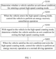
- FIG. 1 is a schematic flowchart of an energy recovery control method for a vehicle according to an example of the disclosure. As shown in FIG. 1 , the energy recovery control method may include the following steps: Step S100, whether the vehicle satisfies an activation condition for entering a preset high-speed coasting mode is determined.
- the high-speed coasting mode is used to show a working condition in which the speed of the vehicle is greater than or equal to a preset first speed threshold and the driver does not have an obvious braking requirement. For example, when the speed of the vehicle is greater than or equal to 52 km/h, it is determined that the vehicle is in a high-speed state, and the driver does not brake, but just releases an accelerator pedal, which indicates that the driver may have no obvious braking requirement, and the corresponding working condition can be set as the high-speed coasting mode. In the high-speed coasting mode, energy recovery is not suitable.
- the activation condition for the high-speed coasting mode in this example of the disclosure is configured to include the following four:
- the engine needs to be kept starting to realize the cooling function on the vehicle, and the high-speed coasting mode in the example of the disclosure requires that the engine is not started. Therefore, it is necessary to determine whether the cooling mechanism (mainly an air conditioner) of the vehicle is in a state that the engine does not need to be kept starting. For example, when the air conditioner is not turned on or the difference between the set temperature and the ambient temperature after the air conditioner is turned on is less than a preset lower temperature (for example, 7°C), it can be determined that the cooling mechanism is in the state that the engine does not need to be kept starting.
- a preset lower temperature for example, 7°C
- the activation condition further includes any one or more of the following:
- the current driving mode of the vehicle is an economical driving mode (Ecology, Conservation and Optimization, abbreviated as ECO).
- the engine When the vehicle is in the ECO mode, the engine usually does not need to be started. When the vehicle is in other driving modes other than the ECO mode, such as a sports driving mode, the engine usually needs to maintain a certain speed to improve the dynamic response capability of the vehicle.
- condition 6 usually does not occur and is mainly for the scenario where the vehicle encounters an accident and breaks down.
- Step S200 the vehicle is controlled to perform an energy recovery cancellation operation when the vehicle enters the high-speed coasting mode.
- the example of the disclosure sets a high-speed coasting mode in which the driver does not have an obvious braking requirement and energy recovery is not required. Then in step S200, when the vehicle enters the high-speed coasting mode, the vehicle is controlled to perform an energy recovery cancellation operation, to avoid energy loss caused by blindly entering the energy recovery process. More energy is lost mainly due to the losses of mechanical transmission and chemical conversion during energy conversion from kinetic energy to electrical energy.
- controlling the vehicle to perform an energy recovery cancellation operation in step S200 may include: a clutch of the vehicle is controlled to open; and the engine of the vehicle is controlled to cut off fuel and stop.
- the engine is disconnected from a drive system by opening the clutch, that is, a power system is disconnected, which is beneficial to reducing the mechanical loss of the power system.
- the operation of stopping fuel injection is beneficial to reducing fuel consumption.
- the energy recovery control method for a vehicle considers energy recovery management from the perspective of driver's driving intention, and in the high-speed coasting mode, it is recognized that the current driver does not have a strong braking intention, thereby achieving better driving intention recognition; operations such as canceling energy recovery (and/or opening the clutch, and cutting off engine oil) are performed to reduce the load, thereby reducing fuel consumption; and the vehicle is kept in a coasting state to improve vehicle coasting comfort.
- the energy recovery control method for a vehicle according to the example of the disclosure further includes step S300 and step S400 as follows.
- Step S300 for the vehicle in the high-speed coasting mode, whether the vehicle satisfies an exit condition for exiting the high-speed coasting mode is determined.
- the example of the disclosure further sets the exit condition for determining whether the vehicle exits the high-speed coasting mode.
- the exit condition may be any one of the following three condition:
- the first speed threshold is, for example, 52 km/h.
- the second speed threshold is, for example, 42 km/h.
- the opening threshold is, for example, 5% of the full opening of the accelerator pedal. All of the thresholds are TBD.
- the fifth exit condition and the sixth exit condition correspond to the activation conditions 4) and 6) mentioned above.
- the vehicle control strategy for exiting the high-speed coasting mode may be different, which will be described in detail below.
- Step S400 the vehicle is controlled to perform an energy recovery operation or a normal driving operation when the vehicle satisfies the exit condition and exits the high-speed coasting mode.
- the accelerator pedal is in a released state with an opening less than or equal to the preset opening threshold in both the first exit condition and the second exit condition, while the accelerator pedal is in a depressed state with an opening greater than the opening threshold in the third exit condition, so it can be inferred that when the third exit condition is satisfied, the driver has an acceleration intention.
- the acceleration process needs to meet normal operation of normal driving, so the energy recovery is not suitable.
- the vehicle is controlled to perform the energy recovery operation when the vehicle satisfies the first exit condition and the second exit condition, and the vehicle is controlled to perform the normal driving operation when the vehicle satisfies the third exit condition.
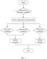
- FIG. 2 is a schematic flowchart of vehicle control according to different exit conditions according to an example of the disclosure.
- the operation of controlling the vehicle to perform the energy recovery includes: the BSG is requested to start through a Hybrid Vehicle Control Unit (HCU), an engine speed of the vehicle is controlled to increase to achieve a target speed range for implementing clutch engagement, the engine is controlled to be in a fuel cut-off state during the speed increase process, and the energy recovery process of the BSG is entered after the clutch engagement is completed.
- HCU Hybrid Vehicle Control Unit
- the controlling an engine speed of the vehicle to increase to achieve a target speed range for implementing clutch engagement includes: the engine speed is controlled to increase to a requested speed of a TCU (Transmission Control Unit), and when the speed reaches within 100n from the target speed, the clutch is engaged to enter the energy recovery process of the BSG.
- n represents a preset speed, which is TBD.
- the clutch being engaged to enter the energy recovery process of the BSG may include: the clutch first starts to slip and engage, then synchronizes through torque transmission, and finally fully engages; and after the clutch engagement is completed, the kinetic energy generated by the coasting of the vehicle is transmitted to the BSG through the vehicle-front axle-clutch-engine-BSG, and the energy recovery process of the BSG is entered.
- the controlling the vehicle to perform the energy recovery operation is similar to that of the first exit condition, so details are not described herein again. It should be noted that when the vehicle is in the high-speed coasting mode, if a series of operations such as opening the clutch and cutting off engine oil are performed while the energy recovery is canceled, the losses of energy conversion and kinetic energy can be reduced after exiting the high-speed coasting mode, and the endurance mileage can be quickly increased by energy recovery.
- the controlling the vehicle to perform the normal driving operation may include: the BSG is requested to start through the HCU, the engine is started to start fuel injection, the engine speed is controlled to increase to achieve the target speed range for implementing clutch engagement, and the normal driving process of the BSG is entered after the clutch engagement is completed.
- the process of clutch engagement is similar to the situations corresponding to the first exit condition and the second exit condition, but after the clutch engagement is completed, the kinetic energy generated by the engine is transmitted through the engine-clutch-front axle-vehicle, and then the normal driving process is entered.
- the energy recovery control method for a vehicle not only defines the high-speed coasting mode for canceling the energy recovery, but also restores the energy recovery function of the vehicle after it is recognized that the vehicle exits the high-speed coasting mode, thereby increasing the endurance mileage.
- an energy recovery control device for a vehicle.
- the energy recovery control device includes a controller, and the controller executes the energy recovery control method described in the above example.
- the controller may be, for example, an HCU, which may be used to run a program, and when the program is run, the energy recovery control method described in the above example is executed.
- an energy recovery control device for a vehicle, including: one or more processors; and a memory for storing one or more programs, the one or more programs, when executed by the one or more processors, causing the one or more processors to implement the energy recovery control method according to any one of claims 1 to 6.
- a machine-readable storage medium storing instructions that cause a machine to execute the energy recovery control method described in the above example.
- An example of the disclosure further provides a processor for running a program, and when the program is run, the energy recovery control method described in the above example is executed.
- An example of the disclosure further provides a computer program product, which, when executed on a vehicle-related component, is adapted to execute a program initialized with the following method steps: the energy recovery control method described in the above example.
- the examples of the disclosure may be provided as a method, an apparatus or a computer program product. Therefore, the disclosure may be in the form of a full hardware example, a full software example, or an example combining software and hardware. In addition, the disclosure may be in the form of a computer program product implemented on one or more computer available storage media (including but not limited to a disk memory, a CD-ROM, an optical memory, etc.) including computer available program codes.
- a computer available storage media including but not limited to a disk memory, a CD-ROM, an optical memory, etc.
- These computer program instructions can also be stored in a computer-readable memory that can guide a computer or other programmable data processing device to work in a specific manner, so that the instructions stored in the computer-readable memory generate a product including an instruction device, where the instruction device implements functions specified in one or more processes in the flowcharts and/or one or more blocks in the block diagrams.
- These computer program instructions may also be loaded into a computer or another programmable data processing device, so that a series of operation steps are performed on the computer or another programmable data processing device to generate processing implemented by a computer, and instructions executed on the computer or another programmable data processing device provide steps for implementing functions specified in one or more processes in the flowcharts and/or one or more blocks in the block diagrams.
- the computing device includes one or more central processing units (CPUs), an input/output interface, a network interface, and a memory.
- CPUs central processing units
- input/output interface input/output interface
- network interface network interface
- memory a memory
- the memory may be in the form of a volatile memory, a random access memory (RAM) and/or a non-volatile memory, such as a read-only memory (ROM) or a flash RAM, in a computer-readable medium.
- RAM random access memory
- ROM read-only memory
- flash RAM flash RAM
- the computer-readable medium can store information by any method or technology.
- the information can be computer-readable instructions, data structures, modules of programs or other data.
- Examples of the computer storage medium include, but are not limited to, a phase change memory (PRAM), a static random access memory (SRAM), a dynamic random access memory (DRAM), other type of random access memory (RAM), a read-only memory (ROM), an electrically erasable programmable read-only memory (EEPROM), a flash memory or other memory technology, a read-only disk read-only memory (CD-ROM), a digital versatile disc (DVD) or other optical storage, a magnetic cartridge tape, a tape disk storage or other magnetic storage device or any other non-transportable media, which can be used to store information that can be accessed by a computing device.
- PRAM phase change memory
- SRAM static random access memory
- DRAM dynamic random access memory
- RAM random access memory
- ROM read-only memory
- EEPROM electrically erasable programmable read-only memory
Landscapes
- Engineering & Computer Science (AREA)
- Transportation (AREA)
- Mechanical Engineering (AREA)
- Power Engineering (AREA)
- Chemical & Material Sciences (AREA)
- Combustion & Propulsion (AREA)
- Automation & Control Theory (AREA)
- Electric Propulsion And Braking For Vehicles (AREA)
- Control Of Driving Devices And Active Controlling Of Vehicle (AREA)
- Hybrid Electric Vehicles (AREA)
Description
- The present application claims priority to
Chinese Patent Application No. 201911022151.6 filed on October 25, 2019 - The disclosure relates to the technical field of vehicles, in particular to an energy recovery control method and device for a vehicle.
- At present, in the technical field of vehicles, due to the advantages of energy recovery in increasing the endurance mileage, more and more studies are blindly pursuing energy recovery as much as possible without affecting the driving experience. For example, for a 48V mild-hybrid vehicle, the use of BSG (Belt-driven Starter Generator) for energy recovery during braking or coasting can significantly increase the endurance mileage. However, taking the BSG as an example, current energy recovery scenarios are too simple. Generally, only the release of an accelerator pedal or the depression of a brake pedal is used as the activation condition of energy recovery. However, in some driving scenarios, such as when the vehicle is coasting by releasing the accelerator pedal at a high speed, the driver's braking intention is not strong, the deceleration provided by energy recovery is not required, and the energy recovery is performed blindly, so more energy is lost due to the losses of mechanical transmission and chemical conversion during energy conversion from kinetic energy to electrical energy.
CN 110 239 507 A discloses an energy recovery control method for a hybrid vehicle, wherein the energy recovery control method comprises: determining whether the vehicle satisfies an activation condition for entering a preset high-speed coasting mode, wherein the high-speed coasting mode is used to show a working condition in which the speed of the vehicle is greater than or equal to a preset first speed threshold and the driver does not have an obvious braking requirement, and controlling the vehicle to perform an energy recovery cancellation operation when the vehicle enters the high-speed coasting mode. - In view of this, the present disclosure aims to provide an energy recovery control method for a vehicle to at least partially solve the above technical problems.
- In order to achieve the above objective, the technical solution of the disclosure at least comprise the features of claim 1. According to the present invention it is implemented as follows:
- An energy recovery control method for a vehicle includes: determining whether the vehicle satisfies an activation condition for entering a preset high-speed coasting mode, the high-speed coasting mode being used to show a working condition in which the speed of the vehicle is greater than or equal to a preset first speed threshold and the driver does not have an obvious braking requirement; and controlling the vehicle to perform an energy recovery cancellation operation when the vehicle enters the high-speed coasting mode.
- Further, the activation condition is configured to include the following: the speed of the vehicle is greater than or equal to the preset first speed threshold; an accelerator pedal opening of the vehicle is less than or equal to a preset opening threshold; a brake pedal of the vehicle is in a non-depressed state; and a cooling mechanism of the vehicle is in a state that an engine does not need to be kept starting.
- Further, the activation condition further includes any one or more of the following: the current driving mode of the vehicle is an economical driving mode; and the vehicle currently has not received an engine stop prohibition instruction or engine failure information.
- Further, the controlling the vehicle to perform an energy recovery cancellation operation includes: controlling a clutch of the vehicle to open; and controlling the engine of the vehicle to cut off fuel and stop.
- Further, the energy recovery control method further includes: for the vehicle in the high-speed coasting mode, determining whether the vehicle satisfies an exit condition for exiting the high-speed coasting mode; and, controlling the vehicle to perform an energy recovery operation or a normal driving operation when the vehicle satisfies the exit condition and exits the high-speed coasting mode.
- Further, the exit condition includes any one of the following:
- a first exit condition, configured to include: the speed of the vehicle is less than a preset second speed threshold;
- a second exit condition, configured to include: the accelerator pedal opening of the vehicle is less than or equal to the preset opening threshold and the brake pedal of the vehicle is in a depressed state;
- a third exit condition, configured to include: the accelerator pedal opening of the vehicle is greater than the preset opening threshold and the brake pedal of the vehicle is in the non-depressed state;
- a fourth exit condition, configured to include: the speed of the vehicle is less than the preset second speed threshold, and the accelerator pedal opening of the vehicle is less than or equal to the preset opening threshold and/or the brake pedal of the vehicle is in the non-depressed state, the second speed threshold being less than the first speed threshold;
- a fifth exit condition, configured to include: the vehicle currently has received the engine stop prohibition instruction or engine failure information; and
- a sixth exit condition, configured to include: the cooling mechanism of the vehicle is in the state that the engine does not need to be kept starting.
- Further, the controlling the vehicle to perform an energy recovery operation or a normal driving operation includes: controlling the vehicle to perform the energy recovery operation when the vehicle satisfies the first exit condition and the second exit condition; and controlling the vehicle to perform the normal driving operation when the vehicle satisfies the third exit condition.
- Further, the controlling the vehicle to perform the energy recovery operation includes: for the vehicle with a BSG, requesting the BSG to start through a hybrid vehicle control unit (HCU), controlling an engine speed of the vehicle to increase to achieve a target speed range for implementing clutch engagement, controlling the engine to be in a fuel cut-off state during the speed increase process, and entering the energy recovery process of the BSG after the clutch engagement is completed; and/or the controlling the vehicle to perform the normal driving operation includes: for the vehicle with the BSG, requesting the BSG to start through the HCU, starting the engine to start fuel injection, controlling the engine speed to increase to achieve the target speed range for implementing clutch engagement, and entering the normal driving process of the BSG after the clutch engagement is completed.
- Compared with the prior art, the energy recovery method for a vehicle according to the disclosure has the following advantages: energy recovery management can be considered from the perspective of driver's driving intention; and in the high-speed coasting mode, it is recognized that that the driver currently does not have a strong braking intention, and energy recovery is cancelled, thereby reducing fuel consumption, achieving better driver intention recognition, and improving vehicle coasting comfort.
- Another objective of the disclosure is to provide an energy recovery control device for a vehicle to at least partially solve the above technical problems.
- In order to achieve the above objective, the technical solution of the disclosure is implemented as follows:
An energy recovery control device for a vehicle includes a controller, the controller executing the above-mentioned energy recovery control method. - An energy recovery control device for a vehicle includes: one or more processors; a memory for storing one or more programs, the one or more programs, when executed by the one or more processors, causing the one or more processors to implement the energy recovery control method as described above.
- Another objective of the disclosure is to provide a machine-readable storage medium and a processor to at least partially solve the above technical problems.
- In order to achieve the above objective, the technical solution of the disclosure is implemented as follows:
A machine-readable storage medium stores instructions that cause a machine to execute the above-mentioned energy recovery control method. - A processor for running a program, when the program is run, the energy recovery control method as described above is executed.
- The energy recovery control device for a vehicle, the machine-readable storage medium and the processor have the same advantages as the above-mentioned energy recovery control method for a vehicle over the prior art, which will not be repeated here.
- Other features and advantages of the disclosure will be described in detail in specific embodiments below.
- The accompanying drawings constituting a part of the disclosure are used for providing a further understanding of the disclosure, and the schematic embodiments of the disclosure and the descriptions thereof are used for interpreting the disclosure, rather than constituting improper limitations to the disclosure. In the drawings:
-
FIG. 1 is a flowchart of an energy recovery control method for a vehicle according to an example of the disclosure; and -
FIG. 2 is a flowchart of vehicle control according to different exit conditions according to an example of the disclosure. - It should be noted that the embodiments of the disclosure and the features of the embodiments may be combined with each other without conflict.
- The disclosure will be described in detail below with reference to the accompanying drawings and in conjunction with examples.
-
FIG. 1 is a schematic flowchart of an energy recovery control method for a vehicle according to an example of the disclosure. As shown inFIG. 1 , the energy recovery control method may include the following steps:
Step S100, whether the vehicle satisfies an activation condition for entering a preset high-speed coasting mode is determined. - The high-speed coasting mode is used to show a working condition in which the speed of the vehicle is greater than or equal to a preset first speed threshold and the driver does not have an obvious braking requirement. For example, when the speed of the vehicle is greater than or equal to 52 km/h, it is determined that the vehicle is in a high-speed state, and the driver does not brake, but just releases an accelerator pedal, which indicates that the driver may have no obvious braking requirement, and the corresponding working condition can be set as the high-speed coasting mode. In the high-speed coasting mode, energy recovery is not suitable.
- According to the invention, the activation condition for the high-speed coasting mode in this example of the disclosure is configured to include the following four:
- 1) The speed of the vehicle is greater than or equal to the preset first speed threshold.
The first speed threshold is a value To Be Determined (TBD). For example, the first speed threshold may be 52 km/h, and once the speed of the vehicle reaches or exceeds 52 km/h, it may be considered that the vehicle is in a high-speed state. - 2) An accelerator pedal opening of the vehicle is less than or equal to a preset opening threshold.
The opening threshold is also TBD, and preferably a smaller value, such as 5% of the maximum opening. When the accelerator pedal opening is less than or equal to 5%, it may be considered that the driver has loosened or released the accelerator pedal. - 3) A brake pedal of the vehicle is in a non-depressed state.
The brake pedal being in a non-depressed state indicates that the driver does not have a braking intention. - 4) A cooling mechanism of the vehicle is in a state that an engine does not need to be kept starting.
- It should be noted that the engine needs to be kept starting to realize the cooling function on the vehicle, and the high-speed coasting mode in the example of the disclosure requires that the engine is not started. Therefore, it is necessary to determine whether the cooling mechanism (mainly an air conditioner) of the vehicle is in a state that the engine does not need to be kept starting. For example, when the air conditioner is not turned on or the difference between the set temperature and the ambient temperature after the air conditioner is turned on is less than a preset lower temperature (for example, 7°C), it can be determined that the cooling mechanism is in the state that the engine does not need to be kept starting.
- By detecting the above four conditions, the accuracy of determining whether the vehicle has entered the preset high-speed coasting mode can be ensured. However, there are also some special working conditions in actual driving, for example, the engine of the vehicle fails or the vehicle is in a driving mode that the engine needs to be started. In this regard, in a more preferred example, in addition to the above four conditions, the activation condition further includes any one or more of the following:
- 5) The current driving mode of the vehicle is an economical driving mode (Ecology, Conservation and Optimization, abbreviated as ECO).
- When the vehicle is in the ECO mode, the engine usually does not need to be started. When the vehicle is in other driving modes other than the ECO mode, such as a sports driving mode, the engine usually needs to maintain a certain speed to improve the dynamic response capability of the vehicle.
- 6) The vehicle currently has not received an engine stop prohibition instruction or engine failure information.
- It should be noted that the condition 6) usually does not occur and is mainly for the scenario where the vehicle encounters an accident and breaks down.
- Step S200, the vehicle is controlled to perform an energy recovery cancellation operation when the vehicle enters the high-speed coasting mode.
- The example of the disclosure sets a high-speed coasting mode in which the driver does not have an obvious braking requirement and energy recovery is not required. Then in step S200, when the vehicle enters the high-speed coasting mode, the vehicle is controlled to perform an energy recovery cancellation operation, to avoid energy loss caused by blindly entering the energy recovery process. More energy is lost mainly due to the losses of mechanical transmission and chemical conversion during energy conversion from kinetic energy to electrical energy.
- Further, controlling the vehicle to perform an energy recovery cancellation operation in step S200 may include: a clutch of the vehicle is controlled to open; and the engine of the vehicle is controlled to cut off fuel and stop.
- Here, the engine is disconnected from a drive system by opening the clutch, that is, a power system is disconnected, which is beneficial to reducing the mechanical loss of the power system. In addition, the operation of stopping fuel injection is beneficial to reducing fuel consumption.
- Accordingly, the energy recovery control method for a vehicle according to the example of the disclosure considers energy recovery management from the perspective of driver's driving intention, and in the high-speed coasting mode, it is recognized that the current driver does not have a strong braking intention, thereby achieving better driving intention recognition; operations such as canceling energy recovery (and/or opening the clutch, and cutting off engine oil) are performed to reduce the load, thereby reducing fuel consumption; and the vehicle is kept in a coasting state to improve vehicle coasting comfort.
- In an example, the energy recovery control method for a vehicle according to the example of the disclosure further includes step S300 and step S400 as follows.
- Step S300, for the vehicle in the high-speed coasting mode, whether the vehicle satisfies an exit condition for exiting the high-speed coasting mode is determined.
- Once the vehicle no longer meets the requirements of the high-speed coasting mode, it should be considered to restore the energy recovery function to further improve the endurance mileage. Accordingly, the example of the disclosure further sets the exit condition for determining whether the vehicle exits the high-speed coasting mode.
- Preferably, according to the running situation of the vehicle, the exit condition may be any one of the following three condition:
- 1) A first exit condition, configured to include: the speed of the vehicle is less than a preset second speed threshold.
- 2) A second exit condition, configured to include: the accelerator pedal opening of the vehicle is less than or equal to the preset opening threshold and the brake pedal of the vehicle is in a depressed state.
- 3) A third exit condition, configured to include: the accelerator pedal opening of the vehicle is greater than the preset opening threshold and the brake pedal of the vehicle is in the non-depressed state.
- 4) A fourth exit condition, configured to include: the speed of the vehicle is less than the preset second speed threshold, and the accelerator pedal opening of the vehicle is less than or equal to the preset opening threshold and/or the brake pedal of the vehicle is in the non-depressed state, the second speed threshold being less than the first speed threshold. On the basis of the first exit condition, two determination conditions regarding the accelerator pedal opening and the depression state of the brake pedal are added to the fourth exit condition.
- 5) A fifth exit condition, configured to include: the vehicle currently has received the engine stop prohibition instruction or engine failure information.
- 6) A sixth exit condition, configured to include: the cooling mechanism of the vehicle is in the state that the engine does not need to be kept starting.
- The first speed threshold is, for example, 52 km/h. The second speed threshold is, for example, 42 km/h. The opening threshold is, for example, 5% of the full opening of the accelerator pedal. All of the thresholds are TBD. The fifth exit condition and the sixth exit condition correspond to the activation conditions 4) and 6) mentioned above.
- According to different exit conditions, the vehicle control strategy for exiting the high-speed coasting mode may be different, which will be described in detail below.
- Step S400, the vehicle is controlled to perform an energy recovery operation or a normal driving operation when the vehicle satisfies the exit condition and exits the high-speed coasting mode.
- It can be seen that the accelerator pedal is in a released state with an opening less than or equal to the preset opening threshold in both the first exit condition and the second exit condition, while the accelerator pedal is in a depressed state with an opening greater than the opening threshold in the third exit condition, so it can be inferred that when the third exit condition is satisfied, the driver has an acceleration intention. The acceleration process needs to meet normal operation of normal driving, so the energy recovery is not suitable.
- Therefore, the vehicle is controlled to perform the energy recovery operation when the vehicle satisfies the first exit condition and the second exit condition, and the vehicle is controlled to perform the normal driving operation when the vehicle satisfies the third exit condition.
- Specifically, taking the vehicle with a BSG as an example,
FIG. 2 is a schematic flowchart of vehicle control according to different exit conditions according to an example of the disclosure. - As shown in
FIG. 2 , for the first exit condition, it indicates that both the brake pedal and the accelerator pedal are in a released state, so the operation of controlling the vehicle to perform the energy recovery includes: the BSG is requested to start through a Hybrid Vehicle Control Unit (HCU), an engine speed of the vehicle is controlled to increase to achieve a target speed range for implementing clutch engagement, the engine is controlled to be in a fuel cut-off state during the speed increase process, and the energy recovery process of the BSG is entered after the clutch engagement is completed. - For example, the controlling an engine speed of the vehicle to increase to achieve a target speed range for implementing clutch engagement includes: the engine speed is controlled to increase to a requested speed of a TCU (Transmission Control Unit), and when the speed reaches within 100n from the target speed, the clutch is engaged to enter the energy recovery process of the BSG. Where n represents a preset speed, which is TBD.
- Further, for example, the clutch being engaged to enter the energy recovery process of the BSG may include: the clutch first starts to slip and engage, then synchronizes through torque transmission, and finally fully engages; and after the clutch engagement is completed, the kinetic energy generated by the coasting of the vehicle is transmitted to the BSG through the vehicle-front axle-clutch-engine-BSG, and the energy recovery process of the BSG is entered.
- With regard to the second exit condition, it indicates that the accelerator pedal is always in a released state and the brake pedal is depressed, the controlling the vehicle to perform the energy recovery operation is similar to that of the first exit condition, so details are not described herein again. It should be noted that when the vehicle is in the high-speed coasting mode, if a series of operations such as opening the clutch and cutting off engine oil are performed while the energy recovery is canceled, the losses of energy conversion and kinetic energy can be reduced after exiting the high-speed coasting mode, and the endurance mileage can be quickly increased by energy recovery.
- With regard to the third exit condition, it indicates that the brake pedal is always in a released state and the accelerator pedal is depressed, the controlling the vehicle to perform the normal driving operation may include: the BSG is requested to start through the HCU, the engine is started to start fuel injection, the engine speed is controlled to increase to achieve the target speed range for implementing clutch engagement, and the normal driving process of the BSG is entered after the clutch engagement is completed. The process of clutch engagement is similar to the situations corresponding to the first exit condition and the second exit condition, but after the clutch engagement is completed, the kinetic energy generated by the engine is transmitted through the engine-clutch-front axle-vehicle, and then the normal driving process is entered.
- To sum up, the energy recovery control method for a vehicle according to the example of the disclosure not only defines the high-speed coasting mode for canceling the energy recovery, but also restores the energy recovery function of the vehicle after it is recognized that the vehicle exits the high-speed coasting mode, thereby increasing the endurance mileage.
- According to the invention there is provided an energy recovery control device for a vehicle. The energy recovery control device includes a controller, and the controller executes the energy recovery control method described in the above example. The controller may be, for example, an HCU, which may be used to run a program, and when the program is run, the energy recovery control method described in the above example is executed.
- According to the invention there is provided an energy recovery control device for a vehicle, including: one or more processors; and a memory for storing one or more programs, the one or more programs, when executed by the one or more processors, causing the one or more processors to implement the energy recovery control method according to any one of claims 1 to 6.
- According to the invention there is provided a machine-readable storage medium, storing instructions that cause a machine to execute the energy recovery control method described in the above example.
- An example of the disclosure further provides a processor for running a program, and when the program is run, the energy recovery control method described in the above example is executed. An example of the disclosure further provides a computer program product, which, when executed on a vehicle-related component, is adapted to execute a program initialized with the following method steps: the energy recovery control method described in the above example.
- It should be appreciated by those skilled in the art that the examples of the disclosure may be provided as a method, an apparatus or a computer program product. Therefore, the disclosure may be in the form of a full hardware example, a full software example, or an example combining software and hardware. In addition, the disclosure may be in the form of a computer program product implemented on one or more computer available storage media (including but not limited to a disk memory, a CD-ROM, an optical memory, etc.) including computer available program codes.
- The disclosure is described with reference to flowcharts and/or block diagrams of the method, equipment (system), and the computer program product in the examples of the disclosure. It should be understood that computer program instructions can implement each process and/or block in the flowcharts and/or block diagrams and a combination of processes and/or blocks in the flowcharts and/or block diagrams. These computer program instructions may be provided to a general-purpose computer, a dedicated computer, an embedded processor, or a processor of other programmable data processing device to generate a machine, so that a device configured to implement functions specified in one or more processes in the flowcharts and/or one or more blocks in the block diagrams is generated by using instructions executed by the general-purpose computer or the processor of other programmable data processing device.
- These computer program instructions can also be stored in a computer-readable memory that can guide a computer or other programmable data processing device to work in a specific manner, so that the instructions stored in the computer-readable memory generate a product including an instruction device, where the instruction device implements functions specified in one or more processes in the flowcharts and/or one or more blocks in the block diagrams.
- These computer program instructions may also be loaded into a computer or another programmable data processing device, so that a series of operation steps are performed on the computer or another programmable data processing device to generate processing implemented by a computer, and instructions executed on the computer or another programmable data processing device provide steps for implementing functions specified in one or more processes in the flowcharts and/or one or more blocks in the block diagrams.
- In a typical configuration, the computing device includes one or more central processing units (CPUs), an input/output interface, a network interface, and a memory.
- The memory may be in the form of a volatile memory, a random access memory (RAM) and/or a non-volatile memory, such as a read-only memory (ROM) or a flash RAM, in a computer-readable medium. The memory is an example of the computer-readable medium.
- The computer-readable medium, including permanent and non-permanent, mobile and immobile media, can store information by any method or technology. The information can be computer-readable instructions, data structures, modules of programs or other data. Examples of the computer storage medium include, but are not limited to, a phase change memory (PRAM), a static random access memory (SRAM), a dynamic random access memory (DRAM), other type of random access memory (RAM), a read-only memory (ROM), an electrically erasable programmable read-only memory (EEPROM), a flash memory or other memory technology, a read-only disk read-only memory (CD-ROM), a digital versatile disc (DVD) or other optical storage, a magnetic cartridge tape, a tape disk storage or other magnetic storage device or any other non-transportable media, which can be used to store information that can be accessed by a computing device.
- It should also be noted that the terms "include" or any variants thereof are intended to cover a non-exclusive inclusion. As such, a process, method, commodity, or device including a series of elements not only includes these elements, but further includes other elements not definitely listed, or can include inherent elements of the process, method, commodity, or device. In the absence of more limitations, an element limited by "include a..." does not exclude other same elements existing in the process, method, commodity, or device including the element.
Claims (9)
- An energy recovery control method for a hybrid vehicle, wherein the energy recovery control method comprises:determining whether the vehicle satisfies an activation condition for entering a preset high-speed coasting mode, (S100) wherein the high-speed coasting mode is used to show a working condition in which the speed of the vehicle is greater than or equal to a preset first speed threshold and the driver does not have an obvious braking requirement, wherein an obvious braking requirement is when the vehicle is in a high-speed state, and the driver does not brake, but just releases an accelerator pedal; andcontrolling the vehicle to perform an energy recovery cancellation operation when the vehicle enters the high-speed coasting mode, (S200) whereinthe activation condition is configured to comprise the following:the speed of the vehicle is greater than or equal to the first speed threshold;an accelerator pedal opening of the vehicle is less than or equal to a preset opening threshold;a brake pedal of the vehicle is in a non-depressed state; and characterized in that the activation condition is configured to further comprise:a cooling mechanism of the vehicle is in a state that an engine of the vehicle does not need to be kept starting, which is when the air conditioner comprised in the cooling mechanism is not turned on or the difference between the set temperature and the ambient temperature after the air conditioner is turned on is less than a preset lower temperature,wherein the activation condition further comprises any one or more of the following:the current driving mode of the vehicle is an economical driving mode; andthe vehicle currently has not received an engine stop prohibition instruction or engine failure information for the engine of the vehicle.
- The energy recovery control method for a vehicle according to claim 1, wherein the controlling the vehicle to perform an energy recovery cancellation operation comprises:controlling a clutch of the vehicle to open so that the engine of the vehicle is disconnected from a drive system of the vehicle; andcontrolling the engine of the vehicle to cut off fuel and stop.
- The energy recovery control method for a vehicle according to claim 1, wherein the energy recovery control method further comprises:for the vehicle in the high-speed coasting mode, determining whether the vehicle satisfies an exit condition for exiting the high-speed coasting mode; (S300) andcontrolling the vehicle to perform an energy recovery operation or a normal driving operation when the vehicle satisfies the exit condition and exits the high-speed coasting mode (S400).
- The energy recovery control method for a vehicle according to claim 3, wherein the exit condition comprises any one of the following:a first exit condition, configured to comprise: the speed of the vehicle is less than a preset second speed threshold, wherein the second speed threshold is less than the first speed threshold;a second exit condition, configured to comprise: the accelerator pedal opening of the vehicle is less than or equal to the preset opening threshold and the brake pedal of the vehicle is in a depressed state;a third exit condition, configured to comprise: the accelerator pedal opening of the vehicle is greater than the preset opening threshold and the brake pedal of the vehicle is in the non-depressed state;a fourth exit condition, configured to comprise: the speed of the vehicle is less than the preset second speed threshold, and the accelerator pedal opening of the vehicle is less than or equal to the preset opening threshold and/or the brake pedal of the vehicle is in the non-depressed state, wherein the second speed threshold is less than the first speed threshold;a fifth exit condition, configured to comprise: the vehicle currently has received the engine stop prohibition instruction or engine failure information; and a sixth exit condition, configured to comprise: the cooling mechanism of the vehicle is in the state that the engine does not need to be kept starting.
- The energy recovery control method for a vehicle according to claim 4, wherein the controlling the vehicle to perform an energy recovery operation or a normal driving operation comprises:controlling the vehicle to perform the energy recovery operation when the vehicle satisfies the first exit condition and the second exit condition; andcontrolling the vehicle to perform the normal driving operation when the vehicle satisfies the third exit condition.
- The energy recovery control method for a vehicle according to claim 3, wherein the vehicle comprises a Belt-driven Starter Generator (BSG) and a hybrid vehicle control unit (HCU); and
the controlling the vehicle to perform the energy recovery operation comprises:for the vehicle with the Belt-driven Starter Generator (BSG), requesting the BSG to start through the hybrid vehicle control unit (HCU), controlling an engine speed of the vehicle to increase to achieve a target speed range for implementing clutch engagement, controlling the engine to be in a fuel cut-off state during the speed increase process, and entering the energy recovery process of the BSG after the clutch engagement is completed; and/orthe controlling the vehicle to perform the normal driving operation comprises:
for the vehicle with the BSG, requesting the BSG to start through the HCU, starting the engine to start fuel injection, controlling the engine speed to increase to achieve the target speed range for implementing clutch engagement, and entering the normal driving process of the BSG after the clutch engagement is completed. - An energy recovery control device for a hybrid vehicle, wherein the energy recovery control device comprises:one or more processors; anda storage device for storing one or more programs,wherein the one or more programs, when executed by the one or more processors, cause the one or more processors to implement the energy recovery control method according to any one of claims 1 to 6.
- Energy recovery control device according to claim 7, wherein the storage device is a machine-readable storage medium, storing instructions that cause a machine to execute the energy recovery control method according to any one of claims 1 to 6.
- Energy recovery control device according to claim 7 or 8, wherein the one or more processors are each a processor for running a program, wherein when the program is run, the energy recovery control method according to any one of claims 1 to 6 is executed.
Applications Claiming Priority (2)
| Application Number | Priority Date | Filing Date | Title |
|---|---|---|---|
| CN201911022151.6A CN111634281A (en) | 2019-10-25 | 2019-10-25 | Vehicle energy recovery control method and device |
| PCT/CN2020/110695 WO2021077885A1 (en) | 2019-10-25 | 2020-08-24 | Energy recovery control method and device for vehicle |
Publications (3)
| Publication Number | Publication Date |
|---|---|
| EP4011679A1 EP4011679A1 (en) | 2022-06-15 |
| EP4011679A4 EP4011679A4 (en) | 2022-09-14 |
| EP4011679B1 true EP4011679B1 (en) | 2024-12-18 |
Family
ID=72324643
Family Applications (1)
| Application Number | Title | Priority Date | Filing Date |
|---|---|---|---|
| EP20879374.5A Active EP4011679B1 (en) | 2019-10-25 | 2020-08-24 | Energy recovery control method and device for vehicle |
Country Status (3)
| Country | Link |
|---|---|
| EP (1) | EP4011679B1 (en) |
| CN (1) | CN111634281A (en) |
| WO (1) | WO2021077885A1 (en) |
Families Citing this family (9)
| Publication number | Priority date | Publication date | Assignee | Title |
|---|---|---|---|---|
| CN113250833B (en) * | 2021-05-29 | 2022-06-10 | 奇瑞汽车股份有限公司 | Engine fuel cut-off control method for vehicle sliding stage |
| CN113147727B (en) * | 2021-06-04 | 2022-09-02 | 一汽解放青岛汽车有限公司 | Energy recovery control method for hybrid vehicle, and storage medium |
| CN115465110A (en) * | 2021-06-11 | 2022-12-13 | 格力博(江苏)股份有限公司 | Vehicle brake control method and system |
| CN114132368B (en) * | 2021-11-23 | 2022-12-20 | 交控科技股份有限公司 | Vehicle control method, device and equipment and readable storage medium |
| CN119630573A (en) * | 2022-08-19 | 2025-03-14 | 深圳引望智能技术有限公司 | Control method, device and vehicle |
| CN115431984A (en) * | 2022-09-29 | 2022-12-06 | 安徽江淮汽车集团股份有限公司 | Electric vehicle energy recovery control method, system, electronic device and storage medium |
| CN115503498B (en) * | 2022-11-04 | 2025-08-19 | 摩登汽车有限公司 | Vehicle energy recovery intensity assessment method |
| CN119308774A (en) * | 2024-10-11 | 2025-01-14 | 中国第一汽车股份有限公司 | Engine drag torque control method, device, electronic equipment and vehicle |
| CN119568157A (en) * | 2024-12-09 | 2025-03-07 | 杭叉集团股份有限公司 | Automatic deceleration control method and system for industrial vehicle |
Citations (4)
| Publication number | Priority date | Publication date | Assignee | Title |
|---|---|---|---|---|
| US8612108B2 (en) * | 2012-01-24 | 2013-12-17 | C.R.F. Societa' Consortile Per Azioni | Entering and leaving a motor vehicle freewheel running condition with internal combustion engine off |
| CN103661381A (en) * | 2012-08-29 | 2014-03-26 | 现代自动车株式会社 | Device and method for controlling driving of a vehicle in a coasting situation |
| CN110077390A (en) * | 2019-03-22 | 2019-08-02 | 中国第一汽车股份有限公司 | A kind of DCT transmission control method and system for supporting 48V energy regenerating |
| CN110239507A (en) * | 2019-05-23 | 2019-09-17 | 浙江吉利控股集团有限公司 | A kind of automobile energy management method, device and terminal |
Family Cites Families (14)
| Publication number | Priority date | Publication date | Assignee | Title |
|---|---|---|---|---|
| JP3578071B2 (en) * | 2000-09-14 | 2004-10-20 | トヨタ自動車株式会社 | Control device for variable cylinder engine and control device for vehicle |
| JP5162998B2 (en) * | 2006-10-12 | 2013-03-13 | 日産自動車株式会社 | Hybrid vehicle mode switching control device |
| CN102501850B (en) * | 2011-12-27 | 2015-09-23 | 广东戈兰玛汽车系统有限公司 | Automatic start-stop system |
| WO2014073435A1 (en) * | 2012-11-07 | 2014-05-15 | 日産自動車株式会社 | Hybrid vehicle control device |
| JP5505492B1 (en) * | 2012-11-28 | 2014-05-28 | トヨタ自動車株式会社 | Hybrid vehicle running state control device |
| EP2902292B1 (en) * | 2014-01-31 | 2019-09-04 | Ford Global Technologies, LLC | Method and system for controlling the regenerative braking of a vehicle |
| JP6573201B2 (en) * | 2014-02-20 | 2019-09-11 | パナソニックIpマネジメント株式会社 | Hybrid system for vehicles |
| JP6168031B2 (en) * | 2014-11-14 | 2017-07-26 | トヨタ自動車株式会社 | vehicle |
| DE102015206919A1 (en) * | 2015-04-16 | 2016-10-20 | Ford Global Technologies, Llc | Electric motor vehicle and operating method for an electric motor vehicle |
| US10272913B2 (en) * | 2015-06-17 | 2019-04-30 | Consortium de Recherche BRP—Universite de Sherbrooke S.E.N.C. | Regenerative braking system and method |
| KR101786666B1 (en) * | 2015-08-26 | 2017-10-18 | 현대자동차 주식회사 | Apparatus and method for controlling of vehicle having motor |
| KR20180067984A (en) * | 2016-12-13 | 2018-06-21 | 현대자동차주식회사 | Method and apparatus for controlling mhsg of mild hybrid electric vehicle |
| CN107199893B (en) * | 2017-05-27 | 2019-09-03 | 北京新能源汽车股份有限公司 | Energy recovery method and device |
| CN108544927B (en) * | 2018-03-21 | 2022-03-11 | 重庆长安汽车股份有限公司 | Automobile 48V energy recovery system and method |
-
2019
- 2019-10-25 CN CN201911022151.6A patent/CN111634281A/en active Pending
-
2020
- 2020-08-24 EP EP20879374.5A patent/EP4011679B1/en active Active
- 2020-08-24 WO PCT/CN2020/110695 patent/WO2021077885A1/en not_active Ceased
Patent Citations (4)
| Publication number | Priority date | Publication date | Assignee | Title |
|---|---|---|---|---|
| US8612108B2 (en) * | 2012-01-24 | 2013-12-17 | C.R.F. Societa' Consortile Per Azioni | Entering and leaving a motor vehicle freewheel running condition with internal combustion engine off |
| CN103661381A (en) * | 2012-08-29 | 2014-03-26 | 现代自动车株式会社 | Device and method for controlling driving of a vehicle in a coasting situation |
| CN110077390A (en) * | 2019-03-22 | 2019-08-02 | 中国第一汽车股份有限公司 | A kind of DCT transmission control method and system for supporting 48V energy regenerating |
| CN110239507A (en) * | 2019-05-23 | 2019-09-17 | 浙江吉利控股集团有限公司 | A kind of automobile energy management method, device and terminal |
Also Published As
| Publication number | Publication date |
|---|---|
| EP4011679A4 (en) | 2022-09-14 |
| WO2021077885A1 (en) | 2021-04-29 |
| EP4011679A1 (en) | 2022-06-15 |
| CN111634281A (en) | 2020-09-08 |
Similar Documents
| Publication | Publication Date | Title |
|---|---|---|
| EP4011679A1 (en) | Energy recovery control method and device for vehicle | |
| JP5935886B2 (en) | Vehicle control device | |
| US9145134B2 (en) | Method and system for controlling engine start of hybrid vehicle | |
| US10913447B2 (en) | Control method and system for clutch engagement of hybrid vehicle | |
| US9475489B2 (en) | Method and system for controlling running mode change for hybrid vehicle | |
| KR102692281B1 (en) | Motor toruqe control method for motor driven vehicle | |
| US20100304923A1 (en) | Method For Controlling A Hybrid Drive | |
| US9043117B2 (en) | Driver assistance system in a motor vehicle comprising a speed limiting function | |
| US10626836B2 (en) | Control method of idle stop and go system | |
| US10363932B2 (en) | SSC-SCC system for increasing SSC distance using SSC and method for controlling the same | |
| CN111845689B (en) | Clutch control method and device and computer readable storage medium | |
| CN110194141B (en) | Crawling control method and device, transmission and vehicle | |
| CN111894747A (en) | Hybrid vehicle engine starting control method and system and hybrid vehicle | |
| JP2016022772A (en) | Vehicle control device | |
| EP2212148B1 (en) | A method for a more efficient use of a combustion engine in a vehicle provided with an automatic step gear transmission | |
| US10352438B1 (en) | Vehicle propulsion system and method for controlling a vehicle propulsion system | |
| CN118928440A (en) | Vehicle control method, device, vehicle and storage medium | |
| CN106671968B (en) | Hybrid electric vehicle and method for efficiently controlling transmission thereof | |
| KR20240001766A (en) | Vehicle, vehicle control method and vehicle braking control method | |
| JP2014172456A (en) | Controller of idling stop car | |
| JP7544078B2 (en) | Hybrid vehicle control device | |
| CN115264057B (en) | Control method and device for vehicle, storage medium and processor | |
| US12427980B2 (en) | Vehicle control method for a stop on the move state | |
| JP4166750B2 (en) | Control device for hybrid vehicle | |
| KR20170107244A (en) | A method for controlling a velocity of vehicle in ssc entry condition and an apparatus the same |
Legal Events
| Date | Code | Title | Description |
|---|---|---|---|
| STAA | Information on the status of an ep patent application or granted ep patent |
Free format text: STATUS: THE INTERNATIONAL PUBLICATION HAS BEEN MADE |
|
| PUAI | Public reference made under article 153(3) epc to a published international application that has entered the european phase |
Free format text: ORIGINAL CODE: 0009012 |
|
| STAA | Information on the status of an ep patent application or granted ep patent |
Free format text: STATUS: REQUEST FOR EXAMINATION WAS MADE |
|
| 17P | Request for examination filed |
Effective date: 20220309 |
|
| AK | Designated contracting states |
Kind code of ref document: A1 Designated state(s): AL AT BE BG CH CY CZ DE DK EE ES FI FR GB GR HR HU IE IS IT LI LT LU LV MC MK MT NL NO PL PT RO RS SE SI SK SM TR |
|
| A4 | Supplementary search report drawn up and despatched |
Effective date: 20220816 |
|
| RIC1 | Information provided on ipc code assigned before grant |
Ipc: B60W 20/15 20160101ALI20220809BHEP Ipc: B60K 6/20 20071001ALI20220809BHEP Ipc: B60W 50/00 20060101ALI20220809BHEP Ipc: B60L 1/08 20060101ALI20220809BHEP Ipc: B60L 7/18 20060101ALI20220809BHEP Ipc: B60L 50/10 20190101ALI20220809BHEP Ipc: B60L 15/20 20060101ALI20220809BHEP Ipc: B60W 30/18 20120101ALI20220809BHEP Ipc: B60L 7/10 20060101AFI20220809BHEP |
|
| DAV | Request for validation of the european patent (deleted) | ||
| DAX | Request for extension of the european patent (deleted) | ||
| P01 | Opt-out of the competence of the unified patent court (upc) registered |
Effective date: 20230530 |
|
| STAA | Information on the status of an ep patent application or granted ep patent |
Free format text: STATUS: EXAMINATION IS IN PROGRESS |
|
| 17Q | First examination report despatched |
Effective date: 20231019 |
|
| GRAP | Despatch of communication of intention to grant a patent |
Free format text: ORIGINAL CODE: EPIDOSNIGR1 |
|
| STAA | Information on the status of an ep patent application or granted ep patent |
Free format text: STATUS: GRANT OF PATENT IS INTENDED |
|
| RIC1 | Information provided on ipc code assigned before grant |
Ipc: B60W 20/15 20160101ALI20240623BHEP Ipc: B60K 6/20 20071001ALI20240623BHEP Ipc: B60W 50/00 20060101ALI20240623BHEP Ipc: B60L 1/08 20060101ALI20240623BHEP Ipc: B60L 7/18 20060101ALI20240623BHEP Ipc: B60L 50/10 20190101ALI20240623BHEP Ipc: B60K 6/485 20071001ALI20240623BHEP Ipc: B60W 10/06 20060101ALI20240623BHEP Ipc: B60W 10/02 20060101ALI20240623BHEP Ipc: B60L 15/20 20060101ALI20240623BHEP Ipc: B60W 30/18 20120101ALI20240623BHEP Ipc: B60L 7/10 20060101AFI20240623BHEP |
|
| INTG | Intention to grant announced |
Effective date: 20240711 |
|
| GRAS | Grant fee paid |
Free format text: ORIGINAL CODE: EPIDOSNIGR3 |
|
| GRAA | (expected) grant |
Free format text: ORIGINAL CODE: 0009210 |
|
| STAA | Information on the status of an ep patent application or granted ep patent |
Free format text: STATUS: THE PATENT HAS BEEN GRANTED |
|
| AK | Designated contracting states |
Kind code of ref document: B1 Designated state(s): AL AT BE BG CH CY CZ DE DK EE ES FI FR GB GR HR HU IE IS IT LI LT LU LV MC MK MT NL NO PL PT RO RS SE SI SK SM TR |
|
| REG | Reference to a national code |
Ref country code: CH Ref legal event code: EP |
|
| REG | Reference to a national code |
Ref country code: DE Ref legal event code: R096 Ref document number: 602020043515 Country of ref document: DE |
|
| REG | Reference to a national code |
Ref country code: IE Ref legal event code: FG4D |
|
| REG | Reference to a national code |
Ref country code: LT Ref legal event code: MG9D |
|
| PG25 | Lapsed in a contracting state [announced via postgrant information from national office to epo] |
Ref country code: HR Free format text: LAPSE BECAUSE OF FAILURE TO SUBMIT A TRANSLATION OF THE DESCRIPTION OR TO PAY THE FEE WITHIN THE PRESCRIBED TIME-LIMIT Effective date: 20241218 |
|
| PG25 | Lapsed in a contracting state [announced via postgrant information from national office to epo] |
Ref country code: FI Free format text: LAPSE BECAUSE OF FAILURE TO SUBMIT A TRANSLATION OF THE DESCRIPTION OR TO PAY THE FEE WITHIN THE PRESCRIBED TIME-LIMIT Effective date: 20241218 |
|
| PG25 | Lapsed in a contracting state [announced via postgrant information from national office to epo] |
Ref country code: BG Free format text: LAPSE BECAUSE OF FAILURE TO SUBMIT A TRANSLATION OF THE DESCRIPTION OR TO PAY THE FEE WITHIN THE PRESCRIBED TIME-LIMIT Effective date: 20241218 |
|
| PG25 | Lapsed in a contracting state [announced via postgrant information from national office to epo] |
Ref country code: NO Free format text: LAPSE BECAUSE OF FAILURE TO SUBMIT A TRANSLATION OF THE DESCRIPTION OR TO PAY THE FEE WITHIN THE PRESCRIBED TIME-LIMIT Effective date: 20250318 |
|
| REG | Reference to a national code |
Ref country code: NL Ref legal event code: MP Effective date: 20241218 |
|
| PG25 | Lapsed in a contracting state [announced via postgrant information from national office to epo] |
Ref country code: LV Free format text: LAPSE BECAUSE OF FAILURE TO SUBMIT A TRANSLATION OF THE DESCRIPTION OR TO PAY THE FEE WITHIN THE PRESCRIBED TIME-LIMIT Effective date: 20241218 Ref country code: GR Free format text: LAPSE BECAUSE OF FAILURE TO SUBMIT A TRANSLATION OF THE DESCRIPTION OR TO PAY THE FEE WITHIN THE PRESCRIBED TIME-LIMIT Effective date: 20250319 |
|
| PG25 | Lapsed in a contracting state [announced via postgrant information from national office to epo] |
Ref country code: RS Free format text: LAPSE BECAUSE OF FAILURE TO SUBMIT A TRANSLATION OF THE DESCRIPTION OR TO PAY THE FEE WITHIN THE PRESCRIBED TIME-LIMIT Effective date: 20250318 |
|
| PG25 | Lapsed in a contracting state [announced via postgrant information from national office to epo] |
Ref country code: NL Free format text: LAPSE BECAUSE OF FAILURE TO SUBMIT A TRANSLATION OF THE DESCRIPTION OR TO PAY THE FEE WITHIN THE PRESCRIBED TIME-LIMIT Effective date: 20241218 |
|
| REG | Reference to a national code |
Ref country code: AT Ref legal event code: MK05 Ref document number: 1752004 Country of ref document: AT Kind code of ref document: T Effective date: 20241218 |
|
| PG25 | Lapsed in a contracting state [announced via postgrant information from national office to epo] |
Ref country code: SM Free format text: LAPSE BECAUSE OF FAILURE TO SUBMIT A TRANSLATION OF THE DESCRIPTION OR TO PAY THE FEE WITHIN THE PRESCRIBED TIME-LIMIT Effective date: 20241218 |
|
| PG25 | Lapsed in a contracting state [announced via postgrant information from national office to epo] |
Ref country code: PL Free format text: LAPSE BECAUSE OF FAILURE TO SUBMIT A TRANSLATION OF THE DESCRIPTION OR TO PAY THE FEE WITHIN THE PRESCRIBED TIME-LIMIT Effective date: 20241218 |
|
| PG25 | Lapsed in a contracting state [announced via postgrant information from national office to epo] |
Ref country code: ES Free format text: LAPSE BECAUSE OF FAILURE TO SUBMIT A TRANSLATION OF THE DESCRIPTION OR TO PAY THE FEE WITHIN THE PRESCRIBED TIME-LIMIT Effective date: 20241218 |
|
| PG25 | Lapsed in a contracting state [announced via postgrant information from national office to epo] |
Ref country code: IS Free format text: LAPSE BECAUSE OF FAILURE TO SUBMIT A TRANSLATION OF THE DESCRIPTION OR TO PAY THE FEE WITHIN THE PRESCRIBED TIME-LIMIT Effective date: 20250418 |
|
| PG25 | Lapsed in a contracting state [announced via postgrant information from national office to epo] |
Ref country code: PT Free format text: LAPSE BECAUSE OF FAILURE TO SUBMIT A TRANSLATION OF THE DESCRIPTION OR TO PAY THE FEE WITHIN THE PRESCRIBED TIME-LIMIT Effective date: 20250421 |
|
| PG25 | Lapsed in a contracting state [announced via postgrant information from national office to epo] |
Ref country code: EE Free format text: LAPSE BECAUSE OF FAILURE TO SUBMIT A TRANSLATION OF THE DESCRIPTION OR TO PAY THE FEE WITHIN THE PRESCRIBED TIME-LIMIT Effective date: 20241218 |
|
| PG25 | Lapsed in a contracting state [announced via postgrant information from national office to epo] |
Ref country code: AT Free format text: LAPSE BECAUSE OF FAILURE TO SUBMIT A TRANSLATION OF THE DESCRIPTION OR TO PAY THE FEE WITHIN THE PRESCRIBED TIME-LIMIT Effective date: 20241218 Ref country code: RO Free format text: LAPSE BECAUSE OF FAILURE TO SUBMIT A TRANSLATION OF THE DESCRIPTION OR TO PAY THE FEE WITHIN THE PRESCRIBED TIME-LIMIT Effective date: 20241218 |
|
| PG25 | Lapsed in a contracting state [announced via postgrant information from national office to epo] |
Ref country code: SK Free format text: LAPSE BECAUSE OF FAILURE TO SUBMIT A TRANSLATION OF THE DESCRIPTION OR TO PAY THE FEE WITHIN THE PRESCRIBED TIME-LIMIT Effective date: 20241218 |
|
| PG25 | Lapsed in a contracting state [announced via postgrant information from national office to epo] |
Ref country code: CZ Free format text: LAPSE BECAUSE OF FAILURE TO SUBMIT A TRANSLATION OF THE DESCRIPTION OR TO PAY THE FEE WITHIN THE PRESCRIBED TIME-LIMIT Effective date: 20241218 |
|
| PG25 | Lapsed in a contracting state [announced via postgrant information from national office to epo] |
Ref country code: IT Free format text: LAPSE BECAUSE OF FAILURE TO SUBMIT A TRANSLATION OF THE DESCRIPTION OR TO PAY THE FEE WITHIN THE PRESCRIBED TIME-LIMIT Effective date: 20241218 |
|
| PG25 | Lapsed in a contracting state [announced via postgrant information from national office to epo] |
Ref country code: SE Free format text: LAPSE BECAUSE OF FAILURE TO SUBMIT A TRANSLATION OF THE DESCRIPTION OR TO PAY THE FEE WITHIN THE PRESCRIBED TIME-LIMIT Effective date: 20241218 |
|
| REG | Reference to a national code |
Ref country code: DE Ref legal event code: R097 Ref document number: 602020043515 Country of ref document: DE |
|
| PG25 | Lapsed in a contracting state [announced via postgrant information from national office to epo] |
Ref country code: DK Free format text: LAPSE BECAUSE OF FAILURE TO SUBMIT A TRANSLATION OF THE DESCRIPTION OR TO PAY THE FEE WITHIN THE PRESCRIBED TIME-LIMIT Effective date: 20241218 |
|
| PGFP | Annual fee paid to national office [announced via postgrant information from national office to epo] |
Ref country code: DE Payment date: 20250812 Year of fee payment: 6 |
|
| PGFP | Annual fee paid to national office [announced via postgrant information from national office to epo] |
Ref country code: GB Payment date: 20250826 Year of fee payment: 6 |
|
| PGFP | Annual fee paid to national office [announced via postgrant information from national office to epo] |
Ref country code: FR Payment date: 20250828 Year of fee payment: 6 |
|
| PLBE | No opposition filed within time limit |
Free format text: ORIGINAL CODE: 0009261 |
|
| STAA | Information on the status of an ep patent application or granted ep patent |
Free format text: STATUS: NO OPPOSITION FILED WITHIN TIME LIMIT |
|
| REG | Reference to a national code |
Ref country code: CH Ref legal event code: L10 Free format text: ST27 STATUS EVENT CODE: U-0-0-L10-L00 (AS PROVIDED BY THE NATIONAL OFFICE) Effective date: 20251029 |
|
| 26N | No opposition filed |
Effective date: 20250919 |
|
| REG | Reference to a national code |
Ref country code: CH Ref legal event code: H13 Free format text: ST27 STATUS EVENT CODE: U-0-0-H10-H13 (AS PROVIDED BY THE NATIONAL OFFICE) Effective date: 20260324 |
|
| PG25 | Lapsed in a contracting state [announced via postgrant information from national office to epo] |
Ref country code: MC Free format text: LAPSE BECAUSE OF FAILURE TO SUBMIT A TRANSLATION OF THE DESCRIPTION OR TO PAY THE FEE WITHIN THE PRESCRIBED TIME-LIMIT Effective date: 20241218 |
|
| PG25 | Lapsed in a contracting state [announced via postgrant information from national office to epo] |
Ref country code: LU Free format text: LAPSE BECAUSE OF NON-PAYMENT OF DUE FEES Effective date: 20250824 |
|
| PG25 | Lapsed in a contracting state [announced via postgrant information from national office to epo] |
Ref country code: CH Free format text: LAPSE BECAUSE OF NON-PAYMENT OF DUE FEES Effective date: 20250831 |