EP2212148B1 - A method for a more efficient use of a combustion engine in a vehicle provided with an automatic step gear transmission - Google Patents
A method for a more efficient use of a combustion engine in a vehicle provided with an automatic step gear transmission Download PDFInfo
- Publication number
- EP2212148B1 EP2212148B1 EP07835146.7A EP07835146A EP2212148B1 EP 2212148 B1 EP2212148 B1 EP 2212148B1 EP 07835146 A EP07835146 A EP 07835146A EP 2212148 B1 EP2212148 B1 EP 2212148B1
- Authority
- EP
- European Patent Office
- Prior art keywords
- vehicle
- engine
- rotational speed
- engine rotational
- upshift
- Prior art date
- Legal status (The legal status is an assumption and is not a legal conclusion. Google has not performed a legal analysis and makes no representation as to the accuracy of the status listed.)
- Active
Links
- 238000000034 method Methods 0.000 title claims description 34
- 230000005540 biological transmission Effects 0.000 title claims description 9
- 238000002485 combustion reaction Methods 0.000 title claims description 8
- 238000004590 computer program Methods 0.000 claims description 13
- 230000007423 decrease Effects 0.000 claims description 8
- 230000006978 adaptation Effects 0.000 claims description 2
- 230000000977 initiatory effect Effects 0.000 claims 1
- 230000006870 function Effects 0.000 description 6
- 238000004891 communication Methods 0.000 description 4
- 239000000446 fuel Substances 0.000 description 4
- 230000008901 benefit Effects 0.000 description 3
- 230000008859 change Effects 0.000 description 3
- 238000010586 diagram Methods 0.000 description 3
- 230000001133 acceleration Effects 0.000 description 2
- 230000004913 activation Effects 0.000 description 2
- 238000004364 calculation method Methods 0.000 description 2
- 230000001419 dependent effect Effects 0.000 description 2
- 230000000881 depressing effect Effects 0.000 description 2
- 238000012876 topography Methods 0.000 description 2
- 238000013500 data storage Methods 0.000 description 1
- 230000003247 decreasing effect Effects 0.000 description 1
- XDDAORKBJWWYJS-UHFFFAOYSA-N glyphosate Chemical group OC(=O)CNCP(O)(O)=O XDDAORKBJWWYJS-UHFFFAOYSA-N 0.000 description 1
- 238000012986 modification Methods 0.000 description 1
- 230000004048 modification Effects 0.000 description 1
- 239000004065 semiconductor Substances 0.000 description 1
Images

Classifications
-
- F—MECHANICAL ENGINEERING; LIGHTING; HEATING; WEAPONS; BLASTING
- F02—COMBUSTION ENGINES; HOT-GAS OR COMBUSTION-PRODUCT ENGINE PLANTS
- F02D—CONTROLLING COMBUSTION ENGINES
- F02D31/00—Use of speed-sensing governors to control combustion engines, not otherwise provided for
- F02D31/001—Electric control of rotation speed
-
- B—PERFORMING OPERATIONS; TRANSPORTING
- B60—VEHICLES IN GENERAL
- B60W—CONJOINT CONTROL OF VEHICLE SUB-UNITS OF DIFFERENT TYPE OR DIFFERENT FUNCTION; CONTROL SYSTEMS SPECIALLY ADAPTED FOR HYBRID VEHICLES; ROAD VEHICLE DRIVE CONTROL SYSTEMS FOR PURPOSES NOT RELATED TO THE CONTROL OF A PARTICULAR SUB-UNIT
- B60W10/00—Conjoint control of vehicle sub-units of different type or different function
- B60W10/04—Conjoint control of vehicle sub-units of different type or different function including control of propulsion units
- B60W10/06—Conjoint control of vehicle sub-units of different type or different function including control of propulsion units including control of combustion engines
-
- B—PERFORMING OPERATIONS; TRANSPORTING
- B60—VEHICLES IN GENERAL
- B60W—CONJOINT CONTROL OF VEHICLE SUB-UNITS OF DIFFERENT TYPE OR DIFFERENT FUNCTION; CONTROL SYSTEMS SPECIALLY ADAPTED FOR HYBRID VEHICLES; ROAD VEHICLE DRIVE CONTROL SYSTEMS FOR PURPOSES NOT RELATED TO THE CONTROL OF A PARTICULAR SUB-UNIT
- B60W30/00—Purposes of road vehicle drive control systems not related to the control of a particular sub-unit, e.g. of systems using conjoint control of vehicle sub-units, or advanced driver assistance systems for ensuring comfort, stability and safety or drive control systems for propelling or retarding the vehicle
- B60W30/18—Propelling the vehicle
- B60W30/188—Controlling power parameters of the driveline, e.g. determining the required power
- B60W30/1882—Controlling power parameters of the driveline, e.g. determining the required power characterised by the working point of the engine, e.g. by using engine output chart
-
- B—PERFORMING OPERATIONS; TRANSPORTING
- B60—VEHICLES IN GENERAL
- B60W—CONJOINT CONTROL OF VEHICLE SUB-UNITS OF DIFFERENT TYPE OR DIFFERENT FUNCTION; CONTROL SYSTEMS SPECIALLY ADAPTED FOR HYBRID VEHICLES; ROAD VEHICLE DRIVE CONTROL SYSTEMS FOR PURPOSES NOT RELATED TO THE CONTROL OF A PARTICULAR SUB-UNIT
- B60W50/00—Details of control systems for road vehicle drive control not related to the control of a particular sub-unit, e.g. process diagnostic or vehicle driver interfaces
- B60W50/0097—Predicting future conditions
-
- B—PERFORMING OPERATIONS; TRANSPORTING
- B60—VEHICLES IN GENERAL
- B60W—CONJOINT CONTROL OF VEHICLE SUB-UNITS OF DIFFERENT TYPE OR DIFFERENT FUNCTION; CONTROL SYSTEMS SPECIALLY ADAPTED FOR HYBRID VEHICLES; ROAD VEHICLE DRIVE CONTROL SYSTEMS FOR PURPOSES NOT RELATED TO THE CONTROL OF A PARTICULAR SUB-UNIT
- B60W50/00—Details of control systems for road vehicle drive control not related to the control of a particular sub-unit, e.g. process diagnostic or vehicle driver interfaces
- B60W50/08—Interaction between the driver and the control system
- B60W50/087—Interaction between the driver and the control system where the control system corrects or modifies a request from the driver
-
- F—MECHANICAL ENGINEERING; LIGHTING; HEATING; WEAPONS; BLASTING
- F02—COMBUSTION ENGINES; HOT-GAS OR COMBUSTION-PRODUCT ENGINE PLANTS
- F02D—CONTROLLING COMBUSTION ENGINES
- F02D29/00—Controlling engines, such controlling being peculiar to the devices driven thereby, the devices being other than parts or accessories essential to engine operation, e.g. controlling of engines by signals external thereto
- F02D29/02—Controlling engines, such controlling being peculiar to the devices driven thereby, the devices being other than parts or accessories essential to engine operation, e.g. controlling of engines by signals external thereto peculiar to engines driving vehicles; peculiar to engines driving variable pitch propellers
-
- F—MECHANICAL ENGINEERING; LIGHTING; HEATING; WEAPONS; BLASTING
- F02—COMBUSTION ENGINES; HOT-GAS OR COMBUSTION-PRODUCT ENGINE PLANTS
- F02D—CONTROLLING COMBUSTION ENGINES
- F02D2200/00—Input parameters for engine control
- F02D2200/70—Input parameters for engine control said parameters being related to the vehicle exterior
- F02D2200/701—Information about vehicle position, e.g. from navigation system or GPS signal
-
- F—MECHANICAL ENGINEERING; LIGHTING; HEATING; WEAPONS; BLASTING
- F02—COMBUSTION ENGINES; HOT-GAS OR COMBUSTION-PRODUCT ENGINE PLANTS
- F02D—CONTROLLING COMBUSTION ENGINES
- F02D2250/00—Engine control related to specific problems or objectives
- F02D2250/18—Control of the engine output torque
-
- F—MECHANICAL ENGINEERING; LIGHTING; HEATING; WEAPONS; BLASTING
- F02—COMBUSTION ENGINES; HOT-GAS OR COMBUSTION-PRODUCT ENGINE PLANTS
- F02D—CONTROLLING COMBUSTION ENGINES
- F02D41/00—Electrical control of supply of combustible mixture or its constituents
- F02D41/02—Circuit arrangements for generating control signals
- F02D41/021—Introducing corrections for particular conditions exterior to the engine
- F02D41/0215—Introducing corrections for particular conditions exterior to the engine in relation with elements of the transmission
-
- F—MECHANICAL ENGINEERING; LIGHTING; HEATING; WEAPONS; BLASTING
- F16—ENGINEERING ELEMENTS AND UNITS; GENERAL MEASURES FOR PRODUCING AND MAINTAINING EFFECTIVE FUNCTIONING OF MACHINES OR INSTALLATIONS; THERMAL INSULATION IN GENERAL
- F16H—GEARING
- F16H59/00—Control inputs to control units of change-speed-, or reversing-gearings for conveying rotary motion
- F16H59/36—Inputs being a function of speed
- F16H2059/363—Rate of change of input shaft speed, e.g. of engine or motor shaft
-
- F—MECHANICAL ENGINEERING; LIGHTING; HEATING; WEAPONS; BLASTING
- F16—ENGINEERING ELEMENTS AND UNITS; GENERAL MEASURES FOR PRODUCING AND MAINTAINING EFFECTIVE FUNCTIONING OF MACHINES OR INSTALLATIONS; THERMAL INSULATION IN GENERAL
- F16H—GEARING
- F16H59/00—Control inputs to control units of change-speed-, or reversing-gearings for conveying rotary motion
- F16H59/36—Inputs being a function of speed
- F16H2059/366—Engine or motor speed
-
- F—MECHANICAL ENGINEERING; LIGHTING; HEATING; WEAPONS; BLASTING
- F16—ENGINEERING ELEMENTS AND UNITS; GENERAL MEASURES FOR PRODUCING AND MAINTAINING EFFECTIVE FUNCTIONING OF MACHINES OR INSTALLATIONS; THERMAL INSULATION IN GENERAL
- F16H—GEARING
- F16H61/00—Control functions within control units of change-speed- or reversing-gearings for conveying rotary motion ; Control of exclusively fluid gearing, friction gearing, gearings with endless flexible members or other particular types of gearing
- F16H61/16—Inhibiting or initiating shift during unfavourable conditions, e.g. preventing forward reverse shift at high vehicle speed, preventing engine over speed
- F16H2061/161—Inhibiting or initiating shift during unfavourable conditions, e.g. preventing forward reverse shift at high vehicle speed, preventing engine over speed by checking feasibility of shifts, i.e. determine if requested shift can be successfully completed and post shift values are in an acceptable range
Definitions
- the present invention relates to a method for a more efficient use of a combustion engine in a vehicle, by, during certain vehicle conditions, automatically controlling engine rotational speed in a predetermined way.
- the present invention also relates to a computer program and computer program product both to be used with a computer for executing said method.
- An alternative to the estimation, that the engine of the vehicle will not be able to accelerate the vehicle to a sufficiently high vehicle speed is to simply register that the engine rotational speed increase has stopped before reaching the right engine rotational speed for upshift. This usually leads to the engine being stuck or "hanging" at relatively high engine rotational speeds without the transmission being able to perform an upshift.
- a typical example for a heavy duty truck could be that the engine must increase its speed to above 1850 rpm to be able to after an upshift land on a rotational speed with the new gear engaged that gives the engine the possibility to produce enough torque to at least be able to maintain current vehicle speed.
- it could be necessary to increase the engine rotational speed to even higher rotational speeds, such as 1900 to 1950 rpm, before a gear upshift to the new gear is initiated.
- the efficiency of the engine is relatively low, and having the engine stuck at these relatively high engine rotational speeds contributes to an increased fuel consumption.
- JP08-295154 discloses a cruise control in a vehicle which adapts the vehicle speed (decreases it) in for example an uphill so that the engine rotational speed arrives in a more efficient working area.
- US6616575 discloses a method to control a driveline where an upshift is performed instead of remaining at a less efficient engine speed, when the engine speed remains at a less efficient rotational speed during a predetermined time.
- the object of the present invention is to control the engine rotational speed in a better way in relation to a planned upshift.
- the method according to the invention is a method for a more efficient use of a combustion engine in a vehicle during driving of said vehicle, said vehicle further comprising an automatic step geared transmission for automatic gear ratio adaptation of the gear ratio between the engine rotational speed and rotational speed of driving wheels of the vehicle.
- Said method comprises the steps of:
- the advantage with the method according to the invention is that fuel will be saved since unnecessary driving at inefficient engine rotational speeds will be decreased.
- said step of registering that the engine rotational speed stops increasing without reaching said minimum upshift engine rotational speed is performed in advance before reaching said relatively high engine rotational speed where efficiency is relatively low.
- said registering step performed in advance is done through an estimation based on present prevailing vehicle conditions.
- said estimation is based on present prevailing vehicle conditions and vehicle conditions estimated likely to occur in near future of the vehicle.
- said automatic controlling of the engine torque can only be active when a cruise control arranged in the vehicle is active. This embodiment allows the driver to have more of a full manual control when driving with the cruise control inactivated.
- said automatic controlling of the engine torque can only be active when a first vehicle driving mode is activated, which first driving mode differs from a second driving mode of said vehicle.
- This first driving mode can for example be an economy mode that can be manually selected and engaged by the driver.
- said automatic controlling of the engine torque is inactivated when a driver of the vehicle demands full power to the driving wheels.
- depressing an accelerator pedal to the floor will give a down shift and vehicle acceleration.
- said automatic controlling of the engine torque is inactivated when a predetermined vehicle condition is registered.
- This predetermined vehicle condition can for example be a decrease of vehicle travel resistance to under a predetermined level.
- the control unit will allow engine rotational speed increase to the upshift engine rotational speed.
- said automatic controlling of the engine torque is activated when said vehicle travel resistance has increased to above a second predetermined level. Said first and second level can have the same value or differ from each other.
- said automatic controlling of the engine torque is independent of if a driver of the vehicle demands maximum engine output torque or not.
- a full automation will minimize the time the engine spends in the inefficient rotational speed area.
- the vehicle is equipped with an internal combustion engine, an automatic step geared transmission and driven wheels, to which drive power from the engine can be transmitted via different gears in the transmission.
- the different gears are selected and engaged by a transmission control unit.
- Each selectable gear has a predetermined gear ratio.
- Gear selections and shift decisions are made by said control unit based on certain measured and/or calculated parameters such as vehicle speed, engine speed, rate of change of vehicle speed, rate of change of engine speed, throttle control position, rate of change of throttle control position, actuation of a vehicle braking system, currently engaged gear ratio and the like are known from prior art.
- control unit is programmed to estimate if a selected, not yet performed upshift is feasible. This estimation is based on a calculation with input parameters such as at least current vehicle travel resistance, engine rotational speed, engine rotational speed increase, current engaged gear and torque demand (driver demand or for example cruise control demand). These parameters could also be supplemented by parameters such as estimated vehicle travel resistance of the nearest future in order to be able to achieve a better estimation.
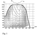
- Figure 1 discloses an engine power efficiency diagram, with engine torque in Newton meter (Nm) presented on the y-axis and engine rotational speed (rpm) presented on the x-axis.
- the thick curve A represents highest possible torque this engine can perform for different engine rpm:s.
- the thinner curves within the x, y-axis and the A-curve represents different efficiency levels for this example of engine.
- the most efficient working area for this engine is designated with a B, thus it is best for the fuel economy if this engine is performing as often as possible somewhere between 1200 to 1500 rpm and between 1800 and up to 2400 Nm.
- the engine rpm is typically needed to be increased to above 1850 rpm or during some circumstances up to even more than 1900 rpm in order to be able to perform some upshifts during certain circumstances.
- the engine power efficiency is relatively low above approximately 1650 rpm.
- Maximum engine rotational speed is according to the example of figure 1 approximately 2000 rpm.
- Said control unit can be programmed to estimate an upshift engine rotational speed, which has to be reached in order to manage to; ramp down engine torque, disengage the presently engaged gear, synchronize engine speed to the new selected gear, engage the new gear and finally ramp up engine torque to meet torque demand from for example driver or a cruise control. Further, the control unit evaluates if there is enough torque available when the new gear will be engaged at a certain engine rotational speed in order to meet the vehicle travel resistance.
- control unit is programmed to estimate if the engine will be able to reach the upshift rotational speed or not under at least present prevailing condition, i. e. calculations are performed with at least above mentioned parameters; current vehicle travel resistance, engine rotational speed, engine rotational speed increase, current engaged gear and torque demand as input information. If the engine is estimated to not reach the upshift rotational speed then an upshift will not be initiated since the engine would be stuck at a relatively high inefficient rpm just below said upshift rotational speed. According to the invention the control unit is further programmed to not increase the engine speed when the result of the above estimation is that the engine speed will not be able to reach the upshift rotational speed.
- control unit is during such a condition programmed to register that the vehicle acceleration has ceased and if there is no other possible gear to upshift to, then the control unit will automatically decrease engine rotational speed down to a more efficient engine rotational speed, for example according to the example shown in figure 1 down to 1500 rpm.
- control unit can be programmed to take a future vehicle condition into account when estimating if the engine will be able to reach the upshift rotational speed or not.
- this could be done by providing the control unit with information from an electronic map and a GPS (Global Positioning System) or the like.
- the electronic map would need to have information about the topography of the landscape in order to foresee for example uphill slopes and its gradients.
- An alterative known solution would be to use a learning system that memorizes the topography first time passing a position and then use this information for above mentioned estimation second time traveling the same position.
- control unit is programmed to return to normal engine control as soon as the vehicle travel resistance is estimated by the control unit to be below a first predetermined level, which first predetermined level is dependent of prevailing vehicle condition and coming upshift rotational speed.
- first predetermined level could be used in order to activate said automatic controlling of the engine torque.
- second predetermined level which differs from said first, and which second predetermined level is used for activation of said automatic controlling of the engine torque.
- Said first and second predetermined levels can of coarse be dynamic, thus being adapted to current and future vehicle conditions.
- said automatic controlling of the engine torque can be inactivated when engine output torque needed for holding a predetermined engine rotational speed during prevailing vehicle travel resistance is below a predetermined engine output torque, for example under 65% of maximum engine output torque.
- a predetermined engine output torque for example under 65% of maximum engine output torque.
- the same or other predetermined engine out torque value can be used the opposite way, that is, in order to activate said automatic controlling of the engine torque.
- control unit could be programmed to be active only when a cruise control in the vehicle is activated.
- control unit could be programmed to allow engine speed increase only if the driver manually demands it through for example an accelerator pedal.
- control unit could be programmed to activate said engine rotational speed limiting function only when the vehicle is driven in a special mode, for example an economy mode.
- control unit could be programmed to override said engine rotational speed limiting function when the driver is using, for example, a kick down function (known prior art) by depressing an accelerator pedal.
- This function to override said engine rotational speed limiting function could also be used in the embodiment above where no cruise control is used.
- Figure 5 shows an apparatus 500 according to one embodiment of the invention, comprising a nonvolatile memory 520, a processor 510 and a read and write memory 560.
- the memory 520 has a first memory part 530, in which a computer program for controlling the apparatus 500 is stored.
- the computer program in the memory part 530 for controlling the apparatus 500 can be an operating system.
- the apparatus 500 can be enclosed in, for example, said control unit.
- the data-processing unit 510 can comprise, for example, a microcomputer.
- the memory 520 also has a second memory part 540, in which a program for said automatic controlling of the engine torque according to the invention is stored.
- the program for automatic controlling of the engine torque is stored in a separate nonvolatile data storage medium 550, such as, for example, a CD or an exchangeable semiconductor memory.
- the program can be stored in an executable form or in a compressed state.
- the data-processing unit 510 runs a specific function, it should be clear that the data-processing unit 510 is running a specific part of the program stored in the memory 540 or a specific part of the program stored in the nonvolatile recording medium 550.
- the data-processing unit 510 is tailored for communication with the memory 550 through a data bus 514.
- the data-processing unit 510 is also tailored for communication with the memory 520 through a data bus 512.
- the data-processing unit 510 is tailored for communication with the memory 560 through a data bus 511.
- the data-processing unit 510 is also tailored for communication with a data port 590 by the use of a data bus 515.
- the method according to the present invention can be executed by the data-processing unit 510, by the data-processing unit 510 running the program stored in the memory 540 or the program stored in the nonvolatile recording medium 550.
Description
- The present invention relates to a method for a more efficient use of a combustion engine in a vehicle, by, during certain vehicle conditions, automatically controlling engine rotational speed in a predetermined way.
- The present invention also relates to a computer program and computer program product both to be used with a computer for executing said method.
- In vehicles equipped with an automatic transmission a situation can sometimes occur in uphill drive where a transmission control unit estimates that an upshift to a new gear will not be possible due to that the engine of the vehicle will not be able to accelerate the vehicle to a sufficiently high vehicle speed so that the engine will manage to drive the vehicle with said new gear engaged. An alternative to the estimation, that the engine of the vehicle will not be able to accelerate the vehicle to a sufficiently high vehicle speed, is to simply register that the engine rotational speed increase has stopped before reaching the right engine rotational speed for upshift. This usually leads to the engine being stuck or "hanging" at relatively high engine rotational speeds without the transmission being able to perform an upshift. A typical example for a heavy duty truck could be that the engine must increase its speed to above 1850 rpm to be able to after an upshift land on a rotational speed with the new gear engaged that gives the engine the possibility to produce enough torque to at least be able to maintain current vehicle speed. In order to gain a better margin it could be necessary to increase the engine rotational speed to even higher rotational speeds, such as 1900 to 1950 rpm, before a gear upshift to the new gear is initiated. At these relatively high engine rotational speeds the efficiency of the engine is relatively low, and having the engine stuck at these relatively high engine rotational speeds contributes to an increased fuel consumption.
-
JP08-295154 -
US6616575 discloses a method to control a driveline where an upshift is performed instead of remaining at a less efficient engine speed, when the engine speed remains at a less efficient rotational speed during a predetermined time. - The object of the present invention is to control the engine rotational speed in a better way in relation to a planned upshift.
- The method according to the invention is a method for a more efficient use of a combustion engine in a vehicle during driving of said vehicle, said vehicle further comprising an automatic step geared transmission for automatic gear ratio adaptation of the gear ratio between the engine rotational speed and rotational speed of driving wheels of the vehicle. Said method comprises the steps of:
- sensing current engine rotational speed and engine rotational speed increase,
- estimating necessary minimum upshift engine rotational speed which has to be reached for a coming gear upshift;
- registering that the engine rotational speed stops increasing without reaching said minimum upshift engine rotational speed at a relatively high but inefficient engine rotational speed just below the said minimum upshift rotational speed or registering that said engine rotational speed stops increasing relatively close to a maximum engine rotational speed where engine efficiency is relatively low and that there is no other possible gear to upshift to; and where said method is further characterized in the step of:
- automatically controlling engine output torque in order to decrease the engine rotational speed to a first predetermined engine speed where engine efficiency is relatively high.
- The advantage with the method according to the invention is that fuel will be saved since unnecessary driving at inefficient engine rotational speeds will be decreased.
- According to one embodiment of the method according to the invention said step of registering that the engine rotational speed stops increasing without reaching said minimum upshift engine rotational speed is performed in advance before reaching said relatively high engine rotational speed where efficiency is relatively low. The advantage with this embodiment is that the driver will not experience any sudden power loss and vehicle speed decrease.
- According to a further embodiment of the method according to the invention, said registering step performed in advance is done through an estimation based on present prevailing vehicle conditions. In a further embodiment of the method according to the invention, said estimation is based on present prevailing vehicle conditions and vehicle conditions estimated likely to occur in near future of the vehicle. The advantage with this embodiment is that the activation and use of said automatic controlling of the engine torque can be further optimized and even more fuel can be saved.
- According to one embodiment of the method according to the invention said automatic controlling of the engine torque can only be active when a cruise control arranged in the vehicle is active. This embodiment allows the driver to have more of a full manual control when driving with the cruise control inactivated.
- According to a further embodiment of the method according to the invention, said automatic controlling of the engine torque can only be active when a first vehicle driving mode is activated, which first driving mode differs from a second driving mode of said vehicle. This first driving mode can for example be an economy mode that can be manually selected and engaged by the driver.
- According to a further embodiment of the method according to the invention, said automatic controlling of the engine torque is inactivated when a driver of the vehicle demands full power to the driving wheels. This gives the driver the possibility to override said automatic controlling in an easy and intuitive way. Thus, for example depressing an accelerator pedal to the floor will give a down shift and vehicle acceleration.
- According to a further embodiment of the method according to the invention, said automatic controlling of the engine torque is inactivated when a predetermined vehicle condition is registered. This predetermined vehicle condition can for example be a decrease of vehicle travel resistance to under a predetermined level. Thus, when the incline of an uphill slope decreases so much that the vehicle travel resistance is below said predetermined value, which decides if said upshift will be possible to perform or not, then the control unit will allow engine rotational speed increase to the upshift engine rotational speed. In a further embodiment said automatic controlling of the engine torque is activated when said vehicle travel resistance has increased to above a second predetermined level. Said first and second level can have the same value or differ from each other.
- According to a further embodiment of the method according to the invention, said automatic controlling of the engine torque is independent of if a driver of the vehicle demands maximum engine output torque or not. Thus, a full automation will minimize the time the engine spends in the inefficient rotational speed area.
- Further advantageous embodiments of the invention emerge from the dependent patent claims following
patent claim 1. - The present invention will be described in greater detail below with reference to the accompanying drawing which, for the purpose of exemplification, shows further preferred embodiments of the invention and also the technical background, and in which:
-
Figure 1 discloses an example of an engine power efficiency diagram that can be used for illustrating the inventive function. -
Figure 2 shows the invention applied on a computer arrangement. - In one embodiment the vehicle is equipped with an internal combustion engine, an automatic step geared transmission and driven wheels, to which drive power from the engine can be transmitted via different gears in the transmission. The different gears are selected and engaged by a transmission control unit. Each selectable gear has a predetermined gear ratio.
- Gear selections and shift decisions are made by said control unit based on certain measured and/or calculated parameters such as vehicle speed, engine speed, rate of change of vehicle speed, rate of change of engine speed, throttle control position, rate of change of throttle control position, actuation of a vehicle braking system, currently engaged gear ratio and the like are known from prior art.
- In a first preferred embodiment of the invention said control unit is programmed to estimate if a selected, not yet performed upshift is feasible. This estimation is based on a calculation with input parameters such as at least current vehicle travel resistance, engine rotational speed, engine rotational speed increase, current engaged gear and torque demand (driver demand or for example cruise control demand). These parameters could also be supplemented by parameters such as estimated vehicle travel resistance of the nearest future in order to be able to achieve a better estimation.
-
Figure 1 discloses an engine power efficiency diagram, with engine torque in Newton meter (Nm) presented on the y-axis and engine rotational speed (rpm) presented on the x-axis. The thick curve A represents highest possible torque this engine can perform for different engine rpm:s. The thinner curves within the x, y-axis and the A-curve represents different efficiency levels for this example of engine. The most efficient working area for this engine is designated with a B, thus it is best for the fuel economy if this engine is performing as often as possible somewhere between 1200 to 1500 rpm and between 1800 and up to 2400 Nm. Above is mentioned that the engine rpm is typically needed to be increased to above 1850 rpm or during some circumstances up to even more than 1900 rpm in order to be able to perform some upshifts during certain circumstances. As can be seen in the diagram the engine power efficiency is relatively low above approximately 1650 rpm. Maximum engine rotational speed is according to the example offigure 1 approximately 2000 rpm. - Said control unit can be programmed to estimate an upshift engine rotational speed, which has to be reached in order to manage to; ramp down engine torque, disengage the presently engaged gear, synchronize engine speed to the new selected gear, engage the new gear and finally ramp up engine torque to meet torque demand from for example driver or a cruise control. Further, the control unit evaluates if there is enough torque available when the new gear will be engaged at a certain engine rotational speed in order to meet the vehicle travel resistance.
- According to the invention said control unit is programmed to estimate if the engine will be able to reach the upshift rotational speed or not under at least present prevailing condition, i. e. calculations are performed with at least above mentioned parameters; current vehicle travel resistance, engine rotational speed, engine rotational speed increase, current engaged gear and torque demand as input information. If the engine is estimated to not reach the upshift rotational speed then an upshift will not be initiated since the engine would be stuck at a relatively high inefficient rpm just below said upshift rotational speed. According to the invention the control unit is further programmed to not increase the engine speed when the result of the above estimation is that the engine speed will not be able to reach the upshift rotational speed.
- There could be a situation in an uphill slope where the control unit has estimated that an upshift is possible, thus the engine rotational speed is allowed to increase towards the upshift rotational speed. But before the upshift rotational speed has been reached it can happen that the vehicle travel resistance increases to a level where the engine torque will not be enough to keep on accelerating the vehicle and, thus ,the engine rotational speed increase ceases at a relatively high but inefficient engine rotational speed without having reached the upshift rotational speed. According to another embodiment of the invention the control unit is during such a condition programmed to register that the vehicle acceleration has ceased and if there is no other possible gear to upshift to, then the control unit will automatically decrease engine rotational speed down to a more efficient engine rotational speed, for example according to the example shown in
figure 1 down to 1500 rpm. - In an alternative embodiment of the invention the control unit can be programmed to take a future vehicle condition into account when estimating if the engine will be able to reach the upshift rotational speed or not. According to known art this could be done by providing the control unit with information from an electronic map and a GPS (Global Positioning System) or the like. The electronic map would need to have information about the topography of the landscape in order to foresee for example uphill slopes and its gradients. An alterative known solution would be to use a learning system that memorizes the topography first time passing a position and then use this information for above mentioned estimation second time traveling the same position.
- In a further developed embodiment of the invention the control unit is programmed to return to normal engine control as soon as the vehicle travel resistance is estimated by the control unit to be below a first predetermined level, which first predetermined level is dependent of prevailing vehicle condition and coming upshift rotational speed. The same first predetermined level could be used in order to activate said automatic controlling of the engine torque. It is also possible to have a second predetermined level, which differs from said first, and which second predetermined level is used for activation of said automatic controlling of the engine torque. Said first and second predetermined levels can of coarse be dynamic, thus being adapted to current and future vehicle conditions.
- In a further embodiment of the invention said automatic controlling of the engine torque can be inactivated when engine output torque needed for holding a predetermined engine rotational speed during prevailing vehicle travel resistance is below a predetermined engine output torque, for example under 65% of maximum engine output torque. The same or other predetermined engine out torque value can be used the opposite way, that is, in order to activate said automatic controlling of the engine torque.
- The above mentioned embodiments of the invention could be programmed to be active only when a cruise control in the vehicle is activated. Thus, if the control unit during cruise control limits the engine speed to a more efficient rpm level then the control unit could be programmed to allow engine speed increase only if the driver manually demands it through for example an accelerator pedal.
- In a further embodiment the control unit could be programmed to activate said engine rotational speed limiting function only when the vehicle is driven in a special mode, for example an economy mode.
- In a further embodiment the control unit could be programmed to override said engine rotational speed limiting function when the driver is using, for example, a kick down function (known prior art) by depressing an accelerator pedal. This function to override said engine rotational speed limiting function could also be used in the embodiment above where no cruise control is used.
- Figure 5 shows an
apparatus 500 according to one embodiment of the invention, comprising anonvolatile memory 520, aprocessor 510 and a read and writememory 560. Thememory 520 has afirst memory part 530, in which a computer program for controlling theapparatus 500 is stored. The computer program in thememory part 530 for controlling theapparatus 500 can be an operating system. - The
apparatus 500 can be enclosed in, for example, said control unit. The data-processing unit 510 can comprise, for example, a microcomputer. - The
memory 520 also has asecond memory part 540, in which a program for said automatic controlling of the engine torque according to the invention is stored. In an alternative embodiment, the program for automatic controlling of the engine torque is stored in a separate nonvolatiledata storage medium 550, such as, for example, a CD or an exchangeable semiconductor memory. The program can be stored in an executable form or in a compressed state. - When it is stated below that the data-
processing unit 510 runs a specific function, it should be clear that the data-processing unit 510 is running a specific part of the program stored in thememory 540 or a specific part of the program stored in thenonvolatile recording medium 550. - The data-
processing unit 510 is tailored for communication with thememory 550 through adata bus 514. The data-processing unit 510 is also tailored for communication with thememory 520 through adata bus 512. In addition, the data-processing unit 510 is tailored for communication with thememory 560 through adata bus 511. The data-processing unit 510 is also tailored for communication with adata port 590 by the use of adata bus 515. - The method according to the present invention can be executed by the data-
processing unit 510, by the data-processing unit 510 running the program stored in thememory 540 or the program stored in thenonvolatile recording medium 550. - The invention should not be deemed to be limited to the embodiments described above, but rather a number of further variants and modifications are conceivable within the scope of the following patent claims.
Claims (14)
- A method for a more efficient use of a combustion engine in a vehicle during driving of said vehicle, said vehicle further comprising an automatic step geared transmission for automatic gear ratio adaptation of the gear ratio between the engine rotational speed and rotational speed of driving wheels of the vehicle, said method comprising the steps of:- sensing current engine rotational speed and engine rotational speed increase,- estimating necessary minimum upshift engine rotational speed which has to be reached for a coming gear upshift;- registering that the engine rotational speed stops increasing without reaching said minimum upshift engine rotational speed at a relatively high but inefficient engine rotational speed just below the said minimum upshift rotational speed or registering that said engine rotational speed stops increasing relatively close to a maximum engine rotational speed where engine efficiency is relatively low and that there is no other possible gear to upshift to;
and where said method is further characterized in the step of:- automatically controlling engine output torque in order to decrease the engine rotational speed to a first predetermined engine speed, without initiating a gear upshift, where engine efficiency is relatively high. - A method as in claim 1, characterized in that said step of registering that the engine rotational speed stops increasing without reaching said minimum upshift engine rotational speed is performed in advance before reaching said relatively high engine rotational speed where efficiency is relatively low.
- A method as in the preceding claim, characterized in that said registering step performed in advance is done through an estimation based on present prevailing vehicle conditions.
- A method as in the preceding claim, characterized in that said estimation is based on present prevailing vehicle conditions and vehicle conditions estimated likely to occur in near future of the vehicle.
- A method as in one of the preceding claims, characterized in that said automatic controlling of the engine torque can only be active when a cruise control arranged in the vehicle is active.
- A method as in one of the preceding claims, characterized in that said automatic controlling of the engine torque can only be active when a first vehicle driving mode is activated, which first driving mode differs from a second driving mode of said vehicle.
- A method as in one of the preceding claims, characterized in that said automatic controlling of the engine torque is inactivated when a driver of the vehicle demands full power to the driving wheels.
- A method as in one of the preceding claims, characterized in that said automatic controlling of the engine torque is inactivated when a predetermined vehicle condition is registered.
- A method as in the preceding claim, characterized in that said predetermined vehicle condition is a decrease of vehicle travel resistance to under a first predetermined level.
- A method as in the preceding claim, characterized in that said automatic controlling of the engine torque is activated when said vehicle travel resistance has increased to above a second predetermined level.
- A method as in claim 1, characterized in that said automatic controlling of the engine torque is independent of if a driver of the vehicle demands maximum engine output torque or not.
- A computer program comprising a program code for executing the method as claimed in claim 1, when said computer program is executed on a computer for controlling a combustion engine in a vehicle, the vehicle having the technical features as defined in claim 1.
- A computer program product comprising a program code, stored on a computerreadable medium, for executing the method as claimed in claim 1, when said computer program is executed on the computer for controlling a combustion engine in a vehicle, the vehicle having the technical features as defined in claim 1.
- A computer program product directly loadable into an internal memory in a computer, which computer program product comprises a computer program for executing the method as claimed in claim 1, when said computer program on the computer program product is executed on the computer for controlling a combustion engine in a vehicle, the vehicle having the technical features as defined in claim 1.
Applications Claiming Priority (1)
| Application Number | Priority Date | Filing Date | Title |
|---|---|---|---|
| PCT/SE2007/000946 WO2009054757A1 (en) | 2007-10-26 | 2007-10-26 | A method for a more efficient use of a combustion engine in a vehicle |
Publications (3)
| Publication Number | Publication Date |
|---|---|
| EP2212148A1 EP2212148A1 (en) | 2010-08-04 |
| EP2212148A4 EP2212148A4 (en) | 2014-01-29 |
| EP2212148B1 true EP2212148B1 (en) | 2021-04-28 |
Family
ID=40579747
Family Applications (1)
| Application Number | Title | Priority Date | Filing Date |
|---|---|---|---|
| EP07835146.7A Active EP2212148B1 (en) | 2007-10-26 | 2007-10-26 | A method for a more efficient use of a combustion engine in a vehicle provided with an automatic step gear transmission |
Country Status (6)
| Country | Link |
|---|---|
| US (1) | US10330029B2 (en) |
| EP (1) | EP2212148B1 (en) |
| JP (1) | JP5346031B2 (en) |
| CN (1) | CN101842259B (en) |
| BR (1) | BRPI0722257B1 (en) |
| WO (1) | WO2009054757A1 (en) |
Families Citing this family (7)
| Publication number | Priority date | Publication date | Assignee | Title |
|---|---|---|---|---|
| JP5077445B2 (en) * | 2009-02-13 | 2012-11-21 | トヨタ自動車株式会社 | Driving force control device |
| SE537867C2 (en) * | 2012-12-17 | 2015-11-03 | Scania Cv Ab | Procedure and system for controlling driver behavior when driving a motor vehicle |
| EP2921676B1 (en) | 2014-03-21 | 2017-08-02 | Perkins Engines Company Limited | Process and system for controlling engine speed |
| GB2535700B (en) | 2015-02-20 | 2017-09-06 | Ford Global Tech Llc | A method for reducing the amount of fuel used by an engine of a motor vehicle |
| JP7000214B2 (en) * | 2018-03-20 | 2022-01-19 | 本田技研工業株式会社 | Vehicle control device |
| US10640062B2 (en) * | 2018-05-09 | 2020-05-05 | Karma Automotive Llc | Intelligent power management for a vehicle |
| US10730505B2 (en) * | 2018-05-09 | 2020-08-04 | Karma Automotive Llc | Hybrid electric vehicle using intelligent vehicle controller |
Family Cites Families (44)
| Publication number | Priority date | Publication date | Assignee | Title |
|---|---|---|---|---|
| US4905544A (en) * | 1975-09-25 | 1990-03-06 | Ganoung David P | Powertrain control apparatus for improving fuel economy |
| US4102222A (en) * | 1977-01-03 | 1978-07-25 | Borg-Warner Corporation | Transmission control system |
| US4630508A (en) * | 1983-03-28 | 1986-12-23 | Wabco Westinghouse Fahrzeugbremsen Gmbh | Method and apparatus to determine constant speed torque on an engine |
| JPH0712810B2 (en) * | 1985-05-28 | 1995-02-15 | トヨタ自動車株式会社 | Speed ratio control device for continuously variable transmission for vehicles |
| JP2813670B2 (en) * | 1989-11-30 | 1998-10-22 | 富士重工業株式会社 | Control device for continuously variable transmission with lock-up torque converter |
| JP3183968B2 (en) * | 1992-10-20 | 2001-07-09 | 本田技研工業株式会社 | Power transmission device for vehicles |
| IT1267654B1 (en) * | 1994-12-29 | 1997-02-07 | Iveco Fiat | METHOD OF CONTROL OF A MOTOR-DRIVER GROUP OF A VEHICLE. |
| US5544056A (en) * | 1995-01-23 | 1996-08-06 | Seireg; Ali A. | Computerized control of automobile speed |
| JP3067584B2 (en) | 1995-04-28 | 2000-07-17 | 三菱自動車工業株式会社 | Auto cruise control method |
| FR2737761B1 (en) * | 1995-08-10 | 1997-09-19 | Renault | PROCESS FOR REMOVING THE PUMPING PHENOMENON OF A MOTOR VEHICLE AND MOTOR VEHICLE IMPLEMENTING THIS PROCESS |
| US5685801A (en) * | 1996-06-14 | 1997-11-11 | Chrysler Corporation | Cruise control overspeed reduction with automatic transmission |
| US6944532B2 (en) * | 1998-06-18 | 2005-09-13 | Cummins, Inc. | System for controlling an internal combustion engine in a fuel efficient manner |
| US6076036A (en) * | 1998-10-05 | 2000-06-13 | Price; Christopher C. | Vehicle cruise control |
| DE19908250A1 (en) * | 1999-02-25 | 2000-08-31 | Zahnradfabrik Friedrichshafen | Transmission ratio regulation for continuous automatic gearbox involves correction element taking account of internal and external system parameters in physical mathematical model |
| DE19911538C1 (en) * | 1999-03-16 | 2000-11-23 | Daimler Chrysler Ag | Transmission ratio adjustment device for continuously variable transmission used for vehicle velocity regulation, has adjustment value provided by velocity regulator corrected by summation with stored value |
| US6503170B1 (en) * | 1999-08-20 | 2003-01-07 | Toyota Jidosha Kabushiki Kaisha | Control device for an automatic transmission |
| US6616575B1 (en) * | 1999-10-29 | 2003-09-09 | Caterpillar Inc | Method and apparatus for operating a transmission coupled to an engine for enhanced fuel efficiency characteristics |
| US6278931B1 (en) * | 2000-04-04 | 2001-08-21 | Delphi Technologies, Inc. | Motor vehicle cruise control with selectively updated integral gain |
| FR2813050B1 (en) * | 2000-08-17 | 2002-11-22 | Renault | METHOD AND SYSTEM FOR REGULATING THE SPEED OF A MOTOR VEHICLE |
| US6718251B2 (en) * | 2002-01-29 | 2004-04-06 | Cummins, Inc. | System for controlling exhaust emissions produced by an internal combustion engine |
| JP3952884B2 (en) * | 2002-07-19 | 2007-08-01 | トヨタ自動車株式会社 | Automotive control device |
| JP2004108300A (en) * | 2002-09-19 | 2004-04-08 | Jatco Ltd | Engine torque predicting device and engine torque predicting method |
| JP4134654B2 (en) * | 2002-09-25 | 2008-08-20 | 日産自動車株式会社 | Idle speed control device for internal combustion engine |
| SE525032C2 (en) * | 2003-05-07 | 2004-11-16 | Volvo Lastvagnar Ab | Procedure and arrangement for automated control of a vehicle drive system |
| US7497201B2 (en) * | 2003-11-18 | 2009-03-03 | Mack Trucks, Inc. | Control system and method for improving fuel economy |
| DE102004002813A1 (en) | 2004-01-20 | 2005-08-11 | Adam Opel Ag | Method for selecting gear in automatic transmission unit, using comparison of actual speed and possible acceleration |
| EP1559893B1 (en) * | 2004-01-30 | 2006-09-13 | Nissan Motor Co., Ltd. | Control apparatus and process for internal combustion engine |
| JP4461950B2 (en) * | 2004-07-09 | 2010-05-12 | ミヤマ株式会社 | Vehicle with automatic transmission |
| US7263429B2 (en) * | 2005-08-11 | 2007-08-28 | Gm Global Technology Operations, Inc. | Cruise idle speed control to enhance low speed and light throttle drivability |
| JP4240029B2 (en) * | 2005-10-14 | 2009-03-18 | トヨタ自動車株式会社 | Vehicle and control method thereof |
| JP2007112258A (en) * | 2005-10-19 | 2007-05-10 | Nissan Motor Co Ltd | Engine start controller of hybrid drive unit |
| JP4188359B2 (en) * | 2005-10-31 | 2008-11-26 | 本田技研工業株式会社 | Shift control device for automatic transmission |
| JP4188360B2 (en) * | 2005-10-31 | 2008-11-26 | 本田技研工業株式会社 | Shift control device for automatic transmission |
| BRPI0520732B1 (en) * | 2005-12-09 | 2018-05-29 | Volvo Lastvagnar Ab | A METHOD FOR GEAR SELECTION DURING A VEHICLE TRACTION IN A SEVERA ASCENT TRACTION CONDITION |
| KR100793869B1 (en) * | 2005-12-17 | 2008-01-15 | 현대자동차주식회사 | Adative cruise control system for vehicle |
| US7684919B2 (en) * | 2006-05-23 | 2010-03-23 | Zf Friedrichshafen Ag | Multiple speed transmission having fuel economy mode |
| US7556585B2 (en) * | 2006-06-19 | 2009-07-07 | Caterpillar Inc. | Machine drive line overspeed protection method |
| US7717823B2 (en) * | 2006-11-27 | 2010-05-18 | Zf Friedrichshafen Ag | Method and apparatus for changing shift scheduling modes of automated mechanical transmission |
| JP4113919B2 (en) * | 2006-12-12 | 2008-07-09 | トヨタ自動車株式会社 | Powertrain control device, control method, program for realizing the method, and recording medium recording the program |
| US7987934B2 (en) * | 2007-03-29 | 2011-08-02 | GM Global Technology Operations LLC | Method for controlling engine speed in a hybrid electric vehicle |
| US8370032B2 (en) * | 2007-07-12 | 2013-02-05 | Toyota Motor Engineering & Manufacturing North America, Inc. | Systems and methods for shift control for vehicular transmission |
| US7993243B2 (en) * | 2008-03-14 | 2011-08-09 | Ford Global Technologies, Llc | Detecting operation of a vehicle on an ascending grade |
| US8145398B2 (en) * | 2008-11-12 | 2012-03-27 | Caterpillar Inc. | Method for controlling gear ratio changes in an automatic transmission |
| KR20150104232A (en) * | 2010-10-04 | 2015-09-14 | 알리손 트랜스미션, 인크. | System for selecting a transmission economy-based shift schedule |
-
2007
- 2007-10-26 WO PCT/SE2007/000946 patent/WO2009054757A1/en active Application Filing
- 2007-10-26 US US12/739,155 patent/US10330029B2/en active Active
- 2007-10-26 BR BRPI0722257-2A patent/BRPI0722257B1/en active IP Right Grant
- 2007-10-26 EP EP07835146.7A patent/EP2212148B1/en active Active
- 2007-10-26 CN CN2007801012466A patent/CN101842259B/en active Active
- 2007-10-26 JP JP2010530952A patent/JP5346031B2/en active Active
Non-Patent Citations (1)
| Title |
|---|
| None * |
Also Published As
| Publication number | Publication date |
|---|---|
| JP5346031B2 (en) | 2013-11-20 |
| US20100262343A1 (en) | 2010-10-14 |
| CN101842259B (en) | 2013-05-15 |
| BRPI0722257A2 (en) | 2014-04-08 |
| US10330029B2 (en) | 2019-06-25 |
| BRPI0722257B1 (en) | 2019-07-30 |
| JP2011501041A (en) | 2011-01-06 |
| WO2009054757A1 (en) | 2009-04-30 |
| EP2212148A4 (en) | 2014-01-29 |
| EP2212148A1 (en) | 2010-08-04 |
| CN101842259A (en) | 2010-09-22 |
Similar Documents
| Publication | Publication Date | Title |
|---|---|---|
| JP5390714B2 (en) | Method and system for controlling a cruise control device of a vehicle | |
| US8788174B2 (en) | Method for increasing active duration time of an automatic freewheeling function in a vehicle | |
| US9096229B2 (en) | Method and system for controlling a vehicle cruise control | |
| EP2379391B1 (en) | Method and device for controlling a vehicle cruise control | |
| JP4897663B2 (en) | Method and system for automatic freewheeling of automobiles | |
| EP2427358B1 (en) | Method and device for controlling an automatic freewheeling function in a vehicle | |
| EP2212148B1 (en) | A method for a more efficient use of a combustion engine in a vehicle provided with an automatic step gear transmission | |
| US8392079B2 (en) | Vehicle, control method and control apparatus for vehicle | |
| WO2013104617A1 (en) | A method for reducing vehicle fuel consumption during coasting | |
| US10054220B2 (en) | System and method for controlling shift for vehicle | |
| RU2457128C2 (en) | Method of more effective use of internal-combustion engine | |
| JP2006266151A (en) | Engine control device |
Legal Events
| Date | Code | Title | Description |
|---|---|---|---|
| PUAI | Public reference made under article 153(3) epc to a published international application that has entered the european phase |
Free format text: ORIGINAL CODE: 0009012 |
|
| 17P | Request for examination filed |
Effective date: 20100526 |
|
| AK | Designated contracting states |
Kind code of ref document: A1 Designated state(s): AT BE BG CH CY CZ DE DK EE ES FI FR GB GR HU IE IS IT LI LT LU LV MC MT NL PL PT RO SE SI SK TR |
|
| AX | Request for extension of the european patent |
Extension state: AL BA HR MK RS |
|
| DAX | Request for extension of the european patent (deleted) | ||
| A4 | Supplementary search report drawn up and despatched |
Effective date: 20140108 |
|
| RIC1 | Information provided on ipc code assigned before grant |
Ipc: F02D 29/02 20060101AFI20131220BHEP Ipc: B60W 10/06 20060101ALI20131220BHEP Ipc: F02D 31/00 20060101ALI20131220BHEP Ipc: B60W 50/08 20120101ALI20131220BHEP Ipc: B60W 30/188 20120101ALI20131220BHEP Ipc: F16H 61/02 20060101ALI20131220BHEP |
|
| STAA | Information on the status of an ep patent application or granted ep patent |
Free format text: STATUS: EXAMINATION IS IN PROGRESS |
|
| 17Q | First examination report despatched |
Effective date: 20180307 |
|
| REG | Reference to a national code |
Ref country code: DE Ref legal event code: R079 Ref document number: 602007061093 Country of ref document: DE Free format text: PREVIOUS MAIN CLASS: B60K0031040000 Ipc: F02D0031000000 |
|
| GRAP | Despatch of communication of intention to grant a patent |
Free format text: ORIGINAL CODE: EPIDOSNIGR1 |
|
| STAA | Information on the status of an ep patent application or granted ep patent |
Free format text: STATUS: GRANT OF PATENT IS INTENDED |
|
| RIC1 | Information provided on ipc code assigned before grant |
Ipc: F02D 41/02 20060101ALN20201106BHEP Ipc: F16H 61/16 20060101ALN20201106BHEP Ipc: F16H 59/36 20060101ALN20201106BHEP Ipc: F02D 31/00 20060101AFI20201106BHEP Ipc: B60W 50/08 20200101ALI20201106BHEP Ipc: B60W 30/188 20120101ALI20201106BHEP Ipc: F02D 29/02 20060101ALI20201106BHEP Ipc: B60W 10/06 20060101ALI20201106BHEP |
|
| RIC1 | Information provided on ipc code assigned before grant |
Ipc: F02D 41/02 20060101ALN20201123BHEP Ipc: B60W 50/08 20200101ALI20201123BHEP Ipc: F16H 61/16 20060101ALN20201123BHEP Ipc: F02D 29/02 20060101ALI20201123BHEP Ipc: F16H 59/36 20060101ALN20201123BHEP Ipc: B60W 10/06 20060101ALI20201123BHEP Ipc: F02D 31/00 20060101AFI20201123BHEP Ipc: B60W 30/188 20120101ALI20201123BHEP |
|
| INTG | Intention to grant announced |
Effective date: 20201211 |
|
| GRAS | Grant fee paid |
Free format text: ORIGINAL CODE: EPIDOSNIGR3 |
|
| GRAA | (expected) grant |
Free format text: ORIGINAL CODE: 0009210 |
|
| STAA | Information on the status of an ep patent application or granted ep patent |
Free format text: STATUS: THE PATENT HAS BEEN GRANTED |
|
| AK | Designated contracting states |
Kind code of ref document: B1 Designated state(s): AT BE BG CH CY CZ DE DK EE ES FI FR GB GR HU IE IS IT LI LT LU LV MC MT NL PL PT RO SE SI SK TR |
|
| REG | Reference to a national code |
Ref country code: GB Ref legal event code: FG4D |
|
| REG | Reference to a national code |
Ref country code: CH Ref legal event code: EP |
|
| REG | Reference to a national code |
Ref country code: AT Ref legal event code: REF Ref document number: 1387318 Country of ref document: AT Kind code of ref document: T Effective date: 20210515 |
|
| REG | Reference to a national code |
Ref country code: DE Ref legal event code: R096 Ref document number: 602007061093 Country of ref document: DE |
|
| REG | Reference to a national code |
Ref country code: IE Ref legal event code: FG4D |
|
| REG | Reference to a national code |
Ref country code: NL Ref legal event code: FP |
|
| REG | Reference to a national code |
Ref country code: SE Ref legal event code: TRGR |
|
| REG | Reference to a national code |
Ref country code: LT Ref legal event code: MG9D |
|
| REG | Reference to a national code |
Ref country code: AT Ref legal event code: MK05 Ref document number: 1387318 Country of ref document: AT Kind code of ref document: T Effective date: 20210428 |
|
| PG25 | Lapsed in a contracting state [announced via postgrant information from national office to epo] |
Ref country code: FI Free format text: LAPSE BECAUSE OF FAILURE TO SUBMIT A TRANSLATION OF THE DESCRIPTION OR TO PAY THE FEE WITHIN THE PRESCRIBED TIME-LIMIT Effective date: 20210428 Ref country code: LT Free format text: LAPSE BECAUSE OF FAILURE TO SUBMIT A TRANSLATION OF THE DESCRIPTION OR TO PAY THE FEE WITHIN THE PRESCRIBED TIME-LIMIT Effective date: 20210428 Ref country code: BG Free format text: LAPSE BECAUSE OF FAILURE TO SUBMIT A TRANSLATION OF THE DESCRIPTION OR TO PAY THE FEE WITHIN THE PRESCRIBED TIME-LIMIT Effective date: 20210728 Ref country code: AT Free format text: LAPSE BECAUSE OF FAILURE TO SUBMIT A TRANSLATION OF THE DESCRIPTION OR TO PAY THE FEE WITHIN THE PRESCRIBED TIME-LIMIT Effective date: 20210428 |
|
| PG25 | Lapsed in a contracting state [announced via postgrant information from national office to epo] |
Ref country code: PT Free format text: LAPSE BECAUSE OF FAILURE TO SUBMIT A TRANSLATION OF THE DESCRIPTION OR TO PAY THE FEE WITHIN THE PRESCRIBED TIME-LIMIT Effective date: 20210830 Ref country code: PL Free format text: LAPSE BECAUSE OF FAILURE TO SUBMIT A TRANSLATION OF THE DESCRIPTION OR TO PAY THE FEE WITHIN THE PRESCRIBED TIME-LIMIT Effective date: 20210428 Ref country code: ES Free format text: LAPSE BECAUSE OF FAILURE TO SUBMIT A TRANSLATION OF THE DESCRIPTION OR TO PAY THE FEE WITHIN THE PRESCRIBED TIME-LIMIT Effective date: 20210428 Ref country code: LV Free format text: LAPSE BECAUSE OF FAILURE TO SUBMIT A TRANSLATION OF THE DESCRIPTION OR TO PAY THE FEE WITHIN THE PRESCRIBED TIME-LIMIT Effective date: 20210428 Ref country code: GR Free format text: LAPSE BECAUSE OF FAILURE TO SUBMIT A TRANSLATION OF THE DESCRIPTION OR TO PAY THE FEE WITHIN THE PRESCRIBED TIME-LIMIT Effective date: 20210729 Ref country code: IS Free format text: LAPSE BECAUSE OF FAILURE TO SUBMIT A TRANSLATION OF THE DESCRIPTION OR TO PAY THE FEE WITHIN THE PRESCRIBED TIME-LIMIT Effective date: 20210828 |
|
| PG25 | Lapsed in a contracting state [announced via postgrant information from national office to epo] |
Ref country code: RO Free format text: LAPSE BECAUSE OF FAILURE TO SUBMIT A TRANSLATION OF THE DESCRIPTION OR TO PAY THE FEE WITHIN THE PRESCRIBED TIME-LIMIT Effective date: 20210428 Ref country code: DK Free format text: LAPSE BECAUSE OF FAILURE TO SUBMIT A TRANSLATION OF THE DESCRIPTION OR TO PAY THE FEE WITHIN THE PRESCRIBED TIME-LIMIT Effective date: 20210428 Ref country code: EE Free format text: LAPSE BECAUSE OF FAILURE TO SUBMIT A TRANSLATION OF THE DESCRIPTION OR TO PAY THE FEE WITHIN THE PRESCRIBED TIME-LIMIT Effective date: 20210428 Ref country code: CZ Free format text: LAPSE BECAUSE OF FAILURE TO SUBMIT A TRANSLATION OF THE DESCRIPTION OR TO PAY THE FEE WITHIN THE PRESCRIBED TIME-LIMIT Effective date: 20210428 Ref country code: SK Free format text: LAPSE BECAUSE OF FAILURE TO SUBMIT A TRANSLATION OF THE DESCRIPTION OR TO PAY THE FEE WITHIN THE PRESCRIBED TIME-LIMIT Effective date: 20210428 |
|
| REG | Reference to a national code |
Ref country code: DE Ref legal event code: R097 Ref document number: 602007061093 Country of ref document: DE |
|
| PLBE | No opposition filed within time limit |
Free format text: ORIGINAL CODE: 0009261 |
|
| STAA | Information on the status of an ep patent application or granted ep patent |
Free format text: STATUS: NO OPPOSITION FILED WITHIN TIME LIMIT |
|
| 26N | No opposition filed |
Effective date: 20220131 |
|
| REG | Reference to a national code |
Ref country code: CH Ref legal event code: PL |
|
| PG25 | Lapsed in a contracting state [announced via postgrant information from national office to epo] |
Ref country code: IS Free format text: LAPSE BECAUSE OF FAILURE TO SUBMIT A TRANSLATION OF THE DESCRIPTION OR TO PAY THE FEE WITHIN THE PRESCRIBED TIME-LIMIT Effective date: 20210828 |
|
| REG | Reference to a national code |
Ref country code: BE Ref legal event code: MM Effective date: 20211031 |
|
| GBPC | Gb: european patent ceased through non-payment of renewal fee |
Effective date: 20211026 |
|
| PG25 | Lapsed in a contracting state [announced via postgrant information from national office to epo] |
Ref country code: MC Free format text: LAPSE BECAUSE OF FAILURE TO SUBMIT A TRANSLATION OF THE DESCRIPTION OR TO PAY THE FEE WITHIN THE PRESCRIBED TIME-LIMIT Effective date: 20210428 |
|
| PG25 | Lapsed in a contracting state [announced via postgrant information from national office to epo] |
Ref country code: LU Free format text: LAPSE BECAUSE OF NON-PAYMENT OF DUE FEES Effective date: 20211026 Ref country code: IT Free format text: LAPSE BECAUSE OF FAILURE TO SUBMIT A TRANSLATION OF THE DESCRIPTION OR TO PAY THE FEE WITHIN THE PRESCRIBED TIME-LIMIT Effective date: 20210428 Ref country code: GB Free format text: LAPSE BECAUSE OF NON-PAYMENT OF DUE FEES Effective date: 20211026 Ref country code: BE Free format text: LAPSE BECAUSE OF NON-PAYMENT OF DUE FEES Effective date: 20211031 |
|
| PG25 | Lapsed in a contracting state [announced via postgrant information from national office to epo] |
Ref country code: LI Free format text: LAPSE BECAUSE OF NON-PAYMENT OF DUE FEES Effective date: 20211031 Ref country code: CH Free format text: LAPSE BECAUSE OF NON-PAYMENT OF DUE FEES Effective date: 20211031 |
|
| PG25 | Lapsed in a contracting state [announced via postgrant information from national office to epo] |
Ref country code: IE Free format text: LAPSE BECAUSE OF NON-PAYMENT OF DUE FEES Effective date: 20211026 |
|
| PG25 | Lapsed in a contracting state [announced via postgrant information from national office to epo] |
Ref country code: HU Free format text: LAPSE BECAUSE OF FAILURE TO SUBMIT A TRANSLATION OF THE DESCRIPTION OR TO PAY THE FEE WITHIN THE PRESCRIBED TIME-LIMIT; INVALID AB INITIO Effective date: 20071026 Ref country code: CY Free format text: LAPSE BECAUSE OF FAILURE TO SUBMIT A TRANSLATION OF THE DESCRIPTION OR TO PAY THE FEE WITHIN THE PRESCRIBED TIME-LIMIT Effective date: 20210428 |
|
| PGFP | Annual fee paid to national office [announced via postgrant information from national office to epo] |
Ref country code: NL Payment date: 20231026 Year of fee payment: 17 |
|
| PGFP | Annual fee paid to national office [announced via postgrant information from national office to epo] |
Ref country code: SE Payment date: 20231023 Year of fee payment: 17 Ref country code: FR Payment date: 20231026 Year of fee payment: 17 Ref country code: DE Payment date: 20231027 Year of fee payment: 17 |