EP4011631A1 - Processing device and recording device - Google Patents
Processing device and recording device Download PDFInfo
- Publication number
- EP4011631A1 EP4011631A1 EP21204309.5A EP21204309A EP4011631A1 EP 4011631 A1 EP4011631 A1 EP 4011631A1 EP 21204309 A EP21204309 A EP 21204309A EP 4011631 A1 EP4011631 A1 EP 4011631A1
- Authority
- EP
- European Patent Office
- Prior art keywords
- housing
- opening
- near field
- field communication
- cover member
- Prior art date
- Legal status (The legal status is an assumption and is not a legal conclusion. Google has not performed a legal analysis and makes no representation as to the accuracy of the status listed.)
- Granted
Links
Images


Classifications
-
- B—PERFORMING OPERATIONS; TRANSPORTING
- B41—PRINTING; LINING MACHINES; TYPEWRITERS; STAMPS
- B41J—TYPEWRITERS; SELECTIVE PRINTING MECHANISMS, i.e. MECHANISMS PRINTING OTHERWISE THAN FROM A FORME; CORRECTION OF TYPOGRAPHICAL ERRORS
- B41J29/00—Details of, or accessories for, typewriters or selective printing mechanisms not otherwise provided for
- B41J29/02—Framework
-
- B—PERFORMING OPERATIONS; TRANSPORTING
- B41—PRINTING; LINING MACHINES; TYPEWRITERS; STAMPS
- B41J—TYPEWRITERS; SELECTIVE PRINTING MECHANISMS, i.e. MECHANISMS PRINTING OTHERWISE THAN FROM A FORME; CORRECTION OF TYPOGRAPHICAL ERRORS
- B41J2/00—Typewriters or selective printing mechanisms characterised by the printing or marking process for which they are designed
- B41J2/005—Typewriters or selective printing mechanisms characterised by the printing or marking process for which they are designed characterised by bringing liquid or particles selectively into contact with a printing material
- B41J2/01—Ink jet
-
- B—PERFORMING OPERATIONS; TRANSPORTING
- B41—PRINTING; LINING MACHINES; TYPEWRITERS; STAMPS
- B41J—TYPEWRITERS; SELECTIVE PRINTING MECHANISMS, i.e. MECHANISMS PRINTING OTHERWISE THAN FROM A FORME; CORRECTION OF TYPOGRAPHICAL ERRORS
- B41J29/00—Details of, or accessories for, typewriters or selective printing mechanisms not otherwise provided for
- B41J29/12—Guards, shields or dust excluders
- B41J29/13—Cases or covers
-
- B—PERFORMING OPERATIONS; TRANSPORTING
- B41—PRINTING; LINING MACHINES; TYPEWRITERS; STAMPS
- B41J—TYPEWRITERS; SELECTIVE PRINTING MECHANISMS, i.e. MECHANISMS PRINTING OTHERWISE THAN FROM A FORME; CORRECTION OF TYPOGRAPHICAL ERRORS
- B41J29/00—Details of, or accessories for, typewriters or selective printing mechanisms not otherwise provided for
- B41J29/38—Drives, motors, controls or automatic cut-off devices for the entire printing mechanism
- B41J29/393—Devices for controlling or analysing the entire machine ; Controlling or analysing mechanical parameters involving printing of test patterns
-
- H—ELECTRICITY
- H04—ELECTRIC COMMUNICATION TECHNIQUE
- H04N—PICTORIAL COMMUNICATION, e.g. TELEVISION
- H04N1/00—Scanning, transmission or reproduction of documents or the like, e.g. facsimile transmission; Details thereof
- H04N1/00127—Connection or combination of a still picture apparatus with another apparatus, e.g. for storage, processing or transmission of still picture signals or of information associated with a still picture
- H04N1/00281—Connection or combination of a still picture apparatus with another apparatus, e.g. for storage, processing or transmission of still picture signals or of information associated with a still picture with a telecommunication apparatus, e.g. a switched network of teleprinters for the distribution of text-based information, a selective call terminal
- H04N1/00307—Connection or combination of a still picture apparatus with another apparatus, e.g. for storage, processing or transmission of still picture signals or of information associated with a still picture with a telecommunication apparatus, e.g. a switched network of teleprinters for the distribution of text-based information, a selective call terminal with a mobile telephone apparatus
-
- H—ELECTRICITY
- H04—ELECTRIC COMMUNICATION TECHNIQUE
- H04N—PICTORIAL COMMUNICATION, e.g. TELEVISION
- H04N1/00—Scanning, transmission or reproduction of documents or the like, e.g. facsimile transmission; Details thereof
- H04N1/00519—Constructional details not otherwise provided for, e.g. housings, covers
- H04N1/00551—Top covers or the like
-
- B—PERFORMING OPERATIONS; TRANSPORTING
- B41—PRINTING; LINING MACHINES; TYPEWRITERS; STAMPS
- B41J—TYPEWRITERS; SELECTIVE PRINTING MECHANISMS, i.e. MECHANISMS PRINTING OTHERWISE THAN FROM A FORME; CORRECTION OF TYPOGRAPHICAL ERRORS
- B41J29/00—Details of, or accessories for, typewriters or selective printing mechanisms not otherwise provided for
- B41J29/38—Drives, motors, controls or automatic cut-off devices for the entire printing mechanism
- B41J29/393—Devices for controlling or analysing the entire machine ; Controlling or analysing mechanical parameters involving printing of test patterns
- B41J2029/3937—Wireless communication between the printer and the cartridge, carriage or printhead
-
- G—PHYSICS
- G06—COMPUTING OR CALCULATING; COUNTING
- G06K—GRAPHICAL DATA READING; PRESENTATION OF DATA; RECORD CARRIERS; HANDLING RECORD CARRIERS
- G06K7/00—Methods or arrangements for sensing record carriers, e.g. for reading patterns
- G06K7/10—Methods or arrangements for sensing record carriers, e.g. for reading patterns by electromagnetic radiation, e.g. optical sensing; by corpuscular radiation
- G06K7/10009—Methods or arrangements for sensing record carriers, e.g. for reading patterns by electromagnetic radiation, e.g. optical sensing; by corpuscular radiation sensing by radiation using wavelengths larger than 0.1 mm, e.g. radio-waves or microwaves
- G06K7/10316—Methods or arrangements for sensing record carriers, e.g. for reading patterns by electromagnetic radiation, e.g. optical sensing; by corpuscular radiation sensing by radiation using wavelengths larger than 0.1 mm, e.g. radio-waves or microwaves using at least one antenna particularly designed for interrogating the wireless record carriers
- G06K7/10336—Methods or arrangements for sensing record carriers, e.g. for reading patterns by electromagnetic radiation, e.g. optical sensing; by corpuscular radiation sensing by radiation using wavelengths larger than 0.1 mm, e.g. radio-waves or microwaves using at least one antenna particularly designed for interrogating the wireless record carriers the antenna being of the near field type, inductive coil
-
- H—ELECTRICITY
- H04—ELECTRIC COMMUNICATION TECHNIQUE
- H04N—PICTORIAL COMMUNICATION, e.g. TELEVISION
- H04N2201/00—Indexing scheme relating to scanning, transmission or reproduction of documents or the like, and to details thereof
- H04N2201/0008—Connection or combination of a still picture apparatus with another apparatus
- H04N2201/0034—Details of the connection, e.g. connector, interface
- H04N2201/0048—Type of connection
- H04N2201/006—Using near field communication, e.g. an inductive loop
-
- H—ELECTRICITY
- H04—ELECTRIC COMMUNICATION TECHNIQUE
- H04N—PICTORIAL COMMUNICATION, e.g. TELEVISION
- H04N2201/00—Indexing scheme relating to scanning, transmission or reproduction of documents or the like, and to details thereof
- H04N2201/0077—Types of the still picture apparatus
- H04N2201/0094—Multifunctional device, i.e. a device capable of all of reading, reproducing, copying, facsimile transception, file transception
Definitions
- the present disclosure relates to a processing device and a recording device.
- JP 2016-167232 A there is a printer that is an example of a processing device and a recording device.
- the printer includes a housing, and an NFC antenna, which is an example of a near field communication sensor.
- the NFC antenna is disposed in the housing.
- the installation of the near field communication sensor in the housing may also be accomplished by providing an installation space for the near field communication sensor at an outer surface of the housing, and installing the near field communication sensor in the installation space.
- increasing the installation space for the near field communication sensor on the outer surface of the housing affects an appearance of the housing. Improvements have been desired for the installation aspect of the near field communication sensor in the housing to mitigate the impact on the appearance of the housing.
- a processing device for solving the above-described problem includes a housing, a processing unit disposed inside the housing, a cover member configured to cover an opening located in the housing in an openable and closeable manner, and a near field communication sensor disposed in the housing, wherein the processing unit is exposed to an exterior of the housing through the opening, and the near field communication sensor is, with the opening closed by the cover member, located between the opening surface and the cover member in an orthogonal direction orthogonal to an opening surface of the opening.
- a recording device for solving the above-described problem includes a housing, a recording head configured to perform scanning in a scanning direction different from a transport direction of a recording medium to perform recording, a maintenance member disposed inside the housing, and used for maintenance of the recording head, a cover member configured to cover an opening located in the housing in an openable and closeable manner, and a near field communication sensor disposed in the housing, wherein the maintenance member is exposed to an exterior of the housing through the opening, and the near field communication sensor is, with the opening closed by the cover member located between the opening surface and the cover member in an orthogonal direction orthogonal to an opening surface of the opening.
- the recording device is, for example, an ink jet-type printer configured to discharge ink, which is an example of liquid, onto a medium such as paper, to perform printing.
- a direction of gravity is indicated by a Z-axis while assuming that the recording device is placed on a horizontal surface, and directions along the horizontal surface are indicated by an X-axis and a Y-axis.
- the X-, Y-, and Z-axes are orthogonal to each other.
- a direction parallel to the X-axis is also referred to as a width direction X
- a direction parallel to the Y-axis is also referred to as a depth direction Y
- a direction parallel to the Z-axis is also referred to as a vertical direction Z.
- a recording device 10 which is an example of the processing device, includes a housing 11.
- the housing 11 has a substantially rectangular shape.
- the housing 11 includes an upper wall 16 and a side wall 17.
- the side wall 17 includes a front wall 12, a rear wall 13, a first side wall 14, and a second side wall 15.
- the front wall 12 is located farther in the depth direction Y than the rear wall 13.
- the second side wall 15 is located farther in the width direction X than the first side wall 14.
- the second side wall 15 is coupled to an end portion of each of the front wall 12 and the rear wall 13 in the width direction X.
- the first side wall 14 is coupled to an end portion of each of the front wall 12 and the rear wall 13 in a direction opposite the width direction X.
- the upper wall 16 is coupled to an upper end of each of the front wall 12, the rear wall 13, the first side wall 14, and the second side wall 15.
- the upper wall 16 may extend parallel to the horizontal surface.
- the recording device 10 may include an installation unit 19 on which a cylindrical roll body 18 can be installed.
- the roll body 18 is formed by winding a recording medium 20 around a core member 18a.
- a plurality of the roll bodies 18 can be installed on the installation unit 19. Both ends of each roll body 18 in the width direction X are rotatably mounted on holding units (not illustrated) of the installation unit 19 respectively.
- the installation unit 19 opens in a part in the vertical direction Z of the front wall 12 of the housing 11.
- the installation unit 19 configures a part of an internal space of the housing 11 in the vertical direction Z.
- the recording device 10 may include a plate-like support 21 inside the housing 11.
- the support 21 is located above the installation unit 19.
- a dimension in the width direction X of the support 21 is greater than a dimension in the width direction X of the recording medium 20.
- the support 21 can support the recording medium 20 on an upper surface thereof.
- the recording device 10 may include a feeding unit 26 for feeding the recording medium 20, a transport unit 28 for transporting the recording medium 20 along a transport path 27 illustrated by a two-dot chain line in the figure, and a control unit 29.
- the housing 11 accommodates a transport path 27.
- the transport path 27 may include an upside of the support 21.
- the transport path 27 is coupled to a discharge port 12h that opens in the front wall 12.
- the feeding unit 26 rotates the roll body 18 by driving of a drive motor 26a. As the roll body 18 rotates, the recording medium 20 is unwound from the roll body 18 and fed to the transport path 27.
- the transport unit 28 may be provided with a plurality of transport roller pairs 30.
- the transport roller pair 30 rotates while sandwiching the recording medium 20, thereby transporting the recording medium 20 in a transport direction D on the transport path 27.
- the transport direction D is a direction along the transport path 27.
- the control unit 29 may control various operations performed in the recording device 10.
- the control unit 29 can be constituted as ⁇ : one or more processors performing various types of processing in accordance with a computer program, ⁇ : one or more dedicated hardware circuits such as an application specific integrated circuit for performing at least some of the various types of processing, or y: a circuit including a combination thereof.
- the processor includes a CPU and memories such as a RAM and a ROM, and the memory is configured to store a program code or a command configured to cause the CPU to execute the processing.
- the memory, or a computer readable medium includes any readable medium accessible by a general purpose or special purpose computer.
- the recording device 10 includes a recording unit 22, which is an example of a processing unit.
- the recording unit 22 is disposed inside the housing 11.
- the recording unit 22 may include a carriage 23 that moves in a scanning direction S, a rod-like guide shaft 24 extending in the width direction X, and a carriage motor 23a.
- the scanning direction S may be a direction parallel to the X-axis.
- the carriage 23 is supported by the guide shaft 24.
- the carriage 23 can reciprocate along the guide shaft 24 when the carriage motor 23a is driven.
- the carriage 23 and the guide shaft 24 are located spaced upward the support 21.
- the recording unit 22 includes a recording head 25 for performing recording on the recording medium 20.
- the recording device 10 includes the recording head 25.
- the recording head 25 has a nozzle surface 25b in which a nozzle 25a opens.
- the recording head 25 is mounted on the carriage 23, the recording head 25 is mounted.
- the recording head 25 moves with the carriage 23 to perform scanning in the scanning direction S.
- the recording head 25 moves to positions above the support 21 and away from the support 21.
- the nozzle surface 25b may be parallel to an upper surface of the support 21.
- the recording head 25 may discharge liquid from the nozzle 25a onto the recording medium 20 on the support 21 to perform recording on the recording medium 20.
- the transport direction D of the transport path 27 on the support 21 is parallel to the Y-axis.
- the scanning direction S of the recording head 25 is parallel to the X-axis. Therefore, the recording head 25 can be said to perform scanning in a direction different from the transport direction D of the recording medium 20 to perform recording.
- the recording device 10 includes a cap 31, which is an example of a maintenance member.
- the cap 31 is disposed inside the housing 11.
- the cap 31 may be capable of reciprocating along the Z-axis by a cap motor 32.
- the cap motor 32 drives, the cap 31 moves between a separate position, which is a lower position, and a contact location, which is an upper position.
- the cap 31 contacts the recording head 25 that is stopped at a cap position.
- the cap position is a position of an end portion of a scanning region of the recording head 25 in the scanning direction S.
- the cap 31 is used for maintenance of the recording head 25.
- the cap 31 covers the nozzle surface 25b to enclose an opening of the nozzle 25a of the recording head 25.
- the maintenance in which the cap 31 encloses the opening of the nozzle 25a is referred to as capping.
- the cap 31 may be configured to collectively enclose all the nozzles 25a that open in the nozzle surface 25b.
- the recording device 10 may include an operating unit 33 operated by a user.
- the operating unit 33 may be configured, for example, by a touch panel or the like, and may be used when the user inputs various types of information.
- the input of various types of information into the operating unit 33 may be performed by the user touching various menus displayed on the operation unit 33.
- the control unit 29 may control movement and stop of the recording head 25 by controlling driving of the carriage motor 23a.
- the operating unit 33 is disposed inside the housing 11.
- the operating unit 33 may be disposed on the upper wall 16 of the housing 11.
- the operating unit 33 may be disposed shifted in the width direction X from a center portion of the housing 11 in the width direction X.
- the recording device 10 includes a cover member 41 that covers the opening 11h located in the housing 11 in an openable and closeable manner.
- the cover member 41 and the opening 11h may be disposed on the upper wall 16 of the housing 11.
- the cover member 41 and the opening 11h may be disposed at respective positions biased in the width direction X from the center portion of the upper wall 16 in the width direction X.
- the operating unit 33 may be aligned with the cover member 41 and the opening 11h in the depth direction Y.
- a virtual plane having an opening edge of the housing 11 as a periphery is referred to as an opening surface of the opening 11h.
- the opening surface of the opening 11h may be a horizontal surface orthogonal to the vertical direction Z.
- the cover member 41 may have a flat plate shape that extends along the opening surface of the opening 11h.
- the housing 11 may include a large opening 11r that is greater than the opening 11h, and a large cover 45 that covers the large opening 11r.
- the opening 11h and the cover member 41 may be disposed on the upper wall 16 in the width direction X so as to be aligned with the large opening 11r and the large cover 45.
- the cover member 41 may be transmissive.
- the cover member 41 may include a support portion 42 that supports the cover member 41 on the upper wall 16.
- the two support portions 42 are located along a cover end portion 41a as an end portion of the cover member 41.
- the support portion 42 supports the cover member 41 so as to be rotatable relative to the housing 11, about a rotary shaft that extends parallel to the cover end portion 41a. That is, the cover member 41 may be rotationally movable with the cover end portion 41a of the cover member 41 as a rotation axis.
- the cover member 41 may rotationally move to be movable to an opening position for opening the opening 11h and to a closing position for closing the opening 11h. Note that, a configuration may be adopted in which the cover member 41 can move to the opening position when the large cover 45 is at the opening position since a part of the cover member 41 overlaps the large cover 45, or the like.
- a portion of the upper wall 16 that constitutes the opening 11h and is located around the opening 11h is referred to as a peripheral wall portion 16a.
- the peripheral wall portion 16a is located farther in the vertical direction Z than a portion of the upper wall 16 other than the peripheral wall portion 16a.
- a surface of the cover member 41 facing the opening 11h is referred to as a cover inner surface 41u, and a surface of the cover member 41 opposite to the cover inner surface 41u is referred to as a cover outer surface 41t.
- the cover outer surface 41t of the cover member 41 may be flush with a surface of a portion of the upper wall 16 other than the peripheral wall portion 16a.
- the cover inner surface 41u of the cover member 41 may be spaced apart from the peripheral wall portion 16a.
- the recording unit 22 is exposed to an exterior of the housing 11 through the opening 11h of the upper wall 16. More specifically, when the recording head 25 in the recording unit 22 is at the cap position, the carriage 23 is exposed to the exterior of the housing 11 through the opening 11h. Also, when the recording head 25 moves from the cap position and the recording head 25 is no longer located above the cap 31, the cap 31 is exposed to the exterior of the housing 11 through the opening 11h.
- the recording device 10 may include a tray member 51 that overlaps the opening 11h from outside the housing 11.
- the tray member 51 may be disposed on the housing 11 in a detachable manner. Attachment to the housing 11 and removal from the housing 11 of the tray member 51 may be performed by the user.
- the tray member 51 may be located above the recording head 25 and the cap 31.
- the recording head 25 is movable in the scanning direction S by passing below the tray member 51.
- the tray member 51 overlaps a part of the opening 11h in a direction opposite the width direction X.
- the tray member 51 is attached to the housing 11, and the tray member 51 overlaps a part of the opening 11h, the carriage 23 is exposed to the exterior of the housing 11 via a part of the opening 11h not overlapping the tray member 51. Note that, the tray member 51 may overlap the entire opening 11h.
- the tray member 51 may include a substantially rectangular box-shaped accommodation portion 52 that opens upward, and a protruding portion 53 that protrudes from an opening end of the accommodation portion 52.
- the accommodation portion 52 includes a substantially rectangular bottom wall 54, and an extended wall 55 extending upward from a periphery of the bottom wall 54.
- the tray member 51 may include a notch 56 obtained by cutting a part of each of the extended wall 55 and the protruding portion 53. The notch 56 is located at an end portion of the tray member 51 in the depth direction Y, with the tray member 51 attached to the upper wall 16 of the housing 11.
- the protruding portion 53 is disposed on the upper wall 16 around the opening 11h, and the bottom wall 54 of the accommodation portion 52 is located below the opening surface of the opening 11h.
- a lower portion of the accommodation portion 52 including the bottom wall 54 is located below the opening surface of the opening 11h, in an orthogonal direction C orthogonal to the opening surface of the opening 11h.
- An upper portion of the accommodation portion 52 including the opening end of the accommodation portion 52, and the protruding portion 53 are located between the opening surface of the opening 11h and the cover member 41 in the orthogonal direction C.
- the orthogonal direction C may be a direction parallel to the Z-axis direction.
- the recording device 10 includes a near field communication sensor 61 disposed in the housing 11.
- the near field communication sensor 61 is a sensor capable of communicating with a communication terminal via Near Field Communication (NFC).
- NFC Near Field Communication
- the near field communication sensor 61 may be disposed on the tray member 51, thereby disposed in the housing 11 via the tray member 51.
- the near field communication sensor 61 disposed on the tray member 51 is accommodated in the accommodation portion 52 of the tray member 51, and is disposed on the bottom wall 54. With the near field communication sensor 61 disposed on the tray member 51, attachment of the tray member 51 to the upper wall 16 of the housing 11, and removal of the tray member 51 from the upper wall 16 are possible. After attaching the tray member 51 to the upper wall 16 of the housing 11, attachment to and removal from the upper wall 16 such as disposition of the near field communication sensor 61 on the tray member 51, can be separately performed for the tray member 51 and the near field communication sensor 61.
- the near field communication sensor 61 By disposing the near field communication sensor 61 on the tray member 51, the near field communication sensor 61 is located between the opening surface of the opening 11h and the cover member 41 in the orthogonal direction C, with the cover member 41 closing the opening 11h. By the cover member 41 being transmissive, the near field communication sensor 61 may be visible to the user with the cover member 41 closing the opening 11h.
- the near field communication sensor 61 may include wiring 61a extending from the near field communication sensor 61.
- the wiring 61a may extend from the near field communication sensor 61 toward the cover end portion 41a of the cover member 41.
- the wiring 61a may be coupled to the control unit 29, for example.
- Various data may be transmitted and received between the near field communication sensor 61 and the control unit 29 via the wiring 61a.
- the wiring 61a may be coupled to the control unit 29 through the notch 56 of the tray member 51.
- the near field communication sensor 61 may be surrounded by the upper wall 16. Similar to the disposition of the opening 11h on the housing 11, the near field communication sensor 61 may be disposed shifted in the width direction X from a center portion of the housing 11 in width direction X. Note that, the operating unit 33 is also disposed shifted in the width direction X from the center portion of the housing 11 in the width direction X. The operating unit 33 is not aligned with the near field communication sensor 61 in any direction of the width direction X different from the orthogonal direction C, and the depth direction Y different from the orthogonal direction C and the width direction X.
- the opening 11h in the upper wall 16 of the housing 11 is used by the user to maintain the recording head 25 through the opening 11h, and can be used as a disposition space for the near field communication sensor 61.
- FIG. 9 illustrates a disposition region of the communication terminal by a two-dot chain line.
- the communication terminal can be disposed on a surface of the upper wall 16 that includes a part farther in the depth direction Y than the cover member 41, as indicated by a first disposition region Ra.
- the communication terminal can be disposed on the cover outer surface 41t of the cover member 41 that includes a part farther in the width direction X than an upside of the near field communication sensor 61, as indicated by a second disposition region Rb.
- the tray member 51 may be attached to the cover inner surface 41u, and the near field communication sensor 61 may be accommodated in the tray member 51, to attach the near field communication sensor 61 to the cover inner surface 41u.
- the near field communication sensor 61 itself may be attached to the cover inner surface 41u without attaching the tray member 51 to the cover inner surface 41u.
- the disposition of the tray member 51 on the housing 11 may be omitted.
- the near field communication sensor 61 is disposed on the housing 11 without being disposed on the tray member 51.
- the operating unit 33 may be disposed on one side with the center portion of the housing 11 interposed, and the near field communication sensor 61 may be disposed on another side.
- the wiring 61a of the near field communication sensor 61 may extend from the near field communication sensor 61 so as to be away from the cover end portion 41a of the cover member 41.
- the opening or closing operation of the opening 11h by the cover member 41 is not limited to rotationally moving with the cover end portion 41a of the cover member 41 as the rotation axis.
- the cover member 41 may be configured to be removable from the housing 11. In this case, the cover member 41 is removed from the housing 11 by the user to open the opening 11h. The cover member 41 is attached to the housing 11 by the user to close the opening 11h.
- the cover member 41 need not be transmissive.
- a notification unit may be disposed in the recording device 10 that notifies the user of whether the near field communication sensor 61 is disposed in the housing 11 or not. The user can check the disposition of the near field communication sensor 61 in the housing 11 without visually recognizing the near field communication sensor 61 disposed in the housing 11 by checking the notification unit.
- a processing unit other than the recording unit 22 may be exposed to the exterior of the housing 11 through the opening 11h.
- Examples of the processing unit in this modified example include the feeding unit 26, the transport unit 28, and the control unit 29.
- a cutter for cutting roll paper or the like, and a waste liquid tank for accommodating liquid removed from the nozzle surface 25b by maintenance, and the like can also be employed as the processing unit.
- the cover member 41, the near field communication sensor 61, the tray member 51, and the operating unit 33 in the exemplary embodiment described above and the modified examples described above can also be employed in processing devices other than the recording device 10.
- the processing unit is disposed inside the housing 11.
- the processing unit is exposed to the exterior of the housing 11 through the opening 11h.
- the user can use the opening 11h for maintenance of the processing unit.
- effects similar to those in the above-described exemplary embodiment and modified examples can also be achieved.
- examples of the combination of the processing device and the processing unit in this modified example include the following combinations.
- the processing device may be a projector
- the processing unit may be a lamp.
- the processing device may be a printer or a post-processor installed with a printer, and the processing unit may be a cutter for cutting roll paper or the like.
- the processing device may be a scanner for moving and reading a target object such as paper, and the processing unit may be a roller for feeding the target object.
- the recording device 10 may be a liquid jet device that jets or discharges other liquid other than ink and performs recording.
- Examples of a state of the liquid discharged from the liquid jet device as a small amount of droplets include granules, tears, and string-like tails.
- the liquid described herein it is sufficient that a material that can be jetted from the liquid jet device is used.
- the liquid is a substance in a state of a liquid phase, and examples include fluid bodies such as a liquid body with high or low viscosity, sol, gel water, other inorganic solvents, organic solvents, solutions, liquid resins, liquid metals, and metallic melts.
- the liquid examples include not only liquid as one state of a substance, but also particles of functional material consisting of solid substances such as pigments or metal particles dissolved, dispersed, or mixed in a solvent.
- Representative examples of the liquid include inks, liquid crystals, and the like described in the exemplary embodiment described above.
- the ink includes various liquid compositions such as a general aqueous ink and a solvent ink, a gel ink, or a hot-melt ink.
- Specific examples of the liquid jet device include, for example, a device that jets liquid including materials such as an electrode material and a color material used in manufacture of liquid crystal displays, electroluminescent displays, surface emitting displays, color filters, and the like in a dispersed or dissolved form.
- the liquid jet device may be a device that jets bioorganic substances used for biochip manufacturing, a device used as a precision pipette and jetting liquid to be a sample, a printing apparatus, a micro dispenser, or the like.
- the liquid jet device may be a device jetting lubricant to a precision machine such as a clock or a camera in a pinpoint manner, and a device jetting transparent resin liquid such as ultraviolet cure resin or the like on a substrate for forming a tiny hemispherical lens, an optical lens, or the like used for an optical communication element and the like.
- the liquid jet device may be a device that jets an etching solution, such as acid or alkali, to etch a substrate or the like.
Landscapes
- Engineering & Computer Science (AREA)
- Multimedia (AREA)
- Signal Processing (AREA)
- Human Computer Interaction (AREA)
- Accessory Devices And Overall Control Thereof (AREA)
- Ink Jet (AREA)
Abstract
Description
- The present application is based on, and claims priority from
JP Application Serial Number 2020-203586, filed December 8, 2020 - The present disclosure relates to a processing device and a recording device.
- For example, as in
JP 2016-167232 A - For example, the installation of the near field communication sensor in the housing may also be accomplished by providing an installation space for the near field communication sensor at an outer surface of the housing, and installing the near field communication sensor in the installation space. In this case, increasing the installation space for the near field communication sensor on the outer surface of the housing affects an appearance of the housing. Improvements have been desired for the installation aspect of the near field communication sensor in the housing to mitigate the impact on the appearance of the housing.
- A processing device for solving the above-described problem includes a housing, a processing unit disposed inside the housing, a cover member configured to cover an opening located in the housing in an openable and closeable manner, and a near field communication sensor disposed in the housing, wherein the processing unit is exposed to an exterior of the housing through the opening, and the near field communication sensor is, with the opening closed by the cover member, located between the opening surface and the cover member in an orthogonal direction orthogonal to an opening surface of the opening.
- A recording device for solving the above-described problem includes a housing, a recording head configured to perform scanning in a scanning direction different from a transport direction of a recording medium to perform recording, a maintenance member disposed inside the housing, and used for maintenance of the recording head, a cover member configured to cover an opening located in the housing in an openable and closeable manner, and a near field communication sensor disposed in the housing, wherein the maintenance member is exposed to an exterior of the housing through the opening, and the near field communication sensor is, with the opening closed by the cover member located between the opening surface and the cover member in an orthogonal direction orthogonal to an opening surface of the opening.
-
-
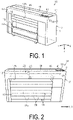
FIG. 1 is a perspective view illustrating a recording device according to an exemplary embodiment. -
FIG. 2 is a schematic view illustrating the recording device. -
FIG. 3 is a cross-sectional view of the recording device. -
FIG. 4 is a schematic view illustrating the recording device. -
FIG. 5 is a top view of the recording device. -
FIG. 6 is a perspective view illustrating the recording device when a cover member is at a closing position. -
FIG. 7 is a perspective view illustrating the recording device when the cover member is at an opening position. -
FIG. 8 is a perspective view illustrating a housing and a tray member. -
FIG. 9 is a schematic view for explaining a positional relationship between an operating unit and a near field communication sensor. -
FIG. 10 is a schematic view for explaining a positional relationship between an operating unit and a near field communication sensor in another example. -
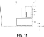
FIG. 11 is a schematic view for explaining a positional relationship between an operating unit and a near field communication sensor in yet another example. - One exemplary embodiment of a recording device as an example of a processing device will be described below with reference to the accompanying drawings. The recording device according to the present exemplary embodiment is, for example, an ink jet-type printer configured to discharge ink, which is an example of liquid, onto a medium such as paper, to perform printing.
- In the drawings, a direction of gravity is indicated by a Z-axis while assuming that the recording device is placed on a horizontal surface, and directions along the horizontal surface are indicated by an X-axis and a Y-axis. The X-, Y-, and Z-axes are orthogonal to each other. In the following description, a direction parallel to the X-axis is also referred to as a width direction X, and a direction parallel to the Y-axis is also referred to as a depth direction Y, and a direction parallel to the Z-axis is also referred to as a vertical direction Z.
- As illustrated in
FIG. 1 , arecording device 10, which is an example of the processing device, includes ahousing 11. Thehousing 11 has a substantially rectangular shape. Thehousing 11 includes anupper wall 16 and aside wall 17. Theside wall 17 includes afront wall 12, arear wall 13, afirst side wall 14, and asecond side wall 15. Thefront wall 12 is located farther in the depth direction Y than therear wall 13. Thesecond side wall 15 is located farther in the width direction X than thefirst side wall 14. Thesecond side wall 15 is coupled to an end portion of each of thefront wall 12 and therear wall 13 in the width direction X. Thefirst side wall 14 is coupled to an end portion of each of thefront wall 12 and therear wall 13 in a direction opposite the width direction X. Theupper wall 16 is coupled to an upper end of each of thefront wall 12, therear wall 13, thefirst side wall 14, and thesecond side wall 15. Theupper wall 16 may extend parallel to the horizontal surface. - As illustrated in
FIG. 2 , therecording device 10 may include aninstallation unit 19 on which acylindrical roll body 18 can be installed. Theroll body 18 is formed by winding arecording medium 20 around a core member 18a. A plurality of theroll bodies 18 can be installed on theinstallation unit 19. Both ends of eachroll body 18 in the width direction X are rotatably mounted on holding units (not illustrated) of theinstallation unit 19 respectively. Theinstallation unit 19 opens in a part in the vertical direction Z of thefront wall 12 of thehousing 11. Theinstallation unit 19 configures a part of an internal space of thehousing 11 in the vertical direction Z. - The
recording device 10 may include a plate-like support 21 inside thehousing 11. Thesupport 21 is located above theinstallation unit 19. A dimension in the width direction X of thesupport 21 is greater than a dimension in the width direction X of therecording medium 20. Thesupport 21 can support therecording medium 20 on an upper surface thereof. - As illustrated in
FIG. 3 , therecording device 10 may include afeeding unit 26 for feeding therecording medium 20, atransport unit 28 for transporting therecording medium 20 along atransport path 27 illustrated by a two-dot chain line in the figure, and acontrol unit 29. Thehousing 11 accommodates atransport path 27. Thetransport path 27 may include an upside of thesupport 21. Thetransport path 27 is coupled to adischarge port 12h that opens in thefront wall 12. - The
feeding unit 26 rotates theroll body 18 by driving of adrive motor 26a. As theroll body 18 rotates, therecording medium 20 is unwound from theroll body 18 and fed to thetransport path 27. - The
transport unit 28 may be provided with a plurality oftransport roller pairs 30. Thetransport roller pair 30 rotates while sandwiching therecording medium 20, thereby transporting therecording medium 20 in a transport direction D on thetransport path 27. The transport direction D is a direction along thetransport path 27. - The
control unit 29 may control various operations performed in therecording device 10. Thecontrol unit 29 can be constituted as α: one or more processors performing various types of processing in accordance with a computer program, β: one or more dedicated hardware circuits such as an application specific integrated circuit for performing at least some of the various types of processing, or y: a circuit including a combination thereof. The processor includes a CPU and memories such as a RAM and a ROM, and the memory is configured to store a program code or a command configured to cause the CPU to execute the processing. The memory, or a computer readable medium includes any readable medium accessible by a general purpose or special purpose computer. - As illustrated in
FIG. 3 , therecording device 10 includes arecording unit 22, which is an example of a processing unit. Therecording unit 22 is disposed inside thehousing 11. Therecording unit 22 may include acarriage 23 that moves in a scanning direction S, a rod-like guide shaft 24 extending in the width direction X, and a carriage motor 23a. The scanning direction S may be a direction parallel to the X-axis. Thecarriage 23 is supported by theguide shaft 24. Thecarriage 23 can reciprocate along theguide shaft 24 when the carriage motor 23a is driven. Thecarriage 23 and theguide shaft 24 are located spaced upward thesupport 21. - As illustrated in
FIG. 4 , therecording unit 22 includes arecording head 25 for performing recording on therecording medium 20. In other words, therecording device 10 includes therecording head 25. Therecording head 25 has anozzle surface 25b in which anozzle 25a opens. - On the
carriage 23, therecording head 25 is mounted. Therecording head 25 moves with thecarriage 23 to perform scanning in the scanning direction S. Therecording head 25 moves to positions above thesupport 21 and away from thesupport 21. Thenozzle surface 25b may be parallel to an upper surface of thesupport 21. Therecording head 25 may discharge liquid from thenozzle 25a onto therecording medium 20 on thesupport 21 to perform recording on therecording medium 20. - Note that, the transport direction D of the
transport path 27 on thesupport 21 is parallel to the Y-axis. The scanning direction S of therecording head 25 is parallel to the X-axis. Therefore, therecording head 25 can be said to perform scanning in a direction different from the transport direction D of therecording medium 20 to perform recording. - As illustrated in
FIG. 4 , therecording device 10 includes acap 31, which is an example of a maintenance member. Thecap 31 is disposed inside thehousing 11. Thecap 31 may be capable of reciprocating along the Z-axis by acap motor 32. As thecap motor 32 drives, thecap 31 moves between a separate position, which is a lower position, and a contact location, which is an upper position. When thecap 31 is at the contact position, thecap 31 contacts therecording head 25 that is stopped at a cap position. The cap position is a position of an end portion of a scanning region of therecording head 25 in the scanning direction S. - The
cap 31 is used for maintenance of therecording head 25. Thecap 31 covers thenozzle surface 25b to enclose an opening of thenozzle 25a of therecording head 25. In this manner, the maintenance in which thecap 31 encloses the opening of thenozzle 25a is referred to as capping. By the capping, drying of thenozzle 25a is suppressed. Thecap 31 may be configured to collectively enclose all thenozzles 25a that open in thenozzle surface 25b. - As illustrated in
FIG. 5 , therecording device 10 may include anoperating unit 33 operated by a user. The operatingunit 33 may be configured, for example, by a touch panel or the like, and may be used when the user inputs various types of information. The input of various types of information into the operatingunit 33 may be performed by the user touching various menus displayed on theoperation unit 33. Based on the input to the operatingunit 33 by the user, thecontrol unit 29 may control movement and stop of therecording head 25 by controlling driving of the carriage motor 23a. - The operating
unit 33 is disposed inside thehousing 11. The operatingunit 33 may be disposed on theupper wall 16 of thehousing 11. The operatingunit 33 may be disposed shifted in the width direction X from a center portion of thehousing 11 in the width direction X. - As illustrated in
FIG. 5 , therecording device 10 includes acover member 41 that covers theopening 11h located in thehousing 11 in an openable and closeable manner. Thecover member 41 and theopening 11h may be disposed on theupper wall 16 of thehousing 11. Thecover member 41 and theopening 11h may be disposed at respective positions biased in the width direction X from the center portion of theupper wall 16 in the width direction X. The operatingunit 33 may be aligned with thecover member 41 and theopening 11h in the depth direction Y. - A virtual plane having an opening edge of the
housing 11 as a periphery is referred to as an opening surface of theopening 11h. The opening surface of theopening 11h may be a horizontal surface orthogonal to the vertical direction Z. Thecover member 41 may have a flat plate shape that extends along the opening surface of theopening 11h. - The
housing 11 may include alarge opening 11r that is greater than theopening 11h, and alarge cover 45 that covers thelarge opening 11r. Theopening 11h and thecover member 41 may be disposed on theupper wall 16 in the width direction X so as to be aligned with thelarge opening 11r and thelarge cover 45. - As illustrated in
FIG. 6 , thecover member 41 may be transmissive. Thecover member 41 may include asupport portion 42 that supports thecover member 41 on theupper wall 16. The twosupport portions 42 are located along acover end portion 41a as an end portion of thecover member 41. Thesupport portion 42 supports thecover member 41 so as to be rotatable relative to thehousing 11, about a rotary shaft that extends parallel to thecover end portion 41a. That is, thecover member 41 may be rotationally movable with thecover end portion 41a of thecover member 41 as a rotation axis. Thecover member 41 may rotationally move to be movable to an opening position for opening theopening 11h and to a closing position for closing theopening 11h. Note that, a configuration may be adopted in which thecover member 41 can move to the opening position when thelarge cover 45 is at the opening position since a part of thecover member 41 overlaps thelarge cover 45, or the like. - As illustrated in
FIG. 7 , a portion of theupper wall 16 that constitutes theopening 11h and is located around theopening 11h is referred to as aperipheral wall portion 16a. Theperipheral wall portion 16a is located farther in the vertical direction Z than a portion of theupper wall 16 other than theperipheral wall portion 16a. A surface of thecover member 41 facing theopening 11h is referred to as a coverinner surface 41u, and a surface of thecover member 41 opposite to the coverinner surface 41u is referred to as a coverouter surface 41t. The coverouter surface 41t of thecover member 41 may be flush with a surface of a portion of theupper wall 16 other than theperipheral wall portion 16a. The coverinner surface 41u of thecover member 41 may be spaced apart from theperipheral wall portion 16a. - The
recording unit 22 is exposed to an exterior of thehousing 11 through theopening 11h of theupper wall 16. More specifically, when therecording head 25 in therecording unit 22 is at the cap position, thecarriage 23 is exposed to the exterior of thehousing 11 through theopening 11h. Also, when therecording head 25 moves from the cap position and therecording head 25 is no longer located above thecap 31, thecap 31 is exposed to the exterior of thehousing 11 through theopening 11h. - As illustrated in
FIG. 7 , therecording device 10 may include atray member 51 that overlaps theopening 11h from outside thehousing 11. Thetray member 51 may be disposed on thehousing 11 in a detachable manner. Attachment to thehousing 11 and removal from thehousing 11 of thetray member 51 may be performed by the user. - The
tray member 51 may be located above therecording head 25 and thecap 31. Therecording head 25 is movable in the scanning direction S by passing below thetray member 51. Thetray member 51 overlaps a part of theopening 11h in a direction opposite the width direction X. When thetray member 51 is attached to thehousing 11, and thetray member 51 overlaps a part of theopening 11h, thecarriage 23 is exposed to the exterior of thehousing 11 via a part of theopening 11h not overlapping thetray member 51. Note that, thetray member 51 may overlap theentire opening 11h. - As illustrated in
FIG. 8 , thetray member 51 may include a substantially rectangular box-shapedaccommodation portion 52 that opens upward, and a protrudingportion 53 that protrudes from an opening end of theaccommodation portion 52. Theaccommodation portion 52 includes a substantiallyrectangular bottom wall 54, and anextended wall 55 extending upward from a periphery of thebottom wall 54. Thetray member 51 may include anotch 56 obtained by cutting a part of each of theextended wall 55 and the protrudingportion 53. Thenotch 56 is located at an end portion of thetray member 51 in the depth direction Y, with thetray member 51 attached to theupper wall 16 of thehousing 11. - When the
tray member 51 is attached to theupper wall 16 of thehousing 11, the protrudingportion 53 is disposed on theupper wall 16 around theopening 11h, and thebottom wall 54 of theaccommodation portion 52 is located below the opening surface of theopening 11h. As a result, a lower portion of theaccommodation portion 52 including thebottom wall 54 is located below the opening surface of theopening 11h, in an orthogonal direction C orthogonal to the opening surface of theopening 11h. An upper portion of theaccommodation portion 52 including the opening end of theaccommodation portion 52, and the protrudingportion 53 are located between the opening surface of theopening 11h and thecover member 41 in the orthogonal direction C. Note that, the orthogonal direction C may be a direction parallel to the Z-axis direction. - As illustrated in
FIG. 7 , therecording device 10 includes a nearfield communication sensor 61 disposed in thehousing 11. The nearfield communication sensor 61 is a sensor capable of communicating with a communication terminal via Near Field Communication (NFC). By the user moving the communication terminal closer to the nearfield communication sensor 61, thecontrol unit 29 can receive various data from the communication terminal, and transmit various data to the communication terminal via the nearfield communication sensor 61. - The near
field communication sensor 61 may be disposed on thetray member 51, thereby disposed in thehousing 11 via thetray member 51. The nearfield communication sensor 61 disposed on thetray member 51 is accommodated in theaccommodation portion 52 of thetray member 51, and is disposed on thebottom wall 54. With the nearfield communication sensor 61 disposed on thetray member 51, attachment of thetray member 51 to theupper wall 16 of thehousing 11, and removal of thetray member 51 from theupper wall 16 are possible. After attaching thetray member 51 to theupper wall 16 of thehousing 11, attachment to and removal from theupper wall 16 such as disposition of the nearfield communication sensor 61 on thetray member 51, can be separately performed for thetray member 51 and the nearfield communication sensor 61. - By disposing the near
field communication sensor 61 on thetray member 51, the nearfield communication sensor 61 is located between the opening surface of theopening 11h and thecover member 41 in the orthogonal direction C, with thecover member 41 closing theopening 11h. By thecover member 41 being transmissive, the nearfield communication sensor 61 may be visible to the user with thecover member 41 closing theopening 11h. - The near
field communication sensor 61 may includewiring 61a extending from the nearfield communication sensor 61. Thewiring 61a may extend from the nearfield communication sensor 61 toward thecover end portion 41a of thecover member 41. Thewiring 61a may be coupled to thecontrol unit 29, for example. Various data may be transmitted and received between the nearfield communication sensor 61 and thecontrol unit 29 via thewiring 61a. Thewiring 61a may be coupled to thecontrol unit 29 through thenotch 56 of thetray member 51. - As illustrated in
FIG. 9 , the nearfield communication sensor 61 may be surrounded by theupper wall 16. Similar to the disposition of theopening 11h on thehousing 11, the nearfield communication sensor 61 may be disposed shifted in the width direction X from a center portion of thehousing 11 in width direction X. Note that, the operatingunit 33 is also disposed shifted in the width direction X from the center portion of thehousing 11 in the width direction X. The operatingunit 33 is not aligned with the nearfield communication sensor 61 in any direction of the width direction X different from the orthogonal direction C, and the depth direction Y different from the orthogonal direction C and the width direction X. - Next, actions of the present exemplary embodiment will be described.
- As illustrated in
FIG. 9 , theopening 11h in theupper wall 16 of thehousing 11 is used by the user to maintain therecording head 25 through theopening 11h, and can be used as a disposition space for the nearfield communication sensor 61. - The user may hold the communication terminal over the near
field communication sensor 61, with thecover member 41 closing theopening 11h.FIG. 9 illustrates a disposition region of the communication terminal by a two-dot chain line. For example, the communication terminal can be disposed on a surface of theupper wall 16 that includes a part farther in the depth direction Y than thecover member 41, as indicated by a first disposition region Ra. For example, the communication terminal can be disposed on the coverouter surface 41t of thecover member 41 that includes a part farther in the width direction X than an upside of the nearfield communication sensor 61, as indicated by a second disposition region Rb. - Effects of the present exemplary embodiment will now be described.
- (1) Because the
opening 11h exposes therecording unit 22 outside thehousing 11, the user can use theopening 11h for maintenance of therecording unit 22. The nearfield communication sensor 61 is located between the opening surface of theopening 11h and thecover member 41. Thus, in thehousing 11, an installation space for theopening 11h used for maintenance and thecover member 41 can also serve as an installation space for the nearfield communication sensor 61. Accordingly, installation of the nearfield communication sensor 61 inhousing 11 can be prevented from affecting an appearance of thehousing 11, since a new installation space for the nearfield communication sensor 61 need not be provided in thehousing 11. - (2) The
cover member 41 and theopening 11h are disposed on theupper wall 16 of thehousing 11. Accordingly, when the user places the communication terminal on theupper wall 16 of thehousing 11, data communication between the nearfield communication sensor 61 and the communication terminal is enabled while posture of the communication terminal is in a stable state. Accordingly, when data communication between the nearfield communication sensor 61 and the communication terminal is performed, the communication terminal can be prevented from falling out of thehousing 11. - (3) The near
field communication sensor 61 is disposed on thetray member 51. As such, the user can remove thetray member 51 from thehousing 11 to space the nearfield communication sensor 61 from theopening 11h of thehousing 11. Accordingly, the user can perform maintenance of therecording unit 22 by widely using theopening 11h of thehousing 11, and thus work efficiency for the user can be improved. - (4) Because both the operating
unit 33 and the nearfield communication sensor 61 are located biased in the width direction X from the center portion of thehousing 11, the operatingunit 33 and the nearfield communication sensor 61 are closer to each other in thehousing 11. As such, a time difference can be decreased between an operation by the user for holding the communication terminal over the nearfield communication sensor 61, and an operation by the user for operating the operatingunit 33. Accordingly, the work efficiency for the user can be improved. - (5) The
operating unit 33 is present at a position not aligned with the nearfield communication sensor 61 in any direction of the width direction X different from the orthogonal direction C, and the depth direction Y different from the orthogonal direction C and the width direction X. In thehousing 11, the operatingunit 33 is not disposed on a space shifted in the width direction X, and on a space shifted in the depth direction Y with respect to the nearfield communication sensor 61. As a result, when the user holds the communication terminal over the nearfield communication sensor 61, the operatingunit 33 is less likely to be hidden by the communication terminal. Accordingly, operability of the operatingunit 33 for the user can be improved. - (6) The
cover member 41 can rotationally move with thecover end portion 41a of thecover member 41 as the rotation axis, to be movable to the opening position for opening theopening 11h and to the closing position for closing theopening 11h. The nearfield communication sensor 61 includes thewiring 61a that extends from the nearfield communication sensor 61 toward thecover end portion 41a. Thus, as thecover member 41 opens or closes, thewiring 61a of the nearfield communication sensor 61 can be prevented from being sandwiched between thecover member 41 and thehousing 11. - (7) The
cover member 41 is transmissive. The nearfield communication sensor 61 is visible to the user with thecover member 41 closing theopening 11h. Thus, with thecover member 41 closing theopening 11h, the user can check that the nearfield communication sensor 61 is attached to thehousing 11. Accordingly, there is no need to dispose a notification unit in therecording device 10 that notifies the user that the nearfield communication sensor 61 is attached to thehousing 11.
The exemplary embodiment described above may be modified as follows. The exemplary embodiment described above and modified examples thereof to be described below may be implemented in combination within a range in which a technical contradiction does not arise.
Thecover member 41 and theopening 11h may be disposed on theside wall 17 of thehousing 11.
As illustrated inFIG. 10 , the operatingunit 33 may be aligned with the nearfield communication sensor 61 in the width direction X different from the orthogonal direction C. As illustrated inFIG. 11 , the operatingunit 33 may be aligned with the nearfield communication sensor 61 in the depth direction Y different from the orthogonal direction C and the width direction X. In other words, the operatingunit 33 may be aligned with the nearfield communication sensor 61 in one direction of the width direction X and the depth direction Y. Note that, in each ofFIGS. 10 and11 , a disposition region of the communication terminal is illustrated by a two-dot chain line.
According to the modified examples described above, the following effects can be achieved in addition to the effects of (1) to (4), (6), and (7) of the exemplary embodiment described above. - (8) The
operating unit 33 is aligned with the nearfield communication sensor 61 in one direction of the width direction X and the depth direction Y. As a result, when the user holds the communication terminal over the nearfield communication sensor 61, the communication terminal can be aligned with the operatingunit 33, and thus the operatingunit 33 is less likely to be hidden by the communication terminal. Accordingly, operability of the operatingunit 33 for the user can be improved.
The nearfield communication sensor 61 may be attached to the coverinner surface 41u facing theopening 11h in thecover member 41.
According to the modified example described above, the following effects can be achieved in addition to the effects of the exemplary embodiment described above and the modified examples described above. - (9) The near
field communication sensor 61 is attached to the coverinner surface 41u facing theopening 11h in thecover member 41. As such, because the nearfield communication sensor 61 is displaced with thecover member 41, opening or closing of thecover member 41 can move the nearfield communication sensor 61. Thus, apart from an operation for bringing thecover member 41 into an open state, an operation by the user for moving the nearfield communication sensor 61 is unnecessary, so a work load on the user can be reduced. - In the above modified example, the
tray member 51 may be attached to the coverinner surface 41u, and the nearfield communication sensor 61 may be accommodated in thetray member 51, to attach the nearfield communication sensor 61 to the coverinner surface 41u. In the above modified example, the nearfield communication sensor 61 itself may be attached to the coverinner surface 41u without attaching thetray member 51 to the coverinner surface 41u. - The disposition of the
tray member 51 on thehousing 11 may be omitted. In this case, the nearfield communication sensor 61 is disposed on thehousing 11 without being disposed on thetray member 51. - In the width direction X, the operating
unit 33 may be disposed on one side with the center portion of thehousing 11 interposed, and the nearfield communication sensor 61 may be disposed on another side. - The
wiring 61a of the nearfield communication sensor 61 may extend from the nearfield communication sensor 61 so as to be away from thecover end portion 41a of thecover member 41. - The opening or closing operation of the
opening 11h by thecover member 41 is not limited to rotationally moving with thecover end portion 41a of thecover member 41 as the rotation axis. For example, thecover member 41 may be configured to be removable from thehousing 11. In this case, thecover member 41 is removed from thehousing 11 by the user to open theopening 11h. Thecover member 41 is attached to thehousing 11 by the user to close theopening 11h. - The
cover member 41 need not be transmissive. In this case, a notification unit may be disposed in therecording device 10 that notifies the user of whether the nearfield communication sensor 61 is disposed in thehousing 11 or not. The user can check the disposition of the nearfield communication sensor 61 in thehousing 11 without visually recognizing the nearfield communication sensor 61 disposed in thehousing 11 by checking the notification unit. - A processing unit other than the
recording unit 22 may be exposed to the exterior of thehousing 11 through theopening 11h. Examples of the processing unit in this modified example include thefeeding unit 26, thetransport unit 28, and thecontrol unit 29. Also, a cutter for cutting roll paper or the like, and a waste liquid tank for accommodating liquid removed from thenozzle surface 25b by maintenance, and the like can also be employed as the processing unit. - The
cover member 41, the nearfield communication sensor 61, thetray member 51, and the operatingunit 33 in the exemplary embodiment described above and the modified examples described above can also be employed in processing devices other than therecording device 10. In this case, the processing unit is disposed inside thehousing 11. The processing unit is exposed to the exterior of thehousing 11 through theopening 11h. The user can use theopening 11h for maintenance of the processing unit. In this modification example, effects similar to those in the above-described exemplary embodiment and modified examples can also be achieved. Note that, examples of the combination of the processing device and the processing unit in this modified example include the following combinations. In other words, the processing device may be a projector, and the processing unit may be a lamp. The processing device may be a printer or a post-processor installed with a printer, and the processing unit may be a cutter for cutting roll paper or the like. The processing device may be a scanner for moving and reading a target object such as paper, and the processing unit may be a roller for feeding the target object. - The
recording device 10 may be a liquid jet device that jets or discharges other liquid other than ink and performs recording. Examples of a state of the liquid discharged from the liquid jet device as a small amount of droplets include granules, tears, and string-like tails. As the liquid described herein, it is sufficient that a material that can be jetted from the liquid jet device is used. For example, it is sufficient that the liquid is a substance in a state of a liquid phase, and examples include fluid bodies such as a liquid body with high or low viscosity, sol, gel water, other inorganic solvents, organic solvents, solutions, liquid resins, liquid metals, and metallic melts. Examples of the liquid include not only liquid as one state of a substance, but also particles of functional material consisting of solid substances such as pigments or metal particles dissolved, dispersed, or mixed in a solvent. Representative examples of the liquid include inks, liquid crystals, and the like described in the exemplary embodiment described above. Here, the ink includes various liquid compositions such as a general aqueous ink and a solvent ink, a gel ink, or a hot-melt ink. Specific examples of the liquid jet device include, for example, a device that jets liquid including materials such as an electrode material and a color material used in manufacture of liquid crystal displays, electroluminescent displays, surface emitting displays, color filters, and the like in a dispersed or dissolved form. The liquid jet device may be a device that jets bioorganic substances used for biochip manufacturing, a device used as a precision pipette and jetting liquid to be a sample, a printing apparatus, a micro dispenser, or the like. The liquid jet device may be a device jetting lubricant to a precision machine such as a clock or a camera in a pinpoint manner, and a device jetting transparent resin liquid such as ultraviolet cure resin or the like on a substrate for forming a tiny hemispherical lens, an optical lens, or the like used for an optical communication element and the like. The liquid jet device may be a device that jets an etching solution, such as acid or alkali, to etch a substrate or the like. - Hereinafter, technical concepts and effects thereof that are understood from the above-described exemplary embodiments and modified examples will be described.
- (A) A processing device includes a housing, a processing unit disposed inside the housing, a cover member configured to cover an opening located in the housing in an openable and closeable manner, and a near field communication sensor disposed in the housing, wherein the processing unit is exposed to an exterior of the housing through the opening, and the near field communication sensor is, with the opening closed by the cover member, located between the opening surface and the cover member in an orthogonal direction orthogonal to an opening surface of the opening.
According to this configuration, the opening exposes the processing unit to an exterior of the housing, so a user can use the opening for maintenance of the processing unit. The near field communication sensor is located between the opening surface of the opening and the cover member. Thus, in the housing, an installation space for the opening used for maintenance and the cover member can also serve as an installation space for the near field communication sensor. Accordingly, installation of the near field communication sensor in housing can be prevented from affecting an appearance of the housing, since a new installation space for the near field communication sensor need not be provided in the housing. - (B) In a processing device, the cover member and the opening may be disposed on an upper wall of the housing.
According to this configuration, when the user places the communication terminal on the upper wall of the housing, data communication between the near field communication sensor and the communication terminal is enabled while posture of the communication terminal is in a stable state. Accordingly, when data communication between the near field communication sensor and the communication terminal is performed, the communication terminal can be prevented from falling out of the housing. - (C) In a processing device, the cover member and the opening may be disposed on a side wall of the housing.
- (D) In a processing device, a tray member that overlaps the opening from outside the housing and is detachably disposed on the housing may be provided, and the near field communication sensor may be disposed on the housing via the tray member.
According to this configuration, the user can remove the tray member from the housing to space the near field communication sensor from the opening of the housing. Accordingly, the user can perform maintenance of the processing unit by widely using the opening of the housing, and thus work efficiency for the user can be improved. - (E) A processing device may include an operating unit disposed on the housing and operated by a user, and the operating unit and the near field communication sensor may be disposed shifted in a width direction from a center portion of the housing in the width direction different from the orthogonal direction.
According to this configuration, because both the operating unit and the near field communication sensor are located biased in the width direction from the center portion of the housing, so that the operating unit and the near field communication sensor are closer to each other in the housing. As such, a time difference can be decreased between an operation by the user for holding the communication terminal over the near field communication sensor, and an operation by the user for operating the operating unit. Accordingly, the work efficiency for the user can be improved. - (F) A processing device may include an operating unit disposed on the housing and operated by a user, and the operating unit may be present at a position that is not aligned with the near field communication sensor in any direction of a width direction different from the orthogonal direction and a depth direction different from the orthogonal direction and the width direction.
According to this configuration, in the housing, the operating unit is not disposed on a space shifted in the width direction, and a space shifted in the depth direction with respect to the near field communication sensor. As a result, when the user holds the communication terminal over the near field communication sensor, the operating unit is less likely to be hidden by the communication terminal. Accordingly, operability of the operating unit for the user can be improved. - (G) A processing device may include an operating unit disposed on the housing and operated by a user, and the operating unit may be aligned with the near field communication sensor in any one direction of a width direction different from the orthogonal direction and a depth direction different from the orthogonal direction and the width direction.
According to this configuration, the operating unit is aligned with the near field communication sensor in one direction of the width direction and the depth direction. As a result, when the user holds the communication terminal over the near field communication sensor, the communication terminal can be aligned with the operating unit, and thus the operating unit is less likely to be hidden by the communication terminal. Accordingly, operability of the operating unit for the user can be improved. - (H) In a processing device, the near field communication sensor may be attached to an inner surface of the cover member facing the opening.
According to this configuration, because the near field communication sensor is displaced with the cover member, opening or closing of the cover member can move the near field communication sensor. Thus, apart from an operation for bringing the cover member into an open state, an operation by the user for moving the near field communication sensor is unnecessary, so a work load on the user can be reduced. - (I) In a processing device, the cover member may rotationally move with an end portion of the cover member as a rotation axis, to be movable to an opening position for opening the opening and to a closing position for closing the opening, and the near field communication sensor may include wiring extending from the near field communication sensor toward the end portion.
According to this configuration, as the cover member opens or closes, the wiring of the near field communication sensor can be prevented from being sandwiched between the cover member and the housing. - (J) In a processing device, the cover member may be transmissive, and the near field communication sensor may be visible to a user with the opening closed by the cover member.
According to this configuration, with the opening closed by the cover member, the user can check that the near field communication sensor is attached to the housing. Accordingly, there is no need to dispose a notification unit in the processing device that notifies the user that the near field communication sensor is attached to the housing. - (K) A recording device includes a housing, a recording head configured to perform scanning in a scanning direction different from a transport direction of a recording medium to perform recording, a maintenance member disposed inside the housing, and used for maintenance of the recording head, a cover member configured to cover an opening located in the housing in an openable and closeable manner, and a near field communication sensor disposed in the housing, wherein the maintenance member is exposed to an exterior of the housing through the opening, and the near field communication sensoris, with the opening closed by the cover member, located between the opening surface and the cover member in an orthogonal direction orthogonal to an opening surface of the opening.
- According to this configuration, the same effect as the processing device described above can be obtained.
Claims (8)
- A processing device, comprising:a housing;a processing unit disposed inside the housing;a cover member configured to cover openably and closeably an opening located at an upper wall of the housing;a near field communication sensor disposed at the housing;a tray member overlapping the opening from outside the housing, detachably disposed at the housing, and holding the near field communication sensor so that the near field communication sensor is disposed inside the housing, whereinthe processing unit is exposed to an exterior of the housing through the opening,the near field communication sensor held by the tray member is, with the opening closed by the cover member, located between the opening surface and the cover member in an orthogonal direction orthogonal to an opening surface of the opening, andwith the cover member closed, an outer surface of the cover member, and a region of an upper surface of the housing other than the cover member are flush.
- The processing device according to claim 1, comprising:
an operating unit disposed at the housing and operated by a user, wherein
the operating unit and the near field communication sensor are disposed shifted in a width direction, different from the orthogonal direction, from a center portion of the housing in the width direction. - The processing device according to any one of the preceding claims, comprising:
an operating unit disposed at the housing and operated by a user, wherein
the operating unit is present at a position that is not aligned with the near field communication sensor in any direction of a width direction different from the orthogonal direction and a depth direction different from the orthogonal direction and the width direction. - The processing device according to any one of the preceding claims, comprising:
an operating unit disposed at the housing and operated by a user, wherein
the operating unit is aligned with the near field communication sensor in any one direction of a width direction different from the orthogonal direction, and a depth direction different from the orthogonal direction and the width direction. - The processing device according to any one of the preceding claims, wherein
the near field communication sensor is attached to an inner surface of the cover member facing the opening. - The processing device according to any one of the preceding claims, whereinthe cover member is configured to move to an opening position for opening the opening and to a closing position for closing the opening, by rotationally moving with an end portion of the cover member as a rotation axis, andthe near field communication sensor includes wiring extending from the near field communication sensor toward the end portion.
- The processing device according to any one of the preceding claims, whereinthe cover member is transmissive, andthe near field communication sensor is visible by a user with the opening closed by the cover member.
- A recording device, comprising:a housing;a recording head configured to perform scanning in a scanning direction different from a transport direction of a recording medium to perform recording;a cover member configured to cover openably and closeably an opening located at an upper wall of the housing;a near field communication sensor disposed at the housing; anda tray member overlapping the opening from outside the housing, detachably disposed at the housing, and holding the near field communication sensor so that the near field communication sensor is disposed inside the housing, whereinthe recording head that is located at a maintenance position is exposed to an exterior of the housing through the opening,the near field communication sensor held by the tray member is, with the opening closed by the cover member, located between the opening surface and the cover member in an orthogonal direction orthogonal to an opening surface of the opening, andwith the cover member closed, an outer surface of the cover member, and a region of an upper surface of the housing other than the cover member are flush.
Applications Claiming Priority (1)
| Application Number | Priority Date | Filing Date | Title |
|---|---|---|---|
| JP2020203586A JP7001140B1 (en) | 2020-12-08 | 2020-12-08 | Processing equipment and recording equipment |
Publications (2)
| Publication Number | Publication Date |
|---|---|
| EP4011631A1 true EP4011631A1 (en) | 2022-06-15 |
| EP4011631B1 EP4011631B1 (en) | 2023-09-27 |
Family
ID=78414233
Family Applications (1)
| Application Number | Title | Priority Date | Filing Date |
|---|---|---|---|
| EP21204309.5A Active EP4011631B1 (en) | 2020-12-08 | 2021-10-22 | Processing device and recording device |
Country Status (4)
| Country | Link |
|---|---|
| US (1) | US12358313B2 (en) |
| EP (1) | EP4011631B1 (en) |
| JP (1) | JP7001140B1 (en) |
| CN (1) | CN114619761B (en) |
Citations (8)
| Publication number | Priority date | Publication date | Assignee | Title |
|---|---|---|---|---|
| GB2350220A (en) * | 1999-03-12 | 2000-11-22 | Ito Inc Uk Ltd | Inkjet printing apparatus |
| US20130082883A1 (en) * | 2011-09-30 | 2013-04-04 | Anthony S. Montevirgen | Portable electronic device housing having insert molding around antenna |
| US20150181063A1 (en) * | 2013-12-24 | 2015-06-25 | Brother Kogyo Kabushiki Kaisha | Image Forming Apparatus |
| US20150280306A1 (en) * | 2014-03-27 | 2015-10-01 | Brother Kogyo Kabushiki Kaisha | Communication device provided with antenna for near field wireless communication |
| JP2015189107A (en) * | 2014-03-28 | 2015-11-02 | ブラザー工業株式会社 | Image forming device |
| JP2016167232A (en) | 2015-03-10 | 2016-09-15 | 東芝テック株式会社 | Printer and program |
| WO2018028483A1 (en) * | 2016-08-08 | 2018-02-15 | 珠海赛纳打印科技股份有限公司 | Image formation apparatus |
| JP2020203586A (en) | 2019-06-18 | 2020-12-24 | ダイハツ工業株式会社 | Vehicle structure |
Family Cites Families (18)
| Publication number | Priority date | Publication date | Assignee | Title |
|---|---|---|---|---|
| JP2006056017A (en) * | 2004-08-17 | 2006-03-02 | Canon Inc | Image forming apparatus |
| JP4632418B2 (en) * | 2004-11-01 | 2011-02-16 | キヤノン株式会社 | Image input / output device |
| JP4289375B2 (en) * | 2006-06-30 | 2009-07-01 | ブラザー工業株式会社 | Image forming apparatus |
| JP4420070B2 (en) * | 2007-06-20 | 2010-02-24 | ブラザー工業株式会社 | Image forming apparatus |
| JP5593709B2 (en) * | 2010-01-26 | 2014-09-24 | 株式会社リコー | Image processing device |
| US20130155450A1 (en) * | 2011-12-19 | 2013-06-20 | Brother Kogyo Kabushiki Kaisha | Recording apparatus having a plurality of antennas |
| JP2014004755A (en) * | 2012-06-25 | 2014-01-16 | Brother Ind Ltd | Recording apparatus |
| JP2014096717A (en) * | 2012-11-09 | 2014-05-22 | Brother Ind Ltd | Image forming apparatus |
| JP2016091083A (en) * | 2014-10-30 | 2016-05-23 | セイコーエプソン株式会社 | Print control apparatus, print control method, and program |
| JP6606895B2 (en) * | 2015-07-16 | 2019-11-20 | セイコーエプソン株式会社 | Electronic equipment, electronic equipment unit and display |
| JP2017087462A (en) * | 2015-11-04 | 2017-05-25 | 船井電機株式会社 | Electronic equipment |
| WO2018004657A1 (en) * | 2016-07-01 | 2018-01-04 | Hewlett-Packard Development Company, L.P. | Printing device dashboard |
| JP7134596B2 (en) * | 2017-03-30 | 2022-09-12 | キヤノン株式会社 | image forming device |
| JP6947203B2 (en) * | 2018-04-17 | 2021-10-13 | ブラザー工業株式会社 | Image forming device |
| JP7362247B2 (en) * | 2018-12-12 | 2023-10-17 | キヤノン株式会社 | Image forming device |
| JP7238478B2 (en) * | 2019-03-04 | 2023-03-14 | ブラザー工業株式会社 | image forming device |
| CN211567374U (en) * | 2019-09-26 | 2020-09-25 | 武汉理工大学 | An outdoor printer with protective device based on wireless communication module |
| WO2021230396A1 (en) * | 2020-05-13 | 2021-11-18 | 엘지전자 주식회사 | Display device |
-
2020
- 2020-12-08 JP JP2020203586A patent/JP7001140B1/en active Active
-
2021
- 2021-09-14 US US17/447,634 patent/US12358313B2/en active Active
- 2021-10-22 EP EP21204309.5A patent/EP4011631B1/en active Active
- 2021-12-07 CN CN202111483086.4A patent/CN114619761B/en active Active
Patent Citations (8)
| Publication number | Priority date | Publication date | Assignee | Title |
|---|---|---|---|---|
| GB2350220A (en) * | 1999-03-12 | 2000-11-22 | Ito Inc Uk Ltd | Inkjet printing apparatus |
| US20130082883A1 (en) * | 2011-09-30 | 2013-04-04 | Anthony S. Montevirgen | Portable electronic device housing having insert molding around antenna |
| US20150181063A1 (en) * | 2013-12-24 | 2015-06-25 | Brother Kogyo Kabushiki Kaisha | Image Forming Apparatus |
| US20150280306A1 (en) * | 2014-03-27 | 2015-10-01 | Brother Kogyo Kabushiki Kaisha | Communication device provided with antenna for near field wireless communication |
| JP2015189107A (en) * | 2014-03-28 | 2015-11-02 | ブラザー工業株式会社 | Image forming device |
| JP2016167232A (en) | 2015-03-10 | 2016-09-15 | 東芝テック株式会社 | Printer and program |
| WO2018028483A1 (en) * | 2016-08-08 | 2018-02-15 | 珠海赛纳打印科技股份有限公司 | Image formation apparatus |
| JP2020203586A (en) | 2019-06-18 | 2020-12-24 | ダイハツ工業株式会社 | Vehicle structure |
Also Published As
| Publication number | Publication date |
|---|---|
| CN114619761A (en) | 2022-06-14 |
| EP4011631B1 (en) | 2023-09-27 |
| US20220176721A1 (en) | 2022-06-09 |
| JP2022090959A (en) | 2022-06-20 |
| US12358313B2 (en) | 2025-07-15 |
| CN114619761B (en) | 2026-02-27 |
| JP7001140B1 (en) | 2022-01-19 |
Similar Documents
| Publication | Publication Date | Title |
|---|---|---|
| JP6307887B2 (en) | Liquid container and printer | |
| JP6492393B2 (en) | Liquid injection system | |
| CN113370659B (en) | Liquid ejection device | |
| WO2016199420A1 (en) | Liquid ejection device, tank unit, printer | |
| JP2017113969A (en) | printer | |
| JP2014094536A (en) | Liquid ejector | |
| JP2018140549A (en) | printer | |
| US10967637B2 (en) | Liquid ejecting apparatus | |
| JP2015134486A (en) | Liquid storage container | |
| JP2017001249A (en) | Liquid ejector | |
| EP4011631B1 (en) | Processing device and recording device | |
| JP2018008412A (en) | Cap, printer | |
| US10843471B2 (en) | Liquid ejection apparatus | |
| JP2015134485A (en) | liquid supply device | |
| JP2012011573A (en) | Recording device | |
| JP5458600B2 (en) | Fluid ejection device | |
| JP6201372B2 (en) | Recording device | |
| JP2018140548A (en) | printer | |
| JP2011161795A (en) | Liquid ejection device | |
| JP2014034182A (en) | Liquid injection device | |
| JP2018001530A (en) | Ink storage device, and printer | |
| JP7600643B2 (en) | Recording device | |
| JP6672783B2 (en) | Tank unit, printer | |
| JP2019142239A (en) | Liquid injection device | |
| JP2016132109A (en) | Liquid supply unit, liquid injection system |
Legal Events
| Date | Code | Title | Description |
|---|---|---|---|
| PUAI | Public reference made under article 153(3) epc to a published international application that has entered the european phase |
Free format text: ORIGINAL CODE: 0009012 |
|
| STAA | Information on the status of an ep patent application or granted ep patent |
Free format text: STATUS: THE APPLICATION HAS BEEN PUBLISHED |
|
| AK | Designated contracting states |
Kind code of ref document: A1 Designated state(s): AL AT BE BG CH CY CZ DE DK EE ES FI FR GB GR HR HU IE IS IT LI LT LU LV MC MK MT NL NO PL PT RO RS SE SI SK SM TR |
|
| STAA | Information on the status of an ep patent application or granted ep patent |
Free format text: STATUS: REQUEST FOR EXAMINATION WAS MADE |
|
| 17P | Request for examination filed |
Effective date: 20221104 |
|
| RBV | Designated contracting states (corrected) |
Designated state(s): AL AT BE BG CH CY CZ DE DK EE ES FI FR GB GR HR HU IE IS IT LI LT LU LV MC MK MT NL NO PL PT RO RS SE SI SK SM TR |
|
| GRAP | Despatch of communication of intention to grant a patent |
Free format text: ORIGINAL CODE: EPIDOSNIGR1 |
|
| STAA | Information on the status of an ep patent application or granted ep patent |
Free format text: STATUS: GRANT OF PATENT IS INTENDED |
|
| INTG | Intention to grant announced |
Effective date: 20230418 |
|
| GRAS | Grant fee paid |
Free format text: ORIGINAL CODE: EPIDOSNIGR3 |
|
| GRAA | (expected) grant |
Free format text: ORIGINAL CODE: 0009210 |
|
| STAA | Information on the status of an ep patent application or granted ep patent |
Free format text: STATUS: THE PATENT HAS BEEN GRANTED |
|
| AK | Designated contracting states |
Kind code of ref document: B1 Designated state(s): AL AT BE BG CH CY CZ DE DK EE ES FI FR GB GR HR HU IE IS IT LI LT LU LV MC MK MT NL NO PL PT RO RS SE SI SK SM TR |
|
| REG | Reference to a national code |
Ref country code: GB Ref legal event code: FG4D |
|
| REG | Reference to a national code |
Ref country code: CH Ref legal event code: EP |
|
| REG | Reference to a national code |
Ref country code: DE Ref legal event code: R096 Ref document number: 602021005431 Country of ref document: DE |
|
| REG | Reference to a national code |
Ref country code: IE Ref legal event code: FG4D |
|
| REG | Reference to a national code |
Ref country code: LT Ref legal event code: MG9D |
|
| PG25 | Lapsed in a contracting state [announced via postgrant information from national office to epo] |
Ref country code: GR Free format text: LAPSE BECAUSE OF FAILURE TO SUBMIT A TRANSLATION OF THE DESCRIPTION OR TO PAY THE FEE WITHIN THE PRESCRIBED TIME-LIMIT Effective date: 20231228 |
|
| PG25 | Lapsed in a contracting state [announced via postgrant information from national office to epo] |
Ref country code: SE Free format text: LAPSE BECAUSE OF FAILURE TO SUBMIT A TRANSLATION OF THE DESCRIPTION OR TO PAY THE FEE WITHIN THE PRESCRIBED TIME-LIMIT Effective date: 20230927 Ref country code: RS Free format text: LAPSE BECAUSE OF FAILURE TO SUBMIT A TRANSLATION OF THE DESCRIPTION OR TO PAY THE FEE WITHIN THE PRESCRIBED TIME-LIMIT Effective date: 20230927 Ref country code: NO Free format text: LAPSE BECAUSE OF FAILURE TO SUBMIT A TRANSLATION OF THE DESCRIPTION OR TO PAY THE FEE WITHIN THE PRESCRIBED TIME-LIMIT Effective date: 20231227 Ref country code: LV Free format text: LAPSE BECAUSE OF FAILURE TO SUBMIT A TRANSLATION OF THE DESCRIPTION OR TO PAY THE FEE WITHIN THE PRESCRIBED TIME-LIMIT Effective date: 20230927 Ref country code: LT Free format text: LAPSE BECAUSE OF FAILURE TO SUBMIT A TRANSLATION OF THE DESCRIPTION OR TO PAY THE FEE WITHIN THE PRESCRIBED TIME-LIMIT Effective date: 20230927 Ref country code: HR Free format text: LAPSE BECAUSE OF FAILURE TO SUBMIT A TRANSLATION OF THE DESCRIPTION OR TO PAY THE FEE WITHIN THE PRESCRIBED TIME-LIMIT Effective date: 20230927 Ref country code: GR Free format text: LAPSE BECAUSE OF FAILURE TO SUBMIT A TRANSLATION OF THE DESCRIPTION OR TO PAY THE FEE WITHIN THE PRESCRIBED TIME-LIMIT Effective date: 20231228 Ref country code: FI Free format text: LAPSE BECAUSE OF FAILURE TO SUBMIT A TRANSLATION OF THE DESCRIPTION OR TO PAY THE FEE WITHIN THE PRESCRIBED TIME-LIMIT Effective date: 20230927 |
|
| REG | Reference to a national code |
Ref country code: NL Ref legal event code: MP Effective date: 20230927 |
|
| REG | Reference to a national code |
Ref country code: AT Ref legal event code: MK05 Ref document number: 1615046 Country of ref document: AT Kind code of ref document: T Effective date: 20230927 |
|
| PG25 | Lapsed in a contracting state [announced via postgrant information from national office to epo] |
Ref country code: NL Free format text: LAPSE BECAUSE OF FAILURE TO SUBMIT A TRANSLATION OF THE DESCRIPTION OR TO PAY THE FEE WITHIN THE PRESCRIBED TIME-LIMIT Effective date: 20230927 |
|
| PG25 | Lapsed in a contracting state [announced via postgrant information from national office to epo] |
Ref country code: IS Free format text: LAPSE BECAUSE OF FAILURE TO SUBMIT A TRANSLATION OF THE DESCRIPTION OR TO PAY THE FEE WITHIN THE PRESCRIBED TIME-LIMIT Effective date: 20240127 |
|
| PG25 | Lapsed in a contracting state [announced via postgrant information from national office to epo] |
Ref country code: AT Free format text: LAPSE BECAUSE OF FAILURE TO SUBMIT A TRANSLATION OF THE DESCRIPTION OR TO PAY THE FEE WITHIN THE PRESCRIBED TIME-LIMIT Effective date: 20230927 |
|
| PG25 | Lapsed in a contracting state [announced via postgrant information from national office to epo] |
Ref country code: ES Free format text: LAPSE BECAUSE OF FAILURE TO SUBMIT A TRANSLATION OF THE DESCRIPTION OR TO PAY THE FEE WITHIN THE PRESCRIBED TIME-LIMIT Effective date: 20230927 |
|
| PG25 | Lapsed in a contracting state [announced via postgrant information from national office to epo] |
Ref country code: SM Free format text: LAPSE BECAUSE OF FAILURE TO SUBMIT A TRANSLATION OF THE DESCRIPTION OR TO PAY THE FEE WITHIN THE PRESCRIBED TIME-LIMIT Effective date: 20230927 Ref country code: RO Free format text: LAPSE BECAUSE OF FAILURE TO SUBMIT A TRANSLATION OF THE DESCRIPTION OR TO PAY THE FEE WITHIN THE PRESCRIBED TIME-LIMIT Effective date: 20230927 Ref country code: IS Free format text: LAPSE BECAUSE OF FAILURE TO SUBMIT A TRANSLATION OF THE DESCRIPTION OR TO PAY THE FEE WITHIN THE PRESCRIBED TIME-LIMIT Effective date: 20240127 Ref country code: ES Free format text: LAPSE BECAUSE OF FAILURE TO SUBMIT A TRANSLATION OF THE DESCRIPTION OR TO PAY THE FEE WITHIN THE PRESCRIBED TIME-LIMIT Effective date: 20230927 Ref country code: EE Free format text: LAPSE BECAUSE OF FAILURE TO SUBMIT A TRANSLATION OF THE DESCRIPTION OR TO PAY THE FEE WITHIN THE PRESCRIBED TIME-LIMIT Effective date: 20230927 Ref country code: CZ Free format text: LAPSE BECAUSE OF FAILURE TO SUBMIT A TRANSLATION OF THE DESCRIPTION OR TO PAY THE FEE WITHIN THE PRESCRIBED TIME-LIMIT Effective date: 20230927 Ref country code: AT Free format text: LAPSE BECAUSE OF FAILURE TO SUBMIT A TRANSLATION OF THE DESCRIPTION OR TO PAY THE FEE WITHIN THE PRESCRIBED TIME-LIMIT Effective date: 20230927 Ref country code: SK Free format text: LAPSE BECAUSE OF FAILURE TO SUBMIT A TRANSLATION OF THE DESCRIPTION OR TO PAY THE FEE WITHIN THE PRESCRIBED TIME-LIMIT Effective date: 20230927 Ref country code: PT Free format text: LAPSE BECAUSE OF FAILURE TO SUBMIT A TRANSLATION OF THE DESCRIPTION OR TO PAY THE FEE WITHIN THE PRESCRIBED TIME-LIMIT Effective date: 20240129 |
|
| PG25 | Lapsed in a contracting state [announced via postgrant information from national office to epo] |
Ref country code: PL Free format text: LAPSE BECAUSE OF FAILURE TO SUBMIT A TRANSLATION OF THE DESCRIPTION OR TO PAY THE FEE WITHIN THE PRESCRIBED TIME-LIMIT Effective date: 20230927 Ref country code: IT Free format text: LAPSE BECAUSE OF FAILURE TO SUBMIT A TRANSLATION OF THE DESCRIPTION OR TO PAY THE FEE WITHIN THE PRESCRIBED TIME-LIMIT Effective date: 20230927 |
|
| REG | Reference to a national code |
Ref country code: BE Ref legal event code: MM Effective date: 20231031 |
|
| PG25 | Lapsed in a contracting state [announced via postgrant information from national office to epo] |
Ref country code: LU Free format text: LAPSE BECAUSE OF NON-PAYMENT OF DUE FEES Effective date: 20231022 |
|
| PG25 | Lapsed in a contracting state [announced via postgrant information from national office to epo] |
Ref country code: LU Free format text: LAPSE BECAUSE OF NON-PAYMENT OF DUE FEES Effective date: 20231022 |
|
| REG | Reference to a national code |
Ref country code: DE Ref legal event code: R097 Ref document number: 602021005431 Country of ref document: DE |
|
| PG25 | Lapsed in a contracting state [announced via postgrant information from national office to epo] |
Ref country code: MC Free format text: LAPSE BECAUSE OF FAILURE TO SUBMIT A TRANSLATION OF THE DESCRIPTION OR TO PAY THE FEE WITHIN THE PRESCRIBED TIME-LIMIT Effective date: 20230927 |
|
| PG25 | Lapsed in a contracting state [announced via postgrant information from national office to epo] |
Ref country code: DK Free format text: LAPSE BECAUSE OF FAILURE TO SUBMIT A TRANSLATION OF THE DESCRIPTION OR TO PAY THE FEE WITHIN THE PRESCRIBED TIME-LIMIT Effective date: 20230927 |
|
| PG25 | Lapsed in a contracting state [announced via postgrant information from national office to epo] |
Ref country code: MC Free format text: LAPSE BECAUSE OF FAILURE TO SUBMIT A TRANSLATION OF THE DESCRIPTION OR TO PAY THE FEE WITHIN THE PRESCRIBED TIME-LIMIT Effective date: 20230927 Ref country code: DK Free format text: LAPSE BECAUSE OF FAILURE TO SUBMIT A TRANSLATION OF THE DESCRIPTION OR TO PAY THE FEE WITHIN THE PRESCRIBED TIME-LIMIT Effective date: 20230927 |
|
| PLBE | No opposition filed within time limit |
Free format text: ORIGINAL CODE: 0009261 |
|
| STAA | Information on the status of an ep patent application or granted ep patent |
Free format text: STATUS: NO OPPOSITION FILED WITHIN TIME LIMIT |
|
| PG25 | Lapsed in a contracting state [announced via postgrant information from national office to epo] |
Ref country code: BE Free format text: LAPSE BECAUSE OF NON-PAYMENT OF DUE FEES Effective date: 20231031 |
|
| 26N | No opposition filed |
Effective date: 20240628 |
|
| PG25 | Lapsed in a contracting state [announced via postgrant information from national office to epo] |
Ref country code: IE Free format text: LAPSE BECAUSE OF NON-PAYMENT OF DUE FEES Effective date: 20231022 |
|
| PG25 | Lapsed in a contracting state [announced via postgrant information from national office to epo] |
Ref country code: SI Free format text: LAPSE BECAUSE OF FAILURE TO SUBMIT A TRANSLATION OF THE DESCRIPTION OR TO PAY THE FEE WITHIN THE PRESCRIBED TIME-LIMIT Effective date: 20230927 |
|
| PG25 | Lapsed in a contracting state [announced via postgrant information from national office to epo] |
Ref country code: SI Free format text: LAPSE BECAUSE OF FAILURE TO SUBMIT A TRANSLATION OF THE DESCRIPTION OR TO PAY THE FEE WITHIN THE PRESCRIBED TIME-LIMIT Effective date: 20230927 Ref country code: IE Free format text: LAPSE BECAUSE OF NON-PAYMENT OF DUE FEES Effective date: 20231022 |
|
| PG25 | Lapsed in a contracting state [announced via postgrant information from national office to epo] |
Ref country code: BG Free format text: LAPSE BECAUSE OF FAILURE TO SUBMIT A TRANSLATION OF THE DESCRIPTION OR TO PAY THE FEE WITHIN THE PRESCRIBED TIME-LIMIT Effective date: 20230927 |
|
| PG25 | Lapsed in a contracting state [announced via postgrant information from national office to epo] |
Ref country code: BG Free format text: LAPSE BECAUSE OF FAILURE TO SUBMIT A TRANSLATION OF THE DESCRIPTION OR TO PAY THE FEE WITHIN THE PRESCRIBED TIME-LIMIT Effective date: 20230927 |
|
| REG | Reference to a national code |
Ref country code: CH Ref legal event code: PL |
|
| PG25 | Lapsed in a contracting state [announced via postgrant information from national office to epo] |
Ref country code: CH Free format text: LAPSE BECAUSE OF NON-PAYMENT OF DUE FEES Effective date: 20241031 |
|
| PG25 | Lapsed in a contracting state [announced via postgrant information from national office to epo] |
Ref country code: CY Free format text: LAPSE BECAUSE OF FAILURE TO SUBMIT A TRANSLATION OF THE DESCRIPTION OR TO PAY THE FEE WITHIN THE PRESCRIBED TIME-LIMIT; INVALID AB INITIO Effective date: 20211022 |
|
| PG25 | Lapsed in a contracting state [announced via postgrant information from national office to epo] |
Ref country code: TR Free format text: LAPSE BECAUSE OF FAILURE TO SUBMIT A TRANSLATION OF THE DESCRIPTION OR TO PAY THE FEE WITHIN THE PRESCRIBED TIME-LIMIT Effective date: 20230927 |
|
| PGFP | Annual fee paid to national office [announced via postgrant information from national office to epo] |
Ref country code: DE Payment date: 20251021 Year of fee payment: 5 |
|
| PGFP | Annual fee paid to national office [announced via postgrant information from national office to epo] |
Ref country code: GB Payment date: 20251022 Year of fee payment: 5 |
|
| PGFP | Annual fee paid to national office [announced via postgrant information from national office to epo] |
Ref country code: FR Payment date: 20251030 Year of fee payment: 5 |
|
| PG25 | Lapsed in a contracting state [announced via postgrant information from national office to epo] |
Ref country code: HU Free format text: LAPSE BECAUSE OF FAILURE TO SUBMIT A TRANSLATION OF THE DESCRIPTION OR TO PAY THE FEE WITHIN THE PRESCRIBED TIME-LIMIT; INVALID AB INITIO Effective date: 20211022 |