EP3436282B1 - Printing device dashboard - Google Patents
Printing device dashboard Download PDFInfo
- Publication number
- EP3436282B1 EP3436282B1 EP16907607.2A EP16907607A EP3436282B1 EP 3436282 B1 EP3436282 B1 EP 3436282B1 EP 16907607 A EP16907607 A EP 16907607A EP 3436282 B1 EP3436282 B1 EP 3436282B1
- Authority
- EP
- European Patent Office
- Prior art keywords
- printing device
- exterior component
- dashboard
- modular
- Prior art date
- Legal status (The legal status is an assumption and is not a legal conclusion. Google has not performed a legal analysis and makes no representation as to the accuracy of the status listed.)
- Not-in-force
Links
- 239000002184 metal Substances 0.000 claims description 11
- 239000012780 transparent material Substances 0.000 claims description 5
- 210000003813 thumb Anatomy 0.000 claims description 2
- 239000000463 material Substances 0.000 description 3
- 230000000007 visual effect Effects 0.000 description 3
- 230000002950 deficient Effects 0.000 description 1
- 239000011521 glass Substances 0.000 description 1
- 238000012986 modification Methods 0.000 description 1
- 230000004048 modification Effects 0.000 description 1
- 230000011664 signaling Effects 0.000 description 1
- 239000011800 void material Substances 0.000 description 1
Images


Classifications
-
- H—ELECTRICITY
- H04—ELECTRIC COMMUNICATION TECHNIQUE
- H04N—PICTORIAL COMMUNICATION, e.g. TELEVISION
- H04N1/00—Scanning, transmission or reproduction of documents or the like, e.g. facsimile transmission; Details thereof
- H04N1/00519—Constructional details not otherwise provided for, e.g. housings, covers
- H04N1/00538—Modular devices, i.e. allowing combinations of separate components, removal or replacement of components
-
- B—PERFORMING OPERATIONS; TRANSPORTING
- B41—PRINTING; LINING MACHINES; TYPEWRITERS; STAMPS
- B41J—TYPEWRITERS; SELECTIVE PRINTING MECHANISMS, i.e. MECHANISMS PRINTING OTHERWISE THAN FROM A FORME; CORRECTION OF TYPOGRAPHICAL ERRORS
- B41J29/00—Details of, or accessories for, typewriters or selective printing mechanisms not otherwise provided for
- B41J29/02—Framework
-
- B—PERFORMING OPERATIONS; TRANSPORTING
- B41—PRINTING; LINING MACHINES; TYPEWRITERS; STAMPS
- B41J—TYPEWRITERS; SELECTIVE PRINTING MECHANISMS, i.e. MECHANISMS PRINTING OTHERWISE THAN FROM A FORME; CORRECTION OF TYPOGRAPHICAL ERRORS
- B41J29/00—Details of, or accessories for, typewriters or selective printing mechanisms not otherwise provided for
- B41J29/12—Guards, shields or dust excluders
- B41J29/13—Cases or covers
-
- B—PERFORMING OPERATIONS; TRANSPORTING
- B41—PRINTING; LINING MACHINES; TYPEWRITERS; STAMPS
- B41J—TYPEWRITERS; SELECTIVE PRINTING MECHANISMS, i.e. MECHANISMS PRINTING OTHERWISE THAN FROM A FORME; CORRECTION OF TYPOGRAPHICAL ERRORS
- B41J3/00—Typewriters or selective printing or marking mechanisms characterised by the purpose for which they are constructed
- B41J3/44—Typewriters or selective printing mechanisms having dual functions or combined with, or coupled to, apparatus performing other functions
- B41J3/46—Printing mechanisms combined with apparatus providing a visual indication
-
- H—ELECTRICITY
- H04—ELECTRIC COMMUNICATION TECHNIQUE
- H04N—PICTORIAL COMMUNICATION, e.g. TELEVISION
- H04N1/00—Scanning, transmission or reproduction of documents or the like, e.g. facsimile transmission; Details thereof
- H04N1/00127—Connection or combination of a still picture apparatus with another apparatus, e.g. for storage, processing or transmission of still picture signals or of information associated with a still picture
- H04N1/00326—Connection or combination of a still picture apparatus with another apparatus, e.g. for storage, processing or transmission of still picture signals or of information associated with a still picture with a data reading, recognizing or recording apparatus, e.g. with a bar-code apparatus
- H04N1/00342—Connection or combination of a still picture apparatus with another apparatus, e.g. for storage, processing or transmission of still picture signals or of information associated with a still picture with a data reading, recognizing or recording apparatus, e.g. with a bar-code apparatus with a radio frequency tag transmitter or receiver
-
- H—ELECTRICITY
- H04—ELECTRIC COMMUNICATION TECHNIQUE
- H04N—PICTORIAL COMMUNICATION, e.g. TELEVISION
- H04N1/00—Scanning, transmission or reproduction of documents or the like, e.g. facsimile transmission; Details thereof
- H04N1/0035—User-machine interface; Control console
- H04N1/00352—Input means
- H04N1/00384—Key input means, e.g. buttons or keypads
-
- H—ELECTRICITY
- H04—ELECTRIC COMMUNICATION TECHNIQUE
- H04N—PICTORIAL COMMUNICATION, e.g. TELEVISION
- H04N1/00—Scanning, transmission or reproduction of documents or the like, e.g. facsimile transmission; Details thereof
- H04N1/0035—User-machine interface; Control console
- H04N1/00352—Input means
- H04N1/00392—Other manual input means, e.g. digitisers or writing tablets
-
- H—ELECTRICITY
- H04—ELECTRIC COMMUNICATION TECHNIQUE
- H04N—PICTORIAL COMMUNICATION, e.g. TELEVISION
- H04N1/00—Scanning, transmission or reproduction of documents or the like, e.g. facsimile transmission; Details thereof
- H04N1/0035—User-machine interface; Control console
- H04N1/00405—Output means
- H04N1/00408—Display of information to the user, e.g. menus
- H04N1/00411—Display of information to the user, e.g. menus the display also being used for user input, e.g. touch screen
-
- H—ELECTRICITY
- H04—ELECTRIC COMMUNICATION TECHNIQUE
- H04N—PICTORIAL COMMUNICATION, e.g. TELEVISION
- H04N1/00—Scanning, transmission or reproduction of documents or the like, e.g. facsimile transmission; Details thereof
- H04N1/0035—User-machine interface; Control console
- H04N1/00496—Constructional details of the interface or console not otherwise provided for, e.g. rotating or tilting means
-
- H—ELECTRICITY
- H04—ELECTRIC COMMUNICATION TECHNIQUE
- H04N—PICTORIAL COMMUNICATION, e.g. TELEVISION
- H04N1/00—Scanning, transmission or reproduction of documents or the like, e.g. facsimile transmission; Details thereof
- H04N1/0035—User-machine interface; Control console
- H04N1/00501—Tailoring a user interface [UI] to specific requirements
- H04N1/00503—Customising to a particular machine or model, machine function or application
-
- H—ELECTRICITY
- H04—ELECTRIC COMMUNICATION TECHNIQUE
- H04N—PICTORIAL COMMUNICATION, e.g. TELEVISION
- H04N1/00—Scanning, transmission or reproduction of documents or the like, e.g. facsimile transmission; Details thereof
- H04N1/00519—Constructional details not otherwise provided for, e.g. housings, covers
- H04N1/00557—Connection or assembly of components or elements
-
- H—ELECTRICITY
- H04—ELECTRIC COMMUNICATION TECHNIQUE
- H04N—PICTORIAL COMMUNICATION, e.g. TELEVISION
- H04N2201/00—Indexing scheme relating to scanning, transmission or reproduction of documents or the like, and to details thereof
- H04N2201/0077—Types of the still picture apparatus
- H04N2201/0094—Multifunctional device, i.e. a device capable of all of reading, reproducing, copying, facsimile transception, file transception
Definitions
- Printing devices are widely used in personal, business and government settings to produce hardcopy documents from digital data. Many printing devices provide multiple functions such as printing, scanning, copying and others. Because of the different settings where printing devices are used, different features and functions may be desired. For example, in some settings a security device may be incorporated with the printing device to control who can access and operate that printing device. In other setting, a lower level, or security or no such security at all, may be needed. Thus, different purchasers may want printing devices with different features and functions.
- US2006/226745A1 discloses a base member of an operation panel which is formed with mounting holes, in some of which components are mounted. A plate member overlying the base member is provided with exposing holes aligned with the mounting holes containing components, but has no exposing holes at positions aligned with vacant mounting holes.
- US6366747B1 discloses a reproduction machine having a control panel which is upgradable by replacement of a portion of the panel with a different user interface panel module.
- JP2003/298791A discloses a mask cover for the console panel of a multi-function communication terminal device, the cover being provided with a plurality of cut-away parts provided at positions corresponding to respective keys of the console panel.
- US5493365A discloses an image forming apparatus in which an operating section accessible for entering commands is implemented as a plurality of key units which are each removably connected to the body of the operating section via cooperative connectors, so that a defective unit may be replaced while the other units remain in use.
- printing devices are widely used in personal, business and government settings to produce hardcopy documents from digital data. Because of the different settings where printing devices are used, different features and functions may be desired. Consequently, the present describes a modular dashboard for a printing device that promotes the customization of the printing device to have different features and functions based on the needs of a purchaser.
- the present specification describes a modular exterior component according to claim 1.
- the term “dashboard” refers to an exterior component on or around which user interface elements, such as displays, input device, controls, etc., are arranged.
- module refers to a self-contained unit, such as a printing device component, that can be readily replaced with a similar unit that may provide different features or functions.
- a printing device dashboard is modular.
- connection or attachment refers to a connection or attachment that is not permanent and can be readily undone, for example, by un-snapping a snapped-together joint or unscrewing a thumb screw without needing a tool.
- Connections or attachments that can be made or unmade by hand, without a tool, are removably made. Connections that can be made or unmade easily with a simple tool are also removably made.
- cut-out refers to a hole or void in an otherwise continuous sheet of material.
- a cut-out may be completely surrounded by the material in which it is made or may be in the edge of a sheet of such material.
- a security hardware circuit refers to a hardware device for providing a security feature to a printing device, controlling use of the printing device.
- a security hardware circuit may include a card reader (both proximity and slide readers), a fingerprint scanner or other biometric scanner, a radio frequency (RF) device (including both Near-Field Communication modules and RF identification (RFID) modules) and others.
- RF radio frequency
- Fig. 1 is an illustration of an example of a modular dashboard for a printing device, consistent with the disclosed implementations. This example falls outside of the scope of the claims, and is present for illustration purposes only.
- the dashboard (100) includes a board (102); a cut-out (104) in the board (102) to accommodate user controls on the printing device; a lateral portion (106) of the board (102) that is lateral to the cut-out (104) to cover a pocket in the printing device for containing a device adding functionality to the printing device; and a fastener (108) for removably attaching the board to the printing device.
- the board (102) is a sheet of transparent material, such as glass or plastic, adhered to a sheet metal layer.
- the transparent material may be tinted so as to be only partially transparent.
- the sheet metal layer may include windows such that the transparency of the transparent material allows the user to see indicators or components placed below the board.
- the cut-out (104) provides access through the dashboard (100) to user controls already on the printing device, such as a touch sensitive display. In the illustrated example, the cut-out (104) completely surrounds the user controls. This will be demonstrated further below.
- the fastener (108) is generically illustrated in Fig. 1 . As indicated this fastener (108) is to removeably attach the dashboard (100) to a supporting printing device.
- the fastener (108) may be an edge of the board (102) that is snapped into a corresponding receiver of the printing device.
- the fastener (108) may be a thumbscrew that is screwed by hand into a threaded hole of the printing device.
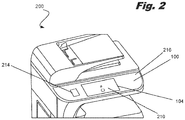
- Fig. 2 is an illustration of an example of a printing device incorporating a modular dashboard, consistent with the disclosed implementations. This example falls outside of the scope of the claims, and is present for illustration purposes only.
- the illustrated printing device includes a user input device (210); at least one pocket (214) adjacent the user input device to accommodate a device for adding functionality to the printing device; a dashboard (100) with a cut-out (104) to surround and accommodate the user input device (210) and a portion to cover the at least one pocket (214); and a receiver (216) for a fastener of the dashboard (100) to removably secure the dashboard (100) to the printing device (200).
- the printing device (200) includes a user input panel (210), which may be a touch-sensitive display device.
- the user input panel (210) is accommodated within the cut-out (104) of, and surrounded completely by, the dashboard (100).
- the printing device (200) lateral to the user input panel (210), the printing device (200) includes the pocket (214). This pocket (214) is shown in ghost in Fig. 2 and is covered by the dashboard (100), when installed.
- the printing device (200) also includes a receiver, shown generically as (216), for the fastener of the dashboard. As indicated above, this receiver (216) may snap to an edge of the dashboard (100) or may be a threaded hole for receiving a thumbscrew of the dashboard (100). Any other example of a removable connection could be used between the printing device (200) and the dashboard (100).
- Fig. 3 is an illustration of an example of a printing device incorporating a modular dashboard according to the invention, consistent with the disclosed implementations.
- the example of Fig. 3 is similar to that of Fig. 2 , except that the dashboard (101) shown in Fig. 3 includes an additional device (300) that is incorporated into the dashboard to add further functionality to the printing device.
- the illustrated printing device (200) includes a user input device (210); at least one pocket (214) adjacent the user input device (210) to accommodate a device for adding functionality to the printing device (200); a removable dashboard (101) with a cut-out (104) to surround and accommodate the user input device (210) and a portion to cover the at least one pocket (214); and an additional device (300) on the dashboard (101) to add further functionality to the printing device (200) with a connection to circuitry of the printing device.
- the dashboard (101) of Fig. 3 can incorporate any number of different additional devices (300) for provide the desired feature set.
- the dashboard (101) may include one or more additional devices (300).
- the additional device (300) may be an additional user input device, such as a keyboard, for example, a capacitive keyboard.
- the additional device (300) may be a security hardware circuit. This security hardware circuit may be perceived as additionally secure for being integrated into the dashboard.
- the security hardware circuit may be, for example, a card reader (both proximity and slide readers), a fingerprint scanner or other biometric scanner, a radio frequency (RF) device (including both Near-Field Communication modules and RF identification (RFID) modules) and others.
- RF radio frequency
- the printing device (200) may include an additional pocket located to the right of the user input device (210), as shown in Fig. 3 , to accommodate the additional device (300). Examples of this configuration will be provided below.
- the dashboard (101) of Fig. 3 also provides for easy upgrade of a basic printing device unit by a distribution center or dealership, or in the field. In any such setting, a more basic dashboard can be swapped out for a dashboard providing the additional functions or features that a user may desire.
- Fig. 4 is an illustration of an example of a printing device with a modular dashboard removed, consistent with the disclosed implementations and further illustrating several of the features discussed above.
- the printing device (200) includes a central user input device (210) which would be surrounded by, and accommodated in, the cut-out of the modular dashboard described above, when that dashboard is installed.
- the printing device (200) On either side of the user input device (210), the printing device (200) includes a pocket (214, 220). Each pocket is simply a compartment in the printing device providing space for installing additional components. When installed, the dashboard described above covers and closes these pockets.
- the pocket (220) may accommodate a security hardware circuit that is either incorporated into the dashboard or simply disposed in the pocket under the dashboard.
- the right pocket (220) contains a Near-Field Communication (NFC) module (406), which is a specific type of RF receiver used to communicate with mobile devices for authentication purposes.
- NFC Near-Field Communication
- the NFC module (406) also includes a Light Emitting Diode (LED) indicator (412).
- LED Light Emitting Diode
- visual signals indicating operation of the NFC module (406) from this indicator (412) may be visible to a user through the dashboard. This would apply similarly to any other visual signaling device on any other component installed in the pockets.
- the pocket (214) may further accommodate any additional devices to augment the printing device. These devices may be either incorporated into the dashboard or simply installed in the pocket (214). Examples, include other security hardware circuits, communication circuits and others.
- PCA printed circuit assembly
- USB Universal Serial Bus
- a cable (410) also connects this PCA (402) with a USB port (408) on the side of the printing device (200).
- This USB port (408) may be used, for example, to connect a USB drive to the printing device (200).
- Such a memory device may contain a document or other print job to be produced in hardcopy form by the printing device or may otherwise be used to transfer data to or from the printing device (200).
- a number of threaded holes (216) are illustrated in Fig. 4 . These holes (416) are used to receive thumbscrews on a dashboard to removably attach the dashboard to the printing device (200) as described above.
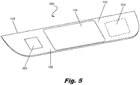
- Fig. 5 is an illustration of another example of a modular dashboard, consistent with the disclosed implementations.
- the dashboard (500) is similar to the dashboard shown in Fig. 1 .
- the dashboard (500) specifically includes a window (504) that is registered with a pocket in the printing device to permit a user to see visual indicators from a component in the pocket, as described above.
- dashboard (500) of Fig. 5 may also include an access door (502). This provides faster access to the pocket on the left without removing the dashboard (500).
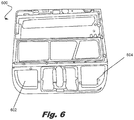
- Fig. 6 is an illustration of an example of a metal frame of a printing device for supporting a modular dashboard, consistent with the disclosed implementations.
- the metal frame (600) includes openings (602, 604) that are registered with the pockets of the printing device described above.
- Fig. 7 is an illustration of the metal frame of Fig. 6 with the dashboard of Fig. 5 installed, consistent with the disclosed implementations.
- the dashboard (500) is installed on the metal frame (600).
- the cut-out (104) of the dashboard (500) provides access to the user input device, described above, which is also supported on the metal frame (600).
- Fig. 8 is an illustration of an example of a printing device incorporating a modular dashboard that is in operation, consistent with the disclosed implementations.
- the printing device (200) includes a dashboard (100), which can be of any of the examples discussed above and other types.
- the cut-out (104) again accommodates the user input device (210).
- the user input device (210) may be supported on a hinged support that allows it to fold from a position flush with the dashboard (100) to an inclined position which is shown in Fig. 8 .
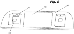
- Fig. 9 is an illustration of an example of a rear side of modular dashboard, consistent with the disclosed implementations.
- the dashboard (500) includes the cut-out (104).
- the dashboard (500) may also include the access door (502) described above.
- the thumbscrews (902) mentioned above is illustrated in Fig. 9 .
Landscapes
- Engineering & Computer Science (AREA)
- Multimedia (AREA)
- Signal Processing (AREA)
- Human Computer Interaction (AREA)
- Accessory Devices And Overall Control Thereof (AREA)
Description
- Printing devices are widely used in personal, business and government settings to produce hardcopy documents from digital data. Many printing devices provide multiple functions such as printing, scanning, copying and others. Because of the different settings where printing devices are used, different features and functions may be desired. For example, in some settings a security device may be incorporated with the printing device to control who can access and operate that printing device. In other setting, a lower level, or security or no such security at all, may be needed. Thus, different purchasers may want printing devices with different features and functions.
-
US2006/226745A1 discloses a base member of an operation panel which is formed with mounting holes, in some of which components are mounted. A plate member overlying the base member is provided with exposing holes aligned with the mounting holes containing components, but has no exposing holes at positions aligned with vacant mounting holes.US6366747B1 discloses a reproduction machine having a control panel which is upgradable by replacement of a portion of the panel with a different user interface panel module.JP2003/298791A US5493365A discloses an image forming apparatus in which an operating section accessible for entering commands is implemented as a plurality of key units which are each removably connected to the body of the operating section via cooperative connectors, so that a defective unit may be replaced while the other units remain in use. - The present invention is set out in the appended set of claims.
- The accompanying drawings illustrate various implementations of the principles described herein and are a part of the specification. The illustrated implementations are merely examples and do not limit the scope of the claims.
-
Fig. 1 is an illustration of an example of a modular dashboard for a printing device, consistent with the disclosed implementations. -
Fig. 2 is an illustration of an example of a printing device incorporating a modular dashboard, consistent with the disclosed implementations. -
Fig. 3 is an illustration of another example of a printing device incorporating a modular dashboard, consistent with the disclosed implementations. -
Fig. 4 is an illustration of an example of a printing device with a modular dashboard removed, consistent with the disclosed implementations. -
Fig. 5 is an illustration of another example of a modular dashboard, consistent with the disclosed implementations. -
Fig. 6 is an illustration of an example of a metal frame of a printing device for supporting a modular dashboard, consistent with the disclosed implementations. -
Fig. 7 is an illustration of the metal frame ofFig. 6 with the dashboard ofFig. 5 installed, consistent with the disclosed implementations. -
Fig. 8 is an illustration of an example of a printing device incorporating a modular dashboard that is in operation, consistent with the disclosed implementations. -
Fig. 9 is an illustration of an example of a rear side of modular dashboard, consistent with the disclosed implementations. - Throughout the drawings, identical reference numbers designate similar, but not necessarily identical, elements.
- As indicated above, printing devices are widely used in personal, business and government settings to produce hardcopy documents from digital data. Because of the different settings where printing devices are used, different features and functions may be desired. Consequently, the present describes a modular dashboard for a printing device that promotes the customization of the printing device to have different features and functions based on the needs of a purchaser.
- In one example, the present specification describes a modular exterior component according to claim 1.
- As used herein and in the following claims, the term "dashboard" refers to an exterior component on or around which user interface elements, such as displays, input device, controls, etc., are arranged.
- As used herein and in the following claims, the term "modular" refers to a self-contained unit, such as a printing device component, that can be readily replaced with a similar unit that may provide different features or functions. In the examples described herein, a printing device dashboard is modular.
- As used herein and in the following claims, the term "removably" refers to a connection or attachment that is not permanent and can be readily undone, for example, by un-snapping a snapped-together joint or unscrewing a thumb screw without needing a tool. Connections or attachments that can be made or unmade by hand, without a tool, are removably made. Connections that can be made or unmade easily with a simple tool are also removably made.
- As used herein in the following claims, term "cut-out" refers to a hole or void in an otherwise continuous sheet of material. A cut-out may be completely surrounded by the material in which it is made or may be in the edge of a sheet of such material.
- As used herein in the following claims, term "security hardware circuit" refers to a hardware device for providing a security feature to a printing device, controlling use of the printing device. For example, a security hardware circuit may include a card reader (both proximity and slide readers), a fingerprint scanner or other biometric scanner, a radio frequency (RF) device (including both Near-Field Communication modules and RF identification (RFID) modules) and others.
-
Fig. 1 is an illustration of an example of a modular dashboard for a printing device, consistent with the disclosed implementations. This example falls outside of the scope of the claims, and is present for illustration purposes only. As shown inFig. 1 , the dashboard (100) includes a board (102); a cut-out (104) in the board (102) to accommodate user controls on the printing device; a lateral portion (106) of the board (102) that is lateral to the cut-out (104) to cover a pocket in the printing device for containing a device adding functionality to the printing device; and a fastener (108) for removably attaching the board to the printing device. - In some examples, the board (102) is a sheet of transparent material, such as glass or plastic, adhered to a sheet metal layer. The transparent material may be tinted so as to be only partially transparent. As will be described in further detail below, the sheet metal layer may include windows such that the transparency of the transparent material allows the user to see indicators or components placed below the board.
- The cut-out (104) provides access through the dashboard (100) to user controls already on the printing device, such as a touch sensitive display. In the illustrated example, the cut-out (104) completely surrounds the user controls. This will be demonstrated further below.
- The fastener (108) is generically illustrated in
Fig. 1 . As indicated this fastener (108) is to removeably attach the dashboard (100) to a supporting printing device. The fastener (108) may be an edge of the board (102) that is snapped into a corresponding receiver of the printing device. In other examples, the fastener (108) may be a thumbscrew that is screwed by hand into a threaded hole of the printing device. -
Fig. 2 is an illustration of an example of a printing device incorporating a modular dashboard, consistent with the disclosed implementations. This example falls outside of the scope of the claims, and is present for illustration purposes only. The illustrated printing device includes a user input device (210); at least one pocket (214) adjacent the user input device to accommodate a device for adding functionality to the printing device; a dashboard (100) with a cut-out (104) to surround and accommodate the user input device (210) and a portion to cover the at least one pocket (214); and a receiver (216) for a fastener of the dashboard (100) to removably secure the dashboard (100) to the printing device (200). - As shown in
Fig. 2 , the printing device (200) includes a user input panel (210), which may be a touch-sensitive display device. The user input panel (210) is accommodated within the cut-out (104) of, and surrounded completely by, the dashboard (100). - Lateral to the user input panel (210), the printing device (200) includes the pocket (214). This pocket (214) is shown in ghost in
Fig. 2 and is covered by the dashboard (100), when installed. - The printing device (200) also includes a receiver, shown generically as (216), for the fastener of the dashboard. As indicated above, this receiver (216) may snap to an edge of the dashboard (100) or may be a threaded hole for receiving a thumbscrew of the dashboard (100). Any other example of a removable connection could be used between the printing device (200) and the dashboard (100).
-
Fig. 3 is an illustration of an example of a printing device incorporating a modular dashboard according to the invention, consistent with the disclosed implementations. The example ofFig. 3 is similar to that ofFig. 2 , except that the dashboard (101) shown inFig. 3 includes an additional device (300) that is incorporated into the dashboard to add further functionality to the printing device. - In
Fig. 3 , the illustrated printing device (200) includes a user input device (210); at least one pocket (214) adjacent the user input device (210) to accommodate a device for adding functionality to the printing device (200); a removable dashboard (101) with a cut-out (104) to surround and accommodate the user input device (210) and a portion to cover the at least one pocket (214); and an additional device (300) on the dashboard (101) to add further functionality to the printing device (200) with a connection to circuitry of the printing device. - Users that desire a basic printing device may prefer the modular dashboard (100) of
Fig. 2 . However, for users that desire additional features or functionality, the dashboard (101) ofFig. 3 can incorporate any number of different additional devices (300) for provide the desired feature set. The dashboard (101) may include one or more additional devices (300). - For example, the additional device (300) may be an additional user input device, such as a keyboard, for example, a capacitive keyboard. In other examples, the additional device (300) may be a security hardware circuit. This security hardware circuit may be perceived as additionally secure for being integrated into the dashboard. The security hardware circuit may be, for example, a card reader (both proximity and slide readers), a fingerprint scanner or other biometric scanner, a radio frequency (RF) device (including both Near-Field Communication modules and RF identification (RFID) modules) and others.
- If the additional device (300) needs the space, the printing device (200) may include an additional pocket located to the right of the user input device (210), as shown in
Fig. 3 , to accommodate the additional device (300). Examples of this configuration will be provided below. - The dashboard (101) of
Fig. 3 also provides for easy upgrade of a basic printing device unit by a distribution center or dealership, or in the field. In any such setting, a more basic dashboard can be swapped out for a dashboard providing the additional functions or features that a user may desire. -
Fig. 4 is an illustration of an example of a printing device with a modular dashboard removed, consistent with the disclosed implementations and further illustrating several of the features discussed above. As shown inFig. 4 , the printing device (200) includes a central user input device (210) which would be surrounded by, and accommodated in, the cut-out of the modular dashboard described above, when that dashboard is installed. - On either side of the user input device (210), the printing device (200) includes a pocket (214, 220). Each pocket is simply a compartment in the printing device providing space for installing additional components. When installed, the dashboard described above covers and closes these pockets.
- On the right, the pocket (220) may accommodate a security hardware circuit that is either incorporated into the dashboard or simply disposed in the pocket under the dashboard. In the illustrated example, the right pocket (220) contains a Near-Field Communication (NFC) module (406), which is a specific type of RF receiver used to communicate with mobile devices for authentication purposes. The NFC module (406) also includes a Light Emitting Diode (LED) indicator (412). As noted above, visual signals indicating operation of the NFC module (406) from this indicator (412) may be visible to a user through the dashboard. This would apply similarly to any other visual signaling device on any other component installed in the pockets.
- On the left, the pocket (214) may further accommodate any additional devices to augment the printing device. These devices may be either incorporated into the dashboard or simply installed in the pocket (214). Examples, include other security hardware circuits, communication circuits and others.
- Visible in the left pocket (214) is a printed circuit assembly (PCA) (402) that is part of the electronics of the printing device (200). In the illustrated example, the PCA (402) includes a number of Universal Serial Bus (USB) connectors (404) that may be used to connect components in either of the pockets (214, 220) to the PCA and the internal electronics of the printing device.
- A cable (410) also connects this PCA (402) with a USB port (408) on the side of the printing device (200). This USB port (408) may be used, for example, to connect a USB drive to the printing device (200). Such a memory device may contain a document or other print job to be produced in hardcopy form by the printing device or may otherwise be used to transfer data to or from the printing device (200).
- Lastly, a number of threaded holes (216) are illustrated in
Fig. 4 . These holes (416) are used to receive thumbscrews on a dashboard to removably attach the dashboard to the printing device (200) as described above. -
Fig. 5 is an illustration of another example of a modular dashboard, consistent with the disclosed implementations. As shown inFig. 4 , the dashboard (500) is similar to the dashboard shown inFig. 1 . However, the dashboard (500) specifically includes a window (504) that is registered with a pocket in the printing device to permit a user to see visual indicators from a component in the pocket, as described above. - Some examples of the dashboard (500) of
Fig. 5 may also include an access door (502). This provides faster access to the pocket on the left without removing the dashboard (500). -
Fig. 6 is an illustration of an example of a metal frame of a printing device for supporting a modular dashboard, consistent with the disclosed implementations. As shown inFig. 6 , the metal frame (600) includes openings (602, 604) that are registered with the pockets of the printing device described above. -
Fig. 7 is an illustration of the metal frame ofFig. 6 with the dashboard ofFig. 5 installed, consistent with the disclosed implementations. As shown inFig. 7 , the dashboard (500) is installed on the metal frame (600). The cut-out (104) of the dashboard (500) provides access to the user input device, described above, which is also supported on the metal frame (600). -
Fig. 8 is an illustration of an example of a printing device incorporating a modular dashboard that is in operation, consistent with the disclosed implementations. As shown inFig. 8 , the printing device (200) includes a dashboard (100), which can be of any of the examples discussed above and other types. - The cut-out (104) again accommodates the user input device (210). As shown in
Fig. 8 , the user input device (210) may be supported on a hinged support that allows it to fold from a position flush with the dashboard (100) to an inclined position which is shown inFig. 8 . -
Fig. 9 is an illustration of an example of a rear side of modular dashboard, consistent with the disclosed implementations. As shown inFig. 9 , the dashboard (500) includes the cut-out (104). The dashboard (500) may also include the access door (502) described above. Lastly, one example of the thumbscrews (902) mentioned above is illustrated inFig. 9 . - The preceding description has been presented only to illustrate and describe examples of the principles described. This description is not intended to be exhaustive or to limit these principles to any precise form disclosed. Many modifications and variations are possible in light of the above teaching.
Claims (11)
- A modular exterior component (100; 500) for a printing device (200), the exterior component (100; 500) comprising:a board (102);a cut-out (104) in the board (102) to accommodate user controls (210) on the printing device (200);a lateral portion (106) of the board (102) that is lateral to the cut-out (104) to cover a pocket (214; 220) in the printing device (200) to contain a device adding functionality to the printing device (200); anda fastener (108) to removably attach the board (102) to the printing device (200); characterised in that the exterior component further comprisesat least one of (i) an additional user input device (300) incorporated into the board (102) with a connector to connect to circuitry of the printing device (200), or (ii) a security hardware circuit (300) incorporated into the board (102) with a connector for connecting to circuitry of the printing device.
- The modular exterior component of claim 1, wherein the board (102) comprises a layer of transparent material on a sheet metal frame (600).
- The modular exterior component of claim 2 further comprising a window (504) in the sheet metal frame covered by the transparent material to align with the pocket (214; 220) in the printing device (200).
- The modular exterior component of any one of claims 1 to 3, wherein the board (102) comprises two lateral portions (106) on either side of the cut-out (104), each lateral portion (106) to cover a pocket (214; 220) in the printing device (200) for containing a device adding functionality to the printing device (200).
- The modular exterior component of any preceding claim, wherein the additional user input device (300) comprises a keyboard.
- The modular exterior component of any preceding claim, wherein the security hardware circuit (300) comprises a card reader.
- The modular exterior component of any preceding claim, wherein the fastener (108) comprises at least one thumb screw.
- A printing device (200) comprising:the modular exterior component (100; 500) of any preceding claim;a user input device (210);at least one pocket (214; 220) adjacent the user input device (210) to accommodate a device to add functionality to the printing device (200);the cut-out (104) of the modular exterior component (100; 500) surrounding and accommodating the user input device (210), and the lateral portion (106) of the modular exterior component (100; 500) covering the at least one pocket (214; 220); anda receiver (216) for the fastener (108) of the modular exterior component (100; 500) to removably secure the modular exterior component (100; 500) to the printing device (200).
- The printing device of claim 8, further comprising a printed circuit assembly (402) - PCA - of the printing device (200) comprising at least one Universal Serial Bus (404) - USB - port accessible from inside the at least one pocket (214; 220) to accommodate a device for adding functionality to the printing device (200) in the pocket (214; 220).
- The printing device of claim 8 or 9, further comprising a security hardware device (406) for authenticating users of the printing device (200) disposed in the at least one pocket (214; 220) of the printing device (200).
- The printing device of claim 8, 9 or 10, wherein the user input device (210) is a touch sensitive screen.
Applications Claiming Priority (1)
| Application Number | Priority Date | Filing Date | Title |
|---|---|---|---|
| PCT/US2016/040693 WO2018004657A1 (en) | 2016-07-01 | 2016-07-01 | Printing device dashboard |
Publications (3)
| Publication Number | Publication Date |
|---|---|
| EP3436282A1 EP3436282A1 (en) | 2019-02-06 |
| EP3436282A4 EP3436282A4 (en) | 2019-11-20 |
| EP3436282B1 true EP3436282B1 (en) | 2021-01-20 |
Family
ID=60786516
Family Applications (1)
| Application Number | Title | Priority Date | Filing Date |
|---|---|---|---|
| EP16907607.2A Not-in-force EP3436282B1 (en) | 2016-07-01 | 2016-07-01 | Printing device dashboard |
Country Status (4)
| Country | Link |
|---|---|
| US (1) | US10666823B2 (en) |
| EP (1) | EP3436282B1 (en) |
| CN (1) | CN109153273A (en) |
| WO (1) | WO2018004657A1 (en) |
Families Citing this family (3)
| Publication number | Priority date | Publication date | Assignee | Title |
|---|---|---|---|---|
| JP7238478B2 (en) * | 2019-03-04 | 2023-03-14 | ブラザー工業株式会社 | image forming device |
| JP7001140B1 (en) * | 2020-12-08 | 2022-01-19 | セイコーエプソン株式会社 | Processing equipment and recording equipment |
| JP7615764B2 (en) * | 2021-02-26 | 2025-01-17 | セイコーエプソン株式会社 | Printing device |
Family Cites Families (19)
| Publication number | Priority date | Publication date | Assignee | Title |
|---|---|---|---|---|
| JPS51142561A (en) | 1975-06-02 | 1976-12-08 | Iwatani & Co | Method of rapidlyyfreezing pork carcass |
| US5657066A (en) * | 1992-10-02 | 1997-08-12 | Zebra Technologies Corporation | Thermal demand printer |
| US5283862A (en) * | 1989-10-11 | 1994-02-01 | Lund Alan K | Notebook computer with reversible cover for external use of membrane switch screen |
| JP3467061B2 (en) * | 1993-06-25 | 2003-11-17 | 株式会社リコー | Operation unit and image forming apparatus |
| JPH07304237A (en) | 1994-05-11 | 1995-11-21 | Tec Corp | Printer |
| JPH07334287A (en) * | 1994-06-02 | 1995-12-22 | Brother Ind Ltd | Small electronic device |
| US6366747B1 (en) * | 1999-06-24 | 2002-04-02 | Xerox Corporation | Customizable control panel for a functionally upgradable image printing machine |
| JP3832370B2 (en) * | 2002-03-29 | 2006-10-11 | 村田機械株式会社 | Mask cover for operation panel and communication terminal device having the same |
| JP2006295885A (en) * | 2005-03-14 | 2006-10-26 | Seiko Epson Corp | Operation panel, manufacturing method thereof, and electronic control device |
| GB0611581D0 (en) | 2006-06-12 | 2006-07-19 | Dymo Nv | Label printer |
| JP4744396B2 (en) * | 2006-08-22 | 2011-08-10 | コニカミノルタビジネステクノロジーズ株式会社 | Image forming apparatus and method for controlling image forming apparatus |
| JP4433030B2 (en) * | 2007-10-01 | 2010-03-17 | ブラザー工業株式会社 | Image processing apparatus and control program for image processing apparatus |
| JP5238104B2 (en) | 2007-12-28 | 2013-07-17 | 株式会社相模化学金属 | Traveling device using permanent magnets |
| JP5621403B2 (en) | 2010-08-18 | 2014-11-12 | 富士ゼロックス株式会社 | Image processing apparatus and image forming apparatus |
| US20130083338A1 (en) | 2011-09-30 | 2013-04-04 | Mark A. Fahrenkrug | Printing system with deep suspend mode |
| ES2598826T3 (en) | 2013-01-24 | 2017-01-30 | Avery Dennison Corporation | Printer |
| JP6240006B2 (en) * | 2013-06-05 | 2017-11-29 | シャープ株式会社 | Image forming apparatus |
| EP3150394B1 (en) | 2014-05-29 | 2019-08-28 | Kyocera Document Solutions Inc. | Image formation device |
| US20170019546A1 (en) * | 2015-07-13 | 2017-01-19 | Xerox Corporation | Method and system to provide an accessibility user interface |
-
2016
- 2016-07-01 US US16/093,427 patent/US10666823B2/en not_active Expired - Fee Related
- 2016-07-01 CN CN201680085214.0A patent/CN109153273A/en active Pending
- 2016-07-01 EP EP16907607.2A patent/EP3436282B1/en not_active Not-in-force
- 2016-07-01 WO PCT/US2016/040693 patent/WO2018004657A1/en not_active Ceased
Non-Patent Citations (1)
| Title |
|---|
| None * |
Also Published As
| Publication number | Publication date |
|---|---|
| US20190124221A1 (en) | 2019-04-25 |
| EP3436282A4 (en) | 2019-11-20 |
| WO2018004657A1 (en) | 2018-01-04 |
| US10666823B2 (en) | 2020-05-26 |
| CN109153273A (en) | 2019-01-04 |
| EP3436282A1 (en) | 2019-02-06 |
Similar Documents
| Publication | Publication Date | Title |
|---|---|---|
| US9600085B1 (en) | Modular modifiable computer keyboard | |
| EP1879363B1 (en) | Mobile terminal | |
| EP2591412B1 (en) | A cover for an electronic device | |
| US8988696B2 (en) | Image forming apparatus | |
| US8736862B2 (en) | Operating section structure, image processing apparatus, and information processing apparatus | |
| EP3436282B1 (en) | Printing device dashboard | |
| US7239509B1 (en) | Modular computer components | |
| CN100533995C (en) | SIM/UIM card arrangement | |
| WO2019223050A1 (en) | Rearview mirror and method for preventing tampering of etc module in rearview mirror | |
| US20050264539A1 (en) | Electronic apparatus | |
| US20170011385A1 (en) | Active peripheral device and electronic payment terminal | |
| EP2899607B1 (en) | Display device for a vehicle | |
| EP3437889B1 (en) | Operation panel and image forming apparatus including this | |
| EP1434410A1 (en) | Telephone set attaching member and portable telephone set | |
| JPH1039945A (en) | Computer system and expansion unit applied to the system | |
| US20030198010A1 (en) | Portable computer system with external bay to create rugged interface with electronic device modules | |
| CN218213946U (en) | Card reading and writing integrated machine | |
| CN214670911U (en) | Automatic face identification self-service equipment of business of shooing goes up and down | |
| KR200443006Y1 (en) | Taxi meter | |
| CN212365123U (en) | Double-screen display multifunctional POS machine | |
| US20160110967A1 (en) | Self-service financial transaction terminal | |
| KR200179207Y1 (en) | Manless information terminal | |
| CN210052213U (en) | Visitor machine | |
| CN119865554A (en) | Correction device | |
| JPH08185268A (en) | Input device |
Legal Events
| Date | Code | Title | Description |
|---|---|---|---|
| STAA | Information on the status of an ep patent application or granted ep patent |
Free format text: STATUS: THE INTERNATIONAL PUBLICATION HAS BEEN MADE |
|
| PUAI | Public reference made under article 153(3) epc to a published international application that has entered the european phase |
Free format text: ORIGINAL CODE: 0009012 |
|
| STAA | Information on the status of an ep patent application or granted ep patent |
Free format text: STATUS: REQUEST FOR EXAMINATION WAS MADE |
|
| 17P | Request for examination filed |
Effective date: 20181015 |
|
| AK | Designated contracting states |
Kind code of ref document: A1 Designated state(s): AL AT BE BG CH CY CZ DE DK EE ES FI FR GB GR HR HU IE IS IT LI LT LU LV MC MK MT NL NO PL PT RO RS SE SI SK SM TR |
|
| AX | Request for extension of the european patent |
Extension state: BA ME |
|
| RAP1 | Party data changed (applicant data changed or rights of an application transferred) |
Owner name: HEWLETT-PACKARD DEVELOPMENT COMPANY, L.P. |
|
| DAV | Request for validation of the european patent (deleted) | ||
| DAX | Request for extension of the european patent (deleted) | ||
| A4 | Supplementary search report drawn up and despatched |
Effective date: 20191021 |
|
| RIC1 | Information provided on ipc code assigned before grant |
Ipc: H04N 1/00 20060101ALI20191015BHEP Ipc: B41J 29/00 20060101AFI20191015BHEP |
|
| GRAP | Despatch of communication of intention to grant a patent |
Free format text: ORIGINAL CODE: EPIDOSNIGR1 |
|
| STAA | Information on the status of an ep patent application or granted ep patent |
Free format text: STATUS: GRANT OF PATENT IS INTENDED |
|
| INTG | Intention to grant announced |
Effective date: 20201007 |
|
| GRAS | Grant fee paid |
Free format text: ORIGINAL CODE: EPIDOSNIGR3 |
|
| GRAA | (expected) grant |
Free format text: ORIGINAL CODE: 0009210 |
|
| STAA | Information on the status of an ep patent application or granted ep patent |
Free format text: STATUS: THE PATENT HAS BEEN GRANTED |
|
| AK | Designated contracting states |
Kind code of ref document: B1 Designated state(s): AL AT BE BG CH CY CZ DE DK EE ES FI FR GB GR HR HU IE IS IT LI LT LU LV MC MK MT NL NO PL PT RO RS SE SI SK SM TR |
|
| REG | Reference to a national code |
Ref country code: GB Ref legal event code: FG4D |
|
| REG | Reference to a national code |
Ref country code: CH Ref legal event code: EP |
|
| REG | Reference to a national code |
Ref country code: DE Ref legal event code: R096 Ref document number: 602016051914 Country of ref document: DE |
|
| REG | Reference to a national code |
Ref country code: AT Ref legal event code: REF Ref document number: 1356054 Country of ref document: AT Kind code of ref document: T Effective date: 20210215 |
|
| REG | Reference to a national code |
Ref country code: IE Ref legal event code: FG4D |
|
| REG | Reference to a national code |
Ref country code: NL Ref legal event code: MP Effective date: 20210120 |
|
| REG | Reference to a national code |
Ref country code: LT Ref legal event code: MG9D |
|
| REG | Reference to a national code |
Ref country code: AT Ref legal event code: MK05 Ref document number: 1356054 Country of ref document: AT Kind code of ref document: T Effective date: 20210120 |
|
| PG25 | Lapsed in a contracting state [announced via postgrant information from national office to epo] |
Ref country code: LT Free format text: LAPSE BECAUSE OF FAILURE TO SUBMIT A TRANSLATION OF THE DESCRIPTION OR TO PAY THE FEE WITHIN THE PRESCRIBED TIME-LIMIT Effective date: 20210120 Ref country code: BG Free format text: LAPSE BECAUSE OF FAILURE TO SUBMIT A TRANSLATION OF THE DESCRIPTION OR TO PAY THE FEE WITHIN THE PRESCRIBED TIME-LIMIT Effective date: 20210420 Ref country code: NO Free format text: LAPSE BECAUSE OF FAILURE TO SUBMIT A TRANSLATION OF THE DESCRIPTION OR TO PAY THE FEE WITHIN THE PRESCRIBED TIME-LIMIT Effective date: 20210420 Ref country code: PT Free format text: LAPSE BECAUSE OF FAILURE TO SUBMIT A TRANSLATION OF THE DESCRIPTION OR TO PAY THE FEE WITHIN THE PRESCRIBED TIME-LIMIT Effective date: 20210520 Ref country code: GR Free format text: LAPSE BECAUSE OF FAILURE TO SUBMIT A TRANSLATION OF THE DESCRIPTION OR TO PAY THE FEE WITHIN THE PRESCRIBED TIME-LIMIT Effective date: 20210421 Ref country code: FI Free format text: LAPSE BECAUSE OF FAILURE TO SUBMIT A TRANSLATION OF THE DESCRIPTION OR TO PAY THE FEE WITHIN THE PRESCRIBED TIME-LIMIT Effective date: 20210120 Ref country code: HR Free format text: LAPSE BECAUSE OF FAILURE TO SUBMIT A TRANSLATION OF THE DESCRIPTION OR TO PAY THE FEE WITHIN THE PRESCRIBED TIME-LIMIT Effective date: 20210120 |
|
| PG25 | Lapsed in a contracting state [announced via postgrant information from national office to epo] |
Ref country code: SE Free format text: LAPSE BECAUSE OF FAILURE TO SUBMIT A TRANSLATION OF THE DESCRIPTION OR TO PAY THE FEE WITHIN THE PRESCRIBED TIME-LIMIT Effective date: 20210120 Ref country code: AT Free format text: LAPSE BECAUSE OF FAILURE TO SUBMIT A TRANSLATION OF THE DESCRIPTION OR TO PAY THE FEE WITHIN THE PRESCRIBED TIME-LIMIT Effective date: 20210120 Ref country code: PL Free format text: LAPSE BECAUSE OF FAILURE TO SUBMIT A TRANSLATION OF THE DESCRIPTION OR TO PAY THE FEE WITHIN THE PRESCRIBED TIME-LIMIT Effective date: 20210120 Ref country code: LV Free format text: LAPSE BECAUSE OF FAILURE TO SUBMIT A TRANSLATION OF THE DESCRIPTION OR TO PAY THE FEE WITHIN THE PRESCRIBED TIME-LIMIT Effective date: 20210120 Ref country code: RS Free format text: LAPSE BECAUSE OF FAILURE TO SUBMIT A TRANSLATION OF THE DESCRIPTION OR TO PAY THE FEE WITHIN THE PRESCRIBED TIME-LIMIT Effective date: 20210120 |
|
| PG25 | Lapsed in a contracting state [announced via postgrant information from national office to epo] |
Ref country code: IS Free format text: LAPSE BECAUSE OF FAILURE TO SUBMIT A TRANSLATION OF THE DESCRIPTION OR TO PAY THE FEE WITHIN THE PRESCRIBED TIME-LIMIT Effective date: 20210520 |
|
| REG | Reference to a national code |
Ref country code: DE Ref legal event code: R097 Ref document number: 602016051914 Country of ref document: DE |
|
| PG25 | Lapsed in a contracting state [announced via postgrant information from national office to epo] |
Ref country code: SM Free format text: LAPSE BECAUSE OF FAILURE TO SUBMIT A TRANSLATION OF THE DESCRIPTION OR TO PAY THE FEE WITHIN THE PRESCRIBED TIME-LIMIT Effective date: 20210120 Ref country code: CZ Free format text: LAPSE BECAUSE OF FAILURE TO SUBMIT A TRANSLATION OF THE DESCRIPTION OR TO PAY THE FEE WITHIN THE PRESCRIBED TIME-LIMIT Effective date: 20210120 Ref country code: EE Free format text: LAPSE BECAUSE OF FAILURE TO SUBMIT A TRANSLATION OF THE DESCRIPTION OR TO PAY THE FEE WITHIN THE PRESCRIBED TIME-LIMIT Effective date: 20210120 |
|
| PLBE | No opposition filed within time limit |
Free format text: ORIGINAL CODE: 0009261 |
|
| STAA | Information on the status of an ep patent application or granted ep patent |
Free format text: STATUS: NO OPPOSITION FILED WITHIN TIME LIMIT |
|
| PG25 | Lapsed in a contracting state [announced via postgrant information from national office to epo] |
Ref country code: DK Free format text: LAPSE BECAUSE OF FAILURE TO SUBMIT A TRANSLATION OF THE DESCRIPTION OR TO PAY THE FEE WITHIN THE PRESCRIBED TIME-LIMIT Effective date: 20210120 Ref country code: RO Free format text: LAPSE BECAUSE OF FAILURE TO SUBMIT A TRANSLATION OF THE DESCRIPTION OR TO PAY THE FEE WITHIN THE PRESCRIBED TIME-LIMIT Effective date: 20210120 Ref country code: SK Free format text: LAPSE BECAUSE OF FAILURE TO SUBMIT A TRANSLATION OF THE DESCRIPTION OR TO PAY THE FEE WITHIN THE PRESCRIBED TIME-LIMIT Effective date: 20210120 |
|
| 26N | No opposition filed |
Effective date: 20211021 |
|
| PG25 | Lapsed in a contracting state [announced via postgrant information from national office to epo] |
Ref country code: AL Free format text: LAPSE BECAUSE OF FAILURE TO SUBMIT A TRANSLATION OF THE DESCRIPTION OR TO PAY THE FEE WITHIN THE PRESCRIBED TIME-LIMIT Effective date: 20210120 Ref country code: ES Free format text: LAPSE BECAUSE OF FAILURE TO SUBMIT A TRANSLATION OF THE DESCRIPTION OR TO PAY THE FEE WITHIN THE PRESCRIBED TIME-LIMIT Effective date: 20210120 |
|
| PG25 | Lapsed in a contracting state [announced via postgrant information from national office to epo] |
Ref country code: SI Free format text: LAPSE BECAUSE OF FAILURE TO SUBMIT A TRANSLATION OF THE DESCRIPTION OR TO PAY THE FEE WITHIN THE PRESCRIBED TIME-LIMIT Effective date: 20210120 |
|
| REG | Reference to a national code |
Ref country code: CH Ref legal event code: PL |
|
| PG25 | Lapsed in a contracting state [announced via postgrant information from national office to epo] |
Ref country code: MC Free format text: LAPSE BECAUSE OF FAILURE TO SUBMIT A TRANSLATION OF THE DESCRIPTION OR TO PAY THE FEE WITHIN THE PRESCRIBED TIME-LIMIT Effective date: 20210120 |
|
| REG | Reference to a national code |
Ref country code: BE Ref legal event code: MM Effective date: 20210731 |
|
| PG25 | Lapsed in a contracting state [announced via postgrant information from national office to epo] |
Ref country code: LI Free format text: LAPSE BECAUSE OF NON-PAYMENT OF DUE FEES Effective date: 20210731 Ref country code: IT Free format text: LAPSE BECAUSE OF FAILURE TO SUBMIT A TRANSLATION OF THE DESCRIPTION OR TO PAY THE FEE WITHIN THE PRESCRIBED TIME-LIMIT Effective date: 20210120 Ref country code: CH Free format text: LAPSE BECAUSE OF NON-PAYMENT OF DUE FEES Effective date: 20210731 |
|
| PG25 | Lapsed in a contracting state [announced via postgrant information from national office to epo] |
Ref country code: IS Free format text: LAPSE BECAUSE OF FAILURE TO SUBMIT A TRANSLATION OF THE DESCRIPTION OR TO PAY THE FEE WITHIN THE PRESCRIBED TIME-LIMIT Effective date: 20210520 Ref country code: LU Free format text: LAPSE BECAUSE OF NON-PAYMENT OF DUE FEES Effective date: 20210701 |
|
| PG25 | Lapsed in a contracting state [announced via postgrant information from national office to epo] |
Ref country code: IE Free format text: LAPSE BECAUSE OF NON-PAYMENT OF DUE FEES Effective date: 20210701 Ref country code: BE Free format text: LAPSE BECAUSE OF NON-PAYMENT OF DUE FEES Effective date: 20210731 |
|
| PGFP | Annual fee paid to national office [announced via postgrant information from national office to epo] |
Ref country code: GB Payment date: 20220621 Year of fee payment: 7 |
|
| PGFP | Annual fee paid to national office [announced via postgrant information from national office to epo] |
Ref country code: FR Payment date: 20220621 Year of fee payment: 7 |
|
| PGFP | Annual fee paid to national office [announced via postgrant information from national office to epo] |
Ref country code: DE Payment date: 20220621 Year of fee payment: 7 |
|
| PG25 | Lapsed in a contracting state [announced via postgrant information from national office to epo] |
Ref country code: NL Free format text: LAPSE BECAUSE OF NON-PAYMENT OF DUE FEES Effective date: 20210120 Ref country code: CY Free format text: LAPSE BECAUSE OF FAILURE TO SUBMIT A TRANSLATION OF THE DESCRIPTION OR TO PAY THE FEE WITHIN THE PRESCRIBED TIME-LIMIT Effective date: 20210120 |
|
| PG25 | Lapsed in a contracting state [announced via postgrant information from national office to epo] |
Ref country code: HU Free format text: LAPSE BECAUSE OF FAILURE TO SUBMIT A TRANSLATION OF THE DESCRIPTION OR TO PAY THE FEE WITHIN THE PRESCRIBED TIME-LIMIT; INVALID AB INITIO Effective date: 20160701 |
|
| REG | Reference to a national code |
Ref country code: DE Ref legal event code: R119 Ref document number: 602016051914 Country of ref document: DE |
|
| GBPC | Gb: european patent ceased through non-payment of renewal fee |
Effective date: 20230701 |
|
| PG25 | Lapsed in a contracting state [announced via postgrant information from national office to epo] |
Ref country code: MK Free format text: LAPSE BECAUSE OF FAILURE TO SUBMIT A TRANSLATION OF THE DESCRIPTION OR TO PAY THE FEE WITHIN THE PRESCRIBED TIME-LIMIT Effective date: 20210120 Ref country code: DE Free format text: LAPSE BECAUSE OF NON-PAYMENT OF DUE FEES Effective date: 20240201 Ref country code: GB Free format text: LAPSE BECAUSE OF NON-PAYMENT OF DUE FEES Effective date: 20230701 |
|
| PG25 | Lapsed in a contracting state [announced via postgrant information from national office to epo] |
Ref country code: FR Free format text: LAPSE BECAUSE OF NON-PAYMENT OF DUE FEES Effective date: 20230731 |
|
| PG25 | Lapsed in a contracting state [announced via postgrant information from national office to epo] |
Ref country code: TR Free format text: LAPSE BECAUSE OF FAILURE TO SUBMIT A TRANSLATION OF THE DESCRIPTION OR TO PAY THE FEE WITHIN THE PRESCRIBED TIME-LIMIT Effective date: 20210120 |
|
| PG25 | Lapsed in a contracting state [announced via postgrant information from national office to epo] |
Ref country code: MT Free format text: LAPSE BECAUSE OF FAILURE TO SUBMIT A TRANSLATION OF THE DESCRIPTION OR TO PAY THE FEE WITHIN THE PRESCRIBED TIME-LIMIT Effective date: 20210120 |