JP6201372B2 - Recording device - Google Patents
Recording device Download PDFInfo
- Publication number
- JP6201372B2 JP6201372B2 JP2013071635A JP2013071635A JP6201372B2 JP 6201372 B2 JP6201372 B2 JP 6201372B2 JP 2013071635 A JP2013071635 A JP 2013071635A JP 2013071635 A JP2013071635 A JP 2013071635A JP 6201372 B2 JP6201372 B2 JP 6201372B2
- Authority
- JP
- Japan
- Prior art keywords
- battery
- medium
- main body
- apparatus main
- recording
- Prior art date
- Legal status (The legal status is an assumption and is not a legal conclusion. Google has not performed a legal analysis and makes no representation as to the accuracy of the status listed.)
- Active
Links
Images


Classifications
-
- B—PERFORMING OPERATIONS; TRANSPORTING
- B41—PRINTING; LINING MACHINES; TYPEWRITERS; STAMPS
- B41J—TYPEWRITERS; SELECTIVE PRINTING MECHANISMS, i.e. MECHANISMS PRINTING OTHERWISE THAN FROM A FORME; CORRECTION OF TYPOGRAPHICAL ERRORS
- B41J23/00—Power drives for actions or mechanisms
-
- B—PERFORMING OPERATIONS; TRANSPORTING
- B41—PRINTING; LINING MACHINES; TYPEWRITERS; STAMPS
- B41J—TYPEWRITERS; SELECTIVE PRINTING MECHANISMS, i.e. MECHANISMS PRINTING OTHERWISE THAN FROM A FORME; CORRECTION OF TYPOGRAPHICAL ERRORS
- B41J29/00—Details of, or accessories for, typewriters or selective printing mechanisms not otherwise provided for
- B41J29/02—Framework
- B41J29/023—Framework with reduced dimensions
-
- B—PERFORMING OPERATIONS; TRANSPORTING
- B41—PRINTING; LINING MACHINES; TYPEWRITERS; STAMPS
- B41J—TYPEWRITERS; SELECTIVE PRINTING MECHANISMS, i.e. MECHANISMS PRINTING OTHERWISE THAN FROM A FORME; CORRECTION OF TYPOGRAPHICAL ERRORS
- B41J29/00—Details of, or accessories for, typewriters or selective printing mechanisms not otherwise provided for
- B41J29/38—Drives, motors, controls or automatic cut-off devices for the entire printing mechanism
- B41J29/393—Devices for controlling or analysing the entire machine ; Controlling or analysing mechanical parameters involving printing of test patterns
Landscapes
- Accessory Devices And Overall Control Thereof (AREA)
- Printers Characterized By Their Purpose (AREA)
- Ink Jet (AREA)
Description
本発明は、ファクシミリやプリンター等に代表される記録装置に関する。 The present invention relates to a recording apparatus represented by a facsimile, a printer, and the like.
デジタルカメラやノート型パーソナルコンピューター等の携帯性を備えた電子機器には、機器本体に対してバッテリーが着脱自在に取り付けられる。ファクリミリやプリンター等に代表される記録装置においても、バッテリーを有し、且つ小型・軽量で、携帯性を備えたものが出回っている。特許文献1及び2に示すプリンターは、その一例である。 A battery is detachably attached to the main body of a portable electronic device such as a digital camera or a notebook personal computer. Recording apparatuses typified by facri millimeters and printers have a battery, are small and light, and are portable. The printers shown in Patent Documents 1 and 2 are examples.
特許文献1、2に記載のプリンターはいずれも、バッテリー取付面が機器背面の全体に渡って設定されており、即ちバッテリーの着脱操作を機器背面側から行うことを前提として設計されている。従ってバッテリーの着脱作業時には、ユーザーはバッテリー取付面を視認する為にプリンター背面が手前を向くように、設置の向きを変える必要がある。即ち、印刷時の機器の向きとバッテリー着脱作業時の機器の向きが異なる為、必ずしも操作性が良好とは言えなかった。 Each of the printers described in Patent Documents 1 and 2 is designed on the assumption that the battery mounting surface is set over the entire back of the device, that is, the battery is attached and detached from the back of the device. Therefore, when attaching and detaching the battery, the user needs to change the installation direction so that the back of the printer faces forward in order to visually recognize the battery mounting surface. That is, since the orientation of the device during printing and the orientation of the device during battery attachment / detachment work are different, it cannot be said that the operability is necessarily good.
加えて、特許文献1、2記載のプリンターのいずれも、バッテリー装着によって当該バッテリーを含めた装置全体の容積が機器背面側に増大する。このため、携帯性を備えた機器として携帯性に劣るという問題があった。
そこで本発明はこの様な状況に鑑みなされたものであり、その目的は、バッテリー着脱作業をより一層容易に行うことができ、更にはより小型化されて携帯性の向上した記録装置を提供することにある。
In addition, in any of the printers described in Patent Documents 1 and 2, the volume of the entire apparatus including the battery increases toward the back side of the device by mounting the battery. For this reason, there existed a problem that it was inferior to portability as an apparatus provided with portability.
Accordingly, the present invention has been made in view of such a situation, and an object of the present invention is to provide a recording apparatus that can perform the battery attaching / detaching operation more easily, and is further downsized to improve portability. There is.
上記課題を解決する為の、本発明の第1の態様に係る記録装置は、媒体に対し記録を行う記録手段を備えた装置本体と、前記記録手段により記録の行われた媒体を排出する排出手段と、前記装置本体の上面に着脱可能に設けられ、装着状態において前記装置本体の上面の一部を成すバッテリーとを備えたことを特徴とする。 In order to solve the above problems, a recording apparatus according to the first aspect of the present invention includes an apparatus main body having recording means for recording on a medium, and discharge for discharging the medium recorded by the recording means. And a battery which is detachably provided on the upper surface of the apparatus main body and forms a part of the upper surface of the apparatus main body in the mounted state.
本態様によれば、着脱可能なバッテリーは装置本体の上面に着脱可能に設けられ、装着状態において前記装置本体の上面の一部を成すので、機器を上側から視認することで、バッテリー取付部位を視認することができ、バッテリー着脱作業をより一層容易に行うことができる。 According to this aspect, the detachable battery is detachably provided on the upper surface of the apparatus main body, and forms a part of the upper surface of the apparatus main body in the mounted state. The battery can be visually recognized, and the battery can be attached and detached more easily.
本発明の第2の態様は、第1の態様において、給送前の媒体の少なくとも一部を支持する、媒体給送方向に向かって下がり傾斜状を成す媒体支持部を備え、前記記録手段と前記バッテリーとの間に前記媒体支持部が配置されることを特徴とする。 According to a second aspect of the present invention, in the first aspect, the recording apparatus includes a medium support portion that supports at least a part of the medium before feeding, and that is inclined downward toward the medium feeding direction. The medium support unit is disposed between the battery and the battery.
本発明の第3の態様は、第2の態様において、複数の電子部品が実装された回路基板を備え、前記複数の電子部品のうち少なくとも一部が、前記媒体支持部と前記バッテリーとの間に位置することを特徴とする。 According to a third aspect of the present invention, in the second aspect, a circuit board on which a plurality of electronic components are mounted is provided, and at least a part of the plurality of electronic components is between the medium support portion and the battery. It is located in.
本発明の第4の態様は、第1の態様において、前記装置本体は、複数の電子部品が実装された回路基板を備え、前記回路基板は、前記バッテリーの下側に、前記バッテリーの下面に沿った姿勢で配置され、前記回路基板は、前記バッテリーの下側から前記記録ヘッドの側に向かって延びる大きさを成し、前記複数の電子部品のうち前記回路基板から上方に所定量以上突出する電子部品が、前記回路基板の平面方向において前記バッテリーの下側を避けた位置で、装置高さ方向における占有領域が前記バッテリーの占有領域と重なる様に配置されていることを特徴とする。 According to a fourth aspect of the present invention, in the first aspect, the apparatus main body includes a circuit board on which a plurality of electronic components are mounted. The circuit board is provided on a lower side of the battery and on a lower surface of the battery. The circuit board is sized to extend from the lower side of the battery toward the recording head, and protrudes a predetermined amount or more upward from the circuit board among the plurality of electronic components. The electronic component is arranged at a position avoiding the lower side of the battery in the planar direction of the circuit board so that the occupied area in the apparatus height direction overlaps with the occupied area of the battery.
本態様によれば、前記複数の電子部品のうち前記回路基板から上方に所定量以上突出する電子部品が、前記回路基板の平面方向において前記バッテリーの下側を避けた位置で、装置高さ方向における占有領域が前記バッテリーの占有領域と重なる様に配置されているので、前記回路基板において所定量以上突出する電子部品を、効率的に配置することができ、装置の高さ寸法が大きくなることを抑制できる。 According to this aspect, among the plurality of electronic components, an electronic component protruding upward by a predetermined amount or more from the circuit board is located at a position avoiding the lower side of the battery in the planar direction of the circuit board, and in the device height direction. Is disposed so that the occupied area of the battery overlaps with the occupied area of the battery, electronic components that protrude a predetermined amount or more on the circuit board can be efficiently arranged, and the height dimension of the device is increased. Can be suppressed.
本発明の第5の態様は、第4の態様において、給送前の媒体の少なくとも一部を支持する、媒体給送方向に向かって下がり傾斜状を成す媒体支持部を備え、前記回路基板から所定量以上突出する電子部品が、前記媒体支持部の下側に形成された領域に配置されていることを特徴とする。 According to a fifth aspect of the present invention, in the fourth aspect, a medium support portion that supports at least a part of the medium before feeding, and that is inclined downward toward the medium feeding direction, is provided from the circuit board. An electronic component protruding a predetermined amount or more is disposed in a region formed below the medium support portion.
本態様によれば、給送前の媒体の少なくとも一部を支持する媒体支持部は、媒体給送方向に向かって下がり傾斜状を成すので、当該媒体支持部の下側には空き領域が生まれる。そしてこの空き領域に、前記回路基板から所定量以上突出する電子部品が配置されるので、前記空き領域を有効利用することで、装置全体の小型化に寄与することができる。 According to this aspect, since the medium support portion that supports at least a part of the medium before feeding is inclined toward the medium feeding direction, an empty area is created below the medium support portion. . And since the electronic component which protrudes more than predetermined amount from the said circuit board is arrange | positioned in this vacant area, it can contribute to size reduction of the whole apparatus by using the said vacant area effectively.
本発明の第6の態様は、第1から5の態様のいずれかにおいて、前記バッテリーは、前記上面と、前記装置本体の周囲を構成する一の側面とが成す角部に形成され、前記切り欠き部において前記バッテリーと対向する面を形成するフレームが、少なくとも前記装置本体の上面及び前記第2面を形成するフレームと別部材であることを特徴とする。 According to a sixth aspect of the present invention, in any one of the first to fifth aspects, the battery is formed at a corner portion formed by the upper surface and a side surface constituting the periphery of the apparatus main body. The frame forming the surface facing the battery in the notch is at least a separate member from the frame forming the upper surface of the device main body and the second surface.
本態様によれば、前記切り欠き部において前記バッテリーと対向する面を形成するフレームが、少なくとも前記装置本体の上面及び前記第2面を形成するフレームと別部材であるので、前記バッテリーの下側に配置された前記回路基板及びその周囲にアクセスすることが容易となり、前記回路基板まわりの配線作業を行うに際して作業性が向上する。 According to this aspect, the frame that forms the surface facing the battery in the notch is at least a member separate from the frame that forms the upper surface and the second surface of the apparatus body. It becomes easy to access the circuit board and its surroundings disposed on the circuit board, and workability is improved when performing wiring work around the circuit board.
以下、本発明の実施の形態を図面に基づいて説明する。尚、各実施例において同一の構成については、同一の符号を付し、最初の実施例においてのみ説明し、以後の実施例においてはその構成の説明を省略する。 Hereinafter, embodiments of the present invention will be described with reference to the drawings. In addition, about the same structure in each Example, the same code | symbol is attached | subjected and it demonstrates only in the first Example, The description of the structure is abbreviate | omitted in a subsequent Example.
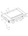
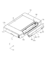
図1は本実施例に係るプリンターの斜視図であり、図2は本実施例に係るプリンターにおけるカバーを開いた状態を示す斜視図であり、図3は本発明に係るプリンターの側断面図であり、図4は本発明に係るプリンターの背面側を示す斜視図(バッテリー取り付け状態)であり、図5は本発明に係るプリンターの背面側を示す斜視図(バッテリー取り外し状態)である。 FIG. 1 is a perspective view of a printer according to the present embodiment, FIG. 2 is a perspective view illustrating a state where a cover of the printer according to the present embodiment is opened, and FIG. 3 is a side sectional view of the printer according to the present invention. FIG. 4 is a perspective view (battery attached state) showing the back side of the printer according to the present invention, and FIG. 5 is a perspective view (battery detached state) showing the back side of the printer according to the present invention.
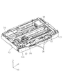
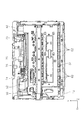
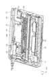
図6は本発明に係るプリンターの装置本体から切り欠き部を構成するフレームを取り外した状態を示す斜視図であり、図7は本発明に係るプリンターの装置本体の内部構造を示す斜視図であり、図8は本実施例に係るプリンターの装置本体の内部構造を示す平面図であり、図9は本実施例に係るプリンターの装置本体の内部構造を下方側から示した斜視図である。 FIG. 6 is a perspective view showing a state in which the frame constituting the cutout portion is removed from the apparatus main body of the printer according to the present invention, and FIG. 7 is a perspective view showing the internal structure of the apparatus main body of the printer according to the present invention. 8 is a plan view showing the internal structure of the apparatus main body of the printer according to the present embodiment. FIG. 9 is a perspective view showing the internal structure of the apparatus main body of the printer according to the present embodiment from the lower side.
尚、各図において示すX−Y−Z座標系はX方向が記録ヘッドの走査方向、Y方向が記録装置の奥行き方向、Z方向が記録ヘッドと媒体との間の距離(ギャップ)の変化する方向すなわち装置高さ方向を示している。尚、各図において−Y方向を装置前面側とし、+Y方向側を装置背面側とする。 In the XYZ coordinate system shown in each figure, the X direction is the scanning direction of the recording head, the Y direction is the depth direction of the recording apparatus, and the Z direction is the distance (gap) between the recording head and the medium. The direction, that is, the device height direction is shown. In each figure, the -Y direction is the front side of the apparatus, and the + Y direction side is the back side of the apparatus.
また、本明細書においてプリンター10の周囲を構成する側面のうち図1における装置前面(−Y方向側)を「第1面」とし、装置背面(+Y方向側)を「第2面」とし、装置右側面(−X方向側)を「第3面」とし、装置左側面(+X方向側)を「第4面」とする。さらにX軸方向を「第1の方向」とし、Y軸方向を「第2の方向」とする。
Further, in the present specification, among the side surfaces constituting the periphery of the
■■■記録装置の概要■■■■■■■■■■■■■■■■■
図1及び図2を参照しつつプリンター10の全体構成について概説する。プリンター10は、装置本体12と、媒体供給部カバー16と、記録部保護カバー18(図2参照)と、排出部カバー20と、操作部22(図2参照)と、バッテリー24と、を備えている。尚、バッテリー24については後ほど詳説する。
■■■ Overview of recording device ■■■■■■■■■■■■■■■■■
The overall configuration of the
また、装置本体12の上面12aには、媒体供給部カバー16が設けられている。媒体供給部カバー16は、装置本体12の上面12aに回動可能に取り付けられている。媒体供給部カバー16は、装置本体12に対して開いた状態(図2参照)と、閉じた状態(図1参照)とを取り得る。媒体供給部カバー16は装置本体12に対して閉じた状態にある場合、装置本体12の上面12aとともにプリンター10の上面を構成する。
A medium
また、媒体供給部カバー16は装置本体12に対して開いた状態(図2参照)にある場合、プリンター10の背面側(+Y方向側)に傾斜した状態となる。この状態において、媒体供給部カバー16の裏面は、媒体の載置面16aとして機能する。
Further, when the medium
また、媒体供給部カバー16が装置本体12に対して開いた状態にある場合、装置本体12の後述する媒体供給部26の媒体開口部28はプリンター10の上方に対して開いた状態となる。このため、媒体供給部26は、載置面16aに載置された媒体を後述する給送経路に給送可能となる。また、媒体開口部28には、プリンター10の幅方向(X軸方向)に接離移動可能に構成された一対の媒体ガイド30が設けられている。一対の媒体ガイド30は、媒体の幅方向における両端を拘束し、装置幅方向における媒体の位置を規定する。
When the medium
また、媒体供給部カバー16が装置本体12に対して開いた状態にある場合、プリンター10の上面において記録部保護カバー18及び操作部22が露出した状態となる。記録部保護カバー18は、装置本体12に対して開いた状態(図示せず)と閉じた状態(図2参照)とを取り得る。記録部保護カバー18が装置本体12に対して開いた状態にある場合、ユーザーは装置本体12に設けられた後述する記録部32にアクセス可能となる。
When the medium
また、操作部22は、プリンター10を操作するための電源ボタンや印刷設定ボタン等を備えて構成されている。媒体供給部カバー16が装置本体12に対して開いた状態にある場合、ユーザーが操作部22に対してアクセス可能となり、プリンター10の操作をすることができる。
The
さらに、装置本体12の前面12bには、排出部カバー20が設けられている。排出部カバー20は、装置本体12の前面12bに回動可能に取り付けられている。排出部カバー20は、装置本体12に対して開いた状態(図2参照)と、閉じた状態(図1参照)とを取り得る。排出部カバー20は、該排出部カバーが装置本体12に対して開いた状態にある場合、装置本体12の後述する「排出手段」としての排出部34から記録が実行された媒体をプリンター10の前方に排出する。
Further, a discharge unit cover 20 is provided on the
■■■媒体給送経路について■■■■■■■■■■■■■■■■■
次いで図3を参照しながらプリンター10における媒体給送経路上の構成要素についてさらに詳説する。図3において紙面右側(装置背面側)が給送経路上流であり、紙面左側(装置前面側)が給送経路下流となっている。
■■■ About the media feeding path ■■■■■■■■■■■■■■■■■
Next, the components on the medium feeding path in the
給送経路上流側には、装置本体12に対して開かれた状態の媒体供給部カバー16(図3一点鎖線部)の載置面16aから媒体を給送経路下流側に給送する媒体供給部26が設けられている。媒体供給部26は、媒体開口部28と、該媒体開口部に設けられた一対の媒体ガイド30と、媒体開口部28から投入された媒体の少なくとも一部を支持する媒体支持部36と、該媒体支持部36と対向する位置に設けられたピックアップローラー38と、戻しレバー40とを備えている。
On the upstream side of the feeding path, the medium is fed to feed the medium to the downstream side of the feeding path from the mounting
媒体支持部36は、図3において−Y方向側に向かって下がり傾斜状に形成されている。また、ピックアップローラー38は、媒体支持部36に載置された媒体に対して接離方向に揺動可能に構成されている。また、ピックアップローラー38は、「駆動用モーター」としての第1駆動モーター42(図6参照)から図示しない伝達機構を介して駆動力を受けて回転する。ピックアップローラー38は、媒体支持部36に接近する方向に変位した際、媒体支持部36に載置された最上位の媒体と接し、該最上位の媒体を給送経路下流側に給送する。この際、次位以降の媒体は、戻しレバー40により媒体支持部36に戻され、次位以降の媒体が不用意に給送経路下流側に給送されることを防止する。
The
媒体供給部26の下流側には搬送部44が設けられている。搬送部44は、搬送駆動ローラー46と、搬送従動ローラー48とを備えている。搬送駆動ローラー46は、搬送ローラー軸50に一体に取り付けられ、「駆動用モーター」としての第2駆動モーター52(図6参照)により搬送ローラー軸50とともに回転する。搬送部44は、媒体供給部26から給送された媒体を搬送駆動ローラー46と搬送従動ローラー48との間でニップして搬送方向下流側に搬送する。搬送部44の下流側には記録部32が設けられている。
A
記録部32は、キャリッジ54と、該キャリッジの底部に設けられた「記録手段」を構成する記録ヘッド56と、該記録ヘッドに対向し、媒体を支持する支持部としての下部案内部材すなわちプラテン58とを備えている。記録ヘッド56は、プラテン58に支持された媒体と対向する。キャリッジ54は、装置本体12内部に設けられた制御部(図示せず)により制御される第3駆動モーター60(図9参照)によって主走査方向(図3の紙面表裏方向すなわちX軸方向)に往復動する様に駆動される。また、プラテン58は、媒体を下方から支持することにより、媒体の記録面と記録ヘッド56のヘッド面との間の距離(ギャップ)を規定する。
The
記録部32の搬送方向下流側には、排出部34が設けられている。排出部34は、排出ローラー62を備えている。記録部32で記録が実行された媒体は、排出ローラー62により排出部34の下流側すなわち装置前方に向けて排出される。
A
■■■バッテリーについて■■■■■■■■■■■■■■■■■
次いで、図1、図3ないし図9を参照して本実施例に係るバッテリー24について詳説する。図5を参照するに、プリンター10は装置本体12の上面(図5における+Z方向側)と背面(図5における+Y方向側)とが成す角部に切り欠き部64が形成されている。図4と図5に示す様にバッテリー24は、切り欠き部64に対して着脱可能に取り付けられている。
■■■ Battery ■■■■■■■■■■■■■■■■■
Next, the
バッテリー24が切り欠き部64に取り付けられた状態において、バッテリー24の上面24aは、装置本体12の上面12aと面一になる。このため、バッテリー24の上面24aは、装置本体12の上面12aの一部を成している。また、バッテリー24の側面24bは、装置本体12の背面12cと面一になる。このため、バッテリー24の側面24bは、装置本体12の背面12cの一部を成している。
In a state where the
このため、前面12bを手前にした状態でプリンター10を上側から視認しても、切り欠き部64即ちバッテリー24の取付部位を視認することができ、バッテリー24の着脱作業を行うことができる。即ち、バッテリー24の着脱に際して背面12cを手前にすべく装置を回転させる必要がなく、これによってバッテリー24の着脱作業をより一層容易に行うことができる。さらに、バッテリー24が装置本体12に入り込んだ状態となる為、装置全体がより小型化されて、携帯性が良好となる。
For this reason, even when the
また、バッテリー24の装置本体12に対する装着状態において、当該バッテリー24の上面24aと装置本体12の上面12aとが面一であるので、装置本体12の上面12aに段差が形成されない。このため、プリンター10の携帯性及び美観を向上させることができる。
Further, when the
また、バッテリー24の装置本体12に対する装着状態において、当該バッテリー24の側面24bと装置本体12の背面12cとが面一であるので、背面12cに段差が形成されないことで、プリンター10の携帯性及び美観を向上させることができる。
In addition, since the
また、バッテリー24は、図4に示すように装置本体12の幅方向であるX軸方向において装置本体12の中央部に配置されている。このため、プリンター10においてX軸方向における装置全体の重量バランスが良好となり、プリンター10の携帯性が向上する。
Further, as shown in FIG. 4, the
また、バッテリー24は、リチウムイオン電池等の公知の電池であり、図示しないアダプター等により充電可能に構成されている。また、バッテリー24は、公知のロック機構(不図示)のロック解除を行うロック解除つまみ66を備えている。バッテリー24は、装置本体12の切り欠き部64に取り付けられた際、上記ロック機構によってロックされる。そしてロック解除つまみ66をスライドさせることによりロック解除できる。
The
また、図6及び図9を参照するに、バッテリー24は、X軸方向においてピックアップローラー38を駆動させる第1駆動モーター42と、搬送駆動ローラー46を駆動させる第2駆動モーター52との間に配置されている。この様にX軸方向においてバッテリー24の両側に第1駆動モーター42及び第2駆動モーター52が配置されているので、プリンター10においてX軸方向における装置全体の重量バランスが良好となり、プリンター10の携帯性を向上させることができる。
6 and 9, the
■■■回路基板について■■■■■■■■■■■■■■■■■
続いて、装置本体12に設けられた回路基板74とバッテリー24との関係について説明する。図5及び図6を参照するに切り欠き部64は、フレーム68を備えている。フレーム68は、装置本体12に取り付けられた際、切り欠き部64においてバッテリー24と対向する面を形成している。また、図6及び図7に示すように装置本体12は上部フレーム70と下部フレーム72とを備えている。切り欠き部64を構成するフレーム68は、装置本体12を構成する上部フレーム70及び下部フレーム72と別部材として構成されている。
■■■ About the circuit board ■■■■■■■■■■■■■■■■■
Next, the relationship between the
図8を参照するに装置本体12は、その内部に複数の電子部品が実装された回路基板74を備える。回路基板74は、その上面から+Z方向に所定量以上突出する複数の電子部品76を備えている。また、回路基板74は装置本体12内部において図6におけるXY平面に沿って延設されている。そして、再度図3を参照するに回路基板74は、図3におけるZ軸方向においてバッテリー24の−Z方向(下側)に配置されている。
Referring to FIG. 8, the apparatus
さらに、回路基板74は図3に示すようにY軸方向においてバッテリー24の下側から装置前面側(−Y方向側)に向かって延びている。また、回路基板74に実装された電子部品のうち回路基板74の上面から所定量以上突出する電子部品76は、Y軸方向において、回路基板74の−Y方向側である装置前面寄りの位置に配置されている。このため、電子部品76は、Z軸方向における占有領域がバッテリー24の占有領域と重なっている。
Further, as shown in FIG. 3, the
また、図3に示すようにY軸方向においてバッテリー24の−Y方向側には、−Y方向側に向かって下がり傾斜状に形成されている媒体支持部36が位置している。回路基板74の装置前面寄りに配置された電子部品76は、媒体支持部36の下側に形成された領域(デッドスペースとなる)に配置されている。
Further, as shown in FIG. 3, a
回路基板74に実装された複数の電子部品のうち回路基板74から上方に所定量以上突出する電子部品76が、Y軸方向においてバッテリー24に対して装置前面寄りの位置で、Z軸方向における占有領域がバッテリー24の占有領域と重なる様に配置されているので、回路基板74において所定量以上突出する電子部品76を、効率的に配置することができる。このため、装置の高さ寸法が大きくなることを抑制できる。
Of the plurality of electronic components mounted on the
また、給送前の媒体の少なくとも一部を支持する媒体支持部36は、−Y方向に向かって下がり傾斜状を成すので、当該媒体支持部36の下側には空き領域が生まれる。そしてこの空き領域に、回路基板74から所定量以上突出する電子部品76が配置されるので、前記空き領域を有効利用することで、装置全体の小型化に寄与することができる。
In addition, since the
また、図3及び図6に示すように回路基板74がバッテリー24の下側に配置されている。そして切り欠き部64を構成するフレーム68を装置本体12から取り外すと、回路基板74が装置本体12の外側からアクセス可能となる。
Further, as shown in FIGS. 3 and 6, a
切り欠き部64においてバッテリー24と対向する面を形成するフレーム68が、少なくとも装置本体12の上面12a及び背面12cを形成する上部フレーム70と別部材である。このため、バッテリー24の下側に配置された回路基板74及びその周囲にアクセスすることが容易となり、回路基板74まわりの配線作業を行うに際して作業性が向上する。
A
また、図3及び図9を参照するに、Z軸方向においてバッテリー24の下側には、インク貯留部78が設けられている。インク貯留部78は、記録ヘッド56のクリーニングを実行した際に記録ヘッド56から吐出されたインク及び媒体への縁なし印刷時に打ち捨てられたインクを回収手段(図示せず)を介して貯留する。
3 and 9, an
上記説明をまとめると本実施例におけるプリンター10は、装置本体12と、記録ヘッド56により記録の行われた媒体を排出する排出部34と、装置本体12の上面に着脱可能に設けられ、装着状態において装置本体12の上面12aの一部を成すバッテリー24と、を備える。
より詳しくは、本実施例では、装置本体12の周囲を構成する装置前面12bに対し反対側の面である装置背面12cの側から装置前面12bの側に向けて搬送される媒体に対し記録を行う記録ヘッド56を備える記録部32と、記録ヘッド56により記録の行われた媒体を装置前面12b側から排出する排出部34と、装置本体12の上面12aと背面12cとが成す角部に形成された切り欠き部64と、該切り欠き部64に着脱可能に設けられ、装着状態において装置本体12の上面12aの一部及び背面12cの一部を成すバッテリー24とを備える。
In summary, the
More specifically, in this embodiment, recording is performed on a medium conveyed from the device back
また、給送前の用紙の少なくとも一部を支持する、用紙給送方向に向かって下がり傾斜状を成す媒体支持部36を備え、記録ヘッド56とバッテリー24との間に媒体支持部36が配置されている。
In addition, a
また、複数の電子部品が実装された回路基板74を備え、複数の電子部品のうち少なくとも一部が、媒体支持部36とバッテリー24との間に位置する。
The
バッテリー24の装置本体12に対する装着状態において、当該バッテリー24の上面24aと装置本体12の上面12aとが面一である。また、バッテリー24の装置本体12に対する装着状態において、当該バッテリー24の側面24bと装置本体12の背面12cとが面一である。
When the
装置本体12の周囲を構成する、装置前面及び装置背面に対し交差する面を成す装置右側面からその反対側の装置左側面に向かう方向であるX軸方向において、バッテリー24は装置本体12の中央部に配置されている。また、装置本体12は少なくとも2つの駆動用モーターである第1駆動モーター42及び第2駆動モーター52を備える。第1駆動モーター42及び第2駆動モーター52は、X軸方向においてバッテリー24の両側に配置されている。
The
また回路基板74は、バッテリー24の下側に、バッテリー24の下面(X−Y平面に略平行)に沿った姿勢(即ち、X−Y平面に略平行)で配置され、回路基板74は、バッテリー74の下側から記録ヘッド56の側(Y−方向)に向かって延びる大きさを成している。そして複数の電子部品のうち回路基板74から上方に所定量以上突出する電子部品76が、回路基板74の平面方向においてバッテリー24の下側を避けた位置で、装置高さ方向における占有領域がバッテリー24の占有領域と重なる様に配置されている。
The
換言すれば、回路基板74は、装置本体12においてX軸方向と、装置前面から装置背面に向かう方向であるY軸方向と、を含むXY平面に沿った姿勢で、バッテリー24の下側に配置されている。Y軸方向において回路基板74は、バッテリー24の下側から装置前面の側に向かって延びる大きさを成している。前記複数の電子部品のうち回路基板74から上方に所定量以上突出する電子部品76が、Y軸方向においてバッテリー24に対し装置前面寄りの位置で、Z軸方向における占有領域がバッテリー24の占有領域と重なる様に配置されている。
In other words, the
記録部32がインクを吐出するインクジェット記録ヘッド56を備えて構成されている。
また、バッテリー24の下部に、インクジェット記録ヘッド56から打ち捨てられたインクを貯留するインク貯留部78を備える。
The
In addition, an
Y軸方向においてバッテリー24に対し装置前面寄りの位置に、給送前の媒体の少なくとも一部を支持する、−Y方向(用紙給送方向)に向かって下がり傾斜状を成す媒体支持部36を備える。回路基板74から所定量以上突出する電子部品76が、媒体支持部36の下側に形成された領域に配置されている。
また、切り欠き部64においてバッテリー24と対向する面を形成するフレーム68が、少なくとも装置本体12の上面12a及び装置背面12cを形成する上部フレーム70と別部材である。
A
In addition, the
また、本実施形態では本発明に係るバッテリー24を記録装置の一例としてのインクジェットプリンターに適用したが、その他液体噴射装置一般に適用することも可能である。
ここで、液体噴射装置とは、インクジェット式記録ヘッドが用いられ、該記録ヘッドからインクを吐出して被記録媒体に記録を行うプリンター、複写機及びファクシミリ等の記録装置に限らず、インクに代えてその用途に対応する液体を前記インクジェット式記録ヘッドに相当する液体噴射ヘッドから被記録媒体に相当する被噴射媒体に噴射して、前記液体を前記被噴射媒体に付着させる装置を含むものである。
In this embodiment, the
Here, the liquid ejecting apparatus uses an ink jet recording head, and is not limited to a recording apparatus such as a printer, a copier, and a facsimile machine that discharges ink from the recording head to perform recording on a recording medium. And a device for ejecting a liquid corresponding to the application from a liquid ejecting head corresponding to the ink jet recording head to an ejected medium corresponding to the recording medium, and attaching the liquid to the ejected medium.
液体噴射ヘッドとして、前記記録ヘッドの他に、液晶ディスプレー等のカラーフィルター製造に用いられる色材噴射ヘッド、有機ELディスプレーや面発光ディスプレー(FED)等の電極形成に用いられる電極材(導電ペースト)噴射ヘッド、バイオチップ製造に用いられる生体有機物噴射ヘッド、精密ピペットとしての試料噴射ヘッド等が挙げられる。 In addition to the recording head, as a liquid ejecting head, a color material ejecting head used for manufacturing a color filter such as a liquid crystal display, and an electrode material (conductive paste) used for forming an electrode such as an organic EL display or a surface emitting display (FED) Examples thereof include an ejection head, a bioorganic matter ejection head used for biochip production, and a sample ejection head as a precision pipette.
尚、本発明は上記実施例に限定されることなく、特許請求の範囲に記載した発明の範囲内で、種々の変形が可能であり、それらも本発明の範囲内に含まれるものであることは言うまでもない。
例えば、上記実施例ではバッテリー24を、装置本体12の上面12aと背面12cとに渡って設けたが、これに限られず、例えば上面12aのみに切り欠きを設け、そこに配置しても良い。即ち、バッテリー24が装着状態において装置本体12の背面12cを構成しなくても良い。
The present invention is not limited to the above-described embodiments, and various modifications can be made within the scope of the invention described in the claims, and these are also included in the scope of the present invention. Needless to say.
For example, in the above embodiment, the
10 プリンター、12 装置本体、12a、24a 上面、12b 前面、
12c 背面、16 媒体供給部カバー、16a 載置面、18 記録部保護カバー、
20 排出部カバー、22 操作部、24 バッテリー、24b 側面、
26 媒体供給部、28 媒体開口部、30 媒体ガイド、32 記録部、34 排出部、
36 媒体支持部、38 ピックアップローラー、40 戻しレバー、
42 第1駆動モーター、44 搬送部、46 搬送駆動ローラー、
48 搬送従動ローラー、50 搬送ローラー軸、52 第2駆動モーター、
54 キャリッジ、56 記録ヘッド、58 プラテン、60 第3駆動モーター、
62 排出ローラー、64 切り欠き部、66 ロック解除つまみ、68 フレーム、
70 上部フレーム、72 下部フレーム、74 回路基板、76 電子部品、
78 インク貯留部
10 printer, 12 device main body, 12a, 24a upper surface, 12b front surface,
12c rear surface, 16 medium supply unit cover, 16a mounting surface, 18 recording unit protective cover,
20 discharge part cover, 22 operation part, 24 battery, 24b side surface,
26 medium supply unit, 28 medium opening, 30 medium guide, 32 recording unit, 34 discharge unit,
36 Media support, 38 Pickup roller, 40 Return lever,
42 1st drive motor, 44 conveyance part, 46 conveyance drive roller,
48 transport driven roller, 50 transport roller shaft, 52 second drive motor,
54 Carriage, 56 Recording head, 58 Platen, 60 Third drive motor,
62 discharge roller, 64 notch, 66 unlocking knob, 68 frame,
70 upper frame, 72 lower frame, 74 circuit board, 76 electronic components,
78 Ink reservoir
Claims (7)
前記装置本体の上面に着脱可能に設けられ、装着状態において前記装置本体の上面の一部を成すバッテリーと、を備え、
前記バッテリーは、前記上面と、前記装置本体の周囲を構成する一の側面とが成す角部に形成された切欠き部に設けられ、
前記切り欠き部において前記バッテリーと対向する面を形成するフレームが、少なくとも前記上面および前記一の側面を形成するフレームと別部材である、ことを特徴とする記録装置。 An apparatus main body provided with a recording means for recording on a medium;
A battery which is detachably provided on the upper surface of the apparatus main body and forms a part of the upper surface of the apparatus main body in a mounted state
The battery is provided in a notch formed in a corner formed by the upper surface and one side surface constituting the periphery of the apparatus body ,
A recording apparatus, wherein a frame forming a surface facing the battery in the notch is a member different from at least the frame forming the upper surface and the one side surface .
前記装置本体の上面に着脱可能に設けられ、装着状態において前記装置本体の上面の一部を成すバッテリーと、 A battery that is detachably provided on the upper surface of the apparatus main body, and forms a part of the upper surface of the apparatus main body in a mounted state;
前記バッテリーにより前記媒体の給紙を行う第1駆動モーターと、前記媒体の搬送を行う第2駆動モーターと、を備え、A first drive motor that feeds the medium by the battery; and a second drive motor that transports the medium;
前記バッテリーは、前記上面と、前記装置本体の周囲を構成する一の側面とが成す角部に形成された切欠き部に設けられ、前記第1駆動モーターと第2駆動モーターの間に配置される、ことを特徴とする記録装置。The battery is provided in a notch formed at a corner formed by the upper surface and one side surface constituting the periphery of the apparatus main body, and is disposed between the first drive motor and the second drive motor. A recording apparatus.
前記装置本体の上面に着脱可能に設けられ、装着状態において前記装置本体の上面の一部を成すバッテリーと、 A battery that is detachably provided on the upper surface of the apparatus main body, and forms a part of the upper surface of the apparatus main body in a mounted state;
前記記録手段のメンタナンス時のインクを回収する貯留部と、が設けられ、A storage unit for collecting ink at the time of maintenance of the recording means,
前記バッテリーは、前記上面と、前記装置本体の周囲を構成する一の側面とが成す角部に形成された切欠き部に設けられ、The battery is provided in a notch formed in a corner formed by the upper surface and one side surface constituting the periphery of the apparatus body,
前記貯留部は、前記バッテリーの下方に位置することを特徴とする記録装置。The recording apparatus, wherein the storage unit is located below the battery.
前記媒体支持部に載置した前記媒体を供給する媒体供給部を備え、
前記記録手段と前記バッテリーとの間に前記媒体供給部が配置される、
ことを特徴とする記録装置。 4. The recording apparatus according to claim 1, wherein the medium support unit supports at least a part of the medium before feeding and is inclined downward toward the medium feeding direction.
A medium supply unit for supplying the medium placed on the medium support unit;
The medium supply unit is disposed between the recording means and the battery;
A recording apparatus.
前記複数の電子部品のうち少なくとも一部が、前記媒体供給部と前記バッテリーとの間
に位置する、
ことを特徴とする記録装置。 The recording apparatus according to claim 4, comprising a circuit board on which a plurality of electronic components are mounted,
At least a part of the plurality of electronic components is between the medium supply unit and the battery.
Located in the
A recording apparatus.
前記回路基板は、前記バッテリーの下側に、前記バッテリーの下面に沿った姿勢で配置 The circuit board is disposed below the battery in a posture along the lower surface of the battery.
され、And
前記回路基板は、前記バッテリーの下側から前記記録ヘッドの側に向かって延びる大き The circuit board extends from the lower side of the battery toward the recording head.
さを成し、Sachi,
前記複数の電子部品のうち前記回路基板から上方に所定量以上突出する電子部品が、前 Among the plurality of electronic components, an electronic component protruding upward by a predetermined amount from the circuit board is
記回路基板の平面方向において前記バッテリーの下側を避けた位置で、装置高さ方向におIn the plane direction of the circuit board, avoid the lower side of the battery,
ける占有領域が前記バッテリーの占有領域と重なる様に配置されている、Arranged to overlap the occupied area of the battery,
ことを特徴とする記録装置。A recording apparatus.
給送方向に向かって下がり傾斜状を成す媒体支持部を備え、A medium support portion that is inclined toward the feeding direction and has an inclined shape;
前記回路基板から所定量以上突出する電子部品が、前記媒体支持部の下側に形成された An electronic component protruding a predetermined amount or more from the circuit board is formed below the medium support portion.
領域に配置されている、Located in the area,
ことを特徴とする記録装置。A recording apparatus.
Priority Applications (3)
| Application Number | Priority Date | Filing Date | Title |
|---|---|---|---|
| JP2013071635A JP6201372B2 (en) | 2013-03-29 | 2013-03-29 | Recording device |
| US14/222,286 US9278560B2 (en) | 2013-03-29 | 2014-03-21 | Recording apparatus |
| CN201410122651.8A CN104070832B (en) | 2013-03-29 | 2014-03-28 | Recording equipment |
Applications Claiming Priority (1)
| Application Number | Priority Date | Filing Date | Title |
|---|---|---|---|
| JP2013071635A JP6201372B2 (en) | 2013-03-29 | 2013-03-29 | Recording device |
Publications (3)
| Publication Number | Publication Date |
|---|---|
| JP2014195904A JP2014195904A (en) | 2014-10-16 |
| JP2014195904A5 JP2014195904A5 (en) | 2016-04-28 |
| JP6201372B2 true JP6201372B2 (en) | 2017-09-27 |
Family
ID=51592607
Family Applications (1)
| Application Number | Title | Priority Date | Filing Date |
|---|---|---|---|
| JP2013071635A Active JP6201372B2 (en) | 2013-03-29 | 2013-03-29 | Recording device |
Country Status (3)
| Country | Link |
|---|---|
| US (1) | US9278560B2 (en) |
| JP (1) | JP6201372B2 (en) |
| CN (1) | CN104070832B (en) |
Families Citing this family (2)
| Publication number | Priority date | Publication date | Assignee | Title |
|---|---|---|---|---|
| JP6318616B2 (en) * | 2013-10-02 | 2018-05-09 | 株式会社リコー | Image forming apparatus |
| JP6770247B2 (en) * | 2016-06-15 | 2020-10-14 | セイコーエプソン株式会社 | Media feeder and image reader |
Family Cites Families (23)
| Publication number | Priority date | Publication date | Assignee | Title |
|---|---|---|---|---|
| US4759646A (en) * | 1986-04-24 | 1988-07-26 | Eastman Kodak Company | Compact battery-powered printer |
| EP0451460B1 (en) * | 1990-02-13 | 1997-12-29 | Canon Kabushiki Kaisha | Printing apparatus |
| US5049999A (en) * | 1990-07-02 | 1991-09-17 | Xerox Corporation | Compact multimode input and output scanner |
| EP0470545B1 (en) * | 1990-08-06 | 1998-06-03 | Canon Kabushiki Kaisha | Apparatus comprising a power source circuit including a charge circuit |
| JPH0492362A (en) * | 1990-08-06 | 1992-03-25 | Canon Inc | Battery and recording device |
| JPH06286266A (en) * | 1992-11-12 | 1994-10-11 | Seikosha Co Ltd | Printer |
| JPH07125285A (en) * | 1993-10-30 | 1995-05-16 | Asahi Optical Co Ltd | Printer |
| US6095700A (en) * | 1993-10-30 | 2000-08-01 | Asahi Kogaku Kogyo Kabushiki Kaisha | Battery operated thermal printer with means to optimize battery life |
| DE19605262C2 (en) * | 1995-02-07 | 1999-03-18 | Seiko Epson Corp | Printer with a housing and a feed device arranged thereon and a discharge device for single sheets |
| JP3445097B2 (en) * | 1996-08-12 | 2003-09-08 | キヤノン株式会社 | Printing equipment |
| JPH10244730A (en) * | 1997-03-06 | 1998-09-14 | Canon Inc | Recorder |
| JP3733239B2 (en) * | 1998-04-15 | 2006-01-11 | キヤノン株式会社 | Recording device |
| JP2000033748A (en) * | 1998-07-21 | 2000-02-02 | Hitachi Ltd | Thermal printer |
| JP3600173B2 (en) | 2000-03-14 | 2004-12-08 | オリンパス株式会社 | Portable printer device |
| US6618068B2 (en) * | 2000-03-14 | 2003-09-09 | Olympus Optical Co., Ltd. | Printer device |
| JP3335991B2 (en) * | 2000-08-21 | 2002-10-21 | オリンパス光学工業株式会社 | Printer device |
| JP2002086702A (en) * | 2000-09-12 | 2002-03-26 | Canon Inc | Recording mechanism, ink jet recording apparatus and imager with recording apparatus |
| JP4387651B2 (en) | 2002-10-07 | 2009-12-16 | キヤノン株式会社 | Recording device |
| US7370860B2 (en) * | 2004-09-29 | 2008-05-13 | Lexmark International, Inc. | Automatic edge guide assembly using springs and tapered surfaces |
| JP2006192777A (en) * | 2005-01-14 | 2006-07-27 | Seiko Epson Corp | Tape printer |
| JP4816542B2 (en) * | 2007-03-30 | 2011-11-16 | ブラザー工業株式会社 | Inkjet recording device |
| JP5251795B2 (en) * | 2009-09-03 | 2013-07-31 | ブラザー工業株式会社 | Enclosure for electrical equipment |
| CN202592968U (en) * | 2012-05-09 | 2012-12-12 | 上海济强电子科技有限公司 | Portable label printer |
-
2013
- 2013-03-29 JP JP2013071635A patent/JP6201372B2/en active Active
-
2014
- 2014-03-21 US US14/222,286 patent/US9278560B2/en active Active
- 2014-03-28 CN CN201410122651.8A patent/CN104070832B/en active Active
Also Published As
| Publication number | Publication date |
|---|---|
| US9278560B2 (en) | 2016-03-08 |
| JP2014195904A (en) | 2014-10-16 |
| CN104070832A (en) | 2014-10-01 |
| CN104070832B (en) | 2016-08-24 |
| US20140292897A1 (en) | 2014-10-02 |
Similar Documents
| Publication | Publication Date | Title |
|---|---|---|
| JP6019835B2 (en) | Recording device | |
| EP2163391B1 (en) | Printer | |
| JP4595425B2 (en) | Recording device | |
| US9415616B2 (en) | Recording apparatus | |
| US8807739B2 (en) | Recording apparatus | |
| US9724934B2 (en) | Recording apparatus | |
| JP6061062B2 (en) | Recording device | |
| JP6201372B2 (en) | Recording device | |
| JP6388107B2 (en) | Recording device | |
| JP6738039B2 (en) | Recording device | |
| US9987846B2 (en) | Recording apparatus | |
| JP6103869B2 (en) | Recording device | |
| US8317187B2 (en) | Recording apparatus | |
| JP6314677B2 (en) | Recording device | |
| JP4544406B2 (en) | Recording device | |
| JP6380742B2 (en) | Recording device | |
| JP5894730B2 (en) | Recording device | |
| JP6436285B2 (en) | Recording device | |
| JP4716003B2 (en) | Electronic equipment, recording device | |
| JP5724276B2 (en) | Recording device | |
| JP2012076899A (en) | Recording apparatus | |
| JP2006007730A (en) | Recording device and liquid jetting device | |
| JP2013146993A (en) | Recording apparatus | |
| JP2007038644A (en) | Carriage, recording apparatus, and liquid jetting device |
Legal Events
| Date | Code | Title | Description |
|---|---|---|---|
| RD04 | Notification of resignation of power of attorney |
Free format text: JAPANESE INTERMEDIATE CODE: A7424 Effective date: 20150113 |
|
| A521 | Request for written amendment filed |
Free format text: JAPANESE INTERMEDIATE CODE: A523 Effective date: 20160309 |
|
| A621 | Written request for application examination |
Free format text: JAPANESE INTERMEDIATE CODE: A621 Effective date: 20160309 |
|
| RD04 | Notification of resignation of power of attorney |
Free format text: JAPANESE INTERMEDIATE CODE: A7424 Effective date: 20160617 |
|
| RD03 | Notification of appointment of power of attorney |
Free format text: JAPANESE INTERMEDIATE CODE: A7423 Effective date: 20160624 |
|
| A131 | Notification of reasons for refusal |
Free format text: JAPANESE INTERMEDIATE CODE: A131 Effective date: 20161227 |
|
| A977 | Report on retrieval |
Free format text: JAPANESE INTERMEDIATE CODE: A971007 Effective date: 20161227 |
|
| A521 | Request for written amendment filed |
Free format text: JAPANESE INTERMEDIATE CODE: A523 Effective date: 20170214 |
|
| TRDD | Decision of grant or rejection written | ||
| A01 | Written decision to grant a patent or to grant a registration (utility model) |
Free format text: JAPANESE INTERMEDIATE CODE: A01 Effective date: 20170801 |
|
| A61 | First payment of annual fees (during grant procedure) |
Free format text: JAPANESE INTERMEDIATE CODE: A61 Effective date: 20170814 |
|
| R150 | Certificate of patent or registration of utility model |
Ref document number: 6201372 Country of ref document: JP Free format text: JAPANESE INTERMEDIATE CODE: R150 |