EP4011589A1 - Tire vulcanization device and method - Google Patents
Tire vulcanization device and method Download PDFInfo
- Publication number
- EP4011589A1 EP4011589A1 EP20850674.1A EP20850674A EP4011589A1 EP 4011589 A1 EP4011589 A1 EP 4011589A1 EP 20850674 A EP20850674 A EP 20850674A EP 4011589 A1 EP4011589 A1 EP 4011589A1
- Authority
- EP
- European Patent Office
- Prior art keywords
- plate
- bolster plate
- mold
- container ring
- side mold
- Prior art date
- Legal status (The legal status is an assumption and is not a legal conclusion. Google has not performed a legal analysis and makes no representation as to the accuracy of the status listed.)
- Granted
Links
Images




Classifications
-
- B—PERFORMING OPERATIONS; TRANSPORTING
- B29—WORKING OF PLASTICS; WORKING OF SUBSTANCES IN A PLASTIC STATE IN GENERAL
- B29C—SHAPING OR JOINING OF PLASTICS; SHAPING OF MATERIAL IN A PLASTIC STATE, NOT OTHERWISE PROVIDED FOR; AFTER-TREATMENT OF THE SHAPED PRODUCTS, e.g. REPAIRING
- B29C33/00—Moulds or cores; Details thereof or accessories therefor
- B29C33/02—Moulds or cores; Details thereof or accessories therefor with incorporated heating or cooling means
-
- B—PERFORMING OPERATIONS; TRANSPORTING
- B29—WORKING OF PLASTICS; WORKING OF SUBSTANCES IN A PLASTIC STATE IN GENERAL
- B29D—PRODUCING PARTICULAR ARTICLES FROM PLASTICS OR FROM SUBSTANCES IN A PLASTIC STATE
- B29D30/00—Producing pneumatic or solid tyres or parts thereof
- B29D30/06—Pneumatic tyres or parts thereof (e.g. produced by casting, moulding, compression moulding, injection moulding, centrifugal casting)
- B29D30/0601—Vulcanising tyres; Vulcanising presses for tyres
- B29D30/0605—Vulcanising presses characterised by moulds integral with the presses having radially movable sectors
-
- B—PERFORMING OPERATIONS; TRANSPORTING
- B29—WORKING OF PLASTICS; WORKING OF SUBSTANCES IN A PLASTIC STATE IN GENERAL
- B29C—SHAPING OR JOINING OF PLASTICS; SHAPING OF MATERIAL IN A PLASTIC STATE, NOT OTHERWISE PROVIDED FOR; AFTER-TREATMENT OF THE SHAPED PRODUCTS, e.g. REPAIRING
- B29C35/00—Heating, cooling or curing, e.g. crosslinking or vulcanising; Apparatus therefor
- B29C35/02—Heating or curing, e.g. crosslinking or vulcanizing during moulding, e.g. in a mould
-
- B—PERFORMING OPERATIONS; TRANSPORTING
- B30—PRESSES
- B30B—PRESSES IN GENERAL
- B30B1/00—Presses, using a press ram, characterised by the features of the drive therefor, pressure being transmitted directly, or through simple thrust or tension members only, to the press ram or platen
- B30B1/32—Presses, using a press ram, characterised by the features of the drive therefor, pressure being transmitted directly, or through simple thrust or tension members only, to the press ram or platen by plungers under fluid pressure
-
- B—PERFORMING OPERATIONS; TRANSPORTING
- B30—PRESSES
- B30B—PRESSES IN GENERAL
- B30B1/00—Presses, using a press ram, characterised by the features of the drive therefor, pressure being transmitted directly, or through simple thrust or tension members only, to the press ram or platen
- B30B1/40—Presses, using a press ram, characterised by the features of the drive therefor, pressure being transmitted directly, or through simple thrust or tension members only, to the press ram or platen by wedge means
-
- B—PERFORMING OPERATIONS; TRANSPORTING
- B29—WORKING OF PLASTICS; WORKING OF SUBSTANCES IN A PLASTIC STATE IN GENERAL
- B29D—PRODUCING PARTICULAR ARTICLES FROM PLASTICS OR FROM SUBSTANCES IN A PLASTIC STATE
- B29D30/00—Producing pneumatic or solid tyres or parts thereof
- B29D30/06—Pneumatic tyres or parts thereof (e.g. produced by casting, moulding, compression moulding, injection moulding, centrifugal casting)
- B29D30/0601—Vulcanising tyres; Vulcanising presses for tyres
- B29D30/0606—Vulcanising moulds not integral with vulcanising presses
- B29D2030/0607—Constructional features of the moulds
-
- B—PERFORMING OPERATIONS; TRANSPORTING
- B29—WORKING OF PLASTICS; WORKING OF SUBSTANCES IN A PLASTIC STATE IN GENERAL
- B29D—PRODUCING PARTICULAR ARTICLES FROM PLASTICS OR FROM SUBSTANCES IN A PLASTIC STATE
- B29D30/00—Producing pneumatic or solid tyres or parts thereof
- B29D30/06—Pneumatic tyres or parts thereof (e.g. produced by casting, moulding, compression moulding, injection moulding, centrifugal casting)
- B29D30/0601—Vulcanising tyres; Vulcanising presses for tyres
- B29D30/0606—Vulcanising moulds not integral with vulcanising presses
- B29D2030/0607—Constructional features of the moulds
- B29D2030/0609—Constructional features of the moulds the moulds being made of a plurality of laminations, e.g. thin plates, adjacent one another, so as to create the moulding cavity
-
- B—PERFORMING OPERATIONS; TRANSPORTING
- B29—WORKING OF PLASTICS; WORKING OF SUBSTANCES IN A PLASTIC STATE IN GENERAL
- B29D—PRODUCING PARTICULAR ARTICLES FROM PLASTICS OR FROM SUBSTANCES IN A PLASTIC STATE
- B29D30/00—Producing pneumatic or solid tyres or parts thereof
- B29D30/06—Pneumatic tyres or parts thereof (e.g. produced by casting, moulding, compression moulding, injection moulding, centrifugal casting)
- B29D30/0601—Vulcanising tyres; Vulcanising presses for tyres
- B29D30/0606—Vulcanising moulds not integral with vulcanising presses
- B29D2030/0607—Constructional features of the moulds
- B29D2030/0618—Annular elements, e.g. rings, for moulding the tyre shoulder areas
-
- B—PERFORMING OPERATIONS; TRANSPORTING
- B29—WORKING OF PLASTICS; WORKING OF SUBSTANCES IN A PLASTIC STATE IN GENERAL
- B29L—INDEXING SCHEME ASSOCIATED WITH SUBCLASS B29C, RELATING TO PARTICULAR ARTICLES
- B29L2030/00—Pneumatic or solid tyres or parts thereof
Definitions
- the present invention relates to a tire vulcanization device and a tire vulcanization method and particularly relates to a tire vulcanization device and a tire vulcanization method capable of more reliably closing a tire vulcanization mold and manufacturing a tire having excellent quality.
- a green tire is vulcanized in a closed mold.
- the sectional type mold is composed of an upper side mold, a lower side mold, and a plurality of sector molds, and the molds are closed so as to be in close contact with each other (see, for example, Patent Document 1).
- Each sector mold is pressed toward the center mechanism by a container ring that moves downward and is assembled in an annular shape.
- Each sector mold assembled in an annular shape and the lower side mold are assembled so as to be in close contact with each other.
- the upper side mold moves up and down together with an upper plate attached to the upper surface of the upper side mold. When the upper plate is placed below a bolster plate to which the container ring is attached, the upper surface of the upper plate is pressed downward by the bolster plate in a closed state of the mold.
- a gap is likely to occur between the lower surface of the bolster plate and the upper surface of the upper plate.
- the larger the gap the greater the amount of the upward movement of the upper side mold together with the upper plate when the green tire receives internal pressure during vulcanization, and a gap is created between the upper surface of each of the sector molds assembled in an annular shape and the lower surface of the upper side mold.
- the molds cannot be reliably maintained in a closed state without gaps.
- a step is formed on the upper side portion due to the gap between the upper surface of each of the sector molds and the lower surface of the upper side mold. There is room for improvement in improving the tire quality due to differences in the presence or absence of this step in the upper side portion and the lower side portion of the vulcanized tire.
- Patent Document 1 JP 63-54212 A
- An object of the present invention is to provide a tire vulcanization device and a tire vulcanization method capable of more reliably closing a tire vulcanization mold and manufacturing a tire having excellent quality.
- a tire vulcanization device includes: segments respectively attached to an outer circumferential surface of each of a plurality of sector molds disposed in an annular shape; an upper plate attached to an upper surface of an upper side mold; a lower plate attached to a lower surface of a lower side mold; a container ring disposed on an outer circumferential side of the segments; a bolster plate disposed above the upper plate and connected to the container ring; and a pressurizing mechanism configured to move the bolster plate up and down.
- the tire vulcanization device includes: a connecting body interposed between the bolster plate and the container ring to connect the bolster plate and the container ring; and a fluid supply unit configured to supply pressurizing fluid.
- the sector molds are assembled in an annular shape to be closed with the upper side mold pressed against upper surfaces of the sector molds.
- a tire vulcanization method includes: attaching segments respectively to an outer circumferential surface of each of a plurality of sector molds disposed in an annular shape; attaching an upper plate to an upper surface of an upper side mold; attaching a lower plate to a lower surface of a lower side mold; disposing a container ring on an outer circumferential side of the segments; disposing, above the upper plate, a bolster plate to which the container ring is connected; mounting a green tire onto the lower side mold in a sideways state; assembling the sector molds in an annular shape between the upper plate and the lower plate by moving downward, by a pressurizing mechanism, the bolster plate in a standby position to a mold closed position, and closing the sector molds with the sector molds vertically sandwiched between the upper side mold and the lower side mold to put the green tire inside; and vulcanizing the green tire by applying pressure and heat to the green tire.
- the sector molds are assembled in an annular shape to be closed with the upper side mold pressed against upper surfaces of the sector molds.
- the sector molds, the upper side mold, and the lower side mold are substantially closed. Additionally, by moving the container ring alone, which is held by the connecting body slidably in the vertical direction with respect to the bolster plate, downward with respect to the bolster plate by using the pressurizing fluid, the sector molds are assembled in an annular shape and closed with the upper side mold pressed against the upper surfaces of the sector molds.
- a tire vulcanization device 1 (hereinafter referred to as a vulcanization device 1) according to an embodiment of the present invention illustrated in FIGS. 1 to 3 includes a plurality of segments 6, an upper plate 2, a lower plate 4, a container ring 11, a bolster plate 3 connected to the container ring 11, a pressurizing mechanism 5 configured to move up and down the bolster plate 3, and a center mechanism 13 disposed in the center portion in a plan view of the lower plate 4. Further, the vulcanization device 1 includes an up down sliding mechanism 7 that can operate separately from the pressurizing mechanism 5 to slide the container ring 11 alone in the vertical direction with respect to the bolster plate 3.
- a tire vulcanization mold 15 (hereinafter referred to as a mold 15) is attached to the vulcanization device 1.
- the mold 15 includes an annular upper side mold 15a, an annular lower side mold 15b, and a plurality of sector molds 15c.
- a green tire T is disposed inside the mold 15 and mounted on the lower side mold 15b in a sideways state.
- FIGS. 1 and 3 illustrate the mold 15 in an opened state.
- a center post 12a constituting the center mechanism 12 is disposed at the center CL of the upper side mold 15a and the lower side mold 15b.
- Disc-shaped clamp portions 14 are attached at vertical intervals to the center post 12a.
- An upper end portion and a lower end portion of a cylindrical vulcanization bladder 13 are held by the respective clamp portions 14.
- An upper surface of the upper side mold 15a is attached to the upper plate 2 while facing a lower surface of the upper plate 2.
- the upper side mold 15a is configured such that an upper side portion Su of the green tire T in a sideways state is vulcanization molded by a lower surface of the upper side mold 15a.
- the upper plate 2 moves up and down together with the upper side mold 15a.
- a lower surface of the lower side mold 15b is attached to the lower plate 4 while facing an upper surface of the lower plate 4.
- the lower side mold 15b is configured such that a lower side portion Sd of the green tire T in a sideways state is vulcanization molded by an upper surface of the lower side mold 15b.
- the lower plate 4 is fixed in a stationary manner to the ground base.
- the segments 6 are arranged in an annular shape around the center mechanism 12 (the center CL).
- An outer circumferential surface of the sector mold 15c is attached to an inner circumferential side of each of the segments 6 while facing the inner circumferential side of the segment 6.
- the outer circumferential surface of each of the segments 6 has an inclination that inclines upward from the outer circumferential side toward the inner circumferential side.
- the sector mold 15c is configured such that a tread portion of the green tire T in a sideways state is vulcanization molded by an inner circumferential surface of the sector mold 15c.
- the annular container ring 11 is an annular body about the center mechanism 12 (the center CL) and moves up and down on the outer circumferential side of the segments 6 arranged in an annular shape.
- the container ring 11 moves up and down, and thus the inner circumferential inclined surface of the container ring 11 and the outer circumferential inclined surface of each of the segments 6 slide in contact with each other.
- the outer circumferential surface of each of the segments 6 is pressed by the inner circumferential surface of the container ring 11 moving downward, and thus each of the sector molds 15c moves close to the annular center CL together with the segment 6.
- the bolster plate 3 is disposed above the upper plate 2 and is connected via a connecting body 8 described below to an upper end portion of the container ring 11.
- the pressurizing mechanism 5 is connected to an upper surface of the bolster plate 3.
- a cylinder mechanism such as a hydraulic cylinder can be used as the pressurizing mechanism 5. Advance/retract movement of a cylinder rod of the pressurizing mechanism 5 in the vertical direction allows the bolster plate 3 to move up and down.
- the up down sliding mechanism 7 includes the connecting body 8 interposed between the bolster plate 3 and the container ring 11, a fluid supply unit 9 configured to supply pressurizing fluid F, and a control unit 10 configured to regulate a supply pressure of the pressurizing fluid F.
- the fluid supply unit 9 includes a supply source 9a including a storage tank for the pressurizing fluid F and a pumping driving mechanism, a supply line 9b extending from the supply source 9a, and a detachable portion 9c attached to a tip end of the supply line 9b.
- Various types of liquid such as hydraulic oil and water and various types of gas such as air can be used as the pressurizing fluid F, but a liquid that is non-compressible may be used. It is convenient to use the pressurizing fluid F flowing through a hydraulic pipe or an air pressure pipe that is provided preliminarily in the vulcanization device 1.
- the connecting body 8 includes an outer circumferential side engagement portion 8a and an inner circumferential side engagement portion 8a that protrude downward from a lower surface of the bolster plate 3, and an annular distance ring 8b protruding downward between the engagement portions 8a.
- the outer circumferential side engagement portion 8a and the inner circumferential side engagement portion 8a are disposed at four locations equally separated in the circumferential direction of the bolster plate 3.
- Each of the engagement portions 8a, 8 and the distance ring 8b are connected by a fixture 8e such as a bolt that extends through the outer circumferential side engagement portion 8a, the distance ring 8b, and the inner circumferential side engagement portion 8a to communicate therewith.
- the engagement portions 8a, 8a are disposed at four locations but not limited thereto, and are disposed, for example, at three or more locations.
- a lower end portion of the distance ring 8b is an annular protrusion, and the seal ring 8b extends in the circumferential direction on side surfaces of the annular protrusion.
- a flow path 8c through which the pressurizing fluid F flows is formed inside the distance ring 8b.
- the flow path 8c extends in an annular shape along the distance ring 8b as illustrated in FIG. 2 , and opens to a lower end surface of the distance ring 8b at a plurality of locations separated in the circumferential direction (at four locations, equal intervals of 90° in the circumferential direction in the present embodiment) as illustrated in FIG. 1 .
- the detachable portion 9c is detachably attached to an opening of the flow path 8c on an outer circumferential surface of the distance ring 8b.
- the detachable portion 9c is mounted to the opening, and thus the supply line 9b and the flow path 8c are brought into communication.
- the detachable portion 9c is mounted to the opening of the flow path 8c on the outer circumferential surface of the connecting body 8 when necessary, and does not need to be consistently mounted to the opening.
- annular groove portion 11a continuous entirely in the circumferential direction and engagement portions 11b protruding upward are formed on an upper surface of the container ring 11.
- An annular protrusion forming the lower end portion of the distance ring 8b is fit into the annular groove portion 11a.
- the annular protrusion is fit into the annular groove portion 11a, and thus an annular space having high airtightness (water tightness) and communicating with the flow path 8c is formed between a lower surface of the annular protrusion of the distance ring 8b and a bottom surface of the annular groove portion 11a of the container ring 11.
- the seal ring 8d can be provided on side surfaces of the annular groove portion 11a.
- the inner circumferential side engagement portion 11a and the outer circumferential side engagement portion 11b of the container ring 11 respectively engage with the corresponding engagement portions 8a, 8a of the connecting body 8.
- the distance ring 8b and the container ring 11 are vertically slidably connected by the respective engagement portions 8a, 8a.
- the container ring 11 is held by the connecting body 8 slidably in the vertical direction with respect to the bolster plate 3.
- the container ring 11 is suspended, under its own weight, by the connecting body 8 while having a predetermined maximum gap g1 in the vertical direction with respect to the connecting body 8.
- the container ring 11 is held slidably upward while being restricted from sliding downward with respect to the bolster plate 3.
- the pressurizing fluid F When the pressurizing fluid F is supplied by the fluid supply unit 9 through the supply line 9a to the flow path 8c of the connecting body 8, the supplied pressurizing fluid 8 accumulates between the lower surface of the annular protrusion of the distance ring 8b and the bottom surface of the annular groove portion 11a of the container ring 11.
- the container ring 11 In a case where the container ring 11 has a gap in the vertical direction with respect to the connecting body 8 that is smaller than the maximum gap g1 or where the container ring 11 is held by the connecting body 8 without a gap, the container ring 11 is moved downward with respect to the connecting body 8 (the bolster plate 3) by pressure generated by the supplied pressurizing fluid F.
- the container ring 11 moved downward By reducing the pressure (supply pressure) generated by the pressurizing fluid F or by releasing the pressure to the atmosphere, the container ring 11 moved downward moves upward.
- the green tire T in a sideways state is inserted through the center mechanism 12 with the mold 15 opened, and the green tire T is held by the vulcanization bladder 13 inflated by shaping pressure.
- the green tire T is mounted on the lower side mold 15b.
- the bolster plate 3 is in a standby position, and as described above, the container ring 11 is suspended by the connecting body 8 while having the predetermined gap g1 in the vertical direction with respect to the connecting body 8.
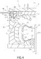
- the bolster plate 3 is moved downward by the pressurizing mechanism 5, and thus the upper plate 2, the upper side mold 15a, the connecting body 8, and the container rinng 11 are integrally moved downward. Accordingly, the segments 6 are mounted on the lower plate 4. In this step, the predetermined gap g1 in the vertical direction between the connecting body 8 and the container ring 11 is maintained.
- the bolster plate 3 is moved further downward by the pressurizing mechanism 5 to a mold closed position.
- the outer circumferential inclined surface of each of the segments 6 is pressed by the inner circumferential inclined surface of the container ring 11 moving downward, and each of the sector molds 15c is moved toward the center CL together with each of the segments 6.
- the upper side mold 15a presses an upper surface of each of the sector mold 15c moved toward the center CL.
- the sector molds 15c are assembled substantially in an annular shape vertically between the upper plate 2 and the lower plate 4 and vertically sandwiched by the upper side mold 15a and the lower side mold 15b, and the mold 15 is substantially closed with the green tire T contained therein.
- each of the sector molds 15c When the bolster plate 3 is in the mold closed position, the upper surface of each of the sector molds 15c is pressed by the upper side mold 15a, and each sector mold 15c is in pressure contact with the upper side mold 15a and the lower side mold 15b. The vertical position of the bolster plate 3 is maintained in the mold closed position.
- the container ring 11 pressed against the outer circumferential inclined surface of each of the segments 6 is sandwiched between the bolster plate 3 (connecting body 8) and the segments 6 and thus moves upward with respect to the bolster plate 3 (connecting body 8).
- the upward movement of the container ring 11 eliminates the gap g1 in the vertical direction between the container ring 11 and the connecting body 8.
- the container ring 11 is restricted from sliding upward with respect to the bolster plate 3 (connecting body 8) and is held slidably downward by the connecting body 8.
- the pressurizing fluid F is supplied from the fluid supply unit 9 to the flow path 8c of the connecting body 8 in a state where the bolster plate 3 is maintained in the mold closed position.
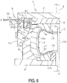
- the container ring 11 is moved downward alone with respect to the bolster plate 3 (connecting body 8) by the pressure of the supplied pressurizing fluid F.
- the container ring 11 moves downward with respect to the bolster plate 3 (connecting body 8), and thus a gap g2 occurs between the container ring 11 and the connecting body 8 in the vertical direction (gap g2 ⁇ gap g1).
- the segments 6 are pressed toward the center CL, and the sector molds 15c are firmly assembled in an annular shape.
- the sector molds 15c assembled in an annular shape are further tightened by using the up down sliding mechanism 7. Accordingly, the sector molds 15c are firmly assembled in an annular shape to be closed with the upper side mold 15a pressed against the upper surface of each of the sector molds 15c.
- the vulcanization bladder 13 is further inflated inside the green tire T to apply predetermined internal pressure to the green tire T, and the green tire T is heated and vulcanized at a predetermined temperature.
- a pneumatic tire is obtained by vulcanizing the green tire T for a predetermined time.
- the force that attempts to open the mold 15 acts from the inner side of the closed mold 15, but the force to open the mold is counteracted by mold closing force generated by the pressurizing mechanism 5 and the up down sliding mechanism 7.
- the amount of downward movement (size of the gap g2) of the container ring 11 with respect to the bolster plate 3 (connecting body 8) can be adjusted by regulating the supply pressure of the pressurizing fluid F by the control unit 10. Accordingly, the supply pressure of the pressurizing fluid F may be regulated in an appropriate range based on the pre-grasped vulcanization conditions or the like of the green tire T to be vulcanized.
- the sector molds 15c can be firmly assembled in an annular shape without the gap.
- the vertical position of the bolster plate 3 is maintained in the mold closed position. Accordingly, a close contact state between the sector molds 15c and the upper side mold 15a and between the sector molds 15c and the lower side mold 15b is maintained.
- the mold 15 can reliably be in the closed state during vulcanization.
- the pressurizing fluid F may be supplied to the flow path 8c when necessary.
- an unnecessary load is not consistently applied to the container ring 11, the connecting body 8, the bolster plate 3, and other components, which advantageously prevents deformation, wear, or the like of components.
- the amount of downward movement of the container ring 11, that is, more tightening force with respect to the sector molds 15c to be assembled in an annular shape can be changed, and advantageously, the degree of change can be widely extended.
- the mold closing force can be appropriately set by the pressurizing mechanism 5 and the up down sliding mechanism 7 in a balanced manner, and thus advantageously, the mold 15 is reliably maintained in the closed state.
- the container ring 11 is moved downward alone with respect to the bolster plate 3 (connecting body 8) by using a biasing force of a spring or the like, the aforementioned advantage from using the pressurizing fluid F cannot be obtained.
- the up down sliding mechanism 7 is not limited to the embodiment described above. Various configurations can be used as the up down sliding mechanism 7, where the container ring 11 can be moved downward alone with respect to the bolster plate 3 by the pressurizing fluid F in a state where the container ring 11 is held slidably in the vertical direction with respect to the bolster plate 3 and the vertical position of the bolster plate 3 is maintained in the mold closed position.
- the supply line 9b through which the pressurizing fluid F is supplied is connected at one location to the connecting body 8; however, the supply line 9b can be connected at a plurality of locations separated in the circumferential direction of the connecting body 8. This makes it easier to apply the force, pressing the annular container ring 11 by the pressurizing fluid F, evenly in the circumferential direction.
- the supply line 9b in a case where the supply line 9b is configured to be connected at one location to the connecting body 8, attaching/detaching operation of the detachable portion 9c is performed only at one location, and thus the operation is simplified.
- the supply source 9a is not limited to a single source, and the pressurizing fluid F can be supplied from a plurality of supply sources 9a to the flow path 8b.
Landscapes
- Engineering & Computer Science (AREA)
- Mechanical Engineering (AREA)
- Physics & Mathematics (AREA)
- Health & Medical Sciences (AREA)
- Oral & Maxillofacial Surgery (AREA)
- Thermal Sciences (AREA)
- Fluid Mechanics (AREA)
- Moulds For Moulding Plastics Or The Like (AREA)
- Heating, Cooling, Or Curing Plastics Or The Like In General (AREA)
Abstract
Description
- The present invention relates to a tire vulcanization device and a tire vulcanization method and particularly relates to a tire vulcanization device and a tire vulcanization method capable of more reliably closing a tire vulcanization mold and manufacturing a tire having excellent quality.
- In manufacturing a tire, a green tire is vulcanized in a closed mold. The sectional type mold is composed of an upper side mold, a lower side mold, and a plurality of sector molds, and the molds are closed so as to be in close contact with each other (see, for example, Patent Document 1).
- Each sector mold is pressed toward the center mechanism by a container ring that moves downward and is assembled in an annular shape. Each sector mold assembled in an annular shape and the lower side mold are assembled so as to be in close contact with each other. On the other hand, the upper side mold moves up and down together with an upper plate attached to the upper surface of the upper side mold. When the upper plate is placed below a bolster plate to which the container ring is attached, the upper surface of the upper plate is pressed downward by the bolster plate in a closed state of the mold.
- When a gap occurs between the sector molds in the closed state of the mold, unvulcanized rubber of the green tire disposed lying sideways inside the mold flows out from the gap, which affects the quality of the vulcanized tire. Therefore, in the vulcanization device having this structure, it is necessary to press the sector molds more strongly by the container ring in order to prevent the occurrence of a gap between the sector molds. To achieve this, in closing the molds, the downward movement of the bolster plate needs to not be restricted by the upper plate, and pressing on each sector mold by the container ring is prioritized over pressing on the upper plate by the bolster plate.
- Accordingly, a gap is likely to occur between the lower surface of the bolster plate and the upper surface of the upper plate. The larger the gap, the greater the amount of the upward movement of the upper side mold together with the upper plate when the green tire receives internal pressure during vulcanization, and a gap is created between the upper surface of each of the sector molds assembled in an annular shape and the lower surface of the upper side mold. In other words, the molds cannot be reliably maintained in a closed state without gaps. As a result, in the vulcanized tire, a step is formed on the upper side portion due to the gap between the upper surface of each of the sector molds and the lower surface of the upper side mold. There is room for improvement in improving the tire quality due to differences in the presence or absence of this step in the upper side portion and the lower side portion of the vulcanized tire.
- Patent Document 1:
JP 63-54212 A - An object of the present invention is to provide a tire vulcanization device and a tire vulcanization method capable of more reliably closing a tire vulcanization mold and manufacturing a tire having excellent quality.
- In order to achieve the object described above, a tire vulcanization device according to an embodiment of the present invention includes: segments respectively attached to an outer circumferential surface of each of a plurality of sector molds disposed in an annular shape; an upper plate attached to an upper surface of an upper side mold; a lower plate attached to a lower surface of a lower side mold; a container ring disposed on an outer circumferential side of the segments; a bolster plate disposed above the upper plate and connected to the container ring; and a pressurizing mechanism configured to move the bolster plate up and down. By moving the bolster plate downward, the sector molds are assembled in an annular shape between the upper plate and the lower plate, and the sector molds are closed while being vertically sandwiched between the upper side mold and the lower side mold. The tire vulcanization device includes: a connecting body interposed between the bolster plate and the container ring to connect the bolster plate and the container ring; and a fluid supply unit configured to supply pressurizing fluid. In a state where the container ring is held slidably in a vertical direction with respect to the bolster plate by the connecting body and a vertical position of the bolster plate is maintained in a mold closed position, by moving the container ring downward with respect to the bolster plate by the pressurizing fluid supplied by the fluid supply unit, the sector molds are assembled in an annular shape to be closed with the upper side mold pressed against upper surfaces of the sector molds.
- A tire vulcanization method according to an embodiment of the present invention includes: attaching segments respectively to an outer circumferential surface of each of a plurality of sector molds disposed in an annular shape; attaching an upper plate to an upper surface of an upper side mold; attaching a lower plate to a lower surface of a lower side mold; disposing a container ring on an outer circumferential side of the segments; disposing, above the upper plate, a bolster plate to which the container ring is connected; mounting a green tire onto the lower side mold in a sideways state; assembling the sector molds in an annular shape between the upper plate and the lower plate by moving downward, by a pressurizing mechanism, the bolster plate in a standby position to a mold closed position, and closing the sector molds with the sector molds vertically sandwiched between the upper side mold and the lower side mold to put the green tire inside; and vulcanizing the green tire by applying pressure and heat to the green tire. In a state where the bolster plate is moved downward from the standby position and held in the mold closed position by connecting the bolster plate and the container ring with a connecting body interposed between the bolster plate and the container ring and allowing the container ring to be held slidably, by the connecting body, in a vertical direction with respect to the bolster plate, by moving the container ring downward with respect to the bolster plate by pressurizing fluid supplied from a fluid supply unit, the sector molds are assembled in an annular shape to be closed with the upper side mold pressed against upper surfaces of the sector molds.
- According to an embodiment of the present invention, by moving the bolster plate downward by using the pressurizing mechanism and maintaining the bolster plate in the mold closed position, the sector molds, the upper side mold, and the lower side mold are substantially closed. Additionally, by moving the container ring alone, which is held by the connecting body slidably in the vertical direction with respect to the bolster plate, downward with respect to the bolster plate by using the pressurizing fluid, the sector molds are assembled in an annular shape and closed with the upper side mold pressed against the upper surfaces of the sector molds. As a result, in a state where the sector molds are pressed against the upper side mold and the lower side mold and sandwiched therebetween with the bolster plate maintained in the mold closed position, even in a case where there may be a gap between the adjacent sector molds in the circumferential direction, by moving the container ring alone further downward, the sector molds can be assembled in an annular shape without the gap. At this time, since a vertical position of the bolster plate is maintained in the mold closed position, the molds can reliably be in the closed state. Accordingly, differences of the finish of both side portions of a tire rarely occur in a vulcanization step, and the tire having excellent quality can be manufactured.
-
-
FIG. 1 is an explanatory diagram illustrating, in a longitudinal cross-sectional view, the left half of a tire vulcanization device according to an embodiment of the present invention in a mold opened state. -
FIG. 2 is an explanatory diagram illustrating a connecting body and a container ring ofFIG. 1 in a plan view. -
FIG. 3 is an explanatory diagram illustrating sector molds and segments ofFIG. 1 in a plan view. -
FIG. 4 is an explanatory diagram illustrating, in a longitudinal cross-sectional view, a state where a bolster plate ofFIG. 1 is moved downward and each of the segments is placed on a lower plate. -
FIG. 5 is an explanatory diagram illustrating, in a longitudinal cross-sectional view, a state where the bolster plate ofFIG. 4 is moved further downward to a mold closed position. -
FIG. 6 is an explanatory diagram illustrating, in a longitudinal cross-sectional view, a state where the container ring is moved further downward and the molds are closed. -
FIG. 7 is an explanatory diagram illustrating the sector molds and the segments ofFIG. 6 in a plan view. - Hereinafter, a tire vulcanization device and a tire vulcanization method of the present invention will be described based on an embodiment illustrated in the drawings.
- A tire vulcanization device 1 (hereinafter referred to as a vulcanization device 1) according to an embodiment of the present invention illustrated in
FIGS. 1 to 3 includes a plurality ofsegments 6, anupper plate 2, alower plate 4, acontainer ring 11, abolster plate 3 connected to thecontainer ring 11, apressurizing mechanism 5 configured to move up and down thebolster plate 3, and acenter mechanism 13 disposed in the center portion in a plan view of thelower plate 4. Further, thevulcanization device 1 includes an up down slidingmechanism 7 that can operate separately from the pressurizingmechanism 5 to slide thecontainer ring 11 alone in the vertical direction with respect to thebolster plate 3. - A tire vulcanization mold 15 (hereinafter referred to as a mold 15) is attached to the
vulcanization device 1. Themold 15 includes an annularupper side mold 15a, an annularlower side mold 15b, and a plurality ofsector molds 15c. A green tire T is disposed inside themold 15 and mounted on thelower side mold 15b in a sideways state.FIGS. 1 and3 illustrate themold 15 in an opened state. - A
center post 12a constituting thecenter mechanism 12 is disposed at the center CL of theupper side mold 15a and thelower side mold 15b. Disc-shaped clamp portions 14 are attached at vertical intervals to thecenter post 12a. An upper end portion and a lower end portion of acylindrical vulcanization bladder 13 are held by therespective clamp portions 14. - An upper surface of the
upper side mold 15a is attached to theupper plate 2 while facing a lower surface of theupper plate 2. Theupper side mold 15a is configured such that an upper side portion Su of the green tire T in a sideways state is vulcanization molded by a lower surface of theupper side mold 15a. Theupper plate 2 moves up and down together with theupper side mold 15a. - A lower surface of the
lower side mold 15b is attached to thelower plate 4 while facing an upper surface of thelower plate 4. Thelower side mold 15b is configured such that a lower side portion Sd of the green tire T in a sideways state is vulcanization molded by an upper surface of thelower side mold 15b. Thelower plate 4 is fixed in a stationary manner to the ground base. - The
segments 6 are arranged in an annular shape around the center mechanism 12 (the center CL). An outer circumferential surface of thesector mold 15c is attached to an inner circumferential side of each of thesegments 6 while facing the inner circumferential side of thesegment 6. The outer circumferential surface of each of thesegments 6 has an inclination that inclines upward from the outer circumferential side toward the inner circumferential side. Thesector mold 15c is configured such that a tread portion of the green tire T in a sideways state is vulcanization molded by an inner circumferential surface of thesector mold 15c. - The
annular container ring 11 is an annular body about the center mechanism 12 (the center CL) and moves up and down on the outer circumferential side of thesegments 6 arranged in an annular shape. Thecontainer ring 11 moves up and down, and thus the inner circumferential inclined surface of thecontainer ring 11 and the outer circumferential inclined surface of each of thesegments 6 slide in contact with each other. Then, the outer circumferential surface of each of thesegments 6 is pressed by the inner circumferential surface of thecontainer ring 11 moving downward, and thus each of thesector molds 15c moves close to the annular center CL together with thesegment 6. - The bolster
plate 3 is disposed above theupper plate 2 and is connected via a connectingbody 8 described below to an upper end portion of thecontainer ring 11. Thepressurizing mechanism 5 is connected to an upper surface of the bolsterplate 3. A cylinder mechanism such as a hydraulic cylinder can be used as thepressurizing mechanism 5. Advance/retract movement of a cylinder rod of thepressurizing mechanism 5 in the vertical direction allows the bolsterplate 3 to move up and down. - In the present embodiment, the up down sliding
mechanism 7 includes the connectingbody 8 interposed between the bolsterplate 3 and thecontainer ring 11, a fluid supply unit 9 configured to supply pressurizing fluid F, and acontrol unit 10 configured to regulate a supply pressure of the pressurizing fluid F. The fluid supply unit 9 includes asupply source 9a including a storage tank for the pressurizing fluid F and a pumping driving mechanism, asupply line 9b extending from thesupply source 9a, and adetachable portion 9c attached to a tip end of thesupply line 9b. Various types of liquid such as hydraulic oil and water and various types of gas such as air can be used as the pressurizing fluid F, but a liquid that is non-compressible may be used. It is convenient to use the pressurizing fluid F flowing through a hydraulic pipe or an air pressure pipe that is provided preliminarily in thevulcanization device 1. - The connecting
body 8 includes an outer circumferentialside engagement portion 8a and an inner circumferentialside engagement portion 8a that protrude downward from a lower surface of the bolsterplate 3, and anannular distance ring 8b protruding downward between theengagement portions 8a. The outer circumferentialside engagement portion 8a and the inner circumferentialside engagement portion 8a are disposed at four locations equally separated in the circumferential direction of the bolsterplate 3. Each of theengagement portions distance ring 8b are connected by afixture 8e such as a bolt that extends through the outer circumferentialside engagement portion 8a, thedistance ring 8b, and the inner circumferentialside engagement portion 8a to communicate therewith. Theengagement portions distance ring 8b is an annular protrusion, and theseal ring 8b extends in the circumferential direction on side surfaces of the annular protrusion. - In addition, a
flow path 8c through which the pressurizing fluid F flows is formed inside thedistance ring 8b. Theflow path 8c extends in an annular shape along thedistance ring 8b as illustrated inFIG. 2 , and opens to a lower end surface of thedistance ring 8b at a plurality of locations separated in the circumferential direction (at four locations, equal intervals of 90° in the circumferential direction in the present embodiment) as illustrated inFIG. 1 . Thedetachable portion 9c is detachably attached to an opening of theflow path 8c on an outer circumferential surface of thedistance ring 8b. Thedetachable portion 9c is mounted to the opening, and thus thesupply line 9b and theflow path 8c are brought into communication. Thedetachable portion 9c is mounted to the opening of theflow path 8c on the outer circumferential surface of the connectingbody 8 when necessary, and does not need to be consistently mounted to the opening. - An
annular groove portion 11a continuous entirely in the circumferential direction andengagement portions 11b protruding upward are formed on an upper surface of thecontainer ring 11. An annular protrusion forming the lower end portion of thedistance ring 8b is fit into theannular groove portion 11a. The annular protrusion is fit into theannular groove portion 11a, and thus an annular space having high airtightness (water tightness) and communicating with theflow path 8c is formed between a lower surface of the annular protrusion of thedistance ring 8b and a bottom surface of theannular groove portion 11a of thecontainer ring 11. Note that theseal ring 8d can be provided on side surfaces of theannular groove portion 11a. - The inner circumferential
side engagement portion 11a and the outer circumferentialside engagement portion 11b of thecontainer ring 11 respectively engage with thecorresponding engagement portions body 8. As a result, thedistance ring 8b and thecontainer ring 11 are vertically slidably connected by therespective engagement portions container ring 11 is held by the connectingbody 8 slidably in the vertical direction with respect to the bolsterplate 3. In the mold opened state illustrated inFIG. 1 , thecontainer ring 11 is suspended, under its own weight, by the connectingbody 8 while having a predetermined maximum gap g1 in the vertical direction with respect to the connectingbody 8. As a result, thecontainer ring 11 is held slidably upward while being restricted from sliding downward with respect to the bolsterplate 3. - When the pressurizing fluid F is supplied by the fluid supply unit 9 through the
supply line 9a to theflow path 8c of the connectingbody 8, the supplied pressurizingfluid 8 accumulates between the lower surface of the annular protrusion of thedistance ring 8b and the bottom surface of theannular groove portion 11a of thecontainer ring 11. In a case where thecontainer ring 11 has a gap in the vertical direction with respect to the connectingbody 8 that is smaller than the maximum gap g1 or where thecontainer ring 11 is held by the connectingbody 8 without a gap, thecontainer ring 11 is moved downward with respect to the connecting body 8 (the bolster plate 3) by pressure generated by the supplied pressurizing fluid F. By reducing the pressure (supply pressure) generated by the pressurizing fluid F or by releasing the pressure to the atmosphere, thecontainer ring 11 moved downward moves upward. - Next, an example of a method of manufacturing a pneumatic tire by vulcanizing the green tire T using this
vulcanization device 1 will be described. - In vulcanizing the green tire T, as illustrated in
FIGS. 1 and3 , the green tire T in a sideways state is inserted through thecenter mechanism 12 with themold 15 opened, and the green tire T is held by thevulcanization bladder 13 inflated by shaping pressure. The green tire T is mounted on thelower side mold 15b. At this time, the bolsterplate 3 is in a standby position, and as described above, thecontainer ring 11 is suspended by the connectingbody 8 while having the predetermined gap g1 in the vertical direction with respect to the connectingbody 8. - Next, as illustrated in
FIG. 4 , the bolsterplate 3 is moved downward by thepressurizing mechanism 5, and thus theupper plate 2, theupper side mold 15a, the connectingbody 8, and thecontainer rinng 11 are integrally moved downward. Accordingly, thesegments 6 are mounted on thelower plate 4. In this step, the predetermined gap g1 in the vertical direction between the connectingbody 8 and thecontainer ring 11 is maintained. - Next, as illustrated in
FIG. 5 , the bolsterplate 3 is moved further downward by thepressurizing mechanism 5 to a mold closed position. In this step, the outer circumferential inclined surface of each of thesegments 6 is pressed by the inner circumferential inclined surface of thecontainer ring 11 moving downward, and each of thesector molds 15c is moved toward the center CL together with each of thesegments 6. - In addition, since the
upper plate 2 and theupper side mold 15a integrally move downward together with the bolsterplate 3, theupper side mold 15a presses an upper surface of each of thesector mold 15c moved toward the center CL. As a result, thesector molds 15c are assembled substantially in an annular shape vertically between theupper plate 2 and thelower plate 4 and vertically sandwiched by theupper side mold 15a and thelower side mold 15b, and themold 15 is substantially closed with the green tire T contained therein. - When the bolster
plate 3 is in the mold closed position, the upper surface of each of thesector molds 15c is pressed by theupper side mold 15a, and eachsector mold 15c is in pressure contact with theupper side mold 15a and thelower side mold 15b. The vertical position of the bolsterplate 3 is maintained in the mold closed position. - The
container ring 11 pressed against the outer circumferential inclined surface of each of thesegments 6 is sandwiched between the bolster plate 3 (connecting body 8) and thesegments 6 and thus moves upward with respect to the bolster plate 3 (connecting body 8). The upward movement of thecontainer ring 11 eliminates the gap g1 in the vertical direction between thecontainer ring 11 and the connectingbody 8. As a result, when the bolsterplate 3 is in the mold closed position, thecontainer ring 11 is restricted from sliding upward with respect to the bolster plate 3 (connecting body 8) and is held slidably downward by the connectingbody 8. - In this state, the
sector molds 15c, theupper side mold 15a, and thelower side mold 15b are sufficiently pressed; however, thesector molds 15c adjacent to each other in the circumferential direction may not be firmly assembled without a gap. Accordingly, as illustrated inFIG. 6 , the pressurizing fluid F is supplied from the fluid supply unit 9 to theflow path 8c of the connectingbody 8 in a state where the bolsterplate 3 is maintained in the mold closed position. Thecontainer ring 11 is moved downward alone with respect to the bolster plate 3 (connecting body 8) by the pressure of the supplied pressurizing fluid F. InFIG. 6 , thecontainer ring 11 moves downward with respect to the bolster plate 3 (connecting body 8), and thus a gap g2 occurs between thecontainer ring 11 and the connectingbody 8 in the vertical direction (gap g2 ≤ gap g1). - In accordance with the downward movement of the
container ring 11, the segments 6 (sector molds 15c) are pressed toward the center CL, and thesector molds 15c are firmly assembled in an annular shape. In other words, thesector molds 15c assembled in an annular shape are further tightened by using the up down slidingmechanism 7. Accordingly, thesector molds 15c are firmly assembled in an annular shape to be closed with theupper side mold 15a pressed against the upper surface of each of thesector molds 15c. - With the mold closed state maintained, inside the
closed mold 15, thevulcanization bladder 13 is further inflated inside the green tire T to apply predetermined internal pressure to the green tire T, and the green tire T is heated and vulcanized at a predetermined temperature. A pneumatic tire is obtained by vulcanizing the green tire T for a predetermined time. - During vulcanization of the green tire T, the force that attempts to open the
mold 15 acts from the inner side of theclosed mold 15, but the force to open the mold is counteracted by mold closing force generated by thepressurizing mechanism 5 and the up down slidingmechanism 7. The amount of downward movement (size of the gap g2) of thecontainer ring 11 with respect to the bolster plate 3 (connecting body 8) can be adjusted by regulating the supply pressure of the pressurizing fluid F by thecontrol unit 10. Accordingly, the supply pressure of the pressurizing fluid F may be regulated in an appropriate range based on the pre-grasped vulcanization conditions or the like of the green tire T to be vulcanized. - Even in a case where there is a gap between the
sector molds 15c adjacent to each other in the circumferential direction when the bolsterplate 3 is moved downward to a mold closed position by using thepressurizing mechanism 5 to substantially close themold 15 as just described, by moving thecontainer ring 11 alone downward by using the up down slidingmechanism 7, thesector molds 15c can be firmly assembled in an annular shape without the gap. In addition, even when thesector molds 15c are pressed toward the center CL by using the up down slidingmechanism 7, the vertical position of the bolsterplate 3 is maintained in the mold closed position. Accordingly, a close contact state between thesector molds 15c and theupper side mold 15a and between thesector molds 15c and thelower side mold 15b is maintained. Thus, as illustrated inFIG. 7 , themold 15 can reliably be in the closed state during vulcanization. - As a result, a defect such that a step is formed due to a failure of the upper side portion Su of the manufactured tire can be avoided. That is, a difference in the finish of both side portions of the tire rarely occurs during the vulcanization step, and a tire having excellent quality can be manufactured. In addition, the formation of unnecessary rubber membranes due to the outflow of rubber from gaps between the
sector molds 15c can also be suppressed, and thus appearance quality of the tire can be improved. - Since the configuration is provided where the pressurizing fluid F is used in moving the
container ring 11 alone downward with respect to the bolster plate 3 (connecting body 8), the pressurizing fluid F may be supplied to theflow path 8c when necessary. As a result, an unnecessary load is not consistently applied to thecontainer ring 11, the connectingbody 8, the bolsterplate 3, and other components, which advantageously prevents deformation, wear, or the like of components. In addition, by simply adjusting the supply pressure of the pressurizing fluid F, the amount of downward movement of thecontainer ring 11, that is, more tightening force with respect to thesector molds 15c to be assembled in an annular shape can be changed, and advantageously, the degree of change can be widely extended. The mold closing force can be appropriately set by thepressurizing mechanism 5 and the up down slidingmechanism 7 in a balanced manner, and thus advantageously, themold 15 is reliably maintained in the closed state. On the other hand, in a configuration where thecontainer ring 11 is moved downward alone with respect to the bolster plate 3 (connecting body 8) by using a biasing force of a spring or the like, the aforementioned advantage from using the pressurizing fluid F cannot be obtained. - The up down sliding
mechanism 7 is not limited to the embodiment described above. Various configurations can be used as the up down slidingmechanism 7, where thecontainer ring 11 can be moved downward alone with respect to the bolsterplate 3 by the pressurizing fluid F in a state where thecontainer ring 11 is held slidably in the vertical direction with respect to the bolsterplate 3 and the vertical position of the bolsterplate 3 is maintained in the mold closed position. - In the present embodiment, the
supply line 9b through which the pressurizing fluid F is supplied is connected at one location to the connectingbody 8; however, thesupply line 9b can be connected at a plurality of locations separated in the circumferential direction of the connectingbody 8. This makes it easier to apply the force, pressing theannular container ring 11 by the pressurizing fluid F, evenly in the circumferential direction. As in the embodiment, in a case where thesupply line 9b is configured to be connected at one location to the connectingbody 8, attaching/detaching operation of thedetachable portion 9c is performed only at one location, and thus the operation is simplified. Thesupply source 9a is not limited to a single source, and the pressurizing fluid F can be supplied from a plurality ofsupply sources 9a to theflow path 8b. -
- 1 Vulcanization device
- 2 Upper plate
- 2a Flange portion
- 3 Bolster plate
- 4 Lower plate
- 5 Pressurizing mechanism
- 6 Segment
- 7 Up down sliding mechanism
- 8 Connecting body
- 8a Engagement portion
- 8b Distance ring
- 8c Flow path
- 8d Seal ring
- 8e Fixture
- 9 Fluid supply unit
- 9a Supply source
- 9b Supply line
- 9c Detachable portion
- 10 Control unit
- 11 Container ring
- 11a Annular groove portion
- 11b Engagement portion
- 12 Center mechanism
- 12a Center post
- 13 Vulcanization bladder
- 14 Clamp portion
- 15 Mold
- 15a Upper side mold
- 15b Lower side mold
- 15c Sector mold
- T Green tire
- Su Upper side portion
- Sd Lower side portion
- g1, g2 Gap
Claims (5)
- A tire vulcanization device, comprising:segments respectively attached to an outer circumferential surface of each of a plurality of sector molds disposed in an annular shape;an upper plate attached to an upper surface of an upper side mold;a lower plate attached to a lower surface of a lower side mold;a container ring disposed on an outer circumferential side of the segments;a bolster plate disposed above the upper plate and connected to the container ring; anda pressurizing mechanism configured to move the bolster plate up and down,by moving the bolster plate downward, the sector molds being assembled in an annular shape between the upper plate and the lower plate, and the sector molds being closed while being vertically sandwiched between the upper side mold and the lower side mold,the tire vulcanization device comprising:a connecting body interposed between the bolster plate and the container ring to connect the bolster plate and the container ring; anda fluid supply unit configured to supply pressurizing fluid,in a state where the container ring is held slidably in a vertical direction with respect to the bolster plate by the connecting body and a vertical position of the bolster plate is maintained in a mold closed position, by moving the container ring downward with respect to the bolster plate by the pressurizing fluid supplied by the fluid supply unit, the sector molds being assembled in an annular shape to be closed with the upper side mold pressed against upper surfaces of the sector molds.
- The tire vulcanization device according to claim 1, comprising a control unit configured to regulate a supply pressure of the pressurizing fluid.
- The tire vulcanization device according to claim 1 or 2, wherein, when the bolster plate is in a standby position above the mold closed position, the container ring is suspended by the connecting body and is restricted from sliding downward with respect to the bolster plate and held slidably upward, and, before the pressurizing fluid is supplied in a state where the bolster plate is maintained in the mold closed position, the container ring is restricted from sliding upward with respect to the bolster plate and held slidably downward.
- The tire vulcanization device according to any one of claims 1 to 3, wherein supply lines configured to supply the pressurizing fluid are connected to the connecting body at a plurality of locations separated in a circumferential direction.
- A tire vulcanization method, comprising:attaching segments respectively to an outer circumferential surface of each of a plurality of sector molds disposed in an annular shape;attaching an upper plate to an upper surface of an upper side mold;attaching a lower plate to a lower surface of a lower side mold;disposing a container ring on an outer circumferential side of the segments;disposing, above the upper plate, a bolster plate to which the container ring is connected;mounting a green tire onto the lower side mold in a sideways state;assembling the sector molds in an annular shape between the upper plate and the lower plate by moving downward, by a pressurizing mechanism, the bolster plate in a standby position to a mold closed position, and closing the sector molds with the sector molds vertically sandwiched between the upper side mold and the lower side mold to put the green tire inside; andvulcanizing the green tire by applying pressure and heat to the green tire,in a state where the bolster plate is moved downward from the standby position and held in the mold closed position by connecting the bolster plate and the container ring with a connecting body interposed between the bolster plate and the container ring and allowing the container ring to be held slidably, by the connecting body, in a vertical direction with respect to the bolster plate, by moving the container ring downward with respect to the bolster plate by pressurizing fluid supplied from a fluid supply unit, the sector molds being assembled in an annular shape to be closed with the upper side mold pressed against upper surfaces of the sector molds.
Applications Claiming Priority (2)
| Application Number | Priority Date | Filing Date | Title |
|---|---|---|---|
| JP2019143799A JP6809580B1 (en) | 2019-08-05 | 2019-08-05 | Tire vulcanizer and method |
| PCT/JP2020/025770 WO2021024651A1 (en) | 2019-08-05 | 2020-07-01 | Tire vulcanization device and method |
Publications (3)
| Publication Number | Publication Date |
|---|---|
| EP4011589A1 true EP4011589A1 (en) | 2022-06-15 |
| EP4011589A4 EP4011589A4 (en) | 2023-09-06 |
| EP4011589B1 EP4011589B1 (en) | 2024-10-09 |
Family
ID=73992957
Family Applications (1)
| Application Number | Title | Priority Date | Filing Date |
|---|---|---|---|
| EP20850674.1A Active EP4011589B1 (en) | 2019-08-05 | 2020-07-01 | Tire vulcanization device and method |
Country Status (6)
| Country | Link |
|---|---|
| US (1) | US11752717B2 (en) |
| EP (1) | EP4011589B1 (en) |
| JP (1) | JP6809580B1 (en) |
| KR (1) | KR102371518B1 (en) |
| CN (1) | CN114126818B (en) |
| WO (1) | WO2021024651A1 (en) |
Families Citing this family (6)
| Publication number | Priority date | Publication date | Assignee | Title |
|---|---|---|---|---|
| DE102020212550A1 (en) * | 2020-10-05 | 2022-04-07 | Continental Reifen Deutschland Gmbh | Curing press and method for vulcanizing a vehicle tire in this curing press under vacuum |
| DE102020212548A1 (en) * | 2020-10-05 | 2022-04-07 | Continental Reifen Deutschland Gmbh | Curing press and method for vulcanizing a vehicle tire in this curing press under vacuum |
| DE102020212551A1 (en) * | 2020-10-05 | 2022-04-07 | Continental Reifen Deutschland Gmbh | Curing press and method for vulcanizing a vehicle tire in this curing press under vacuum |
| DE102020212547A1 (en) * | 2020-10-05 | 2022-04-07 | Continental Reifen Deutschland Gmbh | Curing press and method for vulcanizing a vehicle tire in this curing press under vacuum |
| IT202200026979A1 (en) * | 2022-12-28 | 2024-06-28 | Pirelli | “Apparatus for vulcanizing and molding tires and method for preheating circumferential sectors in an apparatus for vulcanizing and molding tires” |
| DE102023207421A1 (en) * | 2023-08-02 | 2025-02-06 | Continental Reifen Deutschland Gmbh | Heating press for vulcanizing a vehicle tire |
Family Cites Families (22)
| Publication number | Priority date | Publication date | Assignee | Title |
|---|---|---|---|---|
| DE1284625C2 (en) * | 1964-01-30 | 1973-10-04 | Herbert Maschf L | Method for placing a preformed green tire in a tire curing press |
| US3770858A (en) * | 1971-09-10 | 1973-11-06 | Mcneil Corp | Method for retreading tires |
| JPS6354212A (en) | 1986-08-26 | 1988-03-08 | Kobe Steel Ltd | Vulcanizer of tire |
| JP4191316B2 (en) | 1999-05-12 | 2008-12-03 | 三菱重工業株式会社 | Tire vulcanization equipment |
| JP3569172B2 (en) * | 1999-08-24 | 2004-09-22 | 株式会社神戸製鋼所 | Hydraulic system for tire vulcanizing press |
| US20040046286A1 (en) * | 2001-08-28 | 2004-03-11 | Akikazu Seko | Method and device for vulcanizing tire |
| ES2450135T3 (en) * | 2003-05-13 | 2014-03-24 | Bridgestone Corporation | Vulcanization mold of covers and process to vulcanize a cover using this mold |
| SI1836044T1 (en) * | 2004-12-28 | 2015-12-31 | Pirelli Tyre S.P.A. | Method and apparatus for manufacturing pneumatic tyres |
| JP4134138B2 (en) | 2005-10-05 | 2008-08-13 | 株式会社市丸技研 | Tire vulcanizer |
| JP5069636B2 (en) * | 2008-08-11 | 2012-11-07 | 株式会社神戸製鋼所 | Tire vulcanizing press |
| JP5481656B2 (en) * | 2010-02-18 | 2014-04-23 | 株式会社神戸製鋼所 | Tire vulcanizer |
| JP5481657B2 (en) * | 2010-03-23 | 2014-04-23 | 株式会社神戸製鋼所 | Tire vulcanizer |
| JP2013132865A (en) * | 2011-12-27 | 2013-07-08 | Sumitomo Rubber Ind Ltd | Metal mold for vulcanizing tire |
| JP2013220603A (en) * | 2012-04-17 | 2013-10-28 | Sumitomo Rubber Ind Ltd | Tire-curing press |
| JP5753522B2 (en) * | 2012-09-03 | 2015-07-22 | 住友ゴム工業株式会社 | Tire vulcanizer |
| JP6503824B2 (en) * | 2015-03-25 | 2019-04-24 | 横浜ゴム株式会社 | Container for tire vulcanization |
| JP6503822B2 (en) * | 2015-03-25 | 2019-04-24 | 横浜ゴム株式会社 | Method and apparatus for preheating tire vulcanizing mold |
| US11207856B2 (en) * | 2016-08-12 | 2021-12-28 | Toyo Tire Corporation | Tire vulcanizer and tire manufacturing method |
| WO2018029725A1 (en) * | 2016-08-12 | 2018-02-15 | 東洋ゴム工業株式会社 | Tire vulcanization device and method for assembling tire vulcanization device |
| WO2018029729A1 (en) * | 2016-08-12 | 2018-02-15 | 東洋ゴム工業株式会社 | Tire vulcanization mold, tire vulcanization device, and tire production method |
| JP6809894B2 (en) * | 2016-12-16 | 2021-01-06 | Toyo Tire株式会社 | Tire vulcanization mold and pneumatic tire |
| JP6988448B2 (en) * | 2017-12-21 | 2022-01-05 | 住友ゴム工業株式会社 | Tire vulcanizer |
-
2019
- 2019-08-05 JP JP2019143799A patent/JP6809580B1/en active Active
-
2020
- 2020-07-01 KR KR1020217040530A patent/KR102371518B1/en active Active
- 2020-07-01 CN CN202080052266.4A patent/CN114126818B/en active Active
- 2020-07-01 EP EP20850674.1A patent/EP4011589B1/en active Active
- 2020-07-01 US US17/597,980 patent/US11752717B2/en active Active
- 2020-07-01 WO PCT/JP2020/025770 patent/WO2021024651A1/en not_active Ceased
Also Published As
| Publication number | Publication date |
|---|---|
| EP4011589B1 (en) | 2024-10-09 |
| JP6809580B1 (en) | 2021-01-06 |
| KR20220002670A (en) | 2022-01-06 |
| KR102371518B1 (en) | 2022-03-07 |
| CN114126818A (en) | 2022-03-01 |
| EP4011589A4 (en) | 2023-09-06 |
| US11752717B2 (en) | 2023-09-12 |
| US20220314563A1 (en) | 2022-10-06 |
| WO2021024651A1 (en) | 2021-02-11 |
| JP2021024192A (en) | 2021-02-22 |
| CN114126818B (en) | 2022-06-24 |
Similar Documents
| Publication | Publication Date | Title |
|---|---|---|
| EP4011589B1 (en) | Tire vulcanization device and method | |
| JPH01221207A (en) | Vertical type steam domed tire press | |
| EP2881230B1 (en) | Ventless segmented tire mold | |
| US10500768B2 (en) | Tire vulcanizer and method for assembling tire vulcanizer | |
| JP5259007B1 (en) | Tire vulcanizer and maintenance method of tire vulcanizer | |
| CN211389760U (en) | tire flexible mold | |
| CN113858503A (en) | Vulcanizing machine | |
| JP5270241B2 (en) | Center mechanism of tire vulcanizer and mold operation method of tire vulcanizer | |
| US20220143942A1 (en) | Tire vulcanization device and method | |
| KR100949300B1 (en) | Bonnet Type Knife Gate Valve | |
| US10576665B2 (en) | Tire vulcanizer | |
| CN221314863U (en) | Central mechanism for tire vulcanization of small unmanned aerial vehicle | |
| RU2781632C1 (en) | Device and method for tire vulcanization | |
| US11192318B2 (en) | Tire vulcanizing apparatus and method | |
| CN109138895B (en) | Coiled tubing four-ram blowout preventer semi-sealing device and method | |
| JP3204642U (en) | Tire vulcanization mold equipment | |
| CN104742282B (en) | Vulcanizing machine for huge tyre pressue device and vulcanizing machine for huge tyre | |
| CN107009555B (en) | Center mechanism of tire vulcanizer | |
| JP5574591B2 (en) | Pressurizing mechanism, tire vulcanizing apparatus and tire manufacturing method | |
| JP3884537B2 (en) | Tire vulcanization mold and vulcanization molding method | |
| WO2020008692A1 (en) | Apparatus and method for vulcanizing tires | |
| CN204295937U (en) | Vulcanizing machine for huge tyre pressue device and vulcanizing machine for huge tyre | |
| JPH11138545A (en) | Tire vulcanizer | |
| KR20070082283A (en) | Pressurized Heating Forming Equipment for Rubber Products | |
| KR200432493Y1 (en) | Pressurized Heating Forming Equipment for Rubber Products |
Legal Events
| Date | Code | Title | Description |
|---|---|---|---|
| STAA | Information on the status of an ep patent application or granted ep patent |
Free format text: STATUS: THE INTERNATIONAL PUBLICATION HAS BEEN MADE |
|
| PUAI | Public reference made under article 153(3) epc to a published international application that has entered the european phase |
Free format text: ORIGINAL CODE: 0009012 |
|
| STAA | Information on the status of an ep patent application or granted ep patent |
Free format text: STATUS: REQUEST FOR EXAMINATION WAS MADE |
|
| 17P | Request for examination filed |
Effective date: 20220125 |
|
| AK | Designated contracting states |
Kind code of ref document: A1 Designated state(s): AL AT BE BG CH CY CZ DE DK EE ES FI FR GB GR HR HU IE IS IT LI LT LU LV MC MK MT NL NO PL PT RO RS SE SI SK SM TR |
|
| DAV | Request for validation of the european patent (deleted) | ||
| DAX | Request for extension of the european patent (deleted) | ||
| REG | Reference to a national code |
Ref country code: DE Ref legal event code: R079 Free format text: PREVIOUS MAIN CLASS: B29C0033020000 Ipc: B29D0030060000 Ref country code: DE Ref legal event code: R079 Ref document number: 602020039279 Country of ref document: DE Free format text: PREVIOUS MAIN CLASS: B29C0033020000 Ipc: B29D0030060000 |
|
| A4 | Supplementary search report drawn up and despatched |
Effective date: 20230804 |
|
| RIC1 | Information provided on ipc code assigned before grant |
Ipc: B29L 30/00 20060101ALI20230731BHEP Ipc: B29C 33/02 20060101ALI20230731BHEP Ipc: B29D 30/06 20060101AFI20230731BHEP |
|
| RAP3 | Party data changed (applicant data changed or rights of an application transferred) |
Owner name: THE YOKOHAMA RUBBER CO., LTD. |
|
| GRAP | Despatch of communication of intention to grant a patent |
Free format text: ORIGINAL CODE: EPIDOSNIGR1 |
|
| STAA | Information on the status of an ep patent application or granted ep patent |
Free format text: STATUS: GRANT OF PATENT IS INTENDED |
|
| RIC1 | Information provided on ipc code assigned before grant |
Ipc: B29L 30/00 20060101ALI20240603BHEP Ipc: B29C 33/02 20060101ALI20240603BHEP Ipc: B29D 30/06 20060101AFI20240603BHEP |
|
| INTG | Intention to grant announced |
Effective date: 20240625 |
|
| RAP3 | Party data changed (applicant data changed or rights of an application transferred) |
Owner name: THE YOKOHAMA RUBBER CO., LTD. |
|
| GRAS | Grant fee paid |
Free format text: ORIGINAL CODE: EPIDOSNIGR3 |
|
| GRAA | (expected) grant |
Free format text: ORIGINAL CODE: 0009210 |
|
| STAA | Information on the status of an ep patent application or granted ep patent |
Free format text: STATUS: THE PATENT HAS BEEN GRANTED |
|
| AK | Designated contracting states |
Kind code of ref document: B1 Designated state(s): AL AT BE BG CH CY CZ DE DK EE ES FI FR GB GR HR HU IE IS IT LI LT LU LV MC MK MT NL NO PL PT RO RS SE SI SK SM TR |
|
| REG | Reference to a national code |
Ref country code: CH Ref legal event code: EP |
|
| REG | Reference to a national code |
Ref country code: DE Ref legal event code: R096 Ref document number: 602020039279 Country of ref document: DE |
|
| REG | Reference to a national code |
Ref country code: IE Ref legal event code: FG4D |
|
| P01 | Opt-out of the competence of the unified patent court (upc) registered |
Free format text: CASE NUMBER: APP_54987/2024 Effective date: 20241007 |
|
| REG | Reference to a national code |
Ref country code: LT Ref legal event code: MG9D |
|
| REG | Reference to a national code |
Ref country code: NL Ref legal event code: MP Effective date: 20241009 |
|
| REG | Reference to a national code |
Ref country code: AT Ref legal event code: MK05 Ref document number: 1730153 Country of ref document: AT Kind code of ref document: T Effective date: 20241009 |
|
| PG25 | Lapsed in a contracting state [announced via postgrant information from national office to epo] |
Ref country code: NL Free format text: LAPSE BECAUSE OF FAILURE TO SUBMIT A TRANSLATION OF THE DESCRIPTION OR TO PAY THE FEE WITHIN THE PRESCRIBED TIME-LIMIT Effective date: 20241009 |
|
| PG25 | Lapsed in a contracting state [announced via postgrant information from national office to epo] |
Ref country code: NL Free format text: LAPSE BECAUSE OF FAILURE TO SUBMIT A TRANSLATION OF THE DESCRIPTION OR TO PAY THE FEE WITHIN THE PRESCRIBED TIME-LIMIT Effective date: 20241009 |
|
| PG25 | Lapsed in a contracting state [announced via postgrant information from national office to epo] |
Ref country code: IS Free format text: LAPSE BECAUSE OF FAILURE TO SUBMIT A TRANSLATION OF THE DESCRIPTION OR TO PAY THE FEE WITHIN THE PRESCRIBED TIME-LIMIT Effective date: 20250209 Ref country code: HR Free format text: LAPSE BECAUSE OF FAILURE TO SUBMIT A TRANSLATION OF THE DESCRIPTION OR TO PAY THE FEE WITHIN THE PRESCRIBED TIME-LIMIT Effective date: 20241009 Ref country code: PT Free format text: LAPSE BECAUSE OF FAILURE TO SUBMIT A TRANSLATION OF THE DESCRIPTION OR TO PAY THE FEE WITHIN THE PRESCRIBED TIME-LIMIT Effective date: 20250210 |
|
| PG25 | Lapsed in a contracting state [announced via postgrant information from national office to epo] |
Ref country code: FI Free format text: LAPSE BECAUSE OF FAILURE TO SUBMIT A TRANSLATION OF THE DESCRIPTION OR TO PAY THE FEE WITHIN THE PRESCRIBED TIME-LIMIT Effective date: 20241009 |
|
| PG25 | Lapsed in a contracting state [announced via postgrant information from national office to epo] |
Ref country code: BG Free format text: LAPSE BECAUSE OF FAILURE TO SUBMIT A TRANSLATION OF THE DESCRIPTION OR TO PAY THE FEE WITHIN THE PRESCRIBED TIME-LIMIT Effective date: 20241009 |
|
| PG25 | Lapsed in a contracting state [announced via postgrant information from national office to epo] |
Ref country code: ES Free format text: LAPSE BECAUSE OF FAILURE TO SUBMIT A TRANSLATION OF THE DESCRIPTION OR TO PAY THE FEE WITHIN THE PRESCRIBED TIME-LIMIT Effective date: 20241009 |
|
| PG25 | Lapsed in a contracting state [announced via postgrant information from national office to epo] |
Ref country code: NO Free format text: LAPSE BECAUSE OF FAILURE TO SUBMIT A TRANSLATION OF THE DESCRIPTION OR TO PAY THE FEE WITHIN THE PRESCRIBED TIME-LIMIT Effective date: 20250109 |
|
| PG25 | Lapsed in a contracting state [announced via postgrant information from national office to epo] |
Ref country code: LV Free format text: LAPSE BECAUSE OF FAILURE TO SUBMIT A TRANSLATION OF THE DESCRIPTION OR TO PAY THE FEE WITHIN THE PRESCRIBED TIME-LIMIT Effective date: 20241009 Ref country code: GR Free format text: LAPSE BECAUSE OF FAILURE TO SUBMIT A TRANSLATION OF THE DESCRIPTION OR TO PAY THE FEE WITHIN THE PRESCRIBED TIME-LIMIT Effective date: 20250110 Ref country code: AT Free format text: LAPSE BECAUSE OF FAILURE TO SUBMIT A TRANSLATION OF THE DESCRIPTION OR TO PAY THE FEE WITHIN THE PRESCRIBED TIME-LIMIT Effective date: 20241009 |
|
| PG25 | Lapsed in a contracting state [announced via postgrant information from national office to epo] |
Ref country code: PL Free format text: LAPSE BECAUSE OF FAILURE TO SUBMIT A TRANSLATION OF THE DESCRIPTION OR TO PAY THE FEE WITHIN THE PRESCRIBED TIME-LIMIT Effective date: 20241009 |
|
| PG25 | Lapsed in a contracting state [announced via postgrant information from national office to epo] |
Ref country code: RS Free format text: LAPSE BECAUSE OF FAILURE TO SUBMIT A TRANSLATION OF THE DESCRIPTION OR TO PAY THE FEE WITHIN THE PRESCRIBED TIME-LIMIT Effective date: 20250109 |
|
| PG25 | Lapsed in a contracting state [announced via postgrant information from national office to epo] |
Ref country code: SM Free format text: LAPSE BECAUSE OF FAILURE TO SUBMIT A TRANSLATION OF THE DESCRIPTION OR TO PAY THE FEE WITHIN THE PRESCRIBED TIME-LIMIT Effective date: 20241009 |
|
| PG25 | Lapsed in a contracting state [announced via postgrant information from national office to epo] |
Ref country code: DK Free format text: LAPSE BECAUSE OF FAILURE TO SUBMIT A TRANSLATION OF THE DESCRIPTION OR TO PAY THE FEE WITHIN THE PRESCRIBED TIME-LIMIT Effective date: 20241009 |
|
| REG | Reference to a national code |
Ref country code: DE Ref legal event code: R097 Ref document number: 602020039279 Country of ref document: DE |
|
| PG25 | Lapsed in a contracting state [announced via postgrant information from national office to epo] |
Ref country code: EE Free format text: LAPSE BECAUSE OF FAILURE TO SUBMIT A TRANSLATION OF THE DESCRIPTION OR TO PAY THE FEE WITHIN THE PRESCRIBED TIME-LIMIT Effective date: 20241009 |
|
| PGFP | Annual fee paid to national office [announced via postgrant information from national office to epo] |
Ref country code: FR Payment date: 20250610 Year of fee payment: 6 |
|
| PG25 | Lapsed in a contracting state [announced via postgrant information from national office to epo] |
Ref country code: RO Free format text: LAPSE BECAUSE OF FAILURE TO SUBMIT A TRANSLATION OF THE DESCRIPTION OR TO PAY THE FEE WITHIN THE PRESCRIBED TIME-LIMIT Effective date: 20241009 |
|
| PG25 | Lapsed in a contracting state [announced via postgrant information from national office to epo] |
Ref country code: SK Free format text: LAPSE BECAUSE OF FAILURE TO SUBMIT A TRANSLATION OF THE DESCRIPTION OR TO PAY THE FEE WITHIN THE PRESCRIBED TIME-LIMIT Effective date: 20241009 |
|
| PG25 | Lapsed in a contracting state [announced via postgrant information from national office to epo] |
Ref country code: CZ Free format text: LAPSE BECAUSE OF FAILURE TO SUBMIT A TRANSLATION OF THE DESCRIPTION OR TO PAY THE FEE WITHIN THE PRESCRIBED TIME-LIMIT Effective date: 20241009 |
|
| PG25 | Lapsed in a contracting state [announced via postgrant information from national office to epo] |
Ref country code: IT Free format text: LAPSE BECAUSE OF FAILURE TO SUBMIT A TRANSLATION OF THE DESCRIPTION OR TO PAY THE FEE WITHIN THE PRESCRIBED TIME-LIMIT Effective date: 20241009 |
|
| PLBE | No opposition filed within time limit |
Free format text: ORIGINAL CODE: 0009261 |
|
| STAA | Information on the status of an ep patent application or granted ep patent |
Free format text: STATUS: NO OPPOSITION FILED WITHIN TIME LIMIT |
|
| PG25 | Lapsed in a contracting state [announced via postgrant information from national office to epo] |
Ref country code: SE Free format text: LAPSE BECAUSE OF FAILURE TO SUBMIT A TRANSLATION OF THE DESCRIPTION OR TO PAY THE FEE WITHIN THE PRESCRIBED TIME-LIMIT Effective date: 20241009 |
|
| 26N | No opposition filed |
Effective date: 20250710 |
|
| PGFP | Annual fee paid to national office [announced via postgrant information from national office to epo] |
Ref country code: DE Payment date: 20250528 Year of fee payment: 6 |
|
| REG | Reference to a national code |
Ref country code: CH Ref legal event code: H13 Free format text: ST27 STATUS EVENT CODE: U-0-0-H10-H13 (AS PROVIDED BY THE NATIONAL OFFICE) Effective date: 20260224 |
|
| PG25 | Lapsed in a contracting state [announced via postgrant information from national office to epo] |
Ref country code: LU Free format text: LAPSE BECAUSE OF NON-PAYMENT OF DUE FEES Effective date: 20250701 |
|
| GBPC | Gb: european patent ceased through non-payment of renewal fee |
Effective date: 20250701 |
|
| REG | Reference to a national code |
Ref country code: BE Ref legal event code: MM Effective date: 20250731 |
|
| PG25 | Lapsed in a contracting state [announced via postgrant information from national office to epo] |
Ref country code: GB Free format text: LAPSE BECAUSE OF NON-PAYMENT OF DUE FEES Effective date: 20250701 |
|
| PG25 | Lapsed in a contracting state [announced via postgrant information from national office to epo] |
Ref country code: BE Free format text: LAPSE BECAUSE OF NON-PAYMENT OF DUE FEES Effective date: 20250731 |
|
| PG25 | Lapsed in a contracting state [announced via postgrant information from national office to epo] |
Ref country code: CH Free format text: LAPSE BECAUSE OF NON-PAYMENT OF DUE FEES Effective date: 20250731 |