EP4011246B1 - System zur ausgabe von trockenwaren und verfahren zur ausgabe von trockenwaren - Google Patents
System zur ausgabe von trockenwaren und verfahren zur ausgabe von trockenwaren Download PDFInfo
- Publication number
- EP4011246B1 EP4011246B1 EP21210548.0A EP21210548A EP4011246B1 EP 4011246 B1 EP4011246 B1 EP 4011246B1 EP 21210548 A EP21210548 A EP 21210548A EP 4011246 B1 EP4011246 B1 EP 4011246B1
- Authority
- EP
- European Patent Office
- Prior art keywords
- valve
- dry goods
- dispenser
- receptacle
- dispensing
- Prior art date
- Legal status (The legal status is an assumption and is not a legal conclusion. Google has not performed a legal analysis and makes no representation as to the accuracy of the status listed.)
- Active
Links
Images


Classifications
-
- A—HUMAN NECESSITIES
- A47—FURNITURE; DOMESTIC ARTICLES OR APPLIANCES; COFFEE MILLS; SPICE MILLS; SUCTION CLEANERS IN GENERAL
- A47F—SPECIAL FURNITURE, FITTINGS, OR ACCESSORIES FOR SHOPS, STOREHOUSES, BARS, RESTAURANTS OR THE LIKE; PAYING COUNTERS
- A47F1/00—Racks for dispensing merchandise; Containers for dispensing merchandise
- A47F1/02—Racks for dispensing merchandise; Containers for dispensing merchandise for granulated or powdered materials, i.e. bulk materials
- A47F1/03—Dispensing means, e.g. with buttons or handles
- A47F1/035—Dispensing means, e.g. with buttons or handles having measuring devices
-
- G—PHYSICS
- G01—MEASURING; TESTING
- G01F—MEASURING VOLUME, VOLUME FLOW, MASS FLOW OR LIQUID LEVEL; METERING BY VOLUME
- G01F19/00—Calibrated capacity measures for fluids or fluent solid material, e.g. measuring cups
-
- G—PHYSICS
- G07—CHECKING-DEVICES
- G07F—COIN-FREED OR LIKE APPARATUS
- G07F11/00—Coin-freed apparatus for dispensing, or the like, discrete articles
- G07F11/62—Coin-freed apparatus for dispensing, or the like, discrete articles in which the articles are stored in compartments in fixed receptacles
-
- A—HUMAN NECESSITIES
- A47—FURNITURE; DOMESTIC ARTICLES OR APPLIANCES; COFFEE MILLS; SPICE MILLS; SUCTION CLEANERS IN GENERAL
- A47G—HOUSEHOLD OR TABLE EQUIPMENT
- A47G19/00—Table service
- A47G19/30—Other containers or devices used as table equipment
- A47G19/32—Food containers with dispensing devices for bread, rolls, sugar, or the like; Food containers with movable covers
- A47G19/34—Food containers with dispensing devices for bread, rolls, sugar, or the like; Food containers with movable covers dispensing a certain quantity of powdered or granulated foodstuffs, e.g. sugar
-
- A—HUMAN NECESSITIES
- A47—FURNITURE; DOMESTIC ARTICLES OR APPLIANCES; COFFEE MILLS; SPICE MILLS; SUCTION CLEANERS IN GENERAL
- A47J—KITCHEN EQUIPMENT; COFFEE MILLS; SPICE MILLS; APPARATUS FOR MAKING BEVERAGES
- A47J47/00—Kitchen containers, stands or the like, not provided for in other groups of this subclass; Cutting-boards, e.g. for bread
- A47J47/01—Kitchen containers, stands or the like, not provided for in other groups of this subclass; Cutting-boards, e.g. for bread with dispensing devices
-
- A—HUMAN NECESSITIES
- A47—FURNITURE; DOMESTIC ARTICLES OR APPLIANCES; COFFEE MILLS; SPICE MILLS; SUCTION CLEANERS IN GENERAL
- A47J—KITCHEN EQUIPMENT; COFFEE MILLS; SPICE MILLS; APPARATUS FOR MAKING BEVERAGES
- A47J47/00—Kitchen containers, stands or the like, not provided for in other groups of this subclass; Cutting-boards, e.g. for bread
- A47J47/02—Closed containers for foodstuffs
- A47J47/04—Closed containers for foodstuffs for granulated foodstuffs
-
- B—PERFORMING OPERATIONS; TRANSPORTING
- B65—CONVEYING; PACKING; STORING; HANDLING THIN OR FILAMENTARY MATERIAL
- B65D—CONTAINERS FOR STORAGE OR TRANSPORT OF ARTICLES OR MATERIALS, e.g. BAGS, BARRELS, BOTTLES, BOXES, CANS, CARTONS, CRATES, DRUMS, JARS, TANKS, HOPPERS, FORWARDING CONTAINERS; ACCESSORIES, CLOSURES, OR FITTINGS THEREFOR; PACKAGING ELEMENTS; PACKAGES
- B65D83/00—Containers or packages with special means for dispensing contents
- B65D83/06—Containers or packages with special means for dispensing contents for dispensing powdered or granular material
-
- G—PHYSICS
- G06—COMPUTING OR CALCULATING; COUNTING
- G06K—GRAPHICAL DATA READING; PRESENTATION OF DATA; RECORD CARRIERS; HANDLING RECORD CARRIERS
- G06K7/00—Methods or arrangements for sensing record carriers, e.g. for reading patterns
- G06K7/10—Methods or arrangements for sensing record carriers, e.g. for reading patterns by electromagnetic radiation, e.g. optical sensing; by corpuscular radiation
- G06K7/14—Methods or arrangements for sensing record carriers, e.g. for reading patterns by electromagnetic radiation, e.g. optical sensing; by corpuscular radiation using light without selection of wavelength, e.g. sensing reflected white light
- G06K7/1404—Methods for optical code recognition
- G06K7/1408—Methods for optical code recognition the method being specifically adapted for the type of code
- G06K7/1413—1D bar codes
-
- G—PHYSICS
- G06—COMPUTING OR CALCULATING; COUNTING
- G06K—GRAPHICAL DATA READING; PRESENTATION OF DATA; RECORD CARRIERS; HANDLING RECORD CARRIERS
- G06K7/00—Methods or arrangements for sensing record carriers, e.g. for reading patterns
- G06K7/10—Methods or arrangements for sensing record carriers, e.g. for reading patterns by electromagnetic radiation, e.g. optical sensing; by corpuscular radiation
- G06K7/14—Methods or arrangements for sensing record carriers, e.g. for reading patterns by electromagnetic radiation, e.g. optical sensing; by corpuscular radiation using light without selection of wavelength, e.g. sensing reflected white light
- G06K7/1404—Methods for optical code recognition
- G06K7/1408—Methods for optical code recognition the method being specifically adapted for the type of code
- G06K7/1417—2D bar codes
-
- H—ELECTRICITY
- H04—ELECTRIC COMMUNICATION TECHNIQUE
- H04N—PICTORIAL COMMUNICATION, e.g. TELEVISION
- H04N7/00—Television systems
- H04N7/18—Closed-circuit television [CCTV] systems, i.e. systems in which the video signal is not broadcast
Definitions
- the present invention in some embodiments thereof, relates to an automatic dry goods dispenser and, more particularly, but not exclusively, to a dispenser that dispenses dry goods cleanly, without crushing the product and/or without hand contact.
- a dry food dispensing device for controlling the portion size of the dispensed food comprising a storage receptacle for containing dry foods, wherein the receptacle is seated over a base providing a housing for a dispensing mechanism, the dispensing mechanism comprising:
- EP2294948 appears to disclose, "A dispensing actuator locking assembly for a bulk inventory dispenser.
- the dispenser includes a housing, a lockable dispensing actuator pivotally connected to the housing, and a gate connected to the dispensing actuator and adapted to pivot between a closed position and an open position to selectively dispense the bulk product through an opening in the housing when the dispensing actuator is in an unlocked condition.
- the dispensing actuator cannot be accidentally actuated unless and until the locking assembly is purposefully disengaged by the user of the dispenser.”
- US Patent Application Publication no. US20080190964 appears to disclose, "A device is provided for holding dispensing and conveying substances such as dry foods such as, for example, flour, breakfast cereal or granola.
- the device may include a stand holding a possibly hermetically sealed container which may include a conveyor, having a flexible paddle belt mounted on at least two axles and possibly at least one connector.
- the conveyor is connected to a handle which when rotated may cause the conveyor to rotate and dispense the dry substances such as food from the container into, for example, an outside bowl.”
- US Patent no. US5947336 appears to disclose, "A dry food dispenser having a cylindrical container with a removable top or cap for covering a central storage area holding dry baby formula or other dry food commodity.
- the mid-section of the container includes a tapered funnel terminating in an opening.
- a rotatable cylinder is operably carried on the funnel having a pre-measured receptacle or cavity co-extensive with the funnel opening for collecting a quantity of the dry food product.
- the receptacle Upon rotation of the cylinder, the receptacle carries the product from the funnel for external dispensing into a utility container for usage.
- a second pre-measured receptacle or cavity may be provided in the cylinder and a releasable retainer interconnects the container with the cylinder for holding the cylinder in a fixed position.”
- US Patent no. US5230300 appears to disclose, "An automatic dry food feeder for animals is described.
- the feeder consists of a housing with a hopper fitted in the housing having sloping members terminating in a rectangular section at the bottom of the hopper.
- An electric motor having a gearbox attached thereto is located outside the rectangular portion of the hopper.
- the gearbox shaft extends into the rectangular portion with a sleeve fitted over the shaft. Attached to the sleeve are segmented flexible vanes that rotate in accordance with the signal provided by an electronic programmable controller. Rotating the segmented flexible vanes a prescribed amount in response to a programmed timer dispenses a measured amount of dry animal food into a tray.”
- CA 2 973 161 C discloses a system known in the art to dispense dry goods.
- the system further includes: an adjustment interface for adjusting the program.
- the adjustment interface includes a wireless receiver.
- the adjustment interface includes an application running on a personal computing device.
- the adjustment interface includes a manual regulator to adjust an oscillation rate between the maximum opening position and the minimum opening position.
- the adjustment interface includes a manual regulator to adjust an open time.
- the adjustment interface includes an interface configured for inputting characteristics of the dry goods and an algorithm for deciding on a program for dispersing the dry goods.
- the interface is configured for inputting characteristics includes a camera for taking an image of the dry goods.
- the interface includes an image processing component for determining a shape and size of the dry goods from the image.
- the receptacle includes a fiducial marker.
- the system further includes a manual lever for activating dispensing manually.
- the system further includes an optical reader for reading a code specifying the program.
- the method further includes adjusting a rate of the oscillating to avoid crushing the dry goods.
- the driving is according a program and further including reading the program from a visual code.
- the driving is according a program and wherein the program is configured to dispense a predefined quantity of the dry goods.
- the present invention in some embodiments thereof, relates to a system to dispense dry goods cleanly, without crushing the product and/or without hand contact.
- FIGs. 1A , 1B and 2 illustrated a valve of a previous art dry goods dispenser from US Patent FIG. 9 ,549,640 to the current inventor.
- 1A shows valve 114 in a leveled position, having wings 116 a-b blocking the stored food from exiting dispenser 200.
- FIG. 1B shows valve 114 tilted counter-clockwise, such that wings 116 a-b are no longer blocking the food, and as shown by arrow A, the food is now allowed to bypass valve 114 in order to flow through dispensing aperture 112, to the user.
- the overall product design for the inventive dispenser can be such that a simply constructed, easy-to-use dispenser is provided, featuring an adjustable valve 114 opening angle, to accommodate different types of dry food, whether they be in fine or coarse granular form, flakes or chunky-type food pieces, including toppings, powders and the like.
- FIG. 2 there is shown a perspective exploded view of free-flow dispenser 200, showing optional components.
- Depressible handle 130 and valve 114 are connected via handle actuator 150 having a square shaft 128 inserted into each of its components (described below). Each of the ends of shaft 128 are inserted into one of handle 130 or valve 114, so that when depressing handle 130, valve 114 turns.
- Valve 114 has two identical rounded wings 116 a-b disposed on each side of valve 114 in the same plane, such that they fit into the internal circumference of base 110, and when maintained at a level position, they block the exit of the stored dry food.
- Valve 114 has a third wing 118 which is slightly longer than wings 116 a-b, and is disposed beneath wing 116 b at an angle, for the purpose of blocking any food from leaking out of aperture 112 and maintaining the freshness of the stored dry food.
- valve 114 rotates counter-clockwise to an opening angle, thereby allowing food to pass through base 110 and out of dispenser 200 through aperture 112.
- position limiting means in the form of a rotatable handle-position stop 126 having a circumferential shoulder 127 which fits into a fixed handle-position stop 124 having an internal truncated rim 125.
- Rotatable stop 126 rotates counter-clockwise along with handle 130 when it is depressed, inside of fixed handle-position stop 124 along its internal truncated rim 125.
- circumferential shoulder 127 hits the edge of truncated rim 125, stop 126 cannot rotate anymore, and handle 130 cannot continue to be depressed further.
- Rotatable handle-position stop 126 may be designed with a variation in the length of circumferential shoulder 127, in order to determine the maximum opening angle to which valve 114 can rotate. For example, if shoulder 127 is longer, then handle position stop 126 can rotate less before it hits the edge of truncated rim 125, thereby reducing the opening angle to which handle 130 can become depressed. Alternatively, with a shorter shoulder 127, more rotation of handle position stop 126 is possible.
- spring 122 On the reverse side of fixed handle position stop 124, there is attached spring 122 which is connected to a spring base 120 having a flat portion 121 which fits, from behind, into the center of fixed handle position stop 124, and the center of rotatable handle position stop 126.
- Spring base 120 is positioned within base socket 119 that is embedded in base 110.
- spring 122 twists handle actuator 150 clockwise back to its original position, thereby rotating valve 114 back to its original position and blocking the exit of the stored food.
- a manual dispenser is upgraded for automatic and/or sanitary dispensing (e.g., avoiding touching the dispenser with the hands).
- a motor may be mounted to the dispenser.
- the motor optionally opens and/or closes a valve for dispensing the goods.
- the opening and/or closing is adjustable to function efficiently for different types of dry goods (for example having different densities and/or shapes).
- the opening and closing may be adjusted to achieve a desired flow rate and/or dispensing volume.
- the dispenser is designed to avoid grinding and/or damaging the goods.
- the device in designed to achieved controlled flow and/or avoid spilling of goods.
- the valve and/or actuator may be designed to avoid dispensing and/or leaking of goods when there is no container to receive the goods.
- the device comprises a valve biased to a closed configuration and/or for example a motor that opens the valve for a fixed time and/or that opens the valve for as long as a switch remains in an activated position and/or oscillates the valve between a maximum and minimum opening for as long as the switch is activated and/or oscillates the valve between a maximum and minimum opening for a fixed time and then closes the valve each time switch is activated.
- a manual operation option is available.
- the opening and/or closing may be preprogrammed.
- a user will purchase goods and/or a program will be transferred to the dispenser according to his purchase. For example, according to the amount that was purchased, upon pushing the actuator, the valve will be opened and/or oscillated in a way to dispense the purchased quantity of goods and/or will then close.
- pushing the actuator switch may trigger the preprogrammed opening and closing program which will then continue till its finish regardless of activity of the switch.
- pushing the actuator switch may trigger the preprogrammed opening and closing, releasing the switch may interrupt the opening and closing (e.g., by closing the valve) and/or pushing the switch again may trigger continuation of the program.
- the program may be interrupted and/or resumed multiple times until the programs finishes and/or until a new program is entered into a controller of the dispenser.
- a customer pays for a certain quantity of product he may receive a receipt with a visual code (e.g., a barcode and/or a QR code).
- the dispenser optionally includes a code reader (e.g., a camera and/or software) that reads the quantity to dispense from the codes.
- the controller is optionally preprogrammed to open and/or close the valve is a way that will dispense the proper quantity.
- dry goods may have various physical characteristics causing them to flow and/or jam and/or crush under various conditions.
- a dispenser for dry goods may include features to foster clean controlled flow without damaging the goods.
- the device may be configured and/or adjusted to foster a desired flow for a particular product.
- a dispenser for cornflakes may be adjusted to encourage flow and/or avoid jamming while avoiding grinding the fragile flakes.
- a container for dispensing lentils may be adjusted to limit flow and/or achieve a reliable slow flow.
- using the setting of cornflakes with lentils may result in an uncontrolled flood of lentils and/or lots of spilled material.
- using the setting for lentils with cornflakes may result in uneven and/or blocked flow and/or grinding and/or ruining the flakes.
- a dispenser is supplied with a hygienic actuator.
- the actuator may be designed to activate dispensing without hand contact.
- the actuator may be designed to avoid mis-dispensing of the product.
- the actuator may include a lever that is activated by pushing with a container under the spout of the dispenser.
- a sensor for example a light source and/or a light sensor may prevent activation when there is no container and/or may activate the valve when there is a container.
- an electric motor drives a valve that when open allows flow of a dry goods dispenser.
- a valve may include a valve that when open allows flow (e.g., gravity flow).
- various aspects of the opening of the valve may be adjustable.
- the valve oscillates between a maximum open state in which the value may be fully and/or partially opened and a minimal closed state wherein the valve may be fully and/or partially closed and/or less open than the maximum open state.
- the rate of oscillation, the size and/or angle of the closed portion of the oscillation cycle may be adjustable.
- Figure 3 illustrates a cut away view of a dry goods dispenser in accordance with an embodiment of the current invention.
- a motor drives a shaft to open and/or close a valve releasing dry goods from a receptacle.
- a controller for example a microprocessor mounted on a printed circuit board (PCB) determines a mode and/or cycle of motor actuation.
- an actuator handle may activate the controller to command to the motor to open and/or close the valve according to a preset cycle and/or mode.
- goods from the receptacle are dispensed out a spout (for example under gravitational flow).
- the dispenser is connected to an electricity power grid and/or runs off of alternating current.
- the dispenser may run from a DC power source (e.g., a battery and/or a solar cell etc.).
- a manual dry goods dispenser may be retrofit for automatic and/or touch free operation.
- the system may include one or more of a motor 344, controller 348, transmission 346 and/or hands-free actuator switch 352 the motor 344 and transmission 346 may be installed onto a manual dry goods dispenser.
- a dry goods dispenser may be built originally for automatic operation with a receptacle 342, valve that when open allows flow (e.g., as described in FIGs. 1 to 3 ) a motor 344, a transmission 346 and/or a controller 348.
- the motor 344 for example, an AC motor, a brushless motor and/or a DC motor.
- the motor 344 may turn a transmission 346 that turns a shaft 328 that opens and/or closes a valve.
- the valve may include a linear actuator and/or a brushless motor and/or another sort of actuator that opens and closes the valve in response to commands of the controller 348.
- the valve is biased closed (e.g., such that if there is a system failure and/or power failure, the valve will default to a closed state).
- a mechanical biasing element for example an elastic element such as a spring (e.g., spring 122 as illustrated in FIG. 2 )) that biases the valve to the closed configuration.
- an actuator switch 352 is designed for sanitary use.
- a user may activate dispensing of the goods without touching a shared surface (e.g., a handle and/or an activation button).
- a shared surface e.g., a handle and/or an activation button.
- an actuator switch 352 may be designed to activate dispensing when a container is pushed into position under a dispensing spout 312.
- dispensing may be activated when an actuator 352 switch is pushed by a wall of the vessel.
- a sensor such as a light detector and/or light source
- a digital communication system may give instructions to unlock dispensing and/or determine how much and/or how fast dispensing should occur.
- a user may have an application on a personal computing device (e.g., his cell phone and/or a digital self-checkout scanner) to instruct the controller of a dispenser to dispense a predetermined amount of goods into a container when the container is placed under the spout.
- a dispenser may include a reader (such as a bar code reader and/or a QR code scanner and/or a magnetic strip reader) such to receive digital instructions.
- a dispenser may include a identity detector (for example receiving a signal from a personal computing device of a user and/or an RF tag) and/or estimate the quantity of goods taken by user and/or bill the user (for example, by charging a credit card and/or charging an account and/or adding a charge to a self-check out system).
- the dispenser may include a printer and/or a screen for displaying a barcode that can be attached to the container and/or read by a self-checkout device.
- the dispenser may be designed for first in, first out operation. For example, goods are added to the top of the receptacle 342 and/or removed through a spout (e.g., by gravity flow) from the bottom of the receptacle 342.
- a spout e.g., by gravity flow
- FIG. 4 is an exploded perspective view of a dry goods dispenser in accordance with an embodiment of the current invention.
- a flap of valve 416 may be mounted along its axis 460 and/or on a shaft. Turning the shaft rotates the flaps of valve 416 around its axis. For example, rotating the flaps of valve 416 may open and/or close a passage between a receptacle 342 for goods and a dispensing spout 312.
- a controller 348 may include a processor, memory, software and/or a user interface (for example, an operating and/or signaling light 454).
- the processor may signal a motor 344 to open the valve 416, close the valve 416 and/or oscillate the valve 416 back and forth between maximally open positions (e.g., fully open or partially open) and/or a minimally open position (e.g., fully or partially open and/or closed) and/or a closed position.
- maximally open positions e.g., fully open or partially open
- a minimally open position e.g., fully or partially open and/or closed
- the system has a cover 458 and/or a front plate 462.
- the front plate 462 may be removed and a manual handle installed for manual operation.
- FIG. 5 is a perspective view illustration of a dry goods dispenser in accordance with an embodiment of the current invention.
- a dispenser may include a sensor.
- a light source 570 and/or light sensor 572 may be used to determine if there is a vessel under the spout 312 of the dispenser. For example, when light travels uninterrupted between the light source 570 and the sensor 572 the device may be inhibited from dispensing. Optionally, this will prevent spillage of food, for example when kids play with the actuator switch 352 and/or if the actuator switch 352 gets jammed in the activated position.
- the system may only dispense goods after receiving instructions and/or confirmation of payment.
- the dispenser may limit dispensing to a quantity specified in the instructions.
- the instructions may be communicated over a wireless channel and/or a network.
- the dispenser includes an adjustment interface.
- a screw 568 may be turned one way to increase that maximum opening of the valve and/or another direction to decrease the maximum opening during oscillation of the valve.
- the adjustments may be implemented mechanically.
- the size of the valve opening may be limited by a valve stop (e.g., there may be stop ring 126 and shoulder 127 and truncated rim 125 for example as described in FIG. 2 and/or screws 568 may move a physical valve stop similar to truncated rim 125 allowing the valve to open larger or smaller).
- the user interface may change performance of the electric actuator.
- screws 568 may change a potentiometer and/or an adjustable resistor that may control power to the motor 344.
- the interface may be connected to the controller (e.g., controller 348).
- the controller e.g., controller 348.
- turning a screw 568 may indicate to the controller 348 to change the program of the motor 344.
- another screw 568 may adjust a rate of oscillation of a valve 416 between a minimum opening and a maximum opening.
- another screw 568 may be turned one way to increase that maximum opening of the valve 416 and/or another direction to decrease the maximum opening.
- another screw 568 may be supplied to adjust a time before the valve 416 closes after activation.
- a valve 416 may stay open and/or continue to oscillate as long as a user holds the actuator switch 352 activated.
- a user interface may facilitate a user defining an amount of product desired and/or the amount time that the valve remains in the open and/or oscillating state may be adjusted according to a quantity of product requested.
- the adjustments of the dispenser may be made by a technician based on the goods to be dispensed.
- the dispensing may be adjusted automatically.
- an app may be run on a personal computing device of an operator (e.g., an operator may include a vendor and/or store owner who supplies the machine for use by customers who are users of the dispenser) and/or a technician.
- the app requests details about the product being sold.
- the app may receive as input the shape of the product (e.g., spheres, jagged shaped, smooth, flakes, cylinders) and/or the density (for example the operator may give a measured density and/or report how much of the receptacle is filled with a specific mass of goods (e.g., 5 kg half fills the receptacle 342)).
- an operator may fill the receptacle 342 with a specified mass of product and take a picture of the receptacle 342.
- the receptacle optionally includes a window and/or is transparent and/or includes fiducial marker 566.
- an image processing program and/or an artificial intelligence routine based on the image determines the size and shape and density of the goods and/or an appropriate adjustment for the opening program of the valve 416. For example, for a larger and/or more jagged and/or more nonuniform and/or less dense goods the valve 416 may open larger. For thinner goods, the valve 416 may oscillate more slows (e.g., to reduce grinding).
- the system will facilitate corrective adjustment.
- an operator may specify in an app that the goods are exiting too fast and/or too slow.
- system may automatically reduce the flow rate, for example by reducing the maximum and/or minimum valve opening.
- an operator may specify in an app that the goods are getting ground up and/or the system will automatically reduce the grinding effect, for example by reducing the oscillation rate.
- an operator may specify in an app that too much of goods are dispensed.
- the system will automatically reduce the quantity dispensed, for example by decreasing the amount of time that the valve 416 is held open and/or oscillating.
- FIG. 6 is a schematic perspective view illustration of a dispenser with an optional manual actuator 674 in accordance with an embodiment of the current invention.
- an automatic dispenser includes a manual operation option.
- a face plate e.g., face plate 462 illustrated in FIG. 5
- a manual actuator 674 may be attached to the dispenser.
- the manual actuator 674 may be attached to a valve shaft (e.g., shaft 128 as illustrated in FIG. 2 ) and/or the manual actuator 674 may be turned to open a valve.
- the manual actuator 674 may allow the system to be used where there is no electrical power and/or when there is a malfunction and/or a power outage.
- the manual activator 674 may facilitate emptying and/or cleaning the dispenser when and/or where there is no electricity.
- a face plate of the dispenser may be removed and/or a manual handle 674 connected to a shaft of a valve and/or the handle may be turned to open the valve.
- FIG. 7 is a block diagram of a dispenser in accordance with an embodiment of the current invention.
- an activator switch 752 may connect to a spout 712 such that a dispensing of goods (e.g., freely and/or according to a program) may be activated when a receptacle 742 is placed under the spout 712.
- dispensing may be activated by a motor 744.
- the motor 744 optionally opens a valve 716 that intervenes between a receptacle 742 (e.g., containing dry goods to be dispensed) and the spout 712.
- the motor 744 may cause the valve to oscillate, for example, between a maximum opening and a minimum opening (the maximum and/or minimum opening may be fully open, fully closed and/or partially open).
- the opening and/or closing of the valve 716 is controlled by a controller 748.
- the controller 748 may include a user interface 768.
- the user interface 768 may include a physical interface (e.g., a knob and/or a button and/or a switch)
- the user interface 768 may include a wireless communication interface (for example facilitating control of the dispenser via an app on a personal computing device).
- the user interface may 768 include an optical reader and/or magnetic reader (for example a bar code reader, a QR reader, a RF tag reader, a magnetic strip reader).
- the user interface 768 may include a network interface.
- the device may be controlled remotely and/or adjusted remotely (e.g., by a remote technician and/or dispensing may be dependent on approval by a credit authority).
- the user interface 768 may include a digital interface such as a keyboard, a touch screen, a view screen etc.
- the dispenser is integrated into a self check out system (for example, reporting a quantity, type and/or cost of a dispensed product to a billing system and/or printing a code identifying goods and/or displaying a code identifying goods to a check out scanner and dispensing goods according to a prepaid quantity).
- FIG. 8 is a flow chart illustration of a method of dispensing in accordance with an embodiment of current invention.
- the dispenser is activated 842 to dispense goods.
- activation 842 may include pushing a physical activation switch (for example by means of pushing a container under a dispensing spout).
- a valve may open 816 (e.g., in a static and/or oscillating 844 position) as long as the switch is activated.
- pushing the switch once may cause a programmed and/or timed opening 816, closing 817 and/or oscillation 844 of the valve.
- activation 842 may include giving more complex instructions and/or may be dependent on sensors and/or may be dependent on approval of a payment system.
- the valve is closed 817 until the next activation.
- the dispenser is integrated into an automatic checkout system.
- the dispenser may dispense according to instructions received from the checkout system and/or approval for dispensing for the system.
- the dispenser may report what was dispensed and/or produce labels to be read by the checkout system.
- the system may receive instructions (e.g., over a network from an automatic checkout system and/or via a signal from a user's computing device and/or from reading a code (e.g., a bar code and/or a QR code)) to dispense a preselected quantity of goods.
- a code e.g., a bar code and/or a QR code
- the system will release goods (e.g., by opening 816 and oscillating 844 a valve) in response to a user activating 842 a switch.
- the valve is optionally closed 817 until new instructions are received.
- the valve oscillates 844 between a maximum opening and minimum opening.
- the maximum opening may range between 90 to 100% and/or between 70 to 90% and/or between 50 to 70% and/or between 30 to 50% of fully open.
- the minimum opening may range between 90 to 100% and/or between 70 to 90% and/or between 50 to 70% and/or between 30 to 50% of fully closed.
- the oscillation 844 rate may range between 1 to 10 oscillations a minute and/or between 10 to 30 oscillations a minute and/or between 30 to 100 oscillations a minute and/or between 100 to 1000 oscillations a minute.
- the maximum opening may range between 1 to 5 square cm and/or between 5 to 20 square cm.
- valve gate e.g., wings 116a, 116b
- wings 116a, 116b may be of soft material, for example, silicon and/or elastomer.
- FIGs. 9A and 9B are flow chart illustrations of a method of adjusting a dispenser in accordance with an embodiment of the current invention.
- an operator of the dispenser may select 876 what contents will be dispensed. He may input 877 the contents of the device, for example by informing a technician and/or an automatic adjustment app what are the contents.
- the system may have preset settings for common products (e.g., rice, cornflakes, oatmeal, raw popcorn, cooked popcorn, chips, beans, lentils, pasta, cereal etc.) and/or the operator may input the kind of product and/or a set of preliminary adjustments are selected automatically.
- the user may input 877 characteristics of the goods (e.g., size, density, hardness, shape etc.).
- the user may input characteristics such as density, shape, size etc. manually (e.g., as described above) and/or via a measuring routine (e.g., as described above, an optical routine that estimates the properties from an image).
- the machine is used to dispense 812 the product. While in use, the performance may be evaluated. For example, if the dispenser is correctly 813 (dispenses the proper amount of product in good condition) then dispensing is allowed to continue. Alternatively or additionally, if dispensing is not correct 813 then the dispenser may be readjusted 868 (e.g., as described herein above) and/or corrections when the dispensing is not as desired.
- a technician may adjust 868 the dispenser before it is deployed. Alternatively, or additionally, the technician may adjust 868 the dispenser after it is deployed (e.g., by the technician coming to service the device in situ and/or remotely for example programming a controller of the dispenser over a network connection).
- an operator of the dispenser may, adjust 686 the dispenser, for example using an application on a computing device and/or via images of the goods etc. for example as described above. Either before or after the dispenser is adjusted 868 is may be filled 843 with the product and/or used to dispense 812 the product.
- FIG. 10 illustrates use of a dispenser in accordance with an embodiment of the current invention.
- instructions may be conveyed to and/or received 1068 by the device.
- a user may make a payment and/or get approval for dispensing and/or the approval may be for a particular quantity of product.
- the instructions may be conveyed by an automatic check out machine over a network and/or the user may receive a token (for example, a physical object with a bar code and/or QR code printed thereon which is read by the dispenser and/or a code on a personal computing device that may be read by the dispenser (e.g., as a barcode and/or QR code on a screen of the device and/or via a wireless connection e.g., Bluetooth)).
- a token for example, a physical object with a bar code and/or QR code printed thereon which is read by the dispenser and/or a code on a personal computing device that may be read by the dispenser (e.g., as a barcode and/or QR
- instructions may be received 1068 from a personal computing device of a user and/or over a wireless communication.
- instructions may be received over a local user interface.
- instructions and/or approval may be received 1068 from a network and/or from a credit authority and/or from an automatic checkout system.
- a user may activate 1069 the dispenser to dispense 1012 according to the instructions (for example, by putting a vessel under the spout of the dispenser and/or pushing an activator switch).
- FIG. 11 illustrates dispensing in accordance with an embodiment of the current invention.
- a user may activate a dispenser to dispense 1112 a quantity of product.
- the dispenser may report 1178 details of the dispensing 1112.
- reporting may to a personal computing device of a user and/or over a wireless communication and/or by printing a code (e.g., a barcode and/or a QR code).
- the details may be sent to automated checkout station and/or read by an automatic checkout station.
- reporting 1178 may be to a network and/or to a credit authority and/or to an automatic checkout system.
- FIGs. 12A and 12B illustrate front views of a dispenser in accordance with an embodiment of the current invention.
- a dispenser includes a motor 1244 connected to a valve to actuate a valve.
- the motor 1244 and/or valve are inside a housing 1256.
- the housing 1256 includes a receptacle adapter 1213 configured for holding a receptacle of dry goods for dispensing.
- the adapter 1213 may be used with a large receptacle (e.g., for user in a retail establishment selling bulk dry goods) and/or a smaller receptacle (e.g., for use in a food service establishment such as a restaurant and/or salad bar).
- housing 1256 includes a dispensing spout 1212.
- an activator 1252 facilitates activating dispensing when a user puts a vessel under the spout 1212.
- activator 1252 may include a lever.
- activator 1252 may include a sensor (e.g., a light sensor that senses when a vessel is placed under spout 1212).
- a front cover 1262 covers and/or allows access to the internal parts of the dispenser and/or can be removed to allow access to the internal parts and/or to activate the dispenser manually.
- the dispenser may include an indicator.
- an indicator light 1254 may glow and/or blink and/or change colors to various functions or states of the dispenser, for example, ready, finished, locked, fault,
- FIG. 13 illustrates front view of a dispenser in accordance with an embodiment of the current invention.
- a dispenser in accordance with an embodiment of the current invention.
- rear cover 1263 may cover and/or allow access to electronic components of the dispenser.
- the dispenser includes a power input jack 1284 and/or an on-off switch 1282.
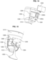
- FIG. 14 is a schematic rear view of a dispenser with a rear cover removed in accordance with an embodiment of the current invention.
- under the dispenser includes adjustment controls 1292a and 1292b (e.g., a toggle button) for determining a maximum and/or minimum opening value for a valve.
- controls could include a switch and/or a dial.
- adjustments may be made using a remote device, for example, over a wireless connection (e.g., Bluetooth) and/or over a network connection.
- the dispenser will include a battery 1294.
- the battery 1294 may be used to hold a valve in a closed when there is a power outage.
- the controls 1292a 1292b may be covered, for example, by rear cover 1263.
- FIG. 15 is a schematic rear view of a dispenser with a rear cover, rear portion of the casing and battery removed in accordance with an embodiment of the current invention.
- a dispenser includes a controller 1248.
- the controller 1248 may be embodied on a printed circuit board (PCB).
- the PCB includes a valve angle indicator 1296 and/or sensors 1298, for example, for sensing the angle of the valve wings (for example wings of valve 416).
- Controller 1248 optionally includes wireless and/or network communication hardware and/or software and/or a code reader (e.g., barcode and/or QR code). Controller 1248 is optionally programmable for various dispensing programs.
- FIG. 16 illustrates a dispenser having a large receptacle in accordance with an embodiment of the current invention.
- a receptacle 1642 supplying dry goods 1641 to a valve assembly 1601 may extend beyond an adapter 1613 and/or the valve assembly 1601. for example, the receptacle 1642 may be supported by a base 1699 separate from the valve assembly 1601.
- the receptacle may have a large capacity (e.g., between 2 to 5 liters and/or between 10 to 20 liters and/or between 20 to 50 liters.
- the receptacle may include a fiduciary marker 1666 (e.g., to indicate the volume of good 1641 in the receptacle.
- the dispenser may be configured (e.g., via programming of a controller) to receive data on how much goods 1641 are placed into the receptacle and/or how much remains and/or how much is dispensed.
- the dispenser will signal when the receptacle needs to be refilled.
- a receptacle includes an exhibition area 1698 for example, to display the product regardless of how much is left in the receptacle.
- the exhibition area may an area for storing good 1641 that does not empty to the valve 1601.
- FIG. 17 illustrates a front perspective view of a dispenser having a large receptacle in accordance with an embodiment of the current invention.
- the receptacle 1642 may include an extended 1743 section that extends outward to the sides beyond the valve assembly 1601.
- the bottom of the extended section 1743 may be inclined towards the valve assembly 1601 for example to funnel the contents of the receptacle 1642 towards the valve assembly 1601.
Landscapes
- Engineering & Computer Science (AREA)
- Physics & Mathematics (AREA)
- Food Science & Technology (AREA)
- General Physics & Mathematics (AREA)
- Toxicology (AREA)
- General Health & Medical Sciences (AREA)
- Artificial Intelligence (AREA)
- Computer Vision & Pattern Recognition (AREA)
- Electromagnetism (AREA)
- Theoretical Computer Science (AREA)
- Health & Medical Sciences (AREA)
- Mechanical Engineering (AREA)
- Life Sciences & Earth Sciences (AREA)
- Biophysics (AREA)
- Fluid Mechanics (AREA)
- Vending Machines For Individual Products (AREA)
- Dairy Products (AREA)
- Confectionery (AREA)
- Devices For Dispensing Beverages (AREA)
Claims (14)
- System zur Ausgabe von Trockenware, umfassend:einen Behälter (742) für die Trockenware;eine Ausgabetülle (742) zur Ausgabe der Trockenware durch Schwerkraftfluss aus dem Behälter;ein Ventil (716) zwischen dem Behälter und der Ausgabetülle, das den Fluss der Trockenwaren aus dem Behälter steuert;wobei das Ventil (416) Klappen umfasst, die in eine geschlossene Position vorgespannt sind, in der sie den freien Fluss der Trockenware aus dem Behälter blockieren;ein Stellglied (744), das die Klappen dreht;eine Steuerung (748), die konfiguriert ist, um dem Stellglied zu befehlen, das Ventil durch Drehen der Klappen gemäß einem Programm zu öffnen und zu schließen, und ferner konfiguriert ist, um dem Stellglied zu befehlen, das Ventil zwischen einer maximalen Öffnungsposition und einer minimalen Öffnungsposition oszillieren zu lassen; undeinen Aktivator (752) für die Steuerung;eine Anpassungsschnittstelle (768) zum Anpassen der maximalen Öffnungsposition.
- System nach Anspruch 1, bei dem die Anpassungsschnittstelle ferner zum Anpassen des Programms konfiguriert ist.
- System nach Anspruch 2, bei dem die Anpassungsschnittstelle (768) einen drahtlosen Empfänger umfasst.
- System nach Anspruch 2, bei dem die Anpassungsschnittstelle (768) einen manuellen Regler zum Anpassen einer Schwingungsrate zwischen der maximalen Öffnungsposition und der minimalen Öffnungsposition und/oder einer Öffnungszeit umfasst.
- System nach Anspruch 2, bei dem die Anpassungsschnittstelle (768) eine Schnittstelle, die zum Eingeben von Eigenschaften der Trockenware konfiguriert ist, und einen Algorithmus zum Bestimmen eines Programms zum Verteilen der Trockenware umfasst.
- System nach Anspruch 5, bei dem die zur Eingabe von Eigenschaften konfigurierte Schnittstelle (768) eine Kamera zum Aufnehmen eines Bildes der Trockenware umfasst.
- System nach Anspruch 6, bei dem die Schnittstelle (768) eine Bildverarbeitungskomponente zum Bestimmen einer Form und Größe der Trockenware aus dem Bild umfasst.
- System nach Anspruch 6, bei dem der Behälter (742) eine Eichmarke aufweist.
- System nach Anspruch 1, das ferner einen manuellen Hebel (1252) zum manuellen Aktivieren der Ausgabe umfasst.
- System nach Anspruch 1, das ferner einen optischen Leser (768) zum Lesen eines das Programm spezifizierenden Codes umfasst.
- Verfahren zum Ausgeben von Trockenware mit den Schritten:Versorgen eines Trockenwaren-Automaten mit einem Behälter (342, 742) für die Trockenware, einer Steuerung (348, 748), einem Hygienebetätiger (352), einer Tülle (312, 712), durch die die Trockenware hindurchgeht, einem Ventil (416, 716) mit Klappen (116a, 116b), die in eine geschlossene Position vorgespannt sind, in der sie den freien Fluss der Trockenware zwischen dem Behälter und der Tülle blockieren, und einem Motor, der auf die Steuerung anspricht und das Ventil antreibt;Platzieren eines Behälters unter der Tülle;Aktivieren des Motors durch den Hygienebetätiger (352) über die Steuerung;Antreiben des Ventils mit dem Motor, um den Durchgang der Trockenware durch die Tülle in den Behälter zu ermöglichen, wobei das Antreiben eine oszillierende Drehung der Flügel zwischen einer maximalen Öffnungsposition und einer minimalen Öffnungsposition umfasst; undAnpassen der maximalen Öffnungsposition.
- Verfahren nach Anspruch 11, das ferner das Einstellen einer Rate der Oszillation umfasst, um ein Zerdrücken der Trockenware zu vermeiden.
- Verfahren nach Anspruch 11, bei dem das Antreiben gemäß einem Programm erfolgt, und das ferner das Lesen des Programms aus einem visuellen Code umfasst.
- Verfahren nach Anspruch 11, bei dem das Antreiben gemäß einem Programm erfolgt, und das Programm konfiguriert ist, um eine vordefinierte Menge der Trockenware abzugeben.
Applications Claiming Priority (1)
| Application Number | Priority Date | Filing Date | Title |
|---|---|---|---|
| US202063122498P | 2020-12-08 | 2020-12-08 |
Publications (3)
| Publication Number | Publication Date |
|---|---|
| EP4011246A1 EP4011246A1 (de) | 2022-06-15 |
| EP4011246B1 true EP4011246B1 (de) | 2024-10-23 |
| EP4011246C0 EP4011246C0 (de) | 2024-10-23 |
Family
ID=78789890
Family Applications (1)
| Application Number | Title | Priority Date | Filing Date |
|---|---|---|---|
| EP21210548.0A Active EP4011246B1 (de) | 2020-12-08 | 2021-11-25 | System zur ausgabe von trockenwaren und verfahren zur ausgabe von trockenwaren |
Country Status (3)
| Country | Link |
|---|---|
| US (1) | US12367731B2 (de) |
| EP (1) | EP4011246B1 (de) |
| IL (1) | IL288363A (de) |
Families Citing this family (4)
| Publication number | Priority date | Publication date | Assignee | Title |
|---|---|---|---|---|
| USD1080311S1 (en) * | 2021-09-30 | 2025-06-24 | Ofer Landau | Electric food dispenser |
| CA3185544A1 (en) * | 2021-12-22 | 2023-06-22 | Mindful Snacks Inc. | Systems, methods and apparatus for touchless dispensing |
| USD1034106S1 (en) * | 2022-03-29 | 2024-07-09 | Spemot Ag | Knife holder for electric kitchen appliances |
| FR3146883A1 (fr) * | 2023-03-22 | 2024-09-27 | Groupement D'interet Ecosystemik | Mécanisme distributeur de produit alimentaire et ensemble comportant un tel mécanisme |
Family Cites Families (15)
| Publication number | Priority date | Publication date | Assignee | Title |
|---|---|---|---|---|
| BR9204762A (pt) * | 1991-01-29 | 1993-07-06 | Buehler Ag | Processo para o provimento de peso exato de quantidades de enchimento predefinidas de produtos a granel,bem como equipamento de enchimento |
| US5230300A (en) * | 1992-07-20 | 1993-07-27 | Victor Mezhinsky | Automatic dry food feeder for animals |
| US5738153A (en) * | 1995-11-03 | 1998-04-14 | E. I. Du Pont De Nemours And Company | Measuring and dispensing system for solid dry flowable materials |
| US5947336A (en) | 1997-04-01 | 1999-09-07 | Thompson; Patrick | Dry food dispenser |
| IL134860A0 (en) * | 2000-03-02 | 2001-05-20 | Gal Michael | Electronically controlled animal food dispenser |
| NL1019092C2 (nl) | 2001-10-03 | 2003-04-07 | Lely Entpr Ag | Samenstel voor het automatisch in een bepaalde periode afgeven van een hoeveelheid voeder aan een melkdier. |
| AUPR963701A0 (en) * | 2001-12-20 | 2002-01-24 | Springett, Alan | Automatic animal food dispenser |
| US7878376B2 (en) | 2007-02-08 | 2011-02-01 | Golden Gt Llc | Dry goods dispenser and dispensing mechanism |
| MX2010006273A (es) * | 2007-12-10 | 2010-06-23 | Du Pont | Sistema dosificador de multiples productos para materiales granulares. |
| US20110062190A1 (en) | 2009-09-11 | 2011-03-17 | Trade Fixtures, Llc | Bulk product dispenser having a container-activated dispensing actuator release assembly |
| US20140131384A1 (en) | 2012-11-12 | 2014-05-15 | Jose L MARTINEZ | Personal Cereal Dispenser |
| CA2973161C (en) | 2013-08-29 | 2020-07-07 | Tastetro Inc. | Automated dispenser and method for dispensing |
| US9549640B2 (en) * | 2014-06-16 | 2017-01-24 | Ofer Landau | Free flow control dispenser device and method |
| US10665051B2 (en) | 2017-02-02 | 2020-05-26 | Smartbins Inc. | Bulk food integrated scale system |
| CN111528716A (zh) | 2020-06-30 | 2020-08-14 | 江西蓑衣佬农农业开发有限公司 | 一种可定量出米的储米桶 |
-
2021
- 2021-11-23 US US17/533,140 patent/US12367731B2/en active Active
- 2021-11-24 IL IL288363A patent/IL288363A/en unknown
- 2021-11-25 EP EP21210548.0A patent/EP4011246B1/de active Active
Also Published As
| Publication number | Publication date |
|---|---|
| IL288363A (en) | 2022-07-01 |
| EP4011246C0 (de) | 2024-10-23 |
| US12367731B2 (en) | 2025-07-22 |
| US20220180690A1 (en) | 2022-06-09 |
| EP4011246A1 (de) | 2022-06-15 |
Similar Documents
| Publication | Publication Date | Title |
|---|---|---|
| EP4011246B1 (de) | System zur ausgabe von trockenwaren und verfahren zur ausgabe von trockenwaren | |
| JP6912444B2 (ja) | 測定量の、ばらけた材料を分配するためのシステムおよび方法 | |
| US4789106A (en) | Combined coffee bean weigher and grinder with selectable measured quantities | |
| JP5837513B2 (ja) | コーヒー飲料システム、このシステムで使うためのコーヒー豆包装カートリッジ、飲料を調製する方法、コーヒーを抽出するための方法、コーヒー豆を供給するための方法、コーヒー豆材料のためのカートリッジ、コーヒー豆材料を供給する方法 | |
| US7874505B1 (en) | Food grinder with electronically adjustable grind settings, tooless disassembly | |
| US20210000069A1 (en) | Feeder | |
| US10165898B2 (en) | Coffee bean conveyance device | |
| US20080110935A1 (en) | Baby formula preparation device | |
| US5244020A (en) | Dispenser | |
| US20060249531A1 (en) | Motion Activated Food Dispenser | |
| US4790457A (en) | Sanitary foodstuff dispenser with baffle | |
| US20090127363A1 (en) | Automatic dosage unit | |
| US7464888B2 (en) | Automatic dosage unit | |
| CN108573570B (zh) | 自动售货机及自动售货系统 | |
| US20240410733A1 (en) | Vibratory bean doser | |
| US2967644A (en) | Dispensing machine | |
| CN108109271B (zh) | 一种现碾不同精度鲜米的智能售米机及其售米方法 | |
| EP1174065A1 (de) | Gerät zum Mahlen und Abgeben von Kaffee | |
| JPH11118584A (ja) | 米穀用の計量袋詰め機 | |
| GB2526156A (en) | A dispensing system and method | |
| HK1188915B (en) | System and method for dispensing a measured amount of a loose material |
Legal Events
| Date | Code | Title | Description |
|---|---|---|---|
| PUAI | Public reference made under article 153(3) epc to a published international application that has entered the european phase |
Free format text: ORIGINAL CODE: 0009012 |
|
| STAA | Information on the status of an ep patent application or granted ep patent |
Free format text: STATUS: THE APPLICATION HAS BEEN PUBLISHED |
|
| AK | Designated contracting states |
Kind code of ref document: A1 Designated state(s): AL AT BE BG CH CY CZ DE DK EE ES FI FR GB GR HR HU IE IS IT LI LT LU LV MC MK MT NL NO PL PT RO RS SE SI SK SM TR |
|
| STAA | Information on the status of an ep patent application or granted ep patent |
Free format text: STATUS: REQUEST FOR EXAMINATION WAS MADE |
|
| 17P | Request for examination filed |
Effective date: 20221117 |
|
| RBV | Designated contracting states (corrected) |
Designated state(s): AL AT BE BG CH CY CZ DE DK EE ES FI FR GB GR HR HU IE IS IT LI LT LU LV MC MK MT NL NO PL PT RO RS SE SI SK SM TR |
|
| STAA | Information on the status of an ep patent application or granted ep patent |
Free format text: STATUS: EXAMINATION IS IN PROGRESS |
|
| 17Q | First examination report despatched |
Effective date: 20230725 |
|
| GRAP | Despatch of communication of intention to grant a patent |
Free format text: ORIGINAL CODE: EPIDOSNIGR1 |
|
| STAA | Information on the status of an ep patent application or granted ep patent |
Free format text: STATUS: GRANT OF PATENT IS INTENDED |
|
| INTG | Intention to grant announced |
Effective date: 20240613 |
|
| GRAS | Grant fee paid |
Free format text: ORIGINAL CODE: EPIDOSNIGR3 |
|
| GRAA | (expected) grant |
Free format text: ORIGINAL CODE: 0009210 |
|
| STAA | Information on the status of an ep patent application or granted ep patent |
Free format text: STATUS: THE PATENT HAS BEEN GRANTED |
|
| AK | Designated contracting states |
Kind code of ref document: B1 Designated state(s): AL AT BE BG CH CY CZ DE DK EE ES FI FR GB GR HR HU IE IS IT LI LT LU LV MC MK MT NL NO PL PT RO RS SE SI SK SM TR |
|
| REG | Reference to a national code |
Ref country code: GB Ref legal event code: FG4D |
|
| REG | Reference to a national code |
Ref country code: CH Ref legal event code: EP |
|
| REG | Reference to a national code |
Ref country code: DE Ref legal event code: R096 Ref document number: 602021020598 Country of ref document: DE |
|
| REG | Reference to a national code |
Ref country code: IE Ref legal event code: FG4D |
|
| U01 | Request for unitary effect filed |
Effective date: 20241113 |
|
| U07 | Unitary effect registered |
Designated state(s): AT BE BG DE DK EE FI FR IT LT LU LV MT NL PT RO SE SI Effective date: 20241120 |
|
| U20 | Renewal fee for the european patent with unitary effect paid |
Year of fee payment: 4 Effective date: 20250217 |
|
| PG25 | Lapsed in a contracting state [announced via postgrant information from national office to epo] |
Ref country code: HR Free format text: LAPSE BECAUSE OF FAILURE TO SUBMIT A TRANSLATION OF THE DESCRIPTION OR TO PAY THE FEE WITHIN THE PRESCRIBED TIME-LIMIT Effective date: 20241023 Ref country code: IS Free format text: LAPSE BECAUSE OF FAILURE TO SUBMIT A TRANSLATION OF THE DESCRIPTION OR TO PAY THE FEE WITHIN THE PRESCRIBED TIME-LIMIT Effective date: 20250223 |
|
| PG25 | Lapsed in a contracting state [announced via postgrant information from national office to epo] |
Ref country code: ES Free format text: LAPSE BECAUSE OF FAILURE TO SUBMIT A TRANSLATION OF THE DESCRIPTION OR TO PAY THE FEE WITHIN THE PRESCRIBED TIME-LIMIT Effective date: 20241023 |
|
| PG25 | Lapsed in a contracting state [announced via postgrant information from national office to epo] |
Ref country code: NO Free format text: LAPSE BECAUSE OF FAILURE TO SUBMIT A TRANSLATION OF THE DESCRIPTION OR TO PAY THE FEE WITHIN THE PRESCRIBED TIME-LIMIT Effective date: 20250123 |
|
| PG25 | Lapsed in a contracting state [announced via postgrant information from national office to epo] |
Ref country code: GR Free format text: LAPSE BECAUSE OF FAILURE TO SUBMIT A TRANSLATION OF THE DESCRIPTION OR TO PAY THE FEE WITHIN THE PRESCRIBED TIME-LIMIT Effective date: 20250124 |
|
| PG25 | Lapsed in a contracting state [announced via postgrant information from national office to epo] |
Ref country code: PL Free format text: LAPSE BECAUSE OF FAILURE TO SUBMIT A TRANSLATION OF THE DESCRIPTION OR TO PAY THE FEE WITHIN THE PRESCRIBED TIME-LIMIT Effective date: 20241023 |
|
| PG25 | Lapsed in a contracting state [announced via postgrant information from national office to epo] |
Ref country code: RS Free format text: LAPSE BECAUSE OF FAILURE TO SUBMIT A TRANSLATION OF THE DESCRIPTION OR TO PAY THE FEE WITHIN THE PRESCRIBED TIME-LIMIT Effective date: 20250123 |
|
| U1N | Appointed representative for the unitary patent procedure changed after the registration of the unitary effect |
Representative=s name: METIDA; LT |
|
| REG | Reference to a national code |
Ref country code: CH Ref legal event code: PL |
|
| PG25 | Lapsed in a contracting state [announced via postgrant information from national office to epo] |
Ref country code: SM Free format text: LAPSE BECAUSE OF FAILURE TO SUBMIT A TRANSLATION OF THE DESCRIPTION OR TO PAY THE FEE WITHIN THE PRESCRIBED TIME-LIMIT Effective date: 20241023 |
|
| PG25 | Lapsed in a contracting state [announced via postgrant information from national office to epo] |
Ref country code: MC Free format text: LAPSE BECAUSE OF FAILURE TO SUBMIT A TRANSLATION OF THE DESCRIPTION OR TO PAY THE FEE WITHIN THE PRESCRIBED TIME-LIMIT Effective date: 20241023 |
|
| REG | Reference to a national code |
Ref country code: CH Ref legal event code: PL |
|
| PG25 | Lapsed in a contracting state [announced via postgrant information from national office to epo] |
Ref country code: CH Free format text: LAPSE BECAUSE OF NON-PAYMENT OF DUE FEES Effective date: 20241130 |
|
| PG25 | Lapsed in a contracting state [announced via postgrant information from national office to epo] |
Ref country code: SK Free format text: LAPSE BECAUSE OF FAILURE TO SUBMIT A TRANSLATION OF THE DESCRIPTION OR TO PAY THE FEE WITHIN THE PRESCRIBED TIME-LIMIT Effective date: 20241023 |
|
| PG25 | Lapsed in a contracting state [announced via postgrant information from national office to epo] |
Ref country code: CZ Free format text: LAPSE BECAUSE OF FAILURE TO SUBMIT A TRANSLATION OF THE DESCRIPTION OR TO PAY THE FEE WITHIN THE PRESCRIBED TIME-LIMIT Effective date: 20241023 |
|
| PLBE | No opposition filed within time limit |
Free format text: ORIGINAL CODE: 0009261 |
|
| STAA | Information on the status of an ep patent application or granted ep patent |
Free format text: STATUS: NO OPPOSITION FILED WITHIN TIME LIMIT |
|
| 26N | No opposition filed |
Effective date: 20250724 |
|
| PG25 | Lapsed in a contracting state [announced via postgrant information from national office to epo] |
Ref country code: IE Free format text: LAPSE BECAUSE OF NON-PAYMENT OF DUE FEES Effective date: 20241125 |
|
| U20 | Renewal fee for the european patent with unitary effect paid |
Year of fee payment: 5 Effective date: 20251117 |
|
| PGFP | Annual fee paid to national office [announced via postgrant information from national office to epo] |
Ref country code: GB Payment date: 20251117 Year of fee payment: 5 |