EP4010897B1 - Aktive geräuschverminderung bei direktionalen akustischen offenohr-vorrichtungen - Google Patents
Aktive geräuschverminderung bei direktionalen akustischen offenohr-vorrichtungen Download PDFInfo
- Publication number
- EP4010897B1 EP4010897B1 EP20757497.1A EP20757497A EP4010897B1 EP 4010897 B1 EP4010897 B1 EP 4010897B1 EP 20757497 A EP20757497 A EP 20757497A EP 4010897 B1 EP4010897 B1 EP 4010897B1
- Authority
- EP
- European Patent Office
- Prior art keywords
- acoustic
- audio
- microphone
- transducer
- user
- Prior art date
- Legal status (The legal status is an assumption and is not a legal conclusion. Google has not performed a legal analysis and makes no representation as to the accuracy of the status listed.)
- Active
Links
Images


Classifications
-
- G—PHYSICS
- G10—MUSICAL INSTRUMENTS; ACOUSTICS
- G10K—SOUND-PRODUCING DEVICES; METHODS OR DEVICES FOR PROTECTING AGAINST, OR FOR DAMPING, NOISE OR OTHER ACOUSTIC WAVES IN GENERAL; ACOUSTICS NOT OTHERWISE PROVIDED FOR
- G10K11/00—Methods or devices for transmitting, conducting or directing sound in general; Methods or devices for protecting against, or for damping, noise or other acoustic waves in general
- G10K11/16—Methods or devices for protecting against, or for damping, noise or other acoustic waves in general
- G10K11/175—Methods or devices for protecting against, or for damping, noise or other acoustic waves in general using interference effects; Masking sound
- G10K11/178—Methods or devices for protecting against, or for damping, noise or other acoustic waves in general using interference effects; Masking sound by electro-acoustically regenerating the original acoustic waves in anti-phase
-
- H—ELECTRICITY
- H04—ELECTRIC COMMUNICATION TECHNIQUE
- H04R—LOUDSPEAKERS, MICROPHONES, GRAMOPHONE PICK-UPS OR LIKE ACOUSTIC ELECTROMECHANICAL TRANSDUCERS; ELECTRIC HEARING AIDS; PUBLIC ADDRESS SYSTEMS
- H04R1/00—Details of transducers, loudspeakers or microphones
- H04R1/10—Earpieces; Attachments therefor ; Earphones; Monophonic headphones
- H04R1/105—Earpiece supports, e.g. ear hooks
-
- H—ELECTRICITY
- H04—ELECTRIC COMMUNICATION TECHNIQUE
- H04R—LOUDSPEAKERS, MICROPHONES, GRAMOPHONE PICK-UPS OR LIKE ACOUSTIC ELECTROMECHANICAL TRANSDUCERS; ELECTRIC HEARING AIDS; PUBLIC ADDRESS SYSTEMS
- H04R1/00—Details of transducers, loudspeakers or microphones
- H04R1/10—Earpieces; Attachments therefor ; Earphones; Monophonic headphones
- H04R1/1083—Reduction of ambient noise
-
- G—PHYSICS
- G10—MUSICAL INSTRUMENTS; ACOUSTICS
- G10K—SOUND-PRODUCING DEVICES; METHODS OR DEVICES FOR PROTECTING AGAINST, OR FOR DAMPING, NOISE OR OTHER ACOUSTIC WAVES IN GENERAL; ACOUSTICS NOT OTHERWISE PROVIDED FOR
- G10K2210/00—Details of active noise control [ANC] covered by G10K11/178 but not provided for in any of its subgroups
- G10K2210/10—Applications
- G10K2210/108—Communication systems, e.g. where useful sound is kept and noise is cancelled
- G10K2210/1081—Earphones, e.g. for telephones, ear protectors or headsets
-
- H—ELECTRICITY
- H04—ELECTRIC COMMUNICATION TECHNIQUE
- H04R—LOUDSPEAKERS, MICROPHONES, GRAMOPHONE PICK-UPS OR LIKE ACOUSTIC ELECTROMECHANICAL TRANSDUCERS; ELECTRIC HEARING AIDS; PUBLIC ADDRESS SYSTEMS
- H04R2460/00—Details of hearing devices, i.e. of ear- or headphones covered by H04R1/10 or H04R5/033 but not provided for in any of their subgroups, or of hearing aids covered by H04R25/00 but not provided for in any of its subgroups
- H04R2460/01—Hearing devices using active noise cancellation
Definitions
- This disclosure generally relates to wearable open-ear acoustic devices.
- Wearable audio devices such as off-ear headphones, produce sound using an electro-acoustic transducer that is spaced from the user's ear canal entrance. These wearable audio devices may take various form factors. In some cases, these wearable audio devices include audio eyeglasses configured to rest on the ears and nose of the user. The audio eyeglasses can include transducers proximate one or both of the user's ears, e.g., located on the arms of the eyeglasses.
- the present invention relates to an open ear acoustic device according to claim 1.
- Advantageous embodiments are set forth in dependent claims of the appended claim set.
- this document features an acoustic device that includes at least one acoustic transducer disposed such that, in a head-worn state, the at least one acoustic transducer is in an open-ear configuration in which an ear canal of a user of the acoustic device is unobstructed.
- the acoustic device also includes an array of two or more first microphones that captures audio preferentially from a first direction as compared to at least a second direction different from the first direction, wherein the audio captured using the array is processed and played back through the at least one acoustic transducer, and an active noise reduction (ANR) engine that includes one or more processing devices.
- the ANR engine is configured to generate a driver signal for the at least one acoustic transducer, the driver signal having phases that reduce effects of audio captured from at least the second direction.
- this document features a set of wearable audio eyeglasses that includes a frame, at least one acoustic transducer, an array of two or more first microphones, and an electronics module.
- the frame includes a frontal region that includes a pair of lens receptacles, and a bridge disposed between the lens receptacles.
- the frame also includes a pair of arms extending from the frontal region of the frame.
- the at least one acoustic transducer is configured to direct audio output towards an ear of a user in a head-worn state of the audio eyeglasses.
- the array of two or more first microphones captures audio preferentially from a first direction as compared to at least a second direction different from the first direction.
- the electronics module includes an amplifier circuit that receives the audio captured using the array, and generates a first driver signal for the at least one acoustic transducer based on the audio.
- the electronics module also includes an active noise reduction (ANR) engine comprising one or more processing devices, wherein the ANR engine generates a second driver signal for the at least one acoustic transducer, the second driver signal having phases that reduce effects of audio captured from at least the second direction.
- ANR active noise reduction
- the ANR engine can be configured to reduce the effects of the audio captured from the second direction in a 300-1500 Hz frequency band.
- the ANR engine can be configured to increase a power ratio of (i) audio signals in the 300-1500 Hz frequency band, as captured from the first direction and (ii) audio signals in the 300-1500 Hz frequency band, as captured from at least the second direction, by at least 5 dB.
- the acoustic device can include at least a second microphone to capture audio from the second direction. In the head-worn state, the second microphone can be located behind a pinna of the user.
- the acoustic device can include an amplifier circuit configured to process the audio captured using the array.
- the magnitude and phase of a sound pressure response from the at least one acoustic transducer to a microphone can be substantially similar to a sound pressure response from the at least one acoustic transducer to a location of an ear canal.
- a mainlobe of a radiation pattern of the at least one acoustic transducer can be directed towards the ear canal of the user, and a power ratio of (i) a portion of output of the at least one acoustic transducer radiated towards the ear canal of the user and (ii) a portion of output of the at least one acoustic transducer radiated towards a microphone of the array can be at least 10 dB.
- the ANR engine can include an analog to digital converter, an amplifier, compensator, and a digital to analog converter.
- An array of microphones disposed in an open-ear device can facilitate directional capture, for example, to amplify audio coming from a particular direction (e.g., look/gaze direction of the user).
- One or more acoustic transducers can facilitate delivery of audio to user's ears without significant coupling to the microphones.
- one or more of the microphones can be disposed at locations substantially close to the ears such that signals detected by such microphone(s) can be used as a reference for an echo canceler. Use of such echo cancelers can potentially improve the quality of audio delivered to the user's ears thereby improving the user experience.
- the open-ear devices can also include a feedforward and/or feedback active noise reduction (ANR) signal paths that can be configured to improve a signal to noise ratio (SNR) from a particular direction (e.g., look/gaze direction of the user) by at least 5 dB.
- ANR active noise reduction
- SNR signal to noise ratio
- Such improvement over a particular portion of the spectrum e.g., a portion of the speech band
- the noise reduction (possibly in combination with the directional capture/amplification) in turn can improve the feasibility of using open-ear devices not only as hearing aids, but also generally as hearing assistance devices that improve speech intelligibility for users who do not have hearing loss.
- the technology described herein can potentially improve the acoustic performances of open-ear audio devices such as audio eyeglasses or head-mounted acoustic devices.
- the improvements in directional capture, SNR, and/or reduction in coupling between microphones and acoustic transducers can facilitate the use of open ear devices such as hearing aids.
- Such open-ear form factors can make hearing aids more acceptable (e.g., from a social use standpoint) to some users, particularly ones who are hesitant to use them otherwise.
- This document describes technology for facilitating capture of audio signals in open-ear acoustic devices, and delivering the captured (and amplified) audio to user's ears such that the coupling between microphones and acoustic transducers is not significant, and the output of the acoustic transducers is low enough to not reach other people in the vicinity of the user.
- this document also describes feedforward and feedback noise reduction processes that allow for reducing the effect of audio coming from directions outside of one or more target directions. Such noise reduction, particularly in portions of the speech band, can result in at least 5 dB of improvement in signal to noise ratio (SNR), which in turn can improve speech perception/intelligibility even for users who do not have hearing loss.
- SNR signal to noise ratio
- the technology described herein can allow a user to select the target direction from which audio is to be emphasized.
- the target direction can be the direction at which a user is looking-referred to herein as the look direction or gaze direction of the user.
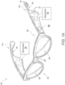
- FIG. 1A shows a schematic depiction of a pair or set of wearable audio eyeglasses 10 as an example of an open-ear acoustic device.
- the audio eyeglasses 10 can include a frame 20 having a frontal region 30 and a pair of arms (also referred to as temples) 40a and 40b (40, in general) extending from the frontal region 30.
- the frontal region 30 and arms 40 are designed for resting on the head of a user.
- the frontal region 30 can include a set of lenses 50 fitted to corresponding lens receptacles.
- the two lens receptacles are connected by a bridge 60 (which may include padding) for resting on the user's nose in a head-worn state of the audio eyeglasses.
- the lenses can include prescription, non--prescription and/or light-filtering lenses.
- Arms 40 can include a contour 65 for resting on the user's respective ears.
- the frame 20 includes electronics module 70 and other components for controlling the audio eyeglasses 10 according to particular implementations.
- electronics module 70 and other components for controlling the audio eyeglasses 10 according to particular implementations.
- separate, or duplicate sets of electronics module 70 are included in portions of the frame, e.g., each of the respective arms 40 in the frame 20.
- certain components described herein can also be present in singular form.
- the electronics module 70 is disposed in the arms 40 of the frame 20, in some implementations, at least portions of the electronics module 70 may be disposed elsewhere in the frame (e.g., in a portion of the frontal region 30 such as the bridge 60).
- FIG. 1B is a schematic depiction of the electronics module 70 included in the audio eyeglasses of FIG. 1A .
- the components in electronics module 70 may be implemented as hardware and/or software, and such components may be connected to one another by hard-wired and/or wireless connections.
- the components described as connected or coupled to other components in audio eyeglasses 10 or other systems may communicate over hard-wired connections and/or using communications protocols.
- the electronics module 70 includes a transceiver 72 and an antenna 74 that facilitates wireless communication with another electronics module and/or other wireless-enabled devices such as a mobile phone, tablet, or smartwatch.
- the communications protocol(s) used by the electronics module 70 in communicating with one another can include, for example, a Wi-Fi protocol using a wireless local area network (LAN), a communication protocol such as IEEE 802.11 b/g, a cellular network-based protocol (e.g., third, fourth or fifth generation (3G, 4G, 5G cellular networks) or one of a plurality of internet-of-things (loT) protocols, such as: Bluetooth, BLE Bluetooth, ZigBee (mesh LAN), Z-wave (sub-GHz mesh network), 6LoWPAN (a lightweight IP protocol), LTE protocols, RFID, ultrasonic audio protocols, etc.
- LAN wireless local area network
- a communication protocol such as IEEE 802.11 b/g
- a cellular network-based protocol e.g., third, fourth or fifth generation (3G, 4G, 5G cellular networks
- LoT internet-of-things
- the electronics module 70 includes one or more electroacoustic transducers 80 disposed such that, in a head-worn state of the corresponding device, the one or more electroacoustic transducers 80 are in an open-ear configuration.
- an acoustic transducer 80 can be disposed on an arm 40 of the audio eyeglasses 10, such that the transducer 80 does not cover the ear canal of the user.
- At least two electroacoustic transducers 80 are positioned proximate to (but physically separated from) the ears of the user (e.g., one transducer 80 proximate to each ear.
- the one or more transducers 80 can be disposed to extend from the arms 40 such that they (or their respective housings or structures for interfacing with the ear) physically contact at least a portion of the ears of the user while not occluding the ear canals from the environment.
- the audio eyeglasses 10 of FIG. 1A are shown as an example of a head-worn open-ear acoustic device, other types of open-ear devices are also within the scope of this disclosure.
- the technology described herein can be used in open-ear headphones or other head-worn acoustic devices, examples of which are shown in U.S. Patent 9,794,676 , and U.S. Patent 9,794,677 .
- each transducer 80 can be used as a dipole loudspeaker with an acoustic driver or radiator that emits front-side acoustic radiation from its front side, and emits rear-side acoustic radiation from its rear side.
- the dipole loudspeaker can be built into the frame 20 of the audio eyeglasses 10.
- an acoustic channel defined within the housing of the eyeglasses 10 e.g. within the arms 40
- can direct the front-side acoustic radiation and another acoustic channel can direct the rear-side acoustic radiation.
- a plurality of sound-conducting vents (openings) in the housing allow sound to leave the housing.
- Openings in the eyeglass frame 20 can be aligned with these vents, so that the sound also leaves the frame 20.
- the distance between the sound-conducting openings defines an effective length of an acoustic dipole of the loudspeaker.
- the effective length may be considered to be the distance between the two openings that contribute most to the emitted radiation at any particular frequency.
- the housing and its openings can be constructed and arranged such that the effective dipole length is frequency dependent.
- the transducer 80 e.g., loudspeaker dipole transducer
- Exemplary dipole transducers are shown and described in U.S. patent application serial nos. 16/151,541, filed October 4, 2018 ; and 16/408,179, filed May 9, 2019 .
- the electronic module 70 includes an amplifier circuit 86 that processes signals representing the audio captured using the microphones of the array 75, and generates driver signals for the one or more acoustic transducers 80. In some cases, this can be improve the user's perception of speech in noise environments. For example, even a 5-10 dB improvement in the ratio of power from a particular direction to the power from other directions can improve perception of speech, particularly when the improvement is within the speech band (e.g., in the 300-1500 Hz frequency band) of the audio spectrum.
- the speech band e.g., in the 300-1500 Hz frequency band
- the multiple microphones can be disposed in the corresponding device in various ways.
- the one or more microphones of the array 75 may be disposed along an arm or temple 40 of the eyeglass frame 20.
- at least one microphone of the array 75 may be disposed in the frontal region 30 (e.g., on the bridge 60) of the frame 20.
- the microphones of the array 75 can be separate from any microphones that are disposed for the purpose of capturing the voice of the user (e.g., for spoken commands, phone conversations etc.).
- one or more microphones of the array 75 can also be used for capturing the voice of the user.
- the locations of the microphones in the array 75 and the locations of the one or more acoustic transducers 80 can be jointly determined to implement an acoustics package that provides for directional audio delivery and capture in open-ear acoustic devices.
- the locations of the transducers 80 and the microphones in the array 75 can be determined such that the transducers 80 satisfactorily deliver audio towards the ear of the user, without directing audio towards a microphone over a target or threshold amount.
- the one or more acoustic transducers 80 and the multiple microphones of the array 75 can be disposed on a head-worn acoustic device (e.g., the audio eyeglasses 10) such that, in the head-worn state, a mainlobe of a radiation pattern of a directional acoustic transducer is directed towards the ear canal of the user, while a power ratio of (i) a portion of output of the one or more acoustic transducers radiated towards the ear canal of the user and (ii) a portion of output of the at least one acoustic transducer radiated towards a microphone of the array 75 satisfies a threshold condition.
- a head-worn acoustic device e.g., the audio eyeglasses 10.
- a threshold condition can dictate that the above-referenced power ratio is at least 10 dB.
- the locations of the transducers 80 and the microphones of the array 75 can be determined while accounting for the directionality of the transducers, and/or the microphones, and/or the corresponding arrays.
- the locations of the microphones of the array 75 are determined first, and the locations of the acoustic transducers 80 are then determined to achieve the target performances discussed above. For example, once the locations associated with the microphone array 75 are determined, the locations of the one or more acoustic transducers 80 are then determined such that the transducers 80 satisfactorily deliver audio towards the ear of the user, without directing audio towards a microphone of the array 75 over the target or threshold amount.
- the microphone(s) may be located in or near an acoustic null in a radiation pattern of the dipole transducer. In some cases, the microphone is positioned in a region in which acoustic energy radiated from a first radiating surface of the transducer destructively interferes with acoustic energy radiated from a second radiating surface of the transducer.
- the electronics module 70 includes a controller 82 that coordinates and controls various portions of the electronic module 70.
- the controller 82 can include one or more processing devices that, in communication with one or more non-transitory machine-readable storage devices, execute various operations of the electronic module 70.
- the controller 82 implements an active noise reduction (ANR) engine 84 that generates driver signals for reducing the effect of audio signals that are considered as "noise.”
- ANR active noise reduction
- the audio captured from a particular direction e.g., the gaze direction of a user
- the audio captured from other directions can be considered to be noise.
- the ANR engine 84 can be configured to generate one or more driver signals that have phases that are substantially inverted with respect to the phases of the noise signal, such that the driver signals generated by the ANR engine 84 destructively interferes with the noise signal (based on the principles of superposition) to reduce the effects of the noise.
- the ANR engine 84 can include multiple noise reduction pathways such as a feedback path and a feedforward path (generally referred to as ANR pathways, ANR signal paths) that require the use of microphones to capture corresponding reference signals.
- ANR pathways ANR signal paths
- one or more microphones of the array 75 can be used as a microphone for an ANR signal path, and in such cases, the placement of the corresponding microphones can be governed by whether the microphones are used for capturing reference audio for feedforward path or a feedback path.
- a description of an ANR engine 84 is provided first.
- the signal flow topologies can include a feedback noise reduction path 214 that drives the output transducer 80 to generate an anti-noise signal (using, for example, a feedback compensator 216) to reduce the effects of a noise signal picked up by the feedback microphone 204.
- the signal flow topologies can also include an additional signal processing path 218 that includes circuitry (e.g., an echo canceller 220) for further improving the noise reduction performance of the ANR engine 84.
- the ANR engine 84 can include a configurable digital signal processor (DSP), which can be used for implementing the various signal flow topologies and filter configurations. Examples of such DSPs are described in U.S. Patents 8,073,150 and 8,073,151 .
- An acoustic transducer 80 (e.g., a dipole) can then be placed such that the feedback microphone is located in the null of the dipole. This can be particularly advantageous in some applications, for example, when the audio eyeglasses 10 are being used as hearing aids.
- the feedback microphone may be at a location where the transfer function of an acoustic path between the transducer 80 and the microphone is similar in magnitude and phase to the transfer function of an acoustic path between the transducer and the ear canal. As such, configuring the ANR engine to control sound at the feedback microphone will yield similarly controlled sound at the ear canal, since this microphone location serves as an approximate proxy for the ear canal for sound from both the transducer and the environment.
- a feedforward microphone 202 can be placed, for example, at a location such that the microphone is located behind the pinna of a user in a head-worn state of the device.
- the location 44 at the end of an arm 40 represents a possible location for a feedforward microphone.
- such behind-the-pinna location of the feedforward microphone 202 allows for effective feedforward cancellation of sounds coming from behind the user in a head-word state of the device, which in turn improves the perception of sounds coming from the frontal direction (e.g., that may coincide with the gaze direction of the user).
- the performance of an open ear device can be further improved by implementing an echo canceler (or echo cancellation circuit) that reduces the effects of any output of the transducer 80 as picked by a microphone such as the feedback microphone 204.
- a reference microphone 208 can be used for picking up a different version of a signal that is also picked up or captured by the feedback microphone 204.
- an echo cancellation circuit (K echo ) 220 can generate an additional signal, which, when combined with the output of the feedback compensator 216, further reduces the effect of coupling between the transducer 80 and the microphones. While the echo cancellation circuit shown in the example of FIG.
- the echo cancellation circuit includes a biquad filter that generates a reference signal for the echo cancellation (or feedback cancellation in case of hearing aids).
- the electronics module 70 can also include an inertial measurement unit (IMU) 90, and a power source 100.
- the power source 100 is connected to the transducer 80, and can additionally be connected to the IMU 90.
- Each of the transducer 80, IMU 90 and power source 100 are connected with the controller 82, which is configured to perform control functions according to various implementations described herein.
- the IMU 90 can include a microelectromechanical system (MEMS) device that combines a multi-axis accelerometer, gyroscope, and/or magnetometer.
- MEMS microelectromechanical system
- the power source 100 to the transducer 80 can be provided locally (e.g., with a battery in each of the temple regions of the frame 20), or a single battery can transfer power via wiring that passes through the frame 20 or is otherwise transferred from one temple to the other.
- the power source 100 can be used to control operation of the transducer 80, according to various implementations.
- the controller 82 can include conventional hardware and/or software components for executing program instructions or code according to processes described herein.
- controller 82 may include one or more processing devices, memory, communications pathways between components, and/or one or more logic engines for executing program code.
- Controller 82 can be coupled with other components in the electronics module 70 via any conventional wireless and/or hardwired connection which allows controller 82 to send/receive signals to/from those components and control operation thereof.
- the audio eyeglasses 10 include an interface 95, which is connected with the controller 82.
- the interface 95 can be used for functions such as audio selection, powering on the audio eyeglasses or engaging a voice control function.
- the interface 95 includes a button or a capacitive touch interface.
- the interface 95 includes a compressible interface, which can allow a user to squeeze one or more sections of the audio eyeglasses 10 (e.g., arms 40) to initiate a user interface command.
- the interface 95 can include one or more microphones that are used for capturing spoken commands from the user.
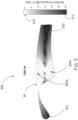
- FIG. 3 is a heat map diagram 300 illustrating an acoustic distribution over a surface of an arm 40 of a pair of audio eyeglasses depicted in FIG. 1A .
- Such an acoustic distribution diagram 300 represents the radiation pattern of the underlying one or more acoustic transducers, and can be used for placements of the one or more microphones in accordance with the technology herein.
- the heat map diagram can vary as a function of frequency, and diagrams for multiple frequencies or frequency ranges may need to be considered for determining optimal locations for acoustic transducers and/or microphones.
- FIG. 3 is a heat map diagram 300 illustrating an acoustic distribution over a surface of an arm 40 of a pair of audio eyeglasses depicted in FIG. 1A .
- Such an acoustic distribution diagram 300 represents the radiation pattern of the underlying one or more acoustic transducers, and can be used for placements of the one or more microphones in accordance with the technology here
- FIG. 3 illustrates the heat map diagram for 1000 Hz audio emanating from a dipole acoustic transducer (also referred to as an acoustic dipole) having two ends at the locations 405a and 405b, respectively.
- the heat map illustrates a distribution of surface pressure at various locations normalized with respect to a surface pressure at the ear. Therefore, the heat map tracks the variation in the ratio of two quantities-(i) G od - amount of coupling between an acoustic transducer and a microphone placed at the corresponding location, and (ii) G ed - amount of coupling between the acoustic transducer and a location of the ear-as a function of locations on the arm 40.
- the one or more microphones can be placed at locations where the ratio is low (or more negative when expressed in dB). Therefore, the shades that are towards the bottom 315 of the heat map legend represent good locations for placement of microphones, and shades that are towards the top 310 of the heat map legend represent locations where a microphone is likely to pick up audio that approximates what is heard at the location of the ear.
- the area 320 represents locations where the ratio is very low (e.g., as expected at acoustic nulls in a radiation pattern of an acoustic transducer such as a dipole), making such locations suitable for placement of one or more microphones.
- one or more feedback microphones 204 may be placed near the ear canal, in order to be coherent with the environmental sound signal at the ear canal. This can be done, for example, by placing the one or more feedback microphones along the heat map contours where the mapped ratio is approximately 0dB, e.g., at the boundary between the lightest gray and white contours. In such cases the audio received from the transducer 80, as picked up by a feedback microphone, approximates the audio reaching the ear canal from the transducer 80.
- a feedforward microphone could capture some amount of the transducer signal and thus have potential for feedback behavior. Therefore, the one or more microphones and their respective locations can be thought of more generally as being more or less able to capture either environmental sound signals or transducer sound signals coherent with the ear canal. Microphone locations corresponding to ratios close to unity (or approximately 0 dB) in the heat map may be better suited for accurately capturing the environmental sound signal at the ear canal at the expense of stability of the ANR system and vice-versa. Nonetheless, for a specific transducer and microphone system configuration, the ANR engine can be designed to account for those tradeoffs generally without making a rigid distinction between feedback and feedforward paths.
- the functionality described herein, or portions thereof, and its various modifications can be implemented, at least in part, via a computer program product, e.g., a computer program tangibly embodied in an information carrier, such as one or more non-transitory machine-readable media or storage device, for execution by, or to control the operation of, one or more data processing apparatus, e.g., a programmable processor, a computer, multiple computers, and/or programmable logic components.
- a computer program product e.g., a computer program tangibly embodied in an information carrier, such as one or more non-transitory machine-readable media or storage device, for execution by, or to control the operation of, one or more data processing apparatus, e.g., a programmable processor, a computer, multiple computers, and/or programmable logic components.
- a computer program can be written in any form of programming language, including compiled or interpreted languages, and it can be deployed in any form, including as a stand-alone program or as a module, component, subroutine, or other unit suitable for use in a computing environment.
- a computer program can be deployed to be executed on one computer or on multiple computers at one site or distributed across multiple sites and interconnected by a network.
- Actions associated with implementing all or part of the functions can be performed by one or more programmable processors executing one or more computer programs to perform the functions of the calibration process. All or part of the functions can be implemented as, special purpose logic circuitry, e.g., an FPGA and/or an ASIC (application-specific integrated circuit). In some implementations, at least a portion of the functions may also be executed on a floating point or fixed point digital signal processor (DSP) such as the Super Harvard Architecture Single-Chip Computer (SHARC) developed by Analog Devices Inc.
- DSP floating point or fixed point digital signal processor
- SHARC Super Harvard Architecture Single-Chip Computer
- processors suitable for the execution of a computer program include, by way of example, both general and special purpose microprocessors, and any one or more processors of any kind of digital computer.
- a processor will receive instructions and data from a read-only memory or a random access memory or both.
- Components of a computer include a processor for executing instructions and one or more memory devices for storing instructions and data.
Landscapes
- Physics & Mathematics (AREA)
- Engineering & Computer Science (AREA)
- Acoustics & Sound (AREA)
- Signal Processing (AREA)
- Multimedia (AREA)
- Health & Medical Sciences (AREA)
- Otolaryngology (AREA)
- Circuit For Audible Band Transducer (AREA)
- Soundproofing, Sound Blocking, And Sound Damping (AREA)
Claims (15)
- Akustische Offenohr-Vorrichtung (10), umfassend:mindestens einen Schallwandler (80), der derart angeordnet ist, dass in einem am Kopf getragenen Zustand der mindestens eine Schallwandler sich in einer Offenohr-Konfiguration befindet, in der ein Gehörgang eines Benutzers der akustischen Vorrichtung frei ist;eine Anordnung (75) aus zwei oder mehr ersten Mikrofonen, die Audio bevorzugt aus einer ersten Richtung erfasst, verglichen mit mindestens einer zweiten Richtung, die sich von der ersten Richtung unterscheidet, wobei das unter Verwendung der Anordnung erfasste Audio verarbeitet und durch den mindestens einen Schallwandler wiedergegeben wird; undeine Engine (84) für aktive Geräuschreduzierung, ANR, die eine oder mehrere Verarbeitungsvorrichtungen umfasst,dadurch gekennzeichnet, dassdie ANR-Engine so konfiguriert ist, dass sie ein Treibersignal für den mindestens einen Schallwandler erzeugt, wobei das Treibersignal Phasen aufweist, die Effekte von Audio, das aus mindestens der zweiten Richtung erfasst wird, reduzieren.
- Akustische Vorrichtung (10) nach Anspruch 1, wobei die ANR-Engine so konfiguriert ist, dass sie die Effekte des Audios, das aus der zweiten Richtung erfasst wird, in einem Frequenzband von 300-1500 Hz reduziert.
- Akustische Vorrichtung (10) nach Anspruch 2, wobei die ANR-Engine so konfiguriert ist, dass sie
ein Leistungsverhältnis von (i) Audiosignalen im Frequenzband 300-1500 Hz, wie sie aus der ersten Richtung erfasst werden, und (ii) Audiosignalen im Frequenzband 300-1500 Hz, wie sie aus mindestens der zweiten Richtung erfasst werden, um mindestens 5 dB erhöht. - Akustische Vorrichtung (10) nach Anspruch 1, die weiter mindestens ein zweites Mikrofon umfasst, um Audio aus der zweiten Richtung zu erfassen.
- Akustische Vorrichtung (10) nach Anspruch 4, wobei in dem am Kopf getragenen Zustand das zweite Mikrofon (44) sich hinter einem Außenohr des Benutzers befindet.
- Akustische Vorrichtung (10) nach Anspruch 1, die weiter eine Verstärkerschaltung (86) umfasst, die so konfiguriert ist, dass sie das unter Verwendung der Anordnung erfasste Audio verarbeitet.
- Akustische Vorrichtung (10) nach Anspruch 1, wobei der mindestens eine Schallwandler und die Anordnung aus zwei oder mehr ersten Mikrofonen entlang eines Bügels (40) einer Brillenfassung angeordnet sind.
- Akustische Vorrichtung (10) nach Anspruch 1, wobei die erste Richtung eine geschätzte Blickrichtung des Benutzers der akustischen Vorrichtung ist.
- Akustische Vorrichtung (10) nach Anspruch 1, wobei das unter Verwendung der Anordnung erfasste Audio unter Verwendung eines Strahlformungsprozesses verarbeitet wird, um Audio aus der ersten Richtung zu erfassen.
- Akustische Vorrichtung (10) nach Anspruch 1, wobei der mindestens eine Schallwandler ein Teil einer Anordnung von Schallwandlern ist.
- Akustische Vorrichtung (10) nach Anspruch 1, wobei in dem am Kopf getragenen Zustand eine Größe und Phase eines Schalldruckgangs von dem mindestens einen Schallwandler zu einem Mikrofon einem Schalldruckgang von dem mindestens einen Schallwandler zu einer Position eines Gehörgangs im Wesentlichen ähnlich ist.
- Akustische Vorrichtung (10) nach Anspruch 1, wobei in dem am Kopf getragenen Zustand eine Hauptkeule eines Strahlungsmusters des mindestens einen Schallwandlers zum Gehörgang des Benutzers hin gerichtet ist und ein Leistungsverhältnis von (i) einem Ausgangsanteil des mindestens einen Schallwandlers, der zum Gehörgang des Benutzers hin abgestrahlt wird, und (ii) einem Ausgangsanteil des mindestens einen Schallwandlers, der zu einem Mikrofon der Anordnung hin abgestrahlt wird, mindestens 10 dB beträgt.
- Akustische Vorrichtung (10) nach Anspruch 1, wobei die ANR-Engine einen Rückkopplungspfad und einen Vorkopplungspfad beinhaltet, und wobei die zwei oder mehr ersten Mikrofone ein Rückkopplungsmikrofon (204) und ein Vorkopplungsmikrofon (202) umfassen.
- Akustische Vorrichtung (10) nach Anspruch 13, wobei sich das Rückkopplungsmikrofon an einer Stelle der akustischen Vorrichtung befindet, an der in dem am Kopf getragenen Zustand eine Übertragungsfunktion eines akustischen Pfades zwischen dem Wandler und dem Rückkopplungsmikrofon in Größe und Phase einer Übertragungsfunktion eines akustischen Pfades zwischen dem Wandler und dem Gehörgang des Benutzers ähnlich ist.
- Akustische Vorrichtung (10) nach Anspruch 13 oder 14, wobei sich das Vorkopplungsmikrofon an einer derartigen Stelle (44) der akustischen Vorrichtung befindet, dass sich das Vorkopplungsmikrofon in einem am Kopf getragenen Zustand der Vorrichtung hinter einem Außenohr des Benutzers befindet, um in einem am Kopf getragenen Zustand der Vorrichtung effektive Vorkopplungsunterdrückung von Geräuschen, die von hinterhalb des Benutzers kommen, zu ermöglichen.
Priority Applications (1)
| Application Number | Priority Date | Filing Date | Title |
|---|---|---|---|
| EP25171591.8A EP4586239A3 (de) | 2019-08-07 | 2020-08-05 | Aktive geräuschverminderung bei direktionalen akustischen offenohr-vorrichtungen |
Applications Claiming Priority (2)
| Application Number | Priority Date | Filing Date | Title |
|---|---|---|---|
| US16/534,016 US11197083B2 (en) | 2019-08-07 | 2019-08-07 | Active noise reduction in open ear directional acoustic devices |
| PCT/US2020/045007 WO2021026234A1 (en) | 2019-08-07 | 2020-08-05 | Active noise reduction in open ear directional acoustic devices |
Related Child Applications (2)
| Application Number | Title | Priority Date | Filing Date |
|---|---|---|---|
| EP25171591.8A Division EP4586239A3 (de) | 2019-08-07 | 2020-08-05 | Aktive geräuschverminderung bei direktionalen akustischen offenohr-vorrichtungen |
| EP25171591.8A Division-Into EP4586239A3 (de) | 2019-08-07 | 2020-08-05 | Aktive geräuschverminderung bei direktionalen akustischen offenohr-vorrichtungen |
Publications (2)
| Publication Number | Publication Date |
|---|---|
| EP4010897A1 EP4010897A1 (de) | 2022-06-15 |
| EP4010897B1 true EP4010897B1 (de) | 2025-07-02 |
Family
ID=72088427
Family Applications (2)
| Application Number | Title | Priority Date | Filing Date |
|---|---|---|---|
| EP25171591.8A Pending EP4586239A3 (de) | 2019-08-07 | 2020-08-05 | Aktive geräuschverminderung bei direktionalen akustischen offenohr-vorrichtungen |
| EP20757497.1A Active EP4010897B1 (de) | 2019-08-07 | 2020-08-05 | Aktive geräuschverminderung bei direktionalen akustischen offenohr-vorrichtungen |
Family Applications Before (1)
| Application Number | Title | Priority Date | Filing Date |
|---|---|---|---|
| EP25171591.8A Pending EP4586239A3 (de) | 2019-08-07 | 2020-08-05 | Aktive geräuschverminderung bei direktionalen akustischen offenohr-vorrichtungen |
Country Status (5)
| Country | Link |
|---|---|
| US (2) | US11197083B2 (de) |
| EP (2) | EP4586239A3 (de) |
| JP (1) | JP7446409B2 (de) |
| CN (1) | CN114424281A (de) |
| WO (1) | WO2021026234A1 (de) |
Families Citing this family (17)
| Publication number | Priority date | Publication date | Assignee | Title |
|---|---|---|---|---|
| WO2020220724A1 (zh) * | 2019-04-30 | 2020-11-05 | 深圳市韶音科技有限公司 | 一种声学输出装置 |
| US12342121B2 (en) | 2019-08-07 | 2025-06-24 | Bose Corporation | Microphone placement in open ear hearing assistance devices |
| US11197083B2 (en) | 2019-08-07 | 2021-12-07 | Bose Corporation | Active noise reduction in open ear directional acoustic devices |
| USD1042606S1 (en) * | 2020-11-20 | 2024-09-17 | Bose Corporation | Audio eyeglasses |
| CN116918350A (zh) * | 2021-04-25 | 2023-10-20 | 深圳市韶音科技有限公司 | 声学装置 |
| JP7560580B2 (ja) * | 2021-11-19 | 2024-10-02 | シェンツェン・ショックス・カンパニー・リミテッド | オープン型音響装置 |
| CN116156371B (zh) * | 2021-11-19 | 2025-11-11 | 深圳市韶音科技有限公司 | 一种开放式声学装置 |
| US12141347B1 (en) * | 2021-11-19 | 2024-11-12 | Apple Inc. | Machine learning and user driven selective hearing |
| JP7719546B2 (ja) * | 2021-11-19 | 2025-08-06 | シェンチェン ショックス カンパニー リミテッド | 音響装置及びその伝達関数の決定方法 |
| JP7500865B2 (ja) * | 2022-01-14 | 2024-06-17 | シェンツェン・ショックス・カンパニー・リミテッド | ウェアラブル装置 |
| JP7667596B2 (ja) * | 2022-01-27 | 2025-04-23 | シェンチェン ショックス カンパニー リミテッド | ウェアラブルデバイス及びその装着具 |
| FR3136096B1 (fr) * | 2022-05-30 | 2024-11-08 | Elno | Dispositif électronique et procédé de traitement, appareil acoustique et programme d’ordinateur associés |
| US12069423B1 (en) * | 2022-06-29 | 2024-08-20 | Amazon Technologies, Inc. | Head-mounted wearable device with compact transducers |
| WO2024119394A1 (zh) * | 2022-12-07 | 2024-06-13 | 深圳市韶音科技有限公司 | 开放式可穿戴声学设备及主动降噪方法 |
| US11852831B1 (en) * | 2023-02-14 | 2023-12-26 | Mirik Audioinc. | Multifunctional smart eyeglasses with adjustable flexible ear-hooks |
| US12579965B2 (en) | 2023-03-27 | 2026-03-17 | Meta Platforms Technologies, Llc | Active noise cancellation using remote sensing for open-ear headset |
| US12549909B1 (en) | 2025-01-25 | 2026-02-10 | Legato Audio, Inc. | Open ear system using artificial intelligence (AI) driven audio signal processing |
Citations (1)
| Publication number | Priority date | Publication date | Assignee | Title |
|---|---|---|---|---|
| US20190239006A1 (en) * | 2018-01-31 | 2019-08-01 | Oticon A/S | Hearing aid including a vibrator touching a pinna |
Family Cites Families (43)
| Publication number | Priority date | Publication date | Assignee | Title |
|---|---|---|---|---|
| US7278734B2 (en) | 2000-06-02 | 2007-10-09 | Oakley, Inc. | Wireless interactive headset |
| US7760898B2 (en) * | 2003-10-09 | 2010-07-20 | Ip Venture, Inc. | Eyeglasses with hearing enhanced and other audio signal-generating capabilities |
| RU2404531C2 (ru) * | 2004-03-31 | 2010-11-20 | Свисском Аг | Оправа очков с интегрированным акустическим коммуникационным устройством для связи с мобильным радиоаппаратом и соответствующий способ |
| US20080152183A1 (en) | 2006-10-10 | 2008-06-26 | Craig Janik | Compact wireless headset |
| US8073150B2 (en) | 2009-04-28 | 2011-12-06 | Bose Corporation | Dynamically configurable ANR signal processing topology |
| US8073151B2 (en) | 2009-04-28 | 2011-12-06 | Bose Corporation | Dynamically configurable ANR filter block topology |
| EP2285135A1 (de) * | 2009-07-07 | 2011-02-16 | Nxp B.V. | Mikrophon-Lautsprecher-Vorrichtung, die einen Tiefpassfilter umfasst |
| US20110096941A1 (en) * | 2009-10-28 | 2011-04-28 | Alcatel-Lucent Usa, Incorporated | Self-steering directional loudspeakers and a method of operation thereof |
| JP5716451B2 (ja) * | 2011-02-25 | 2015-05-13 | ソニー株式会社 | ヘッドホン装置およびヘッドホン装置の音声再生方法 |
| US8543061B2 (en) * | 2011-05-03 | 2013-09-24 | Suhami Associates Ltd | Cellphone managed hearing eyeglasses |
| JP2012249097A (ja) * | 2011-05-27 | 2012-12-13 | Kyocera Corp | 音声出力装置 |
| JP5829052B2 (ja) * | 2011-05-31 | 2015-12-09 | 住友理工株式会社 | 能動型消音装置 |
| US10306389B2 (en) | 2013-03-13 | 2019-05-28 | Kopin Corporation | Head wearable acoustic system with noise canceling microphone geometry apparatuses and methods |
| WO2014163797A1 (en) | 2013-03-13 | 2014-10-09 | Kopin Corporation | Noise cancelling microphone apparatus |
| US9363596B2 (en) * | 2013-03-15 | 2016-06-07 | Apple Inc. | System and method of mixing accelerometer and microphone signals to improve voice quality in a mobile device |
| US9143848B2 (en) | 2013-07-15 | 2015-09-22 | Google Inc. | Isolation of audio transducer |
| KR20170067682A (ko) * | 2014-05-26 | 2017-06-16 | 블라디미르 셔먼 | 음향 신호 수집을 위한 코드 실행가능 방법, 회로, 장치, 시스템 및 관련 컴퓨터 |
| JP6514599B2 (ja) * | 2014-08-05 | 2019-05-15 | 株式会社ベルウクリエイティブ | 眼鏡型補聴器 |
| US20160192066A1 (en) * | 2014-12-05 | 2016-06-30 | Stages Pcs, Llc | Outerwear-mounted multi-directional sensor |
| WO2016167877A1 (en) | 2015-04-14 | 2016-10-20 | Hearglass, Inc | Hearing assistance systems configured to detect and provide protection to the user harmful conditions |
| US9615179B2 (en) * | 2015-08-26 | 2017-04-04 | Bose Corporation | Hearing assistance |
| FI126466B (en) * | 2015-11-24 | 2016-12-30 | Qon Oy | Wireless Noise Canceling Earplug |
| US10013999B1 (en) | 2016-01-11 | 2018-07-03 | Google Llc | Voice-based realtime audio attenuation |
| US9794677B2 (en) | 2016-01-12 | 2017-10-17 | Bose Corporation | Headphone |
| US9794676B2 (en) | 2016-01-12 | 2017-10-17 | Bose Corporation | Headphone |
| DE102016103477A1 (de) | 2016-02-26 | 2017-08-31 | USound GmbH | Audiosystem mit strahlformenden Lautsprechern sowie Brille mit einem derartigen Audiosystem |
| WO2017158507A1 (en) * | 2016-03-16 | 2017-09-21 | Radhear Ltd. | Hearing aid |
| EP3236672B1 (de) | 2016-04-08 | 2019-08-07 | Oticon A/s | Hörgerät mit einer strahlformerfiltrierungseinheit |
| DK3252764T3 (da) | 2016-06-03 | 2021-04-26 | Sivantos Pte Ltd | Fremgangsmåde til drift af et binauralt høresystem |
| US9949030B2 (en) * | 2016-06-06 | 2018-04-17 | Bose Corporation | Acoustic device |
| US9881600B1 (en) | 2016-07-29 | 2018-01-30 | Bose Corporation | Acoustically open headphone with active noise reduction |
| US9980042B1 (en) * | 2016-11-18 | 2018-05-22 | Stages Llc | Beamformer direction of arrival and orientation analysis system |
| US10499139B2 (en) | 2017-03-20 | 2019-12-03 | Bose Corporation | Audio signal processing for noise reduction |
| US10096313B1 (en) * | 2017-09-20 | 2018-10-09 | Bose Corporation | Parallel active noise reduction (ANR) and hear-through signal flow paths in acoustic devices |
| US20190138603A1 (en) | 2017-11-06 | 2019-05-09 | Bose Corporation | Coordinating Translation Request Metadata between Devices |
| EP3496417A3 (de) | 2017-12-06 | 2019-08-07 | Oticon A/s | Zur navigation angepasstes hörsystem und verfahren dafür |
| US10872592B2 (en) * | 2017-12-15 | 2020-12-22 | Skullcandy, Inc. | Noise-canceling headphones including multiple vibration members and related methods |
| US10755690B2 (en) * | 2018-06-11 | 2020-08-25 | Qualcomm Incorporated | Directional noise cancelling headset with multiple feedforward microphones |
| US10353221B1 (en) | 2018-07-31 | 2019-07-16 | Bose Corporation | Audio eyeglasses with cable-through hinge and related flexible printed circuit |
| US12342121B2 (en) | 2019-08-07 | 2025-06-24 | Bose Corporation | Microphone placement in open ear hearing assistance devices |
| US10609465B1 (en) | 2018-10-04 | 2020-03-31 | Bose Corporation | Acoustic device |
| US11234071B2 (en) | 2019-05-09 | 2022-01-25 | Bose Corporation | Acoustic device |
| US11197083B2 (en) | 2019-08-07 | 2021-12-07 | Bose Corporation | Active noise reduction in open ear directional acoustic devices |
-
2019
- 2019-08-07 US US16/534,016 patent/US11197083B2/en active Active
-
2020
- 2020-08-05 WO PCT/US2020/045007 patent/WO2021026234A1/en not_active Ceased
- 2020-08-05 EP EP25171591.8A patent/EP4586239A3/de active Pending
- 2020-08-05 JP JP2022507490A patent/JP7446409B2/ja active Active
- 2020-08-05 EP EP20757497.1A patent/EP4010897B1/de active Active
- 2020-08-05 CN CN202080065115.2A patent/CN114424281A/zh active Pending
-
2021
- 2021-12-03 US US17/541,466 patent/US11736853B2/en active Active
Patent Citations (1)
| Publication number | Priority date | Publication date | Assignee | Title |
|---|---|---|---|---|
| US20190239006A1 (en) * | 2018-01-31 | 2019-08-01 | Oticon A/S | Hearing aid including a vibrator touching a pinna |
Also Published As
| Publication number | Publication date |
|---|---|
| JP2022543827A (ja) | 2022-10-14 |
| EP4586239A2 (de) | 2025-07-16 |
| EP4586239A3 (de) | 2025-10-08 |
| EP4010897A1 (de) | 2022-06-15 |
| WO2021026234A1 (en) | 2021-02-11 |
| US20210044882A1 (en) | 2021-02-11 |
| US11197083B2 (en) | 2021-12-07 |
| JP7446409B2 (ja) | 2024-03-08 |
| US20220167072A1 (en) | 2022-05-26 |
| CN114424281A (zh) | 2022-04-29 |
| US11736853B2 (en) | 2023-08-22 |
Similar Documents
| Publication | Publication Date | Title |
|---|---|---|
| US11736853B2 (en) | Active noise reduction in open ear directional acoustic devices | |
| TWI851997B (zh) | 聲學裝置及降噪方法 | |
| US11304014B2 (en) | Hearing aid device for hands free communication | |
| US20240422482A1 (en) | Hearing device adapted to provide an estimate of a user's own voice | |
| CN113545104B (zh) | 多个前馈麦克风在主动降噪(anr)系统中的放置 | |
| EP4102856B1 (de) | Tragbares elektronisches gerät mit lautsprechern und mikrofon | |
| CN113544767B (zh) | 具有多个前馈麦克风和多个控制器的主动降噪(anr)系统 | |
| WO2004016037A1 (en) | Method of increasing speech intelligibility and device therefor | |
| CN116156371B (zh) | 一种开放式声学装置 | |
| US20250193577A1 (en) | Active Noise Reduction Earbud | |
| WO2021126910A1 (en) | Audio device with vibrationally isolated transducer | |
| US12300211B2 (en) | Electronic device for controlling ambient sound based on audio scene and operating method thereof | |
| EP4011096B1 (de) | Platzierung eines mikrofons in hörgeräten mit offenem ohr | |
| CN110430517B (zh) | 辅助听力装置 | |
| KR102736455B1 (ko) | 전자 장치 및 전자 장치의 동작 방법 | |
| KR20220017080A (ko) | 음성 신호를 처리하는 방법 및 이를 이용한 장치 | |
| KR20230052783A (ko) | 오디오 장면에 기초하여 주변 사운드를 제어하는 전자 장치 및 그 동작방법 | |
| US20250380081A1 (en) | Wearable electronic device for controlling output of audio signal, operating method thereof, and storage medium | |
| US20250260927A1 (en) | Electronic device for transmitting external sound and method for operating electronic device | |
| US20250280251A1 (en) | Hearing aid | |
| KR20240062055A (ko) | 외부 소리를 전달하기 위한 전자 장치 및 전자 장치의 동작 방법 | |
| KR20230129893A (ko) | 소리를 출력하기 위한 전자 장치 및 방법 | |
| KR20260034514A (ko) | 무선 이어폰 장치 및 그 제어 방법 | |
| HK40086106A (zh) | 一种开放式声学装置 |
Legal Events
| Date | Code | Title | Description |
|---|---|---|---|
| STAA | Information on the status of an ep patent application or granted ep patent |
Free format text: STATUS: UNKNOWN |
|
| STAA | Information on the status of an ep patent application or granted ep patent |
Free format text: STATUS: THE INTERNATIONAL PUBLICATION HAS BEEN MADE |
|
| PUAI | Public reference made under article 153(3) epc to a published international application that has entered the european phase |
Free format text: ORIGINAL CODE: 0009012 |
|
| STAA | Information on the status of an ep patent application or granted ep patent |
Free format text: STATUS: REQUEST FOR EXAMINATION WAS MADE |
|
| 17P | Request for examination filed |
Effective date: 20220203 |
|
| AK | Designated contracting states |
Kind code of ref document: A1 Designated state(s): AL AT BE BG CH CY CZ DE DK EE ES FI FR GB GR HR HU IE IS IT LI LT LU LV MC MK MT NL NO PL PT RO RS SE SI SK SM TR |
|
| DAV | Request for validation of the european patent (deleted) | ||
| DAX | Request for extension of the european patent (deleted) | ||
| STAA | Information on the status of an ep patent application or granted ep patent |
Free format text: STATUS: EXAMINATION IS IN PROGRESS |
|
| 17Q | First examination report despatched |
Effective date: 20240124 |
|
| GRAP | Despatch of communication of intention to grant a patent |
Free format text: ORIGINAL CODE: EPIDOSNIGR1 |
|
| STAA | Information on the status of an ep patent application or granted ep patent |
Free format text: STATUS: GRANT OF PATENT IS INTENDED |
|
| INTG | Intention to grant announced |
Effective date: 20250314 |
|
| GRAS | Grant fee paid |
Free format text: ORIGINAL CODE: EPIDOSNIGR3 |
|
| GRAA | (expected) grant |
Free format text: ORIGINAL CODE: 0009210 |
|
| STAA | Information on the status of an ep patent application or granted ep patent |
Free format text: STATUS: THE PATENT HAS BEEN GRANTED |
|
| AK | Designated contracting states |
Kind code of ref document: B1 Designated state(s): AL AT BE BG CH CY CZ DE DK EE ES FI FR GB GR HR HU IE IS IT LI LT LU LV MC MK MT NL NO PL PT RO RS SE SI SK SM TR |
|
| REG | Reference to a national code |
Ref country code: GB Ref legal event code: FG4D |
|
| REG | Reference to a national code |
Ref country code: CH Ref legal event code: EP |
|
| REG | Reference to a national code |
Ref country code: DE Ref legal event code: R096 Ref document number: 602020053828 Country of ref document: DE |
|
| REG | Reference to a national code |
Ref country code: IE Ref legal event code: FG4D |
|
| REG | Reference to a national code |
Ref country code: NL Ref legal event code: MP Effective date: 20250702 |
|
| PG25 | Lapsed in a contracting state [announced via postgrant information from national office to epo] |
Ref country code: PT Free format text: LAPSE BECAUSE OF FAILURE TO SUBMIT A TRANSLATION OF THE DESCRIPTION OR TO PAY THE FEE WITHIN THE PRESCRIBED TIME-LIMIT Effective date: 20251103 |
|
| PG25 | Lapsed in a contracting state [announced via postgrant information from national office to epo] |
Ref country code: NL Free format text: LAPSE BECAUSE OF FAILURE TO SUBMIT A TRANSLATION OF THE DESCRIPTION OR TO PAY THE FEE WITHIN THE PRESCRIBED TIME-LIMIT Effective date: 20250702 |
|
| REG | Reference to a national code |
Ref country code: AT Ref legal event code: MK05 Ref document number: 1810199 Country of ref document: AT Kind code of ref document: T Effective date: 20250702 |
|
| PG25 | Lapsed in a contracting state [announced via postgrant information from national office to epo] |
Ref country code: IS Free format text: LAPSE BECAUSE OF FAILURE TO SUBMIT A TRANSLATION OF THE DESCRIPTION OR TO PAY THE FEE WITHIN THE PRESCRIBED TIME-LIMIT Effective date: 20251102 |
|
| PGFP | Annual fee paid to national office [announced via postgrant information from national office to epo] |
Ref country code: DE Payment date: 20251022 Year of fee payment: 6 |
|
| PGFP | Annual fee paid to national office [announced via postgrant information from national office to epo] |
Ref country code: GB Payment date: 20251023 Year of fee payment: 6 |
|
| PG25 | Lapsed in a contracting state [announced via postgrant information from national office to epo] |
Ref country code: NO Free format text: LAPSE BECAUSE OF FAILURE TO SUBMIT A TRANSLATION OF THE DESCRIPTION OR TO PAY THE FEE WITHIN THE PRESCRIBED TIME-LIMIT Effective date: 20251002 |
|
| REG | Reference to a national code |
Ref country code: LT Ref legal event code: MG9D |
|
| PG25 | Lapsed in a contracting state [announced via postgrant information from national office to epo] |
Ref country code: AT Free format text: LAPSE BECAUSE OF FAILURE TO SUBMIT A TRANSLATION OF THE DESCRIPTION OR TO PAY THE FEE WITHIN THE PRESCRIBED TIME-LIMIT Effective date: 20250702 |
|
| PG25 | Lapsed in a contracting state [announced via postgrant information from national office to epo] |
Ref country code: FI Free format text: LAPSE BECAUSE OF FAILURE TO SUBMIT A TRANSLATION OF THE DESCRIPTION OR TO PAY THE FEE WITHIN THE PRESCRIBED TIME-LIMIT Effective date: 20250702 |
|
| PG25 | Lapsed in a contracting state [announced via postgrant information from national office to epo] |
Ref country code: HR Free format text: LAPSE BECAUSE OF FAILURE TO SUBMIT A TRANSLATION OF THE DESCRIPTION OR TO PAY THE FEE WITHIN THE PRESCRIBED TIME-LIMIT Effective date: 20250702 |
|
| PGFP | Annual fee paid to national office [announced via postgrant information from national office to epo] |
Ref country code: FR Payment date: 20251022 Year of fee payment: 6 |
|
| PG25 | Lapsed in a contracting state [announced via postgrant information from national office to epo] |
Ref country code: GR Free format text: LAPSE BECAUSE OF FAILURE TO SUBMIT A TRANSLATION OF THE DESCRIPTION OR TO PAY THE FEE WITHIN THE PRESCRIBED TIME-LIMIT Effective date: 20251003 |
|
| PG25 | Lapsed in a contracting state [announced via postgrant information from national office to epo] |
Ref country code: CZ Free format text: LAPSE BECAUSE OF FAILURE TO SUBMIT A TRANSLATION OF THE DESCRIPTION OR TO PAY THE FEE WITHIN THE PRESCRIBED TIME-LIMIT Effective date: 20250702 Ref country code: SE Free format text: LAPSE BECAUSE OF FAILURE TO SUBMIT A TRANSLATION OF THE DESCRIPTION OR TO PAY THE FEE WITHIN THE PRESCRIBED TIME-LIMIT Effective date: 20250702 |
|
| PG25 | Lapsed in a contracting state [announced via postgrant information from national office to epo] |
Ref country code: LV Free format text: LAPSE BECAUSE OF FAILURE TO SUBMIT A TRANSLATION OF THE DESCRIPTION OR TO PAY THE FEE WITHIN THE PRESCRIBED TIME-LIMIT Effective date: 20250702 |
|
| PG25 | Lapsed in a contracting state [announced via postgrant information from national office to epo] |
Ref country code: BG Free format text: LAPSE BECAUSE OF FAILURE TO SUBMIT A TRANSLATION OF THE DESCRIPTION OR TO PAY THE FEE WITHIN THE PRESCRIBED TIME-LIMIT Effective date: 20250702 Ref country code: PL Free format text: LAPSE BECAUSE OF FAILURE TO SUBMIT A TRANSLATION OF THE DESCRIPTION OR TO PAY THE FEE WITHIN THE PRESCRIBED TIME-LIMIT Effective date: 20250702 |
|
| PG25 | Lapsed in a contracting state [announced via postgrant information from national office to epo] |
Ref country code: RS Free format text: LAPSE BECAUSE OF FAILURE TO SUBMIT A TRANSLATION OF THE DESCRIPTION OR TO PAY THE FEE WITHIN THE PRESCRIBED TIME-LIMIT Effective date: 20251002 |
|
| PG25 | Lapsed in a contracting state [announced via postgrant information from national office to epo] |
Ref country code: ES Free format text: LAPSE BECAUSE OF FAILURE TO SUBMIT A TRANSLATION OF THE DESCRIPTION OR TO PAY THE FEE WITHIN THE PRESCRIBED TIME-LIMIT Effective date: 20250702 |
|
| PG25 | Lapsed in a contracting state [announced via postgrant information from national office to epo] |
Ref country code: RO Free format text: LAPSE BECAUSE OF FAILURE TO SUBMIT A TRANSLATION OF THE DESCRIPTION OR TO PAY THE FEE WITHIN THE PRESCRIBED TIME-LIMIT Effective date: 20250702 |
|
| REG | Reference to a national code |
Ref country code: CH Ref legal event code: H13 Free format text: ST27 STATUS EVENT CODE: U-0-0-H10-H13 (AS PROVIDED BY THE NATIONAL OFFICE) Effective date: 20260324 |
|
| PG25 | Lapsed in a contracting state [announced via postgrant information from national office to epo] |
Ref country code: SM Free format text: LAPSE BECAUSE OF FAILURE TO SUBMIT A TRANSLATION OF THE DESCRIPTION OR TO PAY THE FEE WITHIN THE PRESCRIBED TIME-LIMIT Effective date: 20250702 |
|
| PG25 | Lapsed in a contracting state [announced via postgrant information from national office to epo] |
Ref country code: DK Free format text: LAPSE BECAUSE OF FAILURE TO SUBMIT A TRANSLATION OF THE DESCRIPTION OR TO PAY THE FEE WITHIN THE PRESCRIBED TIME-LIMIT Effective date: 20250702 |
|
| PG25 | Lapsed in a contracting state [announced via postgrant information from national office to epo] |
Ref country code: IT Free format text: LAPSE BECAUSE OF FAILURE TO SUBMIT A TRANSLATION OF THE DESCRIPTION OR TO PAY THE FEE WITHIN THE PRESCRIBED TIME-LIMIT Effective date: 20250702 Ref country code: LU Free format text: LAPSE BECAUSE OF NON-PAYMENT OF DUE FEES Effective date: 20250805 |