EP4010649B1 - Cost effective heat exchangers for thermochemical biomass conversion - Google Patents
Cost effective heat exchangers for thermochemical biomass conversion Download PDFInfo
- Publication number
- EP4010649B1 EP4010649B1 EP20757961.6A EP20757961A EP4010649B1 EP 4010649 B1 EP4010649 B1 EP 4010649B1 EP 20757961 A EP20757961 A EP 20757961A EP 4010649 B1 EP4010649 B1 EP 4010649B1
- Authority
- EP
- European Patent Office
- Prior art keywords
- heat transfer
- heat exchanger
- transfer member
- conduits
- heat
- Prior art date
- Legal status (The legal status is an assumption and is not a legal conclusion. Google has not performed a legal analysis and makes no representation as to the accuracy of the status listed.)
- Active
Links
- 239000002028 Biomass Substances 0.000 title claims description 26
- 238000006243 chemical reaction Methods 0.000 title description 14
- 238000012546 transfer Methods 0.000 claims description 205
- 230000015572 biosynthetic process Effects 0.000 claims description 50
- 238000005755 formation reaction Methods 0.000 claims description 50
- 238000000034 method Methods 0.000 claims description 42
- 239000000463 material Substances 0.000 claims description 37
- 229910000831 Steel Inorganic materials 0.000 claims description 12
- 239000010959 steel Substances 0.000 claims description 12
- 238000005304 joining Methods 0.000 claims description 10
- 238000007373 indentation Methods 0.000 claims description 4
- 238000003466 welding Methods 0.000 description 13
- 229910045601 alloy Inorganic materials 0.000 description 8
- 239000000956 alloy Substances 0.000 description 8
- 230000000712 assembly Effects 0.000 description 8
- 238000000429 assembly Methods 0.000 description 8
- 238000012360 testing method Methods 0.000 description 8
- XLYOFNOQVPJJNP-UHFFFAOYSA-N water Substances O XLYOFNOQVPJJNP-UHFFFAOYSA-N 0.000 description 8
- 229910000851 Alloy steel Inorganic materials 0.000 description 7
- 229910001026 inconel Inorganic materials 0.000 description 7
- PXHVJJICTQNCMI-UHFFFAOYSA-N Nickel Chemical compound [Ni] PXHVJJICTQNCMI-UHFFFAOYSA-N 0.000 description 4
- 238000010622 cold drawing Methods 0.000 description 4
- 238000001125 extrusion Methods 0.000 description 4
- 229910000990 Ni alloy Inorganic materials 0.000 description 3
- HEMHJVSKTPXQMS-UHFFFAOYSA-M Sodium hydroxide Chemical compound [OH-].[Na+] HEMHJVSKTPXQMS-UHFFFAOYSA-M 0.000 description 3
- 239000000788 chromium alloy Substances 0.000 description 3
- 238000013461 design Methods 0.000 description 3
- 229910000856 hastalloy Inorganic materials 0.000 description 3
- 239000007787 solid Substances 0.000 description 3
- 229910000601 superalloy Inorganic materials 0.000 description 3
- CURLTUGMZLYLDI-UHFFFAOYSA-N Carbon dioxide Chemical compound O=C=O CURLTUGMZLYLDI-UHFFFAOYSA-N 0.000 description 2
- 229910000975 Carbon steel Inorganic materials 0.000 description 2
- 229910001141 Ductile iron Inorganic materials 0.000 description 2
- LFQSCWFLJHTTHZ-UHFFFAOYSA-N Ethanol Chemical compound CCO LFQSCWFLJHTTHZ-UHFFFAOYSA-N 0.000 description 2
- MHAJPDPJQMAIIY-UHFFFAOYSA-N Hydrogen peroxide Chemical compound OO MHAJPDPJQMAIIY-UHFFFAOYSA-N 0.000 description 2
- 229910001080 W alloy Inorganic materials 0.000 description 2
- WAIPAZQMEIHHTJ-UHFFFAOYSA-N [Cr].[Co] Chemical compound [Cr].[Co] WAIPAZQMEIHHTJ-UHFFFAOYSA-N 0.000 description 2
- 239000010962 carbon steel Substances 0.000 description 2
- 238000005266 casting Methods 0.000 description 2
- 230000000295 complement effect Effects 0.000 description 2
- 239000004020 conductor Substances 0.000 description 2
- 238000001816 cooling Methods 0.000 description 2
- 239000012530 fluid Substances 0.000 description 2
- 238000010438 heat treatment Methods 0.000 description 2
- 238000005098 hot rolling Methods 0.000 description 2
- 229910001119 inconels 625 Inorganic materials 0.000 description 2
- BDAGIHXWWSANSR-UHFFFAOYSA-N methanoic acid Natural products OC=O BDAGIHXWWSANSR-UHFFFAOYSA-N 0.000 description 2
- 229910052759 nickel Inorganic materials 0.000 description 2
- 229910000623 nickel–chromium alloy Inorganic materials 0.000 description 2
- 239000003921 oil Substances 0.000 description 2
- 238000002360 preparation method Methods 0.000 description 2
- 238000011084 recovery Methods 0.000 description 2
- 102220259718 rs34120878 Human genes 0.000 description 2
- 150000003839 salts Chemical class 0.000 description 2
- OSWFIVFLDKOXQC-UHFFFAOYSA-N 4-(3-methoxyphenyl)aniline Chemical compound COC1=CC=CC(C=2C=CC(N)=CC=2)=C1 OSWFIVFLDKOXQC-UHFFFAOYSA-N 0.000 description 1
- 229910000967 As alloy Inorganic materials 0.000 description 1
- 229910001369 Brass Inorganic materials 0.000 description 1
- 229910001018 Cast iron Inorganic materials 0.000 description 1
- VYZAMTAEIAYCRO-UHFFFAOYSA-N Chromium Chemical compound [Cr] VYZAMTAEIAYCRO-UHFFFAOYSA-N 0.000 description 1
- 229910000599 Cr alloy Inorganic materials 0.000 description 1
- 229910001208 Crucible steel Inorganic materials 0.000 description 1
- 229910000640 Fe alloy Inorganic materials 0.000 description 1
- 229910001060 Gray iron Inorganic materials 0.000 description 1
- UFHFLCQGNIYNRP-UHFFFAOYSA-N Hydrogen Chemical compound [H][H] UFHFLCQGNIYNRP-UHFFFAOYSA-N 0.000 description 1
- 229910000914 Mn alloy Inorganic materials 0.000 description 1
- 229910018487 Ni—Cr Inorganic materials 0.000 description 1
- WYURNTSHIVDZCO-UHFFFAOYSA-N Tetrahydrofuran Chemical compound C1CCOC1 WYURNTSHIVDZCO-UHFFFAOYSA-N 0.000 description 1
- 229910001069 Ti alloy Inorganic materials 0.000 description 1
- RTAQQCXQSZGOHL-UHFFFAOYSA-N Titanium Chemical compound [Ti] RTAQQCXQSZGOHL-UHFFFAOYSA-N 0.000 description 1
- XJNCHICLWKVTQA-UHFFFAOYSA-N [Mo].[W].[Cr].[Ni] Chemical compound [Mo].[W].[Cr].[Ni] XJNCHICLWKVTQA-UHFFFAOYSA-N 0.000 description 1
- HNYSBSMSUWPWOM-UHFFFAOYSA-N [Ni].[W].[Cr].[Co] Chemical compound [Ni].[W].[Cr].[Co] HNYSBSMSUWPWOM-UHFFFAOYSA-N 0.000 description 1
- 239000011260 aqueous acid Substances 0.000 description 1
- QVGXLLKOCUKJST-UHFFFAOYSA-N atomic oxygen Chemical compound [O] QVGXLLKOCUKJST-UHFFFAOYSA-N 0.000 description 1
- 239000002585 base Substances 0.000 description 1
- 230000009286 beneficial effect Effects 0.000 description 1
- 239000010951 brass Substances 0.000 description 1
- 239000001569 carbon dioxide Substances 0.000 description 1
- 229910002092 carbon dioxide Inorganic materials 0.000 description 1
- 238000003763 carbonization Methods 0.000 description 1
- 239000003638 chemical reducing agent Substances 0.000 description 1
- VNNRSPGTAMTISX-UHFFFAOYSA-N chromium nickel Chemical compound [Cr].[Ni] VNNRSPGTAMTISX-UHFFFAOYSA-N 0.000 description 1
- 230000006835 compression Effects 0.000 description 1
- 238000007906 compression Methods 0.000 description 1
- 238000009749 continuous casting Methods 0.000 description 1
- 238000005260 corrosion Methods 0.000 description 1
- 230000007797 corrosion Effects 0.000 description 1
- 230000001419 dependent effect Effects 0.000 description 1
- 238000004512 die casting Methods 0.000 description 1
- 238000005553 drilling Methods 0.000 description 1
- 230000003670 easy-to-clean Effects 0.000 description 1
- 238000012407 engineering method Methods 0.000 description 1
- 238000011156 evaluation Methods 0.000 description 1
- 235000019253 formic acid Nutrition 0.000 description 1
- 238000002309 gasification Methods 0.000 description 1
- 229910052739 hydrogen Inorganic materials 0.000 description 1
- 239000001257 hydrogen Substances 0.000 description 1
- XEEYBQQBJWHFJM-UHFFFAOYSA-N iron Substances [Fe] XEEYBQQBJWHFJM-UHFFFAOYSA-N 0.000 description 1
- 229910052742 iron Inorganic materials 0.000 description 1
- 238000012423 maintenance Methods 0.000 description 1
- MECMQNITHCOSAF-UHFFFAOYSA-N manganese titanium Chemical compound [Ti].[Mn] MECMQNITHCOSAF-UHFFFAOYSA-N 0.000 description 1
- 239000011159 matrix material Substances 0.000 description 1
- 239000011490 mineral wool Substances 0.000 description 1
- 239000000203 mixture Substances 0.000 description 1
- 238000000465 moulding Methods 0.000 description 1
- 150000007524 organic acids Chemical class 0.000 description 1
- 235000005985 organic acids Nutrition 0.000 description 1
- 239000007800 oxidant agent Substances 0.000 description 1
- 229910052760 oxygen Inorganic materials 0.000 description 1
- 239000001301 oxygen Substances 0.000 description 1
- 230000002093 peripheral effect Effects 0.000 description 1
- 239000002798 polar solvent Substances 0.000 description 1
- 238000009877 rendering Methods 0.000 description 1
- 238000007789 sealing Methods 0.000 description 1
- 230000035945 sensitivity Effects 0.000 description 1
- 238000000926 separation method Methods 0.000 description 1
- 239000010801 sewage sludge Substances 0.000 description 1
- 238000007086 side reaction Methods 0.000 description 1
- 229910052710 silicon Inorganic materials 0.000 description 1
- 239000010703 silicon Substances 0.000 description 1
- 238000007711 solidification Methods 0.000 description 1
- 230000008023 solidification Effects 0.000 description 1
- -1 ss310 or ss316) Inorganic materials 0.000 description 1
- 229910001256 stainless steel alloy Inorganic materials 0.000 description 1
- 239000010936 titanium Substances 0.000 description 1
- 229910052719 titanium Inorganic materials 0.000 description 1
- 230000035899 viability Effects 0.000 description 1
- 239000007966 viscous suspension Substances 0.000 description 1
- 238000009279 wet oxidation reaction Methods 0.000 description 1
Images


Classifications
-
- F—MECHANICAL ENGINEERING; LIGHTING; HEATING; WEAPONS; BLASTING
- F28—HEAT EXCHANGE IN GENERAL
- F28D—HEAT-EXCHANGE APPARATUS, NOT PROVIDED FOR IN ANOTHER SUBCLASS, IN WHICH THE HEAT-EXCHANGE MEDIA DO NOT COME INTO DIRECT CONTACT
- F28D7/00—Heat-exchange apparatus having stationary tubular conduit assemblies for both heat-exchange media, the media being in contact with different sides of a conduit wall
- F28D7/0008—Heat-exchange apparatus having stationary tubular conduit assemblies for both heat-exchange media, the media being in contact with different sides of a conduit wall the conduits for one medium being in heat conductive contact with the conduits for the other medium
-
- F—MECHANICAL ENGINEERING; LIGHTING; HEATING; WEAPONS; BLASTING
- F28—HEAT EXCHANGE IN GENERAL
- F28F—DETAILS OF HEAT-EXCHANGE AND HEAT-TRANSFER APPARATUS, OF GENERAL APPLICATION
- F28F7/00—Elements not covered by group F28F1/00, F28F3/00 or F28F5/00
- F28F7/02—Blocks traversed by passages for heat-exchange media
-
- C—CHEMISTRY; METALLURGY
- C02—TREATMENT OF WATER, WASTE WATER, SEWAGE, OR SLUDGE
- C02F—TREATMENT OF WATER, WASTE WATER, SEWAGE, OR SLUDGE
- C02F11/00—Treatment of sludge; Devices therefor
- C02F11/18—Treatment of sludge; Devices therefor by thermal conditioning
-
- C—CHEMISTRY; METALLURGY
- C10—PETROLEUM, GAS OR COKE INDUSTRIES; TECHNICAL GASES CONTAINING CARBON MONOXIDE; FUELS; LUBRICANTS; PEAT
- C10G—CRACKING HYDROCARBON OILS; PRODUCTION OF LIQUID HYDROCARBON MIXTURES, e.g. BY DESTRUCTIVE HYDROGENATION, OLIGOMERISATION, POLYMERISATION; RECOVERY OF HYDROCARBON OILS FROM OIL-SHALE, OIL-SAND, OR GASES; REFINING MIXTURES MAINLY CONSISTING OF HYDROCARBONS; REFORMING OF NAPHTHA; MINERAL WAXES
- C10G1/00—Production of liquid hydrocarbon mixtures from oil-shale, oil-sand, or non-melting solid carbonaceous or similar materials, e.g. wood, coal
-
- F—MECHANICAL ENGINEERING; LIGHTING; HEATING; WEAPONS; BLASTING
- F28—HEAT EXCHANGE IN GENERAL
- F28D—HEAT-EXCHANGE APPARATUS, NOT PROVIDED FOR IN ANOTHER SUBCLASS, IN WHICH THE HEAT-EXCHANGE MEDIA DO NOT COME INTO DIRECT CONTACT
- F28D1/00—Heat-exchange apparatus having stationary conduit assemblies for one heat-exchange medium only, the media being in contact with different sides of the conduit wall, in which the other heat-exchange medium is a large body of fluid, e.g. domestic or motor car radiators
- F28D1/02—Heat-exchange apparatus having stationary conduit assemblies for one heat-exchange medium only, the media being in contact with different sides of the conduit wall, in which the other heat-exchange medium is a large body of fluid, e.g. domestic or motor car radiators with heat-exchange conduits immersed in the body of fluid
- F28D1/0246—Heat-exchange apparatus having stationary conduit assemblies for one heat-exchange medium only, the media being in contact with different sides of the conduit wall, in which the other heat-exchange medium is a large body of fluid, e.g. domestic or motor car radiators with heat-exchange conduits immersed in the body of fluid heat-exchange elements having several adjacent conduits forming a whole, e.g. blocks
-
- F—MECHANICAL ENGINEERING; LIGHTING; HEATING; WEAPONS; BLASTING
- F28—HEAT EXCHANGE IN GENERAL
- F28D—HEAT-EXCHANGE APPARATUS, NOT PROVIDED FOR IN ANOTHER SUBCLASS, IN WHICH THE HEAT-EXCHANGE MEDIA DO NOT COME INTO DIRECT CONTACT
- F28D7/00—Heat-exchange apparatus having stationary tubular conduit assemblies for both heat-exchange media, the media being in contact with different sides of a conduit wall
- F28D7/0041—Heat-exchange apparatus having stationary tubular conduit assemblies for both heat-exchange media, the media being in contact with different sides of a conduit wall the conduits for only one medium being tubes having parts touching each other or tubes assembled in panel form
-
- F—MECHANICAL ENGINEERING; LIGHTING; HEATING; WEAPONS; BLASTING
- F28—HEAT EXCHANGE IN GENERAL
- F28D—HEAT-EXCHANGE APPARATUS, NOT PROVIDED FOR IN ANOTHER SUBCLASS, IN WHICH THE HEAT-EXCHANGE MEDIA DO NOT COME INTO DIRECT CONTACT
- F28D7/00—Heat-exchange apparatus having stationary tubular conduit assemblies for both heat-exchange media, the media being in contact with different sides of a conduit wall
- F28D7/005—Heat-exchange apparatus having stationary tubular conduit assemblies for both heat-exchange media, the media being in contact with different sides of a conduit wall the conduits for only one medium being tubes having bent portions or being assembled from bent tubes or being tubes having a toroidal configuration
-
- F—MECHANICAL ENGINEERING; LIGHTING; HEATING; WEAPONS; BLASTING
- F28—HEAT EXCHANGE IN GENERAL
- F28D—HEAT-EXCHANGE APPARATUS, NOT PROVIDED FOR IN ANOTHER SUBCLASS, IN WHICH THE HEAT-EXCHANGE MEDIA DO NOT COME INTO DIRECT CONTACT
- F28D7/00—Heat-exchange apparatus having stationary tubular conduit assemblies for both heat-exchange media, the media being in contact with different sides of a conduit wall
- F28D7/16—Heat-exchange apparatus having stationary tubular conduit assemblies for both heat-exchange media, the media being in contact with different sides of a conduit wall the conduits being arranged in parallel spaced relation
- F28D7/1615—Heat-exchange apparatus having stationary tubular conduit assemblies for both heat-exchange media, the media being in contact with different sides of a conduit wall the conduits being arranged in parallel spaced relation the conduits being inside a casing and extending at an angle to the longitudinal axis of the casing; the conduits crossing the conduit for the other heat exchange medium
-
- F—MECHANICAL ENGINEERING; LIGHTING; HEATING; WEAPONS; BLASTING
- F28—HEAT EXCHANGE IN GENERAL
- F28F—DETAILS OF HEAT-EXCHANGE AND HEAT-TRANSFER APPARATUS, OF GENERAL APPLICATION
- F28F13/00—Arrangements for modifying heat-transfer, e.g. increasing, decreasing
- F28F13/06—Arrangements for modifying heat-transfer, e.g. increasing, decreasing by affecting the pattern of flow of the heat-exchange media
- F28F13/10—Arrangements for modifying heat-transfer, e.g. increasing, decreasing by affecting the pattern of flow of the heat-exchange media by imparting a pulsating motion to the flow, e.g. by sonic vibration
-
- F—MECHANICAL ENGINEERING; LIGHTING; HEATING; WEAPONS; BLASTING
- F28—HEAT EXCHANGE IN GENERAL
- F28F—DETAILS OF HEAT-EXCHANGE AND HEAT-TRANSFER APPARATUS, OF GENERAL APPLICATION
- F28F19/00—Preventing the formation of deposits or corrosion, e.g. by using filters or scrapers
-
- F—MECHANICAL ENGINEERING; LIGHTING; HEATING; WEAPONS; BLASTING
- F28—HEAT EXCHANGE IN GENERAL
- F28F—DETAILS OF HEAT-EXCHANGE AND HEAT-TRANSFER APPARATUS, OF GENERAL APPLICATION
- F28F21/00—Constructions of heat-exchange apparatus characterised by the selection of particular materials
- F28F21/08—Constructions of heat-exchange apparatus characterised by the selection of particular materials of metal
- F28F21/081—Heat exchange elements made from metals or metal alloys
- F28F21/082—Heat exchange elements made from metals or metal alloys from steel or ferrous alloys
- F28F21/083—Heat exchange elements made from metals or metal alloys from steel or ferrous alloys from stainless steel
-
- F—MECHANICAL ENGINEERING; LIGHTING; HEATING; WEAPONS; BLASTING
- F28—HEAT EXCHANGE IN GENERAL
- F28F—DETAILS OF HEAT-EXCHANGE AND HEAT-TRANSFER APPARATUS, OF GENERAL APPLICATION
- F28F21/00—Constructions of heat-exchange apparatus characterised by the selection of particular materials
- F28F21/08—Constructions of heat-exchange apparatus characterised by the selection of particular materials of metal
- F28F21/081—Heat exchange elements made from metals or metal alloys
- F28F21/087—Heat exchange elements made from metals or metal alloys from nickel or nickel alloys
-
- F—MECHANICAL ENGINEERING; LIGHTING; HEATING; WEAPONS; BLASTING
- F28—HEAT EXCHANGE IN GENERAL
- F28F—DETAILS OF HEAT-EXCHANGE AND HEAT-TRANSFER APPARATUS, OF GENERAL APPLICATION
- F28F27/00—Control arrangements or safety devices specially adapted for heat-exchange or heat-transfer apparatus
- F28F27/02—Control arrangements or safety devices specially adapted for heat-exchange or heat-transfer apparatus for controlling the distribution of heat-exchange media between different channels
-
- F—MECHANICAL ENGINEERING; LIGHTING; HEATING; WEAPONS; BLASTING
- F28—HEAT EXCHANGE IN GENERAL
- F28F—DETAILS OF HEAT-EXCHANGE AND HEAT-TRANSFER APPARATUS, OF GENERAL APPLICATION
- F28F9/00—Casings; Header boxes; Auxiliary supports for elements; Auxiliary members within casings
- F28F9/007—Auxiliary supports for elements
- F28F9/013—Auxiliary supports for elements for tubes or tube-assemblies
- F28F9/0131—Auxiliary supports for elements for tubes or tube-assemblies formed by plates
-
- F—MECHANICAL ENGINEERING; LIGHTING; HEATING; WEAPONS; BLASTING
- F28—HEAT EXCHANGE IN GENERAL
- F28F—DETAILS OF HEAT-EXCHANGE AND HEAT-TRANSFER APPARATUS, OF GENERAL APPLICATION
- F28F9/00—Casings; Header boxes; Auxiliary supports for elements; Auxiliary members within casings
- F28F9/02—Header boxes; End plates
-
- C—CHEMISTRY; METALLURGY
- C02—TREATMENT OF WATER, WASTE WATER, SEWAGE, OR SLUDGE
- C02F—TREATMENT OF WATER, WASTE WATER, SEWAGE, OR SLUDGE
- C02F2209/00—Controlling or monitoring parameters in water treatment
- C02F2209/02—Temperature
-
- C—CHEMISTRY; METALLURGY
- C02—TREATMENT OF WATER, WASTE WATER, SEWAGE, OR SLUDGE
- C02F—TREATMENT OF WATER, WASTE WATER, SEWAGE, OR SLUDGE
- C02F2303/00—Specific treatment goals
- C02F2303/10—Energy recovery
-
- C—CHEMISTRY; METALLURGY
- C10—PETROLEUM, GAS OR COKE INDUSTRIES; TECHNICAL GASES CONTAINING CARBON MONOXIDE; FUELS; LUBRICANTS; PEAT
- C10G—CRACKING HYDROCARBON OILS; PRODUCTION OF LIQUID HYDROCARBON MIXTURES, e.g. BY DESTRUCTIVE HYDROGENATION, OLIGOMERISATION, POLYMERISATION; RECOVERY OF HYDROCARBON OILS FROM OIL-SHALE, OIL-SAND, OR GASES; REFINING MIXTURES MAINLY CONSISTING OF HYDROCARBONS; REFORMING OF NAPHTHA; MINERAL WAXES
- C10G2300/00—Aspects relating to hydrocarbon processing covered by groups C10G1/00 - C10G99/00
- C10G2300/10—Feedstock materials
- C10G2300/1011—Biomass
-
- F—MECHANICAL ENGINEERING; LIGHTING; HEATING; WEAPONS; BLASTING
- F28—HEAT EXCHANGE IN GENERAL
- F28D—HEAT-EXCHANGE APPARATUS, NOT PROVIDED FOR IN ANOTHER SUBCLASS, IN WHICH THE HEAT-EXCHANGE MEDIA DO NOT COME INTO DIRECT CONTACT
- F28D7/00—Heat-exchange apparatus having stationary tubular conduit assemblies for both heat-exchange media, the media being in contact with different sides of a conduit wall
- F28D7/0008—Heat-exchange apparatus having stationary tubular conduit assemblies for both heat-exchange media, the media being in contact with different sides of a conduit wall the conduits for one medium being in heat conductive contact with the conduits for the other medium
- F28D7/0016—Heat-exchange apparatus having stationary tubular conduit assemblies for both heat-exchange media, the media being in contact with different sides of a conduit wall the conduits for one medium being in heat conductive contact with the conduits for the other medium the conduits for one medium or the conduits for both media being bent
-
- F—MECHANICAL ENGINEERING; LIGHTING; HEATING; WEAPONS; BLASTING
- F28—HEAT EXCHANGE IN GENERAL
- F28F—DETAILS OF HEAT-EXCHANGE AND HEAT-TRANSFER APPARATUS, OF GENERAL APPLICATION
- F28F13/00—Arrangements for modifying heat-transfer, e.g. increasing, decreasing
- F28F2013/005—Thermal joints
-
- F—MECHANICAL ENGINEERING; LIGHTING; HEATING; WEAPONS; BLASTING
- F28—HEAT EXCHANGE IN GENERAL
- F28F—DETAILS OF HEAT-EXCHANGE AND HEAT-TRANSFER APPARATUS, OF GENERAL APPLICATION
- F28F2265/00—Safety or protection arrangements; Arrangements for preventing malfunction
- F28F2265/26—Safety or protection arrangements; Arrangements for preventing malfunction for allowing differential expansion between elements
-
- F—MECHANICAL ENGINEERING; LIGHTING; HEATING; WEAPONS; BLASTING
- F28—HEAT EXCHANGE IN GENERAL
- F28F—DETAILS OF HEAT-EXCHANGE AND HEAT-TRANSFER APPARATUS, OF GENERAL APPLICATION
- F28F2275/00—Fastening; Joining
- F28F2275/12—Fastening; Joining by methods involving deformation of the elements
- F28F2275/125—Fastening; Joining by methods involving deformation of the elements by bringing elements together and expanding
-
- F—MECHANICAL ENGINEERING; LIGHTING; HEATING; WEAPONS; BLASTING
- F28—HEAT EXCHANGE IN GENERAL
- F28F—DETAILS OF HEAT-EXCHANGE AND HEAT-TRANSFER APPARATUS, OF GENERAL APPLICATION
- F28F2275/00—Fastening; Joining
- F28F2275/14—Fastening; Joining by using form fitting connection, e.g. with tongue and groove
-
- Y—GENERAL TAGGING OF NEW TECHNOLOGICAL DEVELOPMENTS; GENERAL TAGGING OF CROSS-SECTIONAL TECHNOLOGIES SPANNING OVER SEVERAL SECTIONS OF THE IPC; TECHNICAL SUBJECTS COVERED BY FORMER USPC CROSS-REFERENCE ART COLLECTIONS [XRACs] AND DIGESTS
- Y02—TECHNOLOGIES OR APPLICATIONS FOR MITIGATION OR ADAPTATION AGAINST CLIMATE CHANGE
- Y02P—CLIMATE CHANGE MITIGATION TECHNOLOGIES IN THE PRODUCTION OR PROCESSING OF GOODS
- Y02P30/00—Technologies relating to oil refining and petrochemical industry
- Y02P30/20—Technologies relating to oil refining and petrochemical industry using bio-feedstock
-
- Y—GENERAL TAGGING OF NEW TECHNOLOGICAL DEVELOPMENTS; GENERAL TAGGING OF CROSS-SECTIONAL TECHNOLOGIES SPANNING OVER SEVERAL SECTIONS OF THE IPC; TECHNICAL SUBJECTS COVERED BY FORMER USPC CROSS-REFERENCE ART COLLECTIONS [XRACs] AND DIGESTS
- Y02—TECHNOLOGIES OR APPLICATIONS FOR MITIGATION OR ADAPTATION AGAINST CLIMATE CHANGE
- Y02W—CLIMATE CHANGE MITIGATION TECHNOLOGIES RELATED TO WASTEWATER TREATMENT OR WASTE MANAGEMENT
- Y02W10/00—Technologies for wastewater treatment
- Y02W10/30—Wastewater or sewage treatment systems using renewable energies
Definitions
- This invention relates to a heat exchanger for a thermochemical biomass converter.
- Thermochemical biomass converters typically work in high temperate, high pressure conditions and with highly reactive process medium (e.g. aqueous acids or bases, polar solvents like ethanol or tetrahydrofurane, or mixtures thereof).
- the process medium also typically has a high viscosity due to the biomass content and is thus prone to clogging.
- thermochemical converters using hydrothermal conversion including hydrothermal liquefaction (HTL), hydrothermal carbonization (HTC), or hydrothermal gasification.
- HTL hydrothermal liquefaction
- HTC hydrothermal carbonization
- hydrothermal gasification highly viscous suspensions of biomass are heated to 190°C to 450°C at pressures of between 50 to 300 bar.
- biomass conversion may be improved by adding strong oxidants (e.g.
- thermochemical conversion and more specifically hydrothermal conversion
- the heating and cooling operational expenses can ruin process economy completely if efficient heat exchange cannot be obtained.
- the processes are commonly favored by high heating and cooling rates to avoid side-reactions that are prone to occur at intermediate temperatures.
- the heat exchanger may be a tube-by-tube configuration joined in a highly thermally conductive material.
- the heat exchanger may comprise two tube parts joined together in a solid matrix of relatively good heat conducting material.
- a heat exchanger for a thermochemical biomass converter comprising first and second conduits being configured to carry, in use, process medium of the converter, and a heat transfer member thermally connecting the first and second conduits to one another to define a heat transfer medium between the conduits, wherein the heat transfer member includes first and second support formations configured to position and support a respective first and second conduit in the heat exchanger,
- the temperatures needed especially for HTL and HTG conversion processes are so high that there would be severe stability issues with using thermal oils as an external heat transfer medium.
- the pressure in the secondary heat transfer circuits may exceed pressures corresponding to supercritical temperatures, thus adding significantly to the risk and cost of such conversion processes.
- Molten salt could be used, but the properties of such media are prone to create significant problems in terms of corrosion and in terms of loss of power clogging due to solidification.
- the use of an external heat transfer medium would require two thermal transfer processes i.e. one from the hot process stream to the external heat transfer medium and another from this to the cold process stream, thus increasing the potential for losses in the heat transfer process.
- thermochemical biomass converter In addition to the foregoing, standard known external heat exchangers such as plate, shell, tube/double tube and spiral, are not effective under the extreme conditions (i.e. high pressure, high temperate conditions with high viscosity medium that is prone to clogging) of a thermochemical biomass converter.
- Direct heat exchange between feed stream and product stream allow efficient and balanced recovery of thermal energy. Also, since the flows can be made perfectly counter current, a high thermal transfer rate can be obtained.
- the use of heat transfer members including first and second support formations means that the conduits can be made from a thin amount of material because they are provided with structural support from the heat transfer member.
- the conduits being made from a thin amount of material reduces costs because less of the expensive conduit material is required.
- the conduits are expensive because the material that they are made from must be able to withstand the high temperature and highly corrosive process medium of the converter, and so the heat exchanger requiring less of this material reduces the overall cost.
- the heat transfer member which does not contact the process medium, does not require properties which can withstand direct contact with the high temperature and highly corrosive process medium. Instead, the heat transfer member needs only to be thermally conductive and strong enough to provide structural support to the conduits. A wide variety of materials with such properties are available, and so a low-cost material can be selected for the heat transfer member to reduce the overall cost of the heat exchanger.
- conduits being made from a thin amount of material helps to facilitate the direct heat transfer between the conduits.
- the types of materials that are able to withstand the extreme conditions that the conduits are exposed to tend to have poor heat conductivity.
- the thin conduits permit a greater heat transfer between the conduits.
- the first and second support formations of the heat transfer member are integrally formed with the heat transfer member such that it has a profile that is complimentary to the profiles of the first and second conduits.
- the thermal expansion coefficient of the first and second conduits may be matched to the thermal expansion coefficient of the heat transfer member to continually provide thermal connection between the heat transfer member and the conduits under changing temperature conditions.
- thermal expansion coefficients of the conduits and the heat transfer member being "matched” means that they must be suitably similar (not necessarily the identical) so that the heat transfer member is able to continue to operate as a heat transfer medium between the two conduits throughout operation of the converter.
- the thermal expansion coefficient of the first and second conduits may be matched to the thermal expansion coefficient of the heat transfer member to a difference of less than 2.5 ⁇ 10 -6 K -1 .
- the thermal expansion coefficient of the first and second conduits is matched to the thermal expansion coefficient of the heat transfer member to a difference of less than 1.5 ⁇ 10 -6 K -1 , and more preferably to a difference of less than 0.5 ⁇ 10 -6 K -1 .
- the first and second conduits are made from a nickel alloy.
- the first and second conduits are made solely from such nickel alloy.
- the first and second conduits are made from (optionally, solely from) nickel-chromium-based super-alloys.
- nickel-chromium-based super-alloys One such super-alloy is Inconel ® , such as Inconel ® 625.
- the heat transfer member is made from steel.
- the steel may be any steel providing it has more than 90% Fe content (i.e. it is a steel, rather than an iron alloy).
- first and second support formations are configured to provide a spatially complementary fit to a contact portion of a respective first and second conduit, the remaining portion of each first and second conduit being left exposed relative to the respective support formation.
- each conduit can form part of a further heat exchanger for direct heat exchange from that conduit to another, further conduit.
- each conduit can be shared between neighbouring heat exchangers in a heat exchanger assembly.
- the heat transfer member may include an engagement surface configured to engage with an engagement surface of a further heat exchanger to arrange the heat exchangers linearly relative to one another.
- the inclusion of such an engagement surface permits the heat exchanger to be coupled to additional heat exchanger to increase the efficiency of the heat exchange properties.
- the engagement surface permitting the heat exchangers to be arranged linearly relative to one another means that any number of heat exchangers can be arrangement relative to one another in an easily assembled manner.
- the heat transfer member may include an engagement surface configured to engage with an engagement surface of a further heat exchanger to arrange the heat exchangers radially relative to one another.
- the inclusion of such an engagement surface permits the heat exchanger to be coupled to additional heat exchangers to increase the efficiency of the heat exchange properties.
- the engagement surface permitting the heat exchangers to be arranged radially relative to one another means that the heat exchangers can be arranged in a circular fashion. Such an arrangement is particularly useful where the heat exchangers share a conduit between them, and so the circular arrangement forms a "closed" system in the sense that no conduits are left exposed. Therefore, the conduits in such an assembly are exchanging heat at both sides.
- the heat exchanger includes two discrete heat transfer members, the two discrete heat transfer members cooperating with one another to thermally connect the first and second conduits to one another to define a heat transfer medium between the conduits.
- Including two such heat transfer members allows different securing techniques to be used to assemble the heat exchanger with further heat exchangers.
- different materials for the discrete heat transfer members can be chosen depending on the requirements of the heat exchanger.
- a heat exchanger assembly including a plurality of heat exchangers as described hereinabove arranged adjacent to one another so that neighbouring heat transfer members share a conduit.
- the plurality of first and second conduits may be linearly arranged relative to one another.
- the plurality of first and second conduits may instead be annularly arranged relative to one another.
- each heat transfer member is a portion of a single piece heat transfer member block.
- the heat transfer members being a portion, i.e. section, of a single piece heat transfer member block means that no joining, e.g. welding, is required to form the heat exchanger assembly.
- a heat exchanger assembly may typically be 150m long, and so a significant amount of additional material, time and weight is saved by not requiring joining, e.g. welding, of the components.
- each of the discrete heat transfer members may be a portion of a respective single piece heat transfer member block.
- the plurality of first and second conduits may be annularly arranged relative to one another with one of the heat transfer member blocks being positioned as an inner block and the other of the heat transfer member blocks being positioned as an outer block relative to the annular array of conduits.
- Such an arrangement does not require any joining, e.g. welding, to form the heat exchanger assembly since the single piece inner and outer heat transfer member blocks and the conduits can be fitted together (e.g. by performing a hot assembly) to secure each component in place.
- a heat exchanger assembly may typically be 150m long, and so a significant amount of additional material, time and weight is saved by not requiring joining, e.g. welding, of the components.
- thermochemical biomass converter including a heat exchanger as described hereinabove.
- thermochemical biomass converter of the third aspect of the invention and its embodiments applies mutatis mutandis to the thermochemical biomass converter of the third aspect of the invention and its embodiments.
- a heat exchanger for a thermochemical biomass converter according to a first embodiment of the invention is shown in Figures 1 to 3 and is designated generally by reference numeral 10.
- the heat exchanger 10 includes first and second conduits 12a, 12b and a heat transfer member 14 that thermally connects the first and second conduits 12a, 12b to one another to define a heat transfer medium between the conduits 12a 12b.
- the first and second conduits 12a, 12b are configured to carry process medium of the thermochemical biomass converter in which the heat exchanger 10 is incorporated.
- the process medium being carried by the first conduit 12a may be a feed stream, e.g. sewage sludge with dry matter content of 20% in water or fibrous woody biomass with dry matter content of 16% in water with added sodium hydroxide, which has a first temperature.
- the process medium being carried by the second conduit 12b may be a product stream, e.g. a complex stream of high viscosity biocrude in water together with dissolved carbon dioxide and suspended solids, which has a second temperature.
- the first and second temperatures differ from one another. For example, cold, e.g. 20°, feed stream is heated using the product stream (plus extra energy) to a high temperature, e.g. 350°, then once the reaction has taken place the feed stream is used to cool it down to e.g. 50°.
- the thermal expansion coefficient of the first and second conduits 12a, 12b matches that of the heat transfer member 14 so as to continually provide a thermal connection between the heat transfer member 14 and conduits 12a, 12b under changing temperature conditions.
- the first and second conduits 12a, 12b have a continuous tubular profile. Having such a profile significantly reduces the risk of clogging and eases maintenance of the conduits 12a, 12b because the tubular profile is easy to clean, thus preventing potential fouling layers being created in the conduits.
- the first and second conduits 12a, 12b are made from an Inconel ® Alloy 625 (a nickel-based super alloy) and the heat transfer member 14 is made from a cast steel which results in the thermal expansion coefficients of the two materials being matched to a difference of 0.2 ⁇ 10 -6 K -1 .
- the first and second conduits 12a, 12b and the heat transfer member 14 may be made from any other suitable materials which result in the thermal expansion coefficients of the two materials being matched to a difference of less than 2.5 ⁇ 10 -6 K-1, and preferably less than 1.5 ⁇ 10 -6 K -1 . Even more preferably, a difference of less than 0.5 ⁇ 10 -6 K -1
- the conduits 12a, 12b must be able to withstand the working conditions of a thermochemical biomass converter, such as high temperatures (e.g. 250 to 450 °C) and contact with corrosive medium.
- the first and second conduits 12a, 12b may be made from high alloy steels (such as ss310 or ss316), nickel alloys (such as Hastelloy ® C, Inconel ® 625, Inconel ® 600), or titanium.
- the heat transfer member 14 must have a higher heat conductivity and lower cost than the materials used for the first and second conduits and have sufficient strength characteristics to support the first and second conduits 12a, 12b (as explained in more detail below).
- the heat transfer member 14 may be made from low alloy steel, black steel, and other temperature resistant alloys such as high-performance brass alloys
- the heat transfer member 14 has first and second support formation 16a, 16b that position and support the first and second conduits 12a, 12b within the heat exchanger 10.
- the first support formation 16a abuts a contact portion 18a of the first conduit 12a
- the second support formation 16b abuts a contact portion 18b of the second conduit 12b.
- the remainder of the first and second conduits 12a, 12b i.e. which is not being supported by the support formations 16a, 16b, is left exposed relative to the corresponding support formation 16a, 16b.
- the split between the exposed portion 20a, 20b and the contact portion 18a, 18b of each conduit 12a, 12b is 50:50, i.e. the contact portion 18a, 18b extends over half of the surface of the corresponding conduit 12a, 12b leaving the other half exposed.
- the contact portion 18a, 18b may extend over more or less than half of the surface of the corresponding conduit 12a, 12b.
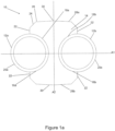
- the heat transfer member 14 shown in Figures 1 to 3 has an I-shaped profile, with the support formations 16a, 16b being formed as semi-circular indentations which receive the respective conduit 12a, 12b.
- the support formations 16a, 16b are formed in the heat transfer member 14 so that the first and second conduits 12a, 12b are positioned side by side and share a central axis.
- the heat transfer member 14 also includes engagement surfaces 22 which are configured to engage with an engagement surface of a further heat exchanger (as described in more detail below in relation to Figures 2 and 3 ).
- the engagement surfaces 22 are formed at either side of the support formations 16a, 16b and extend perpendicular to a first axis A 1 (as described in more detail below) so as to abut another engagement surface of a further heat exchanger to arrange the heat exchangers in a linear fashion relative to one another.
- the heat exchanger 10 is symmetrical about a first axis A 1 which passes through the heat transfer member 14 and the centre of the both first and second conduits 12a, 12b.
- the heat exchanger 10 is also symmetrical about a second axis A 2 which passes through the centre of the heat transfer member 14 and is perpendicular to the first axis A 1 .
- the heat transfer member 14 may be formed by extrusion, hot rolling or cold drawing.
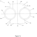
- FIGS 1a and 1b Two different profiles of the heat transfer member 14 are shown in Figures 1a and 1b .
- the heat transfer member 14 includes a welding chamfer 24 at each corner 26 of the heat transfer member 14.
- the heat transfer member 14 in Figure 1b does not include a chamfer at each corner 26.
- the top and bottom surfaces 28a, 28b i.e. the surfaces devoid of support formations 16a, 16b, of the heat transfer member 14 include a peak 30 midway along the surface 28a, 28b.
- the surfaces 28a, 28b extend at an angle, e.g. 3°, from the peak 30 towards a respective corner 26 of the heat transfer member 14.
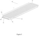
- FIGS 2 and 3 show a heat exchanger assembly 40 that includes a plurality of the heat exchanger 10 shown in Figure 1b .
- the heat exchanger assembly 40 may instead include a plurality of the heat exchanger 10 shown in Figure 1a .
- the heat exchangers 10 are arranged adjacent to one another so that neighbouring heat transfer members 14 share a conduit 12. More specifically, what was the exposed portion 20 of each conduit 12 is received by a support formation 16 of a neighbouring heat transfer member 14 so that the exposed portion 20 becomes another contact portion 18 of each conduit 12. In this way, each conduit 12 is fully enclosed by neighbouring heat transfer members 14.
- the plurality of conduits 12 are arranged linearly relative to one another. More specifically, the engagement surfaces 22 on one side of the heat transfer member 14 abut engagement surfaces 22 on a side of a neighbouring heat transfer member 14.
- the heat exchangers 10 are joined to one another along the abutment of neighbouring heat transfer members 14. Typically, the joining will be carried out by welding along the length L of the heat transfer members 14. Where a plurality of heat transfer members 14 as shown in Figure 1a are included in a heat exchanger assembly 40, the welding chamfers 24 define a small gap between neighbouring heat transfer members 14 and this is where welding takes place.
- the heat exchanger assembly 40 has two end heat exchangers 42 and a plurality of intermediate heat exchangers 44 posited between the end heat exchangers 42.
- the intermediate heat exchangers 44 are identical to the heat exchanger 10 described above in relation to Figure 1b .
- the end heat exchangers 42 differ in that they include only a single conduit 12 which is shared with a neighbouring intermediate heat exchanger 44.
- the support formation 16 at each end of the heat exchanger assembly 42 is "empty", i.e. it has no conduit 12 received therein.
- the end heat exchangers 42 may not have an empty support formation 16 and may instead include a conduit 12 which is left exposed. In further embodiments of the invention, the end heat exchangers 42 may differ from the intermediate heat exchangers 44 in that the heat transfer member 14 may only include a single support formation 16 which receives a shared conduit 12.
- a heat exchanger for a thermochemical biomass converter according to a second embodiment of the invention is shown in Figures 4 to 6b and is designated generally by reference numeral 50.
- the heat exchanger 50 includes first and second conduits 52a, 52b and a heat transfer member 54 that thermally connects the first and second conduits 52a, 52b to one another to define a heat transfer medium between the conduits 52a, 52b.
- the first and second conduits 52a, 52b are configured to carry process medium of the thermochemical biomass converter in which the heat exchanger 50 is incorporated.
- the thermal expansion coefficient of the first and second conduits 52a, 52b matches that of the heat transfer member 54 so as to continually provide thermal connection between the heat transfer member 54 and conduits 52a, 52b under changing temperature conditions.
- the heat transfer member 54 has first and second support formations 56a, 56b that position and support the first and second conduits 52a, 52b within the heat exchanger 50.
- the first support formation 56a abuts a contact portion 58a of the first conduit 52a
- the second support formation 56b abuts a contact portion 58b of the second conduit 52b.
- the remainder of the first and second conduits 52a, 52b, i.e. which is not being supported by the support formations 56a, 56b, is left exposed relative to the corresponding support formation 56a, 56b.
- the split between the exposed portion 60a, 60b and the contact portion 58a, 58b of each conduit 52a, 52b is 50:50, i.e. the contact portion 58a, 58b extends over half of the surface of the corresponding conduit 52a, 52b leaving the other half exposed.
- the contact portion 58a, 58b may extend over more or less than half of the surface of the corresponding conduit 52a, 52b.
- the support formations 56a, 56b are formed as semi-circular indentations within the heat transfer member 54, which receive the respective conduit 52a, 52b.
- the heat transfer member 54 also includes engagement surfaces 62, which are configured to engage with an engagement surface of a further heat exchanger (as described in more detail below in relation to Figures 5 , 6a and 6b ).
- the engagement surfaces 62 are formed at either side of the support formations 56a, 56b and extend at an angle relative to a first axis A 1 (as described in more detail below) so as to abut another engagement surface of a further heat exchanger to arrange the heat exchangers 50 radially relative to one another.
- the heat exchanger 50 is asymmetrical about a first axis A 1 which passes through the heat transfer member 54 and the centre of the both first and second conduits 52a, 52b. More specifically, the heat transfer member 54 tapers from a wider portion 64 on one side of the first axis A 1 to a narrower portion 66 on the other side of the first axis A 1 .
- the heat exchanger 50 is symmetrical about a second axis A 2 which passes through the centre of the heat transfer member 54 and is perpendicular to the first axis A 1 .
- the heat exchanger 50 forms a segment of a circular array of heat exchangers 50 (as described below in more detail in relation to Figures 5 , 6a and 6b ).
- the narrow portion 66 of the heat transfer member 54 coincides with a centre C of the circular array and the wider portion 64 coincides with a circumference 82 of the circular array (the centre C and circumference 82 are shown in Figure 5 ).
- the engagement surfaces 62 are angled relative to the centre C of the circular array and the angle is chosen depending on the number heat exchangers 50 that are required in the circular array. In the embodiment shown in Figure 4 , the angle between the opposing engagement surfaces 62 is 60°.
- the opposing engagement surfaces 62 located towards the wider portion 64 of the heat transfer member 54 include a welding cutaway 68 so that those engagement surfaces 62 extend at a different angle to the engagement surfaces 62 located towards the narrow portion 66 of the heat transfer member 54.
- the cutaway 68 forms an angle of 20° between the engagement surfaces 62 at the wider portion 64 of the heat transfer member 54 and the engagement surfaces 62 at the narrow portion 66.
- the wider portion surface 70 of the heat transfer member 54 includes a peak 72 midway along the surface 70.
- the surface 70 extends at an angle, e.g. 3°, from the peak 72 towards a respective corner 74, i.e. towards the cutaway 68 in this embodiment, of the heat transfer member 54.
- the heat transfer member 54 may be formed by extrusion or cold drawing, or a combination of these methods as well as steel casting methods, such as die casting or continuous casting.
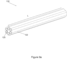
- FIGS 5 , 6a and 6b show a heat exchanger assembly 80 that includes a plurality of the heat exchanger 50 shown in Figure 4 .
- first and “second” components are not referred to as “first” and “second” and have been designated a single reference numeral (i.e. "52” instead of “52a") in the description below in relation to the heat exchanger assembly 50 in Figure 4 .
- the heat exchangers 50 are arranged adjacent to one another so that neighbouring heat transfer members 54 share a conduit 52. More specifically, what was the exposed portion 60 of each conduit 52 is received by a support formation 56 of a neighbouring heat transfer member 54 so that the exposed portion 60 becomes another contact portion 58 of each conduit 52. In this way, each conduit 52 is fully enclosed by neighbouring heat transfer members 54.
- the heat transfer members 54 are arranged in a circular array such that the plurality of conduits 52 are arranged also in a circular array. More specifically, the angled engagement surfaces 62 on one side of the heat transfer member 54 abut the angled engagement surfaces 62 on a side of a neighbouring heat transfer member 54. Moreover, as indicated above, the wider portion 64 of the array of heat transfer members 54 forms the circumference 82 of the assembly 80, and the narrow portions 66 of each heat transfer member 54 form the centre C of the assembly 80.
- the heat exchangers 50 are joined to one another along the abutment of neighbouring heat transfer members 54. Typically, the joining will be carried out by welding along the length L of the heat transfer members 54 at the gap 84 created by neighbouring cutaways 68 of the heat transfer members 54.
- Figure 6a shows the heat exchanger assembly 80 extending in the lengthwise L direction in a straight line, i.e. for use with straight sections of conduits 52.
- Figure 6b shows the heat exchanger assembly 80 extending in the lengthwise L direction in a curved manner, i.e. for use with bent/curved sections of conduits 52 (which are omitted from Figure 6b for clarity purposes).
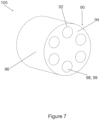
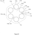
- a heat exchanger for a thermochemical biomass converter according to a third embodiment of the invention is shown in Figure 7 and is designated generally by reference numeral 90.
- the heat exchanger 90 includes conduits 92 and a heat transfer member 94 that thermally connects the conduits 92 to one another to define a heat transfer medium between the conduits 92.
- the heat transfer member 94 is a portion of a single piece heat transfer member block 96.
- the heat transfer member block 96 has openings 98 formed therein to receive a respective conduit 92.
- the openings 98 are formed by drilling a hole in the block 96. As shown, there are six openings 98 to receive six conduits 92. However, fewer or more openings 98 may be present.
- conduits 92 are configured to carry process medium of the thermochemical biomass converter in which the heat exchanger 90 is incorporated.
- the thermal expansion coefficient of the conduits 92 matches that of the heat transfer member 94 so as to continually provide thermal connection between the heat transfer member 94 and conduits 92 under changing temperature conditions.
- the openings 98 formed in the heat transfer member 94 define support formations 99 that position and support a respective conduit 92 within the heat exchanger 90.
- the heat exchanger 100 has a circular profile such that the conduits 92 are arranged in a circular array.
- a heat exchanger for a thermochemical biomass converter according to a fourth embodiment of the invention is shown in Figures 8 to 9b and is designated generally by reference numeral 110.
- the heat exchanger 110 includes first and second conduits 112a, 112b and two discrete heat transfer members 114a, 114b.
- the discrete heat transfer members 114a, 114b cooperate with one another to thermally connect the first and second conduits 112a, 112b to one another to define a heat transfer medium between the conduits 112a, 112b.
- the first and second conduits 112a, 112b are configured to carry process medium of the thermochemical biomass converter in which the heat exchanger 110 is incorporated.
- the thermal expansion coefficient of the first and second conduits 112a, 112b matches that of the discrete heat transfer members 114a, 114b so as to continually provide thermal connection between the discrete heat transfer members 114a, 114b and the conduits 112a, 112b under changing temperature conditions.
- Each of the discrete heat transfer members 114a, 114b includes a respective first and second support formation 116a, 116b.
- the first support formations 116a of each of the discrete heat transfer members 114a, 114b is configured to position and support the first conduit 112a within the heat exchanger 110
- the second support formations 116b of each of the discrete heat transfer members 114a, 114b is configured to position and support the second conduit 112b within the heat exchanger 110.
- each of the discrete heat transfer members 114a, 114b is a portion of a respective single piece heat transfer member block 118a, 118b, which is described in more detail below.
- each discrete heat transfer member 114a, 114b may instead be a standalone component, which can be joined, e.g. welded, to a neighbouring discrete heat transfer member 114a, 114b so as to share a conduit 112.
- the discrete heat transfer members 114a, 114b may be so joined in a linear manner (much like the heat exchanger assembly 40 described in relation to Figures 2 and 3 ) or in a circular manner (much like the heat exchanger assembly 80 described in relation to Figures 4 to 6b ).
- first heat transfer member block 118a defines an inner block 120 and the second heat transfer member block 118b defines an outer block 122, and the conduits 112a, 112b are arranged radially relative to one another.
- the inner and outer blocks 120, 122 define further first and second support formations 116a, 116b arranged in a circular array relative to one another such that further conduits 112 are also arranged in a circular array. In this way, the inner and outer blocks 120, 122 and conduits 112 define a heat exchanger assembly 130.
- conduits 112 included in the heat exchanger assembly 130, but there may be more or fewer conduits 112.
- the inner block 120 has a star-shaped profile.
- the arms 132 of the star extend outwards and in between neighbouring conduits 112.
- the outer block 122 has arms 134 that extend inwards and in between neighbouring conduits 112. Pairs of arms 132, 134 of the inner and outer blocks 120, 122 meet one another at a contact point 136 located between neighbouring conduits 112.
- the outer profile of the outer block 122 has a hexagonal shape, but this may take another form (e.g. circular).
- the outer and inner blocks 120, 122 may be formed by extrusion, casting or cold drawing.
- the heat exchanger assembly 130 can be assembled without the need for joining such as welding. Instead, the components can be assembled using a hot assembly process wherein the conduits 112 are arranged in the support formations 116 of the inner block 120, and then the outer block 122 is heated, e.g. to 700°C, and slid over the conduits 112.
- Figure 9a shows the heat exchanger assembly 130 extending in the lengthwise L direction in a straight line, i.e. for use with straight sections of conduits 112 (which are omitted from Figure 9a for clarity purposes).
- Figure 9b shows the heat exchanger assembly 130 extending in the lengthwise L direction in a curved manner, i.e. for use with bent/curved sections of conduits 112 (which are omitted from Figure 9b for clarity purposes).
- Figure 10 shows a flange 131 with clamp 133 to hold together the linear heat exchanger assembly 40 shown in Figures 2 and 3 .
- the flange 131 is shown in perspective to show the holes 132 going though the flanges to connect to the conduits 12.
- the flanges with clamps provide an efficient means of connecting modular units of heat exchanger conduits, and is based on the principles from commercial high pressure clamp assemblies such and Grey-Lok TM and Techloc TM clamps.
- the combined assembly 140 combines two linear assemblies 40 employing two flanges 131 two clamps 133 bolted together with bolts going going through the bolt holes 134. Other designs, such as regular bolted flanges may be used as well, but the clamp design shown in Figure 10 has the advantage of a more compact design and ease of alignment.
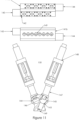
- Figure 11 shows an example of a combined manifold and valve distributor 150, which provides a means of controlling the individual flow in the parallel heat exchanger conduits which allows variations in flow and pressure in the heat exchanger. Such variations are very beneficial for reducing tendencies for a fouling layer build up, as controlled flow or pressure pulses are an efficient means to remove or reduce potential deposits. In addition, it allows to compensated for the lower heat transfer to the outer conduits in the geometrical assembly, which only receive heat from one conduit instead of two.
- the valve head assemblies with the corresponding actuators have been omitted on the overview drawing of the clamp 141a and 141b, indicating only the mounting holes 142 for the valvehead assemblies.
- valve seat 143 the valve plunger 146, the valvehead sealing unit 147 and the valve actuator 148 can be seen
- the combined unit can be connected via the connector holes 149 in the unit to a flange 131, whereas the inlet to one set of conduits 12 is fed via a common feed tube 144 and the outlet the other set of conduits are joined in the outlet tube 145.
- the manifold and valve distributor can be assembled with the conduit assembly 40 using a flange 131 and clamps 133 as described above for figure 10 .
- any one of the heat exchanger assemblies 40; 80; 100; 130; 140; 150 is incorporated into a thermochemical biomass converter (not shown).
- the process medium (typically highly corrosive) of the converter is fed through the conduits 12; 52; 92; 112 typically at high temperature, high pressure conditions. Heat from the process medium is transferred through the thin walls of the conduits 12; 52; 92; 112 and is transferred through the transfer medium defined by the heat transfer member 14; 54; 94; 114.
- First and second conduits refers to piping made from a material with advantageous heat exchange properties adapted to carry fluids having first and second characteristics respectively, such as a “hotter” and “cooler” process streams or process streams “before” and “after” thermal conversion. It will be readily understood by one skilled in the art that a heat exchanger comprising "first and second conduits" may have more than one first and more than one second conduit.
- Heat transfer member refers to a structural element formed from a material with advantageous heat exchange properties that provides a means of heat transfer.
- “Support formation” refers to a contour of a heat transfer member that provides a spatially complementary fit and thereby structural support to all or part of a conduit or to all or part of a first and/or second conduit.
- Heat transfer surface refers to a surface on a heat transfer member which is designed to provide a close thermal contact and spatial fit with a corresponding surface on another heat transfer member to permit assembly of a plurality of individual heat exchangers into a collective form.
- heat transfer members are made from carbon steel, cast iron, ductile cast iron, or steel alloys such as alloy 1120, 4140, 4330, or S55C .
- conduits are made from nickel-chromium-molybdenum-tungsten alloys such as Hastelloy C, or high-silicon nickel-chromium alloys such as Hastelloy D, or nickel-chromium alloys such as Inconel 200 or Inconel 625, or cobalt-nickel- chromium-tungsten alloys such as Haynes alloy 25, or stainless steel-chromium alloys such as 17-7PH, or titanium-manganese alloys such as Ti-8Mn.
- nickel-chromium-molybdenum-tungsten alloys such as Hastelloy C
- high-silicon nickel-chromium alloys such as Hastelloy D
- nickel-chromium alloys such as Inconel 200 or Inconel 625
- cobalt-nickel- chromium-tungsten alloys such as Haynes alloy 25, or stainless steel-chromium alloys such as 17-7PH, or titanium-manganese alloys such as Ti-8Mn.
- Table 1 shows representative examples of advantageous pairings of materials for conduits and heat transfer members, showing linear thermal expansion coefficients of each.
- Table 1 Examples of materials selections and their linear thermal expansion coefficients First and second conduit Heat transfer member First and second conduit Heat transfer member difference linear thermal exp x10 +6 (K-1) linear thermal exp x10 +6 (K-1) 1 Inconel 625 (UNS 6625) Carbon steel A36 12.8 11.7 1.1 2 Hastelloy D Grey Cast Iron - G3000 11.0 11.4 0.4 3 Hastelloy C Ductile cast iron -60-40-18 11.3 11.2 0.1 4 Inconel 200 Steel alloy 1120 11.7 12.3 0.6 5 Stainless steel alloy 17-7PH Steel alloy S55C 11.0 11.7 0.7 6 Titanium Alloy Ti-8Mn Steel alloy 4140 10.8 11.5 0.7 7 Haynes Alloy 25 Steel alloy 4330 12.3 12.3 0 Callister.W.D,JR.
- first and second conduits are each made from the same material and have the same physical characteristics.
- conduit wall thickness is within the range 0.02 mm and 0.15 times the average internal diameter of the conduit.
- conduit internal diameter is within the range 10-80 mm, or 15-60 mm, or 20-50 mm.
- conduits in the absence of structural support from a heat transfer member have pressure rating between 10 and 40 bar.
- the thermal expansion coefficient of material used to make conduits is matched to the thermal expansion coefficient of material used to make heat transfer members such that the difference between the thermal expansion coefficients is within the range 0.0 ⁇ 10-6 K-1 to 2.5 ⁇ 10-6 K-1.
- the invention provides a heat exchanger for a thermochemical biomass converter comprising-
- the at least two conduits correspond to a first and second conduit adapted to carry process stream before and after thermal conversion respectively.
- the heat transfer member is a single piece providing support formation contacting the entire surface of the at least two conduits such that the heat exchanger is functional without requirement for joining a plurality of individual heat exchangers into a collective form.
- the support formation of a heat transfer member contacts only a part of the surface of each of the at least two conduits and the heat exchanger is designed to be joined as an individual component with a plurality of similar individual heat exchangers to form a collective assembly.
- individual heat exchangers comprise a heat transfer member having engagement surfaces to facilitate assembly of a plurality of individual heat exchangers into a collective assembly.
- the individual heat exchanger is symmetrical about a first axis which passes through the heat transfer member and center of each of the at least two conduits and is further symmetrical about a second axis which passes through the center of the heat transfer member and which is perpendicular to the first axis.
- the heat transfer member has an I-shaped profile with support formations as two semi-circular indentations each bounded by flat engagement surfaces that are perpendicular to the first axis.
- the individual heat exchanger tapers from a wider portion on one side of the first axis to a narrow portion on the other side of the first axis and is adapted to be joined with a plurality of similar individual heat exchangers as a circular array by having a heat transfer member with engagement surfaces that extend at an angle relative to the first axis.
- Heat transfer members can typically be formed by extrusion, hot rolling, cold drawing or molding. Conduits can be either seamless or welded piping. When assembling a heat exchanger of the invention, including collective assemblies of a plurality of individual heat exhangers, conduits can be made with slight differences of fit to permit intentional expansion of the material into an expanded fit with the heat transfer member. Expansion of conduits into an expanded fit can be conducted by a variety of mean known in the art including mechanical or hydraulic expansion.
- test sections of the heat exchanger shown in Figure 7 were produced.
- a 0.55 m section with 3 hot conduit tubes (transfer of heat) and 3 cold conduit tubes (receiving heat) made out of a high nickel and chrome alloy (UNS 6625) was ordered in a hexagonal and alternating pattern inside a 100 black steel (A36S) rod acting as the heat transfer member and having thermal expansion coefficient of 12.5 ⁇ 10-6 K-1.
- the 6 conduit tubes each having a pressure rating of 70 bar, a thermal expansion coefficient of 12.7 ⁇ 10-6 K-1, an internal diameter of 23.6 mm and a wall thickness of 1.6 mm were placed inside 27.2 mm through holes drilled in the solid steel rod along the length of the rod with 60° separation between holes.
- the thin walled alloy tubes were at the ends mechanically expanded and welded to a 120 mm diameter 12 mm thick seal plate in the same high alloy steel, and the unit was then equipped with heavy duty flanges welded to the ends of the heat transfer member.
- the inner tube was hydraulically expanded using water as pressure medium to a pressure of 1000 bar, which is well above the hydraulic pressure needed to give permanent deformation of the inner tube.
- the unit was filled with water inside the six conduit tubes, which in one end were closed with high pressure resistant plugs and in the other end with corresponding plugs with hydraulic connectors.
- the hydraulic connectors were connected to an air driven high pressure pump (RESATO Tm model MPS) via high pressure hydraulic hoses, and were expanded to the desired pressure in 100 bar steps to the desired pressure in this case 1000 bar.
- RSATO Tm model MPS air driven high pressure pump
- the assembly in example 1 was further hydraulically expanded to 1500 bar.
- a 2.75 m long test heat exchanger was prepared by welding together 5 pieces of predrilled heat transfer member together with careful alignment, and lining these with thin walled high alloy conduit tubes and seal plates as well as heavy duty steel flanges as described in example 1.
- the inner tube/liner was expanded using a hydraulic pressure of 800 bar according to the procedure in example 1.
- the assembly in example 3 was further hydraulically expanded to 1500 bar.
- the heat transfer was measured at relatively low temperature as seen below and at low pressure (2-5 bar). These conditions are especially challenging and relevant for the evaluation of the heat exchange efficiency, as the low pressure will not contribute to (i) the mechanical thermal contact between the conduits and the heat transfer member and (ii) the radiative and convective heat transfer via imperfections in the interface between the conduits and the heat transfer member at these relatively low temperatures.
- the thermal transfer was measured by careful logging of the inlet temperature and the outlet temperature of the hot and the cold stream simultaneously as well as the volumetric flow though the hot and the cold conduits. The energy transfer is calculated as flow ⁇ Temperature difference ⁇ heat capacity of the water. The numbers given in table ⁇ are the average of the values for the hot and cold streams.
- Table 2 Flow (l/min for 3 tubes) Temperature Difference (°C) Expansion pressure (Bar) Energy transfer (KW/m) 1 20 28 800 1.7 2 40 28 800 2.9 3 62 28 800 3.4 4 40 40 800 4.0 5 68 40 800 5.3 6 20 28 1500 2.7 7 40 28 1500 4.0 8 62 28 1500 5.4 9 40 40 1500 6.8 10 68 40 1500 9.0
Description
- This invention relates to a heat exchanger for a thermochemical biomass converter.
- Thermochemical biomass converters typically work in high temperate, high pressure conditions and with highly reactive process medium (e.g. aqueous acids or bases, polar solvents like ethanol or tetrahydrofurane, or mixtures thereof). The process medium also typically has a high viscosity due to the biomass content and is thus prone to clogging. This is particularly true of thermochemical converters using hydrothermal conversion, including hydrothermal liquefaction (HTL), hydrothermal carbonization (HTC), or hydrothermal gasification. In such conversion processes, highly viscous suspensions of biomass are heated to 190°C to 450°C at pressures of between 50 to 300 bar. Moreover, biomass conversion may be improved by adding strong oxidants (e.g. oxygen or hydrogen peroxide) in the so-called hydrothermal wet-oxidation processes or reducing agents such as formic acid or hydrogen (hydrotreatment). In these cases, the corrosively of the medium is significantly enhanced beyond the already corrosive properties of high temperature, pressurized water and organic acids evolved during the conversion process. Corrosively thus poses extra challenges to the selection of materials for conversion systems. The economy of all these processes is highly dependent on efficient heat recovery and thus efficient heat exchangers are vital to the success and viability of the processes.
- It is known to transfer heat from one medium to another to either cool or heat the medium. However, in thermochemical conversion, and more specifically hydrothermal conversion, the heating and cooling operational expenses can ruin process economy completely if efficient heat exchange cannot be obtained. Moreover, the processes are commonly favored by high heating and cooling rates to avoid side-reactions that are prone to occur at intermediate temperatures.
- A known heat exchanger is disclosed in United States patent application
US 2017/233327 . E.g., the heat exchanger may be a tube-by-tube configuration joined in a highly thermally conductive material. The heat exchanger may comprise two tube parts joined together in a solid matrix of relatively good heat conducting material. - According to a first aspect of the invention there is provided a heat exchanger for a thermochemical biomass converter, the heat exchanger comprising first and second conduits being configured to carry, in use, process medium of the converter, and a heat transfer member thermally connecting the first and second conduits to one another to define a heat transfer medium between the conduits, wherein the heat transfer member includes first and second support formations configured to position and support a respective first and second conduit in the heat exchanger,
- characterized in that the heat transfer member has a higher heat conductivity than the materials used for the first and second conduit; and
- wherein the conduits are made with an intentional expansion of the conduit material into an expanded fit with the heat transfer member;
- and further characterized in that conduits in the absence of structural support from a heat transfer member have pressure rating within the range 5 to 75 bar but in combination with a single heat transfer member or with a plurality of similar individual heat transfer members can operate at pressures within the
range 100 to 300 bar. - Using the temperature difference between the first and second conduits, and thus between the process medium in the converter, to cause heat transfer means that direct heat exchange between the process medium is achieved. This is in contrast to using an external heat transfer medium, e.g. steam, molten salt or thermal oil, which would require more components and thus increase the size, cost and complexity of the heat exchanger.
- In particular, the temperatures needed especially for HTL and HTG conversion processes are so high that there would be severe stability issues with using thermal oils as an external heat transfer medium. If water/steam is used the pressure in the secondary heat transfer circuits may exceed pressures corresponding to supercritical temperatures, thus adding significantly to the risk and cost of such conversion processes. Molten salt could be used, but the properties of such media are prone to create significant problems in terms of corrosion and in terms of loss of power clogging due to solidification. Moreover, in each case, the use of an external heat transfer medium would require two thermal transfer processes i.e. one from the hot process stream to the external heat transfer medium and another from this to the cold process stream, thus increasing the potential for losses in the heat transfer process.
- In addition to the foregoing, standard known external heat exchangers such as plate, shell, tube/double tube and spiral, are not effective under the extreme conditions (i.e. high pressure, high temperate conditions with high viscosity medium that is prone to clogging) of a thermochemical biomass converter. For plate heat exchangers, this is because they cannot withstand the very high pressures; for tube in tube heat exchangers, clogging will occur due to the narrow passage in the outer shell; for shell and tube heat exchangers, the problems are in relation to the high pressure on the outer shell and to the limited degree of ideal counter current heat exchange that is needed in this process (this is in addition to possible clogging issues); for spiral heat exchangers, there are pressure limitations and clogging issues means that they are not suited for extreme conditions.
- Direct heat exchange between feed stream and product stream allow efficient and balanced recovery of thermal energy. Also, since the flows can be made perfectly counter current, a high thermal transfer rate can be obtained.
- Meanwhile, the use of heat transfer members including first and second support formations means that the conduits can be made from a thin amount of material because they are provided with structural support from the heat transfer member. The conduits being made from a thin amount of material reduces costs because less of the expensive conduit material is required. The conduits are expensive because the material that they are made from must be able to withstand the high temperature and highly corrosive process medium of the converter, and so the heat exchanger requiring less of this material reduces the overall cost. In contrast, the heat transfer member, which does not contact the process medium, does not require properties which can withstand direct contact with the high temperature and highly corrosive process medium. Instead, the heat transfer member needs only to be thermally conductive and strong enough to provide structural support to the conduits. A wide variety of materials with such properties are available, and so a low-cost material can be selected for the heat transfer member to reduce the overall cost of the heat exchanger.
- Moreover, the conduits being made from a thin amount of material helps to facilitate the direct heat transfer between the conduits. In this regard, the types of materials that are able to withstand the extreme conditions that the conduits are exposed to tend to have poor heat conductivity. Thus, the thin conduits permit a greater heat transfer between the conduits.
- Preferably, the first and second support formations of the heat transfer member are integrally formed with the heat transfer member such that it has a profile that is complimentary to the profiles of the first and second conduits.
- The thermal expansion coefficient of the first and second conduits may be matched to the thermal expansion coefficient of the heat transfer member to continually provide thermal connection between the heat transfer member and the conduits under changing temperature conditions.
- Matching the thermal expansion coefficients of the heat transfer member and both conduits means that the thermal connection between the conduits (as provided by the heat transfer member) remains good throughout operation of the thermochemical biomass converter (during which there will be changing temperature conditions). If the thermal expansion coefficients were not matched correctly then compression or expansion can occur in the components, thus rendering the heat exchanger unworkable.
- It will be understood that the thermal expansion coefficients of the conduits and the heat transfer member being "matched" means that they must be suitably similar (not necessarily the identical) so that the heat transfer member is able to continue to operate as a heat transfer medium between the two conduits throughout operation of the converter.
- The thermal expansion coefficient of the first and second conduits may be matched to the thermal expansion coefficient of the heat transfer member to a difference of less than 2.5 ×10⁻⁶ K-1. Preferably, the thermal expansion coefficient of the first and second conduits is matched to the thermal expansion coefficient of the heat transfer member to a difference of less than 1.5 ×10⁻⁶ K-1, and more preferably to a difference of less than 0.5×10⁻⁶ K-1.
- Matching the thermal expansion coefficients of the conduits to that of the heat transfer member in such orders of magnitude provides reliable and efficient heat exchange under changing temperature conditions of the thermochemical biomass converter.
- Preferably, the first and second conduits are made from a nickel alloy. Preferably, the first and second conduits are made solely from such nickel alloy. More preferably, the first and second conduits are made from (optionally, solely from) nickel-chromium-based super-alloys. One such super-alloy is Inconel®, such as Inconel® 625.
- Preferably, the heat transfer member is made from steel. The steel may be any steel providing it has more than 90% Fe content (i.e. it is a steel, rather than an iron alloy).
- Optionally the first and second support formations are configured to provide a spatially complementary fit to a contact portion of a respective first and second conduit, the remaining portion of each first and second conduit being left exposed relative to the respective support formation.
- The support formations abutting a contact portion of a respective conduit while leaving another portion exposed allows the support formations to provide support to a respective conduit (i.e. at the contact portion) while permitting ready assembly of another heat exchanger in relation to the exposed portion of the conduits. This means that each conduit can form part of a further heat exchanger for direct heat exchange from that conduit to another, further conduit. In other words, each conduit can be shared between neighbouring heat exchangers in a heat exchanger assembly.
- In one embodiment of the invention the heat transfer member may include an engagement surface configured to engage with an engagement surface of a further heat exchanger to arrange the heat exchangers linearly relative to one another.
- The inclusion of such an engagement surface permits the heat exchanger to be coupled to additional heat exchanger to increase the efficiency of the heat exchange properties. The engagement surface permitting the heat exchangers to be arranged linearly relative to one another means that any number of heat exchangers can be arrangement relative to one another in an easily assembled manner.
- In another embodiment of the invention the heat transfer member may include an engagement surface configured to engage with an engagement surface of a further heat exchanger to arrange the heat exchangers radially relative to one another.
- The inclusion of such an engagement surface permits the heat exchanger to be coupled to additional heat exchangers to increase the efficiency of the heat exchange properties. The engagement surface permitting the heat exchangers to be arranged radially relative to one another means that the heat exchangers can be arranged in a circular fashion. Such an arrangement is particularly useful where the heat exchangers share a conduit between them, and so the circular arrangement forms a "closed" system in the sense that no conduits are left exposed. Therefore, the conduits in such an assembly are exchanging heat at both sides.
- Optionally the heat exchanger includes two discrete heat transfer members, the two discrete heat transfer members cooperating with one another to thermally connect the first and second conduits to one another to define a heat transfer medium between the conduits.
- Including two such heat transfer members allows different securing techniques to be used to assemble the heat exchanger with further heat exchangers. Moreover, different materials for the discrete heat transfer members can be chosen depending on the requirements of the heat exchanger.
- According to second aspect of the invention there is provided a heat exchanger assembly including a plurality of heat exchangers as described hereinabove arranged adjacent to one another so that neighbouring heat transfer members share a conduit.
- The advantages of the heat exchanger of the first aspect of the invention and its embodiments applies mutatis mutandis to the heat exchanger assembly of the second aspect of the invention and its embodiments.
- The plurality of first and second conduits may be linearly arranged relative to one another. The plurality of first and second conduits may instead be annularly arranged relative to one another.
- Optionally, each heat transfer member is a portion of a single piece heat transfer member block.
- The heat transfer members being a portion, i.e. section, of a single piece heat transfer member block means that no joining, e.g. welding, is required to form the heat exchanger assembly. A heat exchanger assembly may typically be 150m long, and so a significant amount of additional material, time and weight is saved by not requiring joining, e.g. welding, of the components.
- In embodiments wherein two discrete heat transfer members (which cooperate with one another to thermally connect the first and second conduits to one another) are included, each of the discrete heat transfer members may be a portion of a respective single piece heat transfer member block.
- Moreover, the plurality of first and second conduits may be annularly arranged relative to one another with one of the heat transfer member blocks being positioned as an inner block and the other of the heat transfer member blocks being positioned as an outer block relative to the annular array of conduits.
- Such an arrangement does not require any joining, e.g. welding, to form the heat exchanger assembly since the single piece inner and outer heat transfer member blocks and the conduits can be fitted together (e.g. by performing a hot assembly) to secure each component in place. A heat exchanger assembly may typically be 150m long, and so a significant amount of additional material, time and weight is saved by not requiring joining, e.g. welding, of the components.
- According to a third aspect of the invention there is provided a thermochemical biomass converter including a heat exchanger as described hereinabove.
- The advantages of the heat exchanger of the first aspect of the invention and its embodiments applies mutatis mutandis to the thermochemical biomass converter of the third aspect of the invention and its embodiments.
- Preferred embodiments of the invention will now be described, by way of non-limiting examples, with reference to the accompanying drawings in which:
-
Figure 1a shows a profile view of a first example of a heat exchanger according to a first embodiment of the invention; -
Figure 1b shows a profile view of a second example of a heat exchanger according to the first embodiment of the invention; -
Figure 2 shows a profile view of a heat exchanger assembly including a plurality of the heat exchangers shown inFigure 1b ; -
Figure 3 shows a perspective view of the heat exchanger assembly ofFigure 2 ; -
Figure 4 shows a profile view of a heat exchanger according to a second embodiment of the invention; -
Figure 5 shows a profile view of a heat exchanger assembly including a plurality of the heat exchangers shown inFigure 4 ; -
Figure 6a shows a perspective view of the heat exchanger assembly ofFigure 5 with a straight longitudinal profile; -
Figure 6b shows a perspective view of the heat exchanger assembly ofFigure 5 with a curved longitudinal profile; -
Figure 7 shows a profile view of a heat exchanger according to a third embodiment of the invention forming part of a heat exchanger assembly; -
Figure 8 shows a profile view of a heat exchanger according to a fourth embodiment of the invention forming part of a heat exchanger assembly; -
Figure 9a shows a perspective view of the heat exchanger assembly ofFigure 8 with a straight longitudinal profile; -
Figure 9b shows a perspective view of the heat exchanger assembly ofFigure 8 with a curved longitudinal profile; -
Figure 10 shows a clamp flange system for the assembly of heat exchanger sections, and -
Figure 11 shows a manifold with integrated valve distributor to allow for individual control of the flow in each conduit. The valve heads with actuators are omitted for clarity. - A heat exchanger for a thermochemical biomass converter according to a first embodiment of the invention is shown in
Figures 1 to 3 and is designated generally byreference numeral 10. - The
heat exchanger 10 includes first andsecond conduits heat transfer member 14 that thermally connects the first andsecond conduits conduits 12a - The first and
second conduits heat exchanger 10 is incorporated. The process medium being carried by thefirst conduit 12a may be a feed stream, e.g. sewage sludge with dry matter content of 20% in water or fibrous woody biomass with dry matter content of 16% in water with added sodium hydroxide, which has a first temperature. The process medium being carried by thesecond conduit 12b may be a product stream, e.g. a complex stream of high viscosity biocrude in water together with dissolved carbon dioxide and suspended solids, which has a second temperature. The first and second temperatures differ from one another. For example, cold, e.g. 20°, feed stream is heated using the product stream (plus extra energy) to a high temperature, e.g. 350°, then once the reaction has taken place the feed stream is used to cool it down to e.g. 50°. - The thermal expansion coefficient of the first and
second conduits heat transfer member 14 so as to continually provide a thermal connection between theheat transfer member 14 andconduits - In the embodiment shown, the first and
second conduits conduits - The first and
second conduits heat transfer member 14 is made from a cast steel which results in the thermal expansion coefficients of the two materials being matched to a difference of 0.2 ×10⁻⁶ K-1. - In other embodiments of the invention, the first and
second conduits heat transfer member 14 may be made from any other suitable materials which result in the thermal expansion coefficients of the two materials being matched to a difference of less than 2.5 ×10⁻⁶ K-1, and preferably less than 1.5 ×10⁻⁶ K-1. Even more preferably, a difference of less than 0.5 ×10⁻⁶ K-1 - It will be understood that suitable materials for the
conduits second conduits - Meanwhile, the
heat transfer member 14 must have a higher heat conductivity and lower cost than the materials used for the first and second conduits and have sufficient strength characteristics to support the first andsecond conduits heat transfer member 14 may be made from low alloy steel, black steel, and other temperature resistant alloys such as high-performance brass alloys - The materials and thermal expansion coefficient properties outlined above apply mutatis mutandis to the conduit and heat transfer member components of each of the other embodiments described below and shown in the remaining figures.
- The
heat transfer member 14 has first andsecond support formation second conduits heat exchanger 10. - In the embodiment shown in
Figures 1a and1b , thefirst support formation 16a abuts acontact portion 18a of thefirst conduit 12a, and thesecond support formation 16b abuts acontact portion 18b of thesecond conduit 12b. The remainder of the first andsecond conduits support formations corresponding support formation portion contact portion conduit contact portion corresponding conduit contact portion corresponding conduit - The
heat transfer member 14 shown inFigures 1 to 3 has an I-shaped profile, with thesupport formations respective conduit support formations heat transfer member 14 so that the first andsecond conduits - The
heat transfer member 14 also includes engagement surfaces 22 which are configured to engage with an engagement surface of a further heat exchanger (as described in more detail below in relation toFigures 2 and3 ). The engagement surfaces 22 are formed at either side of thesupport formations - The
heat exchanger 10 is symmetrical about a first axis A1 which passes through theheat transfer member 14 and the centre of the both first andsecond conduits heat exchanger 10 is also symmetrical about a second axis A2 which passes through the centre of theheat transfer member 14 and is perpendicular to the first axis A1. - The
heat transfer member 14 may be formed by extrusion, hot rolling or cold drawing. - Two different profiles of the
heat transfer member 14 are shown inFigures 1a and1b . InFigure 1a , theheat transfer member 14 includes awelding chamfer 24 at eachcorner 26 of theheat transfer member 14. Theheat transfer member 14 inFigure 1b does not include a chamfer at eachcorner 26. - In both examples, the top and
bottom surfaces support formations heat transfer member 14 include apeak 30 midway along thesurface surfaces respective corner 26 of theheat transfer member 14. -
Figures 2 and3 show aheat exchanger assembly 40 that includes a plurality of theheat exchanger 10 shown inFigure 1b . Theheat exchanger assembly 40 may instead include a plurality of theheat exchanger 10 shown inFigure 1a . - Due to the arrangement of the
heat exchangers 10, as described in more detail below, what was a "first" component (e.g. conduit 12a,support formation 16a, etc.) inFigures 1a and1b of oneheat exchanger 10 becomes the "second" corresponding component of the neighbouringheat exchanger 10. For this reason, these components inFigures 2 and3 are not referred to as "first" and "second" and have been designated a single reference numeral (i.e. "12" instead of "12a") in the description below in relation to theheat exchanger assembly 40. - The
heat exchangers 10 are arranged adjacent to one another so that neighbouringheat transfer members 14 share aconduit 12. More specifically, what was the exposed portion 20 of eachconduit 12 is received by asupport formation 16 of a neighbouringheat transfer member 14 so that the exposed portion 20 becomes anothercontact portion 18 of eachconduit 12. In this way, eachconduit 12 is fully enclosed by neighbouringheat transfer members 14. - As shown, the plurality of
conduits 12 are arranged linearly relative to one another. More specifically, the engagement surfaces 22 on one side of theheat transfer member 14 abut engagement surfaces 22 on a side of a neighbouringheat transfer member 14. - The
heat exchangers 10 are joined to one another along the abutment of neighbouringheat transfer members 14. Typically, the joining will be carried out by welding along the length L of theheat transfer members 14. Where a plurality ofheat transfer members 14 as shown inFigure 1a are included in aheat exchanger assembly 40, the welding chamfers 24 define a small gap between neighbouringheat transfer members 14 and this is where welding takes place. - The
heat exchanger assembly 40 has twoend heat exchangers 42 and a plurality ofintermediate heat exchangers 44 posited between theend heat exchangers 42. Theintermediate heat exchangers 44 are identical to theheat exchanger 10 described above in relation toFigure 1b . Theend heat exchangers 42 differ in that they include only asingle conduit 12 which is shared with a neighbouringintermediate heat exchanger 44. Thus, thesupport formation 16 at each end of theheat exchanger assembly 42 is "empty", i.e. it has noconduit 12 received therein. - In other embodiments of the invention, the
end heat exchangers 42 may not have anempty support formation 16 and may instead include aconduit 12 which is left exposed. In further embodiments of the invention, theend heat exchangers 42 may differ from theintermediate heat exchangers 44 in that theheat transfer member 14 may only include asingle support formation 16 which receives a sharedconduit 12. - A heat exchanger for a thermochemical biomass converter according to a second embodiment of the invention is shown in
Figures 4 to 6b and is designated generally byreference numeral 50. - The
heat exchanger 50 includes first andsecond conduits heat transfer member 54 that thermally connects the first andsecond conduits conduits - As described above in relation to the
heat exchanger 10 shown inFigures 1a to 3 , the first andsecond conduits heat exchanger 50 is incorporated. - Also, as before, the thermal expansion coefficient of the first and
second conduits heat transfer member 54 so as to continually provide thermal connection between theheat transfer member 54 andconduits - The
heat transfer member 54 has first andsecond support formations second conduits heat exchanger 50. - The
first support formation 56a abuts acontact portion 58a of thefirst conduit 52a, and thesecond support formation 56b abuts acontact portion 58b of thesecond conduit 52b. The remainder of the first andsecond conduits support formations corresponding support formation portion contact portion conduit contact portion corresponding conduit contact portion corresponding conduit - The
support formations heat transfer member 54, which receive therespective conduit - The
heat transfer member 54 also includes engagement surfaces 62, which are configured to engage with an engagement surface of a further heat exchanger (as described in more detail below in relation toFigures 5 ,6a and6b ). The engagement surfaces 62 are formed at either side of thesupport formations heat exchangers 50 radially relative to one another. - The
heat exchanger 50 is asymmetrical about a first axis A1 which passes through theheat transfer member 54 and the centre of the both first andsecond conduits heat transfer member 54 tapers from awider portion 64 on one side of the first axis A1 to anarrower portion 66 on the other side of the first axis A1. - The
heat exchanger 50 is symmetrical about a second axis A2 which passes through the centre of theheat transfer member 54 and is perpendicular to the first axis A1. - The
heat exchanger 50 forms a segment of a circular array of heat exchangers 50 (as described below in more detail in relation toFigures 5 ,6a and6b ). Thenarrow portion 66 of theheat transfer member 54 coincides with a centre C of the circular array and thewider portion 64 coincides with acircumference 82 of the circular array (the centre C andcircumference 82 are shown inFigure 5 ). Moreover, the engagement surfaces 62 are angled relative to the centre C of the circular array and the angle is chosen depending on thenumber heat exchangers 50 that are required in the circular array. In the embodiment shown inFigure 4 , the angle between the opposing engagement surfaces 62 is 60°. - The opposing engagement surfaces 62 located towards the
wider portion 64 of theheat transfer member 54 include awelding cutaway 68 so that those engagement surfaces 62 extend at a different angle to the engagement surfaces 62 located towards thenarrow portion 66 of theheat transfer member 54. In the embodiment shown, the cutaway 68 forms an angle of 20° between the engagement surfaces 62 at thewider portion 64 of theheat transfer member 54 and the engagement surfaces 62 at thenarrow portion 66. - In other embodiments, there may be no cutaway 68 present such that the engagement surfaces 62 at either side of the
support formations - The
wider portion surface 70 of theheat transfer member 54 includes apeak 72 midway along thesurface 70. Thesurface 70 extends at an angle, e.g. 3°, from the peak 72 towards arespective corner 74, i.e. towards the cutaway 68 in this embodiment, of theheat transfer member 54. - The
heat transfer member 54 may be formed by extrusion or cold drawing, or a combination of these methods as well as steel casting methods, such as die casting or continuous casting. -
Figures 5 ,6a and6b show aheat exchanger assembly 80 that includes a plurality of theheat exchanger 50 shown inFigure 4 . - As before, "first" and "second" components are not referred to as "first" and "second" and have been designated a single reference numeral (i.e. "52" instead of "52a") in the description below in relation to the
heat exchanger assembly 50 inFigure 4 . - The
heat exchangers 50 are arranged adjacent to one another so that neighbouringheat transfer members 54 share aconduit 52. More specifically, what was the exposed portion 60 of eachconduit 52 is received by asupport formation 56 of a neighbouringheat transfer member 54 so that the exposed portion 60 becomes anothercontact portion 58 of eachconduit 52. In this way, eachconduit 52 is fully enclosed by neighbouringheat transfer members 54. - As shown, the
heat transfer members 54 are arranged in a circular array such that the plurality ofconduits 52 are arranged also in a circular array. More specifically, the angled engagement surfaces 62 on one side of theheat transfer member 54 abut the angled engagement surfaces 62 on a side of a neighbouringheat transfer member 54. Moreover, as indicated above, thewider portion 64 of the array ofheat transfer members 54 forms thecircumference 82 of theassembly 80, and thenarrow portions 66 of eachheat transfer member 54 form the centre C of theassembly 80. - The
heat exchangers 50 are joined to one another along the abutment of neighbouringheat transfer members 54. Typically, the joining will be carried out by welding along the length L of theheat transfer members 54 at thegap 84 created by neighbouringcutaways 68 of theheat transfer members 54. - Unlike the
heat exchanger assembly 40 shown inFigures 2 and3 , there are no "end" heat exchangers, and thus no "empty" support formations nor exposedconduits 52 in the circularheat exchanger assembly 80 ofFigures 5 ,6a and6b . -
Figure 6a shows theheat exchanger assembly 80 extending in the lengthwise L direction in a straight line, i.e. for use with straight sections ofconduits 52.Figure 6b shows theheat exchanger assembly 80 extending in the lengthwise L direction in a curved manner, i.e. for use with bent/curved sections of conduits 52 (which are omitted fromFigure 6b for clarity purposes). - A heat exchanger for a thermochemical biomass converter according to a third embodiment of the invention is shown in
Figure 7 and is designated generally byreference numeral 90. - The
heat exchanger 90 includesconduits 92 and aheat transfer member 94 that thermally connects theconduits 92 to one another to define a heat transfer medium between theconduits 92. - In this embodiment, the
heat transfer member 94 is a portion of a single piece heattransfer member block 96. The heattransfer member block 96 has openings 98 formed therein to receive arespective conduit 92. The openings 98 are formed by drilling a hole in theblock 96. As shown, there are six openings 98 to receive sixconduits 92. However, fewer or more openings 98 may be present. - As described above in relation to the
heat exchanger 10 shown inFigures 1a to 3 , theconduits 92 are configured to carry process medium of the thermochemical biomass converter in which theheat exchanger 90 is incorporated. - Also, as before, the thermal expansion coefficient of the
conduits 92 matches that of theheat transfer member 94 so as to continually provide thermal connection between theheat transfer member 94 andconduits 92 under changing temperature conditions. - The openings 98 formed in the
heat transfer member 94 define support formations 99 that position and support arespective conduit 92 within theheat exchanger 90. - The heat
transfer member block 96 andconduits 92 together form aheat exchanger 100. - As can be seen, the
heat exchanger 100 has a circular profile such that theconduits 92 are arranged in a circular array. - Unlike the
heat exchanger assemblies heat exchanger 100 shown inFigure 7 . - A heat exchanger for a thermochemical biomass converter according to a fourth embodiment of the invention is shown in
Figures 8 to 9b and is designated generally by reference numeral 110. - The heat exchanger 110 includes first and
second conduits heat transfer members heat transfer members second conduits conduits - As described above in relation to the
heat exchanger 10 shown inFigures 1a to 3 , the first andsecond conduits - Also, the thermal expansion coefficient of the first and
second conduits heat transfer members heat transfer members conduits - Each of the discrete
heat transfer members second support formation first support formations 116a of each of the discreteheat transfer members first conduit 112a within the heat exchanger 110, and thesecond support formations 116b of each of the discreteheat transfer members second conduit 112b within the heat exchanger 110. - In the embodiment shown in
Figure 8 , each of the discreteheat transfer members transfer member block - However, in other embodiments, each discrete
heat transfer member heat transfer member conduit 112. The discreteheat transfer members heat exchanger assembly 40 described in relation toFigures 2 and3 ) or in a circular manner (much like theheat exchanger assembly 80 described in relation toFigures 4 to 6b ). - Returning to the embodiment shown in
Figures 8 to 9b , the first heattransfer member block 118a defines aninner block 120 and the second heattransfer member block 118b defines anouter block 122, and theconduits - The inner and
outer blocks second support formations further conduits 112 are also arranged in a circular array. In this way, the inner andouter blocks conduits 112 define aheat exchanger assembly 130. - There are six
conduits 112 included in theheat exchanger assembly 130, but there may be more orfewer conduits 112. - The
inner block 120 has a star-shaped profile. Thearms 132 of the star extend outwards and in betweenneighbouring conduits 112. Theouter block 122 hasarms 134 that extend inwards and in betweenneighbouring conduits 112. Pairs ofarms outer blocks contact point 136 located betweenneighbouring conduits 112. The outer profile of theouter block 122 has a hexagonal shape, but this may take another form (e.g. circular). - The outer and
inner blocks - The
heat exchanger assembly 130 can be assembled without the need for joining such as welding. Instead, the components can be assembled using a hot assembly process wherein theconduits 112 are arranged in the support formations 116 of theinner block 120, and then theouter block 122 is heated, e.g. to 700°C, and slid over theconduits 112. -
Figure 9a shows theheat exchanger assembly 130 extending in the lengthwise L direction in a straight line, i.e. for use with straight sections of conduits 112 (which are omitted fromFigure 9a for clarity purposes).Figure 9b shows theheat exchanger assembly 130 extending in the lengthwise L direction in a curved manner, i.e. for use with bent/curved sections of conduits 112 (which are omitted fromFigure 9b for clarity purposes). -
Figure 10 shows aflange 131 withclamp 133 to hold together the linearheat exchanger assembly 40 shown inFigures 2 and3 . Theflange 131 is shown in perspective to show theholes 132 going though the flanges to connect to the conduits 12.The flanges with clamps provide an efficient means of connecting modular units of heat exchanger conduits, and is based on the principles from commercial high pressure clamp assemblies such and Grey-Lok ™ and Techloc ™ clamps. The combinedassembly 140 combines twolinear assemblies 40 employing twoflanges 131 twoclamps 133 bolted together with bolts going going through the bolt holes 134. Other designs, such as regular bolted flanges may be used as well, but the clamp design shown inFigure 10 has the advantage of a more compact design and ease of alignment. -
Figure 11 shows an example of a combined manifold andvalve distributor 150, which provides a means of controlling the individual flow in the parallel heat exchanger conduits which allows variations in flow and pressure in the heat exchanger. Such variations are very beneficial for reducing tendencies for a fouling layer build up, as controlled flow or pressure pulses are an efficient means to remove or reduce potential deposits. In addition, it allows to compensated for the lower heat transfer to the outer conduits in the geometrical assembly, which only receive heat from one conduit instead of two. For clarity, the valve head assemblies with the corresponding actuators have been omitted on the overview drawing of theclamp 141a and 141b, indicating only the mountingholes 142 for the valvehead assemblies. These can instad be seen in the cross sectional drawing of theassembly 150 where thevalve seat 143, thevalve plunger 146, the valvehead sealing unit 147 and thevalve actuator 148 can be seen The combined unit can be connected via the connector holes 149 in the unit to aflange 131, whereas the inlet to one set ofconduits 12 is fed via acommon feed tube 144 and the outlet the other set of conduits are joined in theoutlet tube 145. The manifold and valve distributor can be assembled with theconduit assembly 40 using aflange 131 and clamps 133 as described above forfigure 10 . - In use, any one of the
heat exchanger assemblies 40; 80; 100; 130; 140; 150is incorporated into a thermochemical biomass converter (not shown). The process medium (typically highly corrosive) of the converter is fed through theconduits 12; 52; 92; 112 typically at high temperature, high pressure conditions. Heat from the process medium is transferred through the thin walls of theconduits 12; 52; 92; 112 and is transferred through the transfer medium defined by theheat transfer member 14; 54; 94; 114. - As used herein, the following terms have the following meanings:
"First and second conduits" refers to piping made from a material with advantageous heat exchange properties adapted to carry fluids having first and second characteristics respectively, such as a "hotter" and "cooler" process streams or process streams "before" and "after" thermal conversion. It will be readily understood by one skilled in the art that a heat exchanger comprising "first and second conduits" may have more than one first and more than one second conduit. - "Heat transfer member" refers to a structural element formed from a material with advantageous heat exchange properties that provides a means of heat transfer.
- "Support formation" refers to a contour of a heat transfer member that provides a spatially complementary fit and thereby structural support to all or part of a conduit or to all or part of a first and/or second conduit.
- "Engagement surface" refers to a surface on a heat transfer member which is designed to provide a close thermal contact and spatial fit with a corresponding surface on another heat transfer member to permit assembly of a plurality of individual heat exchangers into a collective form.
- "Pressure rating" of conduits refers to a calculation based on properties of piping made from various materials reported in The American Society of Mechanical Engineers (ASME) codes and standards for process piping B31.3, 2019, ISBN 9780791872260 as follows: P = "pressure rating" = internal pressure in pipe (psi) at allowable tensile stress
- t = wall thickness of pipe (in)
- S = allowable tensile stress (psi) according to ASME B31.3
- D = outside diameter of pipe (in)
- E = quality factor for the piping according to ASME B31.3
- Y = wall thickness coefficient according to ASME B31.3
- It will be readily understood by one skilled in the art that, although calculated in PSI, "pressure rating" can be expressed alternatively in bar.
- In some embodiments, heat transfer members are made from carbon steel, cast iron, ductile cast iron, or steel alloys such as alloy 1120, 4140, 4330, or S55C .
- In some embodiments, conduits are made from nickel-chromium-molybdenum-tungsten alloys such as Hastelloy C, or high-silicon nickel-chromium alloys such as Hastelloy D, or nickel-chromium alloys such as Inconel 200 or Inconel 625, or cobalt-nickel- chromium-tungsten alloys such as Haynes alloy 25, or stainless steel-chromium alloys such as 17-7PH, or titanium-manganese alloys such as Ti-8Mn.
- Table 1 shows representative examples of advantageous pairings of materials for conduits and heat transfer members, showing linear thermal expansion coefficients of each.
Table 1: Examples of materials selections and their linear thermal expansion coefficients First and second conduit Heat transfer member First and second conduit Heat transfer member difference linear thermal exp x10 +6 (K-1) linear thermal exp x10 +6 (K-1) 1 Inconel 625 (UNS 6625) Carbon steel A36 12.8 11.7 1.1 2 Hastelloy D Grey Cast Iron - G3000 11.0 11.4 0.4 3 Hastelloy C Ductile cast iron -60-40-18 11.3 11.2 0.1 4 Inconel 200 Steel alloy 1120 11.7 12.3 0.6 5 Stainless steel alloy 17-7PH Steel alloy S55C 11.0 11.7 0.7 6 Titanium Alloy Ti-8Mn Steel alloy 4140 10.8 11.5 0.7 7 Haynes Alloy 25 Steel alloy 4330 12.3 12.3 0 Callister.W.D,JR. (2007). Materials Science and Engineering: An Introduction . 7th edition. John Wiley & Sons, Inc. and Oberg.E , Jones.D.J., Holbrook L.H, Ryffel H.H., (2012) . Machinery's Handbook . 29th edition. Industrial Press Inc., pp 376 - 377 and relates sources. - In some embodiments, first and second conduits are each made from the same material and have the same physical characteristics.
- In some embodiments, conduit wall thickness is within the range 0.02 mm and 0.15 times the average internal diameter of the conduit.
- In some embodiments, conduit internal diameter is within the range 10-80 mm, or 15-60 mm, or 20-50 mm.
- In some embodiments, conduits in the absence of structural support from a heat transfer member have pressure rating between 10 and 40 bar.
- In some embodiments, the thermal expansion coefficient of material used to make conduits is matched to the thermal expansion coefficient of material used to make heat transfer members such that the difference between the thermal expansion coefficients is within the range 0.0 × 10⁻⁶ K-1 to 2.5 × 10⁻⁶ K-1.
- In some embodiments, the invention provides a heat exchanger for a thermochemical biomass converter comprising-
- at least two conduits made from a first material each having wall thickness within the range 0.02 mm and 0.15 times the average internal diameter of the conduit and each adapted to carry process medium, and;
- a heat transfer member made from a second material having thermal expansion coefficient that differs from the thermal expansion coefficient of the first material by an amount within the range 0.0 × 10 -6 K-1 and 2.5 × 10⁻⁶ K-1 which provides a heat transfer medium between the conduits and which provides support formations for each of the at least two conduits,
- In some embodiments, the at least two conduits correspond to a first and second conduit adapted to carry process stream before and after thermal conversion respectively.
- In some embodiments, the heat transfer member is a single piece providing support formation contacting the entire surface of the at least two conduits such that the heat exchanger is functional without requirement for joining a plurality of individual heat exchangers into a collective form.
- In some embodiments, the support formation of a heat transfer member contacts only a part of the surface of each of the at least two conduits and the heat exchanger is designed to be joined as an individual component with a plurality of similar individual heat exchangers to form a collective assembly.
- In some embodiments, individual heat exchangers comprise a heat transfer member having engagement surfaces to facilitate assembly of a plurality of individual heat exchangers into a collective assembly.
- In some embodiments, the individual heat exchanger is symmetrical about a first axis which passes through the heat transfer member and center of each of the at least two conduits and is further symmetrical about a second axis which passes through the center of the heat transfer member and which is perpendicular to the first axis.
- In some embodiments, the heat transfer member has an I-shaped profile with support formations as two semi-circular indentations each bounded by flat engagement surfaces that are perpendicular to the first axis.
- In some embodiments, the individual heat exchanger tapers from a wider portion on one side of the first axis to a narrow portion on the other side of the first axis and is adapted to be joined with a plurality of similar individual heat exchangers as a circular array by having a heat transfer member with engagement surfaces that extend at an angle relative to the first axis.
- One skilled in the art will readily determine how to make heat exchangers of the invention without undue experimentation. Heat transfer members can typically be formed by extrusion, hot rolling, cold drawing or molding. Conduits can be either seamless or welded piping. When assembling a heat exchanger of the invention, including collective assemblies of a plurality of individual heat exhangers, conduits can be made with slight differences of fit to permit intentional expansion of the material into an expanded fit with the heat transfer member. Expansion of conduits into an expanded fit can be conducted by a variety of mean known in the art including mechanical or hydraulic expansion.
- In order to validate the invention, test sections of the heat exchanger shown in
Figure 7 were produced. In this example, a 0.55 m section with 3 hot conduit tubes (transfer of heat) and 3 cold conduit tubes (receiving heat) made out of a high nickel and chrome alloy (UNS 6625) was ordered in a hexagonal and alternating pattern inside a 100 black steel (A36S) rod acting as the heat transfer member and having thermal expansion coefficient of 12.5 × 10⁻⁶ K-1. The 6 conduit tubes each having a pressure rating of 70 bar, a thermal expansion coefficient of 12.7 × 10⁻⁶ K-1, an internal diameter of 23.6 mm and a wall thickness of 1.6 mm were placed inside 27.2 mm through holes drilled in the solid steel rod along the length of the rod with 60° separation between holes. The thin walled alloy tubes were at the ends mechanically expanded and welded to a 120mm diameter 12 mm thick seal plate in the same high alloy steel, and the unit was then equipped with heavy duty flanges welded to the ends of the heat transfer member. In order to ensure good thermal and mechanical contact between the inner tube and the steel rod the inner tube was hydraulically expanded using water as pressure medium to a pressure of 1000 bar, which is well above the hydraulic pressure needed to give permanent deformation of the inner tube. The unit was filled with water inside the six conduit tubes, which in one end were closed with high pressure resistant plugs and in the other end with corresponding plugs with hydraulic connectors. The hydraulic connectors were connected to an air driven high pressure pump (RESATO Tm model MPS) via high pressure hydraulic hoses, and were expanded to the desired pressure in 100 bar steps to the desired pressure in this case 1000 bar. - The assembly in example 1 was further hydraulically expanded to 1500 bar.
- A 2.75 m long test heat exchanger was prepared by welding together 5 pieces of predrilled heat transfer member together with careful alignment, and lining these with thin walled high alloy conduit tubes and seal plates as well as heavy duty steel flanges as described in example 1. The inner tube/liner was expanded using a hydraulic pressure of 800 bar according to the procedure in example 1.
- The assembly in example 3 was further hydraulically expanded to 1500 bar.
- The assemblies described in examples 3 and 4 were connected to specially designed manifold flanges that smoothly directed the three cold exchanger tubes into one 45 mm central collector tube whereas the hot heat exchanger tubes were connected to a peripheral collector tube. In this way the cold feed, which in general had the highest viscosity, was subjected to minimum resistance when feeding into the heat exchanger. This is especially important for high viscosity feeds as employed in hydrothermal conversion processes. The whole assembly was insulated with 2 × 50 mm mineral wool mats, in order to minimize heat loss to the surroundings, then subjected to heat transfer tests to validate efficiency under varying flow and temperature conditions. A summary of the transfer data are given in table 2 . In order to get the highest sensitivity to imperfections in the assembled heat exchanger, the heat transfer was measured at relatively low temperature as seen below and at low pressure (2-5 bar). These conditions are especially challenging and relevant for the evaluation of the heat exchange efficiency, as the low pressure will not contribute to (i) the mechanical thermal contact between the conduits and the heat transfer member and (ii) the radiative and convective heat transfer via imperfections in the interface between the conduits and the heat transfer member at these relatively low temperatures.
- The thermal transfer (Energy transfer) was measured by careful logging of the inlet temperature and the outlet temperature of the hot and the cold stream simultaneously as well as the volumetric flow though the hot and the cold conduits. The energy transfer is calculated as flow × Temperature difference × heat capacity of the water. The numbers given in table × are the average of the values for the hot and cold streams.
Table 2 Flow (l/min for 3 tubes) Temperature Difference (°C) Expansion pressure (Bar) Energy transfer (KW/m) 1 20 28 800 1.7 2 40 28 800 2.9 3 62 28 800 3.4 4 40 40 800 4.0 5 68 40 800 5.3 6 20 28 1500 2.7 7 40 28 1500 4.0 8 62 28 1500 5.4 9 40 40 1500 6.8 10 68 40 1500 9.0 - It is notable that the results obtained show that heat transfer efficiency is highly influenced by the hydraulic expansion whereby the thin conduits were fit into the corresponding support formations of the heat transfer member. The data obtained for the high expansion pressure series are close to the theoretical values calculated using standard engineering methods taking into account also the fluid dynamics. However, the properties may still be improved further by higher expansion pressures and or combination with mechanical expansion, which can create even higher local pressures.
- The embodiments and examples given are exemplative only and not intended to limit the scope of the invention as defined by the claims.
Claims (15)
- A heat exchanger (10, 50, 90, 100, 110) for a thermochemical biomass converter, the heat exchanger (10, 50, 90, 100, 110) comprising first and second conduits (12a, 12b, 52a, 52b, 112a, 112b) being configured to carry, in use, process medium of the converter, and a heat transfer member (14, 54, 94, 114a, 114b) thermally connecting the first and second conduits (12a, 12b, 52a, 52b, 112a, 112b) to one another to define a heat transfer medium between the conduits (12a, 12b, 52a, 52b, 112a, 112b), wherein the heat transfer member (14, 54, 94, 114a, 114b) includes first and second support formations (16a, 16b, 56a, 56b, 116a, 116b) configured to position and support a respective first and second conduit in the heat exchanger (10),characterized in that the heat transfer member (14, 54, 94, 114a, 114b) has a higher heat conductivity than the materials used for the first and second conduit (12a, 12b, 52a, 52b, 112a, 112b); andwherein the conduits (12a, 12b, 52a, 52b, 112a, 112b) are made with an intentional expansion of the conduit material into an expanded fit with the heat transfer member (14, 54, 94, 114a, 114b);and further characterized in that conduits (12a, 12b, 52a, 52b, 112a, 112b) in the absence of structural support from a heat transfer member (14, 54, 94, 114a, 114b) have pressure rating within the range 5 to 75 bar but in combination with a single heat transfer member (14, 54, 94, 114a, 114b) or with a plurality of similar individual heat transfer members (14, 54, 94, 114a, 114b) can operate at pressures within the range 100 to 300 bar.
- A heat exchanger (10, 50, 90, 100, 110) according to claim 1, wherein expansion of the conduit material into an expanded fit with the heat transfer member (14, 54, 94, 114a, 114b) is made using mechanical and/or hydraulic expansion.
- A heat exchanger (10, 50, 90, 100, 110) according to claim 1 or 2, wherein conduit wall thickness is within the range 0.02 mm and 0.15 times the average internal diameter of the conduit (12a, 12b, 52a, 52b, 112a, 112b).
- A heat exchanger (90, 100) according to any of claims 1-3, wherein the heat transfer member (94) is a single piece providing support formation (98) contacting the entire surface of the conduits (92) such that the heat exchanger (90,100) is functional without requirement for joining a plurality of individual heat exchangers into a collective form.
- A heat exchanger (10, 50, 110) according to any of claims 1-3, wherein the support formation (16a, 16b, 56a, 56b, 116a, 116b) of a heat transfer member (14, 54, 114a, 114b) contacts only a part of the surface of each of the at least two conduits (12a, 12b, 52a, 52b, 112a, 112b) and the heat exchanger (10, 50, 110) is designed to be joined as an individual component with a plurality of similar individual heat exchangers to form a collective assembly.
- A heat exchanger (10, 50, 90, 100, 110) according to any of claims 1-5, wherein individual heat exchangers comprise a heat transfer member (14, 54, 94, 114a, 114b) having engagement surfaces to facilitate assembly of a plurality of individual heat exchangers into a collective assembly.
- A heat exchanger (10, 50, 90, 100, 110) according to claim 6, wherein an individual heat exchanger is symmetrical about a first axis (A1) which passes through the heat transfer member (14, 54, 94, 114a, 114b) and center of each of the at least two conduits (12a, 12b, 52a, 52b, 112a, 112b) and is further symmetrical about a second axis (A2) which passes through the center of the heat transfer member (14, 54, 94, 114a, 114b) and which is perpendicular to the first axis (A1).
- A heat exchanger (10) according to claim 7, wherein the heat transfer member (14) has an I-shaped profile with support formations (16a, 16b) as two semi-circular indentations each bounded by flat engagement surfaces that are perpendicular to the first axis (A1).
- A heat exchanger (50) according to claim 7, wherein an individual heat exchanger tapers from a wider portion on one side of the first axis (A1) to a narrow portion on the other side of the first axis (A1) and is adapted to be joined with a plurality of similar individual heat exchangers as a circular array by having a heat transfer member (54) with engagement surfaces that extend at an angle relative to the first axis (A1).
- A heat exchanger (10, 50, 90, 100, 110) according to any of claims 1-9, wherein the first and second support formations (16a, 16b, 56a, 56b, 116a, 116b) are configured to abut a contact portion (18a, 18b, 58a, 58b) of a respective first and second conduit (12a, 12b, 52a, 52b, 112a, 112b), the remaining portion of each first and second conduit (12a, 12b, 52a, 52b, 112a, 112b) being exposed relative to the respective support formation (16a, 16b, 56a, 56b, 116a, 116b).
- A heat exchanger (10, 50, 90, 100, 110) according to any of claims 1-10, wherein the heat transfer member (14, 54, 94, 114a, 114b) is made from steel.
- A heat exchanger assembly (40, 80, 130, 140, 150) including a plurality of heat exchangers according to any of claims 1-11 arranged adjacent to one another so that neighbouring heat transfer members (14, 54, 114a, 114b) share a conduit (12a, 12b, 52a 52b, 112a, 112b).
- A heat exchanger assembly (40, 80, 130, 140, 150) according to claim 12 having two discrete heat transfer members (14, 54, 114a, 114b) each of which is a single block
- A heat exchanger assembly (130) according to claim 13, wherein a first discrete heat transfer member (114a, 114b) defines an outer block while a second discrete heat transfer member (114a, 114b) defines an inner block and wherein the first and second support formations (116a, 116b) of each discrete heat transfer member (114a, 114b) are arranged in a circular array such that the conduits (112a, 112b) are also arranged in a circular array.
- A thermochemical biomass converter including a heat exchanger (10, 50, 90, 100, 110) according to any one of claims 1 to 11 or a heat exchanger assembly according to any of claims 12-14.
Applications Claiming Priority (2)
| Application Number | Priority Date | Filing Date | Title |
|---|---|---|---|
| GB1911294.5A GB2586145A (en) | 2019-08-07 | 2019-08-07 | Improvements in or relating to heat exchangers |
| PCT/IB2020/057354 WO2021024176A1 (en) | 2019-08-07 | 2020-08-04 | Cost effective heat exchangers for thermochemical biomass conversion. |
Publications (3)
| Publication Number | Publication Date |
|---|---|
| EP4010649A1 EP4010649A1 (en) | 2022-06-15 |
| EP4010649C0 EP4010649C0 (en) | 2023-10-04 |
| EP4010649B1 true EP4010649B1 (en) | 2023-10-04 |
Family
ID=67990853
Family Applications (1)
| Application Number | Title | Priority Date | Filing Date |
|---|---|---|---|
| EP20757961.6A Active EP4010649B1 (en) | 2019-08-07 | 2020-08-04 | Cost effective heat exchangers for thermochemical biomass conversion |
Country Status (5)
| Country | Link |
|---|---|
| US (1) | US20220282928A1 (en) |
| EP (1) | EP4010649B1 (en) |
| CA (1) | CA3149954A1 (en) |
| GB (1) | GB2586145A (en) |
| WO (1) | WO2021024176A1 (en) |
Families Citing this family (1)
| Publication number | Priority date | Publication date | Assignee | Title |
|---|---|---|---|---|
| WO2022268275A1 (en) | 2021-06-23 | 2022-12-29 | Circlia Nordic Aps | Cost efficient integration of hydrothermal liquefaction and wet oxidation wastewater treatment |
Family Cites Families (16)
| Publication number | Priority date | Publication date | Assignee | Title |
|---|---|---|---|---|
| US2443295A (en) * | 1944-05-19 | 1948-06-15 | Griscom Russell Co | Method of making heat exchangers |
| FR1580856A (en) * | 1968-02-05 | 1969-09-12 | ||
| FR2402850A1 (en) * | 1977-09-09 | 1979-04-06 | Ferodo Sa | FINNED TUBE DEVICE FOR A HEAT EXCHANGER, IN PARTICULAR FOR A MOTOR VEHICLE RADIATOR, AND THE MANUFACTURING PROCESS |
| FR2511139A1 (en) * | 1981-08-10 | 1983-02-11 | Commissariat Energie Atomique | DOUBLE BARRIER HEAT EXCHANGER |
| GB2117504B (en) * | 1982-02-23 | 1985-05-01 | Plascoat Uk Ltd | Multiple core hose |
| EP0153363B1 (en) * | 1983-08-26 | 1988-01-07 | Karl ÖSTBO | A heat exchanger |
| DE3416843A1 (en) * | 1984-05-07 | 1985-11-14 | Max-Planck-Gesellschaft zur Förderung der Wissenschaften e.V., 3400 Göttingen | ACTIVE COOLED HEAT SHIELD |
| JPH05134067A (en) * | 1991-11-14 | 1993-05-28 | Toshiba Corp | Manufacture of heat-receiving plate having cooling structure |
| DE10117321A1 (en) * | 2000-10-02 | 2002-04-18 | Atz Evus Applikations & Tech | Method and device for treating animal by-products |
| DE102006017396A1 (en) * | 2005-09-28 | 2007-03-29 | Contitech Techno-Chemie Gmbh | Exhaust gas after-treatment device for internal combustion engine, has hot water feeding hose lines exothermically arranged in pairs in close proximity in reducing agent e.g. urea solution, hose lines |
| US20070209997A1 (en) * | 2006-03-10 | 2007-09-13 | Poppe John R | Continuous flow biosolids stabilization |
| DE102007037202A1 (en) * | 2007-07-30 | 2009-02-05 | Fraunhofer-Gesellschaft zur Förderung der angewandten Forschung e.V. | Process for the conversion of biomass to biogas in anaerobic fermenters |
| ES2393464B1 (en) * | 2011-06-09 | 2013-11-18 | Ingelia, S.L. | PROCEDURE FOR THE EXTRACTION OF BIOCHEMICAL PRODUCTS OBTAINED FROM A BIOMASS HYDROTERMAL CARBONIZATION PROCESS. |
| EP3167029A1 (en) * | 2014-07-11 | 2017-05-17 | JOHANNSEN, Ib | A method and apparatus for producing biofuel in an oscillating flow production line under supercritical fluid conditions |
| US20170198978A1 (en) * | 2016-01-13 | 2017-07-13 | Hamilton Sundstrand Corporation | Heat exchangers |
| ITUB20160089A1 (en) * | 2016-01-29 | 2017-07-29 | Archimede S R L | HEAT EXCHANGER |
-
2019
- 2019-08-07 GB GB1911294.5A patent/GB2586145A/en not_active Withdrawn
-
2020
- 2020-08-04 US US17/632,533 patent/US20220282928A1/en active Pending
- 2020-08-04 WO PCT/IB2020/057354 patent/WO2021024176A1/en active Search and Examination
- 2020-08-04 EP EP20757961.6A patent/EP4010649B1/en active Active
- 2020-08-04 CA CA3149954A patent/CA3149954A1/en active Pending
Also Published As
| Publication number | Publication date |
|---|---|
| EP4010649C0 (en) | 2023-10-04 |
| EP4010649A1 (en) | 2022-06-15 |
| US20220282928A1 (en) | 2022-09-08 |
| GB201911294D0 (en) | 2019-09-18 |
| WO2021024176A1 (en) | 2021-02-11 |
| GB2586145A (en) | 2021-02-10 |
| CA3149954A1 (en) | 2021-02-11 |
Similar Documents
| Publication | Publication Date | Title |
|---|---|---|
| EP4010649B1 (en) | Cost effective heat exchangers for thermochemical biomass conversion | |
| US20090194266A1 (en) | Straight tube heat exchanger with expansion joint | |
| CN103521588B (en) | Current-assisted titanium alloy bellows hot-forming tool and method | |
| CN103557514A (en) | Box type high-voltage heater | |
| CN101216263A (en) | Pipe shell type heat-exchanger | |
| CN103884213A (en) | Corrosion-resistant shell and tube heat exchanger | |
| CN210242495U (en) | Heat exchanger | |
| CN201387260Y (en) | High-efficient energy-saving polytetrafluoroethylene tube type heat exchanger | |
| CN201600050U (en) | Composite pipe type pipe column device for air cooler | |
| US11187465B2 (en) | Heat exchanger | |
| CN102798307B (en) | Shell-and-plate heat exchanger with asymmetric structure and manufacturing method thereof | |
| CN2608932Y (en) | Connection structure of heat-exchanging pipe and pipe plate | |
| EA012541B1 (en) | A radiator system for radiators, for heating plant | |
| CN202853436U (en) | Shell-and-plate type heat exchanger with unsymmetrical structure | |
| US11306972B2 (en) | Shell and tube heat exchangers | |
| EP0838654A2 (en) | Modular radiator | |
| CN219301358U (en) | Cold and hot process gas heat exchanger | |
| RU8459U1 (en) | DEVICE FOR HIGH-TEMPERATURE HEAT EXCHANGE PROCESSES | |
| CN201387261Y (en) | Two-way anti-corrosion polytetrafluoroethylene tube type heat exchanger | |
| CN212482196U (en) | Demineralized water preheater | |
| CN219200113U (en) | Modularized coil heat exchanger | |
| CN218208370U (en) | Rotatable high-temperature gas expansion joint | |
| CN219995977U (en) | Single tube Cheng Fu head type heat exchanger | |
| US20240018416A1 (en) | Hydrothermal liquefaction system with heat exchanger network | |
| CN218480946U (en) | Pressure-bearing type unit-made anti-corrosion heat exchanger |
Legal Events
| Date | Code | Title | Description |
|---|---|---|---|
| STAA | Information on the status of an ep patent application or granted ep patent |
Free format text: STATUS: UNKNOWN |
|
| STAA | Information on the status of an ep patent application or granted ep patent |
Free format text: STATUS: THE INTERNATIONAL PUBLICATION HAS BEEN MADE |
|
| PUAI | Public reference made under article 153(3) epc to a published international application that has entered the european phase |
Free format text: ORIGINAL CODE: 0009012 |
|
| STAA | Information on the status of an ep patent application or granted ep patent |
Free format text: STATUS: REQUEST FOR EXAMINATION WAS MADE |
|
| 17P | Request for examination filed |
Effective date: 20220302 |
|
| AK | Designated contracting states |
Kind code of ref document: A1 Designated state(s): AL AT BE BG CH CY CZ DE DK EE ES FI FR GB GR HR HU IE IS IT LI LT LU LV MC MK MT NL NO PL PT RO RS SE SI SK SM TR |
|
| DAV | Request for validation of the european patent (deleted) | ||
| DAX | Request for extension of the european patent (deleted) | ||
| GRAP | Despatch of communication of intention to grant a patent |
Free format text: ORIGINAL CODE: EPIDOSNIGR1 |
|
| STAA | Information on the status of an ep patent application or granted ep patent |
Free format text: STATUS: GRANT OF PATENT IS INTENDED |
|
| RIC1 | Information provided on ipc code assigned before grant |
Ipc: C10G 1/00 20060101ALI20230222BHEP Ipc: C02F 11/18 20060101ALI20230222BHEP Ipc: F28F 21/08 20060101ALI20230222BHEP Ipc: F28F 7/02 20060101ALI20230222BHEP Ipc: F28D 7/00 20060101ALI20230222BHEP Ipc: F28D 1/02 20060101AFI20230222BHEP |
|
| INTG | Intention to grant announced |
Effective date: 20230314 |
|
| GRAS | Grant fee paid |
Free format text: ORIGINAL CODE: EPIDOSNIGR3 |
|
| GRAA | (expected) grant |
Free format text: ORIGINAL CODE: 0009210 |
|
| STAA | Information on the status of an ep patent application or granted ep patent |
Free format text: STATUS: THE PATENT HAS BEEN GRANTED |
|
| AK | Designated contracting states |
Kind code of ref document: B1 Designated state(s): AL AT BE BG CH CY CZ DE DK EE ES FI FR GB GR HR HU IE IS IT LI LT LU LV MC MK MT NL NO PL PT RO RS SE SI SK SM TR |
|
| REG | Reference to a national code |
Ref country code: GB Ref legal event code: FG4D |
|
| REG | Reference to a national code |
Ref country code: CH Ref legal event code: EP |
|
| REG | Reference to a national code |
Ref country code: DE Ref legal event code: R096 Ref document number: 602020018680 Country of ref document: DE |
|
| REG | Reference to a national code |
Ref country code: IE Ref legal event code: FG4D |
|
| U01 | Request for unitary effect filed |
Effective date: 20231006 |
|
| U07 | Unitary effect registered |
Designated state(s): AT BE BG DE DK EE FI FR IT LT LU LV MT NL PT SE SI Effective date: 20231018 |
|
| PG25 | Lapsed in a contracting state [announced via postgrant information from national office to epo] |
Ref country code: GR Free format text: LAPSE BECAUSE OF FAILURE TO SUBMIT A TRANSLATION OF THE DESCRIPTION OR TO PAY THE FEE WITHIN THE PRESCRIBED TIME-LIMIT Effective date: 20240105 |
|
| PG25 | Lapsed in a contracting state [announced via postgrant information from national office to epo] |
Ref country code: IS Free format text: LAPSE BECAUSE OF FAILURE TO SUBMIT A TRANSLATION OF THE DESCRIPTION OR TO PAY THE FEE WITHIN THE PRESCRIBED TIME-LIMIT Effective date: 20240204 |
|
| PG25 | Lapsed in a contracting state [announced via postgrant information from national office to epo] |
Ref country code: ES Free format text: LAPSE BECAUSE OF FAILURE TO SUBMIT A TRANSLATION OF THE DESCRIPTION OR TO PAY THE FEE WITHIN THE PRESCRIBED TIME-LIMIT Effective date: 20231004 |
|
| PG25 | Lapsed in a contracting state [announced via postgrant information from national office to epo] |
Ref country code: IS Free format text: LAPSE BECAUSE OF FAILURE TO SUBMIT A TRANSLATION OF THE DESCRIPTION OR TO PAY THE FEE WITHIN THE PRESCRIBED TIME-LIMIT Effective date: 20240204 Ref country code: GR Free format text: LAPSE BECAUSE OF FAILURE TO SUBMIT A TRANSLATION OF THE DESCRIPTION OR TO PAY THE FEE WITHIN THE PRESCRIBED TIME-LIMIT Effective date: 20240105 Ref country code: ES Free format text: LAPSE BECAUSE OF FAILURE TO SUBMIT A TRANSLATION OF THE DESCRIPTION OR TO PAY THE FEE WITHIN THE PRESCRIBED TIME-LIMIT Effective date: 20231004 |