EP4010565B1 - Anneau pour une turbine de turbomachine ou de turbomoteur - Google Patents
Anneau pour une turbine de turbomachine ou de turbomoteur Download PDFInfo
- Publication number
- EP4010565B1 EP4010565B1 EP20760497.6A EP20760497A EP4010565B1 EP 4010565 B1 EP4010565 B1 EP 4010565B1 EP 20760497 A EP20760497 A EP 20760497A EP 4010565 B1 EP4010565 B1 EP 4010565B1
- Authority
- EP
- European Patent Office
- Prior art keywords
- ring
- zone
- annular
- segment
- radially
- Prior art date
- Legal status (The legal status is an assumption and is not a legal conclusion. Google has not performed a legal analysis and makes no representation as to the accuracy of the status listed.)
- Active
Links
Images


Classifications
-
- F—MECHANICAL ENGINEERING; LIGHTING; HEATING; WEAPONS; BLASTING
- F01—MACHINES OR ENGINES IN GENERAL; ENGINE PLANTS IN GENERAL; STEAM ENGINES
- F01D—NON-POSITIVE DISPLACEMENT MACHINES OR ENGINES, e.g. STEAM TURBINES
- F01D11/00—Preventing or minimising internal leakage of working-fluid, e.g. between stages
- F01D11/02—Preventing or minimising internal leakage of working-fluid, e.g. between stages by non-contact sealings, e.g. of labyrinth type
- F01D11/04—Preventing or minimising internal leakage of working-fluid, e.g. between stages by non-contact sealings, e.g. of labyrinth type using sealing fluid, e.g. steam
-
- F—MECHANICAL ENGINEERING; LIGHTING; HEATING; WEAPONS; BLASTING
- F01—MACHINES OR ENGINES IN GENERAL; ENGINE PLANTS IN GENERAL; STEAM ENGINES
- F01D—NON-POSITIVE DISPLACEMENT MACHINES OR ENGINES, e.g. STEAM TURBINES
- F01D11/00—Preventing or minimising internal leakage of working-fluid, e.g. between stages
- F01D11/08—Preventing or minimising internal leakage of working-fluid, e.g. between stages for sealing space between rotor blade tips and stator
- F01D11/14—Adjusting or regulating tip-clearance, i.e. distance between rotor-blade tips and stator casing
- F01D11/20—Actively adjusting tip-clearance
- F01D11/24—Actively adjusting tip-clearance by selectively cooling-heating stator or rotor components
-
- F—MECHANICAL ENGINEERING; LIGHTING; HEATING; WEAPONS; BLASTING
- F01—MACHINES OR ENGINES IN GENERAL; ENGINE PLANTS IN GENERAL; STEAM ENGINES
- F01D—NON-POSITIVE DISPLACEMENT MACHINES OR ENGINES, e.g. STEAM TURBINES
- F01D11/00—Preventing or minimising internal leakage of working-fluid, e.g. between stages
- F01D11/08—Preventing or minimising internal leakage of working-fluid, e.g. between stages for sealing space between rotor blade tips and stator
-
- F—MECHANICAL ENGINEERING; LIGHTING; HEATING; WEAPONS; BLASTING
- F01—MACHINES OR ENGINES IN GENERAL; ENGINE PLANTS IN GENERAL; STEAM ENGINES
- F01D—NON-POSITIVE DISPLACEMENT MACHINES OR ENGINES, e.g. STEAM TURBINES
- F01D9/00—Stators
- F01D9/02—Nozzles; Nozzle boxes; Stator blades; Guide conduits, e.g. individual nozzles
- F01D9/04—Nozzles; Nozzle boxes; Stator blades; Guide conduits, e.g. individual nozzles forming ring or sector
-
- F—MECHANICAL ENGINEERING; LIGHTING; HEATING; WEAPONS; BLASTING
- F05—INDEXING SCHEMES RELATING TO ENGINES OR PUMPS IN VARIOUS SUBCLASSES OF CLASSES F01-F04
- F05D—INDEXING SCHEME FOR ASPECTS RELATING TO NON-POSITIVE-DISPLACEMENT MACHINES OR ENGINES, GAS-TURBINES OR JET-PROPULSION PLANTS
- F05D2230/00—Manufacture
- F05D2230/30—Manufacture with deposition of material
- F05D2230/31—Layer deposition
-
- F—MECHANICAL ENGINEERING; LIGHTING; HEATING; WEAPONS; BLASTING
- F05—INDEXING SCHEMES RELATING TO ENGINES OR PUMPS IN VARIOUS SUBCLASSES OF CLASSES F01-F04
- F05D—INDEXING SCHEME FOR ASPECTS RELATING TO NON-POSITIVE-DISPLACEMENT MACHINES OR ENGINES, GAS-TURBINES OR JET-PROPULSION PLANTS
- F05D2240/00—Components
- F05D2240/10—Stators
- F05D2240/11—Shroud seal segments
Definitions
- the invention relates to a ring for a turbomachine or turboshaft turbine, intended to surround a bladed wheel of a turbine rotor.
- a turbomachine conventionally comprises, from upstream to downstream in the direction of gas flow, a fan, a low pressure compressor, a high pressure compressor, a combustion chamber, a high pressure turbine and a low pressure turbine.
- the air from the fan is divided into a primary flow flowing in a primary annular vein, and a secondary flow flowing in a secondary annular vein surrounding the primary annular vein.
- the low pressure compressor, the high pressure compressor, the combustion chamber, the high pressure turbine and the low pressure turbine are provided in the primary vein.
- the rotor of the high pressure turbine and the rotor of the high pressure compressor are rotatably coupled via a first shaft so as to form a high pressure body.
- the rotor of the low pressure turbine and the rotor of the low pressure compressor are coupled in rotation via a second shaft so as to form a low pressure body, the fan can be connected directly to the rotor of the low pressure compressor or by via an epicyclic gear train for example.
- the rotors of the high pressure and low pressure turbines have bladed wheels surrounded by a ring belonging to the stator.
- the definition of these clearances must in particular take into account the phenomena of expansion of the parts in operation.
- one-piece rings that is to say formed in one piece, which makes it possible to reduce the cost, mass and radial dimensions of the turbine.
- the one-piece rings currently used are not designed to function optimally. only in a limited temperature range. Indeed, outside this temperature range, the radial clearances between the tips of the blades and the ring are significant and penalize the efficiency of the turbomachine.
- the invention aims to remedy the aforementioned drawbacks in a simple, reliable and inexpensive manner.
- the invention relates to a one-piece ring for a turbomachine turbine, intended to surround a bladed wheel of a turbine rotor, said ring extending circumferentially around an axis and comprising an annular and continuous support part , radially external, and a part delimiting a circulation vein of a gas flow, radially internal and comprising several angular segments distributed over the periphery and located adjacent to each other so as to form an annular part delimiting the vein, characterized in that circumferential clearances are formed between the circumferential ends of the adjacent segments located facing each other, each segment being connected to the support part via a connection zone, an annular channel of circulation of cooling fluid being delimited radially between the external support part and the internal part delimiting the vein.
- annular cooling air circulation channel makes it possible to effectively cool the segments of the internal part, said segments being subjected to high temperatures.
- circumferential clearances between the segments makes it possible to limit radial expansion.
- Such a one-piece structure is also inexpensive, reliable, and takes up little space.
- the radially external support part is annular and continuous, that is to say not segmented.
- the radially outer support part extends as a single part over the entire circumference.
- connection zone can extend circumferentially over a shorter distance than the corresponding segment of the radially internal part delimiting the vein.
- the circumferential dimension of each sector of the radially internal part is for example greater than 5 times the circumferential distance of the corresponding connection zone.
- connection zone can be formed by a flat partition.
- Said partition can extend along a radial plane oriented in the axial direction.
- the ring may include sealing means between the internal and external parts, said sealing means being capable of allowing a leakage rate of cooling air coming from the channel.
- the sealing means make it possible to limit and control the leak rate, the air coming from this leak penetrating for example into the hot gas flow vein or primary vein.
- the sealing means may comprise at least one annular seal mounted radially between the internal and external parts.
- the sealing means may comprise a first annular seal and a second annular seal located respectively at a first axial end and at a second axial end of the channel.
- Each annular seal can be partly engaged in a groove made in the internal part and/or in a groove made in the external part.
- Each annular joint may have a polygonal section shape, for example square, or a rounded section, for example circular or oval.
- the grooves can have shapes complementary to the annular joints.
- the sealing means may include at least one labyrinth seal.
- the labyrinth seal may comprise one or more radial annular flanges extending from the internal part, interposed axially between one or more radial annular flanges extending from the external part, or vice versa.
- the sealing means may comprise a first labyrinth seal and a second labyrinth located respectively at a first axial end and at a second axial end of the channel.
- the ring may include air inlet holes allowing cooling air to enter the channel.
- the air inlet ports can extend radially.
- the air inlet ports can be provided in the external support part.
- the air inlet holes can be regularly distributed around the periphery.
- the air inlet orifices may have a polygonal section, or a rounded section, for example circular.
- Each segment may comprise a first circumferential end comprising an annular support rim extending circumferentially and capable of bearing on the radially external surface of a second circumferential end of an adjacent segment.
- the support rim can thus be located on the side of the cooling air circulation channel.
- Each segment may comprise a first zone extending circumferentially between the first circumferential end of the segment and the connection zone and a second zone extending circumferentially between the second circumferential end of the segment and the connection zone, the circumferential dimension of the first zone being smaller than the circumferential dimension of the second zone.
- the ratio of the circumferential dimension of the first zone to the circumferential dimension of the second zone is for example between 1 and 10.
- Such a structure makes it possible to guarantee that, in operation, the effects of expansion press the radially external surface of the second circumferential end of each segment into support on the corresponding support edge of the adjacent segment.
- At least some of the air inlet ports can be provided at at least one connection zone.
- the external part may have a thickness greater than the thickness of the internal part, for example 1.2 to 3 times greater than the thickness of the internal part. This ensures better clearance control and better possible retention of the blades in the event of accidental release.
- the ring can be made by additive manufacturing.
- the additive manufacturing process is for example sintering or selective melting of powder, for example using a laser beam or an electron beam.
- Such a process comprises a step during which a first layer of powder of a metal or a metal alloy of controlled thickness is deposited on a manufacturing plate, then a step consisting of heating with a heating means (a laser beam or an electron beam) a predefined area of the powder layer, and proceed by repeating these steps for each additional layer, until obtaining, slice by slice, the final part.
- a heating means a laser beam or an electron beam
- the invention also relates to a turbine, for example a high pressure turbine, a turbomachine or a turboshaft engine, or an aircraft comprising such a ring.
- a turbine for example a high pressure turbine, a turbomachine or a turboshaft engine, or an aircraft comprising such a ring.
- the turbomachine may be an aircraft turbomachine.
- the turbine engine may be a helicopter turbine engine.
- THE figures 1 to 3 illustrate a ring 1 for a turbomachine or turboshaft turbine, for example a high pressure or low pressure turbine, according to a first embodiment of the invention.
- the ring 1 is intended to surround a bladed wheel 2 of a turbine rotor.
- the bladed wheel comprises blades 3 regularly distributed over the circumference, each blade comprising a blade 4 and a radially internal platform 5, internally delimiting a vein 6 for the flow of a gas flow.
- the radially external ends 7 of the blades 3 are located near the ring 1.
- the ring 1 extends circumferentially around the axis of rotation of the rotor and comprises a continuous annular support part 9, radially external, and a radially internal part 10 externally delimiting the vein 6.
- the external part 9 comprises an axially central cylindrical zone 11 and at least one fixing zone 12 intended to be fixed to a stator of the turbomachine.
- Said internal part 10 comprises several angular segments 13 distributed over the periphery and located adjacent to each other so as to form an annular part delimiting the vein 6.
- Each segment 13 is connected to the support part 9 by the intermediate a connection zone 14 extending radially.
- the number of segments can vary depending on the applications and is for example between 3 and 30.
- An annular channel 15 for circulating cooling fluid is delimited radially between the external part 9 and the internal part 10 delimiting the vein 6.
- the cylindrical zone 11 of the radially external part 9 comprises air inlet orifices 16 regularly distributed over the circumference and opening radially into the channel 15.
- the air inlet orifices 16 each have a rectangular or square section. Of course, other forms can be used.
- Each segment 13 comprises a first circumferential end 17 comprising an annular support rim 18 extending circumferentially and capable of coming to bear, during operation of the turbomachine or turbomotor, on the radially external surface of a second circumferential end 19 of an adjacent segment 13.
- the support rim 18 is thus located on the side of the cooling air circulation channel 15.
- Each segment 13 comprises a first zone 20 extending circumferentially between the first circumferential end 17 of the segment 13 and the connection zone 14 and a second zone 21 extending circumferentially between the second circumferential end 19 of the segment 13 and the connection zone 14.
- the circumferential dimension of the first zone 20 is smaller than the circumferential dimension of the second zone 21.
- the ratio of the circumferential dimension of the first zone 20 to the circumferential dimension of the second zone 21 is for example between 1 and 10.
- the external part 9 may have a thickness greater than the thickness of the internal part 10, for example 1.2 to 3 times greater than the thickness of the internal part 10. This makes it possible to ensure better control of the clearances and better possible retention of the blades in the event of accidental release.
- the ring 1 further comprises sealing means comprising a first annular seal 22 and a second annular seal 23 located respectively at a first axial end and at a second axial end of the channel 15.
- Each annular seal 22, 23 is partly engaged in a groove 24 made in the internal part 10 and in a groove 25 made in the external part 9.
- Each annular seal 22, 23 can have a polygonal section shape, for example square, or a rounded section, for example circular or oval.
- the grooves 24, 25 have shapes complementary to the annular joints 22, 23.
- the ring 1 can be produced by additive manufacturing, in particular by sintering or selective melting of powder, for example using a laser beam or an electron beam.
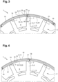
- FIG. 4 illustrates a second embodiment in which some of the air inlet orifices 16 are provided at the level of the connection zones 14, so as to effectively cool each connection zone 14 concerned.
- FIG. 5 illustrates a third embodiment in which the circumferential dimension of the first zone 20 is larger than the circumferential dimension of the second zone 21.
- the ratio of the circumferential dimension of the first zone 20 to the circumferential dimension of the second zone 21 is for example between 1 and 10.
- FIG. 6 illustrates a fourth embodiment in which the sealing means comprise a first labyrinth seal 26 and a second labyrinth 27 located respectively at the first axial end and the second axial end of the channel 15.
- Each labyrinth seal 26, 27 comprises one or more radial annular flanges 27 extending from the internal part 10, interposed axially between one or more radial annular flanges 28 extending from the external part 9, or vice versa.
Landscapes
- Engineering & Computer Science (AREA)
- Mechanical Engineering (AREA)
- General Engineering & Computer Science (AREA)
- Turbine Rotor Nozzle Sealing (AREA)
- Structures Of Non-Positive Displacement Pumps (AREA)
Applications Claiming Priority (2)
| Application Number | Priority Date | Filing Date | Title |
|---|---|---|---|
| FR1908957A FR3099787B1 (fr) | 2019-08-05 | 2019-08-05 | Anneau pour une turbine de turbomachine ou de turbomoteur |
| PCT/FR2020/051433 WO2021023945A1 (fr) | 2019-08-05 | 2020-08-04 | Anneau pour une turbine de turbomachine ou de turbomoteur |
Publications (2)
| Publication Number | Publication Date |
|---|---|
| EP4010565A1 EP4010565A1 (fr) | 2022-06-15 |
| EP4010565B1 true EP4010565B1 (fr) | 2023-10-18 |
Family
ID=69375409
Family Applications (1)
| Application Number | Title | Priority Date | Filing Date |
|---|---|---|---|
| EP20760497.6A Active EP4010565B1 (fr) | 2019-08-05 | 2020-08-04 | Anneau pour une turbine de turbomachine ou de turbomoteur |
Country Status (6)
| Country | Link |
|---|---|
| US (1) | US20220251963A1 (pl) |
| EP (1) | EP4010565B1 (pl) |
| CN (1) | CN114207254B (pl) |
| FR (1) | FR3099787B1 (pl) |
| PL (1) | PL4010565T3 (pl) |
| WO (1) | WO2021023945A1 (pl) |
Families Citing this family (4)
| Publication number | Priority date | Publication date | Assignee | Title |
|---|---|---|---|---|
| US12529316B2 (en) | 2021-06-18 | 2026-01-20 | Rtx Corporation | Bonding method for repair of superalloy article |
| US12055056B2 (en) | 2021-06-18 | 2024-08-06 | Rtx Corporation | Hybrid superalloy article and method of manufacture thereof |
| US12392252B2 (en) | 2021-06-18 | 2025-08-19 | Rtx Corporation | Hybrid bonded configuration for blade outer air seal (BOAS) |
| US12037912B2 (en) | 2021-06-18 | 2024-07-16 | Rtx Corporation | Advanced passive clearance control (APCC) control ring produced by field assisted sintering technology (FAST) |
Family Cites Families (14)
| Publication number | Priority date | Publication date | Assignee | Title |
|---|---|---|---|---|
| JP2659950B2 (ja) * | 1987-03-27 | 1997-09-30 | 株式会社東芝 | ガスタービンシユラウド |
| US5456576A (en) * | 1994-08-31 | 1995-10-10 | United Technologies Corporation | Dynamic control of tip clearance |
| GB9725623D0 (en) * | 1997-12-03 | 2006-09-20 | Rolls Royce Plc | Improvements in or relating to a blade tip clearance system |
| US6116852A (en) * | 1997-12-11 | 2000-09-12 | Pratt & Whitney Canada Corp. | Turbine passive thermal valve for improved tip clearance control |
| GB0228748D0 (en) * | 2002-12-10 | 2003-01-15 | Alstom Switzerland Ltd | Sealing arrangement |
| FR2891300A1 (fr) * | 2005-09-23 | 2007-03-30 | Snecma Sa | Dispositif de controle de jeu dans une turbine a gaz |
| GB0703827D0 (en) * | 2007-02-28 | 2007-04-11 | Rolls Royce Plc | Rotor seal segment |
| DE102009016260A1 (de) * | 2009-04-03 | 2010-10-07 | Fraunhofer-Gesellschaft zur Förderung der angewandten Forschung e.V. | Verfahren beim Schweißen und Bauteil |
| US8753073B2 (en) * | 2010-06-23 | 2014-06-17 | General Electric Company | Turbine shroud sealing apparatus |
| ES2705532T3 (es) * | 2012-10-30 | 2019-03-25 | MTU Aero Engines AG | Anillo de turbina y turbomáquina |
| US10060288B2 (en) * | 2015-10-09 | 2018-08-28 | United Technologies Corporation | Multi-flow cooling passage chamber for gas turbine engine |
| US10100654B2 (en) * | 2015-11-24 | 2018-10-16 | Rolls-Royce North American Technologies Inc. | Impingement tubes for CMC seal segment cooling |
| FR3055146B1 (fr) * | 2016-08-19 | 2020-05-29 | Safran Aircraft Engines | Ensemble d'anneau de turbine |
| US10480337B2 (en) * | 2017-04-18 | 2019-11-19 | Rolls-Royce North American Technologies Inc. | Turbine shroud assembly with multi-piece seals |
-
2019
- 2019-08-05 FR FR1908957A patent/FR3099787B1/fr active Active
-
2020
- 2020-08-04 CN CN202080056482.6A patent/CN114207254B/zh active Active
- 2020-08-04 US US17/630,454 patent/US20220251963A1/en not_active Abandoned
- 2020-08-04 PL PL20760497.6T patent/PL4010565T3/pl unknown
- 2020-08-04 WO PCT/FR2020/051433 patent/WO2021023945A1/fr not_active Ceased
- 2020-08-04 EP EP20760497.6A patent/EP4010565B1/fr active Active
Also Published As
| Publication number | Publication date |
|---|---|
| CN114207254A (zh) | 2022-03-18 |
| US20220251963A1 (en) | 2022-08-11 |
| FR3099787A1 (fr) | 2021-02-12 |
| WO2021023945A1 (fr) | 2021-02-11 |
| EP4010565A1 (fr) | 2022-06-15 |
| FR3099787B1 (fr) | 2021-09-17 |
| PL4010565T3 (pl) | 2024-02-19 |
| CN114207254B (zh) | 2024-09-27 |
Similar Documents
| Publication | Publication Date | Title |
|---|---|---|
| EP4010565A1 (fr) | Anneau pour une turbine de turbomachine ou de turbomoteur | |
| EP3911842B1 (fr) | Ensemble pour une turbomachine | |
| EP4107369B1 (fr) | Aube de turbine comportant trois types d'orifices de refroidissement du bord de fuite | |
| FR3006366A1 (fr) | Roue de turbine dans une turbomachine | |
| WO2020193913A1 (fr) | Aube de turbomachine equipee d'un circuit de refroidissement optimise | |
| EP4409114A1 (fr) | Turbine à gaz haute-pression pour une turbomachine et turbomachine | |
| EP4136326B1 (fr) | Turbine avec anneau d'étanchéité pour une turbomachine | |
| EP3824221B1 (fr) | Ensemble pour une turbomachine | |
| EP4136327B1 (fr) | Dispositif de refroidissement d'un carter de turbine | |
| FR3100560A1 (fr) | Ensemble pour une turbine de turbomachine | |
| FR3092612A1 (fr) | Système de refroidissement d’anneau de retenue axiale d’aubes de turbine pour turbomachine d’aéronef | |
| FR3096394A1 (fr) | Ensemble pour turbomachine | |
| FR3100572A1 (fr) | Secteur d’anneau de turbine | |
| EP4259906A1 (fr) | Ensemble statorique de turbine avec degré de liberté radial entre un distributeur et un anneau d'étanchéité | |
| EP4416379B1 (fr) | Distributeur de turbine comportant un élément annulaire d'étanchéité | |
| EP3976935B1 (fr) | Anneau d'étanchéité pour une roue de turbine de turbomachine | |
| FR3116305A1 (fr) | Arbre de liaison d’un corps haute pression d’une turbomachine | |
| WO2020240129A1 (fr) | Module de turbomachine d'aeronef | |
| FR3093532A1 (fr) | Dispositif de ventilation d’une roue de turbine de turbomachine et/ou de retenue axiale d’aubes d’une telle roue | |
| FR3126442A1 (fr) | Roue aubagée de stator de turbine | |
| FR3113921A1 (fr) | Roue aubagée de turbomachine | |
| FR3152038A1 (fr) | Distributeur, notamment pour une turbine d’une turbomachine d’aéronef | |
| FR3127251A1 (fr) | Refroidissement d’aubes de turbine de turbomachines | |
| FR3161921A1 (fr) | Aubage metallique pour une turbomachine d’aeronef et son procede de fabrication | |
| FR3121469A1 (fr) | Ensemble d’anneau de turbine pour une turbomachine |
Legal Events
| Date | Code | Title | Description |
|---|---|---|---|
| STAA | Information on the status of an ep patent application or granted ep patent |
Free format text: STATUS: UNKNOWN |
|
| STAA | Information on the status of an ep patent application or granted ep patent |
Free format text: STATUS: THE INTERNATIONAL PUBLICATION HAS BEEN MADE |
|
| PUAI | Public reference made under article 153(3) epc to a published international application that has entered the european phase |
Free format text: ORIGINAL CODE: 0009012 |
|
| STAA | Information on the status of an ep patent application or granted ep patent |
Free format text: STATUS: REQUEST FOR EXAMINATION WAS MADE |
|
| 17P | Request for examination filed |
Effective date: 20220207 |
|
| AK | Designated contracting states |
Kind code of ref document: A1 Designated state(s): AL AT BE BG CH CY CZ DE DK EE ES FI FR GB GR HR HU IE IS IT LI LT LU LV MC MK MT NL NO PL PT RO RS SE SI SK SM TR |
|
| DAV | Request for validation of the european patent (deleted) | ||
| DAX | Request for extension of the european patent (deleted) | ||
| GRAP | Despatch of communication of intention to grant a patent |
Free format text: ORIGINAL CODE: EPIDOSNIGR1 |
|
| STAA | Information on the status of an ep patent application or granted ep patent |
Free format text: STATUS: GRANT OF PATENT IS INTENDED |
|
| INTG | Intention to grant announced |
Effective date: 20230626 |
|
| GRAS | Grant fee paid |
Free format text: ORIGINAL CODE: EPIDOSNIGR3 |
|
| GRAA | (expected) grant |
Free format text: ORIGINAL CODE: 0009210 |
|
| STAA | Information on the status of an ep patent application or granted ep patent |
Free format text: STATUS: THE PATENT HAS BEEN GRANTED |
|
| AK | Designated contracting states |
Kind code of ref document: B1 Designated state(s): AL AT BE BG CH CY CZ DE DK EE ES FI FR GB GR HR HU IE IS IT LI LT LU LV MC MK MT NL NO PL PT RO RS SE SI SK SM TR |
|
| REG | Reference to a national code |
Ref country code: GB Ref legal event code: FG4D Free format text: NOT ENGLISH |
|
| REG | Reference to a national code |
Ref country code: CH Ref legal event code: EP |
|
| REG | Reference to a national code |
Ref country code: IE Ref legal event code: FG4D Free format text: LANGUAGE OF EP DOCUMENT: FRENCH |
|
| REG | Reference to a national code |
Ref country code: DE Ref legal event code: R096 Ref document number: 602020019500 Country of ref document: DE |
|
| REG | Reference to a national code |
Ref country code: LT Ref legal event code: MG9D |
|
| REG | Reference to a national code |
Ref country code: NL Ref legal event code: MP Effective date: 20231018 |
|
| REG | Reference to a national code |
Ref country code: AT Ref legal event code: MK05 Ref document number: 1622658 Country of ref document: AT Kind code of ref document: T Effective date: 20231018 |
|
| PG25 | Lapsed in a contracting state [announced via postgrant information from national office to epo] |
Ref country code: NL Free format text: LAPSE BECAUSE OF FAILURE TO SUBMIT A TRANSLATION OF THE DESCRIPTION OR TO PAY THE FEE WITHIN THE PRESCRIBED TIME-LIMIT Effective date: 20231018 |
|
| PG25 | Lapsed in a contracting state [announced via postgrant information from national office to epo] |
Ref country code: GR Free format text: LAPSE BECAUSE OF FAILURE TO SUBMIT A TRANSLATION OF THE DESCRIPTION OR TO PAY THE FEE WITHIN THE PRESCRIBED TIME-LIMIT Effective date: 20240119 |
|
| PG25 | Lapsed in a contracting state [announced via postgrant information from national office to epo] |
Ref country code: IS Free format text: LAPSE BECAUSE OF FAILURE TO SUBMIT A TRANSLATION OF THE DESCRIPTION OR TO PAY THE FEE WITHIN THE PRESCRIBED TIME-LIMIT Effective date: 20240218 |
|
| PG25 | Lapsed in a contracting state [announced via postgrant information from national office to epo] |
Ref country code: LT Free format text: LAPSE BECAUSE OF FAILURE TO SUBMIT A TRANSLATION OF THE DESCRIPTION OR TO PAY THE FEE WITHIN THE PRESCRIBED TIME-LIMIT Effective date: 20231018 |
|
| PG25 | Lapsed in a contracting state [announced via postgrant information from national office to epo] |
Ref country code: AT Free format text: LAPSE BECAUSE OF FAILURE TO SUBMIT A TRANSLATION OF THE DESCRIPTION OR TO PAY THE FEE WITHIN THE PRESCRIBED TIME-LIMIT Effective date: 20231018 |
|
| PG25 | Lapsed in a contracting state [announced via postgrant information from national office to epo] |
Ref country code: ES Free format text: LAPSE BECAUSE OF FAILURE TO SUBMIT A TRANSLATION OF THE DESCRIPTION OR TO PAY THE FEE WITHIN THE PRESCRIBED TIME-LIMIT Effective date: 20231018 |
|
| PG25 | Lapsed in a contracting state [announced via postgrant information from national office to epo] |
Ref country code: LT Free format text: LAPSE BECAUSE OF FAILURE TO SUBMIT A TRANSLATION OF THE DESCRIPTION OR TO PAY THE FEE WITHIN THE PRESCRIBED TIME-LIMIT Effective date: 20231018 Ref country code: IS Free format text: LAPSE BECAUSE OF FAILURE TO SUBMIT A TRANSLATION OF THE DESCRIPTION OR TO PAY THE FEE WITHIN THE PRESCRIBED TIME-LIMIT Effective date: 20240218 Ref country code: GR Free format text: LAPSE BECAUSE OF FAILURE TO SUBMIT A TRANSLATION OF THE DESCRIPTION OR TO PAY THE FEE WITHIN THE PRESCRIBED TIME-LIMIT Effective date: 20240119 Ref country code: ES Free format text: LAPSE BECAUSE OF FAILURE TO SUBMIT A TRANSLATION OF THE DESCRIPTION OR TO PAY THE FEE WITHIN THE PRESCRIBED TIME-LIMIT Effective date: 20231018 Ref country code: BG Free format text: LAPSE BECAUSE OF FAILURE TO SUBMIT A TRANSLATION OF THE DESCRIPTION OR TO PAY THE FEE WITHIN THE PRESCRIBED TIME-LIMIT Effective date: 20240118 Ref country code: AT Free format text: LAPSE BECAUSE OF FAILURE TO SUBMIT A TRANSLATION OF THE DESCRIPTION OR TO PAY THE FEE WITHIN THE PRESCRIBED TIME-LIMIT Effective date: 20231018 Ref country code: PT Free format text: LAPSE BECAUSE OF FAILURE TO SUBMIT A TRANSLATION OF THE DESCRIPTION OR TO PAY THE FEE WITHIN THE PRESCRIBED TIME-LIMIT Effective date: 20240219 |
|
| PG25 | Lapsed in a contracting state [announced via postgrant information from national office to epo] |
Ref country code: SE Free format text: LAPSE BECAUSE OF FAILURE TO SUBMIT A TRANSLATION OF THE DESCRIPTION OR TO PAY THE FEE WITHIN THE PRESCRIBED TIME-LIMIT Effective date: 20231018 Ref country code: RS Free format text: LAPSE BECAUSE OF FAILURE TO SUBMIT A TRANSLATION OF THE DESCRIPTION OR TO PAY THE FEE WITHIN THE PRESCRIBED TIME-LIMIT Effective date: 20231018 Ref country code: NO Free format text: LAPSE BECAUSE OF FAILURE TO SUBMIT A TRANSLATION OF THE DESCRIPTION OR TO PAY THE FEE WITHIN THE PRESCRIBED TIME-LIMIT Effective date: 20240118 Ref country code: LV Free format text: LAPSE BECAUSE OF FAILURE TO SUBMIT A TRANSLATION OF THE DESCRIPTION OR TO PAY THE FEE WITHIN THE PRESCRIBED TIME-LIMIT Effective date: 20231018 Ref country code: HR Free format text: LAPSE BECAUSE OF FAILURE TO SUBMIT A TRANSLATION OF THE DESCRIPTION OR TO PAY THE FEE WITHIN THE PRESCRIBED TIME-LIMIT Effective date: 20231018 |
|
| PG25 | Lapsed in a contracting state [announced via postgrant information from national office to epo] |
Ref country code: DK Free format text: LAPSE BECAUSE OF FAILURE TO SUBMIT A TRANSLATION OF THE DESCRIPTION OR TO PAY THE FEE WITHIN THE PRESCRIBED TIME-LIMIT Effective date: 20231018 |
|
| REG | Reference to a national code |
Ref country code: DE Ref legal event code: R097 Ref document number: 602020019500 Country of ref document: DE |
|
| PG25 | Lapsed in a contracting state [announced via postgrant information from national office to epo] |
Ref country code: SK Free format text: LAPSE BECAUSE OF FAILURE TO SUBMIT A TRANSLATION OF THE DESCRIPTION OR TO PAY THE FEE WITHIN THE PRESCRIBED TIME-LIMIT Effective date: 20231018 |
|
| PG25 | Lapsed in a contracting state [announced via postgrant information from national office to epo] |
Ref country code: SM Free format text: LAPSE BECAUSE OF FAILURE TO SUBMIT A TRANSLATION OF THE DESCRIPTION OR TO PAY THE FEE WITHIN THE PRESCRIBED TIME-LIMIT Effective date: 20231018 Ref country code: SK Free format text: LAPSE BECAUSE OF FAILURE TO SUBMIT A TRANSLATION OF THE DESCRIPTION OR TO PAY THE FEE WITHIN THE PRESCRIBED TIME-LIMIT Effective date: 20231018 Ref country code: RO Free format text: LAPSE BECAUSE OF FAILURE TO SUBMIT A TRANSLATION OF THE DESCRIPTION OR TO PAY THE FEE WITHIN THE PRESCRIBED TIME-LIMIT Effective date: 20231018 Ref country code: EE Free format text: LAPSE BECAUSE OF FAILURE TO SUBMIT A TRANSLATION OF THE DESCRIPTION OR TO PAY THE FEE WITHIN THE PRESCRIBED TIME-LIMIT Effective date: 20231018 Ref country code: DK Free format text: LAPSE BECAUSE OF FAILURE TO SUBMIT A TRANSLATION OF THE DESCRIPTION OR TO PAY THE FEE WITHIN THE PRESCRIBED TIME-LIMIT Effective date: 20231018 |
|
| PLBE | No opposition filed within time limit |
Free format text: ORIGINAL CODE: 0009261 |
|
| STAA | Information on the status of an ep patent application or granted ep patent |
Free format text: STATUS: NO OPPOSITION FILED WITHIN TIME LIMIT |
|
| 26N | No opposition filed |
Effective date: 20240719 |
|
| PG25 | Lapsed in a contracting state [announced via postgrant information from national office to epo] |
Ref country code: SI Free format text: LAPSE BECAUSE OF FAILURE TO SUBMIT A TRANSLATION OF THE DESCRIPTION OR TO PAY THE FEE WITHIN THE PRESCRIBED TIME-LIMIT Effective date: 20231018 |
|
| PG25 | Lapsed in a contracting state [announced via postgrant information from national office to epo] |
Ref country code: SI Free format text: LAPSE BECAUSE OF FAILURE TO SUBMIT A TRANSLATION OF THE DESCRIPTION OR TO PAY THE FEE WITHIN THE PRESCRIBED TIME-LIMIT Effective date: 20231018 |
|
| REG | Reference to a national code |
Ref country code: CH Ref legal event code: PL |
|
| PG25 | Lapsed in a contracting state [announced via postgrant information from national office to epo] |
Ref country code: LU Free format text: LAPSE BECAUSE OF NON-PAYMENT OF DUE FEES Effective date: 20240804 |
|
| PG25 | Lapsed in a contracting state [announced via postgrant information from national office to epo] |
Ref country code: MC Free format text: LAPSE BECAUSE OF FAILURE TO SUBMIT A TRANSLATION OF THE DESCRIPTION OR TO PAY THE FEE WITHIN THE PRESCRIBED TIME-LIMIT Effective date: 20231018 Ref country code: CH Free format text: LAPSE BECAUSE OF NON-PAYMENT OF DUE FEES Effective date: 20240831 |
|
| REG | Reference to a national code |
Ref country code: BE Ref legal event code: MM Effective date: 20240831 |
|
| PG25 | Lapsed in a contracting state [announced via postgrant information from national office to epo] |
Ref country code: BE Free format text: LAPSE BECAUSE OF NON-PAYMENT OF DUE FEES Effective date: 20240831 |
|
| PG25 | Lapsed in a contracting state [announced via postgrant information from national office to epo] |
Ref country code: IE Free format text: LAPSE BECAUSE OF NON-PAYMENT OF DUE FEES Effective date: 20240804 |
|
| PG25 | Lapsed in a contracting state [announced via postgrant information from national office to epo] |
Ref country code: FI Free format text: LAPSE BECAUSE OF FAILURE TO SUBMIT A TRANSLATION OF THE DESCRIPTION OR TO PAY THE FEE WITHIN THE PRESCRIBED TIME-LIMIT Effective date: 20231019 |
|
| PGFP | Annual fee paid to national office [announced via postgrant information from national office to epo] |
Ref country code: DE Payment date: 20250819 Year of fee payment: 6 |
|
| PGFP | Annual fee paid to national office [announced via postgrant information from national office to epo] |
Ref country code: PL Payment date: 20250730 Year of fee payment: 6 Ref country code: IT Payment date: 20250829 Year of fee payment: 6 |
|
| PGFP | Annual fee paid to national office [announced via postgrant information from national office to epo] |
Ref country code: GB Payment date: 20250825 Year of fee payment: 6 |
|
| PGFP | Annual fee paid to national office [announced via postgrant information from national office to epo] |
Ref country code: FR Payment date: 20250827 Year of fee payment: 6 |
|
| PGFP | Annual fee paid to national office [announced via postgrant information from national office to epo] |
Ref country code: CZ Payment date: 20250722 Year of fee payment: 6 |
|
| PG25 | Lapsed in a contracting state [announced via postgrant information from national office to epo] |
Ref country code: CY Free format text: LAPSE BECAUSE OF FAILURE TO SUBMIT A TRANSLATION OF THE DESCRIPTION OR TO PAY THE FEE WITHIN THE PRESCRIBED TIME-LIMIT; INVALID AB INITIO Effective date: 20200804 |
|
| PG25 | Lapsed in a contracting state [announced via postgrant information from national office to epo] |
Ref country code: HU Free format text: LAPSE BECAUSE OF FAILURE TO SUBMIT A TRANSLATION OF THE DESCRIPTION OR TO PAY THE FEE WITHIN THE PRESCRIBED TIME-LIMIT; INVALID AB INITIO Effective date: 20200804 |