EP4010071B1 - Vorrichtung zum aussenden eines magnetfeldes - Google Patents
Vorrichtung zum aussenden eines magnetfeldes Download PDFInfo
- Publication number
- EP4010071B1 EP4010071B1 EP20747434.7A EP20747434A EP4010071B1 EP 4010071 B1 EP4010071 B1 EP 4010071B1 EP 20747434 A EP20747434 A EP 20747434A EP 4010071 B1 EP4010071 B1 EP 4010071B1
- Authority
- EP
- European Patent Office
- Prior art keywords
- antenna
- antennas
- magnetic field
- person
- intensity
- Prior art date
- Legal status (The legal status is an assumption and is not a legal conclusion. Google has not performed a legal analysis and makes no representation as to the accuracy of the status listed.)
- Active
Links
Images


Classifications
-
- A—HUMAN NECESSITIES
- A61—MEDICAL OR VETERINARY SCIENCE; HYGIENE
- A61N—ELECTROTHERAPY; MAGNETOTHERAPY; RADIATION THERAPY; ULTRASOUND THERAPY
- A61N5/00—Radiation therapy
-
- A—HUMAN NECESSITIES
- A61—MEDICAL OR VETERINARY SCIENCE; HYGIENE
- A61N—ELECTROTHERAPY; MAGNETOTHERAPY; RADIATION THERAPY; ULTRASOUND THERAPY
- A61N2/00—Magnetotherapy
- A61N2/02—Magnetotherapy using magnetic fields produced by coils, including single turn loops or electromagnets
-
- A—HUMAN NECESSITIES
- A61—MEDICAL OR VETERINARY SCIENCE; HYGIENE
- A61N—ELECTROTHERAPY; MAGNETOTHERAPY; RADIATION THERAPY; ULTRASOUND THERAPY
- A61N2/00—Magnetotherapy
- A61N2/004—Magnetotherapy specially adapted for a specific therapy
Definitions
- the present invention relates to the general field of devices using electromagnetic waves to act on the metabolism of the human body with a view to inducing physiological changes, in particular to promote sleep, simulate sports practice or treat excess fat.
- the request US 2010/130945 a proposed a method for treating the myocardium in ischemic distress by exposing the myocardium to a coil device emitting an alternating magnetic field of frequency multiple of 16 Hz or multiple of 8 Hz to activate ATP potassium channels in the myocardium.
- devices comprising hexagonal coils have been described in the applications FROM 2010 012 057 And KR 2008 061 463, and Modi Ankita et al. proposed a mathematical model for modeling the magnetic field created by such coils during the Asia-Pacific Conference on Applied Electromagnetics (APACE) on December 11-13, 2016.
- the first antenna Since the current is alternating, the first antenna emits a magnetic field in the opposite direction to that emitted by the second antenna, and the direction of the magnetic field emitted by each antenna alternates according to the frequency of the supply current.
- This device has several advantages. Combining two coils with the direction of winding of the wire reversed, and supplying both coils with an alternating current, makes it possible to emit a global magnetic field that passes through the body of a person on whom the device is placed, during each half-period of the alternating current, and not for a whole period.
- the device of the invention comprises at least two hexagonal antennas.
- hexagonal antenna means a flat dipole antenna of hexagonal shape that emits a magnetic field along a vector perpendicular to its surface.
- the hexagonal antenna is a coil of conductive metal wire wound along the outline of a hexagon. The corners of the hexagon are preferably slightly rounded to avoid the risk of breaking the conductive wire.
- the line of conductive metal is advantageously drawn along the perimeter of the hexagon and is wound over several non-contiguous turns, either inward or outward, so that the turns are not in contact with each other.
- the electrical conductor may comprise a maximum of ten turns in order to ensure both i) user safety (limiting excessive temperature rise that could lead to burns) and ii) sufficient magnetic field intensity.
- Each antenna generates a field whose shape is similar to a horn with a hexagonal cross-section.
- the antennas are preferably copper wire coils.
- the thickness of the metal wire is preferably between 200 and 300 microns.
- hexagonal means a geometric shape comprising six sides.
- the lengths of the sides of the hexagon are preferably equal to within plus or minus 10%.
- the hexagon is preferably a regular hexagon, with all six sides having the same length.
- a particular hexagon comprises a smaller axis connecting two opposite sides and a larger axis connecting two opposite vertices, the smaller axis and the larger axis being perpendicular.
- the device of the invention preferably comprises at least one set of antennas, said set of antennas comprising at least one hexagonal antenna, provided that the device comprises at least the first antenna and the second antenna.
- the device of the invention may comprise at least two sets of antennas, the sets being electrically connected in parallel or in series. It is preferred that the two sets are connected in parallel.
- an antenna assembly preferably comprises at least the first antenna and the second antenna, the first antenna and the second antenna being wound in opposite directions.
- the first antenna and the second antenna may or may not be directly electrically connected.
- the first antenna and the second antenna are part of the same assembly, they are preferably directly electrically connected.
- the antenna assembly comprises more than two antennas
- two antennas that are directly electrically connected have a reverse winding direction.
- the first antenna and the second antenna (which have a reverse winding direction) belong to two separate sets of antennas.
- the antennas may be arranged in subgroups of at least two antennas, the distance between adjacent antennas of a subgroup being less than the distance between two antennas of two different subgroups.
- the insulating support may be formed from at least two sheets of a flexible and thin insulating material, for example two sheets of a polymer material with a thickness of the order of 200-300 microns.
- the antennas are advantageously placed inside the insulating support so as not to come into contact with the body. They can, for example, be placed between the two sheets of insulating material described above.
- the thickness of the insulating support is chosen so that the energy dissipation that occurs during operation of the antennas does not cause an excessive rise in temperature, and does not bother the person. For example, it is around 400-600 microns.
- the insulating support can have different shapes, depending on the part of the body for which the device is intended.
- the support can be shaped like a belt intended to be wrapped around the abdomen.
- the insulating support can alternatively be cut in the form of a strap to fit the contour of the face at the neck.
- the insulating support is in the form of a mat on which the person can lie, or in the form of a bracelet that is wrapped around the hands, arms or ankles.
- the antennas of the device according to the invention emit a magnetic field directed locally towards certain areas of the body to be treated, namely in particular the abdominal belt, the face, the arms, the hands, the thighs, the calves, the ankles and the back.
- This magnetic field makes it possible to simulate a sporting activity, in particular through its action on calcium channels, without any muscular contraction felt by the patient.
- This device not only allows for the reduction of subcutaneous, visceral and intermuscular fat mass, but also helps to combat obesity, combat metabolic syndrome, and significantly increase the chances of medically assisted procreation in infertile people.
- the device when placed on the body of a healthy person, will have a non-therapeutic effect, although it will act on metabolism. It may have an aesthetic effect by reducing subcutaneous fat, or simulate a sporting activity.
- the device In a person with a disease, particularly a person with obesity, the device will have a therapeutic effect on the disease to be treated.
- the main component of the magnetic field emitted by each antenna is not coaxial with the person's spine. Furthermore, the intensity of the magnetic field to which critical areas of the body (heart, lungs, brain) are exposed is very low, so that the use of the device according to the invention presents few risks to the health of the person.
- the power source preferably emits an alternating current whose frequency may be between 10 Hz and 100 Hz, preferably between 40 Hz and 60 Hz. It may be equal to 16 Hz, 32 Hz, 48 Hz, 64 Hz, 80 Hz or 96 Hz, preferably of the order of 50 Hz.
- alternating current it is meant that the value and direction of the current vary as a function of time, preferably according to a sinusoidal function.
- the supply current is an alternating current, it preferably has a voltage of the order of 5 V to 25 V, for example approximately 10 V or 20 V, and an intensity of between 0.3 A and 1.5 A, for example approximately 0.5 A. Indeed, it has been found that a supply current having such characteristics makes it possible to obtain the best results in terms of emitted magnetic field density as well as energy density, avoiding placing the patient in a situation of electrical or thermal risks.
- the antennas are sized to emit a magnetic field with a maximum intensity of 600 microTesla (600 microT, or 6 Gauss). It has been found that applying a magnetic field with an intensity greater than 600 microT can, at high doses, have harmful side effects on the brain and bone cells of the person. Limiting it to such an intensity threshold therefore makes it possible to avoid such risks.
- 600 microTesla 600 microT, or 6 Gauss
- the device of the invention may comprise at least three antennas arranged in a tiling pattern.
- first antenna and the second antenna can be aligned along their longer axis or along their shorter axis.
- a device of the invention may comprise at least two sets of antennas connected in parallel, each set comprising at least two antennas connected in series and comprising at least the first antenna and the second antenna.
- the device may be in the form of a belt or trousers.
- a device of the invention may comprise at least two sets of antennas such that the centers of the antennas of a same set are positioned on a same axis, that the axes of the sets are parallel, and that each set comprises at least the first antenna and the second antenna.
- the device may be in the form of a belt or pants.
- the device is an abdominal belt comprising a rectangular-shaped support and two sets of antennas, the antennas of the same set being powered in series, and the two sets being connected in parallel.
- the current of the power source is preferably an alternating current, so that the antennas of the same winding direction emit a magnetic field of the opposite direction to that emitted by the antennas wound in the opposite direction.
- the antennas of the same set are aligned and the two rows of antennas are placed in a staggered manner.
- the device may comprise a set of antennas connected in series comprising at least the first antenna and the second antenna, the antennas of the set of antennas being distributed in groups of three, and the antennas of a group being arranged in a tiling pattern.
- the device is a face strap intended to be worn around the oval of the face, on the neck.
- the face strap may comprise a curved support and a set of antennas connected in series distributed in three to five groups, each group comprising from one to five antennas, preferably three antennas arranged in a paving pattern, two of them being wound in opposite directions.
- a clockwise wound antenna may be directly connected to a counterclockwise wound antenna.
- the device is a bracelet intended to be worn around the arm or ankle, said bracelet comprising a rectangular-shaped support, the first antenna and the second antenna.
- the device may comprise a third antenna whose center is aligned with that of the other two.
- the device is a strap intended to be worn around the hands, said hand strap comprising a shaped support rectangular and a set of antennas comprising three first antennas and three second antennas arranged along the perimeter of the support.
- the device is intended to be placed around the leg.
- it comprises at least two sets of antennas, each set comprising at least two antennas, preferably two antennas wound in opposite directions, the centers of the antennas of a same set being positioned on a same axis, and the axes of the sets being parallel.
- a particular device comprises three to five sets of antennas intended for the hip, the thigh, the calf and/or the ankle.
- the device may comprise five sets including a set of three antennas at the ankle, a set of four antennas at the calf, two sets at the thigh composed respectively of five antennas and three antennas, and a set at the hip composed of two antennas.
- the device may comprise an antenna array comprising at least five first antennas and at least five second antennas, all fed in series and arranged in a tiling pattern.
- the device is in the form of a mat on which the person can lie down.
- the mat can be placed on the mattress of a bed or on the floor. It can be used as a relaxation or gymnastics mat.
- the mat will preferably be placed so that the antennas are located in the immediate vicinity of the back, more preferably from the lower back to the middle of the back.
- the mat comprises between 10 and 25 antennas, or between 15 and 25 antennas.
- the device is for example in the form of a rectangular mat provided with a single set of antennas comprising at least ten antennas arranged in a paving pattern and powered in series.
- the antennas placed in a paving pattern can define several rows of two or three antennas, the rows being arranged in a staggered pattern.
- the device of the invention may further comprise a control box for the alternating current power supply source of the antennas and at least one magnetic field measurement sensor arranged on the support and connected to said control box.
- a control box for the alternating current power supply source of the antennas and at least one magnetic field measurement sensor arranged on the support and connected to said control box.
- the presence of one or more magnetic field measurement sensors makes it possible to precisely determine the magnetic induction threshold applied to the person. Based on these measurements, an adjustment can therefore be made using the control box.
- the purpose of the devices of the invention is to emit magnetic fields whose characteristics (in particular direction and intensity) aim to reduce the fatty mass present in the targeted parts of the body. This reduction of fatty deposits is made possible thanks to the effect of the magnetic field generated by the device according to the invention which simulates a sporting activity.
- the device comprises i) an insulating support, ii) at least two hexagonal dipole flat antennas which are wound in opposite directions and which emit a magnetic field following a vector perpendicular to its surface, and iii) a source of current supply to the antennas, the current preferably being alternating.
- Each antenna is advantageously sized to expose the person's body to a magnetic field with a maximum intensity of approximately 600 microT.
- the magnetic field should preferably be a maximum of 600 microT on the skin surface and not exceed 1 microT at the center of the body.
- the application of a magnetic field with an intensity greater than 600 microT can, at high doses, have harmful side effects on the person's brain and bone cells. Limiting it to such an intensity threshold of 600 microT therefore makes it possible to avoid such risks.
- the sides of the hexagonal antennas preferably have a length of between 3 cm and 15 cm, and more preferably between 4 cm and 7 cm.
- a side with a length of around 5 cm to 6 cm allows in particular an opening conditioning the rapid decrease in the power of the magnetic field as a function of the depth in the body.
- Antennas in a set can be arranged in different ways, for example, aligned or tessellated. They can be aligned along their shortest axis (in this case, two sides of two adjacent hexagons face each other) or aligned along their longest axis (in this case, the vertices of two adjacent hexagons face each other).
- the antennas in a set preferably have the same shape and dimensions. All antennas in the device preferably have the same shape and dimensions.
- the antennas are preferably arranged such that the smallest distance between one side of a first antenna and one side of a second antenna adjacent to it is between 0.5 cm and 1.5 cm.
- the distance between two adjacent antennas - whether or not they belong to the same set - is preferably between 0.5 cm and 2 cm, more preferably of the order of 1 cm. This distance makes it possible to resolve the problems of intrinsic safety of the device, both in electrical terms if the device were damaged, and in terms of magnetic field and conformity of magnetic powers in limited sections of the body, over sufficient but limited depths.
- the antennas are electrically connected to each other so that the antennas of a single set are powered in series.
- the antenna set preferably comprises at least two antennas connected to each other in series and powered by alternating current.
- the power supply is carried out so that the antennas wound in the same direction belonging to the first set emit a magnetic field following a vector opposite in direction to the vector of the magnetic field emitted by the antennas wound in an opposite direction and belonging to the second set.
- the magnetic field lines coming from the antennas of the same set thus have a maximum intensity at the surface of the skin and decrease in depth in the body.
- the magnetic field generated by such a device allows optimum treatment of the muscular zones located near the hips and at the level of the abdominals (the intensity of the field being concentrated in these zones).
- the device's antennas emit a magnetic field along a vector perpendicular to their surface, with the radiated magnetic field below and above being extremely weak.
- Critical organs of the person such as the heart and lungs are therefore also spared, when the device is placed near them.
- the power source preferably delivers an alternating or pulsed current whose frequency is between 10 Hz and 100 Hz, preferably between 40 and 60 Hz. It may be equal to 16 Hz, 32 Hz, 48 Hz, 64 Hz, 80 Hz or 96 Hz, preferably of the order of 50 Hz.
- the supply current advantageously has a voltage of between 5 V and 25 V, preferably between 5 V and 15 V. It may also be equal to 20 V in certain embodiments.
- the intensity of the supply current of the device is preferably between 0.3 A and 1.5 A, more preferably between 0.5 A and 1.5 A, more preferably equal to 0.5 A.
- the device according to the invention can be applied in contact with different parts of a person's body.
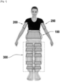
- the figures thus illustrate several devices, namely: a device 100 arranged around the abdominal belt, devices 200 arranged around the arms, and devices 300 arranged around each leg of the person.
- the device 400 of the Figure 5 is designed to be applied to the neck, to reshape the contour of the face.
- the device of the invention can also be placed in contact with a person's back, preferably between the lower and middle of the back, in particular by using the device 500 in the form of a mat of the Figure 6 .
- Device 600 of the Figure 8 is designed to be applied around the hands, and its use has the effect of rejuvenating their appearance, particularly by smoothing the skin.
- FIG. 1 represents a person on whom three devices have been placed: a device 100 in the form of a belt placed around the abdominal belt, two devices 200 in the form of bracelets placed around the arms, and a device 300 in the form of trousers surrounding the legs.
- the device 100 intended to be applied around the abdominal belt comprises a support 102 in the form of a belt made of an insulating material, for example PVC, and which can be closed in the manner of a clothing belt.
- the device 100 comprises two sets of five antennas, the antennas of the same set being connected in series and the two sets being connected in parallel. Each set alternates a counterclockwise wound coil (antenna 104a) and a clockwise wound coil (antenna 104b).
- the centers of the antennas of the same set are aligned along the largest axis of the hexagons, and are spaced apart by a pitch chosen so that the two sets can be placed in cinquecent.
- the smallest distance between an antenna of the first set and an antenna of the second set is preferably from 0.5 cm to 1.5 cm.
- the belt can be of a larger or smaller size, for example that of a blanket or a duvet in which the patient can be placed.
- Each antenna 104a, 104b is a flat hexagonal antenna having an electromagnetic pole at each of its vertices.
- the antennas 104a and 104b of the abdominal belt device 100 are powered by alternating current by means of a power source 106.
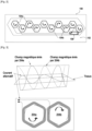
- This device 200 comprises a support 202 made of insulating material, an antenna assembly 204 comprising two hexagonal dipole flat antennas, and a power source 206 for the antenna assembly in alternating current.
- the first antenna 204a is a coil whose winding direction is reversed compared to that of the coil constituting the second antenna 204b.
- the two antennas 204a and 204b are placed side by side along their smallest axis at a distance of a few centimeters from each other.
- the arrangement and size of the antennas make it possible to emit a first magnetic field whose field lines "cross" the arm while being canceled by those of the magnetic field emitted by the second antenna.
- the intensity of the magnetic field emitted by the antennas can be regulated according to the diameter of the person's arm. If the patient has a small diameter arm, the influence of the magnetic field coming from the side of the antenna opposite the wound one is high and in the opposite direction to it. It thus allows to partially cancel the field emitted towards the tissues of the person. On the contrary, if the patient has a large diameter arm, the antenna of the device is arranged almost vertically with respect to this diameter. The antenna then approaches a simple vertical radiating element whose distance between the ends becomes insignificant thanks to the helical shape of its winding.
- the device 300 includes five sets of antennae on the left leg and five sets of antennae on the right leg, making ten sets in total.
- five sets of antennas 304 are wrapped in an insulating support 302, and powered by a current source 306. Each set alternates an antenna wound in one direction and an antenna wound in the opposite direction.
- the insulating support of the device 300 is in one piece in the form of trousers so that all the sets of antennas are fixed relative to each other and can be placed on the patient in a single movement.
- a device within the meaning of the invention is therefore preferably in one piece.
- FIG. 5 represents a face strap intended to be worn around the oval of the face, on the neck.
- the device comprises a set of hexagonal dipole flat antennas.
- the set comprises five groups of three antennas, the antennas in the same group being arranged in a tiling pattern, and each group comprising two antennas wound in opposite directions.
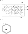
- the device can also be a carpet conforming to that drawn on the Figure 6 on a scale of 1:6.
- the carpet consists of 20 antennas of equal dimensions placed in series in a tiling pattern defining rows of two or three antennas arranged in a staggered pattern.
- a hexagonal antenna forming part of the device of the invention, and whose conductive wire is wound clockwise, may correspond to that shown in Figure 7
- the side of the regular hexagon A can be equal to 5 cm.
- FIG. 8 represents a device 600, which is intended to be worn around the hand.
- the device comprises an antenna assembly 604 comprising six hexagonal dipole flat antennas wrapped in an insulating support 602 and supplied in series with alternating current, two directly connected antennas being wound in opposite directions and emitting a magnetic field of opposite direction.
- the devices of the invention preferably comprise a control box for the alternating current power source of the antennas (not shown). This box control thus makes it possible to control the intensity of the magnetic field emitted for the device's antennas.
- these devices can comprise at least one magnetic field measuring sensor (not shown) arranged on the support and connected to the control box.
- the presence of one or more magnetic field measuring sensors makes it possible to precisely determine the magnetic induction threshold applied to the patient, which corresponds to the optimal intensity of the electric current to be chosen. Based on these measurements, an adjustment can therefore be made using the control box.
- the devices may include a means for automatically adjusting the intensity of the magnetic field emitted for the antennas, depending on the morphology of the users. This is achieved, for example, by compensating for the magnetic permeability of the people that the devices can adjust.
- a dichotomy on the intensity of the magnetic field emitted by the antennas makes it possible to find the ideal operating point. The dichotomy converges when the magnetic field measured on the opposite side of the antenna is equal to, for example, 0.01 Gauss (1 microT).
- the device of the invention is used for emitting a magnetic field penetrating the tissues of at least one part of at least one limb and/or the trunk of a person.
- limb is meant in particular one or both arms and one or both legs, and in particular the calf(s) and the thigh(s), and in particular the upper part of the thigh(s).
- trunk is meant in particular the abdominal area, the lumbar area and the neck.
- the device of the invention may be applied to at least one part of the body selected from the head, face, neck, arms, hands, back, waist, abdomen, lumbar region, hips, thighs, calves and ankles.
- the device may be wrapped around the body, or placed along an axis perpendicular, parallel or inclined relative to the axis of the limb or part of the body concerned.
- the low level of magnetic field required on the surface of the skin between one tenth and a few times the Earth's magnetic field (0.5 Gauss equivalent to 50 microT), allows the implementation of these techniques without risks for the cells of the human body, nor constraints of medical exploitation.
- the device when placed on the body of a healthy person, will have no therapeutic effect, although it will act on metabolism. It may have an aesthetic effect by reducing subcutaneous fat, have a relaxing effect, or simulate a sporting activity.
- the device In a person with a disease, particularly a person with obesity, the device will have a therapeutic effect on the disease to be treated.
- the device can therefore be used in aesthetic treatment methods, therapeutic treatment methods, relaxation methods or methods of simulating a sporting activity. These methods are not part of the claimed subject matter and are described for illustrative purposes only.
- the magnetic field applied to living tissues allows, in particular through its action on the calcium channels of the cells, to simulate a sporting activity without the patient feeling any muscular contraction.
- a method for simulating a sporting activity in a person.
- the description also relates to a method for reducing fat mass, in particular subcutaneous, visceral or intramuscular fat mass, and a method for relaxing or improving the quality of sleep.
- Each of these three methods comprises the implementation of a magnetic field on at least one part of at least one limb of a person by means of a device as described above.
- a method of muscle relaxation or improving sleep quality may comprise applying a magnetic field to at least part of at least one limb and/or the trunk of a person using the device described above.
- the device may take the form of a belt, strap, bracelet, blanket, jumpsuit, pants, pant leg, or mat.
- the method makes it possible to reshape the silhouette or improve the aesthetics of the body of a healthy person, i.e. who does not suffer from any declared disease related to excess fat mass.
- the device can be used for a non-therapeutic method for the aesthetic purpose of reducing visceral or intermuscular fat mass which comprises the implementation of a magnetic field on at least part of at least one limb and/or the trunk of a person by means of a device described above, in particular of a healthy person.
- the device of the invention allows a reduction of visceral or intramuscular fat mass, i.e. at the level of intramuscular adipocytes.
- the reduction of deep fat mass allows a very effective improvement in the aesthetics of the person, for example their silhouette.
- the devices of the prior art do not allow lipolysis to be stimulated deep in the tissues.
- the magnetic field generated by the device of the invention causes the consumption of fat located deep down, in particular under the dermis, in the viscera or in the muscles.
- the magnetic field generated by an antenna on the surface of the skin penetrates the body to a given depth, typically of the order of 2 cm to 10 cm, preferably more than 5 cm, over the entire surface of the antenna. Its intensity decreases with depth.
- the device of the invention it is not necessary to impose a high intensity magnetic field on the surface of the skin to ensure sufficient intensity at depth to activate the biological targets.
- the devices of the prior art do not allow action at such a depth without compromising the safety of the person. There is no diffusion of the magnetic field on an area of the body which must not be exposed to a magnetic field, such as the heart, the brain or the lungs.
- the device can be used for the treatment or prevention of certain diseases or disorders selected from infertility, obesity and metabolic syndrome, and in particular allows the prevention of type 2 diabetes, cardiovascular disorders, and strokes.
- a device as described above may be used in the treatment or prevention of infertility, obesity or metabolic syndrome.
- Metabolic syndrome detected in a person who has not reported any particular symptoms corresponds to a risk of metabolic disorganization higher than that of a so-called healthy individual. Metabolic syndrome can thus be defined as a risk of cardiovascular accident multiplied by three compared to a truly healthy individual. Metabolic syndrome describes a condition that is considered to prefigure several serious diseases including type 2 diabetes (T2D); cardiovascular disorders; and cerebrovascular accidents (CVA).
- T2D type 2 diabetes
- CV disorders cardiovascular disorders
- CVA cerebrovascular accidents
- the device of the invention also makes it possible to prevent or combat obesity, in particular abdominal obesity, and consequently diseases associated with obesity.
- a magnetic field having the intensity and frequency mentioned above also has an activity to stimulate and/or improve oogenesis and spermatogenesis.
- the use of the device of the invention can cause or increase oogenesis and/or spermatogenesis.
- the device therefore makes it possible to treat sterility, increase fertility, and prevent a risk of sterility, in particular when it results from obesity or a high risk of obesity that must be combated.
- the magnetic field generated by the device described above can improve fertility in women or men with a Body Mass Index (BMI) greater than or equal to 30.
- BMI Body Mass Index
- Treatment or prevention of infertility means the stimulation or increase of oogenesis or spermatogenesis, particularly in cases where it is non-existent or insufficient. Treatment of infertility leads to an increase in the pregnancy rate in people undergoing medically assisted procreation.
- the parameters of the antenna dimensions, the intensity and voltage of the electric current supplying the antenna, the duration of the sessions of exposure to the magnetic field and the number of sessions can be adapted according to the desired result.
- a control of the dosage of a magnetic field applied to the patient can be carried out.
- This control of the dosage is in particular carried out by regulating the intensity of the magnetic field.
- This control of the dosage is easily carried out by a variation of the intensity of the electric current supplying the antennas and generating the magnetic field, which is typically between 0.3 A and 1.5 A.
- the dosage of a magnetic field applied to a person can be carried out by placing a magnetic wave sensor in the immediate vicinity of a radiating antenna, said magnetic wave sensor being in communication with a magnetic field control box, said control box communicating with one or more radiating antennas, and the measurement by the control box of the magnetic permeability of the person in order to adapt the magnetic field emitted by the radiating antenna according to an individual profile, in particular by reducing or increasing the intensity of the current. This allows in particular a dosage in intensity and duration of the magnetic field applied to the person.
- a measurement of the response of a person's tissues to contact with a magnetic field may include the variation of the frequencies of the electromagnetic field, preferably between 10 Hz and 10 kHz, with respect to one or more parts of one or more limbs and/or one or more parts of the trunk of a person, and the measurement of the electromagnetic field to estimate the response of the person's tissues.
- the electric field component present in any electromagnetic field, becomes significant from 1 kHz, whereas at 50 Hz the electromagnetic field is mainly characterized by a predominant magnetic field. This electric field then makes it possible to carry out a fine measurement of the magnetic permeability.
- This measurement allows in particular the estimation of fat mass and/or muscle mass in order to adapt the intensity and duration of the magnetic field applied to the person.
- the measurement can be implemented, for example, by passing an alternating current through all the antennas, then successively or simultaneously switching off one or more antennas to measure the electromagnetic field emitted by the remaining antennas.
- the captured electromagnetic field models the magnetic permeability of the person.
- a device in the form of a belt can therefore comprise an electromagnetic sensor arranged diametrically opposite at least one antenna when the belt is positioned on the patient.
- the electromagnetic sensor may be one of the opposite antennas, but used in reception to detect the signal level passing through the patient.
- dielectric permittivity ratios of several orders of magnitude between 10 Hz and 10 kHz, actually measurable between 1 kHz and 10 kHz.
- the presence of a curve slope of fat rather than muscle type makes it possible to evaluate the ratios of tissues to be treated. This information is supplemented by knowledge of the weight and height of the person.
- the response of the person's tissues can also be estimated by varying the frequencies of the magnetic field on one or more parts of one or more limbs and/or parts of the person's trunk.
- the measurement is carried out using a magnetic sensor, for example a Hall effect or magnetoresistive sensor, in particular to determine the maximum and/or optimum power threshold of the magnetic field to be applied to the person.
- the device of the invention makes it possible to emit an alternating magnetic field targeted at certain areas of the body, and in particular located in areas of high muscle and/or viscera density.
- the action of the magnetic field consists of interacting with certain elements involved in the cycles of consumption of fats stored in the body. In particular, the organic cycles linked to calcium are overactivated.
- the invention is illustrated by the following Example.
- the hexagonal antennas of these five devices were all regular hexagons of 5 cm on each side.
- the rectangular dipole flat antennas were all the same size (35 cm long and 3 cm wide).
- the supply current of the devices of the invention and of the devices of the prior art was an alternating current of 50 Hz, 0.5 A and 10 V.
- the intensity of the magnetic field emitted at three different points was measured with a pre-calibrated GM07 reference Gaussmeter, then the average of the three measurements was calculated.
- the value of the magnetic field of the device of the invention is greater than that of the device of the prior art.
- the devices of the invention allow 70% of the body to be covered, whereas the device of the prior art only allows 30% of the body to be covered.
Landscapes
- Health & Medical Sciences (AREA)
- Engineering & Computer Science (AREA)
- Biomedical Technology (AREA)
- Nuclear Medicine, Radiotherapy & Molecular Imaging (AREA)
- Radiology & Medical Imaging (AREA)
- Life Sciences & Earth Sciences (AREA)
- Animal Behavior & Ethology (AREA)
- General Health & Medical Sciences (AREA)
- Public Health (AREA)
- Veterinary Medicine (AREA)
- Pathology (AREA)
- Magnetic Treatment Devices (AREA)
Claims (12)
- Vorrichtung (100; 200; 300; 400; 500; 600) zum Senden eines Magnetfeldes, umfassend:- einen isolierenden Träger (102; 202; 302; 402; 502; 602), der dazu bestimmt ist, mit einem Teil des Körpers einer Person in Kontakt gebracht zu sein,- mindestens eine erste Antenne (104a; 204a) und mindestens eine zweite Antenne (104b; 204b), wobei jede Antenne eine Spule aus einem leitenden Metalldraht ist, der entsprechend dem Verlauf eines Sechsecks gewickelt ist, wobei die Länge seiner Seite zwischen 2 cm und 20 cm liegt,- eine Stromversorgungsquelle (106; 206; 306; 406; 506; 606) für die Antenne,wobei die erste Antenne, die zweite Antenne und die Stromversorgungsquelle fest mit dem isolierenden Träger verbunden sind,wobei der Strom Wechselstrom ist und die erste Antenne und die zweite Antenne in entgegengesetzter Richtung gewickelt sind.
- Vorrichtung nach Anspruch 1, dadurch gekennzeichnet, dass die Länge der Seite des Sechsecks zwischen 3 cm und 15 cm liegt.
- Vorrichtung nach Anspruch 1, dadurch gekennzeichnet, dass sie mindestens drei Antennen umfasst, die gemäß einer Pflasterung angeordnet sind.
- Vorrichtung nach Anspruch 1, dadurch gekennzeichnet, dass die erste Antenne und die zweite Antenne gemäß ihrer größten Achse ausgerichtet sind.
- Vorrichtung nach Anspruch 1, dadurch gekennzeichnet, dass die erste Antenne und die zweite Antenne gemäß ihrer kleinsten Achse ausgerichtet sind.
- Vorrichtung nach Anspruch 1, dadurch gekennzeichnet, dass die erste Antenne und die zweite Antenne direkt elektrisch verbunden sind.
- Vorrichtung nach Anspruch 1, dadurch gekennzeichnet, dass der Körperteil aus der Gruppe ausgewählt ist, die aus Kopf, Gesicht, Hals, Händen, Armen, Rücken, Taille, Bauch, Lendenbereich, Hüften, Oberschenkeln, Waden und Knöcheln besteht.
- Vorrichtung nach Anspruch 1 in Form eines Gürtels oder einer Hose, dadurch gekennzeichnet, dass sie mindestens zwei Antennenanordnungen umfasst, die parallel verbunden sind, dass jede Anordnung mindestens zwei in Reihe geschaltete Antennen umfasst und dass jede Anordnung mindestens die erste Antenne und die zweite Antenne umfasst.
- Vorrichtung nach Anspruch 1 in Form eines Gesichtsriemens, umfassend eine Anordnung von in Reihe geschaltete Antennen, die mindestens die erste Antenne und die zweite Antenne umfasst, wobei die Antennen der Anordnung in Dreiergruppen verteilt sind und die Antennen einer Gruppe pflasterartig angeordnet sind.
- Vorrichtung nach Anspruch 1, dadurch gekennzeichnet, dass sie in Form einer rechteckigen Matte vorliegt, auf der die Person liegen kann, und dass sie eine Antennenanordnung umfasst, die mindestens fünf erste Antennen und mindestens fünf zweite Antennen umfasst, die alle in Reihe versorgt werden und pflasterartig angeordnet sind.
- Vorrichtung nach Anspruch 1, dadurch gekennzeichnet, dass sie in Form eines Riemens vorliegt, der dazu bestimmt ist, um die Hände getragen zu werden, wobei der Handriemen einen rechteckigen Träger und eine Antennenanordnung umfasst, die drei erste Antennen und drei zweite Antennen umfasst, die gemäß dem Umfang des Trägers angeordnet sind, wobei sich die erste Antenne mit der zweiten Antenne in der Anordnung abwechselt.
- Vorrichtung nach Anspruch 1, dadurch gekennzeichnet, dass sie in Form eines Armbands vorliegt, das dazu bestimmt ist, um den Arm oder den Knöchel getragen zu werden, wobei das Armband einen rechteckigen Träger, die erste Antenne und die zweite Antenne umfasst.
Applications Claiming Priority (2)
| Application Number | Priority Date | Filing Date | Title |
|---|---|---|---|
| FR1908980A FR3099705B1 (fr) | 2019-08-05 | 2019-08-05 | Dispositif pour l’émission d’un champ magnétique |
| PCT/EP2020/071926 WO2021023749A1 (fr) | 2019-08-05 | 2020-08-04 | Dispositif pour l'émission d'un champ magnétique |
Publications (3)
| Publication Number | Publication Date |
|---|---|
| EP4010071A1 EP4010071A1 (de) | 2022-06-15 |
| EP4010071B1 true EP4010071B1 (de) | 2025-04-16 |
| EP4010071C0 EP4010071C0 (de) | 2025-04-16 |
Family
ID=70008569
Family Applications (1)
| Application Number | Title | Priority Date | Filing Date |
|---|---|---|---|
| EP20747434.7A Active EP4010071B1 (de) | 2019-08-05 | 2020-08-04 | Vorrichtung zum aussenden eines magnetfeldes |
Country Status (6)
| Country | Link |
|---|---|
| US (1) | US20220331603A1 (de) |
| EP (1) | EP4010071B1 (de) |
| CN (2) | CN111714778A (de) |
| CA (1) | CA3150176A1 (de) |
| FR (1) | FR3099705B1 (de) |
| WO (1) | WO2021023749A1 (de) |
Families Citing this family (4)
| Publication number | Priority date | Publication date | Assignee | Title |
|---|---|---|---|---|
| FR3099705B1 (fr) * | 2019-08-05 | 2024-10-04 | Biopass | Dispositif pour l’émission d’un champ magnétique |
| KR200498115Y1 (ko) | 2020-05-04 | 2024-07-03 | 비티엘 헬쓰케어 테크놀로지스 에이.에스. | 환자의 미용 시술을 위한 디바이스 |
| US11878167B2 (en) | 2020-05-04 | 2024-01-23 | Btl Healthcare Technologies A.S. | Device and method for unattended treatment of a patient |
| KR102829685B1 (ko) * | 2021-12-22 | 2025-07-04 | 주식회사 루트로닉 | 자기장 펄스를 이용한 근육 자극 장치, 그 제어방법 |
Family Cites Families (16)
| Publication number | Priority date | Publication date | Assignee | Title |
|---|---|---|---|---|
| US6561968B1 (en) * | 1999-08-31 | 2003-05-13 | Biofields Aps | Method and an apparatus for stimulating/ modulating biochemical processes using pulsed electromagnetic fields |
| FR2855415B1 (fr) | 2003-05-28 | 2006-01-06 | H C A Sa | Dispositif electrique pour la reduction des surcharges adipeuses |
| DE102004006192B4 (de) * | 2004-02-06 | 2008-11-06 | Axel Muntermann | Vorrichtung zur Behandlung mit Magnetfeldern |
| US8169185B2 (en) * | 2006-01-31 | 2012-05-01 | Mojo Mobility, Inc. | System and method for inductive charging of portable devices |
| FR2906727A1 (fr) | 2006-10-06 | 2008-04-11 | H C A Sa | "procede et appareil pour la reduction des surcharges adipeuses". |
| WO2008053482A2 (en) * | 2006-11-02 | 2008-05-08 | Shlomo Laniado | Application of magnetic field to treat tissue |
| KR100846091B1 (ko) * | 2006-12-28 | 2008-07-14 | 김휘영 | 밴드형 자기치료기 |
| US20100099942A1 (en) * | 2008-10-20 | 2010-04-22 | Lucas Portelli | Method and apparatus for electromagnetic human and animal immune stimulation and/or repair systems activation |
| DE202010012057U1 (de) * | 2010-08-31 | 2011-08-12 | Egon Tech | System zur Magnetstimulation, insbesondere zum Schutz gegen externe ZNS-schädigende EMF-Signale, (BABS-I-Biophysical Anti Brainmanipulation System-Integration) |
| DE102010041649A1 (de) * | 2010-09-29 | 2012-03-29 | Zimmer Medizinsysteme Gmbh | Elektromedizinische Vorrichtung zum nicht-invasiven Reduzieren oder Entfernen von subkutanem Fettgewebe |
| PT2665516E (pt) | 2011-01-21 | 2015-11-17 | Cosmosoft | Dispositivo para emitir um campo magnético |
| DE102013014913B4 (de) * | 2013-09-03 | 2017-06-08 | QRS International AG | Magnetfeldapplikator zur Magnetstimulation von Körpergewebe |
| EP3119473A1 (de) * | 2014-03-17 | 2017-01-25 | The United States of America, as represented by The Secretary, Department of Health and Human Services | System mit elektromagnetfeldgenerator mit spulen zur behandlung von tumoren und verfahren zur gewebebehandlung |
| US9550067B1 (en) * | 2015-10-23 | 2017-01-24 | Zygood, Llc | Shoe-shaped magnetic coil system for the treatment of foot pain |
| DE102018004783B4 (de) * | 2018-06-15 | 2020-08-06 | George-Glad Moroianu | Kurzwellen Draht Multibeam |
| FR3099705B1 (fr) * | 2019-08-05 | 2024-10-04 | Biopass | Dispositif pour l’émission d’un champ magnétique |
-
2019
- 2019-08-05 FR FR1908980A patent/FR3099705B1/fr active Active
- 2019-09-06 CN CN201910841226.7A patent/CN111714778A/zh active Pending
- 2019-09-06 CN CN201921478226.7U patent/CN211634914U/zh active Active
-
2020
- 2020-08-04 EP EP20747434.7A patent/EP4010071B1/de active Active
- 2020-08-04 US US17/633,109 patent/US20220331603A1/en active Pending
- 2020-08-04 WO PCT/EP2020/071926 patent/WO2021023749A1/fr not_active Ceased
- 2020-08-04 CA CA3150176A patent/CA3150176A1/fr active Pending
Also Published As
| Publication number | Publication date |
|---|---|
| CA3150176A1 (fr) | 2021-02-11 |
| CN111714778A (zh) | 2020-09-29 |
| US20220331603A1 (en) | 2022-10-20 |
| WO2021023749A1 (fr) | 2021-02-11 |
| EP4010071A1 (de) | 2022-06-15 |
| FR3099705B1 (fr) | 2024-10-04 |
| CN211634914U (zh) | 2020-10-09 |
| FR3099705A1 (fr) | 2021-02-12 |
| EP4010071C0 (de) | 2025-04-16 |
Similar Documents
| Publication | Publication Date | Title |
|---|---|---|
| EP4010071B1 (de) | Vorrichtung zum aussenden eines magnetfeldes | |
| EP2665516B1 (de) | Vorrichtung zum aussenden eines magnetfeldes | |
| CN102300602B (zh) | 用于刺激盆底肌的方法和装置 | |
| US9849302B1 (en) | Three-coil magnetic pulsations system for the treatment of foot pain | |
| FR2970656A1 (fr) | Methode pour la reduction de la masse graisseuse viscerale ou intramusculaire | |
| US9597225B1 (en) | Non-invasive thermal wrap method for inducing calorie burning and weight loss | |
| Valli et al. | Effects of low intensity electrical stimulation on quadriceps muscle voluntary maximal strength | |
| JP5102092B2 (ja) | 痩身トリートメント装置 | |
| Duncan | Combination treatment for buttock and abdominal remodeling and skin improvement using HIFEM procedure and simultaneous delivery of radiofrequency and targeted pressure energy | |
| Katz | MRI assessment of arm and calf muscle toning with high-intensity focused electromagnetic technology: case study | |
| Busso et al. | High-intensity focused electromagnetic (HIFEM) field therapy used for non-invasive buttock augmentation and lifting: feasibility study | |
| KR102293392B1 (ko) | 3d 전기장을 형성하는 전기 자극장치 및 이를 이용한 골반저근의 강화방법 | |
| Liu et al. | Interface pressure and cutaneous hemoglobin and oxygenation changes under ischial tuberosities during sacral nerve root stimulation in spinal cord injury | |
| US9037269B2 (en) | Applicator head and method for treatment of pain by transcutaneous electrical nerve stimulation | |
| FR2493154A1 (fr) | Procede et installation de stimulation respiratoire | |
| TWM360039U (en) | Clothing with functions of acupuncture, massage, and hot compress | |
| Katz | An overview of HIFEM technology in body contouring | |
| CN114983665A (zh) | 频谱按摩护腰 | |
| FR3140551A1 (fr) | Machine et procede pour le traitement de la graisse viscerale | |
| NL1021021C2 (nl) | Massage-inrichting. | |
| US8874223B2 (en) | Mitigation of pressure ulcers using electrical stimulation | |
| FR2970655A1 (fr) | Dispositif pour la reduction des surcharges adipeuses | |
| CN110545881A (zh) | 一种用于多功能磁疗的止痛垫 | |
| EP4467188A1 (de) | Magnetfeldapplikator für füsse | |
| FR2847803A1 (fr) | Ceinture munie d'organes de stimulation pour le traitement du ronflement et/ou du syndrome d'apnee du sommeil |
Legal Events
| Date | Code | Title | Description |
|---|---|---|---|
| STAA | Information on the status of an ep patent application or granted ep patent |
Free format text: STATUS: UNKNOWN |
|
| STAA | Information on the status of an ep patent application or granted ep patent |
Free format text: STATUS: THE INTERNATIONAL PUBLICATION HAS BEEN MADE |
|
| PUAI | Public reference made under article 153(3) epc to a published international application that has entered the european phase |
Free format text: ORIGINAL CODE: 0009012 |
|
| STAA | Information on the status of an ep patent application or granted ep patent |
Free format text: STATUS: REQUEST FOR EXAMINATION WAS MADE |
|
| 17P | Request for examination filed |
Effective date: 20220203 |
|
| AK | Designated contracting states |
Kind code of ref document: A1 Designated state(s): AL AT BE BG CH CY CZ DE DK EE ES FI FR GB GR HR HU IE IS IT LI LT LU LV MC MK MT NL NO PL PT RO RS SE SI SK SM TR |
|
| DAV | Request for validation of the european patent (deleted) | ||
| DAX | Request for extension of the european patent (deleted) | ||
| P01 | Opt-out of the competence of the unified patent court (upc) registered |
Effective date: 20230512 |
|
| RAP1 | Party data changed (applicant data changed or rights of an application transferred) |
Owner name: COSMOSOFT |
|
| GRAP | Despatch of communication of intention to grant a patent |
Free format text: ORIGINAL CODE: EPIDOSNIGR1 |
|
| STAA | Information on the status of an ep patent application or granted ep patent |
Free format text: STATUS: GRANT OF PATENT IS INTENDED |
|
| INTG | Intention to grant announced |
Effective date: 20240913 |
|
| GRAS | Grant fee paid |
Free format text: ORIGINAL CODE: EPIDOSNIGR3 |
|
| GRAA | (expected) grant |
Free format text: ORIGINAL CODE: 0009210 |
|
| STAA | Information on the status of an ep patent application or granted ep patent |
Free format text: STATUS: THE PATENT HAS BEEN GRANTED |
|
| AK | Designated contracting states |
Kind code of ref document: B1 Designated state(s): AL AT BE BG CH CY CZ DE DK EE ES FI FR GB GR HR HU IE IS IT LI LT LU LV MC MK MT NL NO PL PT RO RS SE SI SK SM TR |
|
| REG | Reference to a national code |
Ref country code: GB Ref legal event code: FG4D Free format text: NOT ENGLISH |
|
| REG | Reference to a national code |
Ref country code: CH Ref legal event code: EP |
|
| REG | Reference to a national code |
Ref country code: IE Ref legal event code: FG4D Free format text: LANGUAGE OF EP DOCUMENT: FRENCH |
|
| U01 | Request for unitary effect filed |
Effective date: 20250416 |
|
| U07 | Unitary effect registered |
Designated state(s): AT BE BG DE DK EE FI FR IT LT LU LV MT NL PT RO SE SI Effective date: 20250424 |
|
| P04 | Withdrawal of opt-out of the competence of the unified patent court (upc) registered |
Free format text: CASE NUMBER: APP_18936/2025 Effective date: 20250418 |
|
| U20 | Renewal fee for the european patent with unitary effect paid |
Year of fee payment: 6 Effective date: 20250624 |
|
| PG25 | Lapsed in a contracting state [announced via postgrant information from national office to epo] |
Ref country code: ES Free format text: LAPSE BECAUSE OF FAILURE TO SUBMIT A TRANSLATION OF THE DESCRIPTION OR TO PAY THE FEE WITHIN THE PRESCRIBED TIME-LIMIT Effective date: 20250416 |
|
| PG25 | Lapsed in a contracting state [announced via postgrant information from national office to epo] |
Ref country code: NO Free format text: LAPSE BECAUSE OF FAILURE TO SUBMIT A TRANSLATION OF THE DESCRIPTION OR TO PAY THE FEE WITHIN THE PRESCRIBED TIME-LIMIT Effective date: 20250716 Ref country code: GR Free format text: LAPSE BECAUSE OF FAILURE TO SUBMIT A TRANSLATION OF THE DESCRIPTION OR TO PAY THE FEE WITHIN THE PRESCRIBED TIME-LIMIT Effective date: 20250717 |
|
| PG25 | Lapsed in a contracting state [announced via postgrant information from national office to epo] |
Ref country code: PL Free format text: LAPSE BECAUSE OF FAILURE TO SUBMIT A TRANSLATION OF THE DESCRIPTION OR TO PAY THE FEE WITHIN THE PRESCRIBED TIME-LIMIT Effective date: 20250416 |
|
| PG25 | Lapsed in a contracting state [announced via postgrant information from national office to epo] |
Ref country code: HR Free format text: LAPSE BECAUSE OF FAILURE TO SUBMIT A TRANSLATION OF THE DESCRIPTION OR TO PAY THE FEE WITHIN THE PRESCRIBED TIME-LIMIT Effective date: 20250416 |
|
| PG25 | Lapsed in a contracting state [announced via postgrant information from national office to epo] |
Ref country code: RS Free format text: LAPSE BECAUSE OF FAILURE TO SUBMIT A TRANSLATION OF THE DESCRIPTION OR TO PAY THE FEE WITHIN THE PRESCRIBED TIME-LIMIT Effective date: 20250716 |
|
| PG25 | Lapsed in a contracting state [announced via postgrant information from national office to epo] |
Ref country code: IS Free format text: LAPSE BECAUSE OF FAILURE TO SUBMIT A TRANSLATION OF THE DESCRIPTION OR TO PAY THE FEE WITHIN THE PRESCRIBED TIME-LIMIT Effective date: 20250816 |