EP4009516A1 - Hybridstromerzeugungssystem - Google Patents
Hybridstromerzeugungssystem Download PDFInfo
- Publication number
- EP4009516A1 EP4009516A1 EP20848498.0A EP20848498A EP4009516A1 EP 4009516 A1 EP4009516 A1 EP 4009516A1 EP 20848498 A EP20848498 A EP 20848498A EP 4009516 A1 EP4009516 A1 EP 4009516A1
- Authority
- EP
- European Patent Office
- Prior art keywords
- wind
- power generation
- control unit
- collecting duct
- recollecting
- Prior art date
- Legal status (The legal status is an assumption and is not a legal conclusion. Google has not performed a legal analysis and makes no representation as to the accuracy of the status listed.)
- Pending
Links
- 238000010248 power generation Methods 0.000 title claims abstract description 132
- 230000001939 inductive effect Effects 0.000 claims abstract description 63
- 230000001965 increasing effect Effects 0.000 claims abstract description 15
- 238000001514 detection method Methods 0.000 claims abstract description 10
- 238000005516 engineering process Methods 0.000 claims abstract description 5
- 238000004891 communication Methods 0.000 claims description 11
- 238000007599 discharging Methods 0.000 claims description 6
- 239000000779 smoke Substances 0.000 claims description 5
- 238000000034 method Methods 0.000 claims description 4
- 230000015556 catabolic process Effects 0.000 abstract description 8
- 238000013473 artificial intelligence Methods 0.000 abstract description 3
- 230000005611 electricity Effects 0.000 description 8
- 238000010586 diagram Methods 0.000 description 6
- 230000002265 prevention Effects 0.000 description 6
- 229910000831 Steel Inorganic materials 0.000 description 3
- 239000002803 fossil fuel Substances 0.000 description 3
- 238000012545 processing Methods 0.000 description 3
- 239000010959 steel Substances 0.000 description 3
- RZVHIXYEVGDQDX-UHFFFAOYSA-N 9,10-anthraquinone Chemical compound C1=CC=C2C(=O)C3=CC=CC=C3C(=O)C2=C1 RZVHIXYEVGDQDX-UHFFFAOYSA-N 0.000 description 2
- 230000002411 adverse Effects 0.000 description 2
- ZZUFCTLCJUWOSV-UHFFFAOYSA-N furosemide Chemical compound C1=C(Cl)C(S(=O)(=O)N)=CC(C(O)=O)=C1NCC1=CC=CO1 ZZUFCTLCJUWOSV-UHFFFAOYSA-N 0.000 description 2
- 238000009434 installation Methods 0.000 description 2
- 230000002829 reductive effect Effects 0.000 description 2
- 230000002441 reversible effect Effects 0.000 description 2
- 238000007664 blowing Methods 0.000 description 1
- 239000003245 coal Substances 0.000 description 1
- 230000003247 decreasing effect Effects 0.000 description 1
- 230000000779 depleting effect Effects 0.000 description 1
- 230000003467 diminishing effect Effects 0.000 description 1
- 230000000694 effects Effects 0.000 description 1
- 238000004146 energy storage Methods 0.000 description 1
- 238000003912 environmental pollution Methods 0.000 description 1
- 230000000670 limiting effect Effects 0.000 description 1
- 230000007257 malfunction Effects 0.000 description 1
- 238000005259 measurement Methods 0.000 description 1
- 238000012986 modification Methods 0.000 description 1
- 230000004048 modification Effects 0.000 description 1
- 238000012544 monitoring process Methods 0.000 description 1
- 230000005855 radiation Effects 0.000 description 1
- 230000035939 shock Effects 0.000 description 1
- 239000002699 waste material Substances 0.000 description 1
Images


Classifications
-
- F—MECHANICAL ENGINEERING; LIGHTING; HEATING; WEAPONS; BLASTING
- F03—MACHINES OR ENGINES FOR LIQUIDS; WIND, SPRING, OR WEIGHT MOTORS; PRODUCING MECHANICAL POWER OR A REACTIVE PROPULSIVE THRUST, NOT OTHERWISE PROVIDED FOR
- F03D—WIND MOTORS
- F03D17/00—Monitoring or testing of wind motors, e.g. diagnostics
-
- F—MECHANICAL ENGINEERING; LIGHTING; HEATING; WEAPONS; BLASTING
- F03—MACHINES OR ENGINES FOR LIQUIDS; WIND, SPRING, OR WEIGHT MOTORS; PRODUCING MECHANICAL POWER OR A REACTIVE PROPULSIVE THRUST, NOT OTHERWISE PROVIDED FOR
- F03D—WIND MOTORS
- F03D3/00—Wind motors with rotation axis substantially perpendicular to the air flow entering the rotor
- F03D3/005—Wind motors with rotation axis substantially perpendicular to the air flow entering the rotor the axis being vertical
-
- F—MECHANICAL ENGINEERING; LIGHTING; HEATING; WEAPONS; BLASTING
- F03—MACHINES OR ENGINES FOR LIQUIDS; WIND, SPRING, OR WEIGHT MOTORS; PRODUCING MECHANICAL POWER OR A REACTIVE PROPULSIVE THRUST, NOT OTHERWISE PROVIDED FOR
- F03D—WIND MOTORS
- F03D3/00—Wind motors with rotation axis substantially perpendicular to the air flow entering the rotor
- F03D3/04—Wind motors with rotation axis substantially perpendicular to the air flow entering the rotor having stationary wind-guiding means, e.g. with shrouds or channels
- F03D3/0427—Wind motors with rotation axis substantially perpendicular to the air flow entering the rotor having stationary wind-guiding means, e.g. with shrouds or channels with converging inlets, i.e. the guiding means intercepting an area greater than the effective rotor area
-
- F—MECHANICAL ENGINEERING; LIGHTING; HEATING; WEAPONS; BLASTING
- F03—MACHINES OR ENGINES FOR LIQUIDS; WIND, SPRING, OR WEIGHT MOTORS; PRODUCING MECHANICAL POWER OR A REACTIVE PROPULSIVE THRUST, NOT OTHERWISE PROVIDED FOR
- F03D—WIND MOTORS
- F03D9/00—Adaptations of wind motors for special use; Combinations of wind motors with apparatus driven thereby; Wind motors specially adapted for installation in particular locations
- F03D9/007—Adaptations of wind motors for special use; Combinations of wind motors with apparatus driven thereby; Wind motors specially adapted for installation in particular locations the wind motor being combined with means for converting solar radiation into useful energy
-
- F—MECHANICAL ENGINEERING; LIGHTING; HEATING; WEAPONS; BLASTING
- F03—MACHINES OR ENGINES FOR LIQUIDS; WIND, SPRING, OR WEIGHT MOTORS; PRODUCING MECHANICAL POWER OR A REACTIVE PROPULSIVE THRUST, NOT OTHERWISE PROVIDED FOR
- F03D—WIND MOTORS
- F03D9/00—Adaptations of wind motors for special use; Combinations of wind motors with apparatus driven thereby; Wind motors specially adapted for installation in particular locations
- F03D9/10—Combinations of wind motors with apparatus storing energy
- F03D9/11—Combinations of wind motors with apparatus storing energy storing electrical energy
-
- G—PHYSICS
- G08—SIGNALLING
- G08B—SIGNALLING OR CALLING SYSTEMS; ORDER TELEGRAPHS; ALARM SYSTEMS
- G08B17/00—Fire alarms; Alarms responsive to explosion
- G08B17/06—Electric actuation of the alarm, e.g. using a thermally-operated switch
-
- G—PHYSICS
- G08—SIGNALLING
- G08B—SIGNALLING OR CALLING SYSTEMS; ORDER TELEGRAPHS; ALARM SYSTEMS
- G08B21/00—Alarms responsive to a single specified undesired or abnormal condition and not otherwise provided for
- G08B21/18—Status alarms
- G08B21/185—Electrical failure alarms
-
- G—PHYSICS
- G08—SIGNALLING
- G08C—TRANSMISSION SYSTEMS FOR MEASURED VALUES, CONTROL OR SIMILAR SIGNALS
- G08C17/00—Arrangements for transmitting signals characterised by the use of a wireless electrical link
- G08C17/02—Arrangements for transmitting signals characterised by the use of a wireless electrical link using a radio link
-
- G—PHYSICS
- G08—SIGNALLING
- G08C—TRANSMISSION SYSTEMS FOR MEASURED VALUES, CONTROL OR SIMILAR SIGNALS
- G08C19/00—Electric signal transmission systems
- G08C19/02—Electric signal transmission systems in which the signal transmitted is magnitude of current or voltage
-
- H—ELECTRICITY
- H02—GENERATION; CONVERSION OR DISTRIBUTION OF ELECTRIC POWER
- H02J—CIRCUIT ARRANGEMENTS OR SYSTEMS FOR SUPPLYING OR DISTRIBUTING ELECTRIC POWER; SYSTEMS FOR STORING ELECTRIC ENERGY
- H02J7/00—Circuit arrangements for charging or depolarising batteries or for supplying loads from batteries
- H02J7/34—Parallel operation in networks using both storage and other dc sources, e.g. providing buffering
- H02J7/35—Parallel operation in networks using both storage and other dc sources, e.g. providing buffering with light sensitive cells
-
- H—ELECTRICITY
- H02—GENERATION; CONVERSION OR DISTRIBUTION OF ELECTRIC POWER
- H02S—GENERATION OF ELECTRIC POWER BY CONVERSION OF INFRARED RADIATION, VISIBLE LIGHT OR ULTRAVIOLET LIGHT, e.g. USING PHOTOVOLTAIC [PV] MODULES
- H02S10/00—PV power plants; Combinations of PV energy systems with other systems for the generation of electric power
- H02S10/10—PV power plants; Combinations of PV energy systems with other systems for the generation of electric power including a supplementary source of electric power, e.g. hybrid diesel-PV energy systems
- H02S10/12—Hybrid wind-PV energy systems
-
- H—ELECTRICITY
- H02—GENERATION; CONVERSION OR DISTRIBUTION OF ELECTRIC POWER
- H02S—GENERATION OF ELECTRIC POWER BY CONVERSION OF INFRARED RADIATION, VISIBLE LIGHT OR ULTRAVIOLET LIGHT, e.g. USING PHOTOVOLTAIC [PV] MODULES
- H02S10/00—PV power plants; Combinations of PV energy systems with other systems for the generation of electric power
- H02S10/20—Systems characterised by their energy storage means
-
- H—ELECTRICITY
- H02—GENERATION; CONVERSION OR DISTRIBUTION OF ELECTRIC POWER
- H02S—GENERATION OF ELECTRIC POWER BY CONVERSION OF INFRARED RADIATION, VISIBLE LIGHT OR ULTRAVIOLET LIGHT, e.g. USING PHOTOVOLTAIC [PV] MODULES
- H02S50/00—Monitoring or testing of PV systems, e.g. load balancing or fault identification
-
- F—MECHANICAL ENGINEERING; LIGHTING; HEATING; WEAPONS; BLASTING
- F05—INDEXING SCHEMES RELATING TO ENGINES OR PUMPS IN VARIOUS SUBCLASSES OF CLASSES F01-F04
- F05B—INDEXING SCHEME RELATING TO WIND, SPRING, WEIGHT, INERTIA OR LIKE MOTORS, TO MACHINES OR ENGINES FOR LIQUIDS COVERED BY SUBCLASSES F03B, F03D AND F03G
- F05B2220/00—Application
- F05B2220/70—Application in combination with
- F05B2220/708—Photoelectric means, i.e. photovoltaic or solar cells
-
- F—MECHANICAL ENGINEERING; LIGHTING; HEATING; WEAPONS; BLASTING
- F05—INDEXING SCHEMES RELATING TO ENGINES OR PUMPS IN VARIOUS SUBCLASSES OF CLASSES F01-F04
- F05B—INDEXING SCHEME RELATING TO WIND, SPRING, WEIGHT, INERTIA OR LIKE MOTORS, TO MACHINES OR ENGINES FOR LIQUIDS COVERED BY SUBCLASSES F03B, F03D AND F03G
- F05B2240/00—Components
- F05B2240/10—Stators
- F05B2240/13—Stators to collect or cause flow towards or away from turbines
-
- F—MECHANICAL ENGINEERING; LIGHTING; HEATING; WEAPONS; BLASTING
- F05—INDEXING SCHEMES RELATING TO ENGINES OR PUMPS IN VARIOUS SUBCLASSES OF CLASSES F01-F04
- F05B—INDEXING SCHEME RELATING TO WIND, SPRING, WEIGHT, INERTIA OR LIKE MOTORS, TO MACHINES OR ENGINES FOR LIQUIDS COVERED BY SUBCLASSES F03B, F03D AND F03G
- F05B2240/00—Components
- F05B2240/20—Rotors
- F05B2240/21—Rotors for wind turbines
- F05B2240/211—Rotors for wind turbines with vertical axis
-
- F—MECHANICAL ENGINEERING; LIGHTING; HEATING; WEAPONS; BLASTING
- F05—INDEXING SCHEMES RELATING TO ENGINES OR PUMPS IN VARIOUS SUBCLASSES OF CLASSES F01-F04
- F05B—INDEXING SCHEME RELATING TO WIND, SPRING, WEIGHT, INERTIA OR LIKE MOTORS, TO MACHINES OR ENGINES FOR LIQUIDS COVERED BY SUBCLASSES F03B, F03D AND F03G
- F05B2270/00—Control
- F05B2270/30—Control parameters, e.g. input parameters
- F05B2270/32—Wind speeds
-
- H—ELECTRICITY
- H02—GENERATION; CONVERSION OR DISTRIBUTION OF ELECTRIC POWER
- H02J—CIRCUIT ARRANGEMENTS OR SYSTEMS FOR SUPPLYING OR DISTRIBUTING ELECTRIC POWER; SYSTEMS FOR STORING ELECTRIC ENERGY
- H02J7/00—Circuit arrangements for charging or depolarising batteries or for supplying loads from batteries
- H02J7/0013—Circuit arrangements for charging or depolarising batteries or for supplying loads from batteries acting upon several batteries simultaneously or sequentially
- H02J7/0014—Circuits for equalisation of charge between batteries
-
- H—ELECTRICITY
- H02—GENERATION; CONVERSION OR DISTRIBUTION OF ELECTRIC POWER
- H02J—CIRCUIT ARRANGEMENTS OR SYSTEMS FOR SUPPLYING OR DISTRIBUTING ELECTRIC POWER; SYSTEMS FOR STORING ELECTRIC ENERGY
- H02J7/00—Circuit arrangements for charging or depolarising batteries or for supplying loads from batteries
- H02J7/0047—Circuit arrangements for charging or depolarising batteries or for supplying loads from batteries with monitoring or indicating devices or circuits
- H02J7/0048—Detection of remaining charge capacity or state of charge [SOC]
-
- Y—GENERAL TAGGING OF NEW TECHNOLOGICAL DEVELOPMENTS; GENERAL TAGGING OF CROSS-SECTIONAL TECHNOLOGIES SPANNING OVER SEVERAL SECTIONS OF THE IPC; TECHNICAL SUBJECTS COVERED BY FORMER USPC CROSS-REFERENCE ART COLLECTIONS [XRACs] AND DIGESTS
- Y02—TECHNOLOGIES OR APPLICATIONS FOR MITIGATION OR ADAPTATION AGAINST CLIMATE CHANGE
- Y02E—REDUCTION OF GREENHOUSE GAS [GHG] EMISSIONS, RELATED TO ENERGY GENERATION, TRANSMISSION OR DISTRIBUTION
- Y02E10/00—Energy generation through renewable energy sources
- Y02E10/50—Photovoltaic [PV] energy
- Y02E10/56—Power conversion systems, e.g. maximum power point trackers
-
- Y—GENERAL TAGGING OF NEW TECHNOLOGICAL DEVELOPMENTS; GENERAL TAGGING OF CROSS-SECTIONAL TECHNOLOGIES SPANNING OVER SEVERAL SECTIONS OF THE IPC; TECHNICAL SUBJECTS COVERED BY FORMER USPC CROSS-REFERENCE ART COLLECTIONS [XRACs] AND DIGESTS
- Y02—TECHNOLOGIES OR APPLICATIONS FOR MITIGATION OR ADAPTATION AGAINST CLIMATE CHANGE
- Y02E—REDUCTION OF GREENHOUSE GAS [GHG] EMISSIONS, RELATED TO ENERGY GENERATION, TRANSMISSION OR DISTRIBUTION
- Y02E10/00—Energy generation through renewable energy sources
- Y02E10/70—Wind energy
- Y02E10/74—Wind turbines with rotation axis perpendicular to the wind direction
-
- Y—GENERAL TAGGING OF NEW TECHNOLOGICAL DEVELOPMENTS; GENERAL TAGGING OF CROSS-SECTIONAL TECHNOLOGIES SPANNING OVER SEVERAL SECTIONS OF THE IPC; TECHNICAL SUBJECTS COVERED BY FORMER USPC CROSS-REFERENCE ART COLLECTIONS [XRACs] AND DIGESTS
- Y02—TECHNOLOGIES OR APPLICATIONS FOR MITIGATION OR ADAPTATION AGAINST CLIMATE CHANGE
- Y02E—REDUCTION OF GREENHOUSE GAS [GHG] EMISSIONS, RELATED TO ENERGY GENERATION, TRANSMISSION OR DISTRIBUTION
- Y02E10/00—Energy generation through renewable energy sources
- Y02E10/70—Wind energy
- Y02E10/76—Power conversion electric or electronic aspects
Definitions
- the present invention relates to a power generation device, and more particularly, to a hybrid power generation system for generating electric energy through wind energy and solar energy.
- Electricity is obtained by operating a generator with energy from burning fossil fuels, such as coal or oil, or from nuclear power, solar power, solar heat, wind power and hydro power.
- fossil fuels such as coal or oil
- Generators operated by fossil fuels have been widely used due to high efficiency, but there is problems of depleting resources and causing environmental pollution. Accordingly, the use of generators based on nuclear power or other types of power are gradually expanding.
- nuclear power generation has a problem of causing great damage in case of an accident such as a radiation leak.
- it is difficult to select a site to install the generator due to the strong backlash of local residents.
- wind power generation produces electricity by turning a windmill with natural wind to form a rotational force and operating a generator by increasing the speed.
- the wind power generation can convert wind energy into electric energy only within about 60% of theoretical wind energy of blades. Furthermore, in consideration of efficiency of a blade shape, a mechanical friction, and efficiency of a generator, substantially only 20% to 45% of the theoretical wind energy is used as electric energy.
- the wind power generation device As technology of the wind power generation device has gradually improved, the cost of wind power generation has decreased. Accordingly, the wind power generation can compete with fossil fuels in terms of cost of power generation. In addition, since energy produced by the wind power generation device is eco-friendly and does not produce pollution, the wind power generation device is expected to expand rapidly.
- the wind power generation device requires an average annual wind speed of 6 m/s or more to ensure power generation efficiency, there are a lot of limitations in the area where the system can be installed. Furthermore, many areas on land have already been occupied by wind power generators. That is, the installation sites for wind power generation are reaching the saturation point.
- the wind power generation device has a critical disadvantage that the power generation efficiency is not guaranteed below a certain wind speed.
- Patent Document 1 Korean Patent Publication No. 10-2004-0016913
- the object of the present invention is to provide a hybrid power generation system having a blade provided on a vertical shaft to reduce noise and vibration during rotation. Another object of the present invention is to provide a hybrid power generation system that includes a wind collecting duct to increase speed of wind, rotate the blade at a high speed, and improve efficiency of wind energy. Another object of the present invention is to provide a hybrid power generation system having a blade room capable of collecting wind in the blade to rotate the blade at a high speed and increase efficiency of wind energy. Another object of the present invention is to provide a hybrid power generation system that enables only forward wind to introduce into the blade room without being affected by backwind to solve conventional problems that a rotational speed of a blade and an amount of power generation are reduced by backwind.
- Another object of the present invention is to provide a hybrid power generation system that includes a photovoltaic module concentration device on a top portion of the system, drives a motor provided in the wind collecting duct to operate a wind inducing means using electric energy generated from the photovoltaic module concentration device, and artificially creates high speed wind, even when wind does not blow, to increases an amount of power generation.
- a hybrid power generation system is provided according to the present invention.
- the hybrid power generation system comprises:
- a hybrid power generation system can increase an amount of power generation by including a photovoltaic module concentration device on the system, driving a motor provided in a wind collecting duct to operate a wind inducing means using electric energy generated by the photovoltaic module concentration device, even when wind does not blow, and artificially creating high speed wind.
- a hybrid power generation system can detect a potential danger of the hybrid power generation system in advance, by using technologies based on Internet of Things (loT) and Artificial Intelligence (AI), such as a camera, a fire detection sensor, a drone, and the like. Accordingly, the system can reduce a risk of breakdown and operate efficiently.
- LoT Internet of Things
- AI Artificial Intelligence
- wind collected inside a wind collecting duct is accelerated through a wind collecting duct, and only forward wind in which backwind is excluded, is discharged from an outlet and introduces into a blade wind collecting room. Accordingly, a rotational force, a centrifugal force, a rotation speed, and a rotation torque of the blade increase, and they improve power generation energy efficiency.
- an inlet of the wind collecting duct automatically rotates in a wind direction by a wind steering and a rotating means installed on both sides of a support of a photovoltaic module concentration device on a top end of a base frame, thereby maximizing wind collecting efficiency.
- an airflow volume control rotating door automatically rotates and moves along an airflow volume control guide rail based on an input value of wind discharged from a wind collecting duct.
- a volume of wind discharged from an outlet and supplied to a blade can be controlled. Accordingly, by controlling an airflow volume control rotating door, it is possible to prevent excessive wind, such as typhoon, from being supplied to a turbine module and prevent breakdown of the turbine module.
- a windshield fence surrounding a part of a turbine module is provided on one side of a path through which wind is recollected by a wind recollecting member and resupplied to the turbine module.
- a wind inducing means installed in a wind collecting duct is forcibly operated with this power to increase a wind speed to further increase an amount of electricity generated by rotating the generator. That is, electricity can be produced by using wind energy and solar energy at the same time.
- a lightning arrester provided on a photovoltaic module concentration device can protect the hybrid power generation system by guiding lightning to the ground. This structure can solve problems of a conventional horizontal shaft generator that induces lightning and causes breakdown.
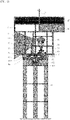
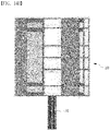
- FIG. 1 is a front view illustrating a structure in which turbine modules are arranged in two rows of a front row and a rear row in a hybrid power generation system according to an embodiment of the present invention.
- FIGS. 2A to 2C are magnified views illustrating a main part of the hybrid power generation system of FIG. 1 .
- FIG. 3 is a side view illustrating the hybrid power generation system of FIG. 1 .
- FIG. 4 is a top view illustrating the hybrid power generation system of FIG. 1 .
- FIG. 5 is a side view illustrating a structure in which turbine modules are arranged in single row in a hybrid power generation system according to an embodiment of the present invention.
- FIG. 6 is a top view illustrating the hybrid power generation system of FIG. 5 .
- FIG. 1 is a front view illustrating a structure in which turbine modules are arranged in two rows of a front row and a rear row in a hybrid power generation system according to an embodiment of the present invention.
- FIGS. 2A to 2C are magnif
- FIG. 7 is a drawing illustrating a shape viewed from a front of an inlet of a wind collecting duct in order to explain the configuration of a wind inducing means installed in the wind collecting duct according to an embodiment of the present invention.
- FIG. 8 is a drawing illustrating a wind inducing means viewed from a front of a wind collecting duct according to an embodiment of the present invention.
- FIG. 9 is a drawing illustrating a wind inducing means viewed from a rear of a wind collecting duct according to an embodiment of the present invention.
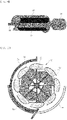
- FIG. 10 is a schematic top view illustrating configurations of a turbine module and elements for controlling wind volume with the turbine module according to an embodiment of the present invention.
- FIG. 11 is an exploded view illustrating some parts of a turbine module before assembly according to an embodiment of the present invention.
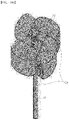
- FIG. 12 is a drawing illustrating a turbine module in which two types of blades having different shapes are coupled in a three-story stack according to an embodiment of the present invention.
- FIG. 13 is a drawing illustrating a turbine module before and after assembly in which blades having an identical shape are coupled in a three-story stack according to an embodiment of the present invention.
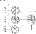
- FIGS. 14a to 14j are drawings illustrating turbine modules configured by different combinations of the shape and number of blades in according to embodiments of the present invention.
- a hybrid power generation system includes a power generation device and a system for operating and managing the same.
- the power generation device includes: a base frame 10 configured to be rotatable by a rotating means on a main rotation shaft 12; a wind collecting duct 20 provided on one end of the base frame 10 to introduce wind inside, increasing a speed of the introduced wind, and discharging the wind with increased speed; a turbine module 30 provided on a rear of the wind collecting duct 20 from which the wind is discharged and including a power generation rotation shaft 31 and a blade 32 installed on the power generation rotation shaft 31, wherein the blade 32 to which the wind discharged from the wind collecting duct 20 is provided rotates the power generation rotation shaft 31; a generator 40 connected to the power generation rotation shaft 31 and generating electric energy by a rotational force of the power generation rotation shaft 31, and a photovoltaic module concentration device 17.
- the shape of the inlet 20a may be a rectangle, a cylindrical shape, a round rectangle, or the like.
- the wind collecting duct 20 can be configured as separated parts and can be assembled on site for ease of transport and work. In this case, the wind collecting duct 20 may be configured to be separated horizontally or vertically.
- each plate of the wind collecting duct 20 may be configured to be separated vertically and/or horizontally, and thus, transport and workability on site can be further improved.
- a wind steering 11 is provided on the other end of the base frame 10 of the present invention.
- the base frame 10 can be rotated by the wind, and one end of the base frame 10 can automatically rotate toward a wind direction, a direction from which the wind blows.
- the inlet 20a of the wind collecting duct 20 automatically rotates toward the wind direction, and thus, the wind collecting efficiency is maximized.
- the rotating means in the present invention may be configured to include: a main rotation shaft 12 provided vertically at the bottom end of the base frame 10; a post 13 the top end of which the main rotation shaft 12 is rotatably installed on and that supports the bottom portion of the base frame 10; a support plate 14 fixed to the top end of the post 13 and coupled with the main rotation shaft 12 passing therethrough; a vertical motion gear 15 fixed to the support plate 14 and provided on a concentric axis with the main rotation shaft 12; the base frame 10 rotating, and a driving gear 16 preferably coupled to the base platform 19 and rotating in gear with the vertical motion gear 15.
- a support frame 13a may be fixed between the post 13 and the support plate 14 and may not rotate, enable the main rotation shaft 12 to rotate smoothly in a vertical state, and be configured to prevent the base frame 10 and the base platform 19 from collapsing by strong winds.
- the post 13 may be configured to have four columns or one cylindrical column perpendicular to the ground, such as a steel structure or a cylindrical structure, and may fixedly installed on the ground or the floor of the structure.
- the top portion of the support frame 13a may be fixedly coupled to the bottom portion of the support plate 14.
- the post 13 may be either a steel tower or a cylindrical tower.
- a collapse prevention frame 10a is fixed to the bottom part of the base platform 19 attached to the bottom part of the base frame 10 with the main rotation shaft 12 as a center.
- the bottom end of the collapse prevention frame 10a is bent inward and caught on the top end of the support plate 14, and thus, the base frame 10 and all the mechanical equipment connected to the base frame 10 and mounted on the base platform 19 are prevented from collapsing or fallen down.
- the rotating means may be configured to further include a wind direction rotation motor 16a providing a rotational force to a driving gear 16.
- the vertical motion gear 15 is fixed to the post 13 by the support plate 14, when the driving gear 16 is rotated by a rotational force provided by the wind direction rotation motor 16a, the driving gear 16 engaged with the vertical motion gear 15 rotates with respect to the vertical motion gear 15, and thus, the base frame 10 can rotate together.
- the present invention may further include: an angle measuring sensor for measuring a rotation angle of the main rotation shaft 12 by the wind steering 11, and a separate control unit for applying a driving signal to the wind direction rotation motor 16a when the rotation angle of the main rotation shaft 12 measured by the angle measurement sensor is equal to or greater than a reference angle.
- the wind direction rotation motor 16a is operated to rotate the base frame 10 in a direction in which the measured rotation angle is formed.
- the inlet 20a of the wind collecting duct 20 installed in the base frame 10 can stably rotate toward the wind direction, thereby increasing the wind collecting efficiency.
- the driving signal of the wind direction rotation motor 16a may be applied with a predetermined current for a predetermined time, thereby limiting excessive rotation of the base frame 10.
- the wind collecting duct 20 of the present invention may be formed to have a cross-sectional area that is gradually narrower as it goes from the inlet 20a to the outlet 20b.
- the wind collecting duct 20 sucks in outside air through the inlet 20a, which has a relatively large area, and according to Bernoulli's law, the wind collecting duct 20 discharges the sucked outside air at a high speed through the outlet 20b, which has a relatively narrow area. Accordingly, the speed and force of the wind passing through the wind collecting duct 20 is concentrated, thereby greatly increasing wind energy supplied to the turbine module 30.
- the cross section of the wind collecting duct 20 may have various shapes, such as a circular shape, a rectangular shape, as well as a rectangular shape illustrated in drawings.
- the present invention may further include a wind inducing means installed inside the wind collecting duct 20 to introduce wind into the wind collecting duct 20 and increase the speed of the introduced wind.
- the wind inducing means of the present invention may include: a wind inducing rotation shaft 21 installed along an edge of an inner surface of the inlet 20a or an edge of an inner surface of the outlet 20b of the wind collecting duct 20; a wind inducing rotation blade 22 rotatably installed on the wind inducing rotation shaft 21, and a wind inducing rotation motor 24 providing a rotational force to the wind inducing rotation shaft 21.
- the wind inducing rotation blade 22 forcibly sucks in outside air by the operation of the wind inducing rotation motor 24 and introduces the outside air into the wind collecting duct 20, whereby the volume and speed of the introduced wind are significantly increased.
- the wind with the increased volume and accelerated speed is strongly introduced into the blades 32 of the turbine module 30. Accordingly, a rotational torque and a rotational speed of the power generation rotation shaft 31 provided with the blades 32 are increased, and a rotational force and a centrifugal force of the blades 32 also increase. Thus, the power generation output is significantly enhanced.
- a main control unit 60 in FIG. 18 may control the wind inducing rotation motor 24 by applying a driving signal to the wind inducing rotation motor 24 and comparing an average operating rotation speed of each power generation rotation shaft 31 with a reference rotation speed. Specifically, when the average operating rotation speed is less than the reference rotation speed, the main control unit 60 allows wind inducing rotation motor 24 to be operated, and when the average operating rotation speed exceeds the reference rotation speed, the main control unit 60 controls the operation of the wind inducing rotation motor 24 to stop.
- the wind inducing rotation motor 24 may be operated with power generated by the photovoltaic module concentration device 17.
- the wind inducing rotation motor 24 stops operating, thereby extending the lifetime of the device and preventing power waste.
- the present invention may further include a windshield plate 23 having a shape surrounding the wind inducing rotation blade 22 between the wind inducing rotation shaft 21 and the inner surface of the inlet 20a of the wind collecting duct 20, or between the inner surface of the wind inducing rotation shaft 21 and the inner surface of the outlet 20b of the wind collecting duct 20.
- the upper portion of the wind inducing rotation blade 22 is surrounded by the windshield plate 23, and the windshield plate 23 blocks the wind introduced from the front of the inner side of the inlet 20a of the wind collecting duct 20 or from the front of the inner side of the outlet 20b, thereby preventing rotational resistance of the wind inducing rotating blade 22.
- the lower portion of the wind inducing rotation blade 22 is not surrounded by the windshield plate 23 and opened, and the introduced wind pushes the wind inducing rotation blade 22 in a direction in which the wind inducing rotation blade 22 rotates, thereby improving collecting efficiency of the wind inducing rotation blade 22.
- the wind inducing rotation blade 22 may be plural. Specifically, the plurality of the wind inducing rotation blades 22 may be installed on the whole or a portion of the edge of the inner side of the inlet 20a or the edge of the inner side of the outlet 20b. In this case, each wind inducing rotation motor 24 may be respectively installed for each wind inducing rotation blade 22, or installed for multiple wind inducing rotation blades 22 to provide a rotational force.
- the power generation rotation shaft 31 of the turbine module 30 is provided perpendicular to a direction in which the wind is discharged from the wind collecting duct 20, and a plurality of the blades 32 of the turbine module 30 may be provided radially with respect to the power generation rotation shaft 31.
- the turbine module 30 may be fixedly installed on a frame 70, which is horizontally provided at the middle of the base frame 10.
- the power generation rotation shaft 31 is provided vertically, and the blade 32 is horizontally coupled to the power generation rotation shaft 31 through a connecting rod 33 and rotates. Accordingly, the present invention has low noise, does not adversely affect the surrounding environment with noise, and is easy to install and maintain.
- the end of the blade 32 is opened to provide a blade wind collecting room 32a having a hollow inside.
- the open end of the blade wind collecting room 32a of the blade 32 may be disposed to face the outlet 20b of the wind collecting duct 20.
- the turbine module 30 may be disposed on both left and right side of the rear of the outlet 20b of the wind collecting duct 20.
- the turbine modules 30 may be arranged in two rows of the front row and the rear row as shown in FIG. 3 , or in single row at the front row as shown in FIG. 5 .
- the blade 32 may be disposed within a vertical length range of the outlet 20b of the wind collecting duct 20.
- the blade 32 may have a structure in which a circumferential length of the outer surface is longer than that of the inner surface with respect to the power generation rotation shaft 31.
- the outer surface of the blade 32 may be formed in a streamlined curved shape, and the inner surface of the blade 32 may be formed in a straight-line shape.
- the circumferential length of the outer surface of the blade 32 is formed longer than the circumferential length of the inner surface of the blade 32, when the blade 32 rotates, the speed and pressure difference occur between the outer surface and the inner surface, thereby further increasing a centrifugal force and a rotational force of the blade 32.
- the blades 32 are symmetrically coupled to the power generation rotation shaft 31 through the connecting rod 33, and the connecting rod 33 may be bolted to the blade 32. That is, a bolt shape formed at the end of the connecting rod 33 is fastened to a bolting hole 33a formed in the blade 32, so that the blade 32 is easily coupled to the power generation rotation shaft 31.
- the turbine module 30 may be configured to include the blades 32 having different or the same shape, and the number of blades 32 is appropriately selected according to the power generation capacity of the power generation device.
- the plurality of blades 32 can be installed symmetrically around the power generation rotation shaft 31.
- a vibration absorbing rotation cap 34 may be coupled to the top end of the power generation rotation shaft 31 as shown in FIGS. 2a to 2c .
- the vibration absorbing rotation cap 34 having a disk shape is coupled to the top end of the power generation rotation shaft 31, the vibration and noise generated by the powerful rotational force and centrifugal force of the blades 32 can be minimized. Accordingly, the vibration absorbing rotation cap 34 can also prevent breakdown of the turbine module 30 and prolong the lifetime of the power generation device.
- the present invention may further include a wind recollecting means at the rear of the wind collecting duct 20.
- the wind recollecting means recollects the wind, which passes through the wind collecting duct 20 and escapes from the rear of the turbine module 30, and resupplies the recollected wind to the front portion of the turbine module 30.
- the wind recollecting means recollects wind energy flowing backward, which was previously supplied to the blade wind collecting room 32a, and resupplies the recollected wind to the turbine module 30, the wind energy can be efficiently used.
- the wind recollecting means may be configured to include a wind recollecting member 50.
- One end of the wind recollecting member 50 is disposed at the rear of the rearmost turbine module 30, and the end of the one end of the wind recollecting member 50 is bent toward the wind collecting duct 20 to recollect the wind passing through the turbine module 30.
- the other end of the wind recollecting member 50 is disposed at the front of the turbine module 30, and is formed to have a curved shape from the one end to the other end, covering the outer surface of one side of the turbine module 30 to guide the wind recollected from one end toward the other end.
- the other end of the wind recollecting member 50 may be a wind recollecting discharge unit 52a for resupplying the recollected wind to the turbine module 30.
- the wind recollecting discharge unit 52a of the wind recollecting member 50 may be disposed at the front end of each turbine modules 30 disposed in the front and rear row, respectively.
- the wind recollecting discharge unit 52a of the wind recollecting member 50 may be disposed at the front end of the turbine modules 30 in the first row.
- the remaining wind which is left after the introduced wind is supplied to the turbine module 30, is recollected at the rear end of the wind recollecting member 50.
- the recollected wind is guided along the inner surface of the wind recollecting member 50 toward the front end of the wind recollecting member 50, and resupplied to the turbine module 30. Accordingly, the use of wind energy can be maximized.
- a windshield fence 51 may be provided to surround a part of the turbine module 30 on one side of the turbine module 30 facing toward the wind recollecting member 50.
- the windshield fence 51 may prevent the wind resupplied to the front end of the turbine module 30 through the wind recollecting member 50 from affecting the turbine module 30.
- the windshield fence 51 which is in a shape surrounding a part of the turbine module 30 on one side of the path through which the wind recollected from the wind recollecting member 50 is resupplied to the turbine module 30, the blade 32 rotated by the wind discharged from the outlet 20b of the wind collecting duct 20, does not receive the wind with the reverse rotation. Accordingly, the rotational force of the blade 32 is prevented from diminishing, and thus, the rotational force of the turbine module 30 can increase and breakdown can be prevented.
- a wind path forming member 52 for guiding the wind recollected from one end of the wind recollecting member 50 toward the other end may be further provided inside the wind recollecting member 50.
- a wind recollecting discharge unit 52a of the wind path forming member 52 is formed at the other end of the wind recollecting member 50.
- the path formed by the wind path forming member 52 is formed to have a gradually narrower cross-sectional area as the path goes from the entrance to the exit of the path, thereby increasing the wind speed of the wind resupplied from the wind recollecting means.
- the wind path forming member 52 when the wind path forming member 52 is disposed in two rows of the front and rear end of the turbine module 30, the wind path forming member 52 disposed at the rear end can form a path together with the windshield fence 51.
- the hybrid power generation system may further comprise an airflow volume control guide rail 53 having a shape surrounding the circumference of the turbine module 30 around the power generation rotation shaft 31 on the bottom of the frame 70.
- the present invention may be configured to include an airflow volume control rotating door 54 for controlling the airflow volume provided to the turbine module 30 from the wind collecting duct 20.
- the airflow volume control rotating door 54 is provided with wheels on the bottom end to be movable in the circumferential direction along the airflow volume control guide rail 53, and has a shape of a door surrounding a part of the front end of the turbine module 30.
- the present invention may be configured to include: an airflow volume control rotating door control motor (not shown) that provides a rotational force for rotating the airflow volume control rotating door 54 to the left and right, and a wind speed sensor 97, shown in FIG. 18 , that is installed at the inlet 20a and/or the outlet 20b of the wind collecting duct 20 to measure the wind speed value of wind passing through the wind collecting duct 20.
- the main control unit 60 shown in FIG. 18 , can apply a driving signal to the airflow volume control rotating door control motor, and may adjust the movement of the airflow volume control rotating door 54 according to an input value input from the wind speed sensor 97.
- the wind speed sensor 97 may be installed on the front portion of the top end of the wind collecting duct 20, the inlet 20a, or the outlet 20b.
- the power generation device may further include various sensors such as a rain gauge or a barometer in addition to the wind speed sensor 97.
- the main control unit 60 controls the power generation device by comparing the input values input by the sensors with reference values.
- the airflow volume control rotating door 54 is automatically rotated and moved by the control of the main control unit 60 along the airflow volume control guide rail 53 according to the input value corresponding to the wind discharged by the wind collecting duct 20, the wind volume discharged from the outlet 20b and supplied to the blade 32 can be controlled. Accordingly, by automatically adjusting the airflow volume control rotating door 54, it is possible to prevent excessive strong wind that adversely affects the power generation device from introducing into the wind collecting duct 20 and to prevent malfunction of the turbine module 30.
- the wind volume control rotating door 54 installed on the left rotates counterclockwise to the end of the left airflow volume control guide rail 53 and moves to the right.
- the airflow volume control rotating door 54 installed on the right rotates clockwise to the end of the right airflow volume control guide rail 53 and moves to the left.
- the present invention may further include a wind recollecting prevention door provided in the wind recollecting member, and a wind recollecting prevention door guide rail.
- a wind recollecting prevention door provided in the wind recollecting member
- a wind recollecting prevention door guide rail In this case, when the wind speed of the typhoon is 20 m/s or more, the wind recollecting prevention door moves along wind recollecting prevention door guide rail and closes, and the recollected wind does not enter into the inside of the wind recollecting member and directly goes out to the outside.
- the turbine module 30 stops rotating.
- a multiplying gearbox 35 is connected between the power generation rotation shaft 31 and the generator 40 to increase speed of rotation provided to the generator 40 from the power generation rotation shaft 31.
- the multiplying gearbox 35 with a gear ratio formed by several large and small gears increases the number of rotations of the power generation rotation shaft 31 to increase electric energy.
- the present invention may be configured to include: a braking device 36 installed to brake the power generation rotation shaft 31, and a separate control unit for inputting a braking signal to the braking device 36.
- the braking signal is input to the braking device 36 when the rotational speed of the power generation rotation shaft 31 exceeds a braking reference rotational speed.
- the braking device 36 may stop the power generation rotation shaft 31 to prevent damage to the power generation device or an accident in case that the rotational force by the power generation rotation shaft 31 is too strong.
- the multiplying gearbox 35 is connected to the power generation rotation shaft 31.
- the power generation rotation shaft 31 is integrally coupled to a shaft 38 of a rotating member 37 coupled to the top portion of the generator 40. That is, when the generator 40 is configured as a gearless type, the multiplying gearbox 35 is not applied.
- the photovoltaic module concentration device 17 is installed on the top end of the post 13.
- the photovoltaic module concentration device 17 may provide power to the wind inducing rotation motor 24 installed at the inlet 20a and the outlet 20b of the wind collecting duct 20.
- the photovoltaic module concentration device 17 may be a solar cell concentration panel.
- a lightning arrester 18 may be installed at the uppermost end of the power generation device.
- the lightning arrester 18 provided higher than the photovoltaic module concentration device 17 can protect the power generation system by guiding the lightning to the ground. That is, the present invention can solve a problem of the conventional horizontal shaft generator in which a blade induces the lightning.
- each of the motors of the present invention may be operated by electricity generated by the photovoltaic module concentration device 17 and the generator 40.
- the present invention further includes a wind recollecting pipe 55 extended from the wind recollecting member 50 and coupled to both top end portions or middle end portions of the wind collecting duct 20.
- a wind recollecting pipe 55 communicates with the wind recollecting member 50 and the top end portion or middle end portion of the wind collecting duct 20.
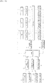
- FIG. 18 is a block diagram schematically illustrating internal configurations of a hybrid power generation device according to an embodiment of the present invention.
- FIG. 19 is a block diagram schematically illustrating internal configurations of a photovoltaic module concentration device, a wind inducing rotating motor, a generator, and a photovoltaic control unit connected thereto according to an embodiment of the present invention.
- FIG. 20 is a diagram illustrating a connection between a hybrid power generation system and a drone device according to an embodiment of the present invention.
- the hybrid power generation system may further includes: a battery 80, a BMS 82, a battery control unit 84, a CCTV camera 85, an infrared camera 86, and an image processing unit 87, the wind speed sensor 97, the generator 40, the photovoltaic module concentration device 17, and the main control unit 60.
- a drone device 100 may be further included in the hybrid power generation system.
- the CCTV camera 85 and the infrared camera 86 selectively operates during the day and at night to capture images of the surroundings of the generator 40 and generates image information for fire monitoring and moving or fixed objects.
- the image processing unit 87 may process and store the image information generated from the CCTV camera 85 and the infrared camera 86, and transmit the monitored image information to an external management server 89 or a mobile terminal 89a through a wireless communication unit 88 according to a control signal of the main control unit 60.
- the main control unit 60 When the main control unit 60 receives one or more signal of a fire signal, temperature information above a reference temperature value, heat information, smoke information, and a flame signal, from a detection sensor unit (not shown) installed on one side of the power generation device, a camera driving signal may be transmitted to the CCTV camera 85 and the infrared camera 86, and generated image information may be transmitted to the external management server 89 or the mobile terminal 89a through the wireless communication unit 88.
- the detection sensor unit includes a fire detection sensor, a flame detection sensor, a heat detection sensor, a smoke detection sensor, and a temperature sensor.
- the wind speed sensor 97 is installed on the wind collecting duct 20 to measure a wind speed value, which is a strength of wind, and transmits the measured wind speed value to the main control unit 60.
- the generator 40 is electrically connected to each of a plurality of batteries ESS 80, which charges and discharges electric energy according to the rotation of the turbine module 30 by wind power.
- the generator 40 is electrically connected to each of the plurality of photovoltaic module concentration devices 17 so that the plurality of photovoltaic module concentration devices 17 supply electric energy to each motor.
- the battery 80 is a system for storing electric energy generated by the generator 40, and charging and discharging electric energy. Each battery 80 is electrically connected to each BMS 82.
- the generator 40 is electrically connected to each of the plurality of photovoltaic module concentration devices 17 so that the plurality of photovoltaic module concentration devices 17 supply electric energy to each motor.
- the BMS 82 is a battery management system that detects voltage, current, temperature, heat, smoke, and other factors of the battery 80 to protect the battery 80.
- the BMS 82 controls the charge and discharge amount of the battery 80 to an appropriate level, performs cell balancing of the battery 80, and identifies and controls the remaining capacity of the battery 80.
- the BMS 82 protects the battery 80 and the hybrid power generation system through emergency operation of a fire extinguishing device (not shown) when a fire is detected.
- energy generated during discharging the battery 80 is recharged in an energy storage device such as a secondary battery, and thus, the total energy can be managed by using the recharged energy in the power generation system.
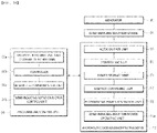
- the photovoltaic module concentration device 17 includes: a photovoltaic power generation unit 91 equipped with a solar cell generating electric energy by receiving sunlight; a voltage comparing unit 92 connected to an output terminal of the photovoltaic power generation unit 91 to detect an output voltage and compare the output voltage with a reference voltage and including a constant voltage circuit, a voltage boost circuit, and a constant current circuit; a power storage unit 93 storing the electric energy; a control module 94 controlling to output the electric energy to a AC/DC output unit 95, and a wind inducing rotation motor operation unit 24a for operating the wind inducing rotation motor 24 in FIG. 7 .
- the photovoltaic power generation unit 91 may be a solar cell array.
- the solar cell array is formed by combining a plurality of solar cell modules.
- a solar cell module is a device that converts solar energy into electric energy and generates a predetermined voltage and current by connecting a plurality of solar cells in series or in parallel. Accordingly, the solar cell array absorbs solar energy and converts the solar energy into electric energy.
- Each photovoltaic module concentration device 17 is electrically connected a photovoltaic control unit 96.
- the photovoltaic control unit 96 may be configured to include: a voltage detecting unit and a current detecting unit 96a connected to a panel output line of the photovoltaic power generation unit 91 to respectively detect a voltage and a current of electric energy output from the photovoltaic panel; a controller 96b calculating the levels of the current and voltage detected by the voltage detecting unit and current detecting unit 96a and controlling a RF wireless communication unit 96c to transmit data including the levels of the detected current and voltage; the RF wireless communication unit 96c wirelessly transmitting the data generated by the controller 96b, and a wind inducing rotation motor control unit 24b for controlling the wind inducing rotation motor operation unit 24a.
- the main control unit 60 compares the calculated levels of current and voltage with those of preset reference voltage and current. When the calculated levels of current and voltage exceeds the preset reference voltage and current, the main control unit 60 may generate and transmit a warning signal to the external management server 89 or the mobile terminal 89a through the wireless communication unit 88.
- Each battery 80 is electrically connected to the battery control unit 84 that monitors the voltage of each battery cell in real time.
- the battery control unit 84 measures the voltage of each battery cell, sets one of the measured voltages as a balancing reference voltage, and performs balancing through charging and discharging based on the balancing reference voltage.
- the battery control unit 84 connects a current sensing resistor to the battery cell in series to measure the potential difference between both ends of the cell, and uses the measured potential difference to identify the current direction in the battery cell to determine the state of charge.
- the battery control unit 84 measures voltages of the battery cells and calculates a voltage deviation between the plurality of the battery cells. When the calculated voltage deviation of the battery cells is greater than or equal to a predetermined reference value, the battery control unit 84 controls the system by determining that cell balancing is necessary and communicating with the photovoltaic module concentration device 17 to allow the battery cells to selectively receive a voltage from the photovoltaic module concentration device 17 to perform cell balancing.
- the battery control unit 84 periodically receives information of the remaining capacity of the battery cell and transmits the information of the remaining capacity to the main control unit 60.
- the main control unit 60 analyzes the remaining capacity of the cells received from each battery 80. When the main control unit 60 determines that the remaining capacity of the cell is less than or equal to a preset reference capacity value, the main control unit 60 controls the system by generating and transmitting an energy supplying signal to the photovoltaic module concentration device 17, while the battery having the reference capacity value or less performs a charging process, and allowing the electric energy obtained from the photovoltaic module concentration device 17 to be provided to the wind inducing rotation motor 24 or the generator 40.
- the main control unit 60 controls the system by generating and transmitting an energy supplying signal, and allowing the electric energy obtained from the photovoltaic module concentration device 17 to be provided to the wind inducing rotation motor 24 or the generator 40.
- the hybrid power generation system of the present invention can generate electric energy by driving the wind inducing rotation motor 24, forming wind, and operating the turbine module 30 even when natural wind is not blowing enough.
- the main control unit 60 When the main control unit 60 receives a drone driving signal from the external management server 89 or the mobile terminal 89a, the main control unit 60 transmits the drone driving signal to a drone control unit 106 of a drone main body 107 through the wireless communication unit 88.
- the drone device 100 of the embodiment of the present invention has a drone main body 107 having a certain shape, and transmits and receives data and control signals to and from the main control unit 60 of the hybrid power generation system.
- the drone main body 107 is formed in a certain shape, such as a square box, to protect the devices inside from external pressure or shock.
- the drone main body 107 includes an operation management system that monitors fire and the hybrid power generation system by capturing images of a specific object, for example, surrounding environment of the generator 40 in real time, by one or more cameras 101 mounted on the top, the center, or the bottom of the center portion, or the left and right of the side portion of the drone main body 107.
- the cameras 101 may be configured using technologies based on Internet of Things (loT), the Artificial Intelligence (Al), and the like. Accordingly, the potential danger in the hybrid power generation system can be detected in advance, thereby reducing the risk of breakdown of the system.
- a camera control unit 102 controls a camera unit 101 to rotate up, down, left, right, and 360 degrees, and controls a camera zoom actuator (not shown) to operate and zoom in or out.
- a GPS module 103 is positioned on one side of the front end of the drone main body 107, and generates a current position coordinate of the drone main body 107, by performing data processing of coordinate information received from the drone main body 107 before and after takeoff and after landing of the drone main body 107 in real time.
- a sensor module 104 is positioned on top end of the drone main body 107 of the drone, and detects detailed information necessary for flying the drone.
- a rotation motor module 105 is positioned inside the drone main body 107 to rotate rotating blades at the same rotation speed and the same torque at high speed.
- the drone control unit 106 controls overall operations of the drone main body 107. Specifically, the drone control unit 106 receives a flight control command signal of the drone device 100 from a loT type drone control application module; controls the drone main body 107 to land, take off, fly, and performing hovering flight by moving a rotation axis of the rotation motor module 105 and adjusting the position and the speed, and transmits captured image data and flight response signal to the loT type drone control application module.
- the main control unit 60 When the main control unit 60 receives at least one of a fire signal, temperature information above a preset temperature value, heat information, smoke information, and a flame signal from the detection sensor unit (not shown) installed on one side of the power generation system, the main control unit 60 generates and transmits a flight control command signal to the drone control unit 106.
- the drone control unit 106 may transmit a driving signal to the GPS module 103, the sensor module 104, the rotation motor module 105, and the camera control unit 102 to acquire various image information of a place where danger is detected and also transmit the acquired image information to the external management server 89 or the mobile terminal 89a through the wireless communication unit 88.
Applications Claiming Priority (2)
| Application Number | Priority Date | Filing Date | Title |
|---|---|---|---|
| KR1020190093949A KR102068280B1 (ko) | 2019-08-01 | 2019-08-01 | 하이브리드 발전시스템 |
| PCT/KR2020/007799 WO2021020728A1 (ko) | 2019-08-01 | 2020-06-17 | 하이브리드 발전시스템 |
Publications (2)
| Publication Number | Publication Date |
|---|---|
| EP4009516A1 true EP4009516A1 (de) | 2022-06-08 |
| EP4009516A4 EP4009516A4 (de) | 2022-09-28 |
Family
ID=69369614
Family Applications (1)
| Application Number | Title | Priority Date | Filing Date |
|---|---|---|---|
| EP20848498.0A Pending EP4009516A4 (de) | 2019-08-01 | 2020-06-17 | Hybridstromerzeugungssystem |
Country Status (7)
| Country | Link |
|---|---|
| US (1) | US20220263453A1 (de) |
| EP (1) | EP4009516A4 (de) |
| JP (1) | JP2022543405A (de) |
| KR (1) | KR102068280B1 (de) |
| CN (1) | CN114174674A (de) |
| AU (1) | AU2020321531B2 (de) |
| WO (1) | WO2021020728A1 (de) |
Families Citing this family (1)
| Publication number | Priority date | Publication date | Assignee | Title |
|---|---|---|---|---|
| KR102068280B1 (ko) * | 2019-08-01 | 2020-01-21 | 이윤원 | 하이브리드 발전시스템 |
Family Cites Families (21)
| Publication number | Priority date | Publication date | Assignee | Title |
|---|---|---|---|---|
| ITRM20020027A1 (it) * | 2002-01-22 | 2003-07-22 | Telecom Italia Mobile Spa | Stazione radio base per telefonia mobile cellulare con centrale di energia elettrica da sorgente fotovoltaica-eolica a funzionamento continu |
| JP2005051955A (ja) * | 2003-07-31 | 2005-02-24 | Minoru Kuroiwa | 太陽光発電と風力発電のハイブリッド発電システム |
| RU2251022C1 (ru) * | 2003-11-13 | 2005-04-27 | Зазимко Вадим Николаевич | Ветроэнергетическая установка |
| KR20040016913A (ko) | 2004-01-26 | 2004-02-25 | 이인우 | 태양광/풍력 복합 발전 시스템에 사용되는 풍력발전장치 |
| US7245039B2 (en) * | 2004-12-10 | 2007-07-17 | Duhamel Robert A | Apparatus and method for generating hydrogen gas through the use of wind power |
| KR20100035289A (ko) * | 2008-09-26 | 2010-04-05 | 김용주 | 풍력발전장치의 발전기동풍속을 보정 가능하게 하는 복합발전시스템 |
| ITVA20090039A1 (it) * | 2009-06-29 | 2010-12-30 | Gabriele Biucchi | Dispositivo per la produzione di energia elettrica e termica da energia eolica e solare tramite turbina ad asse verticale |
| US9422922B2 (en) * | 2009-08-28 | 2016-08-23 | Robert Sant'Anselmo | Systems, methods, and devices including modular, fixed and transportable structures incorporating solar and wind generation technologies for production of electricity |
| CN201621005U (zh) * | 2009-11-16 | 2010-11-03 | 温州大学 | 风光互补发电设备的自动监控与保护装置 |
| KR101132921B1 (ko) * | 2010-03-18 | 2012-04-03 | 이윤원 | 코일 권선식 자동 전압 조절기 |
| KR101409774B1 (ko) * | 2014-02-14 | 2014-06-25 | 주식회사 텐코리아 | 태양광 발전 시설 모니터링 시스템에 적용되는 개별 솔라셀 패널 감시 장치 |
| KR101577901B1 (ko) * | 2014-06-30 | 2015-12-17 | 이윤원 | 하이브리드 발전장치 |
| KR101509536B1 (ko) * | 2014-12-29 | 2015-04-08 | 주식회사 대경산전 | 태양광 발전 모니터링시스템 |
| KR20170058661A (ko) * | 2015-11-19 | 2017-05-29 | 주식회사 네오텍 | 풍력과 태양광 기반의 하이브리드 충전 컨트롤러 및 충전 제어방법 |
| PL228025B1 (pl) * | 2015-11-24 | 2018-02-28 | Ireneusz Piskorz | Agregat do wykorzystania energii słonecznej i wiatru |
| KR102025286B1 (ko) * | 2016-07-12 | 2019-09-26 | 주식회사 엘지화학 | 배터리 셀 밸런싱의 방법 및 시스템 |
| KR101765235B1 (ko) * | 2016-11-28 | 2017-08-04 | 한국건설기술연구원 | 사물인터넷 기반 센서와 무인비행체를 이용한 시설물 유지관리 시스템 및 그 방법 |
| KR20190019830A (ko) * | 2017-08-18 | 2019-02-27 | 주식회사 에니텍시스 | 자가발전이 가능한 IoT 기반의 시설물 관리 시스템 |
| CN108547737A (zh) * | 2018-05-31 | 2018-09-18 | 黑龙江冰峰科技有限公司 | 一种新能源汽车组合式充电装置 |
| KR101916374B1 (ko) * | 2018-06-07 | 2018-11-07 | (주)수산인더스트리 | 드론을 이용한 화재 경보 시스템 및 방법 |
| KR102068280B1 (ko) * | 2019-08-01 | 2020-01-21 | 이윤원 | 하이브리드 발전시스템 |
-
2019
- 2019-08-01 KR KR1020190093949A patent/KR102068280B1/ko active IP Right Grant
-
2020
- 2020-06-17 AU AU2020321531A patent/AU2020321531B2/en active Active
- 2020-06-17 WO PCT/KR2020/007799 patent/WO2021020728A1/ko unknown
- 2020-06-17 CN CN202080054782.0A patent/CN114174674A/zh active Pending
- 2020-06-17 EP EP20848498.0A patent/EP4009516A4/de active Pending
- 2020-06-17 JP JP2022506738A patent/JP2022543405A/ja active Pending
- 2020-06-17 US US17/628,967 patent/US20220263453A1/en active Pending
Also Published As
| Publication number | Publication date |
|---|---|
| AU2020321531B2 (en) | 2023-12-14 |
| CN114174674A (zh) | 2022-03-11 |
| US20220263453A1 (en) | 2022-08-18 |
| AU2020321531A1 (en) | 2022-03-24 |
| WO2021020728A1 (ko) | 2021-02-04 |
| EP4009516A4 (de) | 2022-09-28 |
| JP2022543405A (ja) | 2022-10-12 |
| KR102068280B1 (ko) | 2020-01-21 |
Similar Documents
| Publication | Publication Date | Title |
|---|---|---|
| US9291150B2 (en) | Systems and methods to generate electricity using a flow of air | |
| KR102245359B1 (ko) | 풍력발전기의 블레이드를 따라 이동 가능한 구조를 포함하는 풍력발전기 점검용 드론 | |
| WO2014201018A1 (en) | Wind energy devices, systems, and methods | |
| KR20130069334A (ko) | 풍력 에너지로부터 전력을 발생시키기 위한 풍력 발전 장치 | |
| EP4009516A1 (de) | Hybridstromerzeugungssystem | |
| EP2726736B1 (de) | Fernmesssystem für windturbinen | |
| EP1672214B1 (de) | Windturbine mit senkrechter Drehachse mit einem Steuersystem für Drachen | |
| CN108316167B (zh) | 一种旋转式无人机停机坪 | |
| US9581135B2 (en) | Cable-suspended wind energy generator | |
| CN101776045B (zh) | 矩阵式风力发电装置 | |
| JPH06257554A (ja) | 風力発電装置 | |
| CN111487640A (zh) | 一种海上扫描式激光雷达测风装置及方法 | |
| CN109956048A (zh) | 一种应用于海上风力发电设备的无人机停靠系统 | |
| KR101577901B1 (ko) | 하이브리드 발전장치 | |
| CN111026158A (zh) | 一种基于雷达的无人机监测平台 | |
| EP2706227A2 (de) | Strömungskraftwerk zur Nutzung eines Aufwindes | |
| CN111137439B (zh) | 一种飞行机器人避障装置及飞行机器人的避障方法 | |
| CN109185061B (zh) | 一种风阵发电系统 | |
| WO2010123461A1 (en) | A wind turbine comprising a rotor | |
| WO2013189503A2 (en) | High altitude maglev vertical-axis wind turbine system (ham-vawt) | |
| US20150354538A1 (en) | Rotating magnetic wind generator | |
| CN112783212A (zh) | 一种光伏发电巡检用无人机 | |
| KR101353951B1 (ko) | 풍력 발전기 | |
| KR200285677Y1 (ko) | 풍력 발전장치 | |
| CN220363485U (zh) | 一种多仓无人机机场 |
Legal Events
| Date | Code | Title | Description |
|---|---|---|---|
| STAA | Information on the status of an ep patent application or granted ep patent |
Free format text: STATUS: THE INTERNATIONAL PUBLICATION HAS BEEN MADE |
|
| PUAI | Public reference made under article 153(3) epc to a published international application that has entered the european phase |
Free format text: ORIGINAL CODE: 0009012 |
|
| STAA | Information on the status of an ep patent application or granted ep patent |
Free format text: STATUS: REQUEST FOR EXAMINATION WAS MADE |
|
| 17P | Request for examination filed |
Effective date: 20220301 |
|
| AK | Designated contracting states |
Kind code of ref document: A1 Designated state(s): AL AT BE BG CH CY CZ DE DK EE ES FI FR GB GR HR HU IE IS IT LI LT LU LV MC MK MT NL NO PL PT RO RS SE SI SK SM TR |
|
| A4 | Supplementary search report drawn up and despatched |
Effective date: 20220830 |
|
| RIC1 | Information provided on ipc code assigned before grant |
Ipc: H02J 7/35 20060101ALI20220824BHEP Ipc: H02J 7/00 20060101ALI20220824BHEP Ipc: F03D 3/00 20060101ALI20220824BHEP Ipc: F03D 9/00 20160101ALI20220824BHEP Ipc: F03D 9/11 20160101ALI20220824BHEP Ipc: G08C 17/02 20060101ALI20220824BHEP Ipc: G08B 17/06 20060101ALI20220824BHEP Ipc: H02S 50/00 20140101ALI20220824BHEP Ipc: H02S 10/20 20140101ALI20220824BHEP Ipc: H02S 10/12 20140101AFI20220824BHEP |
|
| DAV | Request for validation of the european patent (deleted) | ||
| DAX | Request for extension of the european patent (deleted) | ||
| GRAP | Despatch of communication of intention to grant a patent |
Free format text: ORIGINAL CODE: EPIDOSNIGR1 |
|
| STAA | Information on the status of an ep patent application or granted ep patent |
Free format text: STATUS: GRANT OF PATENT IS INTENDED |