EP4008972B1 - Verfahren und system zum betrieb einer luftbehandlungseinheit mit effektivem statischem druck - Google Patents
Verfahren und system zum betrieb einer luftbehandlungseinheit mit effektivem statischem druck Download PDFInfo
- Publication number
- EP4008972B1 EP4008972B1 EP21212494.5A EP21212494A EP4008972B1 EP 4008972 B1 EP4008972 B1 EP 4008972B1 EP 21212494 A EP21212494 A EP 21212494A EP 4008972 B1 EP4008972 B1 EP 4008972B1
- Authority
- EP
- European Patent Office
- Prior art keywords
- ahu
- static pressure
- vav
- setpoint
- airflow
- Prior art date
- Legal status (The legal status is an assumption and is not a legal conclusion. Google has not performed a legal analysis and makes no representation as to the accuracy of the status listed.)
- Active
Links
Images


Classifications
-
- F—MECHANICAL ENGINEERING; LIGHTING; HEATING; WEAPONS; BLASTING
- F24—HEATING; RANGES; VENTILATING
- F24F—AIR-CONDITIONING; AIR-HUMIDIFICATION; VENTILATION; USE OF AIR CURRENTS FOR SCREENING
- F24F11/00—Control or safety arrangements
- F24F11/70—Control systems characterised by their outputs; Constructional details thereof
- F24F11/72—Control systems characterised by their outputs; Constructional details thereof for controlling the supply of treated air, e.g. its pressure
-
- F—MECHANICAL ENGINEERING; LIGHTING; HEATING; WEAPONS; BLASTING
- F24—HEATING; RANGES; VENTILATING
- F24F—AIR-CONDITIONING; AIR-HUMIDIFICATION; VENTILATION; USE OF AIR CURRENTS FOR SCREENING
- F24F11/00—Control or safety arrangements
- F24F11/70—Control systems characterised by their outputs; Constructional details thereof
- F24F11/72—Control systems characterised by their outputs; Constructional details thereof for controlling the supply of treated air, e.g. its pressure
- F24F11/74—Control systems characterised by their outputs; Constructional details thereof for controlling the supply of treated air, e.g. its pressure for controlling air flow rate or air velocity
- F24F11/77—Control systems characterised by their outputs; Constructional details thereof for controlling the supply of treated air, e.g. its pressure for controlling air flow rate or air velocity by controlling the speed of ventilators
-
- F—MECHANICAL ENGINEERING; LIGHTING; HEATING; WEAPONS; BLASTING
- F24—HEATING; RANGES; VENTILATING
- F24F—AIR-CONDITIONING; AIR-HUMIDIFICATION; VENTILATION; USE OF AIR CURRENTS FOR SCREENING
- F24F11/00—Control or safety arrangements
- F24F11/30—Control or safety arrangements for purposes related to the operation of the system, e.g. for safety or monitoring
- F24F11/46—Improving electric energy efficiency or saving
-
- F—MECHANICAL ENGINEERING; LIGHTING; HEATING; WEAPONS; BLASTING
- F24—HEATING; RANGES; VENTILATING
- F24F—AIR-CONDITIONING; AIR-HUMIDIFICATION; VENTILATION; USE OF AIR CURRENTS FOR SCREENING
- F24F11/00—Control or safety arrangements
- F24F11/62—Control or safety arrangements characterised by the type of control or by internal processing, e.g. using fuzzy logic, adaptive control or estimation of values
- F24F11/63—Electronic processing
- F24F11/64—Electronic processing using pre-stored data
-
- F—MECHANICAL ENGINEERING; LIGHTING; HEATING; WEAPONS; BLASTING
- F24—HEATING; RANGES; VENTILATING
- F24F—AIR-CONDITIONING; AIR-HUMIDIFICATION; VENTILATION; USE OF AIR CURRENTS FOR SCREENING
- F24F11/00—Control or safety arrangements
- F24F11/70—Control systems characterised by their outputs; Constructional details thereof
- F24F11/72—Control systems characterised by their outputs; Constructional details thereof for controlling the supply of treated air, e.g. its pressure
- F24F11/74—Control systems characterised by their outputs; Constructional details thereof for controlling the supply of treated air, e.g. its pressure for controlling air flow rate or air velocity
-
- F—MECHANICAL ENGINEERING; LIGHTING; HEATING; WEAPONS; BLASTING
- F24—HEATING; RANGES; VENTILATING
- F24F—AIR-CONDITIONING; AIR-HUMIDIFICATION; VENTILATION; USE OF AIR CURRENTS FOR SCREENING
- F24F3/00—Air-conditioning systems in which conditioned primary air is supplied from one or more central stations to distributing units in the rooms or spaces where it may receive secondary treatment; Apparatus specially designed for such systems
- F24F3/001—Air-conditioning systems in which conditioned primary air is supplied from one or more central stations to distributing units in the rooms or spaces where it may receive secondary treatment; Apparatus specially designed for such systems in which the air treatment in the central station takes place by means of a heat-pump or by means of a reversible cycle
-
- F—MECHANICAL ENGINEERING; LIGHTING; HEATING; WEAPONS; BLASTING
- F24—HEATING; RANGES; VENTILATING
- F24F—AIR-CONDITIONING; AIR-HUMIDIFICATION; VENTILATION; USE OF AIR CURRENTS FOR SCREENING
- F24F2110/00—Control inputs relating to air properties
- F24F2110/30—Velocity
-
- F—MECHANICAL ENGINEERING; LIGHTING; HEATING; WEAPONS; BLASTING
- F24—HEATING; RANGES; VENTILATING
- F24F—AIR-CONDITIONING; AIR-HUMIDIFICATION; VENTILATION; USE OF AIR CURRENTS FOR SCREENING
- F24F2110/00—Control inputs relating to air properties
- F24F2110/40—Pressure, e.g. wind pressure
-
- F—MECHANICAL ENGINEERING; LIGHTING; HEATING; WEAPONS; BLASTING
- F24—HEATING; RANGES; VENTILATING
- F24F—AIR-CONDITIONING; AIR-HUMIDIFICATION; VENTILATION; USE OF AIR CURRENTS FOR SCREENING
- F24F2140/00—Control inputs relating to system states
- F24F2140/40—Damper positions, e.g. open or closed
-
- F—MECHANICAL ENGINEERING; LIGHTING; HEATING; WEAPONS; BLASTING
- F24—HEATING; RANGES; VENTILATING
- F24F—AIR-CONDITIONING; AIR-HUMIDIFICATION; VENTILATION; USE OF AIR CURRENTS FOR SCREENING
- F24F2140/00—Control inputs relating to system states
- F24F2140/50—Load
Definitions
- HVAC heating, ventilation, and air conditioning
- HVAC Heating, ventilation, and air conditioning
- AHU air handling unit
- VAV variable air volume
- Each of the VAV units may use diffusers to serve different zones/areas of the building. Particularly, each zone of the building may have a few diffusers connected with a VAV unit for maintaining a desired temperature in that zone. This helps in maintaining different cooling or heating temperatures at the same time in various zones of the building.
- static pressure setpoint in the AHU needs to be maintained by controlling fan speed of the AHU. Further, for controlling the fan speed of the AHU, static pressure setpoint of the AHU is kept at a constant value which operates in a system resistance curve i.e. static pressure/ cubic feet per minute (cfm) when the speed of the fan varies.
- the static pressure of the AHU can be reset using a trim & respond method which operates by monitoring a maximum value of a damper position of all VAV units & for higher position value, the static pressure setpoint is increased & vice versa clamping to a higher or a lower limit which are manually calculated/approximated.
- the trim & respond method is inefficient due to randomly changing static pressure which may not follow a system impedance curve.
- dampers of the VAV units are in an intermediate position which adds impedance in an airflow casing system curve to deflect inwards, thereby resulting in more losses.
- a balancer In order to determine the AHU static pressure setpoint, a balancer requires a lot of time and does all the work manually to define the static pressure setpoint.
- any HVAC system is designed based on the requirements at the location where the system is installed. But the actual installation requires several changes and adjustments in piping/ductwork of the HVAC. Accordingly, the designed HVAC systems seldom work ideally as planned.
- JP 2018173206 A discloses a device for controlling a plurality of variable air volume (VAV) units.
- the VAV unit control device calculates the required air volume to be provided to the room to achieve the set temperature, and requests the calculated air volume from the air conditioner. Provided the control device determines that this calculated air volume can be achieved, the required air volume of each room/VAV unit is totalled and the static pressure of a blower fan of the air conditioner is calculated using the air volume characteristic.
- a method for operating an air handling unit (AHU) at an effective static pressure setpoint comprising: receiving airflow setpoint values from each of a plurality of variable air volume (VAV) units to determine a combined airflow set point for the plurality of VAV units of an air handling unit (AHU); determining an effective static pressure setpoint for the AHU based on a relation between the combined airflow setpoint value and a static pressure represented by a system effect curve; operating the AHU at the effective static pressure setpoint; monitoring a damper position of each VAV unit for determining a starving VAV unit from the plurality of VAV units and computing the effective static pressure setpoint of the AHU; determining an offset for the starving VAV unit; and adjusting the offset to the effective static pressure setpoint of the AHU for the starving VAV unit.
- VAV variable air volume
- the adjustment of the offset to the effective static pressure setpoint of the AHU is achieved by either increasing or decreasing the effective static pressure setpoint of the AHU.
- the method further comprises the steps of automatically monitoring and learning an effect of the adjustment of the offset to the effective static pressure setpoint of the AHU for efficient operation of each of the plurality of VAV units.
- the method further comprises the steps of determining a second starving VAV unit and a second offset based on the effect of the adjustment of the offset to the effective static pressure setpoint of the AHU.
- the airflow setpoint values of each of the plurality of VAV units is determined based on load requirement, a value of maximum allowed airflow setpoint & a value of minimum allowed airflow setpoint.
- the effective static pressure setpoint is obtained by varying the speed of a fan to meet the demand of the effective static pressure setpoint.
- the fan operates in accordance with the system effect curve to follow a least impedance airflow path.
- the AHU is connected with each of the VAV units through one or more ducts.
- the method further comprises steps of monitoring an existing static pressure control strategy instantaneous value at a defined interval time along with a recorded data to compare it with an impedance curve.
- the method further comprises steps of equating and showing energy losses to a user due to not following the impedance curve.
- a system for operating an air handling unit (AHU) at an effective static pressure setpoint comprising a plurality of variable air volume (VAV) units configured to determine airflow setpoint values and communicate the airflow setpoint values; and an air handling unit (AHU) comprising a controller, the controller configured to: receive the airflow setpoint values from each of the VAV units; determine a combined airflow set point for the plurality of VAV units of the AHU; determine an effective static pressure setpoint based on a relation between the combined airflow setpoint value and a static pressure represented by a system effect curve; operate the AHU at the effective static pressure setpoint; monitor a damper position of each VAV unit for determining a starving VAV unit from the plurality of VAV units and compute the effective static pressure setpoint of the AHU; determine an offset for the starving VAV unit; and adjust the offset to the effective static pressure setpoint of the AHU for the starving VAV unit.
- VAV variable air volume
- the adjustment of the offset to the effective static pressure setpoint of the AHU is achieved by either increasing or decreasing the effective static pressure setpoint of the AHU.
- the controller is further configured to automatically monitor and learn an effect of the adjustment of the offset to the effective static pressure setpoint of the AHU for efficient operation of each of the plurality of VAV units.
- the controller is further configured to determine a second starving VAV unit and a second offset based on the effect of the adjustment of the offset to the effective static pressure setpoint of the AHU.
- the effective static pressure setpoint is obtained by varying the speed of a fan to meet the demand of the effective static pressure setpoint.
- the fan operates in accordance with the system effect curve to follow a least impedance airflow path.
- the AHU is connected with each of the VAV units through one or more ducts.
- the airflow setpoint values of each of the plurality of VAV units is determined based on load requirement, a value of maximum allowed airflow setpoint and a value of minimum allowed airflow setpoint.
- Described herein is the technology with a system and a method for determining and operating an air handling unit (AHU) at an effective static pressure setpoint.
- AHU air handling unit
- Such AHU is connected to a plurality of variable air volume (referred hereinafter as VAV) units through one or more ducts in a HVAC system.
- the AHU of the HVAC system may be positioned on a roof or outside of a building or inside the building near any serving area.
- the AHU may be connected to one or more supply ducts and the one or more supply ducts may further be connected to the plurality of VAV units placed inside the building.
- the AHU may also be connected to one or more return ducts for drawing the air from inside the building and either releasing it back to the environment or partially mixing it with fresh air in the supply air duct.
- the plurality of VAV units may use one or more diffusers to provide the air in different zones of the building.
- Each of the VAV units may be responsible for maintaining a desired temperature in each zone.
- each of the plurality of VAV units may comprise an airflow sensor for measuring airflow of the VAV units.
- the AHU may also comprise an airflow sensor for measuring airflow within the AHU unit.
- the airflow sensor of each VAV unit may sense and communicate airflow setpoint values to a controller of the AHU for determining a combined airflow set point for the plurality of VAV units of the AHU.
- the controller may determine an effective static pressure setpoint for the AHU based on a relation between the combined airflow setpoint value and a static pressure represented by a system effect curve. Accordingly, the AHU may be operated at the effective static pressure setpoint as determined.
- reference numeral 104 depicts all ducts.
- the reference numerals 104A-104D (104) may be considered as a separate duct in a HVAC system.
- reference numeral 106 depicts all VAV units.
- the reference numerals 106A-106N (106) may be considered as a separate VAV unit in the HVAC system.
- reference numeral 108 depicts all diffusers. Each of the reference numerals 108A-108Z may be considered as a separate diffuser.
- reference numeral 110 depicts all zones. Each of the reference numerals 110A-110N may be considered as a separate zone.
- FIG. 1 depicts an exemplary system architecture 100 according to an exemplary embodiment of the invention.
- an air handling unit (AHU) 102 may be connected with a plurality of variable air volume (VAV) units 106A-106N through one or more ducts 104.
- a first duct 104A may supply air (fresh or conditioned air) to a second duct 104B, a third duct 104C and a fourth duct 104N.
- the second duct 104B may supply the air to a first VAV unit 106A
- the third duct 104C may supply the air to a second VAV unit 106B
- the fourth duct 104N may supply the air to a third VAV unit 106N.
- FIG. 1 only three VAV units are shown in Figure 1 ; however, any "n" number of VAV units may be connected to the AHU 102.
- the first VAV unit 106A may supply the air in a first zone 110A through one or more diffusers 108A, 108B and 108C.
- the second VAV unit 106B may supply the air in a second zone 110B through one or more diffusers 108D, 108E and 108F.
- the third VAV unit 106N may supply the air in a third zone 110N through one or more diffusers 108X, 108Y, and 108Z.
- Each of the VAV units 106 may maintain different temperature in each zone based on a temperature either desired by occupants in that particular zone or set by a user.
- the air present in each zone 110 may be returned/circulated back to the AHU 102 through one or more return ducts (not shown) connected to the VAV units 106 and to the AHU 102.
- a functional curve may be acquired for operating parameters (such as fan speed, duct static pressure setpoint, sum of airflow value of all VAVs units served by same AHU etc.) of the AHU 102, airflow setpoint of the plurality of VAV units 106A-106N etc.
- Such a functional curve may be compared with an ideal curve to determine deviations of the functional curve from the ideal curve.
- the functional curve may be a curve obtained based on actual operation and functioning of the AHU 102 and the plurality of VAV units 106A-106N.
- the ideal curve may be a curve obtained based on an expected functioning and operation of the AHU 102 which is provided by a manufacturer of the AHU.
- each of the plurality of VAV units 106A-106N may determine or equate airflow setpoints value based on a percentage of heating/cooling load requirement, a value of a minimum airflow setpoint and a value of a maximum airflow setpoint.
- the airflow sensor of each VAV unit 106 may also communicate the determined/equated airflow setpoints value to a controller of the AHU 102. For an instance, an airflow sensor of the first VAV unit 106A senses 100 cubic feet per minute (cfm), an airflow sensor of the second VAV unit 106B senses 1000 cfm, and an airflow sensor of the third VAV unit 106N senses 2000 cfm.
- the controller may determine a combined airflow set point for the plurality of VAV units.
- the controller determines the combined airflow set point as 3100 cfm (i.e. 100+1000+2000 cfm from each VAV unit 106) using above equation.
- the controller may further determine an effective static pressure setpoint for the AHU 102 based on a relation between the combined airflow setpoint value (i.e. 3100 cfm) and a static pressure represented by a system effect curve.
- an AHU impedance curve defining a static pressure to an airflow relation is also taken into consideration for determining an effective static pressure setpoint for the AHU 102. Accordingly, the controller of the AHU 102 may automatically operate the AHU 102 at the determined effective static pressure setpoint.
- the effective static pressure setpoint is obtained by varying the speed of a fan of the AHU 102 to meet the demand of the effective static pressure setpoint.
- the fan of the AHU 102 operates in accordance with the system effect curve to follow a least impedance airflow path.
- the impedance path refers to a path followed by the air from the AHU 102 to each VAV unit 106 through the ducts 104 having with j oint, bents. Such impedance is caused in the airflow path due to the joint, bents in ducts, connections to the VAV units from the ducts 104 etc.
- the term "static pressure setpoint" may refer to a setpoint value settable in the controller of the air handling unit 102. It is used to control AHU supply fan speed to achieve AHU supply duct at a mention static pressure.
- the controller of the AHU 102 monitors a damper position of each VAV unit 106 individually. Such monitoring of the damper position of each VAV unit 106 by the controller is determined using actuators present in each VAV unit 106. Further, the damper position of each VAV unit 106 is monitored periodically after a pre-determined period of time. Such pre-determined period of time may be set by a technician or an air balancer of the AHU 102. Based on automatic monitoring of the damper position of each VAV unit 106, the controller determines a starving VAV unit from the plurality of VAV units.
- the starving VAV unit may be a VAV unit which is operating with less airflow setpoint value as compared to actual required airflow setpoint value for its effective functioning thereby, resulting in ineffective operation of the AHU 102 and the VAV units 106. Therefore, the starving VAV unit may be determined by comparing a pre-defined or ideal airflow setpoint value with an airflow setpoint value and static pressure setpoint at which the starving VAV is currently operating.
- the first VAV unit 106A can be considered as a starving unit herein as the first VAV unit 106A is currently operating at an airflow setpoint value of 100 cubic feet per minute (cfm) which is less than the pre-defined or ideal airflow setpoint value (say, 850 cfm).
- a starving VAV situation can be determined if maximum of damper position of all VAV units 106 is greater than 95% open than that VAV can be marked as a starving VAV unit or approaching a starving state. In case the starvation gets over offset situation due to change in load, which will be identified when maximum of all VAV damper position is less than 85% (user adjustable) for more than 4 minutes (user adjustable).
- the controller of the AHU 102 determines an offset for the starving VAV unit.
- a user adjustable static pressure setpoint offset value (say, for example: 0.02 inwc (inches of water)) can be added to the effective static pressure setpoint in the AHU 102 (equated from the curve).
- Such adjusted offset will be monitored for a user adjustable period of time (for an example: 4 minutes). If still a starving VAV is found, then same value (0.02 inwc) of the offset is further added till no starving is found. Similarly, exact opposite i.e. offset removal will happen if an over-offset situation is found. It is be noted here that in no circumstance the total static pressure offset value will go in negative.
- the determined offset is adjusted by the controller of the AHU 102 to the effective static pressure setpoint of the AHU 102 for the starving VAV unit 106A.
- the adjustment of the offset to the effective static pressure setpoint of the AHU 102 is achieved by either increasing or decreasing the effective static pressure setpoint of the AHU 102.
- the controller of the AHU 102 may receive an updated airflow setpoint values from each VAV units 106.
- the airflow sensor of the first VAV unit 106A senses 1100 cfm
- the airflow sensor of the second VAV unit 106B senses 2000 cfm
- the airflow sensor of the third VAV unit 106N senses 50 cfm.
- the controller may determine a second starving VAV unit i.e. 106N and accordingly determine a second offset. Accordingly, the controller may again adjust the second offset to the effective static pressure setpoint of the AHU.
- the controller may again automatically and periodically monitor and learn an effect of the adjustment of the second offset to the effective static pressure setpoint of the AHU 102 for efficient operation of each of the plurality of VAV units 106. This is done so as to maintain the required effective static pressure setpoint at the AHU 102 so that no VAV unit 106 becomes a starving VAV unit.
- the starvation problem of the VAV unit 106 is resolved by the present invention, And, automated determination and operation of the AHU 102 at the effective static pressure setpoint at the AHU 102 is achieved by the present invention.
- effort put by the technician on audit time & manual power will be saved.
- fan operates on or very close to the system effect curve hence, energy is saved on operation of the fan as least impedance path is followed. Accordingly, time of the technician is saved as the static pressure setpoint is set automatically.
- the present invention also encompasses monitoring of an existing static pressure control strategy instantaneous value at a defined interval time along with a recorded data to compare it with an impedance curve. Further, the present invention also encompasses equating and showing energy losses to a user due to not following the impedance curve.
- FIG. 2 depicts block diagram of different components of an exemplary air handling unit (AHU) 102 according to an exemplary embodiment of the invention.
- the AHU 102 may comprise of, but is not limited to, one or more fan/s 202, damper/s 204, temperature sensor/s 206, a pressure sensor 208, heating coil 210, cooling coil 212, an airflow sensor 214 and/or a controller 216.
- the one or more fan/s 202 may be configured to draw air from the surroundings/environment and may be configured to provide air to the heating coil 210 if heating is to be maintained in zones 110 or to the cooling coil 212 if cooling is to be maintained.
- the other fan/s of the one or more fan/s 202 may also be configured to draw the air outside from the AHU 102.
- the AHU may also comprise variable frequency drive (not shown) for modulating speed of the fan 202 and providing RPM value of the fan 202.
- the damper/s 204 may be configured to select appropriate return air & outside air to provide fresh air to each VAV unit 106 in a building and to use return air to retain the cold air.
- the temperature sensor/s 206 may be configured to sense temperature of the air in the AHU 102 and may communicate the sensed temperature to the controller 216.
- the controller 216 may also be configured to receive inputs from the pressure sensor 208.
- the pressure sensor 208 may be installed in the one or more supply ducts 104 and may be wired to the controller 216.
- Such pressure sensor 208 may be adapted to measure pressure inside the one or more ducts 104 and may provide a value of the measured pressure to the controller 216 for operating the AHU 102 at the effective static pressure setpoint.
- the airflow sensor 214 may be configured to sense airflow setpoint value in the AHU 102 and may communicate the sensed airflow to the controller 216.
- the controller 216 may further be configured to receive airflow setpoint values from each VAV unit 106 to determine a combined airflow set point for the VAV units 106 as discussed above in Figure 1 .
- the controller 216 may further be configured to determine an effective static pressure setpoint for the AHU 102 based on a relation between the combined airflow setpoint value and a static pressure represented by a system effect curve.
- the controller 216 may also configured to operate the AHU 102 at the effective pressure setpoint as discussed above in details.
- the controller 216 may also provide command/s to the fan 202, the damper/s 204, the cooling coil 212 and/or the heating coil 210.
- FIG. 3 depicts block diagram of different components of an exemplary variable volume (VAV) unit 106 according to an exemplary embodiment of the invention.
- the VAV unit 106 may comprise of, but is not limited to, damper/s 302, fan/s 304, an airflow sensor 306, a zone temperature sensor 308, an actuator 310 and/or a controller 312.
- the zone temperature sensor 308 may be configured to sense temperature in its respective zone 110.
- the controller 312 may be configured to provide a command to the actuator 310 for changing or maintaining a position of the damper 302 based on a command from the AHU 102 and the requirement of a desired temperature and to allow the air to pass through it.
- the controller 312 may further be configured to determine or equate airflow setpoint values of each of the plurality of VAV units 106 based on load requirement, a value of maximum allowed airflow setpoint & a value of minimum allowed airflow setpoint.
- the airflow sensor 306 may be configured to sense a flow of air in the VAV unit 106.
- the controller 310 may also be configured to control operations of the VAV unit 106 such as receiving temperature value from the zone temperature sensor 308, controlling temperature in each zone 110 based on cooling temperature setpoint to be achieved.
- the fan/s 304 may be adapted to provide or draw air from the VAV unit 106.
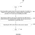
- FIG. 4 depicts a flowchart outlining the features of the invention in an exemplary embodiment of the invention.
- the method flowchart 400 describes a method being for operating an air handling unit (AHU) 102 at an effective static pressure setpoint in a HVAC system.
- the method flowchart 400 starts at step 402.
- a controller 216 of the AHU 102 may receive airflow setpoint values from each of a plurality of VAV units 106 to determine a combined airflow set point for the plurality of VAV units 106 of the AHU 102. This has been discussed in greater details in Figure 1 above.
- the controller 216 of the AHU 102 may determine an effective static pressure setpoint for the AHU 102 based on a relation between the combined airflow setpoint value and a static pressure represented by a system effect curve. This has been discussed in greater details in Figure 1 above.
- the controller 216 of the AHU 102 may operate the AHU 102 at the effective static pressure setpoint. This has been discussed in greater details in Figure 1 above. Then, the method flowchart 400 may end at 410.
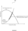
- Figure 5 depicts an exemplary graph 500 showing a relation between a fan characteristic curve, a system resistance curve and a system resistance curve with offset static pressure setpoint according to an exemplary embodiment of the invention.
- the system resistance curve and the system resistance curve with offset static pressure setpoint are determined and adjusted in order to operate the AHU 102 at the effective static pressure setpoint.
- the present invention is applicable in various industries/fields such as, but is not limited to, banking industry, hospitality industry, housing industry, building/construction industry, offices, universities, hospitals, colleges, homes and any such industry/field that is well known in the art and where HVAC systems are used.
- controller can refer to substantially any processor or computing processing unit or device comprising, but not limited to comprising, a direct digital control of a HVAC system, a zone controller of the HVAC system, single-core processors; single-processors with software multithread execution capability; multi-core processors; multi-core processors with software multithread execution capability; multi-core processors with hardware multithread technology; parallel platforms; and parallel platforms with distributed shared memory.
- a processor can refer to an integrated circuit, an application specific integrated circuit (ASIC), a digital signal processor (DSP), a field programmable gate array (FPGA), a programmable logic controller (PLC), a complex programmable logic device (CPLD), a discrete gate or transistor logic, discrete hardware components, or any combination thereof designed to perform the functions described herein.
- ASIC application specific integrated circuit
- DSP digital signal processor
- FPGA field programmable gate array
- PLC programmable logic controller
- CPLD complex programmable logic device
- a processor may also be implemented as a combination of computing processing units.
Landscapes
- Engineering & Computer Science (AREA)
- Chemical & Material Sciences (AREA)
- Combustion & Propulsion (AREA)
- Mechanical Engineering (AREA)
- General Engineering & Computer Science (AREA)
- Physics & Mathematics (AREA)
- Signal Processing (AREA)
- Fluid Mechanics (AREA)
- Fuzzy Systems (AREA)
- Mathematical Physics (AREA)
- Air Conditioning Control Device (AREA)
Claims (11)
- Verfahren (400), umfassend:- Empfangen (404) von Luftstromsollwerten von jeder einer Vielzahl von Einheiten mit variablem Luftvolumen (variable air volume, VAV) (106A, 106B, ..., 106N), um einen kombinierten Sollluftstrom für die Vielzahl von VAV-Einheiten einer Luftbehandlungseinheit (air handling unit, AHU) (102) zu bestimmen;- Bestimmen (406) eines effektiven statischen Solldrucks für die AHU basierend auf einer Beziehung zwischen dem kombinierten Luftstromsollwert und einem statischen Druck, der durch eine Systemeffektkurve dargestellt wird;- Betreiben (408) der AHU mit dem effektiven statischen Solldruck;- gekennzeichnet durch
Überwachen einer Klappenposition jeder VAV-Einheit (106A, 106B, ..., 106N) zum Bestimmen einer unterversorgten VAV-Einheit aus der Vielzahl von VAV-Einheiten und Berechnen des effektiven statischen Solldrucks der AHU (102);- Bestimmen eines Versatzes für die unterversorgte VAV-Einheit (106A, 106B, ..., 106N); und- Anpassen des Versatzes an den effektiven statischen Solldruck der AHU (102) für die unterversorgte VAV-Einheit. - Verfahren nach Anspruch 1, wobei die Anpassung des Versatzes an den effektiven statischen Solldruck der AHU (102) entweder durch Erhöhen oder Verringern des effektiven statischen Solldrucks der AHU erreicht wird.
- Verfahren nach Anspruch 1, ferner umfassend:automatisches Überwachen und Lernen eines Effekts der Anpassung des Versatzes an den effektiven statischen Solldruck der AHU (102) für einen effizienten Betrieb jeder der Vielzahl von VAV-Einheiten (106A, 106B, ..., 106N); und/oderBestimmen einer zweiten unterversorgten VAV-Einheit (106A, 106B, ..., 106N) und eines zweiten Versatzes basierend auf dem Effekt der Anpassung des Versatzes an den effektiven statischen Solldruck der AHU (102).
- Verfahren nach einem der vorhergehenden Ansprüche, wobei die Luftstromsollwerte jeder der Vielzahl von VAV-Einheiten (106A, 106B, ..., 106N) basierend auf Lastanforderung, einem Wert eines maximal zulässigen Sollluftstroms und einem Wert eines minimal zulässigen Sollluftstroms bestimmt werden; und/oder wobei die AHU (102) mit jeder der VAV-Einheiten (106A, 106B, ..., 106N) über einen oder mehrere Kanäle (104A, 104B, ..., 104N) verbunden ist.
- Verfahren nach einem der vorhergehenden Ansprüche, wobei der effektive statische Solldruck durch Variieren der Drehzahl eines Gebläses (202) erlangt wird, um den Bedarf des effektiven statischen Solldrucks zu decken; wobei optional das Gebläse gemäß der Systemeffektkurve betrieben wird, um einem Luftstrompfad mit der geringsten Impedanz zu folgen.
- Verfahren nach einem der vorhergehenden Ansprüche, ferner umfassend: Überwachen eines momentanen Werts einer vorhandenen Strategie zum Steuern des statischen Drucks zu einer definierten Intervallzeit zusammen mit aufgezeichneten Daten, um ihn mit einer Impedanzkurve zu vergleichen; und optional ferner umfassend: Gleichsetzen und Zeigen von Energieverlusten an einen Benutzer aufgrund des Nichtbefolgens der Impedanzkurve.
- System (100), umfassend:- eine Vielzahl von VAV-Einheiten mit variablem Luftvolumen (106A, 106B, ..., 106N), die dazu konfiguriert ist, Luftstromsollwerte zu bestimmen und die Luftstromsollwerte zu übermitteln; und- eine Luftbehandlungseinheit AHU (102), umfassend eine Steuerung (216), die zu Folgendem konfiguriert ist:Empfangen der Luftstromsollwerte von jeder der VAV-Einheiten;Bestimmen eines kombinierten Sollluftstroms für die Vielzahl von VAV-Einheiten der AHU;Bestimmen eines effektiven statischen Solldrucks basierend auf einer Beziehung zwischen dem kombinierten Luftstromsollwert und einem statischen Druck, der durch eine Systemeffektkurve dargestellt wird;Betreiben der AHU mit dem effektiven statischen Solldruck;dadurch gekennzeichnet, dass die Steuerung (216) ferner dazu konfiguriert ist, eine Klappenposition jeder VAV-Einheit (106A, 106B, ..., 106N) zu überwachen, um eine unterversorgte VAV-Einheit aus der Vielzahl von VAV-Einheiten zu bestimmen und den effektiven statischen Solldruck der AHU (102) zu berechnen;Bestimmen eines Versatzes für die unterversorgte VAV-Einheit (106A, 106B, ..., 106N); undAnpassen des Versatzes an den effektiven statischen Solldruck der AHU (102) für die unterversorgte VAV-Einheit.
- System nach Anspruch 7, wobei die Anpassung des Versatzes an den effektiven statischen Solldruck der AHU (102) entweder durch Erhöhen oder Verringern des effektiven statischen Solldrucks der AHU erreicht wird.
- System nach Anspruch 7, wobei die Steuerung (216) ferner zu Folgendem konfiguriert ist:automatisches Überwachen und Lernen eines Effekts der Anpassung des Versatzes an den effektiven statischen Solldruck der AHU (102) für einen effizienten Betrieb jeder der Vielzahl von VAV-Einheiten (106A, 106B, ..., 106N); und/oderBestimmen einer zweiten unterversorgten VAV-Einheit (106A, 106B, ..., 106N) und eines zweiten Versatzes basierend auf dem Effekt der Anpassung des Versatzes an den effektiven statischen Solldruck der AHU (102).
- System nach einem der Ansprüche 7 bis 9, wobei der effektive statische Solldruck durch Variieren der Drehzahl eines Gebläses (202) erlangt wird, um den Bedarf des effektiven statischen Solldrucks zu decken; wobei optional das Gebläse gemäß der Systemeffektkurve betrieben wird, um einem Luftstrompfad mit der geringsten Impedanz zu folgen.
- System nach einem der Ansprüche 7 bis 10, wobei die Luftstromsollwerte jeder der Vielzahl von VAV-Einheiten (106A, 106B, ..., 106N) basierend auf Lastanforderung, einem Wert eines maximal zulässigen Sollluftstroms und einem Wert eines minimal zulässigen Sollluftstroms bestimmt werden; und/oder wobei die AHU (102) mit jeder der VAV-Einheiten über einen oder mehrere Kanäle (104A, 104B, ..., 104N) verbunden ist.
Applications Claiming Priority (1)
| Application Number | Priority Date | Filing Date | Title |
|---|---|---|---|
| IN202011052896 | 2020-12-04 |
Publications (2)
| Publication Number | Publication Date |
|---|---|
| EP4008972A1 EP4008972A1 (de) | 2022-06-08 |
| EP4008972B1 true EP4008972B1 (de) | 2024-12-04 |
Family
ID=78821921
Family Applications (1)
| Application Number | Title | Priority Date | Filing Date |
|---|---|---|---|
| EP21212494.5A Active EP4008972B1 (de) | 2020-12-04 | 2021-12-06 | Verfahren und system zum betrieb einer luftbehandlungseinheit mit effektivem statischem druck |
Country Status (2)
| Country | Link |
|---|---|
| US (1) | US11835251B2 (de) |
| EP (1) | EP4008972B1 (de) |
Families Citing this family (1)
| Publication number | Priority date | Publication date | Assignee | Title |
|---|---|---|---|---|
| CN118946770A (zh) * | 2022-02-08 | 2024-11-12 | 凯普股份有限公司 | Vav扩散器控制 |
Family Cites Families (7)
| Publication number | Priority date | Publication date | Assignee | Title |
|---|---|---|---|---|
| US5863246A (en) | 1997-12-15 | 1999-01-26 | Carrier Corporation | Variable air volume control system |
| US6116095A (en) * | 1998-11-09 | 2000-09-12 | White Consolidated Industries, Inc. | Apparatus and method for measuring air flow from a duct system |
| US20060116067A1 (en) | 2004-12-01 | 2006-06-01 | Federspiel Clifford C | Method and apparatus for determining critical pressure of variable air volume heating, ventilating, and air-conditioning systems |
| US8235777B2 (en) * | 2005-05-03 | 2012-08-07 | Daniel Stanimirovic | Fully articulated and comprehensive air and fluid distribution, metering and control method and apparatus for primary movers, heat exchangers, and terminal flow devices |
| JP6877213B2 (ja) | 2017-03-31 | 2021-05-26 | アズビル株式会社 | Vavユニット制御装置及びvavユニットの制御方法 |
| US11416739B2 (en) * | 2018-01-29 | 2022-08-16 | Lawrence Livermore National Security, Llc | Optimization control technology for building energy conservation |
| US20220058497A1 (en) * | 2020-08-21 | 2022-02-24 | Siemens Industry, Inc. | Systems and methods for fault diagnostics in building automation systems |
-
2021
- 2021-11-24 US US17/534,755 patent/US11835251B2/en active Active
- 2021-12-06 EP EP21212494.5A patent/EP4008972B1/de active Active
Also Published As
| Publication number | Publication date |
|---|---|
| EP4008972A1 (de) | 2022-06-08 |
| US20220178578A1 (en) | 2022-06-09 |
| US11835251B2 (en) | 2023-12-05 |
Similar Documents
| Publication | Publication Date | Title |
|---|---|---|
| US7177776B2 (en) | System and method for developing and processing building system control solutions | |
| US7886986B2 (en) | Building, ventilation system, and recovery device control | |
| US5791408A (en) | Air handling unit including control system that prevents outside air from entering the unit through an exhaust air damper | |
| CN100523666C (zh) | 供暖、通风与空调系统中区域风门的故障检测方法和hvac系统 | |
| US4754919A (en) | Air conditioning apparatus | |
| US8112181B2 (en) | Automatic mold and fungus growth inhibition system and method | |
| US4635445A (en) | Air-conditioner | |
| US9612030B2 (en) | Arrangement and method for automatically determined time constant for a control device | |
| US8596079B2 (en) | Intelligent venting | |
| US20230011991A1 (en) | Indoor air quality for variable air volume system | |
| Kaam et al. | Time-averaged ventilation for optimized control of variable-air-volume systems | |
| US20100198370A1 (en) | Asymmetrical control system and method for energy savings in buildings | |
| US20060116067A1 (en) | Method and apparatus for determining critical pressure of variable air volume heating, ventilating, and air-conditioning systems | |
| CN111780328B (zh) | 一种送风控制方法、装置及空调设备 | |
| EP4119856A1 (de) | Innenraumluftqualität für ein system mit variablem luftvolumen | |
| JP3194220B2 (ja) | Vav制御システム | |
| US11835251B2 (en) | Method and a system for operating an air handling unit at effective static pressure | |
| US20230160599A1 (en) | Variable speed airflow zone board | |
| US11835250B2 (en) | Method and a system for performing calibration of variable air volume (VAV) units | |
| KR100749175B1 (ko) | 공조 시스템에서의 분류형 규칙기반 방식의 단일부위 고장검출 및 진단 방법과 이를 이용한 장치 | |
| JP3468058B2 (ja) | 空調方法及び空調システム | |
| KR100792714B1 (ko) | 공조 시스템에서의 상세 분류형 규칙기반 방식의 단일부위고장 검출 및 진단 방법 | |
| US20240384887A1 (en) | Method and system for controlling a fresh air intake of an air handling unit of an hvac system | |
| JP3177718B2 (ja) | 空調制御装置 | |
| JPH0420736A (ja) | 空気調和装置 |
Legal Events
| Date | Code | Title | Description |
|---|---|---|---|
| PUAI | Public reference made under article 153(3) epc to a published international application that has entered the european phase |
Free format text: ORIGINAL CODE: 0009012 |
|
| STAA | Information on the status of an ep patent application or granted ep patent |
Free format text: STATUS: THE APPLICATION HAS BEEN PUBLISHED |
|
| AK | Designated contracting states |
Kind code of ref document: A1 Designated state(s): AL AT BE BG CH CY CZ DE DK EE ES FI FR GB GR HR HU IE IS IT LI LT LU LV MC MK MT NL NO PL PT RO RS SE SI SK SM TR |
|
| STAA | Information on the status of an ep patent application or granted ep patent |
Free format text: STATUS: REQUEST FOR EXAMINATION WAS MADE |
|
| 17P | Request for examination filed |
Effective date: 20221208 |
|
| RBV | Designated contracting states (corrected) |
Designated state(s): AL AT BE BG CH CY CZ DE DK EE ES FI FR GB GR HR HU IE IS IT LI LT LU LV MC MK MT NL NO PL PT RO RS SE SI SK SM TR |
|
| GRAP | Despatch of communication of intention to grant a patent |
Free format text: ORIGINAL CODE: EPIDOSNIGR1 |
|
| STAA | Information on the status of an ep patent application or granted ep patent |
Free format text: STATUS: GRANT OF PATENT IS INTENDED |
|
| INTG | Intention to grant announced |
Effective date: 20240625 |
|
| GRAS | Grant fee paid |
Free format text: ORIGINAL CODE: EPIDOSNIGR3 |
|
| GRAA | (expected) grant |
Free format text: ORIGINAL CODE: 0009210 |
|
| STAA | Information on the status of an ep patent application or granted ep patent |
Free format text: STATUS: THE PATENT HAS BEEN GRANTED |
|
| AK | Designated contracting states |
Kind code of ref document: B1 Designated state(s): AL AT BE BG CH CY CZ DE DK EE ES FI FR GB GR HR HU IE IS IT LI LT LU LV MC MK MT NL NO PL PT RO RS SE SI SK SM TR |
|
| REG | Reference to a national code |
Ref country code: CH Ref legal event code: EP |
|
| REG | Reference to a national code |
Ref country code: DE Ref legal event code: R096 Ref document number: 602021022786 Country of ref document: DE |
|
| REG | Reference to a national code |
Ref country code: IE Ref legal event code: FG4D |
|
| REG | Reference to a national code |
Ref country code: LT Ref legal event code: MG9D |
|
| REG | Reference to a national code |
Ref country code: NL Ref legal event code: MP Effective date: 20241204 |
|
| PG25 | Lapsed in a contracting state [announced via postgrant information from national office to epo] |
Ref country code: HR Free format text: LAPSE BECAUSE OF FAILURE TO SUBMIT A TRANSLATION OF THE DESCRIPTION OR TO PAY THE FEE WITHIN THE PRESCRIBED TIME-LIMIT Effective date: 20241204 |
|
| PG25 | Lapsed in a contracting state [announced via postgrant information from national office to epo] |
Ref country code: FI Free format text: LAPSE BECAUSE OF FAILURE TO SUBMIT A TRANSLATION OF THE DESCRIPTION OR TO PAY THE FEE WITHIN THE PRESCRIBED TIME-LIMIT Effective date: 20241204 |
|
| PG25 | Lapsed in a contracting state [announced via postgrant information from national office to epo] |
Ref country code: BG Free format text: LAPSE BECAUSE OF FAILURE TO SUBMIT A TRANSLATION OF THE DESCRIPTION OR TO PAY THE FEE WITHIN THE PRESCRIBED TIME-LIMIT Effective date: 20241204 |
|
| PG25 | Lapsed in a contracting state [announced via postgrant information from national office to epo] |
Ref country code: ES Free format text: LAPSE BECAUSE OF FAILURE TO SUBMIT A TRANSLATION OF THE DESCRIPTION OR TO PAY THE FEE WITHIN THE PRESCRIBED TIME-LIMIT Effective date: 20241204 |
|
| PG25 | Lapsed in a contracting state [announced via postgrant information from national office to epo] |
Ref country code: NO Free format text: LAPSE BECAUSE OF FAILURE TO SUBMIT A TRANSLATION OF THE DESCRIPTION OR TO PAY THE FEE WITHIN THE PRESCRIBED TIME-LIMIT Effective date: 20250304 |
|
| PG25 | Lapsed in a contracting state [announced via postgrant information from national office to epo] |
Ref country code: LV Free format text: LAPSE BECAUSE OF FAILURE TO SUBMIT A TRANSLATION OF THE DESCRIPTION OR TO PAY THE FEE WITHIN THE PRESCRIBED TIME-LIMIT Effective date: 20241204 Ref country code: GR Free format text: LAPSE BECAUSE OF FAILURE TO SUBMIT A TRANSLATION OF THE DESCRIPTION OR TO PAY THE FEE WITHIN THE PRESCRIBED TIME-LIMIT Effective date: 20250305 |
|
| PG25 | Lapsed in a contracting state [announced via postgrant information from national office to epo] |
Ref country code: RS Free format text: LAPSE BECAUSE OF FAILURE TO SUBMIT A TRANSLATION OF THE DESCRIPTION OR TO PAY THE FEE WITHIN THE PRESCRIBED TIME-LIMIT Effective date: 20250304 |
|
| PG25 | Lapsed in a contracting state [announced via postgrant information from national office to epo] |
Ref country code: NL Free format text: LAPSE BECAUSE OF FAILURE TO SUBMIT A TRANSLATION OF THE DESCRIPTION OR TO PAY THE FEE WITHIN THE PRESCRIBED TIME-LIMIT Effective date: 20241204 |
|
| REG | Reference to a national code |
Ref country code: AT Ref legal event code: MK05 Ref document number: 1748554 Country of ref document: AT Kind code of ref document: T Effective date: 20241204 |
|
| PG25 | Lapsed in a contracting state [announced via postgrant information from national office to epo] |
Ref country code: SM Free format text: LAPSE BECAUSE OF FAILURE TO SUBMIT A TRANSLATION OF THE DESCRIPTION OR TO PAY THE FEE WITHIN THE PRESCRIBED TIME-LIMIT Effective date: 20241204 |
|
| PG25 | Lapsed in a contracting state [announced via postgrant information from national office to epo] |
Ref country code: PL Free format text: LAPSE BECAUSE OF FAILURE TO SUBMIT A TRANSLATION OF THE DESCRIPTION OR TO PAY THE FEE WITHIN THE PRESCRIBED TIME-LIMIT Effective date: 20241204 |
|
| PG25 | Lapsed in a contracting state [announced via postgrant information from national office to epo] |
Ref country code: IS Free format text: LAPSE BECAUSE OF FAILURE TO SUBMIT A TRANSLATION OF THE DESCRIPTION OR TO PAY THE FEE WITHIN THE PRESCRIBED TIME-LIMIT Effective date: 20250404 |
|
| PG25 | Lapsed in a contracting state [announced via postgrant information from national office to epo] |
Ref country code: PT Free format text: LAPSE BECAUSE OF FAILURE TO SUBMIT A TRANSLATION OF THE DESCRIPTION OR TO PAY THE FEE WITHIN THE PRESCRIBED TIME-LIMIT Effective date: 20250404 |
|
| PG25 | Lapsed in a contracting state [announced via postgrant information from national office to epo] |
Ref country code: EE Free format text: LAPSE BECAUSE OF FAILURE TO SUBMIT A TRANSLATION OF THE DESCRIPTION OR TO PAY THE FEE WITHIN THE PRESCRIBED TIME-LIMIT Effective date: 20241204 |
|
| PG25 | Lapsed in a contracting state [announced via postgrant information from national office to epo] |
Ref country code: AT Free format text: LAPSE BECAUSE OF FAILURE TO SUBMIT A TRANSLATION OF THE DESCRIPTION OR TO PAY THE FEE WITHIN THE PRESCRIBED TIME-LIMIT Effective date: 20241204 Ref country code: RO Free format text: LAPSE BECAUSE OF FAILURE TO SUBMIT A TRANSLATION OF THE DESCRIPTION OR TO PAY THE FEE WITHIN THE PRESCRIBED TIME-LIMIT Effective date: 20241204 |
|
| PG25 | Lapsed in a contracting state [announced via postgrant information from national office to epo] |
Ref country code: SK Free format text: LAPSE BECAUSE OF FAILURE TO SUBMIT A TRANSLATION OF THE DESCRIPTION OR TO PAY THE FEE WITHIN THE PRESCRIBED TIME-LIMIT Effective date: 20241204 |
|
| PG25 | Lapsed in a contracting state [announced via postgrant information from national office to epo] |
Ref country code: CZ Free format text: LAPSE BECAUSE OF FAILURE TO SUBMIT A TRANSLATION OF THE DESCRIPTION OR TO PAY THE FEE WITHIN THE PRESCRIBED TIME-LIMIT Effective date: 20241204 |
|
| PG25 | Lapsed in a contracting state [announced via postgrant information from national office to epo] |
Ref country code: IT Free format text: LAPSE BECAUSE OF FAILURE TO SUBMIT A TRANSLATION OF THE DESCRIPTION OR TO PAY THE FEE WITHIN THE PRESCRIBED TIME-LIMIT Effective date: 20241204 |
|
| REG | Reference to a national code |
Ref country code: CH Ref legal event code: PL |
|
| PG25 | Lapsed in a contracting state [announced via postgrant information from national office to epo] |
Ref country code: LU Free format text: LAPSE BECAUSE OF NON-PAYMENT OF DUE FEES Effective date: 20241206 |
|
| REG | Reference to a national code |
Ref country code: DE Ref legal event code: R097 Ref document number: 602021022786 Country of ref document: DE |
|
| PG25 | Lapsed in a contracting state [announced via postgrant information from national office to epo] |
Ref country code: SE Free format text: LAPSE BECAUSE OF FAILURE TO SUBMIT A TRANSLATION OF THE DESCRIPTION OR TO PAY THE FEE WITHIN THE PRESCRIBED TIME-LIMIT Effective date: 20241204 |
|
| PG25 | Lapsed in a contracting state [announced via postgrant information from national office to epo] |
Ref country code: MC Free format text: LAPSE BECAUSE OF FAILURE TO SUBMIT A TRANSLATION OF THE DESCRIPTION OR TO PAY THE FEE WITHIN THE PRESCRIBED TIME-LIMIT Effective date: 20241204 |
|
| REG | Reference to a national code |
Ref country code: BE Ref legal event code: MM Effective date: 20241231 |
|
| PG25 | Lapsed in a contracting state [announced via postgrant information from national office to epo] |
Ref country code: DK Free format text: LAPSE BECAUSE OF FAILURE TO SUBMIT A TRANSLATION OF THE DESCRIPTION OR TO PAY THE FEE WITHIN THE PRESCRIBED TIME-LIMIT Effective date: 20241204 |
|
| PLBE | No opposition filed within time limit |
Free format text: ORIGINAL CODE: 0009261 |
|
| STAA | Information on the status of an ep patent application or granted ep patent |
Free format text: STATUS: NO OPPOSITION FILED WITHIN TIME LIMIT |
|
| PG25 | Lapsed in a contracting state [announced via postgrant information from national office to epo] |
Ref country code: BE Free format text: LAPSE BECAUSE OF NON-PAYMENT OF DUE FEES Effective date: 20241231 |
|
| PG25 | Lapsed in a contracting state [announced via postgrant information from national office to epo] |
Ref country code: CH Free format text: LAPSE BECAUSE OF NON-PAYMENT OF DUE FEES Effective date: 20241231 |
|
| PG25 | Lapsed in a contracting state [announced via postgrant information from national office to epo] |
Ref country code: IE Free format text: LAPSE BECAUSE OF NON-PAYMENT OF DUE FEES Effective date: 20241206 |
|
| 26N | No opposition filed |
Effective date: 20250905 |
|
| PGFP | Annual fee paid to national office [announced via postgrant information from national office to epo] |
Ref country code: DE Payment date: 20251126 Year of fee payment: 5 |
|
| PGFP | Annual fee paid to national office [announced via postgrant information from national office to epo] |
Ref country code: FR Payment date: 20251120 Year of fee payment: 5 |
|
| PG25 | Lapsed in a contracting state [announced via postgrant information from national office to epo] |
Ref country code: CY Free format text: LAPSE BECAUSE OF FAILURE TO SUBMIT A TRANSLATION OF THE DESCRIPTION OR TO PAY THE FEE WITHIN THE PRESCRIBED TIME-LIMIT; INVALID AB INITIO Effective date: 20211206 |