EP4008817A1 - Procédé et dispositif pour déterminer un paramètre de mouvement d'une pince - Google Patents
Procédé et dispositif pour déterminer un paramètre de mouvement d'une pince Download PDFInfo
- Publication number
- EP4008817A1 EP4008817A1 EP20212103.4A EP20212103A EP4008817A1 EP 4008817 A1 EP4008817 A1 EP 4008817A1 EP 20212103 A EP20212103 A EP 20212103A EP 4008817 A1 EP4008817 A1 EP 4008817A1
- Authority
- EP
- European Patent Office
- Prior art keywords
- transmission part
- gripper
- drive element
- angular position
- marker
- Prior art date
- Legal status (The legal status is an assumption and is not a legal conclusion. Google has not performed a legal analysis and makes no representation as to the accuracy of the status listed.)
- Pending
Links
- 238000000034 method Methods 0.000 title claims abstract description 33
- 230000005540 biological transmission Effects 0.000 claims abstract description 314
- 238000009941 weaving Methods 0.000 claims abstract description 105
- 230000007246 mechanism Effects 0.000 claims abstract description 87
- 230000008859 change Effects 0.000 claims abstract description 48
- 230000010355 oscillation Effects 0.000 claims abstract description 39
- 239000003550 marker Substances 0.000 claims description 88
- 238000004590 computer program Methods 0.000 claims description 4
- 230000001133 acceleration Effects 0.000 description 9
- 230000010363 phase shift Effects 0.000 description 8
- 239000004744 fabric Substances 0.000 description 7
- 230000008901 benefit Effects 0.000 description 4
- 230000001939 inductive effect Effects 0.000 description 3
- 230000003287 optical effect Effects 0.000 description 3
- 230000009467 reduction Effects 0.000 description 3
- 230000003247 decreasing effect Effects 0.000 description 2
- 230000014509 gene expression Effects 0.000 description 2
- 238000003825 pressing Methods 0.000 description 2
- 230000001360 synchronised effect Effects 0.000 description 2
- 230000003213 activating effect Effects 0.000 description 1
- 230000001419 dependent effect Effects 0.000 description 1
- 238000001514 detection method Methods 0.000 description 1
- 239000012530 fluid Substances 0.000 description 1
- 230000006870 function Effects 0.000 description 1
- 238000004519 manufacturing process Methods 0.000 description 1
- 238000005259 measurement Methods 0.000 description 1
- 230000000630 rising effect Effects 0.000 description 1
Images


Classifications
-
- D—TEXTILES; PAPER
- D03—WEAVING
- D03D—WOVEN FABRICS; METHODS OF WEAVING; LOOMS
- D03D47/00—Looms in which bulk supply of weft does not pass through shed, e.g. shuttleless looms, gripper shuttle looms, dummy shuttle looms
- D03D47/27—Drive or guide mechanisms for weft inserting
- D03D47/275—Drive mechanisms
Definitions
- the invention relates to a method and a device for determining a movement parameter of a gripper in a gripper weaving machine.
- the invention further relates to a computer program product comprising instructions which, when the program is executed by a computer, cause the computer to carry out the method for determining a movement parameter of a gripper in a gripper weaving machine, and to a data processing device comprising a processor unit adapted to perform the method for determining a movement parameter of a gripper in a gripper weaving machine.
- gripper weaving machines typically comprise two grippers, one of which is known as the drawing gripper and carries a weft thread from one end of the weaving machine to a changeover position at or near to the middle of the weaving machine, and the other one is known as the receiving gripper, which accepts the weft thread from the drawing gripper at the changeover position and carries the weft thread to the other end of the weaving machine.
- Each gripper is fixed to a rapier, which rapier is driven by a rapier drive wheel.
- rapiers can be flexible gripper bands or rigid gripper rods.
- US 5,853,032 shows another transmission mechanism for causing an oscillating movement of a gear segment driving a rapier drive wheel, wherein when setting an amplitude of the oscillation, one of the two extreme positions of the oscillation, which is associated with a changeover position of a gripper driven by the rapier drive wheel, is maintained.
- EP 565885 A shows another transmission mechanism for causing an oscillating movement of a transmission part such as a gear segment for driving a rapier drive wheel, wherein an amplitude of an oscillation of the transmission part is settable.
- This transmission mechanism comprises a cam mechanism for driving the transmission part via a crank mechanism.
- US 4052906 or WO 2005/078317 show another transmission mechanism for causing an oscillating movement of a transmission part such as a slider for driving a rapier drive wheel, wherein an amplitude of an oscillation of the transmission part is settable.
- This transmission mechanism comprises a crank mechanism and a threaded spindle driven by the crank mechanism for driving the transmission part back and forth.
- DE 100 33 641 A1 also shows a crank mechanism for causing an oscillating movement of a gear segment driving a rapier drive wheel, wherein for setting an amplitude of the oscillation of the gear segment a connecting rod of the crank mechanism is coupled to the gear segment in an adjustable position by means of an adjusting device, which adjusting device is equipped with a scale.
- a method for determining a movement parameter of a gripper in a gripper weaving machine wherein the gripper can be driven to move back and forth using a transmission part, wherein a drive element rotating with a drive shaft of the gripper weaving machine is drivingly coupled via a transmission mechanism to the transmission part, wherein the transmission part can be driven by the drive element to oscillate between extreme transmission part positions, and wherein an amplitude of an oscillation of the transmission part is adjustable by setting the transmission mechanism, and wherein the method comprises the steps of determining a change in an angular position of the drive element when moving the transmission part over a defined range, and determining the amplitude of the oscillation of the transmission part based on the determined change in the angular position of the drive element.
- defined range is used to describe a range over which the transmission part is moved upon a movement of the transmission part in one direction between two distinct transmission part positions as well as a range over which the transmission part is moved upon a movement of the transmission part back and forth from a transmission part position and back to this or any other transmission part position.
- the transmission part is coupled to a rapier drive wheel with a fixed transmission ratio between the movement of the transmission part and the movement of the rapier drive wheel. It has been the findings of the inventor that there is a determinable relation between movement parameters of the gripper and the transmission ratio of the transmission mechanism between a rotational movement of the drive element rotating with the drive shaft and a movement of the transmission part oscillating between extreme transmission part positions, which determinable relation is not influenced by any individually chosen extreme position of the gripper, and that when this transmission ratio of the transmission mechanism is determined based on a change in the angular position of the drive element when moving the transmission part over a defined range, a determination of the transmission ratio of the transmission mechanism is possible that is independent of any phase shift between the movement of the transmission part and the drive shaft of the weaving machine.
- An advantage of the invention is that the determination of the amplitude of the oscillation of the transmission part driving the gripper is possible while the rapier driving the gripper is decoupled from the transmission part or even while no rapier is present in the gripper weaving machine.
- An accurate determination of the amplitude of the oscillation of the transmission part driving the gripper also allows to determine the movement profile of the gripper and to maximize the weaving speed of the gripper weaving machine, as the weaving speed of the gripper weaving machine is mainly limited by the movement profile of the grippers defined by movement parameters, such as the movement stroke, the movement speed and/or the movement acceleration of the grippers.
- the allowable weaving speed of the gripper weaving machine, and also the movement speed of the gripper, the movement stroke of the gripper and the movement acceleration of the gripper can be determined based on information about transmission part positions versus angular positions of the drive element. This information can be calculated based on geometric parameters of the transmission mechanism. This information can also be stored in a memory for different amplitudes of the oscillation of the transmission part.
- information about the relation between a movement parameter of the gripper, the weaving speed of the gripper weaving machine and the transmission ratio between a rotational movement of the drive element rotating with the drive shaft and a movement of the transmission part oscillating between extreme transmission part positions can be stored in a memory for different amplitudes of the oscillation of the transmission part, in particular for different movement strokes of the gripper.
- the transmission mechanism is a crank mechanism having a crank that is fixed in an adjustable eccentric position to the drive element
- the transmission ratio can be determined by the eccentric position of the crank with respect to the drive element, dimensions of the elements of the transmission mechanism and other geometric parameters.
- the information can be stored in a memory of a processor unit.
- the method for determining a movement parameter of a gripper comprises a step of accessing said memory.
- a marker is provided on the transmission part for marking a boundary of the defined range
- a sensor device is provided, which is arranged fixed in position opposite the transmission part, and which is adapted for sensing a presence or an absence of the marker.
- the presence of the marker is identified when the transmission part reaches or passes a position, in which the marker is within a sensing region of the sensor device, and/or the absence of the marker is identified when the transmission part passes or leaves said position, in which the marker is within a sensing region of the sensor device. This allows capturing an angular position of the drive element when sensing the presence or the absence of the marker.
- a first marker is provided on the transmission part for marking a first boundary of the defined range and a second marker is provided on the transmission part for marking a second boundary of the defined range
- the method comprises moving the transmission part such that the first marker and the second marker each pass a sensor device arranged fixed in position opposite the transmission part, capturing a first angular position of the drive element when the first marker passes the sensor device and capturing a second angular position of the drive element when the second marker passes the sensor device, and determining the change in the angular position of the drive element from the captured first angular position and the captured second angular position, wherein in particular the first angular position of the drive element and the second angular position of the drive element are captured when moving the transmission part in one direction.
- the transmission part is moved in opposite directions when two of the markers pass the sensor device and the first position and the second position are captured.
- the method for determining the amplitude of the oscillation of the transmission part, and also the movement stroke of the gripper comprises moving the transmission part back and forth, such that one marker passes twice a sensor device arranged fixed in position opposite the transmission part, wherein the method further comprises capturing a first angular position of the drive element when said marker passes the sensor device upon moving in a first direction and capturing a second angular position of the drive element when said marker passes the sensor device upon moving in a second direction opposite to the first direction, and determining the change in the angular position of the drive element from the captured first angular position and the captured second angular position.
- the defined range is delimited by one selected position due to the fact, that the transmission part is moved past said selected position into an extreme position and back from the extreme position past said selected position.
- the defined range of the transmission part is delimited by a selected position marked by one marker and a reference position of the transmission part associated with one reference angular position of the drive element, which is identical for all settings of the amplitude of the oscillation of the transmission part, and known in advance.
- a change in the angular position of the drive element can be determined based on one captured angular position of the drive element when the marker passes the sensor device and the reference angular position of the drive element.
- the determination of the amplitude of the oscillation of the transmission part, and also the movement stroke of the gripper is independent of any phase shift between an oscillation movement of the transmission part and a rotation of the drive shaft of the weaving machine, which phase shift could influence the reference angular position.
- the change in the angular position of the drive element is determined from the captured first angular position, the captured second angular position, and stored information about a transmission part position versus the angular position of the drive element for different movement strokes of the gripper.
- the information about the transmission part position versus the angular position of the drive element can be determined in advance for different movement strokes of the gripper based on information about dimensions of the elements of the crank mechanism and other geometric parameters.
- the information is stored for example in a memory of a processor unit.
- a selected gripper position of the gripper driven by the transmission part is captured using a gripper position sensor device.
- the gripper position sensor device in one embodiment is adapted and arranged to capture the position of the gripper directly.
- a gripper position sensor device in particular a proximity sensor device, is mounted in a stationary position near the gripper path, for example in a rapier guide, to detect when the gripper is in a defined position in relation to the fabric, and in relation to the drive element rotating with the drive shaft of the weaving machine.
- the gripper position sensor device is adapted and arranged to capture the position of the gripper indirectly, by capturing a position of an element drivingly coupled to the gripper, for example by capturing an angular position of a rapier drive wheel.
- an actual gripper position of the gripper is determined using the captured selected gripper position, the angular position of the drive element when capturing the selected gripper position and the movement stroke of the gripper.
- a computer program product comprising instructions which, when the program is executed by a computer, cause the computer to carry out the method as described above is provided.
- a data processing device comprising a processor unit adapted to perform the method as described above is provided.
- a device for determining a movement parameter of a gripper in a gripper weaving machine wherein the gripper can be driven to move back and forth using a transmission part, wherein a drive element rotating with a drive shaft of the gripper weaving machine is drivingly coupled via a transmission mechanism to the transmission part, wherein the transmission part can be driven by the drive element to oscillate between extreme transmission part positions, and wherein an amplitude of an oscillation of the transmission part is adjustable by setting the transmission mechanism, and wherein the device comprises a processor unit adapted to determine a change in an angular position of the drive element when moving the transmission part over a defined range, and to determine the amplitude of the oscillation of the transmission part based on the determined change in the angular position of the drive element.
- the device comprises a first marker provided on the transmission part for marking a first boundary of the defined range, a second marker provided on the transmission part for marking a second boundary of the defined angular range, and a sensor device arranged fixed in position opposite the transmission part, wherein the processor unit is adapted to capture a first angular position of the drive element when the first marker passes the sensor device upon moving in a first direction and to capture a second angular position of the drive element when the second marker passes the sensor device upon moving in said direction or in a direction opposite to said direction, and to determine the change in the angular position of the drive element from the captured first angular position and the captured second angular position.
- a distance between the first marker and the second marker is maximized in consideration of at least smaller amplitudes of movement of the transmission part.
- the distance between the first marker and the second marker is chosen as large as possible for an accurate determination of a change in the angular position of the drive element, but such that for the smallest possible amplitude, both markers are still within a movement range of the transmission part.
- the amplitude of the oscillation of the transmission part is determined using only one of the first marker and the second marker.
- the device comprises one marker provided on the transmission part for marking a boundary of the defined range, and a sensor device arranged fixed in position opposite the transmission part, wherein the processor unit is adapted to capture a first angular position of the drive element when said marker passes the sensor device upon moving in a first direction and to capture a second angular position of the drive element when said marker passes the sensor device upon moving in a second direction opposite to the first direction, and to determine the change in the angular position of the drive element from the captured first angular position of the drive element and the captured second angular position of the drive element.
- the processor unit comprises a memory in which information about a transmission part position versus the angular position of the drive element is stored for different movement strokes of the gripper, wherein the processor unit is adapted to determine the change in the angular position of the drive element from the captured first angular position, the captured second angular position and the stored information.
- the memory in one embodiment forms a physical entity with the processor unit. In other embodiments, the memory is a distinct unit.
- the sensor device for detecting the markers is a magnetic proximity sensor device, wherein the first marker and the second marker are magnets.
- the sensor device is a proximity sensor device, in particular selected from the group comprising a capacitive proximity sensor device, an inductive proximity sensor and an optical proximity sensor device, wherein the first marker and the second marker are selected from the group comprising a recess, a cutout, a protrusion.
- a capacitive proximity sensor device such an inductive proximity sensor or such an optical proximity sensor device are inexpensive devices, which can be fixed to a frame of a gripper drive system of the weaving machine at a fabrication stage, thereby ensuring that the sensor device is correctly mounted.
- the proximity sensor device can for example be a Hall sensor.
- the transmission part is a gear segment that rotationally moves back and forth about a gear segment axis to oscillate between the extreme transmission part positions, wherein the defined range is a defined angular range over which the gear segment can be rotationally moved.
- a gear segment is a robust element, which moves in a plane about an axis and is not subjected to vibrations. This allows for a precise detection of each marker by the sensor device.
- edges of the marker when the transmission part is a gear segment, edges of the marker, in particular edges of the first marker and edges of the second marker, extend in a radial direction with respect to a gear segment axis. This arrangement ensures that even with a small misalignment of the sensor device in the radial direction, the sensor device is able to always give a signal when the gear segment extends at a certain angular position.
- a gripper position sensor device for capturing a selected gripper position of the gripper driven by the transmission part, wherein the processor unit is adapted to determine an actual gripper position of the gripper using the captured selected gripper position, the angular position of the drive element when capturing the selected gripper position, and the amplitude of the oscillation of the transmission part, in particular the movement stroke of the gripper.
- a weaving machine with a data processing device as described above and/or with a device as described above is provided.
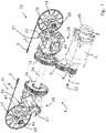
- Fig. 1 shows a drive system 1 for moving back and forth a drawing gripper 3 fixed to a first rapier 2 and a receiving gripper 5 fixed to a second rapier 4.
- the drawing gripper 3 and the receiving gripper 5 are also referred to together as grippers or individually as gripper.
- the rapiers 2, 4 can be a flexible gripper band or a more rigid gripper rod, or any other type of rapier to be used in a gripper weaving machine.
- the drive system 1 may be used in a weaving machine, in particular in a gripper weaving machine.
- gripper weaving machines as also explained in WO 2011/120820 of the applicant, the drawing gripper 3 and the receiving gripper 5 are intended to move into and out of a shed formed by planes of warp threads, which converge at the location of the beat-up line of a fabric.
- the drive system 1 For moving the grippers 3, 5 into and out of the shed, the drive system 1 comprises a first drive mechanism 10, which drives a first rapier drive wheel 14 for the first rapier 2, and a second drive mechanism 11, which drives a second rapier drive wheel 15 for the second rapier 4, wherein an oscillation of the first rapier drive wheel 14 and an oscillation of the second rapier drive wheel 15 allow the drawing gripper 3 and the receiving gripper 5, respectively, to reciprocate between an outer reversing point situated outside the shed and an inner reversing point situated inside the shed.
- the first drive mechanism 10 and the second drive mechanism 11 each comprise a drive element 12, 26 in the form of a gear wheel, a transmission mechanism 24, 25, a transmission part 31, 32 in the form of a gear segment 22, 47, and the rapier drive wheel 14, 15.
- the transmission mechanism 24, 25 is a crank mechanism
- the gear segment 22, 47 is driving the rapier drive wheel 14, 15.
- the drive system 1 shown in Fig. 1 comprises a drive motor 6 having a drive shaft 7.
- the drive motor 6 can drive the first drive element 12 to rotate in one direction via a first gear wheel 8 coupled to the drive shaft 7 and an intermediate second gear wheel 9.
- the first drive element 12 is connected to the second drive element 26 via a shaft 54 that is further named the main shaft of the weaving machine.
- the first drive mechanism 10 is driven by the drive motor 6 via the gear wheels 8 and 9, while the second drive mechanism 11 is driven by the drive motor 6 via the gear wheels 8 and 9, the drive element 12, and the shaft 54.
- two synchronized distinct drive motors are provided each driving an associated drive element 12, 26.
- the drive elements 12, 26 are driven via the drive motor 6 to rotate with the shaft 54 of the weaving machine, i.e. the drive elements 12, 26 are driven to make one full rotation per each weaving cycle, wherein in one embodiment the rotation of the drive elements 12, 26 is phase-shifted such that the drawing gripper 3 and/or the receiving gripper 5 reaches the inner reversing point and the outer reversing point slightly before or after the shaft 54 reaches 0° and 180°.
- the first drive element 12 is drivingly coupled via the first transmission mechanism 24 to the first transmission part 31 driving a rapier drive wheel 14.
- the first transmission part 31 is gear segment 22 that can be driven by the first drive element 12 to oscillate about a gear segment axis 45.
- the first transmission part 31 drives the first rapier drive wheel 14 for the drawing gripper 3 via a transmission 18, so that the first rapier drive wheel 14 oscillates about its rotation axis 48.
- the second drive element 26 is drivingly coupled via the second transmission mechanism 25 to the second transmission part 47 driving a rapier drive wheel 14.
- the second transmission part 32 is a gear segment 47 that can be driven by the second drive element 26 to oscillate about a gear segment axis 51.
- the second transmission part 32 drives the second rapier drive wheel 15 for the receiving gripper 5 via a transmission 27, so that the second rapier drive wheel 15 oscillates about its rotation axis 49.
- an angular position of the drive element 12 is captured using an angular sensor 55, such as an encoder provided on the drive shaft 7, for example an encoder that is able to generate 360 signals for each rotation of the drive shaft 7 driving the weaving machine.
- the angular sensor 55 can be connected to a processor unit 61 as schematically shown in Fig. 2 .
- the angular sensor can also be provided on the shaft 54 of the gripper weaving machine.
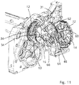
- the first drive mechanism 10 is shown in more detail in Figs. 2 to 6 .
- Fig. 2 further a rapier guide 37 arranged near the shed and a rapier guide 38 arranged near the rapier drive wheel 14 are shown.
- the transmission mechanism 24 comprises a crank 13 connected to the drive element 12, a fork element 16 rotatably mounted to the crank 13, and a cross element 17 rotatably mounted to the fork element 16.
- the transmission part 31 is a gear segment 22 that is fixedly connected to the cross element 17 and oscillates together with the cross element 17 about the gear segment axis 45.
- the transmission part 31 drives the drive wheel 14 for the gripper 3 via a transmission 18, which in the embodiment shown is a gear wheel transmission.
- the transmission part 31 is coupled to the rapier drive wheel 14, so that the rapier drive wheel 14 can move together or can move synchronized with the transmission part 31, in other words there is a fixed transmission ratio between the movement of the transmission part 31 and the movement of the rapier drive wheel 14.
- the drive wheel 14 is detachably fastened to the transmission 18 by a fastening device 35.
- the fastening device 35 comprises a disc 90 to which the drive wheel 14 is fixed by bolts 91 (only shown in Figs. 2 to 4 ).
- the disc 90 can be fixed to the shaft 50 in any angular position of the drive wheel 14 using a pressing ring 88 and bolts 92. In this way the disc 90 to which the drive wheel 14 is attached is pressed between the shaft 50 and the pressing ring 88. When the bolts 92 are loosened the disc 90 with the rapier wheel 14 can rotate along the shaft 50, so that the angular position of the rapier wheel 14 with respect to the shaft 50 can be adjusted.
- the crank 13 is moveably mounted to the drive element 12 via a bearing half 19, which cooperates with a respective part of the crank 13.
- the crank 13 can be moved with respect to the drive element 12 and fastened or fixed to the drive element 12 in various eccentric positions.
- the crank 13 drives the fork element 16, wherein the crank 13 and the fork element 16 are mounted rotatably with respect to one another via a shaft 23 with an axis 43.
- the cross element 17 is driven by the fork element 16 via a shaft 20 with an axis 44, illustrated in Figure 4 , which is mounted in the fork element 16, wherein the fork element 16 and the cross element 17 are mounted rotatably with respect to one another via the shaft 20.
- the cross element 17 is together with the transmission part 31 mounted rotatably about a shaft 21 with an axis 45, referred to as gear segment axis 45, wherein the shaft 21 is arranged transversely with respect to the shaft 20.
- the shaft 21 is mounted rotatably with respect to a frame 42 of the drive mechanism 10, illustrated in Figure 2 , wherein the cross element 17 and the frame 42 are mounted rotatably with respect to one another via the shaft 21.
- the frame 42 of the drive mechanism 10 can be fixedly attached to an intermediate frame 41 that is attached to a side frame 40 of the weaving machine (shown in Fig. 9 ).
- the axes 43, 44 and 45 of the respective shafts 23, 20 and 21 all pass through a common point 36, as is illustrated in Figure 4 .
- the crank 13 is fastened or fixed to the bearing half 19 of the drive element 12 by means of a fastening unit 28, for example a fastening unit 28 comprising a wedge 29 that is clamped between the crank 13 and a wall of the bearing half 19 by means of one or more fastening elements 34, for example two bolts as best shown in Fig. 5 .
- a fastening unit 28 comprising a wedge 29 that is clamped between the crank 13 and a wall of the bearing half 19 by means of one or more fastening elements 34, for example two bolts as best shown in Fig. 5 .
- the side of the crank 13 opposite the side of the crank 13 onto which the wedge 29 acts abuts directly against a side wall of the bearing half 19 opposite the side wall of the bearing half 19 onto which the wedge 29 acts.
- the bearing half 19 has a circular curvature about the axis 45.
- the crank 13 can be swiveled about the axis 45 (see Fig. 1 ) with respect to the drive element 12 for varying an eccentric position, thereby in operation adjusting an amplitude of an oscillation of the gear segment forming the transmission part 31, and thus a movement stroke of the gripper 3 driven to move back and forth using the transmission part 31.
- a counter-balance weight 33 can be fixed.
- the drive element 12 with the bearing half 19 and the fastening unit 28 can also be executed as disclosed in WO 2011/120820 of the applicant.
- the fastening unit 34 can be loosened to unfasten the transmission mechanism 24 from the drive element 12 and can be tightened to fasten the transmission mechanism 24 to the drive element 12.
- a brake 30 is provided, which is adapted to hold the gear segment 22 after loosening the fastening elements 34.
- the brake 30 is mounted to a support 89 that is attached to the frame 42 by bolts 93.
- the brake 30 allows to hold the transmission part 31 in a selected transmission part position and to move the drive element 12 with respect to the transmission part 31 for adjusting the eccentric position of the crank 13 with respect to the drive element 12, wherein by moving the drive element 12 about its rotation axis 46, the crank 13 is moved within the bearing half 19 and the transmission mechanism 24 carries out a constrained movement.
- the drive element 12 is moved by actuating the drive motor 6.
- a shaft 50 of the rapier drive wheel 14 is provided with a gear wheel 52 of the transmission 18.
- the brake 30 acts on the shaft 50 of the rapier drive wheel 14 and brakes the gear segment 22 forming the transmission part 31 via the gear wheel 52 of the transmission 18.
- the brake 30 acts on the shaft 50 of the rapier drive wheel 14. This offers the advantage that a large braking force can be exercised on the gear segment 22 due to the transmission ratio of the transmission 18.
- the brake 30 comprises an actuator 53 with a cylinder 80 and a plunger 81.
- a brake shoe 58 is provided on the distal end of the plunger 81, and a spring 85 can be provided between the plunger 81 and the brake shoe 58.
- the brake 30 comprises a brake shoe 59 provided on the shaft 50 that can cooperate with the brake shoe 58 when the actuator 53 is activated, in particular when the plunger 81 is moved in the direction of the arrow B in Fig. 6 .
- a compressed fluid for example oil, can be supplied into the cylinder 80 via a supply duct 87 (only shown in Fig.
- a first detector (not shown) can be provided to detect if the plunger 81 is in the non-activated state and a second detector (not shown) can be provided to detect if the plunger 81 is in activated state, thus to detect if the brake shoes 58, 59 are in mutual contact to hold the shaft 50.
- the shaft 50 is supported in the frame 42 via bearings 83, 84.
- the cylinder 80 can be provided in a support 89 that is fixed by bolts 93 to the frame 42.
- a device 60 for determining a movement parameter such as the movement stroke of the gripper 3 in a gripper weaving machine is provided, which is able to determine the movement parameter of the gripper 3 based on the amplitude of an oscillation of the transmission part 31 driving the gripper 3, which amplitude of the oscillation of the transmission part 31 defines the amplitude of the oscillation of the rapier drive wheel 14, and therefore the movement stroke of the gripper 3.
- the amplitude of the oscillation of the transmission part 31 is determined from a transmission ratio between the drive element 12 and the transmission part 31, which transmission ratio can be determined based on a change in the angular position of the drive element 12 when moving the transmission part 31 over a defined range ⁇ , in particular when the transmission part 31 is a gear segment 22 moving over a defined angular range ⁇ as shown in Fig. 4 .
- the device 60 comprises a processor unit 61, which processor unit 61 is adapted to determine the change in an angular position of the drive element 12 when moving the transmission part 31 over the defined range ⁇ , and to determine the movement stroke of the gripper 3 based on the determined change in the angular position of the drive element 12.
- the processor unit 61 comprises a memory 65 in which information about a position of the transmission part 31, i.e. a transmission part position versus the angular position of the drive element 12 is stored for different movement strokes of the gripper 3 wherein the processor unit 61 is adapted to select the selected transmission part position based on the stored information.
- the processor unit 61 can carry out the same determination as described above for the first drive mechanism 10 with respect to the second drive mechanism 11.
- the device 60 further comprises a sensor device 64 described in more detail below.
- the processor unit 61 is for example connected to the sensor device 64 via a wire 66.
- an angular position of the drive element 12 in the embodiment shown an angular position of the drive element 12, in particular a first angular position and a second angular position of the drive element 12, can be captured using the angular sensor 55, which is also connected to the processor unit 61.
- Fig. 7 schematically shows in two curves 70 and 71 a transmission part position, in particular an angular position ⁇ of the gear segment 22, versus the angular position ⁇ of the drive element 12 for two different amplitudes of the transmission part 31, and thus two different movement strokes of the gripper 3, wherein a first curve 70 shows in full lines the transmission part position versus the angular position ⁇ of the drive element 12 for a first movement stroke, in particular a small movement stroke, wherein a second curve 71 shows in dotted lines the transmission part position versus the angular position ⁇ of the drive element 12 for a second movement stroke, in particular a large movement stroke.
- the transmission part 31 is driven to oscillate between two extreme transmission part positions, wherein the two extreme transmission part positions differ for the small movement stroke and the large movement stroke.
- the movement from one extreme transmission part position into the other extreme transmission part position includes the movement of the transmission part 31 over a defined range ⁇ with a first boundary ⁇ 1 and a second boundary ⁇ 2.
- the first boundary ⁇ 1 and the second boundary ⁇ 2 are indicated by two horizontal lines 72 and 73 that are associated with a position of markers 62, 63 on the transmission part 31 as explained in more detail below.
- a change in angular position ⁇ 1 of the drive element 12 in case of the first movement stroke of the gripper 3 is larger than a change in angular position ⁇ 2 of the drive element 12 in case of the second movement stroke of the gripper 3.
- the movement amplitude of the transmission part 31, and thus the movement stroke of the gripper 3 can be determined by using geometric formula and dimensions of the drive mechanism 10. It will be understood that the curves shown in Fig. 7 are only by way of example and are each related to an eccentric position of the crank 13 with respect to the drive element 12.
- the device 60 comprises two markers 62, 63 provided on the gear segment 22 and the sensor device 64 arranged fixed in position opposite the gear segment 22, and adapted to sense the absence or presence of the markers 62, 63.
- the sensor device 64 is attached to the support 89 that is attached to the frame 42.
- the sensor device 64 can be a proximity sensor device, in particular selected from the group comprising a capacitive proximity sensor device, an inductive proximity sensor and an optical proximity sensor device.
- the first marker 62 and the second marker 63 can be selected from a group comprising a recess, a cutout or a protrusion. In the example shown in Fig.
- edges of the first marker 62 and edges of the second marker 63 extend in a radial direction with respect to the axis 45, for example extend along the radial lines 67 and 68.
- the first marker 62 and the second marker 63 are arranged at a relative large distance from each other and are arranged at a large distance from the axis 45, which is advantageous for an accurate determination of a change in the angular position of the drive element 12.
- the sensor device 64 is a proximity switch and the markers 62, 63 are protrusions provided on the gear segment 22 close to a toothed portion of the gear segment 22.
- the sensor device 64 can be adapted to measure a rising flank when one of the two markers 62, 63 is moved into a sensing region of the sensor device 64 and/or a falling flank when one of the two markers 62, 63 is moved out of the sensing region of the sensor device 64.
- the two markers 62, 63 delimit the defined range ⁇ of the transmission part 31, in particular a defined angular range ⁇ of the gear segment 22 in the embodiment of Fig. 4 .
- the first marker 62 and the second marker 63 each mark boundaries of the defined range ⁇ of the transmission part 31.
- the angular range ⁇ is defined between the radial lines 67 and 68.
- the drive element 12 is moved to drive the transmission part 31 coupled to the drive element 12 in one direction such that the first marker 62 and the second marker 63 each pass the sensor device 64 that is arranged fixed in position to the frame 42 and opposite the transmission part 31, wherein a first angular position of the drive element 12 when the first marker 62 passes the sensor device 64 and a second angular position of the drive element 12 when the second marker 63 passes the sensor device 64 are captured, and the change in the angular position of the drive element 12 is determined from the captured first angular position of the drive element 12 and the captured second angular position of the drive element 12.
- the drive element 12 is driven by means of the drive motor 6 of the weaving machine, which drive motor 6 is controlled by the processor unit 61.
- the fact that the sensor device 64 senses the passage of the first marker 62 and the second marker 63 when the transmission part 31 rotates in the same direction offers the advantage that an accurate angular difference between the captured first angular position and the captured second angular position can be determined.
- a movement profile of the gripper 3, 5 can be defined as a function of the angular position of the drive shaft 7.
- the movement profile defines movement speeds and movement accelerations of the gripper 3, 5.
- Such accelerations cause forces in the drive mechanism 10, 11 and at the rapiers 2, 4 with the gripper 3, 5.
- These forces comprise inertia forces and friction forces between the rapiers 2, 4 with a gripper 3, 5 and rapier guides of the weaving machine.
- Such forces and the movement speeds of the gripper 3, 5 define the load on drive elements and bearings of the drive mechanism and also the wear of guide surfaces. The weaving speed can be limited in order to reduce these forces and loads.
- the movement profile of the grippers 3, 5 is known, it is possible to calculate the maximum weaving speed of the weaving machine for an expected lifetime of the elements of the weaving machine.
- For determining the movement profile of the gripper 3, 5 use can be made of geometric formula and dimensions of the drive mechanism 10, 11 and the determination of a change in an angular position of the drive element 12, 26 when moving the transmission part 31, 32 over a defined range ⁇ .
- the drive mechanism 10, 11 as shown in the drawings has only one degree of freedom, in particular the eccentric position of the crank 13 with respect to the drive element 12, 26, the movement profile can be determined based on a limited number of measurements, and thus also the movement stroke of the gripper 3, 5.
- a first eccentric position of the crank 13 with respect to the drive element 12 associated to the curve 70 when the first marker 62 marking the first boundary ⁇ 1 of the defined range ⁇ passes the sensor device 64, a first angular position of the drive element 12 can be captured, which is at the crossing point 74 of the curve 70 with the horizontal line 72, while when the second marker 63 marking the second boundary ⁇ 2 of the defined range ⁇ passes the sensor device 64, a second angular position of the drive element 12 can be captured, which is at the crossing point 75 of the curve 70 with the horizontal line 73.
- a change in angular position ⁇ 1 can be determined from the captured first and second angular positions of the drive element 12.
- first and second angular positions of the drive element 12 can be captured, which are at crossing points 76 and 77 of the curve 71 with the horizontal lines 72 and 73.
- the position of the horizontal lines 72 and 73 is chosen such that the curves 70 and 71 cross the horizontal lines 72 and 73 when the curvature of the curves 70 and 71 is almost linear.
- the movement stroke of the gripper 3, 5 can be determined based on the determined change in the angular position ⁇ 1, ⁇ 2 of the drive element 12 when moving the transmission part 31, 32 over a defined range ⁇ , in other words based on the angular distance between the crossing points 74, 75 and the angular distance between the crossing points 77, 78.
- the movement profile of the gripper 3, 5, in particular the movement speed of the gripper 3, 5 and associated movement accelerations of the gripper 3, 5 can also be determined based on the determined change in the angular position ⁇ 1, ⁇ 2 of the drive element 12 when moving the transmission part 31, 32 over a defined range ⁇ . Further the average movement speed, the maximum or minimum movement speed, the maximum or minimum movement acceleration and other movement parameters can be determined.
- the average movement speed of the gripper 3, 5 is related to the movement stroke of the gripper 3, 5 and to the movement speed of the drive element 12 of the gripper weaving machine, while the actual speed of the gripper 3, 5 and the maximum speed of the gripper 3, 5 can further be determined based on information about dimensions of elements of the transmission mechanism 10, 11.
- the weaving speed of the gripper weaving machine can be chosen or set based on the allowable movement speed of the gripper 3, 4.
- the maximum allowable movement speed of the gripper 3, 4 is also related to the allowable acceleration forces caused by the gripper 3, 4.
- the speed of the gripper weaving machine can be increased or decreased, so that the maximum allowable speed of the grippers 3, 4 will not be exceeded during weaving.
- This offers the advantage that the weaving speed of the gripper weaving machine can be set as high as possible, while avoiding that a movement parameter of the gripper 3, 4, such as the movement speed or the movement acceleration of the gripper 3, 4 will exceed a maximum allowable value.
- the maximum weaving machine speed may be limited to 820RPM, while for a movement stroke of 1100mm the maximum weaving speed has to be limited to 700RPM.
- the drive element 12 is moved to drive the gear segment 22 coupled to the drive element 12 back and forth such that at least one of the first marker 62 and the second marker 63 passes the sensor device 64 twice, wherein a first angular position of the drive element 12 is captured when the first marker 62 or the second marker 63 passes the sensor device 64 upon moving in a first direction and a second angular position of the drive element 12 is captured when the first marker 62 or the second marker 63 passes the sensor device 64 upon moving in a second direction opposite to the first direction, and the change in the angular position of the drive element 12 is determined from the captured first angular position and the captured second angular position.
- a first eccentric position of the crank 13 with respect to the drive element 12 associated to the curve 70 when the first marker 62 passes the sensor device 64 when moving in the first direction, the first angular position of the drive element 12 can be captured, which is at the crossing point 74 of the curve 70 with the horizontal line 72, while when the first marker 62 passes the sensor device 64 when moving in the opposite second direction, a second angular position of the drive element 12 can be captured, which is at the crossing point 79 of the curve 70 with the horizontal line 72.
- crossing points 76 and 78 can be determined for a second eccentric position of the crank 13 with respect to the drive element 12.
- a determination of a change in the angular position of the drive element 12 is independent of a phase shift between the transmission part 31 and the drive element 12, in particular the phase shift between the transmission part 31 and the drive shaft 7 of the weaving machine.
- a gripper position sensor device 56 can be provided for sensing the passing of an area of the drive wheel 14 along this sensor device 56.
- the gripper position sensor device 56 in particular a proximity sensor device, is mounted in a stationary position near the drive wheel 14. When the position of the gripper 5 in relation to the rapier drive wheel 14 is known, the gripper position sensor device 56 allows to determine when the gripper 5 is in a defined position in relation to the shed or the fabric, and in relation to the drive element 12 rotating with the drive shaft 7 of the weaving machine.
- the use of such a gripper position sensor device 56 allows to determine the phase shift between the angular position of the drive shaft 7 of the weaving machine and the angular position of the rapier drive wheel 14 driving the gripper 5, which angular position of the rapier drive wheel 14 also defines the position of the gripper 5 with respect to the shed.
- the processor unit 61 is for example connected to the gripper position sensor device 56 via a wire 69.
- a further gripper position sensor device 57 can be provided for sensing the passing of the gripper 5 along this gripper position sensor device 57, whereby this gripper position sensor device 57 can be a sensor device as known from US 4,127,150 that is mounted near the gripper path, for example in the area of the rapier guide 37 arranged near the shed.
- This gripper position sensor device 57 allows to determine when the gripper 5 is in a defined position in relation to the shed or the fabric, and in relation to the drive element 12 rotating with the drive shaft 7 of the weaving machine.
- This gripper position sensor device 57 can be connected to the processor unit 61 via a wire 69.
- the grippers 3, 5 are decoupled from the transmission parts 31, 32 in order to avoid a movement of the grippers 3, 5 while determining the movement stroke.
- the drive wheel 14, 15 can be detached from the transmission 18, 27 by loosening the fastening device 35, for example by loosening the bolts 92 (shown in Fig. 6 ) for attaching the drive wheel 14, 15 to the shaft 50. Due to this, the grippers 3, 5 will not move during adjusting the movement stroke, and thus will not be damaged during adjusting the movement stroke.
- the grippers 3, 5 are decoupled while being outside the shed, for example while the grippers 3, 5 are within the fixed rapier guide 37 (shown in Fig. 2 ).
- the rapier 2, 4 with the gripper 3, 5 can be fully removed from the weaving machine, as shown in Fig. 2 .
- the drive motor 6 can be activated to move the drive elements 12, 26, which drive the transmission parts 31, 32, in particular the gear segments 22, 47 to rotate about the axis 45, 51.
- the transmission parts 31, 32 are driven to carry out a rotational movement in one direction, wherein both markers 62, 63 pass the sensor device 64.
- a first angular position of the drive element 12 when the first marker 62 passes the sensor device 64 and a second angular position of the drive element 12 when the second marker 63 passes the sensor device 64 are captured, for example are captured by the angular sensor 55 that is connected to the processor unit 61.
- the actual movement stroke can be determined from the change in the angular position of the drive element 12 resulting from a movement of the transmission part 31 between the positions associated with the markers 62, 63. The same determination can be carried out for the second drive mechanism 11.
- the actual movement stroke is referred to as the first movement stroke in the following description.
- a desired movement stroke after the adjustment of the movement stroke is referred to as the second movement stroke.
- a relative movement of the drive element 12 and the crank 13 for varying the eccentric position of the crank 13 with respect to the drive element 12 is required.
- an eccentric position associated with the first movement stroke is referred to as first eccentric position
- an eccentric position associated with the second movement stroke is referred to as second eccentric position.
- a transmission part position is selected and the transmission part 31 is moved into the selected transmission part position by moving the drive element 12 into a first angular position associated with the selected transmission part position for the first movement stroke of the gripper 3.
- the drive element 12 can be moved into the first angular position by actuating the drive motor 6.
- the crank mechanism 24 remains fastened to the drive element 12 in the first eccentric position.
- a first angular position of the drive element 12 is shown in Fig. 9 and is chosen such that the fastening elements 34 of the fastening unit 28 are accessible for an operator, for example are accessible through a coverable opening 39 in an intermediate frame 41 that is arranged between the frame 42 (only shown in Fig.
- the selected transmission part position is selected such that the first angular position of the drive element 12 and the second angular position of the drive element 12 are for example between 10° and 70° of the drive shaft 7, in particular between 30° and 60° of the drive shaft 7, when the 0° position of the drive shaft 7 is at beat-up.
- the selected transmission part position can be chosen at a first angular position of the drive element 12, 26, for example at a 30° position for the drive element 12, 26, when the 0° position of the drive element 12, 26 is at beat-up.
- the drive element 12, 26 is moved to 30°, which is also the first angular position associated with the selected transmission part position for the first movement stroke of the gripper 3, 5.
- the second angular position associated with the selected transmission part position for the second movement stroke of the gripper 3, 5 is determined by the processor unit 61 based on stored information about dimensions of the transmission mechanism 24, 25 and the movement stroke of the gripper 3, 5 that is determined by the transmission ratio, in particular by the current eccentric position of the of the crank 13 with respect to the drive element 12, 26. For example, based on said stored information, the processor unit 61 may determine that the second angular position is 55°. After the fastening unit 28 is loosened and while the transmission part 31, 32 is held in its transmission part position by the brake 30, the drive element 12, 26 may be moved to 55°.
- the selected transmission part position can be chosen at a first angular position of the drive element 12, 26, for example at a 60° position of the drive element 12, 16, when the 0° position of the drive element 12, 26 is at beat-up.
- the drive element 12, 26 is moved to 60°, which is also the first angular position associated with the selected transmission part position for the first movement stroke of the gripper 3, 5.
- the second angular position associated with the selected transmission part position for the second movement stroke of the gripper 3, 5 is determined by the processor unit 61 based on stored information about dimensions of the transmission mechanism 24, 25 and the movement stroke of the gripper 3, 5 that is determined by the transmission ratio, in particular by the current eccentric position of the of the crank 13 with respect to the drive element 12, 26. For example, based on said stored information the processor unit 61 may determine that the second angular position is 38°. After the fastening unit 28 is loosened and while the transmission part 31, 32 is held in its transmission part position by the brake 30, the drive element 12, 26 may be moved to 38°.
- the first angular position of the drive element 12, 26 and the second angular position of the drive element 12, 26 will remain between 30° and 60°, such that the fastening unit 28 remains manually accessible for an operator in the first angular position of the drive element 12, 26 and in the second angular position of the drive element 12, 26.
- the brake 30 (shown in Figs. 2 , 3 and 6 ) is activated for holding the transmission part 31 in the selected transmission part position. Then, the one or more fastening elements 34 are loosened, while holding the transmission part 31 with the brake 30 in the selected transmission part position.
- the drive element 12 After loosening the one or more fastening elements 34 and while holding the transmission part 31 with the brake 30, the drive element 12 is driven for a rotational movement about its axis of rotation 46 (see Fig. 4 ) as indicated by an arrow R in Fig. 10 and moved relative to the transmission part 31 into a second angular position as shown in Fig. 11 , which second angular position is associated with the selected transmission part position for the second movement stroke of the gripper 3.
- the drive element 12 is moved from the first angular position into the second angular position by actuating the drive motor 6, so that the crank 13 is moved along the bearing half 19.
- the first angular position and the second angular position are determined based on information stored in the memory 65 about the position of the transmission part 31 versus the angular position of the drive element 12 for different eccentric positions of the crank 13 with respect to the drive element 12, in particular for different movement strokes of the gripper 3.
- the crank 13 Due to the rotational movement of the drive element 12, the crank 13 is moved relative to the drive element 12, wherein the movement is constrained by the crank mechanism 24 and the bearing half 19, so that the crank 13 is moved along the bearing half 19 relative to the drive element 12 from the first eccentric position into the second eccentric position.
- the one or more fastening elements 34 can be tightened to fasten the crank 13 to the drive element 12 in the second eccentric position.
- the motor 6 can be controlled to keep its angular position, or optionally can be held in its angular position by a brake 86 (shown in Fig. 1 ) mounted on the drive motor 6.
- the brake 30 can be deactivated.
- the method for determining the movement stroke as described above can be carried out in order to check if the second movement stroke is set correctly. If the set second movement stroke is not correct, the setting of the movement stroke can be repeated.
- the gripper 3 is coupled again to the transmission part 31, the operation of the weaving machine can be started with an adjusted movement stroke of the gripper 3.
- the first angular position and the second angular position are chosen such that the one or more fastening elements 34 of the fastening unit 28 are manually accessible for the operator through the coverable opening 39 in the intermediate frame 41.
- the fastening unit 28 may be provided with an actuator and fastening elements 34 that can be driven by the actuator, for example an actuator such as a hydraulic cylinder or a controllable electrical motor, so that the fastening unit 28 can be tightened or loosened automatically via the processor unit 61 that controls the actuator.
- the adjustment of the movement stroke can be carried out in several repetitions by repeating the above method several times, so that the one or more fastening elements 34 will always be accessible for the operator during each repetition.
- the gripper 3, 5 was decoupled from the transmission part 31, 32, for example before moving the transmission part 31, 32 into the selected transmission part position, after moving the drive element 12, 26 relative to the transmission part 31, 32 into the second angular position and before starting the weaving machine, the gripper 3, 5 is to be coupled again to the transmission part 31, 32 , and, where applicable, after the last repetition of the above described method.
- the drive element 12, 26 can be driven by the drive motor 6 under the control of the processor unit 61 to move the drive element 12, 26 in an angular position associated with an extreme position of the gripper 3, 5 in the middle of the weaving machine, for example when the shaft 54 is at the 180° position. Then the gripper 3, 5 that is mounted to a rapier 2, 4 can be coupled to the transmission part 31, 32 via the rapier drive wheel 14, 15 by the fastening device 35, while the gripper 3, 5 is in said extreme position and while the drive element 12, 26 is in said associated angular position.
- the movement of the gripper 3, 5 is determined by movement parameters such as the movement stroke, the movement speed and/or the movement acceleration, which movement parameters can be determined when for example the movement stroke and the weaving speed are known.
- the processor unit 61 (see Fig. 2 ) is adapted to determine the first angular position of the drive element 12 associated with the selected transmission part position of the transmission part 31 and the second angular position of the drive element 12 associated with the selected transmission part position of the transmission part 31, to move the transmission part 31 into the selected transmission part position by moving the drive element 12 into the first angular position, preferably by actuating the drive motor 6, to activate the brake 30 for holding the transmission part 31 in the selected transmission part position, and to move the drive element 12 relative to the transmission part 31 into the second angular position while holding the transmission part 31 in the selected transmission part position and while the crank mechanism 24 is unfastened from the drive element 12, preferably by actuating the drive motor 6.
- the processor unit 61 can determine the first angular position and the second angular position based on geometric formula and dimensions of the drive mechanism 10 or respectively of the drive mechanism 11.
- Loosening and tightening of the fastening element 34 can be performed manually by an operator.
- the selected transmission part position for an adjustment of the movement stroke is selected in order to ensure a good accessibility for loosening and tightening of the fastening element 34 when the drive element 12 is in the first angular position and in the second angular position.
- the processor unit 61 is adapted to select the transmission part position where the transmission part 31, 32, in particular the gear segment 22, 47, has to be held in position, and to determine the first angular position of the drive element 12, 26 associated with the selected transmission part position for the first movement stroke and the second angular position of the drive element 12, 26 associated with the selected transmission part position for the second movement stroke, wherein the processor unit 61 is adapted to select the selected transmission part position such that a fastening element 34 is accessible in the first angular position and in the second angular position of the drive element 12, 26.
- the processor unit 61 is also adapted to determine the movement stroke of the gripper 3, 5 by determining a change in an angular position ⁇ 1, ⁇ 2 of the drive element 12, 26 when moving the transmission part 31, 32 over a defined range ⁇ , and to determine the movement stroke of the gripper 3, 5 based on the determined change in the angular position ⁇ 1, ⁇ 2 of the drive element 12, 26.
- geometric formula and dimensions of the drive mechanism 10, 11 are used for determining the movement stroke of the gripper 3 geometric formula and dimensions of the drive mechanism 10, 11 are used.
- the transmission part 31, 32 drivingly coupled to the rapier drive wheel 14, 15 and moved over a defined range for determining a movement parameter of the gripper 3, 5 is the gear wheel 52 of the transmission 18, or the shaft 50 drivingly coupled to the rapier drive wheel 14, 15.
- the defined range over which the gear wheel 52 or the shaft 50 moves can be determined by an angular sensor sensing the angular position of the gear wheel 52 or the shaft 50. This defined range is in fixed relation with the angular position of the gear segment 22 of the transmission 18.
- the processor unit 61 is also adapted to determine the movement speed of the gripper 3, 5 by determining a change in an angular position ⁇ 1, ⁇ 2 of the drive element 12, 26 when moving the gripper 3, 5 over a defined range, in particular by moving a transmission part 31, 32 over a defined range ⁇ , and to determine the movement speed of the gripper 3, 5 based on the determined change in the angular position ⁇ 1, ⁇ 2 of the drive element 12, 26 and the movement speed of the drive element 12, 26.
- geometric formula and dimensions of the drive mechanism 10, 11 are used.
- the processor unit 61 can also control the movement speed of the weaving machine, in particular the movement speed of the drive element 12, 26 in order to optimize or maximize the movement speed of the weaving machine in relation to the movement stroke of the gripper 3, 5.
- the method for determining a movement parameter of a gripper 3, 5 in a gripper weaving machine can be carried out when the drive motor 6 moves at slow speed or during weaving, when the drive motor 6 moves at weaving speed.
- the movement speed of the gripper weaving machine can be optimized in relation to the movement stroke of the gripper 3, 5. This allows that in case the weaving width of the weaving machine is smaller than the maximum weaving width of the weaving machine, in particular when the movement stroke of the gripper 3, 5 is less than the maximum movement stroke of the gripper 3, 5, that the movement speed of the weaving machine weaving a fabric having a smaller width can be increased with respect to the movement speed of the weaving machine weaving a fabric with the maximum weaving width.
- a width reduction can be carried out at each side of the weaving machine.
- the width reduction at the side of the drawing gripper 3 can be different from the width reduction at the side of the receiving gripper 5, for example for weaving a fabric with a small weaving width that is not situated centrally in the weaving machine.
- the movement stroke of both grippers 3, 5 can be different and the maximum speed of the weaving machine can be defined by the movement stroke of the gripper 3, 5 moving with the largest movement stroke.
- the transmission part comprises an oscillating slider driving a rapier drive wheel as known from US 4052906 , which slider is moving linearly back and forth between extreme transmission part positions, wherein the slider moves over a defined range, which is a defined linear range.
- the slider can be provided with one marker or the slider is provided with a first marker and a second marker for marking boundaries of the defined range, and a sensor device is arranged fixed in position opposite the slider for sensing the absence or presence of the one or more markers.
- the transmission mechanism can be a crank mechanism wherein the bearing half is a linearly extending bearing half as known form US 4052906 .
- the transmission mechanism can be a combination of a cam mechanism and a crank mechanism as known from EP 565885 A .
- the maximum weaving speed can be determined for avoiding that elements of the drive system 1 would be overloaded.
- the movement profile and other movement parameters of the gripper 3, 5 can be determined using geometric formula and dimensions of the drive mechanism 10, 11.
Landscapes
- Engineering & Computer Science (AREA)
- Textile Engineering (AREA)
- Looms (AREA)
Priority Applications (5)
| Application Number | Priority Date | Filing Date | Title |
|---|---|---|---|
| EP20212103.4A EP4008817A1 (fr) | 2020-12-07 | 2020-12-07 | Procédé et dispositif pour déterminer un paramètre de mouvement d'une pince |
| BE20210079A BE1028809B1 (nl) | 2020-12-07 | 2021-11-03 | Werkwijze en inrichting voor het bepalen van een bewegingsparameter van een grijper |
| PCT/EP2021/080898 WO2022122271A1 (fr) | 2020-12-07 | 2021-11-08 | Procédé et dispositif pour déterminer un paramètre de mouvement d'une pince |
| CN202180082441.9A CN116601348A (zh) | 2020-12-07 | 2021-11-08 | 用于调节片梭运动行程的方法和装置 |
| PCT/EP2021/080901 WO2022122272A1 (fr) | 2020-12-07 | 2021-11-08 | Procédé et dispositif de réglage de la course de déplacement d'une pince |
Applications Claiming Priority (1)
| Application Number | Priority Date | Filing Date | Title |
|---|---|---|---|
| EP20212103.4A EP4008817A1 (fr) | 2020-12-07 | 2020-12-07 | Procédé et dispositif pour déterminer un paramètre de mouvement d'une pince |
Publications (1)
| Publication Number | Publication Date |
|---|---|
| EP4008817A1 true EP4008817A1 (fr) | 2022-06-08 |
Family
ID=73740225
Family Applications (1)
| Application Number | Title | Priority Date | Filing Date |
|---|---|---|---|
| EP20212103.4A Pending EP4008817A1 (fr) | 2020-12-07 | 2020-12-07 | Procédé et dispositif pour déterminer un paramètre de mouvement d'une pince |
Country Status (3)
| Country | Link |
|---|---|
| EP (1) | EP4008817A1 (fr) |
| CN (1) | CN116601348A (fr) |
| BE (1) | BE1028809B1 (fr) |
Cited By (1)
| Publication number | Priority date | Publication date | Assignee | Title |
|---|---|---|---|---|
| EP4372135A1 (fr) | 2022-11-18 | 2024-05-22 | Picanol | Élément de fourche pour un système d'entraînement de pince pour un métier à tisser |
Citations (10)
| Publication number | Priority date | Publication date | Assignee | Title |
|---|---|---|---|---|
| US4052906A (en) | 1975-03-10 | 1977-10-11 | Albatex A.G. | Mechanism for controlling the motion of the weft carrying grippers in looms |
| US4127150A (en) | 1975-10-06 | 1978-11-28 | Weefautomaten Picanol N.V. | Rapier driving device on rapier looms |
| GB2073789A (en) * | 1980-04-09 | 1981-10-21 | Mackie & Sons Ltd J | Tape drives |
| EP0565885A1 (fr) | 1992-04-15 | 1993-10-20 | Lindauer Dornier Gesellschaft M.B.H | Transmission pour les métiers à tisser sans navette comprenant des griffes qui se déplacent en avant et en arrière |
| US5853032A (en) | 1995-10-11 | 1998-12-29 | Picanol N.V. | Loom gripper drive with apparatus for changing the path of motion of the gripper band |
| DE10033641A1 (de) | 2000-07-11 | 2002-01-24 | Jaeger Emil Gmbh Co Kg | Bandwebmaschine mit Raumkurbelgetriebe |
| DE10346227A1 (de) | 2003-09-23 | 2005-04-14 | Picanol N.V. | Greiferbandantrieb für eine Greiferwebmaschine |
| WO2005078317A1 (fr) | 2004-02-16 | 2005-08-25 | Picanol N.V. | Appareil de conversion d'un mouvement rotatif en mouvements rotatifs avant / arriere |
| WO2011120820A2 (fr) | 2010-04-02 | 2011-10-06 | Picanol | Entraînement et procédé permettant d'entraîner des porte-pinces |
| CN109468734A (zh) * | 2018-12-13 | 2019-03-15 | 浙江泰坦股份有限公司 | 一种可固定齿轮相对位置的织机驱动装置 |
Family Cites Families (2)
| Publication number | Priority date | Publication date | Assignee | Title |
|---|---|---|---|---|
| CN1779008B (zh) * | 2004-11-25 | 2010-06-09 | 太平洋机电(集团)有限公司 | 用于剑杆织机的剑带驱动机构 |
| CN104452052A (zh) * | 2014-11-24 | 2015-03-25 | 浙江海森纺机科技有限公司 | 一种剑杆织机的引纬传动机构 |
-
2020
- 2020-12-07 EP EP20212103.4A patent/EP4008817A1/fr active Pending
-
2021
- 2021-11-03 BE BE20210079A patent/BE1028809B1/nl active IP Right Grant
- 2021-11-08 CN CN202180082441.9A patent/CN116601348A/zh active Pending
Patent Citations (10)
| Publication number | Priority date | Publication date | Assignee | Title |
|---|---|---|---|---|
| US4052906A (en) | 1975-03-10 | 1977-10-11 | Albatex A.G. | Mechanism for controlling the motion of the weft carrying grippers in looms |
| US4127150A (en) | 1975-10-06 | 1978-11-28 | Weefautomaten Picanol N.V. | Rapier driving device on rapier looms |
| GB2073789A (en) * | 1980-04-09 | 1981-10-21 | Mackie & Sons Ltd J | Tape drives |
| EP0565885A1 (fr) | 1992-04-15 | 1993-10-20 | Lindauer Dornier Gesellschaft M.B.H | Transmission pour les métiers à tisser sans navette comprenant des griffes qui se déplacent en avant et en arrière |
| US5853032A (en) | 1995-10-11 | 1998-12-29 | Picanol N.V. | Loom gripper drive with apparatus for changing the path of motion of the gripper band |
| DE10033641A1 (de) | 2000-07-11 | 2002-01-24 | Jaeger Emil Gmbh Co Kg | Bandwebmaschine mit Raumkurbelgetriebe |
| DE10346227A1 (de) | 2003-09-23 | 2005-04-14 | Picanol N.V. | Greiferbandantrieb für eine Greiferwebmaschine |
| WO2005078317A1 (fr) | 2004-02-16 | 2005-08-25 | Picanol N.V. | Appareil de conversion d'un mouvement rotatif en mouvements rotatifs avant / arriere |
| WO2011120820A2 (fr) | 2010-04-02 | 2011-10-06 | Picanol | Entraînement et procédé permettant d'entraîner des porte-pinces |
| CN109468734A (zh) * | 2018-12-13 | 2019-03-15 | 浙江泰坦股份有限公司 | 一种可固定齿轮相对位置的织机驱动装置 |
Cited By (2)
| Publication number | Priority date | Publication date | Assignee | Title |
|---|---|---|---|---|
| EP4372135A1 (fr) | 2022-11-18 | 2024-05-22 | Picanol | Élément de fourche pour un système d'entraînement de pince pour un métier à tisser |
| WO2024104638A1 (fr) | 2022-11-18 | 2024-05-23 | Picanol | Élément de fourche pour un système d'entraînement de pince pour un métier à tisser |
Also Published As
| Publication number | Publication date |
|---|---|
| BE1028809B1 (nl) | 2022-10-12 |
| CN116601348A (zh) | 2023-08-15 |
| BE1028809A1 (nl) | 2022-06-14 |
Similar Documents
| Publication | Publication Date | Title |
|---|---|---|
| EP4008817A1 (fr) | Procédé et dispositif pour déterminer un paramètre de mouvement d'une pince | |
| US5908170A (en) | Device for winding a yarn onto a bobbin | |
| EP2765102B1 (fr) | Procédé de distribution de fil enroulé et dispositif pour sa mise en oeuvre | |
| US5111672A (en) | Weft thread insertion arrangement | |
| US20070227223A1 (en) | Punch device | |
| CN107923078B (zh) | 用于驱动纺织机综框的驱动机构 | |
| CN1896356A (zh) | 用于织机输纬器的纱线制动装置的控制单元和调整方法 | |
| EP1840254B1 (fr) | Dispositif de contrôle pour les barres de guide-fils des métiers à tricoter rectilignes à mailles jetées | |
| EP1715090B1 (fr) | Procédé de commande d'un organe mobile d'un métier à tisser | |
| GB2149703A (en) | Gear finishing machines | |
| WO2022122271A1 (fr) | Procédé et dispositif pour déterminer un paramètre de mouvement d'une pince | |
| EP4008818A1 (fr) | Procédé et dispositif de réglage de course de déplacement d'un dispositif de préhension | |
| CN1637185B (zh) | 控制至少一根纬纱的供给张力的方法,供给纬纱的装置以及装备有这种装置的织机 | |
| US5201199A (en) | Warp knitting machine with differently resonant springs | |
| US4893386A (en) | Apparatus for the production of pattern warps etc. on a cone warping machine | |
| JP7181947B2 (ja) | 極めて不連続的に又は交互に動いて作動する繊維機械へ糸を最適に供給する方法、改良された糸供給システム、及び装置 | |
| US5549140A (en) | Back rest arrangement for controlling warp thread tension | |
| JP2643603B2 (ja) | 糸を整経する方法及び部分整経機 | |
| US5544537A (en) | Energy balance system configured to compensate for the changes in energy absorbed by a rotating shaft | |
| US5203486A (en) | Crank drive for a material feeder | |
| US4969339A (en) | Yarn feeder device for feeding yarns having elastic characteristics for a knitting machine | |
| JPS6256249B2 (fr) | ||
| EP0397954A2 (fr) | Moyen de propulsion pour machines ou outils utilisés le long de lignes de production continue en particuliers lignes de production de fer et acier | |
| US6027061A (en) | Yarn winding apparatus and method | |
| KR200244346Y1 (ko) | 경편기용 경사 자동 공급장치 |
Legal Events
| Date | Code | Title | Description |
|---|---|---|---|
| PUAI | Public reference made under article 153(3) epc to a published international application that has entered the european phase |
Free format text: ORIGINAL CODE: 0009012 |
|
| STAA | Information on the status of an ep patent application or granted ep patent |
Free format text: STATUS: THE APPLICATION HAS BEEN PUBLISHED |
|
| AK | Designated contracting states |
Kind code of ref document: A1 Designated state(s): AL AT BE BG CH CY CZ DE DK EE ES FI FR GB GR HR HU IE IS IT LI LT LU LV MC MK MT NL NO PL PT RO RS SE SI SK SM TR |
|
| STAA | Information on the status of an ep patent application or granted ep patent |
Free format text: STATUS: REQUEST FOR EXAMINATION WAS MADE |
|
| 17P | Request for examination filed |
Effective date: 20221206 |
|
| RBV | Designated contracting states (corrected) |
Designated state(s): AL AT BE BG CH CY CZ DE DK EE ES FI FR GB GR HR HU IE IS IT LI LT LU LV MC MK MT NL NO PL PT RO RS SE SI SK SM TR |
|
| STAA | Information on the status of an ep patent application or granted ep patent |
Free format text: STATUS: EXAMINATION IS IN PROGRESS |
|
| 17Q | First examination report despatched |
Effective date: 20230802 |
|
| GRAP | Despatch of communication of intention to grant a patent |
Free format text: ORIGINAL CODE: EPIDOSNIGR1 |
|
| STAA | Information on the status of an ep patent application or granted ep patent |
Free format text: STATUS: GRANT OF PATENT IS INTENDED |
|
| INTG | Intention to grant announced |
Effective date: 20240320 |