EP4008672A1 - Elevator car enclosure with variable volume formed from a single moulded body - Google Patents
Elevator car enclosure with variable volume formed from a single moulded body Download PDFInfo
- Publication number
- EP4008672A1 EP4008672A1 EP20383050.0A EP20383050A EP4008672A1 EP 4008672 A1 EP4008672 A1 EP 4008672A1 EP 20383050 A EP20383050 A EP 20383050A EP 4008672 A1 EP4008672 A1 EP 4008672A1
- Authority
- EP
- European Patent Office
- Prior art keywords
- elevator car
- enclosure
- car enclosure
- elevator
- volume
- Prior art date
- Legal status (The legal status is an assumption and is not a legal conclusion. Google has not performed a legal analysis and makes no representation as to the accuracy of the status listed.)
- Pending
Links
Images


Classifications
-
- B—PERFORMING OPERATIONS; TRANSPORTING
- B66—HOISTING; LIFTING; HAULING
- B66B—ELEVATORS; ESCALATORS OR MOVING WALKWAYS
- B66B11/00—Main component parts of lifts in, or associated with, buildings or other structures
- B66B11/02—Cages, i.e. cars
- B66B11/0226—Constructional features, e.g. walls assembly, decorative panels, comfort equipment, thermal or sound insulation
- B66B11/0253—Fixation of wall panels
-
- B—PERFORMING OPERATIONS; TRANSPORTING
- B66—HOISTING; LIFTING; HAULING
- B66B—ELEVATORS; ESCALATORS OR MOVING WALKWAYS
- B66B11/00—Main component parts of lifts in, or associated with, buildings or other structures
- B66B11/02—Cages, i.e. cars
- B66B11/0226—Constructional features, e.g. walls assembly, decorative panels, comfort equipment, thermal or sound insulation
-
- B—PERFORMING OPERATIONS; TRANSPORTING
- B66—HOISTING; LIFTING; HAULING
- B66B—ELEVATORS; ESCALATORS OR MOVING WALKWAYS
- B66B11/00—Main component parts of lifts in, or associated with, buildings or other structures
- B66B11/02—Cages, i.e. cars
- B66B11/0206—Car frames
Definitions
- This disclosure relates to an elevator car enclosure and a method of assembling an elevator car.
- Elevator cars often comprise a metal support frame to which a number of sheet metal panels are attached.
- the sheet metal panels typically define an enclosure in which passengers or goods may be transported.
- Such elevator cars are suitable for many applications; however, they are relatively expensive to produce and often relatively heavy due to the materials from which they are made. As a result, such elevator cars typically require specialised equipment to transport and install the elevator cars. Additionally, due to the materials from which the elevator cars are made, the elevator cars are relatively expensive to manufacture. Further, assembly of the elevator cars, which often occurs on site, can be time consuming.
- the present disclosure provides an elevator car enclosure which defines a volume for receiving a load to be transported, wherein the elevator car enclosure is formed from a single moulded body.
- forming the elevator car enclosure from a single moulded body may reduce the cost of manufacture of the elevator car enclosure when compared to prior art enclosures which are defined by multiple panels of sheet metal. Additionally, manufacture of the elevator car may be simplified when compared to prior art techniques as it may be easier to produce an elevator car enclosure from a single moulded body. Further, the overall assembly and installation time for an elevator car assembly may be reduced as the single moulded body of the elevator car enclosure may reduce the amount of on-site assembly which is required.
- the load to be transported may comprise passenger(s) and/or goods and/or any other object which may need to be transported.
- the single moulded body may comprise any suitable material that can be moulded to define the elevator car enclosure.
- the single moulded body comprises a polymeric material.
- the single moulded body is made from a polymeric material.
- the polymeric material may be any suitable material.
- the polymeric material may comprise plastic, e.g. high density polyethylene (HDPE).
- the polymeric material may also comprise at least one of: polyamide, polyvinylchloride, high-impact polystyrene, polycarbonate, polyester and polypropylene.
- the use of a polymeric material may advantageously minimise the mass of the elevator car enclosure, at least when compared to prior art enclosures which are formed from metal panels.
- the single moulded body may be moulded by any suitable technique.
- the single moulded body may be blow moulded and/or injection moulded.
- the single moulded body may also comprise other materials in addition to the polymeric material.
- other materials may be embedded within the polymeric material.
- the single moulded body may, for example, comprise other materials which improve the structural rigidity of the elevator car enclosure.
- the single moulded body may comprise integrally formed structural elements.
- the single moulded body may comprise a plurality of reinforcing fibres arranged to reinforce at least portions of the single moulded body.
- the reinforcing fibres may comprise glass fibres, Kevlar fibres, carbon fibres or any other suitable material.
- the integrally formed structural elements may be positioned in specific portions of the single moulded body where reinforcement is required, e.g. on a floor thereof.
- Other materials may, for example, include fire prevention additives which are flame resistant and thus act to inhibit fire transmission within the elevator car enclosure.
- Elevator cars are typically relatively large, and thus the elevator car enclosure may thus define a relatively large volume.
- the elevator car enclosure has a variable volume.
- the ability to vary, i.e. adjust, the volume of the elevator car enclosure may advantageously mean that the volume of the elevator car enclosure can be minimised for transportation of the elevator car enclosure to an elevator installation site, and subsequently be expanded once on site. This may mean that the elevator car enclosure can be transported to an installation site, and manoeuvred on site, more easily.
- the ability to change the volume of the elevator car enclosure may advantageously mean that the volume, i.e. the size, of the elevator car enclosure can be adapted to suit a particular elevator installation.
- the volume may be increased for an elevator installation which is designed to incorporate a larger elevator car.
- the ability to vary the volume of the elevator car enclosure may mean that a single elevator car enclosure can be manufactured which is suitable for a number of different elevator installations. This may minimise the tooling costs required to manufacture elevator car enclosures suitable for a plurality of different elevator installations.
- the elevator car enclosure is configured to be capable of expanding from a contracted configuration, in which the elevator car enclosure defines a first volume, into an expanded configuration in which the elevator car enclosure defines a second, larger volume.
- the elevator car enclosure may be transported and manoeuvred in the contracted configuration, and only expanded into the expanded configuration once at an elevator installation site.
- the elevator car enclosure may also be contracted from the expanded configuration into the contracted configuration.
- the elevator car enclosure may be capable of expanding into at least one further expanded configuration. As such, the size of the elevator car enclosure may be expanded to suit a size of the elevator installation in which it is installed.
- the variable volume of the elevator car enclosure may be achieved via any suitable means.
- walls of the elevator car enclosure may facilitate expansion and contraction of the elevator car enclosure.
- the elevator car enclosure comprises a plurality of walls which define the volume and wherein at least one of the plurality of walls comprises a corrugated structure configured to allow the elevator car enclosure to expand from the contracted configuration into the expanded configuration.
- a corrugated structure may provide a simple and convenient means to facilitate changing the volume of the elevator car enclosure.
- the corrugated structure may have any suitable form that permits expansion and/or contraction of the elevator car enclosure.
- the corrugated structure may, for example, have a waved or castellated structure.
- the corrugated structure may comprise a series of folds which define a plurality of ridges and grooves.
- the corrugated structure may effectively define a bellowed structure.
- the plurality of walls may include side walls of the elevator car enclosure, as well as the walls which define the ceiling and floor if included.
- the elevator car enclosure is configured to be capable of expanding in a horizontal plane and/or a vertical plane.
- the ability to expand in a horizontal plane may allow the elevator car enclosure to be expanded to suit the dimensions of a particular elevator installation. Expansion in a horizontal plane may increase a floor space of the elevator car enclosure. A single elevator car enclosure may thus be suitable for a range of different sized elevator installations.
- the ability to expand the elevator car enclosure in the horizontal plane may make assembly of the elevator car, which comprises the elevator car enclosure, easier as the elevator car enclosure can quickly and easily be adjusted to the desired shape and size.
- the ability to expand in the vertical plane may advantageously mean that a height of the elevator car enclosure can be adjusted to a desired dimension.
- An elevator car enclosure which is configured to be capable of expanding in both the horizontal and vertical planes may mean that in a contracted configuration the elevator car enclosure occupies a minimum possible space. As with earlier examples, this may make transportation and manoeuvring of the elevator car enclosure easier.
- the ability to expand in both the vertical and horizontal direction may also provide the maximum degree of variability in the volume of the elevator car enclosure, and thus the elevator car enclosure may be suitable for a larger range of different elevator installations.
- the elevator car enclosure When in the contracted configuration, the elevator car enclosure may tend to expand towards the expanded configuration. This may, for example, be due to an inherent resilient bias provided in the material of the single moulded body. For example, it may be due to a resilient bias provided by corrugations which permit the expansion of the elevator car enclosure. Expansion of the elevator car enclosure prior to installation at an elevator installation site may not be desirable.
- the elevator car enclosure further comprises at least one support member arranged to hold the elevator car enclosure in the contracted configuration.
- the support member may be separate from the single moulded body, and thus be provided by a separate part. The support member may act to hold the elevator car enclosure in the contracted configuration until expansion of the elevator car enclosure is required.
- the elevator car enclosure can be transported to, and manoeuvred at, an elevator installation site more easily.
- the at least one support member may be removed, or released, and the elevator car enclosure may be expanded into the expanded configuration.
- it may not always be necessary to hold the elevator car enclosure in the contracted configuration.
- the weight of the elevator car enclosure itself may be sufficient to hold the elevator car enclosure in the contracted configuration.
- the elevator car enclosure When in the expanded configuration, the elevator car enclosure may be stable, i.e. it may remain in the expanded configuration, and thus there may not be any need to hold the elevator car enclosure in the expanded configuration. However, in some examples, the elevator car enclosure may tend to contract towards the contracted configuration. This may, for example, be due to gravity or other forces acting on the elevator car enclosure.
- the elevator enclosure further comprises at least one support member arranged to hold the elevator car enclosure in the expanded configuration.
- the at least one support member may be a separate part to the single moulded body.
- the at least one support member may hold the elevator car enclosure in the expanded configuration and prevent it from moving towards the contracted configuration. This may help to ensure that in use the elevator car enclosure has fixed dimensions and does not collapse.
- the at least one support member may be the same support member as the support member discussed above for holding the elevator car enclosure in the contracted configuration or it may comprise a further support member.
- the at least one support member of either of the examples described above may be any support member that is capable of holding the elevator car enclosure in the respective configurations.
- the at least one support member may comprise an at least partially threaded rod which engages with a corresponding threaded nut, or other suitable locking member.
- the at least partially threaded rod may be inserted through the elevator car enclosure and the threaded nuts may be secured in an appropriate manner to hold the elevator car enclosure in the respective configurations.
- the elevator car enclosure may be easier to install when compared to prior art elevator cars.
- the single moulded body comprises at least one integrally formed mounting feature for mounting an elevator car component to the elevator car enclosure. Integrally moulding a mounting feature of this type, i.e. forming the mounting feature from the same single moulded body, may further simplify manufacture of the elevator car enclosure as well as assembly of an elevator car comprising the elevator car enclosure.
- elevator car components may quickly and easily be mounted to the at least one integrally formed mounting feature and thus the assembly of the elevator car may be simplified. Integrally forming mounting features in this manner may also help to ensure that the elevator car components are mounted at the proper positions in the elevator car enclosure.
- the at least one integrally formed mounting feature may be suitable for mounting any suitable elevator car component.
- the at least one integrally formed mounting feature may comprise a support frame mounting feature for mounting a support frame to the elevator car enclosure.
- the at least one integrally formed mounting feature may comprise an integrally formed conduit for mounting at least one electrical cable within the elevator car enclosure.
- the at least one integrally formed mounting feature may comprise a car operation panel mounting feature for mounting a car operation panel in the elevator car enclosure.
- the car operation panel mounting feature may comprise a recessed portion in a wall of the elevator car enclosure.
- the elevator car enclosure may comprise integrally formed mounting features for the support members.
- the elevator car enclosure may comprise integrally formed aperture(s) through which the at least one support member may extend.
- Elevator cars typically comprise a door assembly which controls access to the volume within the elevator car.
- the single moulded body comprises an opening for allowing the passage of a load into the volume defined by the single moulded body.
- the opening may, for example, be door-shaped. Integrally forming the opening within the single moulded body may, similarly to the integrally formed mounting features discussed above, further simplify the assembly of an elevator car comprising the elevator car enclosure. For example, with the opening already present in the elevator car enclosure, an installer may simply install an elevator car door to the opening and door functionality may be provided. Including an opening in this manner may also ensure that the opening has the precise dimensions required and is thus capable of receiving the elevator car door.
- the single moulded body may comprise a further opening so that the elevator car enclosure can allow ingress and egress through multiple openings. The opening and further opening may be on opposing sides of the elevator car enclosure.
- the elevator car enclosure may have any shape that defines a volume suitable for transporting a load.
- the shape of the elevator car enclosure may at least partially depend on the shape required for a particular elevator installation.
- the single moulded body comprises a plurality of side walls which at least partially define the volume of the elevator car enclosure.
- the plurality of side walls may comprise four walls arranged to at least partially define a cuboid-shaped volume.
- the opening may be present in one of the plurality of side walls.
- the single moulded body comprises a floor and/or a ceiling which at least partially define the volume of the elevator car enclosure. Accordingly, the side walls, floor and ceiling may together define the volume of the elevator car enclosure.
- the elevator car enclosure may be capable of supporting a load such as passengers and/or goods which are to be transported by an elevator car.
- the elevator car enclosure may be capable of supporting a load which comprises a plurality of objects, e.g. a plurality of passengers.
- the elevator car enclosure may be capable of supporting any suitable load.
- the single moulded body is capable of supporting a mass of up to 1000 kg, e.g. up to 750 kg, e.g. up to 650 kg.
- the elevator car enclosure may thus be capable of supporting a plurality of passengers and/or a variety of different goods.
- this may mean that the elevator car enclosure is suitable for a variety of different elevator installations.
- a first portion of single moulded body may have a first thickness
- a second portion may have a second, different thickness
- the floor, i.e. a first portion, of the elevator car enclosure may be thicker than the side walls, i.e. a second portion, of the elevator car enclosure.
- the increased thickness of the floor, at least compared to the side walls, may ensure that that the floor is capable of supporting a load thereon, whilst having the side walls thinner may help to minimise the weight of the elevator car enclosure.
- the relative thicknesses of the elevator car enclosure may be integrally formed as part of the moulding of the elevator car enclosure.
- an elevator car comprising:
- the support frame may be any frame that is capable of supporting the elevator car.
- the support frame may comprise a cantilever support frame.
- the elevator car comprises at least two elevator car enclosures.
- Such an elevator car may be considered to have a modular construction with each of the elevator car enclosures being a module.
- Each of the elevator car enclosures may comprise a respective opening which is aligned with an opening in an adjacent elevator car enclosure so as to allow a load to pass through from one elevator car enclosure to the next.
- the volume of each of the at least two elevator car enclosures may together provide a single, combined, larger volume.
- An elevator car comprising at least two elevator car enclosures arranged in this manner may be capable of transporting a load having a greater size and/or weight.
- each of the elevator car enclosures may be coupled to the other elevator car enclosures by any suitable arrangement.
- the support frame may act to hold the elevator car enclosures together in a coupled manner.
- each of the plurality of elevator car enclosures may be bolted together.
- At least one of the one or more elevator car enclosures comprises an opening and the elevator car comprises a door arranged to selectively close the opening.
- an elevator car enclosure which defines a volume and which is formed from a single moulded body, wherein the method comprises attaching the support frame to the elevator car enclosure to form the elevator car.
- the elevator car enclosure may comprise any of the features of the elevator car enclosure described above with reference to the first aspect of the present disclosure.
- the elevator car enclosure has a variable volume and wherein the method comprises changing the volume of the elevator car enclosure to a desired volume at an elevator installation site.
- the elevator car enclosure may, for example, be expanded from a contracted configuration into an expanded configuration prior to attaching the support frame to the elevator car enclosure.
- the elevator car enclosure comprises at least one integrally formed mounting feature, and wherein the method further comprises mounting an elevator car component to the at least one integrally formed mounting feature.
- the elevator car enclosure comprises at least one support member configured to hold the elevator car enclosure in a contracted configuration and wherein the method further comprises removing or releasing the at least one support member to allow the elevator car enclosure to be expanded into an expanded configuration.
- the elevator car enclosure comprises at least one support member configured to hold the elevator car enclosure in an expanded configuration and wherein the method further comprises configuring the at least one support member to hold the elevator car enclosure in an expanded configuration.
- the elevator car enclosure comprises at least one opening to allow a load to pass into the volume, and wherein the method comprises securing a door assembly to the opening.
- the method comprises attaching at least one further elevator car enclosure to the support frame.
- the at least one further elevator car enclosure may comprise any of the features of the elevator car enclosure according to examples of the first aspect of the present disclosure described above. Any of the steps described above with respect to the elevator car enclosure may also be performed on the further elevator car enclosure.
- the method comprises aligning an opening on the elevator car enclosure with an opening on the further elevator car enclosure.
- FIG. 1 is a perspective view of an elevator system 102 including an elevator car 104 which comprises an elevator car enclosure 106 in accordance with an example of the present disclosure.
- the elevator system 102 further comprises a counterweight 108, a suspension element 110, a guide rail 112, an elevator machine 114, an encoder 116, and a controller 118.
- the elevator car 104 and counterweight 108 are connected to each other by the suspension element 110.
- the suspension element 110 may include or be configured as, for example, ropes, steel cables, and/or coated-steel belts.
- the counterweight 108 is configured to balance a load of the elevator car 104 and is configured to facilitate movement of the elevator car 104 concurrently and in an opposite direction with respect to the counterweight 108 within an elevator shaft 120 and along the guide rail 112.
- the suspension element 108 engages the elevator machine 114, which is part of an overhead structure of the elevator system 102.
- the elevator machine 114 is configured to control movement between the elevator car 104 and the counterweight 108, and thus control the position of the elevator car 104 within the elevator shaft 120.
- the encoder 116 may be mounted on a fixed part 122 at the top of the elevator shaft 120, such as on a support or guide rail, and may be configured to provide position signals related to a position of the elevator car 104 within the elevator shaft 120. In other embodiments, the encoder 116 may be directly mounted to a moving component of the elevator machine 114, or may be located in other positions and/or configurations as known in the art.
- the encoder 116 can be any device or mechanism for monitoring a position of an elevator car and/or counterweight, as known in the art.
- the controller 118 is configured to control the operation of the elevator system 102, and particularly the elevator car 104.
- the controller 118 may provide drive signals to the elevator machine 114 to control the acceleration, deceleration, levelling, stopping, etc. of the elevator car 104.
- the controller 118 may also be configured to receive position signals from the encoder 116 or any other desired position reference device.
- the elevator car 104 may stop at one or more landings as controlled by the controller 118.
- the controller 118 may be located and/or configured in any suitable location or position within the elevator system 101. In one embodiment, the controller 118 may be located remotely or in the cloud.
- the elevator machine 114 may include a motor or similar driving mechanism.
- the elevator machine 114 may be configured to include an electrically driven motor.
- the power supply for the motor may be any power source, including a power grid, which, in combination with other components, is supplied to the motor.
- the elevator machine 114 may include a traction sheave that imparts force to suspension element 110 to move the elevator car 104 within elevator shaft 120.
- the elevator car 104 comprises an elevator car enclosure 106 which defines a volume (not visible in this Figure) therein for receiving a load to be transported.
- the load may comprise any object suitable for transportation by an elevator car.
- the object may comprise a human, an animal, and/or goods.
- the elevator car enclosure comprises an opening which is door-shaped (not visible in this Figure) which is closed by an elevator car door 124.
- the elevator car door 124 may comprise an automatic car door configured to be opened and closed when at respective landings in the elevator shaft 120.
- the elevator car enclosure 106 is formed from single moulded body.
- the elevator car enclosure 106 may be formed from any suitable material, for example a polymeric material, e.g. plastic.
- the elevator car enclosure 106 comprises a plurality of side walls 126, a ceiling 128 and a floor 130, all of which are integrally formed as a single body.
- the side walls 126, ceiling 128 and floor 130 all comprise corrugated portions 132 which allow the elevator car enclosure 106 to expand into the expanded configuration as illustrated in Figure 1 . Accordingly, as will be appreciated, as a result of the ability to expand provided by the corrugated portions 132, the elevator car enclosure 106 has a variable volume.
- the corrugated portions 132 may be integrally formed as part of a moulding process.
- the corrugated portions 132 may have any suitable form that permits expansion and contraction of the elevator car enclosure 106.
- the corrugated portions 132 need not necessarily comprise sharp ridges and grooves, as depicted in Figure 1 , and instead the corrugated portions may have a curved profile.
- the elevator car enclosure 106 is supported by a support frame 134.
- the support frame 134 supports the floor 130 of the elevator car enclosure 106 and also passes around the side walls 126 and over the ceiling 128. Mounting of the support frame 134 may be facilitated by mounting features (not visible in this Figure) which are integrally provided with the elevator car enclosure 106.
- the support frame 134 comprises a plurality of guide shoes 136 which engage with the guide rail 112 and act to guide the elevator car 104 within the elevator shaft 120.
- the elevator car enclosure 106 further comprises a plurality of support members 138, in the form of rods, which are arranged to hold the elevator car enclosure 106 in the expanded configuration shown in Figure 1 .
- the plurality of support members extend in a horizontal direction.
- FIG. 2 shows a perspective view of the elevator car enclosure 106 in isolation from other parts of the elevator system 102.
- the elevator car enclosure 106 including the side walls 126, ceiling 128 and floor 130 is formed from a single moulded body.
- the corrugated portions 132 are also integrally formed as part of the single moulded body.
- the elevator car enclosure 106 comprises a door shaped opening 140 for allowing the passage of a load into, and out of, the volume 142 defined by the elevator car enclosure 106.
- the elevator car enclosure 106 comprises a support frame mounting feature 144 arranged between the two corrugated portions 132.
- the support frame mounting feature 144 is dimensioned to mount the support frame 134 shown in Figure 1 , and ensures the proper positioning of the support frame 134 on the elevator car enclosure 106.
- the elevator car enclosure 106 is shown in its expanded configuration.
- Figure 3 illustrates the elevator car enclosure 106 in its contracted configuration.
- the elevator car enclosure 106 is able to expand and contract in the horizontal plane. The ability to expand and contract in this manner may advantageously make transport of the elevator car enclosure 106 to an installation site easier.
- the elevator car enclosure 106 will take up less space and will thus require less space to transport. This may allow more elevator car enclosures 106 to be transported, or reduce the size of the vehicle required to transport the elevator car enclosure 106.
- moving the elevator car enclosure 106 into position on site may also be easier in the contracted configuration shown in Figure 3 .
- the ability to expand the elevator car enclosure 106 may allow the elevator car enclosure 106 to be expanded to the desired size on site. The elevator car enclosure 106 may thus be expanded to meet the size requirements of the particular elevator installation where it is being installed.
- Figure 4 shows a side view of the elevator car enclosure 106 in the contracted configuration.
- the corrugated portions 132 are compressed so that the elevator car enclosure 106 is in the contracted configuration.
- the elevator car enclosure 106 may be manufactured from an at least partially resilient material, e.g. plastic, when in the compressed state shown in this Figure, the corrugated portions 132 tend to try to expand and thereby act to expand the elevator car enclosure 106 into an expanded configuration.
- the support members 138 may act to hold the elevator car enclosure 106 in the contracted position.
- the support member 138 may pass through end portions 144 of the elevator car enclosure 106 and engage with locking members 146.
- the locking members 146 may, for example, comprise internally threaded nuts which engage with an external thread provided at least on the ends of each of the support members 138. As will be appreciated by those skilled in the art, the support members 138 and the locking members 146 may be capable of securing the elevator car enclosure 106 in the contracted configuration.
- straps 148 may be provided to secure the elevator car enclosure 106 in the contracted configuration.
- the straps 148 may be removed when it is desired to expand the elevator car enclosure into the expanded configuration.
- Figure 5 shows a side view of the elevator car enclosure 106 in the expanded configuration.
- This expanded configuration may be achieved by releasing the locking members 146 shown in Figure 4 , thus allowing the corrugated portions 132 to expand thus expanding the elevator car enclosure into the expanded configuration.
- the support member 138 shown in Figure 4 may be extendable and thus may also act to support the elevator car enclosure 106 in the expanded configuration.
- a further, different support member may be used to support the elevator car enclosure in the expanded configuration.
- locking members 146 may be secured to an outside face 147 of the end portions 144 and further locking members 150 may be secured to the support member 138 on an inside face 149 of the end portions 144.
- this arrangement may prevent the elevator car enclosure 106 from expanding or contracting.
- Figure 6 shows a cutaway view of the elevator car enclosure 106.
- the elevator car enclosure 106 comprises an integrally moulded car operating panel mounting feature 152 which is defined by a recess in the side wall 126.
- the elevator car enclosure 106 comprises an integrally moulded conduit 154 for mounting at least one cable in the elevator car enclosure 106.
- the conduit 154 may be for mounting a cable which is connected to a car operating panel mounted within the car operating panel mounting feature 152.
- the elevator car enclosure 106 may comprise any number of different mounting features.
- the elevator car enclosure 106 may comprise mounting features for mounting lights, speakers, handrails or any other element within the elevator car.
- the elevator car enclosure 106 may be transported to a site and expanded from its contracted configuration into an expanded configuration in a size suitable for the particular elevator installation. This may be achieved, for example, by operators removing the locking members 146 or straps 148 shown in Figure 4 . The elevator car enclosure 106 may then expand automatically under the resilience provided by the corrugated portions 132. In addition or alternatively, installers may physically pull the elevator car enclosure 106 into the expanded state.
- the elevator car enclosure 106 may then be inserted into the support frame 134.
- the support frame 134 comprises a plurality of floor support members 134A as well as wall and ceiling support member 134B.
- the elevator car enclosure 106 may be flexible, e.g. due to the material from which it is made from and the corrugated portions 132, and thus it may be possible to push the elevator car enclosure into the opening 156 defined by the frame 134 so that the wall and ceiling support member 134B is mounted within the support frame mounting feature 144.
- the elevator car enclosure 106 may flex and change shape slightly as it is inserted into the frame 134.
- at least part of the support frame 134 may be disassembled and subsequently reassembled around the elevator car enclosure 106.
- the support members 138 may also be secured in place so as to hold the elevator car enclosure 106 in its expanded position. This may be performed before, or after, the elevator car enclosure has been inserted into the support frame 134.
- the elevator car door 124 may be mounted to the elevator car enclosure 106 before, or after, the support frame 134 has been mounted to the elevator car enclosure 106.
- Figure 8 shows the elevator car 104 in the fully assembled state, i.e. with the support frame 134 and the elevator car door 124 mounted to the elevator car enclosure 106 which is in the expanded configuration.
- Figure 9 shows a side-on view of the elevator car 104 in the fully assembled state.
- the support members 138, together with the locking members 146 and further locking members 150 hold the elevator car enclosure 106 in the expanded configuration even when the support frame 134 is attached thereto.
- the support frame 134 may also engage with the elevator car enclosure 106 in a manner which holds the elevator car enclosure in the expanded configuration.
- FIG 10 shows a front view of the elevator car 104, with the elevator car door 124 removed.
- the elevator car enclosure 106 comprises frame mounting features 158 integrally formed in the floor 132 of the elevator car enclosure 106.
- the frame mounting features 158 are shaped to receive the floor support members 134A.
- the frame mounting features 158 may ensure the proper mounting of the floor support members 134A, thus ensuring that the floor 132 is properly supported by the floor support members 134A.
- the elevator car enclosure 106 in the example described above is capable of expanding and contracting in the horizontal plane.
- the vertical dimension of the elevator car enclosure 106 is fixed and the horizontal dimension may be changed. However, in certain instances it may be desirable to be able to expand and/or contract the elevator car in the vertical direction.
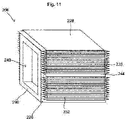
- Figure 11 illustrates an example of an elevator car enclosure 206 in accordance with another example of the present disclosure.
- the elevator car enclosure 206 is similar to the elevator car enclosure 106 described above, except that it is capable of expanding and contracting in a vertical plane.
- the elevator car enclosure 206 comprises a plurality of side walls 226, a ceiling 228 and a floor 230. In this example, all of the side walls 226 comprise corrugated portions 232, including the front and rear side walls 226.
- the elevator car enclosure 206 is capable of expanding and contracting in a vertical plane, i.e. in a vertical direction.
- the elevator car enclosure comprises a door-shaped opening 240 and a mounting feature 244 which may mount a support frame.
- Figure 12 shows a side view of the elevator car enclosure 206 in a contracted configuration.
- the corrugations 232 are compressed.
- Support members in the form of straps 248, e.g. ratchet straps, may hold the elevator car enclosure in the contracted configuration.
- the straps 248 may be released to allow expansion of the elevator car enclosure from the contracted configuration into an expanded configuration.
- Figure 13 shows a side view of the elevator car enclosure 206 in an expanded configuration.
- the elevator car enclosure 206 in this expanded configuration, in which the elevator car enclosure 206 has been expanded in the vertical plane, the elevator car enclosure 206 is held in the expanded configuration by support members 238.
- the weight of the elevator car enclosure 206 may tend to pull it back towards its contracted configuration, it may only be necessary to prevent the elevator car enclosure 206 from contracting, and it may not be necessary to stop it from expanding as this may be resisted by gravity.
- the locking members 246 are attached to the support members 238 on an underside 229 of the ceiling 228 of the elevator car enclosure 246.
- the locking members 246 thereby bare against the underside 229 of the ceiling 228 and together with the support members 238 prevent the elevator car enclosure 206 from contracting, i.e. collapsing.
- the support members 238 extend into the floor 230 and are secured in place by locking members 246.
- the support members 238 may, for example, extend into apertures in the floor 230.
- the weight of the elevator car enclosure 106 bearing down on the support members 238 from the ceiling 228 may be sufficient to hold the support members 238 in place in the floor 230 and the locking members 246 provided at the floor 230 may be omitted.
- Figures 14A and 14B illustrate an elevator car 304 which comprises an elevator car enclosure 306 and a cantilever support frame 334.
- the elevator car enclosure 306 is the same as the elevator car enclosure 106 described above.
- Figure 14A shows the elevator car 304 in a disassembled state and more clearly shows how the cantilever support frame 334 comprises a plurality of cantilever floor support members 334A.
- the cantilever floor support members 334A act to support an underside, i.e. the floor, of the elevator car enclosure 306.
- Figure 14B shows the elevator car in an assembled state with the elevator car enclosure 306 mounted to the cantilever support frame 334, and with the door assembly 324 attached to the elevator car enclosure 306.
- the elevator car 304 comprising a cantilever support frame 334 may be particularly well suited for use in elevator hoistways which only have a single wall to which the elevator car 304 can be mounted.
- the elevator car comprises a single elevator car enclosure
- the elevator car may comprise a plurality of elevator car enclosures which may be connected together in a modular manner.
- Figure 15A illustrates a view of another example of an elevator car 404 in a disassembled state.
- the elevator car 404 comprises a first elevator car enclosure 406A and a second elevator car enclosure 406B.
- the second elevator car enclosure 406B is the same as the elevator car enclosure 106 described above
- the first elevator car enclosure 406A is the same as the elevator car enclosure 106 described above, except that it has an additional opening at its rear.
- the support frame 434 comprises support members 434A, which extend to both sides of a central frame 434B, so as to be capable of supporting each of the first and second elevator car enclosures 406A, 406B.
- the first elevator car enclosure 406A comprises a forward opening 440A at its forward end and a rearward opening at its rearward end (not visible in this Figure).
- the second elevator car enclosure 406B comprises a single opening 440B. When assembled, the rearward opening on the rearward end of the first elevator car enclosure 406A is coupled to the opening 440B on the second elevator car enclosure 406B and thus allows a load to pass between each of the first and second elevator car enclosures 406A, 406B.
- the forward opening 440A on the first elevator car enclosure is closed by a door assembly 424.
- FIG 15B shows the elevator car 404 in a fully assembled state.
- the first and second elevator car enclosures 406A, 406B are mounted to the support frame 434 and the door assembly 424 is mounted to the first elevator car enclosure 406A to selectively close the forward opening 440A (not visible in this Figure).
- a single suspension element 410 is provided to raise and lower the elevator car 404.
- the suspension element 410 may comprise any number of suitable tension members, e.g. ropes, cables or steel belts.
- the volume of each of the first and second elevator car enclosures 406A, 406B couple together to form a single, combined, larger volume.
- the elevator car 404 thus has an increased volume and may be capable of carrying an increased load.
- the elevator car 404 may be capable of carrying an increased load, e.g. an increased number of objects and/or carrying larger or heavier objects.
- FIG 16 shows another example of an elevator car 504 comprising a first elevator car enclosure 506A and a second elevator car enclosure 506B supported by a support frame 534.
- the first and second elevator car enclosures 506A, 506B may be coupled together by any suitable means.
- the elevator car 504 comprises a first suspension element 410A and a second suspension element 410B.
- the first and second suspension elements 410A, 410B may allow the elevator car 504 to transport heavier loads.
- each of the elevator car enclosures may be coupled together to form a larger overall elevator car enclosure.
- Each of the elevator car enclosures may have any number of suitable openings which allow the passage of a load from one elevator car enclosure to an adjacent elevator car enclosure, as well as openings which allow a load to pass from an elevator car enclosure to another part of the elevator system, e.g. a landing thereof.
- the elevator car enclosures may be capable of expansion and contraction in both horizontal and vertical planes.
- the elevator car enclosure may comprise corrugations that facilitate such expansion.
- corrugations may be provided on all of the walls of the elevator car enclosure, as well as on the ceiling and floor thereof.
- the examples described above include a floor and a ceiling, this is not essential and the elevator car enclosure may, for example, be devoid of a ceiling.
- examples of the present disclosure provide an improved elevator car enclosure which is formed from a single moulded body, as well as an elevator car comprising such an elevator car enclosure. While specific examples of the disclosure have been described in detail, it will be appreciated by those skilled in the art that the examples described in detail are not limiting on the scope of the disclosure.
Abstract
Description
- This disclosure relates to an elevator car enclosure and a method of assembling an elevator car.
- Elevator cars often comprise a metal support frame to which a number of sheet metal panels are attached. The sheet metal panels typically define an enclosure in which passengers or goods may be transported. Such elevator cars are suitable for many applications; however, they are relatively expensive to produce and often relatively heavy due to the materials from which they are made. As a result, such elevator cars typically require specialised equipment to transport and install the elevator cars. Additionally, due to the materials from which the elevator cars are made, the elevator cars are relatively expensive to manufacture. Further, assembly of the elevator cars, which often occurs on site, can be time consuming.
- It would be advantageous to provide a means which addresses or mitigates at least some of the problems outlined above.
- In accordance with a first aspect, the present disclosure provides an elevator car enclosure which defines a volume for receiving a load to be transported, wherein the elevator car enclosure is formed from a single moulded body.
- Accordingly, as will be appreciated, forming the elevator car enclosure from a single moulded body may reduce the cost of manufacture of the elevator car enclosure when compared to prior art enclosures which are defined by multiple panels of sheet metal. Additionally, manufacture of the elevator car may be simplified when compared to prior art techniques as it may be easier to produce an elevator car enclosure from a single moulded body. Further, the overall assembly and installation time for an elevator car assembly may be reduced as the single moulded body of the elevator car enclosure may reduce the amount of on-site assembly which is required. The load to be transported may comprise passenger(s) and/or goods and/or any other object which may need to be transported.
- The single moulded body may comprise any suitable material that can be moulded to define the elevator car enclosure. In a set of examples, the single moulded body comprises a polymeric material. In other words, the single moulded body is made from a polymeric material. The polymeric material may be any suitable material. For example, the polymeric material may comprise plastic, e.g. high density polyethylene (HDPE). The polymeric material may also comprise at least one of: polyamide, polyvinylchloride, high-impact polystyrene, polycarbonate, polyester and polypropylene. The use of a polymeric material may advantageously minimise the mass of the elevator car enclosure, at least when compared to prior art enclosures which are formed from metal panels. This may mean that the elevator car enclosure is easier to transport and also easier to manoeuvre at an elevator installation site. This may advantageously minimise the number of personnel and/or specialist installation equipment required to install the elevator car enclosure. The single moulded body may be moulded by any suitable technique. For example, the single moulded body may be blow moulded and/or injection moulded.
- The single moulded body may also comprise other materials in addition to the polymeric material. For example, other materials may be embedded within the polymeric material. The single moulded body may, for example, comprise other materials which improve the structural rigidity of the elevator car enclosure. As such, the single moulded body may comprise integrally formed structural elements. For example, the single moulded body may comprise a plurality of reinforcing fibres arranged to reinforce at least portions of the single moulded body. The reinforcing fibres may comprise glass fibres, Kevlar fibres, carbon fibres or any other suitable material. The integrally formed structural elements may be positioned in specific portions of the single moulded body where reinforcement is required, e.g. on a floor thereof. Other materials may, for example, include fire prevention additives which are flame resistant and thus act to inhibit fire transmission within the elevator car enclosure.
- Elevator cars are typically relatively large, and thus the elevator car enclosure may thus define a relatively large volume. In a set of examples, the elevator car enclosure has a variable volume. The ability to vary, i.e. adjust, the volume of the elevator car enclosure may advantageously mean that the volume of the elevator car enclosure can be minimised for transportation of the elevator car enclosure to an elevator installation site, and subsequently be expanded once on site. This may mean that the elevator car enclosure can be transported to an installation site, and manoeuvred on site, more easily. Further, the ability to change the volume of the elevator car enclosure may advantageously mean that the volume, i.e. the size, of the elevator car enclosure can be adapted to suit a particular elevator installation. For example, the volume may be increased for an elevator installation which is designed to incorporate a larger elevator car. Accordingly, the ability to vary the volume of the elevator car enclosure may mean that a single elevator car enclosure can be manufactured which is suitable for a number of different elevator installations. This may minimise the tooling costs required to manufacture elevator car enclosures suitable for a plurality of different elevator installations.
- In a further set of examples, the elevator car enclosure is configured to be capable of expanding from a contracted configuration, in which the elevator car enclosure defines a first volume, into an expanded configuration in which the elevator car enclosure defines a second, larger volume. As will be appreciated, the elevator car enclosure may be transported and manoeuvred in the contracted configuration, and only expanded into the expanded configuration once at an elevator installation site. Of course, the elevator car enclosure may also be contracted from the expanded configuration into the contracted configuration. The elevator car enclosure may be capable of expanding into at least one further expanded configuration. As such, the size of the elevator car enclosure may be expanded to suit a size of the elevator installation in which it is installed.
- The variable volume of the elevator car enclosure, including the ability to expand and contract, may be achieved via any suitable means. For example, walls of the elevator car enclosure may facilitate expansion and contraction of the elevator car enclosure. In a set of examples, the elevator car enclosure comprises a plurality of walls which define the volume and wherein at least one of the plurality of walls comprises a corrugated structure configured to allow the elevator car enclosure to expand from the contracted configuration into the expanded configuration. A corrugated structure may provide a simple and convenient means to facilitate changing the volume of the elevator car enclosure. The corrugated structure may have any suitable form that permits expansion and/or contraction of the elevator car enclosure. The corrugated structure may, for example, have a waved or castellated structure. The corrugated structure may comprise a series of folds which define a plurality of ridges and grooves. In examples wherein multiple of the plurality of walls comprise a corrugated structure, the corrugated structure may effectively define a bellowed structure. The plurality of walls may include side walls of the elevator car enclosure, as well as the walls which define the ceiling and floor if included.
- In a set of examples, the elevator car enclosure is configured to be capable of expanding in a horizontal plane and/or a vertical plane. The ability to expand in a horizontal plane may allow the elevator car enclosure to be expanded to suit the dimensions of a particular elevator installation. Expansion in a horizontal plane may increase a floor space of the elevator car enclosure. A single elevator car enclosure may thus be suitable for a range of different sized elevator installations. Additionally, the ability to expand the elevator car enclosure in the horizontal plane may make assembly of the elevator car, which comprises the elevator car enclosure, easier as the elevator car enclosure can quickly and easily be adjusted to the desired shape and size. In a similar manner, the ability to expand in the vertical plane may advantageously mean that a height of the elevator car enclosure can be adjusted to a desired dimension.
- An elevator car enclosure which is configured to be capable of expanding in both the horizontal and vertical planes may mean that in a contracted configuration the elevator car enclosure occupies a minimum possible space. As with earlier examples, this may make transportation and manoeuvring of the elevator car enclosure easier. The ability to expand in both the vertical and horizontal direction may also provide the maximum degree of variability in the volume of the elevator car enclosure, and thus the elevator car enclosure may be suitable for a larger range of different elevator installations.
- When in the contracted configuration, the elevator car enclosure may tend to expand towards the expanded configuration. This may, for example, be due to an inherent resilient bias provided in the material of the single moulded body. For example, it may be due to a resilient bias provided by corrugations which permit the expansion of the elevator car enclosure. Expansion of the elevator car enclosure prior to installation at an elevator installation site may not be desirable. Thus, in a set of examples, the elevator car enclosure further comprises at least one support member arranged to hold the elevator car enclosure in the contracted configuration. The support member may be separate from the single moulded body, and thus be provided by a separate part. The support member may act to hold the elevator car enclosure in the contracted configuration until expansion of the elevator car enclosure is required. This may advantageously mean that the elevator car enclosure can be transported to, and manoeuvred at, an elevator installation site more easily. When the elevator car enclosure is on site and ready for installation, the at least one support member may be removed, or released, and the elevator car enclosure may be expanded into the expanded configuration. However, as will be appreciated, it may not always be necessary to hold the elevator car enclosure in the contracted configuration. For example, in examples wherein the elevator car enclosure is configured to expand in a vertical direction, the weight of the elevator car enclosure itself may be sufficient to hold the elevator car enclosure in the contracted configuration.
- When in the expanded configuration, the elevator car enclosure may be stable, i.e. it may remain in the expanded configuration, and thus there may not be any need to hold the elevator car enclosure in the expanded configuration. However, in some examples, the elevator car enclosure may tend to contract towards the contracted configuration. This may, for example, be due to gravity or other forces acting on the elevator car enclosure. Thus, in a set of examples, the elevator enclosure further comprises at least one support member arranged to hold the elevator car enclosure in the expanded configuration. As with the support member discussed above, the at least one support member may be a separate part to the single moulded body. The at least one support member may hold the elevator car enclosure in the expanded configuration and prevent it from moving towards the contracted configuration. This may help to ensure that in use the elevator car enclosure has fixed dimensions and does not collapse. The at least one support member may be the same support member as the support member discussed above for holding the elevator car enclosure in the contracted configuration or it may comprise a further support member.
- The at least one support member of either of the examples described above may be any support member that is capable of holding the elevator car enclosure in the respective configurations. For example, the at least one support member may comprise an at least partially threaded rod which engages with a corresponding threaded nut, or other suitable locking member. The at least partially threaded rod may be inserted through the elevator car enclosure and the threaded nuts may be secured in an appropriate manner to hold the elevator car enclosure in the respective configurations.
- As discussed above, the elevator car enclosure may be easier to install when compared to prior art elevator cars. In a further set of examples, the single moulded body comprises at least one integrally formed mounting feature for mounting an elevator car component to the elevator car enclosure. Integrally moulding a mounting feature of this type, i.e. forming the mounting feature from the same single moulded body, may further simplify manufacture of the elevator car enclosure as well as assembly of an elevator car comprising the elevator car enclosure. As will be appreciated, elevator car components may quickly and easily be mounted to the at least one integrally formed mounting feature and thus the assembly of the elevator car may be simplified. Integrally forming mounting features in this manner may also help to ensure that the elevator car components are mounted at the proper positions in the elevator car enclosure.
- The at least one integrally formed mounting feature may be suitable for mounting any suitable elevator car component. For example, the at least one integrally formed mounting feature may comprise a support frame mounting feature for mounting a support frame to the elevator car enclosure. In addition or alternatively, the at least one integrally formed mounting feature may comprise an integrally formed conduit for mounting at least one electrical cable within the elevator car enclosure. Further, the at least one integrally formed mounting feature may comprise a car operation panel mounting feature for mounting a car operation panel in the elevator car enclosure. For example, the car operation panel mounting feature may comprise a recessed portion in a wall of the elevator car enclosure.
- In examples comprising support members as discussed above, the elevator car enclosure may comprise integrally formed mounting features for the support members. For example, the elevator car enclosure may comprise integrally formed aperture(s) through which the at least one support member may extend.
- Elevator cars typically comprise a door assembly which controls access to the volume within the elevator car. In another set of examples, the single moulded body comprises an opening for allowing the passage of a load into the volume defined by the single moulded body. The opening may, for example, be door-shaped. Integrally forming the opening within the single moulded body may, similarly to the integrally formed mounting features discussed above, further simplify the assembly of an elevator car comprising the elevator car enclosure. For example, with the opening already present in the elevator car enclosure, an installer may simply install an elevator car door to the opening and door functionality may be provided. Including an opening in this manner may also ensure that the opening has the precise dimensions required and is thus capable of receiving the elevator car door. In some examples, the single moulded body may comprise a further opening so that the elevator car enclosure can allow ingress and egress through multiple openings. The opening and further opening may be on opposing sides of the elevator car enclosure.
- The elevator car enclosure may have any shape that defines a volume suitable for transporting a load. The shape of the elevator car enclosure may at least partially depend on the shape required for a particular elevator installation. In a set of examples, the single moulded body comprises a plurality of side walls which at least partially define the volume of the elevator car enclosure. For example, the plurality of side walls may comprise four walls arranged to at least partially define a cuboid-shaped volume. In embodiments comprising an opening, the opening may be present in one of the plurality of side walls.
- In another set of examples, the single moulded body comprises a floor and/or a ceiling which at least partially define the volume of the elevator car enclosure. Accordingly, the side walls, floor and ceiling may together define the volume of the elevator car enclosure.
- The elevator car enclosure may be capable of supporting a load such as passengers and/or goods which are to be transported by an elevator car. In some examples, the elevator car enclosure may be capable of supporting a load which comprises a plurality of objects, e.g. a plurality of passengers. The elevator car enclosure may be capable of supporting any suitable load. In a set of examples, the single moulded body is capable of supporting a mass of up to 1000 kg, e.g. up to 750 kg, e.g. up to 650 kg. The elevator car enclosure may thus be capable of supporting a plurality of passengers and/or a variety of different goods. Advantageously, this may mean that the elevator car enclosure is suitable for a variety of different elevator installations.
- In some examples, a first portion of single moulded body may have a first thickness, and a second portion may have a second, different thickness. For example, the floor, i.e. a first portion, of the elevator car enclosure may be thicker than the side walls, i.e. a second portion, of the elevator car enclosure. The increased thickness of the floor, at least compared to the side walls, may ensure that that the floor is capable of supporting a load thereon, whilst having the side walls thinner may help to minimise the weight of the elevator car enclosure. The relative thicknesses of the elevator car enclosure may be integrally formed as part of the moulding of the elevator car enclosure.
- According to another aspect of the present disclosure there is provided an elevator car comprising:
- one or more of the elevator car enclosures according to any of the examples described above; and
- a support frame configured to support the one or more elevator car enclosures.
- The support frame may be any frame that is capable of supporting the elevator car. For example, the support frame may comprise a cantilever support frame.
- In a further set of examples, the elevator car comprises at least two elevator car enclosures. Such an elevator car may be considered to have a modular construction with each of the elevator car enclosures being a module. Each of the elevator car enclosures may comprise a respective opening which is aligned with an opening in an adjacent elevator car enclosure so as to allow a load to pass through from one elevator car enclosure to the next. When provided together, the volume of each of the at least two elevator car enclosures may together provide a single, combined, larger volume. An elevator car comprising at least two elevator car enclosures arranged in this manner may be capable of transporting a load having a greater size and/or weight.
- In examples comprising at least two elevator car enclosures, each of the elevator car enclosures may be coupled to the other elevator car enclosures by any suitable arrangement. For example, the support frame may act to hold the elevator car enclosures together in a coupled manner. In another set of examples, there may be a coupling arrangement which acts to couple each of the elevator car enclosures to an adjacent elevator car enclosure. For example, each of the plurality of elevator car enclosures may be bolted together.
- In another set of examples, at least one of the one or more elevator car enclosures comprises an opening and the elevator car comprises a door arranged to selectively close the opening.
- As will be appreciated by those skilled in the art, assembly and installation of the elevator car including an elevator car enclosure described above will be quite different to the installation of prior art elevator cars. Therefore, according to a further aspect of the present disclosure there is provided a method of assembling an elevator car comprising a support frame and an elevator car enclosure which defines a volume and which is formed from a single moulded body, wherein the method comprises attaching the support frame to the elevator car enclosure to form the elevator car.
- The elevator car enclosure may comprise any of the features of the elevator car enclosure described above with reference to the first aspect of the present disclosure. In a set of examples, the elevator car enclosure has a variable volume and wherein the method comprises changing the volume of the elevator car enclosure to a desired volume at an elevator installation site.
- The elevator car enclosure may, for example, be expanded from a contracted configuration into an expanded configuration prior to attaching the support frame to the elevator car enclosure.
- In another set of examples, the elevator car enclosure comprises at least one integrally formed mounting feature, and wherein the method further comprises mounting an elevator car component to the at least one integrally formed mounting feature.
- In another set of examples, the elevator car enclosure comprises at least one support member configured to hold the elevator car enclosure in a contracted configuration and wherein the method further comprises removing or releasing the at least one support member to allow the elevator car enclosure to be expanded into an expanded configuration.
- In another set of examples, the elevator car enclosure comprises at least one support member configured to hold the elevator car enclosure in an expanded configuration and wherein the method further comprises configuring the at least one support member to hold the elevator car enclosure in an expanded configuration.
- In another set of examples, the elevator car enclosure comprises at least one opening to allow a load to pass into the volume, and wherein the method comprises securing a door assembly to the opening.
- In another set of examples, the method comprises attaching at least one further elevator car enclosure to the support frame. The at least one further elevator car enclosure may comprise any of the features of the elevator car enclosure according to examples of the first aspect of the present disclosure described above. Any of the steps described above with respect to the elevator car enclosure may also be performed on the further elevator car enclosure. In a further set of examples, the method comprises aligning an opening on the elevator car enclosure with an opening on the further elevator car enclosure.
- Certain examples of the present disclosure will now be described with reference to the accompanying drawings, in which:
-
Fig. 1 is a schematic illustration of an elevator system comprising an elevator car enclosure in accordance with an example of the present disclosure; -
Fig. 2 is a perspective view of the elevator car enclosure shown inFig. 1 in an expanded configuration; -
Fig. 3 is a perspective view of the elevator car enclosure shown inFig. 1 in a contracted configuration; -
Fig. 4 is a side view of the elevator car enclosure shown inFig. 1 in a contracted configuration; -
Fig. 5 is a side view of the elevator car enclosure shown inFig. 1 in an expanded configuration; -
Fig. 6 is an internal view of the elevator car enclosure shown inFig. 1 illustrating a car operating panel mounting feature; -
Fig. 7 is a view illustrating assembly of the elevator car shown inFig. 1 ; -
Fig. 8 is a perspective view of the fully assembled elevator car; -
Fig. 9 is a side view of the fully assembled elevator car shown inFig. 8 ; -
Fig. 10 is a front view of the elevator car shown inFig. 8 with the elevator car doors removed; -
Fig. 11 is a perspective view of another elevator car enclosure in accordance with another example of the present disclosure; -
Fig. 12 is a side view of the elevator car enclosure shown inFig. 11 in a contracted configuration; -
Fig. 13 is a side view of the elevator car enclosure shown inFig. 11 in an expanded configuration; -
Figs. 14A-14B are perspective views illustrating the mounting of an elevator car enclosure on a cantilever support frame; -
Fig. 15A-15B show perspective views illustrating an elevator car in accordance with an example of the present disclosure which comprises two elevator car enclosures; and -
Fig. 16 shows a perspective view of an elevator car which comprises two elevator car enclosures and two separate suspension elements. -
FIG. 1 is a perspective view of anelevator system 102 including anelevator car 104 which comprises anelevator car enclosure 106 in accordance with an example of the present disclosure. Theelevator system 102 further comprises acounterweight 108, asuspension element 110, aguide rail 112, anelevator machine 114, anencoder 116, and acontroller 118. Theelevator car 104 andcounterweight 108 are connected to each other by thesuspension element 110. Thesuspension element 110 may include or be configured as, for example, ropes, steel cables, and/or coated-steel belts. Thecounterweight 108 is configured to balance a load of theelevator car 104 and is configured to facilitate movement of theelevator car 104 concurrently and in an opposite direction with respect to thecounterweight 108 within anelevator shaft 120 and along theguide rail 112. - The
suspension element 108 engages theelevator machine 114, which is part of an overhead structure of theelevator system 102. Theelevator machine 114 is configured to control movement between theelevator car 104 and thecounterweight 108, and thus control the position of theelevator car 104 within theelevator shaft 120. Theencoder 116 may be mounted on afixed part 122 at the top of theelevator shaft 120, such as on a support or guide rail, and may be configured to provide position signals related to a position of theelevator car 104 within theelevator shaft 120. In other embodiments, theencoder 116 may be directly mounted to a moving component of theelevator machine 114, or may be located in other positions and/or configurations as known in the art. Theencoder 116 can be any device or mechanism for monitoring a position of an elevator car and/or counterweight, as known in the art. - The
controller 118 is configured to control the operation of theelevator system 102, and particularly theelevator car 104. For example, thecontroller 118 may provide drive signals to theelevator machine 114 to control the acceleration, deceleration, levelling, stopping, etc. of theelevator car 104. Thecontroller 118 may also be configured to receive position signals from theencoder 116 or any other desired position reference device. When moving up or down within theelevator shaft 120 alongguide rail 112, theelevator car 104 may stop at one or more landings as controlled by thecontroller 118. Thecontroller 118 may be located and/or configured in any suitable location or position within the elevator system 101. In one embodiment, thecontroller 118 may be located remotely or in the cloud. - The
elevator machine 114 may include a motor or similar driving mechanism. Theelevator machine 114 may be configured to include an electrically driven motor. The power supply for the motor may be any power source, including a power grid, which, in combination with other components, is supplied to the motor. Theelevator machine 114 may include a traction sheave that imparts force tosuspension element 110 to move theelevator car 104 withinelevator shaft 120. - The
elevator car 104 comprises anelevator car enclosure 106 which defines a volume (not visible in this Figure) therein for receiving a load to be transported. The load may comprise any object suitable for transportation by an elevator car. For example, the object may comprise a human, an animal, and/or goods. The elevator car enclosure comprises an opening which is door-shaped (not visible in this Figure) which is closed by anelevator car door 124. Theelevator car door 124 may comprise an automatic car door configured to be opened and closed when at respective landings in theelevator shaft 120. - The
elevator car enclosure 106 is formed from single moulded body. Theelevator car enclosure 106 may be formed from any suitable material, for example a polymeric material, e.g. plastic. Theelevator car enclosure 106 comprises a plurality ofside walls 126, aceiling 128 and afloor 130, all of which are integrally formed as a single body. In the example shown inFigure 1 , theside walls 126,ceiling 128 andfloor 130 all comprise corrugatedportions 132 which allow theelevator car enclosure 106 to expand into the expanded configuration as illustrated inFigure 1 . Accordingly, as will be appreciated, as a result of the ability to expand provided by thecorrugated portions 132, theelevator car enclosure 106 has a variable volume. - The
corrugated portions 132 may be integrally formed as part of a moulding process. Thecorrugated portions 132 may have any suitable form that permits expansion and contraction of theelevator car enclosure 106. For example, thecorrugated portions 132 need not necessarily comprise sharp ridges and grooves, as depicted inFigure 1 , and instead the corrugated portions may have a curved profile. - The
elevator car enclosure 106 is supported by asupport frame 134. As illustrated, thesupport frame 134 supports thefloor 130 of theelevator car enclosure 106 and also passes around theside walls 126 and over theceiling 128. Mounting of thesupport frame 134 may be facilitated by mounting features (not visible in this Figure) which are integrally provided with theelevator car enclosure 106. Thesupport frame 134 comprises a plurality ofguide shoes 136 which engage with theguide rail 112 and act to guide theelevator car 104 within theelevator shaft 120. - The
elevator car enclosure 106 further comprises a plurality ofsupport members 138, in the form of rods, which are arranged to hold theelevator car enclosure 106 in the expanded configuration shown inFigure 1 . As theelevator car enclosure 106 shown inFigure 1 is capable of expanding and contracting in the horizontal plane, the plurality of support members extend in a horizontal direction. -
Figure 2 shows a perspective view of theelevator car enclosure 106 in isolation from other parts of theelevator system 102. Theelevator car enclosure 106, including theside walls 126,ceiling 128 andfloor 130 is formed from a single moulded body. Thecorrugated portions 132 are also integrally formed as part of the single moulded body. As is visible in this Figure, theelevator car enclosure 106 comprises a door shaped opening 140 for allowing the passage of a load into, and out of, thevolume 142 defined by theelevator car enclosure 106. - The
elevator car enclosure 106 comprises a supportframe mounting feature 144 arranged between the twocorrugated portions 132. The supportframe mounting feature 144 is dimensioned to mount thesupport frame 134 shown inFigure 1 , and ensures the proper positioning of thesupport frame 134 on theelevator car enclosure 106. - In
Figure 2 , theelevator car enclosure 106 is shown in its expanded configuration.Figure 3 illustrates theelevator car enclosure 106 in its contracted configuration. As will be appreciated by those skilled in the art, due to the arrangement of thecorrugated portions 132, theelevator car enclosure 106 is able to expand and contract in the horizontal plane. The ability to expand and contract in this manner may advantageously make transport of theelevator car enclosure 106 to an installation site easier. In the contracted state, theelevator car enclosure 106 will take up less space and will thus require less space to transport. This may allow moreelevator car enclosures 106 to be transported, or reduce the size of the vehicle required to transport theelevator car enclosure 106. Additionally, moving theelevator car enclosure 106 into position on site may also be easier in the contracted configuration shown inFigure 3 . Further, as discussed above, the ability to expand theelevator car enclosure 106 may allow theelevator car enclosure 106 to be expanded to the desired size on site. Theelevator car enclosure 106 may thus be expanded to meet the size requirements of the particular elevator installation where it is being installed. -
Figure 4 shows a side view of theelevator car enclosure 106 in the contracted configuration. As depicted in this Figure, thecorrugated portions 132 are compressed so that theelevator car enclosure 106 is in the contracted configuration. As theelevator car enclosure 106 may be manufactured from an at least partially resilient material, e.g. plastic, when in the compressed state shown in this Figure, thecorrugated portions 132 tend to try to expand and thereby act to expand theelevator car enclosure 106 into an expanded configuration. As depicted, thesupport members 138 may act to hold theelevator car enclosure 106 in the contracted position. Thesupport member 138 may pass throughend portions 144 of theelevator car enclosure 106 and engage with lockingmembers 146. The lockingmembers 146 may, for example, comprise internally threaded nuts which engage with an external thread provided at least on the ends of each of thesupport members 138. As will be appreciated by those skilled in the art, thesupport members 138 and the lockingmembers 146 may be capable of securing theelevator car enclosure 106 in the contracted configuration. - In addition or alternatively to the
support members 138 and lockingmembers 146, straps 148, e.g. in the form of ratchet straps, may be provided to secure theelevator car enclosure 106 in the contracted configuration. Thestraps 148 may be removed when it is desired to expand the elevator car enclosure into the expanded configuration. -
Figure 5 shows a side view of theelevator car enclosure 106 in the expanded configuration. This expanded configuration may be achieved by releasing the lockingmembers 146 shown inFigure 4 , thus allowing thecorrugated portions 132 to expand thus expanding the elevator car enclosure into the expanded configuration. Thesupport member 138 shown inFigure 4 may be extendable and thus may also act to support theelevator car enclosure 106 in the expanded configuration. Of course, a further, different support member may be used to support the elevator car enclosure in the expanded configuration. In the expanded configuration, lockingmembers 146 may be secured to anoutside face 147 of theend portions 144 and further lockingmembers 150 may be secured to thesupport member 138 on aninside face 149 of theend portions 144. As will be appreciated, this arrangement may prevent theelevator car enclosure 106 from expanding or contracting. -
Figure 6 shows a cutaway view of theelevator car enclosure 106. As depicted, theelevator car enclosure 106 comprises an integrally moulded car operatingpanel mounting feature 152 which is defined by a recess in theside wall 126. Additionally, theelevator car enclosure 106 comprises an integrally mouldedconduit 154 for mounting at least one cable in theelevator car enclosure 106. For example, theconduit 154 may be for mounting a cable which is connected to a car operating panel mounted within the car operatingpanel mounting feature 152. Of course, theelevator car enclosure 106 may comprise any number of different mounting features. For example, theelevator car enclosure 106 may comprise mounting features for mounting lights, speakers, handrails or any other element within the elevator car. - Assembly of the
elevator car 104 shown inFigure 1 will now be described with reference toFigure 7 . Theelevator car enclosure 106 may be transported to a site and expanded from its contracted configuration into an expanded configuration in a size suitable for the particular elevator installation. This may be achieved, for example, by operators removing the lockingmembers 146 orstraps 148 shown inFigure 4 . Theelevator car enclosure 106 may then expand automatically under the resilience provided by thecorrugated portions 132. In addition or alternatively, installers may physically pull theelevator car enclosure 106 into the expanded state. - The
elevator car enclosure 106 may then be inserted into thesupport frame 134. As can be seen inFigure 7 , thesupport frame 134 comprises a plurality offloor support members 134A as well as wall andceiling support member 134B. Theelevator car enclosure 106 may be flexible, e.g. due to the material from which it is made from and thecorrugated portions 132, and thus it may be possible to push the elevator car enclosure into theopening 156 defined by theframe 134 so that the wall andceiling support member 134B is mounted within the supportframe mounting feature 144. Theelevator car enclosure 106 may flex and change shape slightly as it is inserted into theframe 134. Of course, at least part of thesupport frame 134 may be disassembled and subsequently reassembled around theelevator car enclosure 106. Thesupport members 138 may also be secured in place so as to hold theelevator car enclosure 106 in its expanded position. This may be performed before, or after, the elevator car enclosure has been inserted into thesupport frame 134. - The
elevator car door 124 may be mounted to theelevator car enclosure 106 before, or after, thesupport frame 134 has been mounted to theelevator car enclosure 106. -
Figure 8 shows theelevator car 104 in the fully assembled state, i.e. with thesupport frame 134 and theelevator car door 124 mounted to theelevator car enclosure 106 which is in the expanded configuration.Figure 9 shows a side-on view of theelevator car 104 in the fully assembled state. As depicted, thesupport members 138, together with the lockingmembers 146 and further lockingmembers 150 hold theelevator car enclosure 106 in the expanded configuration even when thesupport frame 134 is attached thereto. Whilst not shown, thesupport frame 134 may also engage with theelevator car enclosure 106 in a manner which holds the elevator car enclosure in the expanded configuration. -
Figure 10 shows a front view of theelevator car 104, with theelevator car door 124 removed. As visible in this front view, theelevator car enclosure 106 comprisesframe mounting features 158 integrally formed in thefloor 132 of theelevator car enclosure 106. The frame mounting features 158 are shaped to receive thefloor support members 134A. The frame mounting features 158 may ensure the proper mounting of thefloor support members 134A, thus ensuring that thefloor 132 is properly supported by thefloor support members 134A. - The
elevator car enclosure 106 in the example described above is capable of expanding and contracting in the horizontal plane. The vertical dimension of theelevator car enclosure 106 is fixed and the horizontal dimension may be changed. However, in certain instances it may be desirable to be able to expand and/or contract the elevator car in the vertical direction.Figure 11 illustrates an example of anelevator car enclosure 206 in accordance with another example of the present disclosure. Theelevator car enclosure 206 is similar to theelevator car enclosure 106 described above, except that it is capable of expanding and contracting in a vertical plane. Theelevator car enclosure 206 comprises a plurality ofside walls 226, aceiling 228 and afloor 230. In this example, all of theside walls 226 comprise corrugatedportions 232, including the front andrear side walls 226. In this example, there are no corrugations on theceiling 228 or on thefloor 230 as these are not required in order to facilitate expansion in the vertical plane. As a result, theelevator car enclosure 206 is capable of expanding and contracting in a vertical plane, i.e. in a vertical direction. Similarly to the example described above, the elevator car enclosure comprises a door-shapedopening 240 and a mountingfeature 244 which may mount a support frame. -
Figure 12 shows a side view of theelevator car enclosure 206 in a contracted configuration. As depicted, in the contracted configuration thecorrugations 232 are compressed. Support members in the form ofstraps 248, e.g. ratchet straps, may hold the elevator car enclosure in the contracted configuration. Thestraps 248 may be released to allow expansion of the elevator car enclosure from the contracted configuration into an expanded configuration. -
Figure 13 shows a side view of theelevator car enclosure 206 in an expanded configuration. As depicted, in this expanded configuration, in which theelevator car enclosure 206 has been expanded in the vertical plane, theelevator car enclosure 206 is held in the expanded configuration bysupport members 238. As the weight of theelevator car enclosure 206 may tend to pull it back towards its contracted configuration, it may only be necessary to prevent theelevator car enclosure 206 from contracting, and it may not be necessary to stop it from expanding as this may be resisted by gravity. In this regard, as depicted, the lockingmembers 246 are attached to thesupport members 238 on anunderside 229 of theceiling 228 of theelevator car enclosure 246. The lockingmembers 246 thereby bare against theunderside 229 of theceiling 228 and together with thesupport members 238 prevent theelevator car enclosure 206 from contracting, i.e. collapsing. As shown, thesupport members 238 extend into thefloor 230 and are secured in place by lockingmembers 246. Thesupport members 238 may, for example, extend into apertures in thefloor 230. As will be appreciated, the weight of theelevator car enclosure 106 bearing down on thesupport members 238 from theceiling 228 may be sufficient to hold thesupport members 238 in place in thefloor 230 and the lockingmembers 246 provided at thefloor 230 may be omitted. -
Figures 14A and 14B illustrate anelevator car 304 which comprises anelevator car enclosure 306 and acantilever support frame 334. Theelevator car enclosure 306 is the same as theelevator car enclosure 106 described above.Figure 14A shows theelevator car 304 in a disassembled state and more clearly shows how thecantilever support frame 334 comprises a plurality of cantileverfloor support members 334A. As will be appreciated, when theelevator car enclosure 306 is mounted to the frame, the cantileverfloor support members 334A act to support an underside, i.e. the floor, of theelevator car enclosure 306.Figure 14B shows the elevator car in an assembled state with theelevator car enclosure 306 mounted to thecantilever support frame 334, and with thedoor assembly 324 attached to theelevator car enclosure 306. Theelevator car 304 comprising acantilever support frame 334 may be particularly well suited for use in elevator hoistways which only have a single wall to which theelevator car 304 can be mounted. - Whilst in the various examples described above, the elevator car comprises a single elevator car enclosure, the elevator car may comprise a plurality of elevator car enclosures which may be connected together in a modular manner.
Figure 15A illustrates a view of another example of anelevator car 404 in a disassembled state. As shown, theelevator car 404 comprises a firstelevator car enclosure 406A and a secondelevator car enclosure 406B. The secondelevator car enclosure 406B is the same as theelevator car enclosure 106 described above, and the firstelevator car enclosure 406A is the same as theelevator car enclosure 106 described above, except that it has an additional opening at its rear. - The
support frame 434 comprisessupport members 434A, which extend to both sides of acentral frame 434B, so as to be capable of supporting each of the first and secondelevator car enclosures elevator car enclosure 406A comprises aforward opening 440A at its forward end and a rearward opening at its rearward end (not visible in this Figure). The secondelevator car enclosure 406B comprises asingle opening 440B. When assembled, the rearward opening on the rearward end of the firstelevator car enclosure 406A is coupled to theopening 440B on the secondelevator car enclosure 406B and thus allows a load to pass between each of the first and secondelevator car enclosures forward opening 440A on the first elevator car enclosure is closed by adoor assembly 424. -
Figure 15B shows theelevator car 404 in a fully assembled state. As shown, the first and secondelevator car enclosures support frame 434 and thedoor assembly 424 is mounted to the firstelevator car enclosure 406A to selectively close theforward opening 440A (not visible in this Figure). In the example shown inFigure 15B , asingle suspension element 410 is provided to raise and lower theelevator car 404. Thesuspension element 410 may comprise any number of suitable tension members, e.g. ropes, cables or steel belts. The volume of each of the first and secondelevator car enclosures elevator car 404 thus has an increased volume and may be capable of carrying an increased load. Theelevator car 404 may be capable of carrying an increased load, e.g. an increased number of objects and/or carrying larger or heavier objects. - In some examples, particularly in those where the elevator car comprises multiple elevator car enclosures, the elevator car may be capable of transporting a heavier load. Accordingly, it may be necessary to provide additional suspension elements to support the weight of the elevator car and any load therein.
Figure 16 shows another example of anelevator car 504 comprising a firstelevator car enclosure 506A and a secondelevator car enclosure 506B supported by asupport frame 534. The first and secondelevator car enclosures Figure 16 , theelevator car 504 comprises afirst suspension element 410A and asecond suspension element 410B. The first andsecond suspension elements elevator car 504 to transport heavier loads. - It will be appreciated that any number of elevator car enclosures may be coupled together to form a larger overall elevator car enclosure. Each of the elevator car enclosures may have any number of suitable openings which allow the passage of a load from one elevator car enclosure to an adjacent elevator car enclosure, as well as openings which allow a load to pass from an elevator car enclosure to another part of the elevator system, e.g. a landing thereof.
- Whilst not depicted in the examples above, the elevator car enclosures may be capable of expansion and contraction in both horizontal and vertical planes. In this regard, the elevator car enclosure may comprise corrugations that facilitate such expansion. For example, corrugations may be provided on all of the walls of the elevator car enclosure, as well as on the ceiling and floor thereof. Further, whilst the examples described above include a floor and a ceiling, this is not essential and the elevator car enclosure may, for example, be devoid of a ceiling.
- Accordingly, it will be appreciated by those skilled in the art that examples of the present disclosure provide an improved elevator car enclosure which is formed from a single moulded body, as well as an elevator car comprising such an elevator car enclosure. While specific examples of the disclosure have been described in detail, it will be appreciated by those skilled in the art that the examples described in detail are not limiting on the scope of the disclosure.
Claims (15)
- An elevator car enclosure (106, 206, 306, 406A; 406B, 506A; 506B) which defines a volume (142) for receiving a load to be transported, wherein the elevator car enclosure (106, 206, 306, 406A; 406B, 506A; 506B) is formed from a single moulded body.
- The elevator car enclosure (106, 206, 306, 406A; 406B, 506A; 506B) as claimed in claim 1, wherein the single moulded body comprises a polymeric material.
- The elevator car enclosure (106, 206, 306, 406A; 406B, 506A; 506B) as claimed in any preceding claim, wherein the elevator car enclosure (106, 206, 306, 406A; 406B, 506A; 506B) has a variable volume (142).
- The elevator car enclosure (106, 206, 306, 406A; 406B, 506A; 506B) as claimed in claim 3, configured to be capable of expanding from a contracted configuration, in which the elevator car enclosure (106, 206, 306, 406A; 406B, 506A; 506B) has a first volume, into an expanded configuration in which the elevator car enclosure (106, 206, 306, 406A; 406B, 506A; 506B) has a second, larger volume.
- The elevator car enclosure (106, 206, 306, 406A; 406B, 506A; 506B) as claimed in claim 4, comprising a plurality of walls (126; 128; 130, 226; 228; 230) which define the volume (142) and wherein at least one of the plurality of walls (126; 128; 130, 226; 228; 230) comprise a corrugated structure (132, 232) configured to allow the elevator car enclosure (106, 206, 306, 406A; 406B, 506A; 506B) to expand from the contracted configuration into the expanded configuration.
- The elevator car enclosure (106, 206, 306, 406A; 406B, 506A; 506B) as claimed in claim 4 or 5, wherein the elevator car enclosure (106, 206, 306, 406A; 406B, 506A; 506B) is configured to be capable of expanding in a horizontal plane and/or a vertical plane.
- The elevator car (106, 206, 306, 406A; 406B, 506A; 506B) enclosure as claimed in one of claims 4-6, further comprising at least one support member (138; 148, 248) arranged to hold the elevator car enclosure in the contracted configuration.
- The elevator car enclosure (106, 206, 306, 406A; 406B, 506A; 506B) as claimed in any preceding claim, further comprising at least one support member (138, 238) arranged to hold the elevator car enclosure (106, 206, 306, 406A; 406B, 506A; 506B) in the expanded configuration.
- The elevator car enclosure (106, 206, 306, 406A; 406B, 506A; 506B) as claimed in any preceding claim, wherein the single moulded body comprises at least one integrally formed mounting feature (144; 152; 154; 158, 244) for mounting an elevator car component to the elevator car enclosure (106, 206, 306, 406A; 406B, 506A; 506B).
- The elevator car enclosure (106, 206, 306, 406A; 406B, 506A; 506B) as claimed in any preceding claim, wherein the single moulded body comprises an opening (140, 240) for allowing the passage of a load into the volume (142) defined by the single moulded body.
- The elevator car enclosure (106, 206, 306, 406A; 406B, 506A; 506B) as claimed in any preceding claim, wherein the single moulded body comprises a plurality of side walls (126, 226) which at least partially define the volume (142) of the elevator car enclosure (106, 206, 306, 406A; 406B, 506A; 506B).
- The elevator car enclosure (106, 206, 306, 406A; 406B, 506A; 506B) as claimed in any preceding claim, wherein the single moulded body comprises a floor (130, 230) and/or a ceiling (128, 228) which at least partially define the volume (142) of the elevator car enclosure (106, 206, 306, 406A; 406B, 506A; 506B).
- An elevator car comprising:one or more of the elevator car enclosures according to any one of claims 1 to 12; anda frame configured to support the one or more elevator car enclosures.
- A method of assembling an elevator car (104, 304, 404, 504, 604) comprising a support frame (134, 334, 434, 534, 634) and an elevator car enclosure (106, 206, 306, 406A; 406B, 506A; 506B) which defines a volume (142) and which is formed from a single moulded body, wherein the method comprises attaching the support frame (134, 334, 434, 534, 634) to the elevator car enclosure (106, 206, 306, 406A; 406B, 506A; 506B) to form the elevator car (104, 304, 404, 504, 604).
- The method as claimed in claim 14, wherein the elevator car enclosure (106 206, 306, 406A; 406B, 506A; 506B) has a variable volume (142) and wherein the method comprises changing the volume (142) of the elevator car enclosure (106 206, 306, 406A; 406B, 506A; 506B) to a desired volume at an elevator installation site.
Priority Applications (3)
| Application Number | Priority Date | Filing Date | Title |
|---|---|---|---|
| EP20383050.0A EP4008672A1 (en) | 2020-12-03 | 2020-12-03 | Elevator car enclosure with variable volume formed from a single moulded body |
| US17/401,936 US20220177275A1 (en) | 2020-12-03 | 2021-08-13 | Elevator car enclosure |
| CN202110948388.8A CN114604715A (en) | 2020-12-03 | 2021-08-18 | Elevator car shell |
Applications Claiming Priority (1)
| Application Number | Priority Date | Filing Date | Title |
|---|---|---|---|
| EP20383050.0A EP4008672A1 (en) | 2020-12-03 | 2020-12-03 | Elevator car enclosure with variable volume formed from a single moulded body |
Publications (1)
| Publication Number | Publication Date |
|---|---|
| EP4008672A1 true EP4008672A1 (en) | 2022-06-08 |
Family
ID=73834410
Family Applications (1)
| Application Number | Title | Priority Date | Filing Date |
|---|---|---|---|
| EP20383050.0A Pending EP4008672A1 (en) | 2020-12-03 | 2020-12-03 | Elevator car enclosure with variable volume formed from a single moulded body |
Country Status (3)
| Country | Link |
|---|---|
| US (1) | US20220177275A1 (en) |
| EP (1) | EP4008672A1 (en) |
| CN (1) | CN114604715A (en) |
Citations (4)
| Publication number | Priority date | Publication date | Assignee | Title |
|---|---|---|---|---|
| JPS51142254U (en) * | 1975-05-10 | 1976-11-16 | ||
| JP2005289596A (en) * | 2004-04-01 | 2005-10-20 | Mitsubishi Electric Corp | Elevator device and elevator car |
| CN106429753A (en) * | 2016-12-16 | 2017-02-22 | 重庆迈高电梯有限公司 | Elevator car with car top space extensible |
| WO2017127005A1 (en) * | 2016-01-18 | 2017-07-27 | Articulated Funiculator Ab | Elevator cabin assembly and method of producing an elevator cabin assembly |
Family Cites Families (16)
| Publication number | Priority date | Publication date | Assignee | Title |
|---|---|---|---|---|
| US4361208A (en) * | 1980-12-22 | 1982-11-30 | Westinghouse Electric Corp. | Modular elevator car |
| US5207295A (en) * | 1991-10-01 | 1993-05-04 | Otis Elevator Company | Lightweight prefabricated elevator cab |
| JPH06278973A (en) * | 1993-03-30 | 1994-10-04 | Mitsubishi Electric Corp | Cage ceiling device for elevator |
| JP2008037548A (en) * | 2006-08-03 | 2008-02-21 | Mitsubishi Electric Corp | Car of elevator |
| FI20106044A (en) * | 2010-10-11 | 2012-04-12 | Kone Corp | Elevator |
| CN203612779U (en) * | 2013-12-18 | 2014-05-28 | 黄立成 | Elevator device with driving component having functions of signal transmission and traction driving |
| DE202014001106U1 (en) * | 2014-02-06 | 2014-02-20 | Geda-Dechentreiter Gmbh & Co. Kg | Car for a lift |
| WO2017072255A1 (en) * | 2015-10-30 | 2017-05-04 | Inventio Ag | Maintenance platform for an elevator cab |
| SE539383C2 (en) * | 2016-01-18 | 2017-09-05 | Articulated Funiculator Ab | Elevator cabin assembly |
| WO2018011460A1 (en) * | 2016-07-15 | 2018-01-18 | Kone Corporation | Elevator arrangement |
| WO2018011461A1 (en) * | 2016-07-15 | 2018-01-18 | Kone Corporation | Elevator arrangement with low headroom |
| CN109476458B (en) * | 2016-07-15 | 2021-03-09 | 通力股份公司 | Elevator device for opening the roof of an elevator car |
| WO2018011457A1 (en) * | 2016-07-15 | 2018-01-18 | Kone Corporation | Elevator arrangement and elevator |
| CN106904515B (en) * | 2017-04-28 | 2023-07-18 | 重庆迈高电梯有限公司 | Elevator car capable of expanding car top space |
| CN110884982A (en) * | 2019-12-06 | 2020-03-17 | 福建快科城建增设电梯股份有限公司 | Volume-increasing and speed-increasing stretcher elevator and working method thereof |
| EP3909897A1 (en) * | 2020-05-12 | 2021-11-17 | KONE Corporation | Elevator car, elevator and method |
-
2020
- 2020-12-03 EP EP20383050.0A patent/EP4008672A1/en active Pending
-
2021
- 2021-08-13 US US17/401,936 patent/US20220177275A1/en not_active Abandoned
- 2021-08-18 CN CN202110948388.8A patent/CN114604715A/en active Pending
Patent Citations (4)
| Publication number | Priority date | Publication date | Assignee | Title |
|---|---|---|---|---|
| JPS51142254U (en) * | 1975-05-10 | 1976-11-16 | ||
| JP2005289596A (en) * | 2004-04-01 | 2005-10-20 | Mitsubishi Electric Corp | Elevator device and elevator car |
| WO2017127005A1 (en) * | 2016-01-18 | 2017-07-27 | Articulated Funiculator Ab | Elevator cabin assembly and method of producing an elevator cabin assembly |
| CN106429753A (en) * | 2016-12-16 | 2017-02-22 | 重庆迈高电梯有限公司 | Elevator car with car top space extensible |
Also Published As
| Publication number | Publication date |
|---|---|
| US20220177275A1 (en) | 2022-06-09 |
| CN114604715A (en) | 2022-06-10 |
Similar Documents
| Publication | Publication Date | Title |
|---|---|---|
| US20170247121A1 (en) | Unknown | |
| US10589964B2 (en) | Elevator car, elevator system and method of checking, maintaining and/or repairing an elevator system | |
| US11713574B2 (en) | Cross-struts for beam assemblies | |
| JP6827746B2 (en) | Systems and methods for transporting passengers, flight attendants, containers and serving carts | |
| KR890000741B1 (en) | Modular elevator car | |
| US20200199894A1 (en) | Platform positioning system, method of operating a platform positioning system, and wind turbine | |
| US11780706B2 (en) | Modular elevator assembly and rail | |
| AU2018319105B2 (en) | Elevator system | |
| US5207295A (en) | Lightweight prefabricated elevator cab | |
| EP0985624B1 (en) | Elevator with drive unit supported by guide rail | |
| US20200277164A1 (en) | Working platform for an elevator car | |
| EP4008672A1 (en) | Elevator car enclosure with variable volume formed from a single moulded body | |
| JP6227153B2 (en) | Ceiling unit and elevator car with ceiling unit | |
| US20230249797A1 (en) | Aircraft fuselage and module for absorbing crash energy in a lower deck, used for transporting passengers, of an aircraft | |
| KR101216428B1 (en) | elevator system and installation method | |
| EP2796399B1 (en) | A platform assembly and a method for manufacturing an elevator car | |
| EP3725730B1 (en) | A crane comprising a movable boom and a movable counterweight | |
| US10981754B2 (en) | Elevator car wall | |
| US10138097B2 (en) | Hoist assembly and method of lifting | |
| US5394923A (en) | Resilient barrier gate | |
| EP3418241B1 (en) | An elevator car | |
| JP4035202B2 (en) | elevator | |
| US5199530A (en) | Retainer assembly | |
| ITMI941205A1 (en) | SELF-SUPPORTING LIFT, LIFT OR SIMILAR DEVICE | |
| JPH10101279A (en) | Elevator car device |
Legal Events
| Date | Code | Title | Description |
|---|---|---|---|
| PUAI | Public reference made under article 153(3) epc to a published international application that has entered the european phase |
Free format text: ORIGINAL CODE: 0009012 |
|
| STAA | Information on the status of an ep patent application or granted ep patent |
Free format text: STATUS: THE APPLICATION HAS BEEN PUBLISHED |
|
| AK | Designated contracting states |
Kind code of ref document: A1 Designated state(s): AL AT BE BG CH CY CZ DE DK EE ES FI FR GB GR HR HU IE IS IT LI LT LU LV MC MK MT NL NO PL PT RO RS SE SI SK SM TR |
|
| STAA | Information on the status of an ep patent application or granted ep patent |
Free format text: STATUS: REQUEST FOR EXAMINATION WAS MADE |
|
| 17P | Request for examination filed |
Effective date: 20221118 |
|
| RBV | Designated contracting states (corrected) |
Designated state(s): AL AT BE BG CH CY CZ DE DK EE ES FI FR GB GR HR HU IE IS IT LI LT LU LV MC MK MT NL NO PL PT RO RS SE SI SK SM TR |