EP4008520A1 - Single-screw screw extruder for plastification - Google Patents
Single-screw screw extruder for plastification Download PDFInfo
- Publication number
- EP4008520A1 EP4008520A1 EP21209758.8A EP21209758A EP4008520A1 EP 4008520 A1 EP4008520 A1 EP 4008520A1 EP 21209758 A EP21209758 A EP 21209758A EP 4008520 A1 EP4008520 A1 EP 4008520A1
- Authority
- EP
- European Patent Office
- Prior art keywords
- screw
- groove
- helical
- cylinder
- cooling
- Prior art date
- Legal status (The legal status is an assumption and is not a legal conclusion. Google has not performed a legal analysis and makes no representation as to the accuracy of the status listed.)
- Withdrawn
Links
Images


Classifications
-
- B—PERFORMING OPERATIONS; TRANSPORTING
- B29—WORKING OF PLASTICS; WORKING OF SUBSTANCES IN A PLASTIC STATE IN GENERAL
- B29C—SHAPING OR JOINING OF PLASTICS; SHAPING OF MATERIAL IN A PLASTIC STATE, NOT OTHERWISE PROVIDED FOR; AFTER-TREATMENT OF THE SHAPED PRODUCTS, e.g. REPAIRING
- B29C48/00—Extrusion moulding, i.e. expressing the moulding material through a die or nozzle which imparts the desired form; Apparatus therefor
- B29C48/25—Component parts, details or accessories; Auxiliary operations
- B29C48/36—Means for plasticising or homogenising the moulding material or forcing it through the nozzle or die
- B29C48/50—Details of extruders
- B29C48/68—Barrels or cylinders
- B29C48/6801—Barrels or cylinders characterised by the material or their manufacturing process
-
- B—PERFORMING OPERATIONS; TRANSPORTING
- B29—WORKING OF PLASTICS; WORKING OF SUBSTANCES IN A PLASTIC STATE IN GENERAL
- B29C—SHAPING OR JOINING OF PLASTICS; SHAPING OF MATERIAL IN A PLASTIC STATE, NOT OTHERWISE PROVIDED FOR; AFTER-TREATMENT OF THE SHAPED PRODUCTS, e.g. REPAIRING
- B29C48/00—Extrusion moulding, i.e. expressing the moulding material through a die or nozzle which imparts the desired form; Apparatus therefor
- B29C48/25—Component parts, details or accessories; Auxiliary operations
- B29C48/36—Means for plasticising or homogenising the moulding material or forcing it through the nozzle or die
- B29C48/50—Details of extruders
- B29C48/68—Barrels or cylinders
- B29C48/685—Barrels or cylinders characterised by their inner surfaces, e.g. having grooves, projections or threads
- B29C48/686—Barrels or cylinders characterised by their inner surfaces, e.g. having grooves, projections or threads having grooves or cavities
-
- B—PERFORMING OPERATIONS; TRANSPORTING
- B29—WORKING OF PLASTICS; WORKING OF SUBSTANCES IN A PLASTIC STATE IN GENERAL
- B29C—SHAPING OR JOINING OF PLASTICS; SHAPING OF MATERIAL IN A PLASTIC STATE, NOT OTHERWISE PROVIDED FOR; AFTER-TREATMENT OF THE SHAPED PRODUCTS, e.g. REPAIRING
- B29C48/00—Extrusion moulding, i.e. expressing the moulding material through a die or nozzle which imparts the desired form; Apparatus therefor
- B29C48/25—Component parts, details or accessories; Auxiliary operations
- B29C48/78—Thermal treatment of the extrusion moulding material or of preformed parts or layers, e.g. by heating or cooling
- B29C48/80—Thermal treatment of the extrusion moulding material or of preformed parts or layers, e.g. by heating or cooling at the plasticising zone, e.g. by heating cylinders
- B29C48/83—Heating or cooling the cylinders
- B29C48/834—Cooling
Definitions
- the invention relates to a single-screw extruder for plasticizing plastics, with an in particular one-piece cylinder and with a conveyor screw that can be rotated in a cylinder chamber of the cylinder, with the cylinder chamber being assigned a feed zone, a plasticizing zone positioned behind the feed zone in the conveying direction, and a cooling zone downstream of the plasticizing zone, which are controlled by a cooling device is surrounded.
- a single-screw extruder is from the DE 10 2017 207 357 A1 known.
- the well-known single-screw extruder has a one-piece cylinder and a screw conveyor rotatably mounted in a cylinder space of the cylinder.
- the cylinder chamber is provided with a feed area and a transition zone that tapers conically in the conveying direction and then with a plasticizing zone.
- the feed area and the transition zone of the cylinder chamber are provided with helical grooves.
- a further embodiment shows a continuation of the helical grooves into the plasticizing zone.
- a single-screw extruder for the production of mozzarella which has a multi-part cylinder and a screw conveyor rotatably mounted in the cylinder.
- Heating or cooling means are assigned to an outer casing of the cylinder, with a cylinder wall being provided with a ribbed structure on the outside in the region of the heating or cooling means.
- the object of the invention is to provide a single-screw extruder of the type mentioned at the outset which is suitable for producing foamed plastics.
- the cylinder is provided on the inside in the area of the cooling zone with at least one helical groove open towards the screw conveyor, and in that the cylinder is provided on the outside in the area of the cooling zone with at least one cooling groove which is assigned to the helical groove in such a way that a wall thickness of the cylinder that is reduced compared to a cylinder wall thickness results between the inside helical groove and the outside cooling groove.
- the at least one cooling groove is assigned to the at least one helical groove in such a way that wall sections of the cylinder form heat transfer bridges between these inner and outer grooves, which ensure rapid cooling of the plastic melt in the cylinder space by the cooling device surrounding the cooling zone.
- At least one helical groove open to the screw conveyor is provided, which extends over the entire length of the cooling zone - in the axial direction of the screw conveyor seen.
- a plurality of helical grooves can be provided which are aligned parallel to one another and each extend over only a partial area of the axial length of the cooling zone. Up to forty such helical grooves are advantageously provided.
- the solution according to the invention is particularly advantageous for the physical foaming of plastics with gases such as nitrogen or CO 2 in particular. A corresponding gas is injected into the completely melted plastic melt. After the gas injection, the gas within the plastic melt must be homogenized, with the aim preferably being to completely dissolve the gas in the plastic melt.
- the dissolved gas reduces the viscosity of the gas-laden plastic melt.
- the at least one helical groove in the cooling zone increases the surface area of the wall of the cylinder space for a corresponding heat transfer.
- a cooling liquid flows through the cooling grooves during operation of the single-screw extruder.
- a gas injection point is assigned to the cylinder space upstream of the cooling zone in the conveying direction.
- the gas injection point is preferably provided at the end of a plasticizing zone, so that appropriate gas can be injected at a point at which the plastic material is completely melted.
- the at least one cooling groove has a helical design.
- the at least one helical groove and the at least one cooling groove have the same helical pitch and are arranged alternately with respect to one another in an axially offset manner relative to a central longitudinal axis of the cylinder chamber.
- the concept of the same spiral pitches also means that the spirals rotate in the same direction.
- Axially offset is to be understood as meaning an axial offset relative to a central longitudinal axis of the cylinder space.
- the alternating shifting relative to each other means that an outside cooling groove and an inside spiral groove are always positioned evenly offset from one another, so that the walls of the at least one spiral groove have a constant wall thickness of the cylinder on both sides.
- the helical groove and the cooling groove superimpose one another in sections radially to an axis of rotation of the screw conveyor. This refinement further improves heat transfer between the at least one cooling groove and the at least one helical groove.
- the cooling device has a cooling jacket in the form of an annular collar, which encloses the cooling zone of the cylinder in a circumferentially supporting manner.
- the cooling jacket helps to achieve sufficient pressure resistance for the thin-walled design of the cylinder in the area of the cooling zone.
- the all-round support provided by the annular sleeve-shaped cooling jacket increases the pressure resistance of the cylinder in the area of this cooling zone.
- the conveyor screw is designed as a wave screw with a helically corrugated screw core on which at least one helical screw web is applied, which defines at least one screw thread that has alternating thread depths due to the helical corrugation of the screw core.
- the shaft worm thus forms a worm helix with respect to its at least one worm thread. It is essential that the corrugation crests of the screw helix, i.e. the screw flight, are in the direction of the screw flight and not in the axial direction of the screw conveyor.
- this shaft screw creates areas in each axial position of the cooling zone of the cylinder with each revolution of the shaft screw around the entire circumference in which the plastic melt has a lot of space between the shaft screw and the wall of the cylinder chamber, and other areas in which only very there is little space between the auger and the wall of the cylinder chamber.
- high and low flight depths alternate.
- the low screw flight depths are necessary in order to generate a high shear rate for the plastic melt in the helical grooves. This enables the plastic melt to be conveyed well through the helical grooves and reliably prevents the plastic melt from stagnating in the helical grooves.
- a helical direction of the helical screw flight is designed in the opposite direction to a helical direction of the at least one helical groove of the cylinder chamber in the region of the cooling zone. This configuration improves homogenization of the gas-laden plastic melt.
- the at least one helical groove has a groove pitch from a range of 0.5 to 50 times, preferably 0.5 to 5 times, an inner diameter of the cylinder chamber. This configuration has proven particularly advantageous for achieving a functioning foaming process for the gas-loaded plastic melt.
- a groove length of the helical groove corresponds to at least three times the inside diameter of the cylinder chamber and less than 25 times that Inner diameter of the cylinder space. This range is advantageous for the production of a homogeneous plastic foam material.
- the helical groove is provided with an inlet area with a groove depth that increases from zero in the conveying direction, with a constant area with a constant groove depth and with an outlet area with a groove depth that reduces to zero.
- the inlet and outlet areas ensure that no melt material can become lodged in the at least one helical groove.
- the inlet area and the outlet area each have an axial length in a range from 0.3 to 1 times the inner diameter of the cylinder chamber.
- a pitch of the at least one screw thread corresponds to between 0.5 and 10 times the inner diameter of the cylinder space.
- a width of the at least one screw flight preferably corresponds to 0.1 to 0.2 times the inner diameter of the cylinder space.
- the alternating flight depth of the screw flight is advantageously between 0.05 and 40 mm, depending on a diameter of the shaft screw.
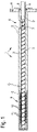
- a single-screw extruder 1 after Figures 1 to 3 is intended for the production of foamed plastic material.
- the single-screw extruder 1 has a one-piece cylinder 2 which is held stationary in a holder H at one end.
- a cylinder space 8 is provided in the cylinder 2, which extends over the entire length of the cylinder 2, so that the cylinder 2 forms a hollow cylinder.
- a screw conveyor 3 can be rotated in the cylinder space 8 stored, based on the 1 and 2 is shown only schematically.
- the screw conveyor 3 forms a shaft screw described in more detail below. In the cross-sectional view according to 3 this shaft snail is shown in its actual geometric configuration.
- the screw conveyor 3 extends over the entire length of the cylinder space 8.
- the screw conveyor 3 serves to transport pourable plastic material, preferably in the form of plastic granules, fed through a filling opening 7 to a feed zone 4 of the cylinder 2, away from the feed zone 4 in the direction of an in 1 and 2 promote outlet of the cylinder chamber 8 shown on the left.
- the cylinder 2 is assigned a heating device, not shown in detail, through which the plastic material is melted and converted into a completely plasticized plastic melt.
- the screw conveyor 3 is provided with a drive extension 6 at a front end region opposite the outlet, which is rotatably mounted in a bearing block 5 of the cylinder 2 .
- a drive system is assigned to the drive extension 6 in a manner not shown in detail, which drives the conveyor screw 3 in a direction of rotation that enables the plastic material to be conveyed away from the feed zone 4 in the direction of the outlet of the cylinder chamber 8 .
- a gas injection point G is provided, in which gas is supplied to the cylinder chamber 8, which gas is provided for foaming the plastic melt.
- the single-screw extruder 1 has a cooling zone 9, which 2 is shown enlarged.
- the cooling zone 9 is provided in the area of the cylinder chamber 8 with helical grooves 12 open towards the center of the cylinder chamber, with a single, continuous helical groove 12 extending over a large number of coils over the length of the cooling zone 9 in the illustrated embodiment.
- the helical groove 12 has an inlet area at the beginning of the cooling zone 9, during which the depth of the helical groove 12 increases from zero to the maximum depth, which remains constant over a constant area and thus over almost the entire length of the cooling zone 9.
- an outlet area can be seen for the helical groove 12, in which the depth of the helical groove is reduced again to zero.
- the cylinder 2 has at least one helical cooling groove 11 which is open towards an outer circumference of the cylinder 2 .
- the various groove windings of the cooling groove 11 have the same spacing from one another as the helical groove windings of the helical groove 12.
- There is one alternating from the outside to the inside in the direction of an axis of rotation D of the screw conveyor 3 extended groove winding of the cooling groove 11 is combined with a helical groove 12 of the cylinder chamber 8 extending from the inside to the outside, the inner helical groove 12 and the outer cooling groove 11 overlapping one another radially to the axis of rotation D slightly.
- the cylinder 2 preferably has a low radial compressive strength due to the small wall thickness between the overlapping cooling grooves 11 and helical grooves 12 in the area of the cooling zone 9, the cylinder 2 is stepped radially inwards in the area of its outer circumference in the area of this cooling zone 9 and on the stepped An annular sleeve-shaped cooling jacket 10 is applied in the area.
- both the helical cooling groove 11 and the inner helical groove 12 each have the same helical pitch.
- a depth of the cooling groove 11 is greater than a depth of the constant region of the helical groove 12 by more than half.
- the cooling groove 11 and the helical groove 12 are open to opposite sides in the radial direction.
- the conveyor screw 3 designed as a shaft screw has a helical screw thread 3b at least over an axial length of the cooling zone 9, which is delimited by a screw web 3a running helically on the outer circumference of the screw core.
- the wavy worm gear formed in this way between the turns of the worm flight 3a thus forms crests and troughs in the direction of the worm gear and thus along a helical line, so that the worm gear 3b permanently transitions from a high thread depth to a low thread depth.
- the flight depth is the distance between the outer casing of the screw core and the inner wall of the cylinder space 8 .
- the depth of screw flight 3b thus changes with each revolution of screw conveyor 3.
Landscapes
- Engineering & Computer Science (AREA)
- Mechanical Engineering (AREA)
- Manufacturing & Machinery (AREA)
- Physics & Mathematics (AREA)
- Thermal Sciences (AREA)
- Extrusion Moulding Of Plastics Or The Like (AREA)
Abstract
Einschneckenextruder zur KunststoffplastifizierungDer Zylinder des Einschneckenextruders ist im Bereich der Kühlzone innenseitig mit wenigstens einer zu der Förderschnecke hin offenen Wendelnut versehen, und der Zylinder ist außenseitig im Bereich der Kühlzone mit wenigstens einer Kühlnut versehen, die der Wendelnut derart zugeordnet ist, dass sich zwischen der innenseitigen Wendelnut und der außenseitigen Kühlnut eine gegenüber einer Zylinderwandungsstärke reduzierte Wandungsstärke des Zylinders ergibt. Der Einschneckenextruder wird zur Herstellung von geschäumten Kunststoffen eingesetzt.Single-screw extruder for plasticizing The cylinder of the single-screw extruder is provided with at least one helical groove on the inside in the area of the cooling zone, which is open towards the conveyor screw, and the cylinder is provided with at least one cooling groove on the outside in the area of the cooling zone, which is assigned to the helical groove in such a way that between the inside Helical groove and the outside cooling groove results in a wall thickness of the cylinder that is reduced compared to a cylinder wall thickness. The single-screw extruder is used to produce foamed plastics.
Description
Die Erfindung betrifft einen Einschneckenextruder zur Kunststoffplastifizierung mit einem insbesondere einteiligen Zylinder und mit einer in einem Zylinderraum des Zylinders drehbaren Förderschnecke, wobei dem Zylinderraum eine Einzugszone, eine in Förderrichtung hinter der Einzugszone positionierte Plastifizierzone und eine der Plastifizierzone nachgelagerte Kühlzone zugeordnet sind, die von einer Kühleinrichtung umgeben ist.The invention relates to a single-screw extruder for plasticizing plastics, with an in particular one-piece cylinder and with a conveyor screw that can be rotated in a cylinder chamber of the cylinder, with the cylinder chamber being assigned a feed zone, a plasticizing zone positioned behind the feed zone in the conveying direction, and a cooling zone downstream of the plasticizing zone, which are controlled by a cooling device is surrounded.
Ein Einschneckenextruder ist aus der
Aus der
Aufgabe der Erfindung ist es, einen Einschneckenextruder der eingangs genannten Art zu schaffen, der zur Herstellung geschäumter Kunststoffe geeignet ist.The object of the invention is to provide a single-screw extruder of the type mentioned at the outset which is suitable for producing foamed plastics.
Diese Aufgabe wird dadurch gelöst, dass der Zylinder im Bereich der Kühlzone innenseitig mit wenigstens einer zu der Förderschnecke hin offenen Wendelnut versehen ist, und dass der Zylinder außenseitig im Bereich der Kühlzone mit wenigstens einer Kühlnut versehen ist, die der Wendelnut derart zugeordnet ist, dass sich zwischen der innenseitigen Wendelnut und der außenseitigen Kühlnut eine gegenüber einer Zylinderwandungsstärke reduzierte Wandungsstärke des Zylinders ergibt. Die wenigstens eine Kühlnut ist der wenigstens einen Wendelnut derart zugeordnet, dass Wandungsabschnitte des Zylinders zwischen diesen innen-und außenseitigen Nuten Wärmeübergangsbrücken bilden, durch die eine schnelle Abkühlung der Kunststoffschmelze im Zylinderraum durch die die Kühlzone umgebende Kühleinrichtung gewährleistet ist. Erfindungsgemäß ist wenigstens eine zur Förderschnecke hin offene Wendelnut vorgesehen, die sich über eine gesamte Länge der Kühlzone erstreckt - in axialer Richtung der Förderschnecke gesehen. In vorteilhafter Weise können mehrere Wendelnuten vorgesehen sein, die parallel zueinander ausgerichtet sind und sich jeweils nur über einen Teilbereich der axialen Länge der Kühlzone erstrecken. Vorteilhaft sind bis zu vierzig derartiger Wendelnuten vorgesehen. Die erfindungsgemäße Lösung ist besonders vorteilhaft für das physikalische Schäumen von Kunststoffen mit Gasen wie insbesondere Stickstoff oder CO2 vorgesehen. Dabei wird ein entsprechendes Gas in die vollständig aufgeschmolzene Kunststoffschmelze injiziert. Nach der Gasinjektion muss das Gas innerhalb der Kunststoffschmelze homogenisiert werden, wobei vorzugsweise ein vollständiges Lösen des Gases in der Kunststoffschmelze erzielt werden soll. Durch das gelöste Gas sinkt eine Viskosität der gasbeladenen Kunststoffschmelze ab. Um einen funktionierenden Schäumprozess zu gewährleisten, ist es notwendig, die Kunststoffschmelze herunterzukühlen. Durch die wenigstens eine Wendelnut in der Kühlzone wird eine Oberfläche der Wandung des Zylinderraums für einen entsprechenden Wärmeübergang vergrößert. Die außenseitigen Kühlnuten, die in ihrer Positionierung auf die innenseitigen Wendelnuten abgestimmt sind, ergeben gemeinsam mit diesen innenseitigen Wendelnuten eine Dünnwandigkeit des Zylinders, die eine Kühlleistung begünstigt. Die Kühlnuten sind im Betrieb des Einschneckenextruders von einer Kühlflüssigkeit durchströmt.This object is achieved in that the cylinder is provided on the inside in the area of the cooling zone with at least one helical groove open towards the screw conveyor, and in that the cylinder is provided on the outside in the area of the cooling zone with at least one cooling groove which is assigned to the helical groove in such a way that a wall thickness of the cylinder that is reduced compared to a cylinder wall thickness results between the inside helical groove and the outside cooling groove. The at least one cooling groove is assigned to the at least one helical groove in such a way that wall sections of the cylinder form heat transfer bridges between these inner and outer grooves, which ensure rapid cooling of the plastic melt in the cylinder space by the cooling device surrounding the cooling zone. According to the invention, at least one helical groove open to the screw conveyor is provided, which extends over the entire length of the cooling zone - in the axial direction of the screw conveyor seen. Advantageously, a plurality of helical grooves can be provided which are aligned parallel to one another and each extend over only a partial area of the axial length of the cooling zone. Up to forty such helical grooves are advantageously provided. The solution according to the invention is particularly advantageous for the physical foaming of plastics with gases such as nitrogen or CO 2 in particular. A corresponding gas is injected into the completely melted plastic melt. After the gas injection, the gas within the plastic melt must be homogenized, with the aim preferably being to completely dissolve the gas in the plastic melt. The dissolved gas reduces the viscosity of the gas-laden plastic melt. In order to ensure a functioning foaming process, it is necessary to cool down the plastic melt. The at least one helical groove in the cooling zone increases the surface area of the wall of the cylinder space for a corresponding heat transfer. The cooling grooves on the outside, the positioning of which is matched to the helical grooves on the inside, result, together with these helical grooves on the inside, in a thin-walled cylinder that promotes cooling performance. A cooling liquid flows through the cooling grooves during operation of the single-screw extruder.
In Ausgestaltung der Erfindung ist dem Zylinderraum in Förderrichtung vor der Kühlzone eine Gasinjektionsstelle zugeordnet. Die Gasinjektionsstelle ist vorzugsweise endseitig einer Plastifizierzone vorgesehen, so dass entsprechendes Gas an einer Stelle injiziert werden kann, an der das Kunststoffmaterial vollständig aufgeschmolzen ist.In an embodiment of the invention, a gas injection point is assigned to the cylinder space upstream of the cooling zone in the conveying direction. The gas injection point is preferably provided at the end of a plasticizing zone, so that appropriate gas can be injected at a point at which the plastic material is completely melted.
In weiterer Ausgestaltung der Erfindung ist die wenigstens eine Kühlnut wendelförmig gestaltet. In vorteilhafter Weise weisen die wenigstens eine Wendelnut und die wenigstens eine Kühlnut gleiche Wendelsteigungen auf und sind auf eine Mittellängsachse des Zylinderraums bezogen axial versetzt alternierend zueinander angeordnet. Der Begriff der gleichen Wendelsteigungen bedeutet bei dieser Ausgestaltung auch einen gleichen Drehsinn der Wendelungen. Unter axial versetzt ist ein axiales Versetzen relativ zu einer Mittellängsachse des Zylinderraums zu verstehen. Das alternierende Versetzen relativ zueinander bedeutet, dass jeweils immer eine außenseitige Kühlnut und eine innenseitige Wendelnut gleichmäßig versetzt zueinander positioniert sind, so dass sich beidseitig der Wandungen der wenigstens einen Wendelnut jeweils eine gleichbleibende Wandungsstärke des Zylinders ergibt.In a further embodiment of the invention, the at least one cooling groove has a helical design. Advantageously, the at least one helical groove and the at least one cooling groove have the same helical pitch and are arranged alternately with respect to one another in an axially offset manner relative to a central longitudinal axis of the cylinder chamber. In this embodiment, the concept of the same spiral pitches also means that the spirals rotate in the same direction. Axially offset is to be understood as meaning an axial offset relative to a central longitudinal axis of the cylinder space. The alternating shifting relative to each other means that an outside cooling groove and an inside spiral groove are always positioned evenly offset from one another, so that the walls of the at least one spiral groove have a constant wall thickness of the cylinder on both sides.
In weiterer Ausgestaltung der Erfindung überlagern die Wendelnut und die Kühlnut einander radial zu einer Drehachse der Förderschnecke abschnittsweise. Diese Ausgestaltung verbessert einen Wärmeübergang zwischen der wenigstens einen Kühlnut und der wenigstens einen Wendelnut weiter.In a further embodiment of the invention, the helical groove and the cooling groove superimpose one another in sections radially to an axis of rotation of the screw conveyor. This refinement further improves heat transfer between the at least one cooling groove and the at least one helical groove.
In weiterer Ausgestaltung der Erfindung weist die Kühleinrichtung einen ringmanschettenförmigen Kühlmantel auf, der die Kühlzone des Zylinders umlaufend stützend umschließt. Der Kühlmantel trägt dazu bei, für die dünnwandige Gestaltung des Zylinders im Bereich der Kühlzone eine ausreichende Druckfestigkeit zu erzielen. Die umlaufende Stützung durch den ringmanschettenförmigen Kühlmantel erhöht die Druckfestigkeit des Zylinders im Bereich dieser Kühlzone.In a further embodiment of the invention, the cooling device has a cooling jacket in the form of an annular collar, which encloses the cooling zone of the cylinder in a circumferentially supporting manner. The cooling jacket helps to achieve sufficient pressure resistance for the thin-walled design of the cylinder in the area of the cooling zone. The all-round support provided by the annular sleeve-shaped cooling jacket increases the pressure resistance of the cylinder in the area of this cooling zone.
In weiterer Ausgestaltung der Erfindung ist die Förderschnecke als Wellenschnecke gestaltet mit einem wendelförmig gewellten Schneckenkern, auf dem wenigstens ein wendelförmiger Schneckensteg aufgebracht ist, der wenigstens einen Schneckengang definiert, der aufgrund der wendelförmigen Wellung des Schneckenkerns alternierende Gangtiefen aufweist. Die Wellenschnecke bildet somit bezüglich ihres wenigstens einen Schneckengangs eine Schneckenwendel. Maßgeblich ist es, dass entsprechende Wellenberge der Schneckenwendel, d.h. des Schneckengangs, in Schneckengangrichtung und nicht in Axialrichtung der Förderschnecke eingebracht sind. Im Betrieb des Einschneckenextruders entstehen durch diese Wellenschnecke an jeder axialen Position der Kühlzone des Zylinders mit jeder Umdrehung der Wellenschnecke am gesamten Umfang Bereiche, in denen die Kunststoffschmelze viel Platz zwischen der Wellenschnecke und der Wandung des Zylinderraums hat, und weitere Bereiche, in denen lediglich sehr wenig Platz zwischen der Förderschnecke und der Wandung des Zylinderraums ist. Somit wechseln hohe und niedrige Schneckengangtiefen einander ab. Die niedrigen Schneckengangtiefen sind notwendig, um in den Wendelnuten eine hohe Schergeschwindigkeit für die Kunststoffschmelze zu erzeugen. Dies ermöglicht eine gute Förderung der Kunststoffschmelze durch die Wendelnuten hindurch und verhindert zuverlässig eine Stagnation der Kunststoffschmelze in den Wendelnuten.In a further embodiment of the invention, the conveyor screw is designed as a wave screw with a helically corrugated screw core on which at least one helical screw web is applied, which defines at least one screw thread that has alternating thread depths due to the helical corrugation of the screw core. The shaft worm thus forms a worm helix with respect to its at least one worm thread. It is essential that the corrugation crests of the screw helix, i.e. the screw flight, are in the direction of the screw flight and not in the axial direction of the screw conveyor. During operation of the single-screw extruder, this shaft screw creates areas in each axial position of the cooling zone of the cylinder with each revolution of the shaft screw around the entire circumference in which the plastic melt has a lot of space between the shaft screw and the wall of the cylinder chamber, and other areas in which only very there is little space between the auger and the wall of the cylinder chamber. Thus, high and low flight depths alternate. The low screw flight depths are necessary in order to generate a high shear rate for the plastic melt in the helical grooves. This enables the plastic melt to be conveyed well through the helical grooves and reliably prevents the plastic melt from stagnating in the helical grooves.
In weiterer Ausgestaltung der Erfindung ist eine Wendelrichtung des wendelförmigen Schneckenstegs entgegengerichtet zu einer Wendelrichtung der wenigstens einen Wendelnut des Zylinderraums im Bereich der Kühlzone ausgeführt. Diese Ausgestaltung verbessert eine Homogenisierung der gasbeladenen Kunststoffschmelze.In a further embodiment of the invention, a helical direction of the helical screw flight is designed in the opposite direction to a helical direction of the at least one helical groove of the cylinder chamber in the region of the cooling zone. This configuration improves homogenization of the gas-laden plastic melt.
In weiterer Ausgestaltung der Erfindung weist die wenigstens eine Wendelnut eine Nutsteigung aus einem Bereich von 0,5- bis 50-mal, vorzugsweise 0,5- bis 5-mal, einem Innendurchmesser des Zylinderraums auf. Diese Ausgestaltung hat sich als besonders vorteilhaft erwiesen für die Erzielung eines funktionierenden Schäumprozesses für die gasbeladene Kunststoffschmelze.In a further embodiment of the invention, the at least one helical groove has a groove pitch from a range of 0.5 to 50 times, preferably 0.5 to 5 times, an inner diameter of the cylinder chamber. This configuration has proven particularly advantageous for achieving a functioning foaming process for the gas-loaded plastic melt.
In weiterer Ausgestaltung der Erfindung entspricht eine Nutlänge der Wendelnut wenigstens dem Dreifachen des Innendurchmessers des Zylinderraums und weniger als 25-mal dem Innendurchmesser des Zylinderraums. Dieser Bereich ist vorteilhaft für die Herstellung eines homogenen Kunststoffschaummaterials.In a further embodiment of the invention, a groove length of the helical groove corresponds to at least three times the inside diameter of the cylinder chamber and less than 25 times that Inner diameter of the cylinder space. This range is advantageous for the production of a homogeneous plastic foam material.
In weiterer Ausgestaltung der Erfindung ist die Wendelnut mit einem Einlaufbereich mit sich in Förderrichtung von Null aus vergrößernder Nuttiefe, mit einem Konstantbereich mit konstanter Nuttiefe und mit einem Auslaufbereich mit sich bis auf Null reduzierender Nuttiefe versehen. Der Einlauf- und der Auslaufbereich gewährleisten, dass sich kein Schmelzematerial in der wenigstens einen Wendelnut festsetzen kann. Vorteilhaft weisen der Einlaufbereich und der Auslaufbereich jeweils eine axiale Länge aus einem Bereich von 0,3- bis 1-mal dem Innendurchmesser des Zylinderraums auf.In a further embodiment of the invention, the helical groove is provided with an inlet area with a groove depth that increases from zero in the conveying direction, with a constant area with a constant groove depth and with an outlet area with a groove depth that reduces to zero. The inlet and outlet areas ensure that no melt material can become lodged in the at least one helical groove. Advantageously, the inlet area and the outlet area each have an axial length in a range from 0.3 to 1 times the inner diameter of the cylinder chamber.
In weiterer Ausgestaltung der Erfindung entspricht eine Gangsteigung des wenigstens einen Schneckengangs zwischen 0,5- und 10-mal dem Innendurchmesser des Zylinderraums. Zudem entspricht vorzugsweise eine Breite des wenigstens einen Schneckenstegs 0,1- bis 0,2-mal dem Innendurchmesser des Zylinderraums. Schließlich beträgt vorteilhaft die alternierende Gangtiefe des Schneckengangs zwischen 0,05 und 40 mm abhängig von einem Durchmesser der Wellenschnecke. Diese Ausgestaltungen tragen ebenfalls zur Erzielung einer Homogenisierung der gasbeladenen Kunststoffschmelze bei.In a further embodiment of the invention, a pitch of the at least one screw thread corresponds to between 0.5 and 10 times the inner diameter of the cylinder space. In addition, a width of the at least one screw flight preferably corresponds to 0.1 to 0.2 times the inner diameter of the cylinder space. Finally, the alternating flight depth of the screw flight is advantageously between 0.05 and 40 mm, depending on a diameter of the shaft screw. These configurations also contribute to achieving homogenization of the gas-laden plastic melt.
Weitere Vorteile und Merkmale der Erfindung ergeben sich aus den Ansprüchen sowie aus der nachfolgenden Beschreibung eines bevorzugten Ausführungsbeispiels der Erfindung, das anhand der Zeichnungen dargestellt ist.
- Fig. 1
- zeigt einen Längsschnitt durch eine bevorzugte Ausführungsform eines erfindungsgemäßen Einschneckenextruders,
- Fig. 2
- in vergrößerter Darstellung einen Ausschnitt des Längsschnitts gemäß
Fig. 1 im Bereich einer Kühlzone und - Fig. 3
- in vergrößerter Darstellung einen Querschnitt entlang der Schnittlinie III-III durch den Ausschnitt gemäß
Fig. 2 .
- 1
- shows a longitudinal section through a preferred embodiment of a single-screw extruder according to the invention,
- 2
- in an enlarged view according to a section of the longitudinal section
1 in the area of a cooling zone and - 3
- in an enlarged view a cross section along the section line III-III through the section according to FIG
2 .
Ein Einschneckenextruder 1 nach den
Endseitig der Plastifizierzone ist eine Gasinjektionsstelle G vorgesehen, in der dem Zylinderraum 8 Gas zugeführt wird, das zum Schäumen der Kunststoffschmelze vorgesehen ist. Im Anschluss an diese Gasinjektionsstelle G weist der Einschneckenextruder 1 eine Kühlzone 9 auf, die in
Wie anhand der
Alternierend zu den nach innen zum Zylinderraum 8 hin offenen Wendelnuten weist der Zylinder 2 wenigstens eine wendelförmige Kühlnut 11 auf, die zu einem Außenumfang des Zylinders 2 hin offen ist. Wie in
In
Die als Wellenschnecke gestaltete Förderschnecke 3 weist wenigstens über eine axiale Länge der Kühlzone 9 einen wendelförmig gestalteten Schneckengang 3b auf, der durch einen wendelförmig auf dem Außenumfang des Schneckenkerns verlaufenden Schneckensteg 3a begrenzt ist. Der so gebildete, wellenförmige Schneckengang zwischen den Windungen des Schneckenstegs 3a bildet somit in Schneckengangrichtung und damit entlang einer Wendellinie Wellenberge und Wellentäler, so dass der Schneckengang 3b permanent von einer hohen Gangtiefe in eine niedrige Gangtiefe übergeht. Unter der Gangtiefe ist der Abstand des Außenmantels des Schneckenkerns zur Innenwandung des Zylinderraums 8 zu verstehen. Der Schneckengang 3b verändert sich in seiner Tiefe somit bei jeder Umdrehung der Förderschnecke 3.The
Claims (15)
Applications Claiming Priority (1)
| Application Number | Priority Date | Filing Date | Title |
|---|---|---|---|
| DE102020215145.8A DE102020215145B4 (en) | 2020-12-01 | 2020-12-01 | Single-screw extruder for plastics plasticization |
Publications (1)
| Publication Number | Publication Date |
|---|---|
| EP4008520A1 true EP4008520A1 (en) | 2022-06-08 |
Family
ID=78770395
Family Applications (1)
| Application Number | Title | Priority Date | Filing Date |
|---|---|---|---|
| EP21209758.8A Withdrawn EP4008520A1 (en) | 2020-12-01 | 2021-11-23 | Single-screw screw extruder for plastification |
Country Status (2)
| Country | Link |
|---|---|
| EP (1) | EP4008520A1 (en) |
| DE (1) | DE102020215145B4 (en) |
Citations (7)
| Publication number | Priority date | Publication date | Assignee | Title |
|---|---|---|---|---|
| US2242364A (en) * | 1938-06-18 | 1941-05-20 | Montanari Cesare | Machine for manufacturing macaroni automatically |
| DE2936592A1 (en) * | 1979-09-11 | 1981-03-12 | Eberhard Dipl.-Ing. 7000 Stuttgart Grünschloß | Thermoplastics extruder free from excessive internal pressure - has defined screw lead angle along pre-plasticising middle zone |
| DE202010017570U1 (en) * | 2010-10-26 | 2012-03-21 | Entex Rust & Mitschke Gmbh | Extrusion plant for the production of highly filled plastics |
| DE102011086981A1 (en) | 2011-11-23 | 2013-05-23 | Helix GmbH | Single-screw extruder and method for producing a plasticized food product |
| WO2017050400A1 (en) * | 2015-09-27 | 2017-03-30 | Entex Rust & Mitschke Gmbh | Planetary roller extruder having a central screw coupling |
| DE102017207357A1 (en) | 2017-03-23 | 2018-09-27 | Helix GmbH | Single-screw extruder for plastics plasticization |
| DE102018001412A1 (en) * | 2017-12-11 | 2019-06-13 | Entex Rust & Mitschke Gmbh | Degassing during the extrusion of substances, preferably plastics |
Family Cites Families (4)
| Publication number | Priority date | Publication date | Assignee | Title |
|---|---|---|---|---|
| US2639464A (en) | 1950-01-03 | 1953-05-26 | Nat Rubber Machinery Co | Extrusion apparatus |
| NL146744B (en) | 1964-05-12 | 1975-08-15 | Shell Int Research | PROCESS FOR MANUFACTURING FOAM POLYSTYRENE FOILS. |
| JPS5985725A (en) | 1982-11-08 | 1984-05-17 | Mitsui Toatsu Chem Inc | Manufacturing device for thermoplastic resin foamed product |
| DE102012008023B4 (en) | 2012-04-21 | 2016-06-02 | Kraussmaffei Technologies Gmbh | screw extruder |
-
2020
- 2020-12-01 DE DE102020215145.8A patent/DE102020215145B4/en not_active Expired - Fee Related
-
2021
- 2021-11-23 EP EP21209758.8A patent/EP4008520A1/en not_active Withdrawn
Patent Citations (7)
| Publication number | Priority date | Publication date | Assignee | Title |
|---|---|---|---|---|
| US2242364A (en) * | 1938-06-18 | 1941-05-20 | Montanari Cesare | Machine for manufacturing macaroni automatically |
| DE2936592A1 (en) * | 1979-09-11 | 1981-03-12 | Eberhard Dipl.-Ing. 7000 Stuttgart Grünschloß | Thermoplastics extruder free from excessive internal pressure - has defined screw lead angle along pre-plasticising middle zone |
| DE202010017570U1 (en) * | 2010-10-26 | 2012-03-21 | Entex Rust & Mitschke Gmbh | Extrusion plant for the production of highly filled plastics |
| DE102011086981A1 (en) | 2011-11-23 | 2013-05-23 | Helix GmbH | Single-screw extruder and method for producing a plasticized food product |
| WO2017050400A1 (en) * | 2015-09-27 | 2017-03-30 | Entex Rust & Mitschke Gmbh | Planetary roller extruder having a central screw coupling |
| DE102017207357A1 (en) | 2017-03-23 | 2018-09-27 | Helix GmbH | Single-screw extruder for plastics plasticization |
| DE102018001412A1 (en) * | 2017-12-11 | 2019-06-13 | Entex Rust & Mitschke Gmbh | Degassing during the extrusion of substances, preferably plastics |
Also Published As
| Publication number | Publication date |
|---|---|
| DE102020215145B4 (en) | 2024-04-25 |
| DE102020215145A1 (en) | 2022-06-02 |
Similar Documents
| Publication | Publication Date | Title |
|---|---|---|
| DE2542515C3 (en) | Extruder screw for processing plastics and rubber | |
| DE112015002164T5 (en) | Extruder screw, extruder and extrusion process | |
| DE112016001990T5 (en) | Extruder screw, extruder and extrusion process | |
| EP0492297B1 (en) | Extrusion head for sheathing elongated articles | |
| DE112016001976T5 (en) | Extruder screw, extruder and extrusion process | |
| DE112015004855T5 (en) | Auger for an extruder, screw element, extruder and extrusion process | |
| EP3600824B1 (en) | Single screw extruder for plasticization of plastic | |
| EP1523403B1 (en) | Extruder | |
| DE112015001737T5 (en) | Extruder screw, extruder and extrusion process | |
| EP2212090B1 (en) | Screw for a screw extruder | |
| DE112015000414T5 (en) | Mixing area for an extruder screw for plastic | |
| DE102017113836B4 (en) | Extruder screw, extrusion device with extruder screw and method for plasticizing a plastic | |
| EP3880428B1 (en) | Extruder screw, extrusion device having an extruder screw and method for plasticizing a plastic | |
| DE102012008169A1 (en) | Planetary rolling construction or modular structured extruder for processing plastic material in e.g. food industry for manufacturing brush, has tooth ends exhibiting slant that is more steep than that of slant of flanks to gear diameter | |
| DE69736361T2 (en) | Formation of a solution of fluids with low miscibility and great difference in viscosity | |
| DE2813585A1 (en) | EXTRUDER FOR PLASTIC | |
| DE2030755A1 (en) | Screw with a temperature compensation tip for a continuously operating screw extruder | |
| DE2514307A1 (en) | SCREW HOUSING FOR AN EXTRUDER OR INJECTION MOLDING MACHINE | |
| DE102020215145B4 (en) | Single-screw extruder for plastics plasticization | |
| DE102012010854B4 (en) | Single-screw extruder with shaft worm and grooved housing | |
| DE102018006234B4 (en) | Single screw with mixing function | |
| DE2907074A1 (en) | SCREW EXTRUDER FOR POLYVINYLIDENFLUORIDMONOFILE | |
| DE2537915A1 (en) | MIXING STAGE DEVICE FOR AN EXTRUSION PRESS FOR THERMOPLASTIC | |
| DE102012208363A1 (en) | Method for manufacturing e.g. air loading pipes for intake system of automobile engine, involves providing application point arrangement with application points that are spaced at distance from each other in circumferential direction | |
| DE10245278B4 (en) | Plasticizing screw for an extruder |
Legal Events
| Date | Code | Title | Description |
|---|---|---|---|
| PUAI | Public reference made under article 153(3) epc to a published international application that has entered the european phase |
Free format text: ORIGINAL CODE: 0009012 |
|
| STAA | Information on the status of an ep patent application or granted ep patent |
Free format text: STATUS: THE APPLICATION HAS BEEN PUBLISHED |
|
| AK | Designated contracting states |
Kind code of ref document: A1 Designated state(s): AL AT BE BG CH CY CZ DE DK EE ES FI FR GB GR HR HU IE IS IT LI LT LU LV MC MK MT NL NO PL PT RO RS SE SI SK SM TR |
|
| STAA | Information on the status of an ep patent application or granted ep patent |
Free format text: STATUS: THE APPLICATION IS DEEMED TO BE WITHDRAWN |
|
| 18D | Application deemed to be withdrawn |
Effective date: 20221209 |