EP4008396B1 - Befestigungssystem für einen generator von elektrischer stimulation - Google Patents
Befestigungssystem für einen generator von elektrischer stimulation Download PDFInfo
- Publication number
- EP4008396B1 EP4008396B1 EP20849457.5A EP20849457A EP4008396B1 EP 4008396 B1 EP4008396 B1 EP 4008396B1 EP 20849457 A EP20849457 A EP 20849457A EP 4008396 B1 EP4008396 B1 EP 4008396B1
- Authority
- EP
- European Patent Office
- Prior art keywords
- electrode
- securing
- skin
- casing
- connector
- Prior art date
- Legal status (The legal status is an assumption and is not a legal conclusion. Google has not performed a legal analysis and makes no representation as to the accuracy of the status listed.)
- Active
Links
Images



Classifications
-
- A—HUMAN NECESSITIES
- A61—MEDICAL OR VETERINARY SCIENCE; HYGIENE
- A61N—ELECTROTHERAPY; MAGNETOTHERAPY; RADIATION THERAPY; ULTRASOUND THERAPY
- A61N1/00—Electrotherapy; Circuits therefor
- A61N1/18—Applying electric currents by contact electrodes
- A61N1/32—Applying electric currents by contact electrodes alternating or intermittent currents
- A61N1/36—Applying electric currents by contact electrodes alternating or intermittent currents for stimulation
- A61N1/372—Arrangements in connection with the implantation of stimulators
- A61N1/375—Constructional arrangements, e.g. casings
-
- A—HUMAN NECESSITIES
- A61—MEDICAL OR VETERINARY SCIENCE; HYGIENE
- A61N—ELECTROTHERAPY; MAGNETOTHERAPY; RADIATION THERAPY; ULTRASOUND THERAPY
- A61N1/00—Electrotherapy; Circuits therefor
- A61N1/02—Details
- A61N1/04—Electrodes
- A61N1/05—Electrodes for implantation or insertion into the body, e.g. heart electrode
- A61N1/0587—Epicardial electrode systems; Endocardial electrodes piercing the pericardium
- A61N1/059—Anchoring means
-
- A—HUMAN NECESSITIES
- A61—MEDICAL OR VETERINARY SCIENCE; HYGIENE
- A61N—ELECTROTHERAPY; MAGNETOTHERAPY; RADIATION THERAPY; ULTRASOUND THERAPY
- A61N1/00—Electrotherapy; Circuits therefor
- A61N1/18—Applying electric currents by contact electrodes
- A61N1/32—Applying electric currents by contact electrodes alternating or intermittent currents
- A61N1/36—Applying electric currents by contact electrodes alternating or intermittent currents for stimulation
- A61N1/372—Arrangements in connection with the implantation of stimulators
- A61N1/375—Constructional arrangements, e.g. casings
- A61N1/3752—Details of casing-lead connections
- A61N1/3754—Feedthroughs
-
- A—HUMAN NECESSITIES
- A61—MEDICAL OR VETERINARY SCIENCE; HYGIENE
- A61N—ELECTROTHERAPY; MAGNETOTHERAPY; RADIATION THERAPY; ULTRASOUND THERAPY
- A61N1/00—Electrotherapy; Circuits therefor
- A61N1/18—Applying electric currents by contact electrodes
- A61N1/32—Applying electric currents by contact electrodes alternating or intermittent currents
- A61N1/36—Applying electric currents by contact electrodes alternating or intermittent currents for stimulation
- A61N1/362—Heart stimulators
- A61N1/3625—External stimulators
-
- A—HUMAN NECESSITIES
- A61—MEDICAL OR VETERINARY SCIENCE; HYGIENE
- A61N—ELECTROTHERAPY; MAGNETOTHERAPY; RADIATION THERAPY; ULTRASOUND THERAPY
- A61N1/00—Electrotherapy; Circuits therefor
- A61N1/18—Applying electric currents by contact electrodes
- A61N1/32—Applying electric currents by contact electrodes alternating or intermittent currents
- A61N1/36—Applying electric currents by contact electrodes alternating or intermittent currents for stimulation
- A61N1/372—Arrangements in connection with the implantation of stimulators
- A61N1/375—Constructional arrangements, e.g. casings
- A61N1/37512—Pacemakers
Definitions
- the present invention corresponds to the technical field of the industry dedicated to the manufacture of medical devices, specifically in the field of cardiac stimulation.
- Cardiac stimulation systems consist of devices the function of which is to detect the electrical activity generated by the heart, and in the absence of said activity, to interpret it as an absence of a heartbeat and to provide an electric discharge which causes the heart contraction at a given power.
- a cardiac stimulation system is made up of circuits and processors, housed together with the battery in a metal casing, usually made of titanium, and intended for performing the function of detecting electrical activity and generating pulses.
- the system furthermore presents one, two, or three electrodes, depending on the type of cardiac stimulation required. These electrodes are connected in respective ports of the generator located in a silicone head and run from a central venous access of the patient to the desired heart chamber (right auricle or ventricle), being supported on or fixed to the endocardium. If the left ventricle is to be stimulated via the coronary sinus, the electrode is moved to the desired location.
- the electrodes formed by a metallic material covered with insulating element, receive electrical information from the heart and channel it to the processors in the casing. In the absence of electrical activity, there is emitted from the generator housed in the casing an electric discharge which is channeled to the endocardium (or epicardium in the electrodes of the coronary sinus), causing a heart contraction.
- cardiac stimulation systems may be permanent or temporary depending on the time the stimulation therapy will be maintained.
- US20140194678A1 discloses a supporting heart that offers a systema for an electrical stimulation generator, comprising a generator for cardiac stimulation, a neurostimulation mechanism and a electrode that presents a first end for connection to the heart of the patient and a second end for connection to said generator.
- the configuration of the disclosed system does not offer a solution for temporary devices with a double security closure.
- WO2006069548A1 discloses a compression hemostasis and sac-bag protector after permanent cardiac pacemaker implantation that includes a fixer formed by a chest belt, a front aiguillette and a back aiguillette that are connected by a moveable connection element.
- the system of this document does not offer a versatile device with a case of parts joined by a hinged.
- Electrodes are introduced through the subclavian or, in some cases, the internal jugular route to the superior vena cava and to the final location which can be the right auricle, the right ventricle, or the coronary venous network.
- the external generator which has typically been used and contains all the necessary elements (battery, processors, electrode connection ports) can reach a length of 15 cm and a weight of up to 1 kg.
- the electrodes used with these devices for temporary stimulation often lack a system for fixing to the endocardium, where said devices are supported solely on the inner heart surface.
- This temporary stimulation is to obtain time to complete the study on the patient which may conclude in spontaneous recovery or in the need for implanting a permanent pacemaker.
- a fastening system for fastening this generator and the externalized electrode to the patient, providing the required safety, is not available today. In some cases, it is secured to the patient by means of dressings or sutured to the skin.
- This solution poses a series of problems given that the systems may come off easily and the generator may pull on the electrode, with the generator-electrode being disconnected, causing the stimulation to stop, or a cardiac rupture may even occur due to the direct pulling of the endocardium since the electrode is screwed thereon.
- the entire external system is exposed to the medium such that it can be colonized by bacteria and subsequently cause an infection in the patient.
- the fastening system for an electrical stimulation generator herein proposed comprises a generator for cardiac stimulation, such as a pacemaker, a defibrillator, a resynchronizer; a neurostimulation mechanism or another similar generator disposed externally with respect to the body of the patient, as well as an electrode that presents a first end for connection to the heart of the patient and a second end for connection to said generator.
- a generator for cardiac stimulation such as a pacemaker, a defibrillator, a resynchronizer
- a neurostimulation mechanism or another similar generator disposed externally with respect to the body of the patient, as well as an electrode that presents a first end for connection to the heart of the patient and a second end for connection to said generator.
- This system comprises a casing for containing the generator therein.
- This casing has identical first and second openings disposed on opposite sides thereof.
- the system comprises means for the connection of the electrode to the first or second opening of the casing formed by a first pass-through connector for the second end of the electrode.
- Said first connector has an airtight valve therein.
- the system has an airtight closing element which is disposed at the opening of the casing opposite the one presenting the means for the connection of the electrode.
- the system in turn comprises a device for securing the electrode to the skin with means for anchoring to said electrode and means for adhering to the torso of the patient. It furthermore presents means for fastening the casing to the body of the patient.
- the airtightness achieved in all the components of the system allows infections related to intravascular systems to be significantly reduced, thereby eliminating any possible path for bacteria to enter the blood.
- the present invention is a system which can be secured both on the right side and on the left side of the body, as a result of the two openings of the casing which are disposed on both sides thereof and between which the airtight closing element and the first connector can be interchanged, allowing the electrode to come out from the two directions.
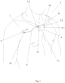
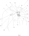
- the fastening system (1) for an electrical stimulation generator (2) comprises a generator (2) for cardiac stimulation, such as a pacemaker, a defibrillator, a resynchronizer, a neurostimulation mechanism or another similar generator disposed externally with respect to the body of the patient (3) and an electrode (5) that presents a first end (5.1) for connection to the heart of the patient (3) and a second end (5.2) for connection to said generator (2) .
- a generator (2) for cardiac stimulation such as a pacemaker, a defibrillator, a resynchronizer, a neurostimulation mechanism or another similar generator disposed externally with respect to the body of the patient (3) and an electrode (5) that presents a first end (5.1) for connection to the heart of the patient (3) and a second end (5.2) for connection to said generator (2) .
- This device comprises a casing (4) for containing said generator (2) therein, means for the connection of the electrode (5), an airtight closing element (10), a device (6) for securing the electrode (5) to the skin, and means for fastening the casing (4) to the body of the patient (3).
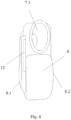
- the casing (4) presents identical first and second openings (7.1, 7.2) disposed on opposite sides thereof.
- the casing (4) is formed by a rear part (8.1) in contact with the body of the patient (3) and a front part (8.2), joined together by hinged means (9), and comprises closing means at an end opposite the hinged means (9).
- these closing means consist of the fitting of the first connector (13) in the first opening (7.1) of the casing (4) and the fitting of the closing element (10) in the second opening (7.2) thereof. Said fitting of both allows keeping both the rear part and the front part (8.1, 8.2) of the casing (4) joined to one another.
- the means for fastening the casing (4) to the body of the patient (3) are formed by a longitudinal and flexible strap (11) suitable for placement thereof around the neck of the patient (3) like a necklace.
- the casing (4) comprises on the external surface of the rear part (8.1) an eyelet (12) suitable for holding the longitudinal strap (11) therein.
- the strap (11) is therefore passed through the eyelet (12) of the casing (4) and is firmly secured to the neck of the patient (3).
- the means for the connection of the electrode (5) are formed by a first pass-through connector (13) for the second end (5.2) of the electrode (5), having an airtight valve (14) therein.
- the electrode (5) is connected to the generator (2) through the first opening (7.1), so the first connector (13) is disposed in said first opening (7.1), but in the case in which the connection is to be made on the other side of the patient's body, the electrode (5) would be connected through the second opening (7.2).
- the electrode (5) comprises a sheath for covering same, in the externalized part thereof, between the point where it comes out through the first opening (7.1) of the casing (4), in this case, until the second connector (19) for anchoring to the device (6) for securing to the skin.
- the sheath is furthermore preferably formed by a plastic material having retractable properties.
- the airtight valve (14) of the first connector (13) comprises internal disks (15) allowing the passage of the electrode (5) while at the same time providing airtightness to said first opening (7.1) in this case.
- the electrode (5) is connected to the generator (2) through the first opening (7.1), it is the second opening (7.2) of the casing (4) which presents an airtight closing element (10).
- the device (6) for securing the electrode (5) to the skin presents means for anchoring to said electrode (5) and means for adhering to the torso of the patient (3).
- the device (6) for securing to the skin has a tubular shape with first and second ends (6.1, 6.2) and at least one semicircular segment (16) between them.
- this device (6) for securing to the skin comprises two additional straight segments (17) between the semicircular segment (16) and the first and second ends (6.1, 6.2), respectively, of said device (6) for securing to the skin, as can be seen in said figures.
- Figures 5 and 7 show that the device (6) for securing to the skin comprises a groove (18) communicating the inside of the device (6) for securing to the skin with the outside along the entire length thereof between both first and second ends (6.1, 6.2).
- the dimensions of said groove (18) are such that they allow the introduction of the electrode (5) inside the entire tubular path of the device (6) for securing to the skin from the first end (6.1) to the second end (6.2) thereof.
- the means for anchoring the electrode (5) to the device (6) for securing to the skin are formed by a second connector (19), shown in Figures 6.1, 6.2 , and 7 , suitable for connection thereof in the first or second end (6.1, 6.2) of said device (6) for securing to the skin, in this case the first end (6.1) thereof.
- This second connector (19) presents first notches (20) on its inner surface, whereas the first and second ends (6.1, 6.2) of the device (6) for securing to the skin present on their outer surface second notches (21) suitable for fitting with the first notches (20) of said second connector (19).
- the means for adhering the device (6) for securing to the skin are formed by a protruding element (22) which protrudes from the semicircular segment (16) of said device (6) for securing to the skin, with a face (22.1) opposite said semicircular segment (16) and with an adhesive thereon.
- this device (6) for securing to the skin comprises means for tying the electrode (5) thereto, so as to fix the electrode (5) even more firmly to said device.
- These means for tying are formed by a silk thread or the like (not depicted in the figures), a third notch (23) around the contour of the central section of the semicircular segment (16), and a through hole (24) disposed between said notch and the protruding element (22) of the means for adhering such that it coincides with said third notch (23).
- This third notch (23) is suitable for the fitting of said silk thread and for tying same around the electrode (5).
- a silk thread can therefore be passed through the through hole (24) and is fitted in the third notch (23) so that, when it is tied, the thread constricts the electrode (5), fixing it in place inside the groove (18) of the device (6) for securing to the skin.
- the system (1) further comprises a padded element (25) on the inner surface of both front and rear parts (8.1, 8.2) to thereby dampen the contact of the generator (2) with said front and rear parts (8.1, 8.2) of the casing (4).
Landscapes
- Health & Medical Sciences (AREA)
- Animal Behavior & Ethology (AREA)
- Biomedical Technology (AREA)
- Nuclear Medicine, Radiotherapy & Molecular Imaging (AREA)
- Radiology & Medical Imaging (AREA)
- Life Sciences & Earth Sciences (AREA)
- Engineering & Computer Science (AREA)
- General Health & Medical Sciences (AREA)
- Public Health (AREA)
- Veterinary Medicine (AREA)
- Heart & Thoracic Surgery (AREA)
- Cardiology (AREA)
- Electrotherapy Devices (AREA)
Claims (13)
- Befestigungssystem (1) für einen Generator von elektrischer Stimulation (2), umfassend einen Generator (2) für Herzstimulation, wie einen Schrittmacher, einen Defibrillator, einen Resynchronisierer; einen Neurostimulationsmechanismus oder einen anderen ähnlichen Generator, welcher äußerlich in Bezug auf den Körper des Patienten (3) angeordnet ist, und eine Elektrode (5), welche ein erstes Ende (5.1) für den Anschluss an das Herz des Patienten (3) und ein zweites Ende (5.2) für den Anschluss an den genannten Generator (2) aufweist, dadurch gekennzeichnet, dass es zusätzlich Folgendes umfasst:- ein Gehäuse (4) zum Enthalten des Generators (2) darin, welches identische erste und zweite Öffnungen (7.1, 7.2) aufweist, welche auf gegenüberliegenden Seiten desselben angeordnet sind;- Mittel für den Anschluss der Elektrode (5) an die erste oder zweite Öffnung (7.1, 7.2) im Gehäuse (4), gebildet aus einem ersten Durchgangsanschlussstück (13) für das zweite Ende (5.2) der Elektrode (5), wobei das erste Anschlussstück (13) darin ein luftdichtes Ventil (14) aufweist;- an luftdichtes Schließelement (10) angeordnet an der Öffnung des Gehäuses (4), welche derjenigen aufweisend die Mittel für den Anschluss der Elektrode (5) gegenüberliegt;- eine Vorrichtung (6) zum Sichern der Elektrode (5) an der Haut, aufweisend Mittel zur Verankerung an der genannten Elektrode (5) und Mittel zur Anhaftung am Oberkörper des Patienten (3); und- Mittel zur Befestigung des Gehäuses (4) am Körper des Patienten (3);wobei das Gehäuse (4) aus einem Hinterteil (8.1) in Kontakt mit dem Körper des Patienten (3) und einem Vorderteil (8.2), miteinander durch Scharniermittel (9) verbunden, gebildet ist und Schließmittel an einem Ende, welches den Scharniermitteln (9) gegenüberliegt, mittels des Einpassens des ersten Anschlussstücks (13) und des Schließelements (10) sowohl in die erste als auch in die zweite Öffnung (7.1, 7.2) des Gehäuses (4), jeweils in eine der genannten Öffnungen; wobei die Stellungen des Schließelements (10) und des ersten Anschlussstücks (13) gegenseitig austauschbar sind, sodass es der Elektrode (5) erlaubt wird, sich an die erste Öffnung (7.1) oder an die zweite Öffnung (7.2) anschließen zu können.
- System nach Anspruch 1, wobei die Vorrichtung (6) zur Sicherung an der Haut eine rohrförmige Gestalt mit ersten und zweiten Enden (6.1, 6.2) und mindestens einem halbkreisförmigen Segment (16) dazwischen aufweist, wobei die Vorrichtung (6) zur Sicherung an der Haut eine Nut (18) umfasst, welche das innere der Vorrichtung (6) zur Sicherung an der Haut mit dem Äußeren entlang der gesamten Länge derselben zwischen sowohl dem ersten als auch dem zweiten Ende (6.1, 6.2) kommuniziert, wobei die Abmessungen der Nut (18) so sind, dass sie das Einpassen der Elektrode (5) innerhalb der Vorrichtung (6) zur Sicherung an der Haut vom ersten Ende (6.1) zum zweiten Ende (6.2) derselben erlaubt.
- System nach Anspruch 2, wobei die Mittel zur Verankerung der Elektrode (5) an der Vorrichtung (6) zur Sicherung an der Haut aus einem zweiten Anschlussstück (19) gebildet sind, welches für den Anschluss desselben an das erste oder zweite Ende (6.1, 6.2) der genannten Vorrichtung (6) zur Sicherung an der Haut geeignet ist, wobei das zweite Anschlussstück (19) erste Einkerbungen (20) auf dessen Innenfläche aufweist, und die ersten und zweite Enden (6.1, 6.2) der genannten Vorrichtung (6) zur Sicherung an der Haut auf deren Außenfläche zweite Einkerbungen (21) aufweisen, welche für das Einpassen mit den ersten Einkerbungen (20) des zweiten Anschlussstücks (19) geeignet sind.
- System (1) nach Anspruch 1, wobei die Mittel zur Anhaftung aus einem vorstehenden Element (22) gebildet sind, welches vom halbkreisförmigen Segment (16) der Vorrichtung (6) zur Sicherung an der Haut vorsteht, mit einer dem genannten halbkreisförmigen Segment (16) gegenüberliegenden Fläche (22.1) und mit einem Haftmittel darauf.
- System nach einem der vorhergehenden Ansprüche, wobei die Vorrichtung (6) zur Sicherung an der Haut Mittel zum Binden der Elektrode (5) daran umfasst.
- System nach Anspruch 5, wobei die Mittel zum Binden der Elektrode (5) aus einem Seidenfaden oder ähnlichem, einer dritten Einkerbung (23) um die Kontur eines mittleren Abschnitts des halbkreisförmigen Segments (16) herum und einem Durchgangsloch (24), welches zwischen der dritten Einkerbung und dem vorstehenden Element (22) der Mittel zur Anhaftung angeordnet ist, sodass es mit der genannten dritten Einkerbung (23) übereinstimmt, gebildet sind, und wobei die dritte Einkerbung (23) für das Einpassen des genannten Seidenfadens und zum Binden desselben um die Elektrode (5) herum geeignet ist.
- System nach einem der Ansprüche 2 bis 6, wobei die Vorrichtung (6) zur Sicherung an der Haut zwei zusätzliche geradlinige Segmente (17) jeweils zwischen dem kreisförmigen Segment (16) und den ersten und zweiten Enden (6.1, 6.2) der genannten Vorrichtung (6) zur Sicherung an der Haut umfasst.
- System nach einem der vorhergehenden Ansprüche, wobei das luftdichte Ventil (14) des ersten Anschlussstücks (13) innere Scheiben (15) umfasst, welche den Durchgang der Elektrode (5) erlauben.
- System nach einem der vorhergehenden Ansprüche, wobei die Mittel zur Befestigung des Gehäuses (4) am Körper des Patienten (3) aus einem länglichen und flexiblen Band (11) gebildet sind, welches für das Platzieren desselben um den Hals des Patienten (3) herum wie eine Halskette geeignet ist.
- System nach Anspruch 9, wobei das Gehäuse (4) auf der Außenfläche des Hinterteils (8.1) eine Öse (12) umfasst, welche für das Halten des länglichen Bandes (11) darin geeignet ist.
- System nach einem der vorhergehenden Ansprüche, wobei die Elektrode (5) eine Hülle umfasst, für das Decken derselben vom Punkt aus, in welchem sie vom Gehäuse (4) durch das erste Anschlussstück (13) herauskommt, bis sie an der Vorrichtung (6) zur Sicherung an der Haut mittels des zweiten Anschlussstücks (19) angeschlossen ist.
- System nach Anspruch 11, wobei die Hülle aus einem Kunststoffmaterial gebildet ist und einziehbare Eigenschaften aufweist.
- System nach einem der vorhergehenden Ansprüche, zusätzlich umfassend ein gepolstertes Element (25) auf der Innenfläche sowohl des Vorder- als auch des Hinterteils (8.1, 8.2) des Gehäuses (4).
Applications Claiming Priority (2)
| Application Number | Priority Date | Filing Date | Title |
|---|---|---|---|
| ES201930723A ES2804080B2 (es) | 2019-08-02 | 2019-08-02 | Sistema de sujeción para generador de estimulación eléctrica |
| PCT/ES2020/070464 WO2021023901A1 (es) | 2019-08-02 | 2020-07-17 | Sistema de sujeción para generador de estimulación eléctrica |
Publications (4)
| Publication Number | Publication Date |
|---|---|
| EP4008396A1 EP4008396A1 (de) | 2022-06-08 |
| EP4008396A4 EP4008396A4 (de) | 2023-08-23 |
| EP4008396C0 EP4008396C0 (de) | 2024-11-20 |
| EP4008396B1 true EP4008396B1 (de) | 2024-11-20 |
Family
ID=74246702
Family Applications (1)
| Application Number | Title | Priority Date | Filing Date |
|---|---|---|---|
| EP20849457.5A Active EP4008396B1 (de) | 2019-08-02 | 2020-07-17 | Befestigungssystem für einen generator von elektrischer stimulation |
Country Status (7)
| Country | Link |
|---|---|
| US (2) | US11975201B2 (de) |
| EP (1) | EP4008396B1 (de) |
| CN (1) | CN114206433B (de) |
| AU (1) | AU2020325726B2 (de) |
| CA (1) | CA3145450A1 (de) |
| ES (1) | ES2804080B2 (de) |
| WO (1) | WO2021023901A1 (de) |
Citations (2)
| Publication number | Priority date | Publication date | Assignee | Title |
|---|---|---|---|---|
| US8843200B2 (en) * | 2010-04-29 | 2014-09-23 | Medtronic, Inc. | Neurological screening connector |
| WO2018156953A1 (en) * | 2017-02-24 | 2018-08-30 | Nalu Medical, Inc. | Apparatus with sequentially implanted stimulators |
Family Cites Families (23)
| Publication number | Priority date | Publication date | Assignee | Title |
|---|---|---|---|---|
| US4966319A (en) * | 1989-11-02 | 1990-10-30 | Jim Fleming Communications | Orthodontal device carrying case with neck strap |
| US5328442A (en) * | 1992-11-20 | 1994-07-12 | Siemens Pacesetter, Inc. | System and method for stimulating a heart having undergone cardiac myoplasty using a single-chamber pacemaker |
| US5545189A (en) * | 1995-11-02 | 1996-08-13 | Ventritex, Inc. | Case-activating switch assembly for an implantable cardiac stimulation device |
| US5679026A (en) * | 1995-12-21 | 1997-10-21 | Ventritex, Inc. | Header adapter for an implantable cardiac stimulation device |
| US6065154A (en) * | 1998-04-07 | 2000-05-23 | Lifecor, Inc. | Support garments for patient-worn energy delivery apparatus |
| SE9803692D0 (sv) * | 1998-10-27 | 1998-10-27 | Pacesetter Ab | A connector for a heart stimulator |
| US6622046B2 (en) * | 2001-05-07 | 2003-09-16 | Medtronic, Inc. | Subcutaneous sensing feedthrough/electrode assembly |
| CN100394896C (zh) * | 2004-12-31 | 2008-06-18 | 田亚华 | 永久性心脏起搏器植入术后压迫止血及囊袋保护装置 |
| US8103347B2 (en) * | 2007-04-25 | 2012-01-24 | Advanced Neuromodulation Systems, Inc. | Implantable pulse generator comprising MRI current limiting windings in header structure |
| KR101033749B1 (ko) * | 2009-08-13 | 2011-05-09 | 국립암센터 | 체내이식용 전기자극장치의 커넥터조립체 및 이를 포함하는 전기자극장치 |
| US8834426B2 (en) * | 2009-10-27 | 2014-09-16 | Russell Shipman | Catheter and tubing restraining device and protective cover |
| US8401670B2 (en) * | 2010-04-30 | 2013-03-19 | Medtronic, Inc. | Neurological screening connector |
| WO2014093371A1 (en) * | 2012-12-14 | 2014-06-19 | Boston Scientific Neuromodulation Corporation | Systems and methods for making and using contact assemblies for leads of electrical stimulation systems |
| DE102013200151A1 (de) * | 2013-01-08 | 2014-07-10 | AdjuCor GmbH | Herzunterstützungsvorrichtung mit Markierungen |
| CA2930809A1 (en) * | 2013-11-22 | 2015-05-28 | Simon Fraser University | Apparatus and methods for assisted breathing by transvascular nerve stimulation |
| US9895531B2 (en) * | 2014-04-11 | 2018-02-20 | Pacesetter, Inc. | Protective patch for protecting the implant site of a trial neurostimulation lead |
| EP3180071B1 (de) * | 2014-08-15 | 2021-09-22 | Axonics, Inc. | Externe impulsgeneratorvorrichtung und zugehörige system zur versuchsnervenstimulation |
| US20160067502A1 (en) * | 2014-09-04 | 2016-03-10 | Pacesetter, Inc. | Enclosure for protecting a trial neurostimulation generator from contamination |
| ES2583159B1 (es) * | 2015-02-17 | 2017-04-28 | Ionclinics And Deionic, S.L. | Dispositivo para el diagnóstico y regeneración inducida en tejidos mediante electrolisis percutánea terapéutica y electro-estimulación focalizada con aguja bipolar |
| GB2552656A (en) * | 2016-07-29 | 2018-02-07 | Univ Central Lancashire | A tube stabilising device |
| CN110234392B (zh) * | 2017-01-26 | 2023-08-11 | 心脏起搏器股份公司 | 具有被包覆模制的组件的无引线装置 |
| NL2019577B1 (en) * | 2017-09-19 | 2019-03-28 | Cardiac Pacemakers Inc | Stimulation/sensing electrode fixation device and electrical lead |
| CN108671400A (zh) * | 2018-06-12 | 2018-10-19 | 李长寿 | 一种心脏急救起搏器 |
-
2019
- 2019-08-02 ES ES201930723A patent/ES2804080B2/es active Active
-
2020
- 2020-07-17 CA CA3145450A patent/CA3145450A1/en active Pending
- 2020-07-17 AU AU2020325726A patent/AU2020325726B2/en active Active
- 2020-07-17 CN CN202080054598.6A patent/CN114206433B/zh active Active
- 2020-07-17 EP EP20849457.5A patent/EP4008396B1/de active Active
- 2020-07-17 US US17/624,392 patent/US11975201B2/en active Active
- 2020-07-17 WO PCT/ES2020/070464 patent/WO2021023901A1/es not_active Ceased
-
2024
- 2024-02-06 US US18/433,686 patent/US20240173552A1/en not_active Abandoned
Patent Citations (2)
| Publication number | Priority date | Publication date | Assignee | Title |
|---|---|---|---|---|
| US8843200B2 (en) * | 2010-04-29 | 2014-09-23 | Medtronic, Inc. | Neurological screening connector |
| WO2018156953A1 (en) * | 2017-02-24 | 2018-08-30 | Nalu Medical, Inc. | Apparatus with sequentially implanted stimulators |
Also Published As
| Publication number | Publication date |
|---|---|
| WO2021023901A1 (es) | 2021-02-11 |
| EP4008396C0 (de) | 2024-11-20 |
| AU2020325726B2 (en) | 2025-04-24 |
| AU2020325726A1 (en) | 2022-02-10 |
| CN114206433A (zh) | 2022-03-18 |
| ES2804080B2 (es) | 2021-08-05 |
| EP4008396A4 (de) | 2023-08-23 |
| CA3145450A1 (en) | 2021-02-11 |
| ES2804080A1 (es) | 2021-02-03 |
| US11975201B2 (en) | 2024-05-07 |
| US20220347472A1 (en) | 2022-11-03 |
| US20240173552A1 (en) | 2024-05-30 |
| CN114206433B (zh) | 2025-11-18 |
| EP4008396A1 (de) | 2022-06-08 |
Similar Documents
| Publication | Publication Date | Title |
|---|---|---|
| US9814889B2 (en) | Injectable subcutaneous string heart device | |
| US8239045B2 (en) | Device and method for retaining a medical device within a vessel | |
| US7734343B2 (en) | Implantable intravascular device for defibrillation and/or pacing | |
| JP6454728B2 (ja) | 植え込み型医療装置、システム、及びそれらの構成要素 | |
| US10434316B2 (en) | Flexible rechargeable implantable subcutaneous medical device structure and method of assembly | |
| JPH0534027B2 (de) | ||
| JPH0571269B2 (de) | ||
| JP2008540052A (ja) | 心臓リード線による体腔整形器具 | |
| JP2005515852A (ja) | 耐mri電極システムのための遮蔽被膜の方法及び装置 | |
| US12311165B2 (en) | Implantable endovascular, low profile intracardiac left atrial restraining devices for low energy atrial cardioversion, pacing and sensing | |
| US9895531B2 (en) | Protective patch for protecting the implant site of a trial neurostimulation lead | |
| IL262714B (en) | Flexible semi-hermetic implantable medical device structure | |
| EP4482566A2 (de) | Fortschrittliche implantierbare endovaskuläre intrakardiale linksatriale rückhaltevorrichtungen mit niedrigem profil für vorhofkardioversion, -stimulation und -messung mit niedriger energie | |
| US20160067502A1 (en) | Enclosure for protecting a trial neurostimulation generator from contamination | |
| EP4008396B1 (de) | Befestigungssystem für einen generator von elektrischer stimulation | |
| US10786668B2 (en) | Protective sheath and method for protecting a lead during implant and pulse generator replacement | |
| RU2815893C2 (ru) | Крепежная система для генератора электростимуляции | |
| Rivner et al. | Implantable Cardioverter Defibrillators (ICD) | |
| Gomez | Implantable Cardioverter Defibrillators (ICD) |
Legal Events
| Date | Code | Title | Description |
|---|---|---|---|
| STAA | Information on the status of an ep patent application or granted ep patent |
Free format text: STATUS: THE INTERNATIONAL PUBLICATION HAS BEEN MADE |
|
| PUAI | Public reference made under article 153(3) epc to a published international application that has entered the european phase |
Free format text: ORIGINAL CODE: 0009012 |
|
| STAA | Information on the status of an ep patent application or granted ep patent |
Free format text: STATUS: REQUEST FOR EXAMINATION WAS MADE |
|
| 17P | Request for examination filed |
Effective date: 20220203 |
|
| AK | Designated contracting states |
Kind code of ref document: A1 Designated state(s): AL AT BE BG CH CY CZ DE DK EE ES FI FR GB GR HR HU IE IS IT LI LT LU LV MC MK MT NL NO PL PT RO RS SE SI SK SM TR |
|
| DAV | Request for validation of the european patent (deleted) | ||
| DAX | Request for extension of the european patent (deleted) | ||
| P01 | Opt-out of the competence of the unified patent court (upc) registered |
Effective date: 20230601 |
|
| A4 | Supplementary search report drawn up and despatched |
Effective date: 20230720 |
|
| RIC1 | Information provided on ipc code assigned before grant |
Ipc: A61M 25/02 20060101ALI20230714BHEP Ipc: A61M 39/12 20060101ALI20230714BHEP Ipc: A61N 1/375 20060101ALI20230714BHEP Ipc: A61N 1/39 20060101ALI20230714BHEP Ipc: A61N 1/362 20060101AFI20230714BHEP |
|
| GRAP | Despatch of communication of intention to grant a patent |
Free format text: ORIGINAL CODE: EPIDOSNIGR1 |
|
| STAA | Information on the status of an ep patent application or granted ep patent |
Free format text: STATUS: GRANT OF PATENT IS INTENDED |
|
| INTG | Intention to grant announced |
Effective date: 20240618 |
|
| GRAS | Grant fee paid |
Free format text: ORIGINAL CODE: EPIDOSNIGR3 |
|
| GRAA | (expected) grant |
Free format text: ORIGINAL CODE: 0009210 |
|
| STAA | Information on the status of an ep patent application or granted ep patent |
Free format text: STATUS: THE PATENT HAS BEEN GRANTED |
|
| AK | Designated contracting states |
Kind code of ref document: B1 Designated state(s): AL AT BE BG CH CY CZ DE DK EE ES FI FR GB GR HR HU IE IS IT LI LT LU LV MC MK MT NL NO PL PT RO RS SE SI SK SM TR |
|
| REG | Reference to a national code |
Ref country code: GB Ref legal event code: FG4D |
|
| REG | Reference to a national code |
Ref country code: CH Ref legal event code: EP |
|
| REG | Reference to a national code |
Ref country code: DE Ref legal event code: R096 Ref document number: 602020041818 Country of ref document: DE |
|
| REG | Reference to a national code |
Ref country code: IE Ref legal event code: FG4D |
|
| U01 | Request for unitary effect filed |
Effective date: 20241203 |
|
| P04 | Withdrawal of opt-out of the competence of the unified patent court (upc) registered |
Free format text: CASE NUMBER: APP_65299/2024 Effective date: 20241210 |
|
| U07 | Unitary effect registered |
Designated state(s): AT BE BG DE DK EE FI FR IT LT LU LV MT NL PT RO SE SI Effective date: 20241213 |
|
| PG25 | Lapsed in a contracting state [announced via postgrant information from national office to epo] |
Ref country code: HR Free format text: LAPSE BECAUSE OF FAILURE TO SUBMIT A TRANSLATION OF THE DESCRIPTION OR TO PAY THE FEE WITHIN THE PRESCRIBED TIME-LIMIT Effective date: 20241120 Ref country code: IS Free format text: LAPSE BECAUSE OF FAILURE TO SUBMIT A TRANSLATION OF THE DESCRIPTION OR TO PAY THE FEE WITHIN THE PRESCRIBED TIME-LIMIT Effective date: 20250320 |
|
| PG25 | Lapsed in a contracting state [announced via postgrant information from national office to epo] |
Ref country code: ES Free format text: LAPSE BECAUSE OF FAILURE TO SUBMIT A TRANSLATION OF THE DESCRIPTION OR TO PAY THE FEE WITHIN THE PRESCRIBED TIME-LIMIT Effective date: 20241120 |
|
| PG25 | Lapsed in a contracting state [announced via postgrant information from national office to epo] |
Ref country code: NO Free format text: LAPSE BECAUSE OF FAILURE TO SUBMIT A TRANSLATION OF THE DESCRIPTION OR TO PAY THE FEE WITHIN THE PRESCRIBED TIME-LIMIT Effective date: 20250220 |
|
| PG25 | Lapsed in a contracting state [announced via postgrant information from national office to epo] |
Ref country code: GR Free format text: LAPSE BECAUSE OF FAILURE TO SUBMIT A TRANSLATION OF THE DESCRIPTION OR TO PAY THE FEE WITHIN THE PRESCRIBED TIME-LIMIT Effective date: 20250221 |
|
| PG25 | Lapsed in a contracting state [announced via postgrant information from national office to epo] |
Ref country code: PL Free format text: LAPSE BECAUSE OF FAILURE TO SUBMIT A TRANSLATION OF THE DESCRIPTION OR TO PAY THE FEE WITHIN THE PRESCRIBED TIME-LIMIT Effective date: 20241120 |
|
| PG25 | Lapsed in a contracting state [announced via postgrant information from national office to epo] |
Ref country code: RS Free format text: LAPSE BECAUSE OF FAILURE TO SUBMIT A TRANSLATION OF THE DESCRIPTION OR TO PAY THE FEE WITHIN THE PRESCRIBED TIME-LIMIT Effective date: 20250220 |
|
| PG25 | Lapsed in a contracting state [announced via postgrant information from national office to epo] |
Ref country code: SM Free format text: LAPSE BECAUSE OF FAILURE TO SUBMIT A TRANSLATION OF THE DESCRIPTION OR TO PAY THE FEE WITHIN THE PRESCRIBED TIME-LIMIT Effective date: 20241120 |
|
| U20 | Renewal fee for the european patent with unitary effect paid |
Year of fee payment: 6 Effective date: 20250612 |
|
| PG25 | Lapsed in a contracting state [announced via postgrant information from national office to epo] |
Ref country code: SK Free format text: LAPSE BECAUSE OF FAILURE TO SUBMIT A TRANSLATION OF THE DESCRIPTION OR TO PAY THE FEE WITHIN THE PRESCRIBED TIME-LIMIT Effective date: 20241120 |
|
| PG25 | Lapsed in a contracting state [announced via postgrant information from national office to epo] |
Ref country code: CZ Free format text: LAPSE BECAUSE OF FAILURE TO SUBMIT A TRANSLATION OF THE DESCRIPTION OR TO PAY THE FEE WITHIN THE PRESCRIBED TIME-LIMIT Effective date: 20241120 |
|
| PLBE | No opposition filed within time limit |
Free format text: ORIGINAL CODE: 0009261 |
|
| STAA | Information on the status of an ep patent application or granted ep patent |
Free format text: STATUS: NO OPPOSITION FILED WITHIN TIME LIMIT |
|
| PGFP | Annual fee paid to national office [announced via postgrant information from national office to epo] |
Ref country code: GB Payment date: 20250728 Year of fee payment: 6 |
|
| 26N | No opposition filed |
Effective date: 20250821 |
|
| REG | Reference to a national code |
Ref country code: CH Ref legal event code: H13 Free format text: ST27 STATUS EVENT CODE: U-0-0-H10-H13 (AS PROVIDED BY THE NATIONAL OFFICE) Effective date: 20260224 |
|
| PG25 | Lapsed in a contracting state [announced via postgrant information from national office to epo] |
Ref country code: CH Free format text: LAPSE BECAUSE OF NON-PAYMENT OF DUE FEES Effective date: 20250731 |