EP4008394B1 - Mikrostrompflaster - Google Patents
Mikrostrompflaster Download PDFInfo
- Publication number
- EP4008394B1 EP4008394B1 EP20849880.8A EP20849880A EP4008394B1 EP 4008394 B1 EP4008394 B1 EP 4008394B1 EP 20849880 A EP20849880 A EP 20849880A EP 4008394 B1 EP4008394 B1 EP 4008394B1
- Authority
- EP
- European Patent Office
- Prior art keywords
- circuit
- patch
- small
- base
- sized battery
- Prior art date
- Legal status (The legal status is an assumption and is not a legal conclusion. Google has not performed a legal analysis and makes no representation as to the accuracy of the status listed.)
- Active
Links
Images



Classifications
-
- A—HUMAN NECESSITIES
- A61—MEDICAL OR VETERINARY SCIENCE; HYGIENE
- A61N—ELECTROTHERAPY; MAGNETOTHERAPY; RADIATION THERAPY; ULTRASOUND THERAPY
- A61N1/00—Electrotherapy; Circuits therefor
- A61N1/02—Details
- A61N1/04—Electrodes
- A61N1/0404—Electrodes for external use
- A61N1/0472—Structure-related aspects
- A61N1/0492—Patch electrodes
- A61N1/0496—Patch electrodes characterised by using specific chemical compositions, e.g. hydrogel compositions, adhesives
-
- A—HUMAN NECESSITIES
- A61—MEDICAL OR VETERINARY SCIENCE; HYGIENE
- A61N—ELECTROTHERAPY; MAGNETOTHERAPY; RADIATION THERAPY; ULTRASOUND THERAPY
- A61N1/00—Electrotherapy; Circuits therefor
- A61N1/02—Details
- A61N1/04—Electrodes
- A61N1/0404—Electrodes for external use
- A61N1/0472—Structure-related aspects
- A61N1/0492—Patch electrodes
-
- A—HUMAN NECESSITIES
- A61—MEDICAL OR VETERINARY SCIENCE; HYGIENE
- A61N—ELECTROTHERAPY; MAGNETOTHERAPY; RADIATION THERAPY; ULTRASOUND THERAPY
- A61N1/00—Electrotherapy; Circuits therefor
- A61N1/02—Details
-
- A—HUMAN NECESSITIES
- A61—MEDICAL OR VETERINARY SCIENCE; HYGIENE
- A61N—ELECTROTHERAPY; MAGNETOTHERAPY; RADIATION THERAPY; ULTRASOUND THERAPY
- A61N1/00—Electrotherapy; Circuits therefor
- A61N1/02—Details
- A61N1/025—Digital circuitry features of electrotherapy devices, e.g. memory, clocks, processors
-
- A—HUMAN NECESSITIES
- A61—MEDICAL OR VETERINARY SCIENCE; HYGIENE
- A61N—ELECTROTHERAPY; MAGNETOTHERAPY; RADIATION THERAPY; ULTRASOUND THERAPY
- A61N1/00—Electrotherapy; Circuits therefor
- A61N1/02—Details
- A61N1/04—Electrodes
-
- A—HUMAN NECESSITIES
- A61—MEDICAL OR VETERINARY SCIENCE; HYGIENE
- A61N—ELECTROTHERAPY; MAGNETOTHERAPY; RADIATION THERAPY; ULTRASOUND THERAPY
- A61N1/00—Electrotherapy; Circuits therefor
- A61N1/18—Applying electric currents by contact electrodes
- A61N1/32—Applying electric currents by contact electrodes alternating or intermittent currents
- A61N1/36—Applying electric currents by contact electrodes alternating or intermittent currents for stimulation
-
- A—HUMAN NECESSITIES
- A61—MEDICAL OR VETERINARY SCIENCE; HYGIENE
- A61N—ELECTROTHERAPY; MAGNETOTHERAPY; RADIATION THERAPY; ULTRASOUND THERAPY
- A61N1/00—Electrotherapy; Circuits therefor
- A61N1/18—Applying electric currents by contact electrodes
- A61N1/32—Applying electric currents by contact electrodes alternating or intermittent currents
- A61N1/36—Applying electric currents by contact electrodes alternating or intermittent currents for stimulation
- A61N1/36014—External stimulators, e.g. with patch electrodes
-
- A—HUMAN NECESSITIES
- A61—MEDICAL OR VETERINARY SCIENCE; HYGIENE
- A61N—ELECTROTHERAPY; MAGNETOTHERAPY; RADIATION THERAPY; ULTRASOUND THERAPY
- A61N1/00—Electrotherapy; Circuits therefor
- A61N1/18—Applying electric currents by contact electrodes
- A61N1/20—Applying electric currents by contact electrodes continuous direct currents
- A61N1/205—Applying electric currents by contact electrodes continuous direct currents for promoting a biological process
-
- H—ELECTRICITY
- H01—ELECTRIC ELEMENTS
- H01B—CABLES; CONDUCTORS; INSULATORS; SELECTION OF MATERIALS FOR THEIR CONDUCTIVE, INSULATING OR DIELECTRIC PROPERTIES
- H01B3/00—Insulators or insulating bodies characterised by the insulating materials; Selection of materials for their insulating or dielectric properties
- H01B3/18—Insulators or insulating bodies characterised by the insulating materials; Selection of materials for their insulating or dielectric properties mainly consisting of organic substances
- H01B3/30—Insulators or insulating bodies characterised by the insulating materials; Selection of materials for their insulating or dielectric properties mainly consisting of organic substances plastics; resins; waxes
- H01B3/42—Insulators or insulating bodies characterised by the insulating materials; Selection of materials for their insulating or dielectric properties mainly consisting of organic substances plastics; resins; waxes polyesters; polyethers; polyacetals
- H01B3/427—Polyethers
Definitions
- the present disclosure relates to a microcurrent patch. More specifically, the present disclosure relates to a microcurrent patch in which a small-sized battery and a circuit are disposed on the base and the small-sized battery and the circuit on the base are covered with a glue layer, such that when the patch is attached to a human body, microcurrent flows through skin.
- microcurrent When a microcurrent flows through the human body.
- Applying microcurrent to the human body is known to have effects such as activating metabolism and blood circulation, improving body functions such as increasing immunity, pain relief, cell regeneration and hormone secretion promotion.
- effects such as activating metabolism and blood circulation, improving body functions such as increasing immunity, pain relief, cell regeneration and hormone secretion promotion.
- products using various types of microcurrents are disclosed.
- Korean Patent No. 10-1423241 discloses a microcurrent generating patch.
- Japan Patent No. 2016516549 discloses a system for treating biological wounded tissue.
- This document proposes a configuration in which a first metal and a second metal having different materials are respectively attached to both sides of an adhesive layer of the patch so that microcurrent is generated in the patch when the patch is attached to the body.
- an electrode made of a metal component interacts with a human body fluid acting as an electrolyte to generate a current. Flexibility is remarkably reduced and current is lost.
- a purpose of the present disclosure is to provide a microcurrent patch in which a small-sized battery and a circuit are disposed on a base, and the small-sized battery and the circuit on the base are covered with a glue layer to form a singe body, and thus it is convenient to use the patch.
- Another purpose of the present disclosure is to provide a microcurrent patch that is easily attached to a curved human body because the patch has excellent flexibility.
- another purpose of the present disclosure is to provide a microcurrent patch capable of controlling an amount of current flowing through the patch based on a linear width of the circuit or the number of holes in the glue layer.
- a microcurrent patch according to the present disclosure includes: a base made of a polymer film;
- the base includes one or more components from a group consisting of polyethylene naphthalate (PEN), and polyethylene terephthalate (PET).
- PEN polyethylene naphthalate
- PET polyethylene terephthalate
- the small-sized battery includes at least two small-sized batteries arranged in a parallel manner and disposed on the base.
- the small-sized battery includes at least two small-sized batteries arranged in a series manner and disposed on the base.
- the circuit is electrically connected to the small-sized battery, wherein the circuit is divided into a circuit portion connected to a positive terminal of the small-sized battery and a circuit portion connected to a negative terminal thereof.
- the circuit has a structure in a form of a mesh intersecting with each other.
- the circuit is formed in a linear shape, and a linear width of the linear shape is in a range of 0.01 to 10mm.
- the circuit includes one or more components selected from a group consisting of carbon, nickel, silver, aluminum, copper, and gold.
- Each of both opposing faces of the glue layer is made of an adhesive material and has insulation ability.
- the glue layer is made of acrylate, and has a thickness of 0.01 ⁇ m to 1,000 ⁇ m.
- the small-sized battery and the circuit are disposed on the base, and the small-sized battery and the circuit on the base are covered with the glue layer to form a single body.
- the glue layer to form a single body.
- microcurrent patch according to the present disclosure has excellent flexibility, and may be easily attached to a curved human body, thereby providing use convenience.
- the microcurrent patch may control the amount of current flowing through the patch based on the linear width of the circuit or the number of holes in the glue layer. Further, a total voltage and a total capacity of the batteries may be easily adjusted based on the number of series or parallel connected small-sized batteries.
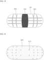
- Amicrocurrent patch according to the present disclosure is attached to the human body and is configured to generate microcurrent and flow the same through the skin, and is composed of a base 100, a small-sized battery 200, a circuit 300, and a glue layer 400.
- the base 100 is made of a soft and thin polymer film, and not only serves as a base on which the small-sized battery 200 and the circuit are printed, but also serves as a packaging material for the small-sized battery 200.
- the base is made of a material having water-blocking ability and non-harmful to the human body.
- the base 100 preferably includes least one component from a group consisting of polyethylene naphthalate (PEN), and polyethylene terephthalate (PET).
- PEN polyethylene naphthalate
- PET polyethylene terephthalate
- the small-sized battery 200 disposed on the base 100 may be disposed in a central location of the base 100 and in a form of a single battery and may be manufactured by a printing method.
- Atypical electric capacity of the small-sized battery 200 is between 0.01 mAh and 300 mAh.
- the battery 200 and the base 100 constitute a single body.
- the circuit 300 is formed in two areas respectively on both opposing sides of the small-sized battery 200 by a printing method, and is connected to a positive electrode and a negative electrode of the small-sized battery 200.
- circuit 300 in one area is connected to the positive electrode of the small-sized battery 200
- the circuit 300 in the other area is connected to the negative electrode of the small-sized battery 200.
- the circuit 300 may be preferably formed in a structure that is linear and crosses each other in a net shape so that current flows smoothly over a large area of the skin.
- the two areas of the circuit 300 may be formed in a planar shape.
- a linear width of the circuit 300 is preferably 0.01 to 10 mm.
- the circuit 300 preferably includes one or more components selected from a group consisting of conductive components such as carbon, nickel, silver, aluminum, copper, and gold.
- the circuit 300 is not necessarily formed in a linear form, but may be formed in a planar shape having a certain area size.
- the small-sized battery 200 and the circuit 300 as described above may be manufactured by a vacuum deposition process including a coating method and a sputtering method rather than the printing method.
- both opposing faces of the glue layer 400 are made of an adhesive material having an insulation ability.
- the glue layer 400 is configured to cover an entirety of the base 100 including the small-sized battery 200 and the circuit 300, and the other face thereof is attached to the skin of the human body. Therefore, the glue layer 400 is formed to have the same size as that of the base 100, and may be made of an acrylate based material which may adhere well to a curved human skin and may not cause skin troubles.
- a plurality of holes 410 extend through the glue layer 400.
- the holes 410 are positioned to coincide with a position of the circuit 300 and serve as a passage through which an electric current flows between the skin and the circuit 300 when the patch is attached to the skin of the human body.
- the number and diameters of the holes 410 will be determined in relation to a thickness of the glue layer 400 and a width of the circuit 300.
- the glue layer 400 acts as an insulator, the small-sized battery 200 still maintains an open circuit state while the glue layer completely covers the circuit 300 connected to the small-sized battery 200.
- the microcurrent patch according to the present disclosure having the glue layer 400 is attached to the human body, a closed circuit is formed through the holes 410 of the glue layer 400 and the small-sized battery 200 is brought into a discharged state using the human skin as a medium.
- the amount of current flowing through the human body is closely related to the internal resistance and voltage of the small-sized battery 200, the shape and electrical resistance of the circuit 300, the number and sizes of the holes 410 in the glue layer 400, and the human condition of the individual.
- the glue layer 400 Since the circuit 300 divided into the two regions on the microcurrent patch is completely covered with the glue layer 400, the glue layer 400 must have insulation ability. If the glue layer 400 becomes conductive, the small-sized battery 200 of the microcurrent patch starts being discharged as soon as the patch has been assembled, and the small-sized battery 200 is completely discharged before the path is attached to the body, and thus the battery may not work.
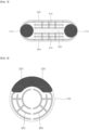
- the small-sized batteries 210 may be connected to each other in a parallel manner and may be disposed on the base 100.
- microcurrent patch As the area of the microcurrent patch increases, it is easy to create a large resistance gradient on the circuit 300. At this time, an intensive current flow is generated in the vicinity of the small-sized battery 210. To prevent this phenomenon, a microcurrent patch with a parallel structure is needed.
- a total capacity of the small-sized batteries 210 may be doubled, but the voltage thereof is the same.
- the circuit 300 connecting the small-sized batteries 210 to each other is divided into two regions.
- the glue layer 400 covers the small-sized batteries 210 and the circuit 300, while the plurality of holes 410 overlap the circuit 300 formed in a mesh structure.
- the internal resistance of the small-sized battery, the electrical resistance of the circuit, and the contact resistance between the human skin and the circuit 300 may be reduced or two small-sized batteries may be connected to each other in a series manner to increase the voltage.
- the small-sized batteries 220 may be connected to each other in the series manner and may be disposed on the base 100.
- Connecting the small-sized batteries 220 to each other in the series manner has the effect of doubling the amount of the flowing current.
- the microcurrent patch equipped with the small-sized battery 220 is attached to a thick skin layer of the human skin, effectiveness of the microcurrent may increase.
- the microcurrent patch may achieve the desired effect by arranging a number of small-sized batteries as well as controlling the shape in the desired manner.
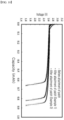
- FIG. 8 is a test result when the microcurrent patch manufactured according to the present disclosure is attached to the human body.
- the microcurrent patch had a circular shape with a diameter of 60 mm, and a small-sized battery of 1.5 V was mounted thereon.
- microamperes After attaching the microcurrent patch to a wrist, we observed the current flowing through the skin for 20 minutes using an ammeter. It is identified that 4 to 8 microamperes ( ⁇ A) flows.
- FIG. 9 shows a calculation result of an average current flowing while the patch is attached to the body by attaching the microcurrent patch to the skin and, after a certain period of time, removing the patch therefrom, and measuring the capacity of the small-sized battery and comparing the measured capacity with a capacity of the small-sized battery in the patch before the attachment.
- the patch was applied to a subject in Example 1 for 48 hours.
- the patch was applied to a subject in Example 2 for 72 hours. Then, the patch was removed therefrom. A capacity of the small-sized battery of the patch was measured.
- Example 2 It was identified that under decrease in the capacity of the small-sized battery, in Example 1, an average of 1.2 microamperes ⁇ A flowed, and in Example 2 in which the patch was attached for 72 hours, about 1 ⁇ A flowed.
- FIG. 10 identifies the effect of the voltage of the small-sized battery mounted on the microcurrent patch on the amount of the skin current by attaching a microcurrent patch in which two small-sized batteries are connected to each other in series to the body, and after a certain period of time has elapsed, removing the patch therefrom such that the small-sized battery was discharged.
- the patch attachment time duration was the same and thus 24 hours for two peoples.
- Example 1 an average of 2.1 ⁇ A flowed over 24 hours, and in Example 2, 8.8 ⁇ A flowed over 24 hours, resulting in a higher current than that in Example 1.
- Example 2 the current flowing according to the state of the body and the voltage of the battery at the time of the test had different values for different persons who participated in the test.
Landscapes
- Health & Medical Sciences (AREA)
- Life Sciences & Earth Sciences (AREA)
- Public Health (AREA)
- Veterinary Medicine (AREA)
- Radiology & Medical Imaging (AREA)
- Biomedical Technology (AREA)
- Animal Behavior & Ethology (AREA)
- General Health & Medical Sciences (AREA)
- Engineering & Computer Science (AREA)
- Nuclear Medicine, Radiotherapy & Molecular Imaging (AREA)
- Chemical & Material Sciences (AREA)
- Chemical Kinetics & Catalysis (AREA)
- General Chemical & Material Sciences (AREA)
- Biophysics (AREA)
- Heart & Thoracic Surgery (AREA)
- Electrotherapy Devices (AREA)
- Secondary Cells (AREA)
- Medicinal Preparation (AREA)
Claims (10)
- Mikrostrompflaster, umfassend:eine Basis (100) aus einem Polymerfilm;eine kleine Batterie (200), die auf der Basis angeordnet ist, um Strom zu erzeugen;eine Schaltung (300), die auf der Basis (100) angeordnet und mit der kleinen Batterie (200) verbunden ist, wobei die Schaltung (300) in zwei Bereichen angeordnet ist, so dass der Strom in der Schaltung fließt; undeine isolierende Klebstoffschicht (400), die auf der Basis (100) angeordnet und so aufgebaut ist, dass sie die kleine Batterie (200) und die Schaltung (300) bedeckt,dadurch gekennzeichnet, dass die Klebstoffschicht (400) eine Mehrzahl von Löchern (410) aufweist, die darin definiert sind und die Schaltung überlappen, wobei die Löcher so eingerichtet sind, dass sie als ein Durchgang dienen, durch den ein elektrischer Strom von der Schaltung (300) fließt.
- Pflaster nach Anspruch 1, wobei die Basis (100) eine oder mehrere Komponenten aus einer Gruppe bestehend aus Polyethylennaphthalat opposing faces (PEN) und Polyethylenterephthalat (PET) enthält.
- Pflaster nach Anspruch 1, wobei die kleine Batterie (200) mindestens zwei parallel angeordnete kleine Batterien (210) umfasst, die auf der Basis (100) angeordnet sind.
- Pflaster nach Anspruch 1, wobei die kleine Batterie (200) mindestens zwei in Reihe angeordnete kleine Batterien (220) umfasst, die auf der Basis (100) angeordnet sind.
- Pflaster nach Anspruch 1, wobei die Schaltung (300) elektrisch mit der kleinen Batterie (200) verbunden ist, wobei die Schaltung in einen Schaltungsabschnitt, der mit einem positiven Pol der kleinen Batterie verbunden ist, und einen Schaltungsteil, der mit einem negativen Pol der kleinen Batterie verbunden ist, unterteilt ist.
- Pflaster nach Anspruch 1, wobei die Schaltung (300) eine Struktur in Form eines sich überschneidenden Netzes aufweist.
- Pflaster nach einem der Ansprüche 1, 5 und 6, wobei die Schaltung (300) in einer linearen Form ausgebildet ist und eine lineare Breite der linearen Form in einem Bereich von 0,01 bis 10 mm liegt.
- Pflaster nach einem der Ansprüche 1, 5 und 6, wobei die Schaltung (300) eine oder mehrere Komponenten enthält, die aus einer Gruppe ausgewählt sind, die aus Kohlenstoff, Nickel, Silber, Aluminium, Kupfer und Gold besteht.
- Pflaster nach Anspruch 1, wobei die beiden gegenüberliegenden Flächen der Klebstoffschicht (400) jeweils aus einem Klebematerial besteht.
- Pflaster nach Anspruch 1 oder 9, wobei die Klebstoffschicht (400) aus Acrylat besteht und eine Dicke von 0,01 µm bis 1000 µm aufweist.
Applications Claiming Priority (2)
| Application Number | Priority Date | Filing Date | Title |
|---|---|---|---|
| KR1020190094371A KR102288234B1 (ko) | 2019-08-02 | 2019-08-02 | 미세전류 패치 |
| PCT/KR2020/010116 WO2021025381A1 (ko) | 2019-08-02 | 2020-07-31 | 미세전류 패치 |
Publications (4)
| Publication Number | Publication Date |
|---|---|
| EP4008394A1 EP4008394A1 (de) | 2022-06-08 |
| EP4008394A4 EP4008394A4 (de) | 2022-09-07 |
| EP4008394B1 true EP4008394B1 (de) | 2023-10-18 |
| EP4008394C0 EP4008394C0 (de) | 2023-10-18 |
Family
ID=74503195
Family Applications (1)
| Application Number | Title | Priority Date | Filing Date |
|---|---|---|---|
| EP20849880.8A Active EP4008394B1 (de) | 2019-08-02 | 2020-07-31 | Mikrostrompflaster |
Country Status (5)
| Country | Link |
|---|---|
| US (1) | US11883646B2 (de) |
| EP (1) | EP4008394B1 (de) |
| KR (1) | KR102288234B1 (de) |
| CN (1) | CN114206430B (de) |
| WO (1) | WO2021025381A1 (de) |
Families Citing this family (3)
| Publication number | Priority date | Publication date | Assignee | Title |
|---|---|---|---|---|
| CN115671535A (zh) * | 2021-07-21 | 2023-02-03 | 北京富纳特创新科技有限公司 | 理疗贴片 |
| CN115671543A (zh) * | 2021-07-21 | 2023-02-03 | 北京富纳特创新科技有限公司 | 面膜式美容仪的使用方法 |
| KR102853913B1 (ko) * | 2023-01-13 | 2025-09-01 | 김남인 | 미세전류 패치, 그의 동작 방법 및 제조 방법 |
Family Cites Families (23)
| Publication number | Priority date | Publication date | Assignee | Title |
|---|---|---|---|---|
| JP3895617B2 (ja) | 2002-03-05 | 2007-03-22 | 積水化成品工業株式会社 | 電極パッド |
| US6661161B1 (en) * | 2002-06-27 | 2003-12-09 | Andromed Inc. | Piezoelectric biological sound monitor with printed circuit board |
| KR100614118B1 (ko) * | 2006-02-24 | 2006-08-22 | 주식회사 비츠로셀 | 하이브리드 전지 |
| WO2008032291A2 (en) * | 2006-09-25 | 2008-03-20 | Philips Intellectual Property & Standards Gmbh | Multi-electrode patches for electrophysiological impedance measurements and devices for' positioning and/or alignment of electrode- patch assemblies |
| JP2008272023A (ja) * | 2007-04-25 | 2008-11-13 | Nippon Koden Corp | 生体電極包装体ユニットおよび生体電極良否判定方法 |
| US9757554B2 (en) * | 2007-08-23 | 2017-09-12 | Bioness Inc. | System for transmitting electrical current to a bodily tissue |
| US8116841B2 (en) * | 2007-09-14 | 2012-02-14 | Corventis, Inc. | Adherent device with multiple physiological sensors |
| US9808196B2 (en) * | 2010-11-17 | 2017-11-07 | Smart Solutions Technologies, S.L. | Sensors |
| KR101048506B1 (ko) * | 2011-01-31 | 2011-07-11 | 주식회사 유니온 메디칼 | 피부미용기용 필름형 프락셔널 전극패드 및 그 제조 방법 |
| US9901273B2 (en) * | 2012-07-04 | 2018-02-27 | I Medex Co., Ltd. | Bioelectrode |
| JP2016521127A (ja) | 2013-05-02 | 2016-07-21 | ボマリス イノベーションズ インコーポレイテッド | 細胞活性化のための方法及び装置 |
| KR101423241B1 (ko) | 2013-09-25 | 2014-07-24 | 김춘기 | 미세전류 생성 패치 |
| KR101592925B1 (ko) | 2013-11-29 | 2016-02-11 | 문찬곤 | 메쉬 구조를 이용한 생체신호 측정 및 전기자극 장치 |
| KR101473433B1 (ko) * | 2014-06-30 | 2014-12-18 | (주)와이브레인 | 패치 장치 |
| KR101689345B1 (ko) * | 2015-03-30 | 2016-12-26 | 조정호 | 스마트폰을 이용하는 패턴화된 전도성 탄소필름 지지체를 구비한 전류마스크팩 장치 |
| TWM505941U (zh) * | 2015-04-20 | 2015-08-01 | Wandy Rubber Ind Co Ltd | 電極熱敷貼片 |
| US10821297B2 (en) | 2016-09-30 | 2020-11-03 | Johnson & Johnson Consumer Inc. | Kit and method for topical delivery of benefits |
| KR102182169B1 (ko) | 2016-10-06 | 2020-11-24 | 엘지전자 주식회사 | 피부 케어 기기 |
| US20200008299A1 (en) * | 2016-10-21 | 2020-01-02 | Bao Tran | Flexible printed electronics |
| TWI631932B (zh) * | 2017-03-15 | 2018-08-11 | Singular Wings Medical Co., Ltd. | 生理訊號接收裝置及其製造方法 |
| KR102196717B1 (ko) * | 2017-11-15 | 2020-12-30 | 엘지전자 주식회사 | 피부 케어 기기 |
| KR102390735B1 (ko) * | 2018-09-21 | 2022-04-26 | 박찬후 | 경피약물 전달용 미세전류 발생 패치 및 이의 제조방법 |
| CN109528504B (zh) * | 2019-01-07 | 2021-06-01 | 东华大学 | 一种具有声波响应特性的微电流祛斑面膜及其制备方法 |
-
2019
- 2019-08-02 KR KR1020190094371A patent/KR102288234B1/ko active Active
-
2020
- 2020-07-31 EP EP20849880.8A patent/EP4008394B1/de active Active
- 2020-07-31 WO PCT/KR2020/010116 patent/WO2021025381A1/ko not_active Ceased
- 2020-07-31 US US17/632,341 patent/US11883646B2/en active Active
- 2020-07-31 CN CN202080056435.1A patent/CN114206430B/zh active Active
Also Published As
| Publication number | Publication date |
|---|---|
| US20220280778A1 (en) | 2022-09-08 |
| KR20210015474A (ko) | 2021-02-10 |
| CN114206430B (zh) | 2025-07-04 |
| EP4008394A1 (de) | 2022-06-08 |
| EP4008394A4 (de) | 2022-09-07 |
| EP4008394C0 (de) | 2023-10-18 |
| CN114206430A (zh) | 2022-03-18 |
| US11883646B2 (en) | 2024-01-30 |
| WO2021025381A1 (ko) | 2021-02-11 |
| KR102288234B1 (ko) | 2021-08-10 |
Similar Documents
| Publication | Publication Date | Title |
|---|---|---|
| CA1224993A (en) | Applicator for the non-invasive transcutaneous delivery of medicament | |
| CA1226777A (en) | Transdermal drug applicator | |
| US4725263A (en) | Programmable constant current source transdermal drug delivery system | |
| US11883646B2 (en) | Microcurrent patch | |
| US6129696A (en) | Transdermal drug applicator | |
| US4736752A (en) | Transcutaneous medical electrode | |
| US6653014B2 (en) | Power sources for iontophoretic drug delivery systems | |
| US5087240A (en) | Transdermal drug patch with conductive fibers | |
| US4919648A (en) | High tack drug patch | |
| US5931804A (en) | Transdermal drug applicator and electrodes therefor | |
| AU644793B2 (en) | Method and apparatus for iontophoretic drug delivery | |
| US5651768A (en) | Transdermal drug applicator and electrodes therefor | |
| EP0543241B1 (de) | Transdermaler Wirkstoff-Applikator und Elektroden hierfür | |
| EP0097436B1 (de) | Bioelektrode | |
| CA2448695A1 (en) | Apparatus for facilitating wound healing | |
| AU2002314879A1 (en) | Apparatus and methods for facilitating wound healing | |
| CA2037545C (en) | Electrotherapeutic device | |
| EP1463560A1 (de) | Reservoir-gehäuse mit einer integrierten leitenden region | |
| CN213667538U (zh) | 应用于按摩仪的电极组件和颈椎按摩仪 | |
| JPH0411726Y2 (de) | ||
| JPH0411727Y2 (de) | ||
| CN121647970A (zh) | 一种针灸治疗的头针、腕踝针的自发电电容器针灸针 | |
| CA2414398A1 (en) | Pain relief device | |
| JP2005006794A (ja) | 電流刺激型のつぼ刺激具 |
Legal Events
| Date | Code | Title | Description |
|---|---|---|---|
| STAA | Information on the status of an ep patent application or granted ep patent |
Free format text: STATUS: THE INTERNATIONAL PUBLICATION HAS BEEN MADE |
|
| PUAI | Public reference made under article 153(3) epc to a published international application that has entered the european phase |
Free format text: ORIGINAL CODE: 0009012 |
|
| STAA | Information on the status of an ep patent application or granted ep patent |
Free format text: STATUS: REQUEST FOR EXAMINATION WAS MADE |
|
| 17P | Request for examination filed |
Effective date: 20220128 |
|
| AK | Designated contracting states |
Kind code of ref document: A1 Designated state(s): AL AT BE BG CH CY CZ DE DK EE ES FI FR GB GR HR HU IE IS IT LI LT LU LV MC MK MT NL NO PL PT RO RS SE SI SK SM TR |
|
| A4 | Supplementary search report drawn up and despatched |
Effective date: 20220804 |
|
| RIC1 | Information provided on ipc code assigned before grant |
Ipc: A61N 1/02 20060101ALI20220729BHEP Ipc: A61N 1/36 20060101ALI20220729BHEP Ipc: A61N 1/04 20060101AFI20220729BHEP |
|
| DAV | Request for validation of the european patent (deleted) | ||
| DAX | Request for extension of the european patent (deleted) | ||
| RIN1 | Information on inventor provided before grant (corrected) |
Inventor name: BANG, TAE JIN Inventor name: PARK, JONG JIN Inventor name: CHOI, ARAM Inventor name: LEE, CHAE BONG Inventor name: KIM, NAM IN |
|
| GRAP | Despatch of communication of intention to grant a patent |
Free format text: ORIGINAL CODE: EPIDOSNIGR1 |
|
| STAA | Information on the status of an ep patent application or granted ep patent |
Free format text: STATUS: GRANT OF PATENT IS INTENDED |
|
| RIC1 | Information provided on ipc code assigned before grant |
Ipc: A61N 1/02 20060101ALI20230428BHEP Ipc: A61N 1/36 20060101ALI20230428BHEP Ipc: A61N 1/04 20060101AFI20230428BHEP |
|
| INTG | Intention to grant announced |
Effective date: 20230515 |
|
| GRAS | Grant fee paid |
Free format text: ORIGINAL CODE: EPIDOSNIGR3 |
|
| GRAA | (expected) grant |
Free format text: ORIGINAL CODE: 0009210 |
|
| STAA | Information on the status of an ep patent application or granted ep patent |
Free format text: STATUS: THE PATENT HAS BEEN GRANTED |
|
| AK | Designated contracting states |
Kind code of ref document: B1 Designated state(s): AL AT BE BG CH CY CZ DE DK EE ES FI FR GB GR HR HU IE IS IT LI LT LU LV MC MK MT NL NO PL PT RO RS SE SI SK SM TR |
|
| REG | Reference to a national code |
Ref country code: GB Ref legal event code: FG4D |
|
| REG | Reference to a national code |
Ref country code: CH Ref legal event code: EP |
|
| REG | Reference to a national code |
Ref country code: IE Ref legal event code: FG4D |
|
| REG | Reference to a national code |
Ref country code: DE Ref legal event code: R096 Ref document number: 602020019609 Country of ref document: DE |
|
| U01 | Request for unitary effect filed |
Effective date: 20231025 |
|
| U07 | Unitary effect registered |
Designated state(s): AT BE BG DE DK EE FI FR IT LT LU LV MT NL PT SE SI Effective date: 20231031 |
|
| PG25 | Lapsed in a contracting state [announced via postgrant information from national office to epo] |
Ref country code: GR Free format text: LAPSE BECAUSE OF FAILURE TO SUBMIT A TRANSLATION OF THE DESCRIPTION OR TO PAY THE FEE WITHIN THE PRESCRIBED TIME-LIMIT Effective date: 20240119 |
|
| PG25 | Lapsed in a contracting state [announced via postgrant information from national office to epo] |
Ref country code: IS Free format text: LAPSE BECAUSE OF FAILURE TO SUBMIT A TRANSLATION OF THE DESCRIPTION OR TO PAY THE FEE WITHIN THE PRESCRIBED TIME-LIMIT Effective date: 20240218 |
|
| PG25 | Lapsed in a contracting state [announced via postgrant information from national office to epo] |
Ref country code: ES Free format text: LAPSE BECAUSE OF FAILURE TO SUBMIT A TRANSLATION OF THE DESCRIPTION OR TO PAY THE FEE WITHIN THE PRESCRIBED TIME-LIMIT Effective date: 20231018 |
|
| PG25 | Lapsed in a contracting state [announced via postgrant information from national office to epo] |
Ref country code: IS Free format text: LAPSE BECAUSE OF FAILURE TO SUBMIT A TRANSLATION OF THE DESCRIPTION OR TO PAY THE FEE WITHIN THE PRESCRIBED TIME-LIMIT Effective date: 20240218 Ref country code: GR Free format text: LAPSE BECAUSE OF FAILURE TO SUBMIT A TRANSLATION OF THE DESCRIPTION OR TO PAY THE FEE WITHIN THE PRESCRIBED TIME-LIMIT Effective date: 20240119 Ref country code: ES Free format text: LAPSE BECAUSE OF FAILURE TO SUBMIT A TRANSLATION OF THE DESCRIPTION OR TO PAY THE FEE WITHIN THE PRESCRIBED TIME-LIMIT Effective date: 20231018 |
|
| PG25 | Lapsed in a contracting state [announced via postgrant information from national office to epo] |
Ref country code: RS Free format text: LAPSE BECAUSE OF FAILURE TO SUBMIT A TRANSLATION OF THE DESCRIPTION OR TO PAY THE FEE WITHIN THE PRESCRIBED TIME-LIMIT Effective date: 20231018 Ref country code: PL Free format text: LAPSE BECAUSE OF FAILURE TO SUBMIT A TRANSLATION OF THE DESCRIPTION OR TO PAY THE FEE WITHIN THE PRESCRIBED TIME-LIMIT Effective date: 20231018 Ref country code: NO Free format text: LAPSE BECAUSE OF FAILURE TO SUBMIT A TRANSLATION OF THE DESCRIPTION OR TO PAY THE FEE WITHIN THE PRESCRIBED TIME-LIMIT Effective date: 20240118 Ref country code: HR Free format text: LAPSE BECAUSE OF FAILURE TO SUBMIT A TRANSLATION OF THE DESCRIPTION OR TO PAY THE FEE WITHIN THE PRESCRIBED TIME-LIMIT Effective date: 20231018 |
|
| REG | Reference to a national code |
Ref country code: DE Ref legal event code: R097 Ref document number: 602020019609 Country of ref document: DE |
|
| PG25 | Lapsed in a contracting state [announced via postgrant information from national office to epo] |
Ref country code: CZ Free format text: LAPSE BECAUSE OF FAILURE TO SUBMIT A TRANSLATION OF THE DESCRIPTION OR TO PAY THE FEE WITHIN THE PRESCRIBED TIME-LIMIT Effective date: 20231018 |
|
| PG25 | Lapsed in a contracting state [announced via postgrant information from national office to epo] |
Ref country code: SK Free format text: LAPSE BECAUSE OF FAILURE TO SUBMIT A TRANSLATION OF THE DESCRIPTION OR TO PAY THE FEE WITHIN THE PRESCRIBED TIME-LIMIT Effective date: 20231018 |
|
| PG25 | Lapsed in a contracting state [announced via postgrant information from national office to epo] |
Ref country code: SM Free format text: LAPSE BECAUSE OF FAILURE TO SUBMIT A TRANSLATION OF THE DESCRIPTION OR TO PAY THE FEE WITHIN THE PRESCRIBED TIME-LIMIT Effective date: 20231018 Ref country code: SK Free format text: LAPSE BECAUSE OF FAILURE TO SUBMIT A TRANSLATION OF THE DESCRIPTION OR TO PAY THE FEE WITHIN THE PRESCRIBED TIME-LIMIT Effective date: 20231018 Ref country code: RO Free format text: LAPSE BECAUSE OF FAILURE TO SUBMIT A TRANSLATION OF THE DESCRIPTION OR TO PAY THE FEE WITHIN THE PRESCRIBED TIME-LIMIT Effective date: 20231018 Ref country code: CZ Free format text: LAPSE BECAUSE OF FAILURE TO SUBMIT A TRANSLATION OF THE DESCRIPTION OR TO PAY THE FEE WITHIN THE PRESCRIBED TIME-LIMIT Effective date: 20231018 |
|
| PLBE | No opposition filed within time limit |
Free format text: ORIGINAL CODE: 0009261 |
|
| STAA | Information on the status of an ep patent application or granted ep patent |
Free format text: STATUS: NO OPPOSITION FILED WITHIN TIME LIMIT |
|
| U20 | Renewal fee for the european patent with unitary effect paid |
Year of fee payment: 5 Effective date: 20240723 |
|
| 26N | No opposition filed |
Effective date: 20240719 |
|
| PG25 | Lapsed in a contracting state [announced via postgrant information from national office to epo] |
Ref country code: MC Free format text: LAPSE BECAUSE OF FAILURE TO SUBMIT A TRANSLATION OF THE DESCRIPTION OR TO PAY THE FEE WITHIN THE PRESCRIBED TIME-LIMIT Effective date: 20231018 |
|
| REG | Reference to a national code |
Ref country code: CH Ref legal event code: PL |
|
| GBPC | Gb: european patent ceased through non-payment of renewal fee |
Effective date: 20240731 |
|
| PG25 | Lapsed in a contracting state [announced via postgrant information from national office to epo] |
Ref country code: CH Free format text: LAPSE BECAUSE OF NON-PAYMENT OF DUE FEES Effective date: 20240731 |
|
| PG25 | Lapsed in a contracting state [announced via postgrant information from national office to epo] |
Ref country code: GB Free format text: LAPSE BECAUSE OF NON-PAYMENT OF DUE FEES Effective date: 20240731 |
|
| PG25 | Lapsed in a contracting state [announced via postgrant information from national office to epo] |
Ref country code: IE Free format text: LAPSE BECAUSE OF NON-PAYMENT OF DUE FEES Effective date: 20240731 |
|
| U20 | Renewal fee for the european patent with unitary effect paid |
Year of fee payment: 6 Effective date: 20250710 |
|
| PG25 | Lapsed in a contracting state [announced via postgrant information from national office to epo] |
Ref country code: CY Free format text: LAPSE BECAUSE OF FAILURE TO SUBMIT A TRANSLATION OF THE DESCRIPTION OR TO PAY THE FEE WITHIN THE PRESCRIBED TIME-LIMIT; INVALID AB INITIO Effective date: 20200731 |
|
| PG25 | Lapsed in a contracting state [announced via postgrant information from national office to epo] |
Ref country code: HU Free format text: LAPSE BECAUSE OF FAILURE TO SUBMIT A TRANSLATION OF THE DESCRIPTION OR TO PAY THE FEE WITHIN THE PRESCRIBED TIME-LIMIT; INVALID AB INITIO Effective date: 20200731 |