EP4008266A1 - Ultrasonic diagnostic device, ultrasonic image generation method and storage medium - Google Patents
Ultrasonic diagnostic device, ultrasonic image generation method and storage medium Download PDFInfo
- Publication number
- EP4008266A1 EP4008266A1 EP21824279.0A EP21824279A EP4008266A1 EP 4008266 A1 EP4008266 A1 EP 4008266A1 EP 21824279 A EP21824279 A EP 21824279A EP 4008266 A1 EP4008266 A1 EP 4008266A1
- Authority
- EP
- European Patent Office
- Prior art keywords
- ultrasonic
- probe
- image
- detected
- main control
- Prior art date
- Legal status (The legal status is an assumption and is not a legal conclusion. Google has not performed a legal analysis and makes no representation as to the accuracy of the status listed.)
- Pending
Links
- 238000000034 method Methods 0.000 title claims abstract description 22
- 239000000523 sample Substances 0.000 claims abstract description 238
- 238000004590 computer program Methods 0.000 claims description 6
- 230000003902 lesion Effects 0.000 abstract description 3
- 238000010586 diagram Methods 0.000 description 17
- 230000008859 change Effects 0.000 description 8
- 210000000056 organ Anatomy 0.000 description 7
- 230000008569 process Effects 0.000 description 5
- 238000004891 communication Methods 0.000 description 4
- 230000000694 effects Effects 0.000 description 3
- 238000002604 ultrasonography Methods 0.000 description 3
- 230000000712 assembly Effects 0.000 description 2
- 238000000429 assembly Methods 0.000 description 2
- 230000006870 function Effects 0.000 description 2
- 230000006872 improvement Effects 0.000 description 2
- 238000012986 modification Methods 0.000 description 2
- 230000004048 modification Effects 0.000 description 2
- 238000012014 optical coherence tomography Methods 0.000 description 2
- 230000002093 peripheral effect Effects 0.000 description 2
- 238000005070 sampling Methods 0.000 description 2
- 230000005540 biological transmission Effects 0.000 description 1
- 238000001514 detection method Methods 0.000 description 1
- 238000003745 diagnosis Methods 0.000 description 1
- 238000002405 diagnostic procedure Methods 0.000 description 1
- 201000010099 disease Diseases 0.000 description 1
- 208000037265 diseases, disorders, signs and symptoms Diseases 0.000 description 1
- 238000007689 inspection Methods 0.000 description 1
- 230000003287 optical effect Effects 0.000 description 1
- 238000012545 processing Methods 0.000 description 1
- 238000012549 training Methods 0.000 description 1
Images


Classifications
-
- A—HUMAN NECESSITIES
- A61—MEDICAL OR VETERINARY SCIENCE; HYGIENE
- A61B—DIAGNOSIS; SURGERY; IDENTIFICATION
- A61B8/00—Diagnosis using ultrasonic, sonic or infrasonic waves
- A61B8/13—Tomography
- A61B8/14—Echo-tomography
- A61B8/145—Echo-tomography characterised by scanning multiple planes
-
- A—HUMAN NECESSITIES
- A61—MEDICAL OR VETERINARY SCIENCE; HYGIENE
- A61B—DIAGNOSIS; SURGERY; IDENTIFICATION
- A61B8/00—Diagnosis using ultrasonic, sonic or infrasonic waves
- A61B8/44—Constructional features of the ultrasonic, sonic or infrasonic diagnostic device
- A61B8/4444—Constructional features of the ultrasonic, sonic or infrasonic diagnostic device related to the probe
-
- A—HUMAN NECESSITIES
- A61—MEDICAL OR VETERINARY SCIENCE; HYGIENE
- A61B—DIAGNOSIS; SURGERY; IDENTIFICATION
- A61B8/00—Diagnosis using ultrasonic, sonic or infrasonic waves
- A61B8/08—Detecting organic movements or changes, e.g. tumours, cysts, swellings
- A61B8/0833—Detecting organic movements or changes, e.g. tumours, cysts, swellings involving detecting or locating foreign bodies or organic structures
- A61B8/085—Detecting organic movements or changes, e.g. tumours, cysts, swellings involving detecting or locating foreign bodies or organic structures for locating body or organic structures, e.g. tumours, calculi, blood vessels, nodules
-
- A—HUMAN NECESSITIES
- A61—MEDICAL OR VETERINARY SCIENCE; HYGIENE
- A61B—DIAGNOSIS; SURGERY; IDENTIFICATION
- A61B8/00—Diagnosis using ultrasonic, sonic or infrasonic waves
- A61B8/42—Details of probe positioning or probe attachment to the patient
- A61B8/4245—Details of probe positioning or probe attachment to the patient involving determining the position of the probe, e.g. with respect to an external reference frame or to the patient
- A61B8/4263—Details of probe positioning or probe attachment to the patient involving determining the position of the probe, e.g. with respect to an external reference frame or to the patient using sensors not mounted on the probe, e.g. mounted on an external reference frame
-
- A—HUMAN NECESSITIES
- A61—MEDICAL OR VETERINARY SCIENCE; HYGIENE
- A61B—DIAGNOSIS; SURGERY; IDENTIFICATION
- A61B8/00—Diagnosis using ultrasonic, sonic or infrasonic waves
- A61B8/44—Constructional features of the ultrasonic, sonic or infrasonic diagnostic device
-
- A—HUMAN NECESSITIES
- A61—MEDICAL OR VETERINARY SCIENCE; HYGIENE
- A61B—DIAGNOSIS; SURGERY; IDENTIFICATION
- A61B8/00—Diagnosis using ultrasonic, sonic or infrasonic waves
- A61B8/46—Ultrasonic, sonic or infrasonic diagnostic devices with special arrangements for interfacing with the operator or the patient
- A61B8/461—Displaying means of special interest
- A61B8/463—Displaying means of special interest characterised by displaying multiple images or images and diagnostic data on one display
-
- A—HUMAN NECESSITIES
- A61—MEDICAL OR VETERINARY SCIENCE; HYGIENE
- A61B—DIAGNOSIS; SURGERY; IDENTIFICATION
- A61B8/00—Diagnosis using ultrasonic, sonic or infrasonic waves
- A61B8/46—Ultrasonic, sonic or infrasonic diagnostic devices with special arrangements for interfacing with the operator or the patient
- A61B8/461—Displaying means of special interest
- A61B8/466—Displaying means of special interest adapted to display 3D data
-
- A—HUMAN NECESSITIES
- A61—MEDICAL OR VETERINARY SCIENCE; HYGIENE
- A61B—DIAGNOSIS; SURGERY; IDENTIFICATION
- A61B8/00—Diagnosis using ultrasonic, sonic or infrasonic waves
- A61B8/48—Diagnostic techniques
- A61B8/483—Diagnostic techniques involving the acquisition of a 3D volume of data
-
- A—HUMAN NECESSITIES
- A61—MEDICAL OR VETERINARY SCIENCE; HYGIENE
- A61B—DIAGNOSIS; SURGERY; IDENTIFICATION
- A61B8/00—Diagnosis using ultrasonic, sonic or infrasonic waves
- A61B8/52—Devices using data or image processing specially adapted for diagnosis using ultrasonic, sonic or infrasonic waves
- A61B8/5207—Devices using data or image processing specially adapted for diagnosis using ultrasonic, sonic or infrasonic waves involving processing of raw data to produce diagnostic data, e.g. for generating an image
-
- A—HUMAN NECESSITIES
- A61—MEDICAL OR VETERINARY SCIENCE; HYGIENE
- A61B—DIAGNOSIS; SURGERY; IDENTIFICATION
- A61B8/00—Diagnosis using ultrasonic, sonic or infrasonic waves
- A61B8/52—Devices using data or image processing specially adapted for diagnosis using ultrasonic, sonic or infrasonic waves
- A61B8/5215—Devices using data or image processing specially adapted for diagnosis using ultrasonic, sonic or infrasonic waves involving processing of medical diagnostic data
- A61B8/5238—Devices using data or image processing specially adapted for diagnosis using ultrasonic, sonic or infrasonic waves involving processing of medical diagnostic data for combining image data of patient, e.g. merging several images from different acquisition modes into one image
- A61B8/5246—Devices using data or image processing specially adapted for diagnosis using ultrasonic, sonic or infrasonic waves involving processing of medical diagnostic data for combining image data of patient, e.g. merging several images from different acquisition modes into one image combining images from the same or different imaging techniques, e.g. color Doppler and B-mode
-
- A—HUMAN NECESSITIES
- A61—MEDICAL OR VETERINARY SCIENCE; HYGIENE
- A61B—DIAGNOSIS; SURGERY; IDENTIFICATION
- A61B8/00—Diagnosis using ultrasonic, sonic or infrasonic waves
- A61B8/54—Control of the diagnostic device
-
- A—HUMAN NECESSITIES
- A61—MEDICAL OR VETERINARY SCIENCE; HYGIENE
- A61B—DIAGNOSIS; SURGERY; IDENTIFICATION
- A61B8/00—Diagnosis using ultrasonic, sonic or infrasonic waves
- A61B8/56—Details of data transmission or power supply
-
- G—PHYSICS
- G06—COMPUTING; CALCULATING OR COUNTING
- G06T—IMAGE DATA PROCESSING OR GENERATION, IN GENERAL
- G06T7/00—Image analysis
- G06T7/0002—Inspection of images, e.g. flaw detection
-
- G—PHYSICS
- G06—COMPUTING; CALCULATING OR COUNTING
- G06T—IMAGE DATA PROCESSING OR GENERATION, IN GENERAL
- G06T7/00—Image analysis
- G06T7/50—Depth or shape recovery
- G06T7/55—Depth or shape recovery from multiple images
-
- G—PHYSICS
- G06—COMPUTING; CALCULATING OR COUNTING
- G06T—IMAGE DATA PROCESSING OR GENERATION, IN GENERAL
- G06T7/00—Image analysis
- G06T7/70—Determining position or orientation of objects or cameras
- G06T7/73—Determining position or orientation of objects or cameras using feature-based methods
-
- G—PHYSICS
- G06—COMPUTING; CALCULATING OR COUNTING
- G06T—IMAGE DATA PROCESSING OR GENERATION, IN GENERAL
- G06T2207/00—Indexing scheme for image analysis or image enhancement
- G06T2207/10—Image acquisition modality
- G06T2207/10132—Ultrasound image
-
- G—PHYSICS
- G06—COMPUTING; CALCULATING OR COUNTING
- G06T—IMAGE DATA PROCESSING OR GENERATION, IN GENERAL
- G06T2207/00—Indexing scheme for image analysis or image enhancement
- G06T2207/10—Image acquisition modality
- G06T2207/10132—Ultrasound image
- G06T2207/10136—3D ultrasound image
-
- G—PHYSICS
- G06—COMPUTING; CALCULATING OR COUNTING
- G06T—IMAGE DATA PROCESSING OR GENERATION, IN GENERAL
- G06T2207/00—Indexing scheme for image analysis or image enhancement
- G06T2207/30—Subject of image; Context of image processing
- G06T2207/30004—Biomedical image processing
-
- G—PHYSICS
- G06—COMPUTING; CALCULATING OR COUNTING
- G06T—IMAGE DATA PROCESSING OR GENERATION, IN GENERAL
- G06T2207/00—Indexing scheme for image analysis or image enhancement
- G06T2207/30—Subject of image; Context of image processing
- G06T2207/30168—Image quality inspection
Definitions
- the present disclosure relates to the technical field of ultrasonic waves, in particular to an ultrasonic diagnostic device, a method for generating an ultrasonic image, and a storage medium.
- images acquired are 2D ultrasonic slice data.
- Professional doctors perform diagnosis on the basis of the 2D ultrasonic slice image.
- Saved data is also one or several 2D ultrasonic slice images.
- a human body is a three-dimensional individual.
- a professional doctor may obtain, through techniques and experience, a 2D ultrasonic slice image that best reflects a disease
- not all doctors can find a 2D ultrasonic slice image at the most ideal position in an ultrasonic inspection operation.
- doctors working in town and village may rarely use or never use an ultrasound diagnostic device.
- 2D ultrasonic slice images that accurately reflect lesions need to be acquired, a long time training of manipulation techniques with regard to each organ is required, and it is difficult for them to acquire correct 2D ultrasonic slice images only through remote guidance. Therefore, it is difficult to realize a remote diagnostic scenario of ultrasound, and ultrasound has not been able to be promoted on a large scale.
- Some embodiments of the present disclosure aim to provide an ultrasonic diagnostic device, a method for generating an ultrasonic image, and a storage medium, so that without professional knowledge, a user may acquire an image accurately reflecting a lesion, and the difficulty in use of the ultrasonic diagnostic device is lowered.
- the embodiments of the present disclosure provide an ultrasonic diagnostic device, including: an ultrasonic probe, an acquisition assembly for a probe image, and a main control assembly connected with the ultrasonic probe and the acquisition assembly, respectively;
- the ultrasonic probe is configured to continuously scan an object to be detected located on an operating table to acquire corresponding ultrasonic images, and transmit the ultrasonic images to the main control assembly;
- the acquisition assembly is arranged at a position above the operating table; a photographing direction of the acquisition assembly faces the operating table, and a photographing range covers the operating table;
- the acquisition assembly is configured to acquire, when the ultrasonic probe is operated, a probe image containing the ultrasonic probe in real time and transmit the probe image to the main control assembly;
- the main control assembly is configured to stitch, according to the probe image, the ultrasonic images, so as to generate an ultrasonic stereo image of the object to be detected.
- the embodiments of the present disclosure further provide a method for generating an ultrasonic image, including: when it is detected that an ultrasonic probe is operated, controlling an acquisition assembly located above an operating table to acquire a probe image containing the ultrasonic probe in real time; synchronously acquiring ultrasonic images that are generated by continuously scanning an object to be detected by the ultrasonic probe; and stitching, according to the probe image, the continuous ultrasonic images, so as to generate an ultrasonic stereo image of the object to be detected.
- the embodiments of the present disclosure further provide a computer-readable storage medium which stores a computer program.
- the computer program when executed by a processor, implements the method for generating an ultrasonic image.
- the embodiments of the present disclosure have the advantages that the ultrasonic probe is configured to continuously scan the object to be detected located on the operating table, the acquisition assembly is arranged at the position above the operating table; the photographing direction of the acquisition assembly faces the operating table, and the photographing range covers the operating table; the acquisition assembly may acquire the probe image containing the ultrasonic probe in real time and transmit the acquired probe image to the main control assembly; and the main control assembly may acquire in real time the probe image and the ultrasonic images scanned by the corresponding probe and may thus stitch the continuously acquired ultrasonic images according to the probe image, so as to form the ultrasonic stereo image. Since the generated ultrasonic stereo image is a three-dimensional image displaying more details of the object to be detected, the user may read the ultrasonic stereo image as needed without professional ultrasonic operation knowledge, thus adding
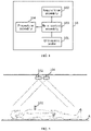
- a first embodiment of the present disclosure provides an ultrasonic diagnostic device.
- the ultrasonic diagnostic device 10 includes: an ultrasonic probe 101, an acquisition assembly 102, and a main control assembly 103.
- the structural block diagram of the ultrasonic diagnostic device is shown in FIG. 1 .
- the acquisition assembly 102 and the ultrasonic probe are connected with the main control assembly.
- the ultrasonic probe 101 is configured to continuously scan an object to be detected 30 located on an operating table 20 to acquire corresponding ultrasonic images, and transmit the ultrasonic images to the main control assembly 103;
- the acquisition assembly 102 is arranged at a position above the operating table 20; a photographing direction of the acquisition assembly 102 faces the operating table 20, and a photographing range covers the operating table 20;
- the acquisition assembly 102 is configured to acquire, when the ultrasonic probe 101 is operated, a probe image containing the ultrasonic probe 101 in real time and transmit the probe image to the main control assembly 103;
- the main control assembly 103 is configured to stitch, according to the probe image, the ultrasonic images, so as to generate an ultrasonic stereo image of the object to be detected.
- the ultrasonic probe is configured to continuously scan the object to be detected located on the operating table
- the acquisition assembly is arranged at the position above the operating table; the photographing direction of the acquisition assembly faces the operating table, and the photographing range covers the operating table;
- the acquisition assembly may acquire the probe image containing the ultrasonic probe in real time and transmit the acquired probe image to the main control assembly;
- the main control assembly may acquire in real time the probe image and the ultrasonic images scanned by the corresponding probe and may thus stitch the continuously acquired ultrasonic images according to the probe image, so as to form the ultrasonic stereo image. Since the generated ultrasonic stereo image is a three-dimensional image displaying more details of the object to be detected, the user may read the ultrasonic stereo image as needed without professional ultrasonic operation knowledge, thus adding the usage scenario of the ultrasonic diagnostic device.
- a second embodiment of the present disclosure relates to an ultrasonic diagnostic device.
- the present embodiment is a specific introduction of the ultrasonic diagnostic device in the first embodiment. Disposing positions of all assemblies in the ultrasonic diagnostic device are introduced below in combination with FIG. 2 .
- the operating table A is configured to assist the object to be detected in keeping a steady state.
- the operating table A may be a sickbed, or the like.
- the operating table A with the object to be detected may be parallel to a horizontal plane.
- the object to be detected may lie down on the operating table; the ultrasonic probe connected with the main control assembly 103 scans the object to be detected to obtain an ultrasonic image.
- the ultrasonic probe 101 may include a two-dimensional probe or a three-dimensional probe.
- the acquisition assembly 102 is arranged at the position right above the operating table A.
- the acquisition assembly 102 is configured to photograph the ultrasonic probe in real time and may include at least one camera.
- the camera may be a 2D camera or a 3D camera.
- the photographing direction of the acquisition assembly 102 faces the operating table A, and the photographing range covers the whole operating table, so as to ensure that the acquisition assembly 102 is able to photograph the camera no matter how the ultrasonic probe 101 moves in the scanning process.
- the ultrasonic probe 101 and the acquisition assembly 102 are in communication connection with the main control assembly 103.
- the connection may be wireless connection or wired connection.
- the main control assembly 103 is not shown in FIG. 2 .
- the main control assembly 103 may be arranged above the operating table A or may be arranged at other positions.
- the main control assembly 103 may include a processor, such as a computer device.
- An operating process of the ultrasonic diagnostic device is as follows: when it is detected that the ultrasonic probe is operated, the main control assembly 103 controls the acquisition assembly to start to take images in real time; the ultrasonic probe 101 scans the obtained ultrasonic images and transmits them to the main control assembly in real time; and similarly, the acquisition assembly 102 transmits the probe image that is taken in real time to the main control assembly 103.
- the main control assembly 103 may synchronize the operation of the acquisition assembly 102 with the operation of the ultrasonic probe 101.
- the ultrasonic probe 101 may send, to the main control assembly 103, prompt information indicating that the ultrasonic probe 101 is started.
- the main control assembly 103 may start the acquisition assembly 102 to perform real-time photographing after acquiring the prompt information.
- a time tag that represents scanning time may be added, according to the chronological order of the scanning time, for each of the ultrasonic images.
- a time tag that represents photographing time may be added for each probe image. The corresponding probe image in the ultrasonic image at the same time may be searched through the time tag.
- the main control assembly 103 is specifically configured to: acquire a probe position and a probe angle of the ultrasonic probe in a preset three-dimensional spatial coordinate system according to the received probe image; place the ultrasonic image scanned by the current ultrasonic probe 101 on the probe position according to the probe angle in the three-dimensional spatial coordinate system; and if it is detected that the ultrasonic probe 101 completes the scanning, stitch each of the ultrasonic images located in the three-dimensional spatial coordinate system, so as to generate the ultrasonic stereo image.
- the three-dimensional spatial coordinate system may be preset. Any position in the three-dimensional spatial coordinate system may be taken as a corresponding probe position of the ultrasonic probe 101 in the three-dimensional spatial coordinate system, and any angle may also be taken as an initial probe angle in the preset three-dimensional spatial coordinate system.
- Way I the main control assembly 103 may identify a position, in the probe image, of the ultrasonic probe 101 in the probe image after acquiring the probe image. Since the photographing direction of the acquisition assembly 102 is fixed, the camera in the acquisition assembly 102 is stationary, and the probe position of the current ultrasonic probe in the three-dimensional spatial coordinate system may be acquired according to the corresponding position of the ultrasonic probe 101 in the three-dimensional spatial coordinate system when the ultrasonic probe is started. The way to acquire the probe angle is similar.
- the initial probe position is set as (x0, y0, z0) in the three-dimensional spatial coordinate system, and the probe angle at the initial time t0 is set as ( ⁇ 0, ⁇ 0, ⁇ 0); the ultrasonic probe in the probe image corresponding to t1 is identified, and the position of the ultrasonic probe in the probe image is acquired; the probe position of the probe at t1 may be determined according to a correspondence relationship between the position of the ultrasonic probe at the initial time t0 in the image and the initial probe position (x0, y0, z0); similarly, the probe angle of the ultrasonic probe at t1 may be determined according to a correspondence relationship between the angle of the ultrasonic probe at the initial time in the probe image relative to the object to be detected and the initial probe angle ( ⁇ 0, ⁇ 0, ⁇ 0).
- the acquired probe position is an absolute position
- the probe angle is an absolute angle.
- a relative position change of the ultrasonic probe may be acquired by means of a difference between the probe image at the current time and the probe image at the previous time, and the probe position of the ultrasonic probe at the current time may be determined according to the relative position change and absolute coordinates of the ultrasonic probe at the previous time.
- an angle change of the ultrasonic probe may also be acquired, and the probe angle of the ultrasonic probe at the current time is determined according to the relative angle change and the probe angle of the ultrasonic probe at the previous time.
- the ultrasonic image may be placed on the probe position according to the probe angle.
- the ultrasonic probe continuously scans the object to be detected; each of the ultrasonic images is placed, in accordance with the probe position of the ultrasonic probe, in the three-dimensional spatial coordinate system; and after it is detected that the ultrasonic probe completes the scanning, each of the ultrasonic images in the three-dimensional spatial coordinate system may be stitched to generate the ultrasonic stereo image.
- the ultrasonic probe may scan a human leg according to a moving direction B as shown in FIG. 3 .
- the human leg is an object to be detected.
- the ultrasonic probe is a 2D probe
- each of the ultrasonic images is placed in the three-dimensional spatial coordinate system according to the probe position of the ultrasonic probe.
- an ultrasonic image arrangement diagram as shown in FIG. 4 is formed.
- Each of the ultrasonic images is an optical coherence tomography.
- a section interval will also be different according to changes in a moving speed of the ultrasonic probe 101.
- the ultrasonic probe usually has a high sampling frequency, so an ultrasonic image arrangement diagram with a very small actual interval may be formed.
- the ultrasonic images arranged as shown in FIG. 4 are stitched to form the ultrasonic stereo image as shown in FIG. 6 . If the moving speed of the ultrasonic probe is lower, a three-dimensional point cloud obtained is denser, and the formed ultrasonic stereo image is more accurate.
- each frame of ultrasonic image has a certain width
- each scanned frame of ultrasonic image is a cubic slice with a certain width and is one three-dimensional optical coherence tomography of the leg, which is in a form as shown in FIG. 5 . Since width information is acquired at each time, if the ultrasonic probe 101 moves slowly, there will be an image overlap part in two adjacent sampling operations, and the data of the overlap part shall be identical. Therefore, after each of the ultrasonic images is stitched, one stereo semipermeable dense point cloud graph is obtained, thus forming three-dimensional point cloud data and obtaining an ultrasonic stereo image of the leg, as shown in FIG. 6 .
- the ultrasonic diagnostic device 10 further includes: a display connected with the main control assembly.
- the display is configured to display the ultrasonic stereo image.
- the main control assembly 103 is further configured to slice, when an instruction that instructs a specified section to be display is detected, the ultrasonic stereo image, generate an ultrasonic image of the specified section, and transmit the ultrasonic image to the display.
- the display may be an ordinary display, or may be a holographic image display.
- the display displays the ultrasonic stereo image. If the user needs to observe the ultrasonic image of the specified section, the user may input information of the specified section through an input device.
- the main control assembly slices the ultrasonic stereo image after receiving the instruction, generates the ultrasonic image of the specified section, and transmits the ultrasonic image to the display.
- the display displays the ultrasonic image of the specified section.
- the specified section is a section 1 and a section 2 as shown in FIG. 7 .
- a third embodiment of the present disclosure relates to an ultrasonic diagnostic device.
- the present embodiment is an improvement of the first embodiment or the second embodiment.
- a main improvement is that the ultrasonic diagnostic device in this embodiment further includes a projection assembly 104.
- the structural block diagram of the ultrasonic diagnostic device is as shown in FIG. 8 . Disposing positions of all assemblies in the ultrasonic diagnostic device are introduced below in combination with FIG. 9 .
- the projection assembly 104 is arranged at a position above the operating table A.
- the projection assembly 104 is connected with the acquisition assembly 102 and the main control assembly 103, respectively.
- the position of the projection assembly 104 may be close to the acquisition assembly 102.
- the projection assembly 104 may be ordinary projection device.
- the projection assembly 104 may be connected to the main control assembly 103 in a wireless or wired manner.
- the acquisition assembly 102 is further configured to photograph the object to be detected, acquire a first image, and transmit the first image to the main control assembly 103.
- the main control assembly 103 generates, according to the first image, a specified scanning region image containing a specified scanning region of the object to be detected; and the projection assembly 104 projects the specified scanning region image on the object to be detected.
- the specified scanning region may be preset in the main control assembly 103.
- the specified scanning region may be an organ to be detected.
- a sensor may be arranged on the operating table A. The sensor is configured to detect whether there is an object to be detected on the operating table A and send a detection result to the main control assembly 103. After receiving indication information for indicating that there is an object to be detected on the operating table A, the main control assembly 103 starts the acquisition assembly 102 to photograph the object to be detected, and the first image is transmitted to the main control assembly 103.
- the main control assembly 103 generates, according to a position, in the image, of the object to be detected in the first image and the preset organ to be detected or a position to be detected, the specified scanning region image containing the specified scanning region of the object to be detected.
- the main control assembly 103 sends the specified scanning region image to the projection assembly 104.
- the projection assembly 104 projects the specified scanning region image on the object to be detected.
- the projection effect of the projection assembly is shown in FIG. 10 .
- the square dotted line box is the specified scanning region image.
- main control assembly 103 may further set projection parameters of the projection assembly 104 according to the specified region image and the position of the object to be detected in the first image, so that corresponding specified scanning region images may be projected in case of different object to be detected.
- the specified scanning region may also be an organ to be detected.
- the specified scanning region image may be an organ image corresponding to the object to be detected, and the organ image may be projected at the position of the organ to be detected of the object to be detected.
- the main control assembly 103 is further configured to: generate, according to the specified scanning region, a scanning path image for indicating movement of the ultrasonic probe and send the scanning path image to the projection assembly 104; and the projection assembly 104 is further configured to project the scanning path image on the object to be detected.
- the projected scanning path may be shown by the arrow in the dotted line box in FIG. 11 .
- the user may control the ultrasonic probe to scan the specified scanning region according to the scanning path.
- the main control assembly 103 is further configured to: after it is detected that the ultrasonic probe 101 completes the scanning, if it is detected that an overlap part of a coverage region formed by all the ultrasonic images and the specified scanning region is smaller than the specified scanning region, output first error indication information; and/or, if it is detected that the ultrasonic images include a fuzzy image, output second error indication information.
- the ultrasonic probe 101 if it is detected that the ultrasonic probe 101 leaves a surface of the object to be detected, it is determined that the ultrasonic probe completes the scanning. Before the stitching of each of the ultrasonic images, it may be detected whether the overlap part between the coverage region formed by all the ultrasonic images and the specified scanning region is smaller than the specified scanning region; if yes, it is indicated that there is a region not scanned, and the first error indication information may be output. In addition, it may also be detected whether the acquired ultrasonic images include the fuzzy image; if yes, the second error indication information is output.
- the first error indication information includes an image of a missing region, and a sum of the missing region and the overlap part is greater than or equal to the specified scanning region;
- the second error indication information includes a photographing position for photographing the fuzzy image;
- the projection assembly is further configured to project the image of the missing region on the object to be detected; or, the projection assembly is further configured to project an image that represents the photographing position on the object to be detected.
- the user may re-scan the missing region or the photographing position according to the image projected by the projection assembly, thereby obtaining an accurate ultrasonic image and improving the accuracy of the subsequently generated ultrasonic stereo image.
- the ultrasonic image arrangement diagram obtained by arrangement according to the probe angle, even if there is tilting, such as the ultrasonic image E and the ultrasonic image F as shown in FIG. 12 , and if the scanning frequency is greater than a preset frequency, the tilted ultrasonic image may not be processed. If the scanning frequency is less than the preset frequency, it may instruct the scanning frequency to be increased to re-scan the specified scanning region.
- a fourth embodiment of the present disclosure relates to a method for generating an ultrasonic image, which is applied to an ultrasonic diagnostic device. The process is shown in FIG. 13 .
- step 401 when it is detected that an ultrasonic probe is operated, an acquisition assembly located above an operating table is controlled to acquire a probe image containing the ultrasonic probe in real time.
- the acquisition assembly is arranged at the position above the operating table.
- the acquisition assembly may be a camera.
- a lens of the camera faces the operating table, and a photographing view of the camera covers the operating table.
- the acquisition assembly and the ultrasonic probe are in communication connection with the main control assembly.
- the communication connection may be wireless connection or wired connection.
- the ultrasonic probe When the ultrasonic probe contacts a surface of the object to be detected, it triggers the ultrasonic probe to be operated. When it is detected that the ultrasonic probe is operated, the acquisition assembly located above the operating table is controlled to acquire the probe image containing the ultrasonic probe in real time.
- step 402 ultrasonic images obtained by continuously scanning the object to be detected by the ultrasonic probe are continuously acquired.
- the ultrasonic image scanned by the ultrasonic probe at the corresponding time is synchronously acquired.
- the continuous ultrasonic images are stitched according to the pose data, so as to generate an ultrasonic stereo image of the object to be detected.
- a probe position and a probe angle of the ultrasonic probe in a preset three-dimensional spatial coordinate system are acquired according to the received probe image; the ultrasonic image scanned by the current ultrasonic probe is placed on the probe position according to the probe angle in the three-dimensional spatial coordinate system; and if it is detected that the ultrasonic probe completes the scanning, each of the ultrasonic images located in the three-dimensional spatial coordinate system is stitched, so as to generate the ultrasonic stereo image.
- the three-dimensional spatial coordinate system may be preset. Any position in the three-dimensional spatial coordinate system may be taken as an initial probe position in the three-dimensional spatial coordinate system when the ultrasonic probe is started, and any angle may also be taken as an initial probe angle in the preset three-dimensional spatial coordinate system.
- Way I the main control assembly 103 may identify a position, in the probe image, of the ultrasonic probe 101 in the probe image after acquiring the probe image. Since the photographing direction of the acquisition assembly 102 is fixed, the camera in the acquisition assembly 102 is stationary, and the probe position of the current ultrasonic probe in the three-dimensional spatial coordinate system may be acquired according to the corresponding position of the ultrasonic probe 101 in the three-dimensional spatial coordinate system when the ultrasonic probe is started. The way to acquire the probe angle is similar.
- the initial probe position is set as (x0, y0, z0) in the three-dimensional spatial coordinate system, and the probe angle at the initial time t0 is set as ( ⁇ 0, ⁇ 0, ⁇ 0); the ultrasonic probe in the probe image corresponding to t1 is identified, and the position of the ultrasonic probe in the probe image is acquired; the probe position of the probe at t1 may be determined according to a correspondence relationship between the position of the ultrasonic probe at the initial time t0 in the image and the initial probe position (x0, y0, z0); similarly, the probe angle of the ultrasonic probe at t1 may be determined according to a correspondence relationship between the angle of the ultrasonic probe at the initial time in the probe image relative to the object to be detected and the initial probe angle ( ⁇ 0, ⁇ 0, ⁇ 0).
- the acquired probe position is an absolute position
- the probe angle is an absolute angle.
- a relative position change of the ultrasonic probe may be acquired by means of a difference between the probe image at the current time and the probe image at the previous time, and the probe position of the ultrasonic probe at the current time may be determined according to the relative position change and absolute coordinates of the ultrasonic probe at the previous time.
- an angle change of the ultrasonic probe may also be acquired, and the probe angle of the ultrasonic probe at the current time is determined according to the relative angle change and the probe angle of the ultrasonic probe at the previous time.
- the ultrasonic image may be placed on the probe position in accordance with the probe angle.
- the ultrasonic probe continuously scans the object to be detected; each of the ultrasonic images is placed, in accordance with the probe position of the ultrasonic probe, in the three-dimensional spatial coordinate system; and after it is detected that the ultrasonic probe completes the scanning, each of the ultrasonic images in the three-dimensional spatial coordinate system may be stitched to generate the ultrasonic stereo image.
- the main control assembly in the ultrasonic diagnostic device may include a memory and a processor.
- the memory is in communication connection with the at least one processor.
- the memory stores an instruction that may be executed by the at least one processor.
- the instruction is executed by the at least one processor to cause the at least one processor to be able to implement the above method for generating an ultrasonic image.
- the memory and the processor are connected by a bus.
- the bus may include any number of interconnected buses and bridges.
- the bus links one or more processors with various circuits of the memory together.
- the bus may also link various other circuits such as peripherals, voltage regulators and power management circuits, which are well known in the art and, therefore, will not be further described herein.
- a bus interface provides an interface between the bus and a transceiver.
- the transceiver may be one element or a plurality of elements, such as a plurality of receivers and transmitters to provide units for communicating with various other devices on a transmission medium.
- Data processed by the processor is transmitted on a wireless medium through an antenna, and further, the antenna also receives the data and transmits the data to the processor.
- the processor is responsible for managing the bus and performing general processing, and can also provide various functions including timing, peripheral interfaces, voltage regulation and power management, and other control functions.
- the memory can be used to store data used by the processor when performing operations.
- a fifth embodiment of the present disclosure relates to a computer-readable storage medium which stores a computer program.
- the computer program when executed by a processor, implements the method for generating an ultrasonic image.
- This program is stored in a storage medium and includes a number of instructions configured to enable one device (which may be a single-chip microcomputer, a chip, and the like) or a processor to execute all or part of the steps of the methods described in the various embodiments of the present disclosure.
- the aforementioned storage media include: a USB flash disk, a mobile hard disk, a read-only memory (ROM), a random access memory (RAM), a magnetic disk or an optical disk, and other media that can store program codes.
Landscapes
- Health & Medical Sciences (AREA)
- Life Sciences & Earth Sciences (AREA)
- Engineering & Computer Science (AREA)
- Physics & Mathematics (AREA)
- Surgery (AREA)
- Public Health (AREA)
- Radiology & Medical Imaging (AREA)
- Nuclear Medicine, Radiotherapy & Molecular Imaging (AREA)
- Biomedical Technology (AREA)
- Heart & Thoracic Surgery (AREA)
- Medical Informatics (AREA)
- Molecular Biology (AREA)
- Biophysics (AREA)
- Animal Behavior & Ethology (AREA)
- General Health & Medical Sciences (AREA)
- Pathology (AREA)
- Veterinary Medicine (AREA)
- Computer Vision & Pattern Recognition (AREA)
- General Physics & Mathematics (AREA)
- Theoretical Computer Science (AREA)
- Computer Graphics (AREA)
- General Engineering & Computer Science (AREA)
- Vascular Medicine (AREA)
- Computer Networks & Wireless Communication (AREA)
- Quality & Reliability (AREA)
- Ultra Sonic Daignosis Equipment (AREA)
Abstract
Description
- The present disclosure relates to the technical field of ultrasonic waves, in particular to an ultrasonic diagnostic device, a method for generating an ultrasonic image, and a storage medium.
- For current ultrasonic diagnostic device, images acquired are 2D ultrasonic slice data. Professional doctors perform diagnosis on the basis of the 2D ultrasonic slice image. Saved data is also one or several 2D ultrasonic slice images.
- However, a human body is a three-dimensional individual. Although a professional doctor may obtain, through techniques and experience, a 2D ultrasonic slice image that best reflects a disease, not all doctors can find a 2D ultrasonic slice image at the most ideal position in an ultrasonic inspection operation. For example, doctors working in town and village may rarely use or never use an ultrasound diagnostic device. If 2D ultrasonic slice images that accurately reflect lesions need to be acquired, a long time training of manipulation techniques with regard to each organ is required, and it is difficult for them to acquire correct 2D ultrasonic slice images only through remote guidance. Therefore, it is difficult to realize a remote diagnostic scenario of ultrasound, and ultrasound has not been able to be promoted on a large scale.
- Some embodiments of the present disclosure aim to provide an ultrasonic diagnostic device, a method for generating an ultrasonic image, and a storage medium, so that without professional knowledge, a user may acquire an image accurately reflecting a lesion, and the difficulty in use of the ultrasonic diagnostic device is lowered.
- The embodiments of the present disclosure provide an ultrasonic diagnostic device, including: an ultrasonic probe, an acquisition assembly for a probe image, and a main control assembly connected with the ultrasonic probe and the acquisition assembly, respectively; the ultrasonic probe is configured to continuously scan an object to be detected located on an operating table to acquire corresponding ultrasonic images, and transmit the ultrasonic images to the main control assembly; the acquisition assembly is arranged at a position above the operating table; a photographing direction of the acquisition assembly faces the operating table, and a photographing range covers the operating table; the acquisition assembly is configured to acquire, when the ultrasonic probe is operated, a probe image containing the ultrasonic probe in real time and transmit the probe image to the main control assembly; and the main control assembly is configured to stitch, according to the probe image, the ultrasonic images, so as to generate an ultrasonic stereo image of the object to be detected.
- The embodiments of the present disclosure further provide a method for generating an ultrasonic image, including: when it is detected that an ultrasonic probe is operated, controlling an acquisition assembly located above an operating table to acquire a probe image containing the ultrasonic probe in real time; synchronously acquiring ultrasonic images that are generated by continuously scanning an object to be detected by the ultrasonic probe; and stitching, according to the probe image, the continuous ultrasonic images, so as to generate an ultrasonic stereo image of the object to be detected.
- The embodiments of the present disclosure further provide a computer-readable storage medium which stores a computer program. The computer program, when executed by a processor, implements the method for generating an ultrasonic image. Compared with the existing art, the embodiments of the present disclosure have the advantages that the ultrasonic probe is configured to continuously scan the object to be detected located on the operating table, the acquisition assembly is arranged at the position above the operating table; the photographing direction of the acquisition assembly faces the operating table, and the photographing range covers the operating table; the acquisition assembly may acquire the probe image containing the ultrasonic probe in real time and transmit the acquired probe image to the main control assembly; and the main control assembly may acquire in real time the probe image and the ultrasonic images scanned by the corresponding probe and may thus stitch the continuously acquired ultrasonic images according to the probe image, so as to form the ultrasonic stereo image. Since the generated ultrasonic stereo image is a three-dimensional image displaying more details of the object to be detected, the user may read the ultrasonic stereo image as needed without professional ultrasonic operation knowledge, thus adding the usage scenario of the ultrasonic diagnostic device.
- One or more embodiments are exemplified by the corresponding accompanying drawings. These exemplified descriptions do not constitute a limitation to the embodiments. Elements with the same reference numerals in the accompanying drawings are shown as similar elements. The drawings in the accompanying drawings do not constitute scaling restrictions unless otherwise stated.
-
FIG. 1 is a structural block diagram of an ultrasonic diagnostic device according to a first embodiment of the present disclosure; -
FIG. 2 is a schematic diagram of an ultrasonic diagnostic device according to a second embodiment of the present disclosure; -
FIG. 3 is a schematic diagram of a moving direction of an ultrasonic probe according to a second embodiment of the present disclosure; -
FIG. 4 is a schematic diagram of arrangement of ultrasonic images according to a second embodiment of the present disclosure; -
FIG. 5 is another schematic diagram of arrangement of ultrasonic images according to a second embodiment of the present disclosure; -
FIG. 6 is a schematic diagram of an ultrasonic stereo image according to a second embodiment of the present disclosure; -
FIG. 7 is a schematic diagram of an ultrasonic image of a specified section according to a second embodiment of the present disclosure; -
FIG. 8 is a structural block diagram of an ultrasonic diagnostic device according to a third embodiment of the present disclosure; -
FIG. 9 is a schematic diagram of an ultrasonic diagnostic device according to a third embodiment of the present disclosure; -
FIG. 10 is a schematic diagram of a projection effect of an ultrasonic diagnostic device according to a third embodiment of the present disclosure; -
FIG. 11 is a schematic effect diagram of a projection scanning path of an ultrasonic diagnostic device according to a third embodiment of the present disclosure; -
FIG. 12 is a schematic diagram of arrangement of ultrasonic images according to a third embodiment of the present disclosure; and -
FIG. 13 is a flowchart of a method for generating an ultrasonic image according to a fourth embodiment of the present disclosure. - In order to make the objectives, technical solutions and advantages of the present disclosure clearer, some embodiments of the present disclosure is further described below in detail with reference to accompanying drawings and embodiments. Those of ordinary skill in the art can understand that in the various embodiments, many technical details are presented in order to make the present disclosure better understood by readers. However, the technical solutions claimed in the present disclosure can also be implemented without these technical details and various changes and modifications based on the embodiments. All the following embodiments are divided for the convenience of description and shall not constitute any restriction on the specific implementation modes of the present disclosure. All the embodiments can be combined and referenced with each other with no conflicts.
- A first embodiment of the present disclosure provides an ultrasonic diagnostic device. The ultrasonic
diagnostic device 10 includes: anultrasonic probe 101, anacquisition assembly 102, and amain control assembly 103. The structural block diagram of the ultrasonic diagnostic device is shown inFIG. 1 . Theacquisition assembly 102 and the ultrasonic probe are connected with the main control assembly. Theultrasonic probe 101 is configured to continuously scan an object to be detected 30 located on an operating table 20 to acquire corresponding ultrasonic images, and transmit the ultrasonic images to themain control assembly 103; theacquisition assembly 102 is arranged at a position above the operating table 20; a photographing direction of theacquisition assembly 102 faces the operating table 20, and a photographing range covers the operating table 20; theacquisition assembly 102 is configured to acquire, when theultrasonic probe 101 is operated, a probe image containing theultrasonic probe 101 in real time and transmit the probe image to themain control assembly 103; and themain control assembly 103 is configured to stitch, according to the probe image, the ultrasonic images, so as to generate an ultrasonic stereo image of the object to be detected. - In the embodiments of the present disclosure, the ultrasonic probe is configured to continuously scan the object to be detected located on the operating table, the acquisition assembly is arranged at the position above the operating table; the photographing direction of the acquisition assembly faces the operating table, and the photographing range covers the operating table; the acquisition assembly may acquire the probe image containing the ultrasonic probe in real time and transmit the acquired probe image to the main control assembly; and the main control assembly may acquire in real time the probe image and the ultrasonic images scanned by the corresponding probe and may thus stitch the continuously acquired ultrasonic images according to the probe image, so as to form the ultrasonic stereo image. Since the generated ultrasonic stereo image is a three-dimensional image displaying more details of the object to be detected, the user may read the ultrasonic stereo image as needed without professional ultrasonic operation knowledge, thus adding the usage scenario of the ultrasonic diagnostic device.
- A second embodiment of the present disclosure relates to an ultrasonic diagnostic device. The present embodiment is a specific introduction of the ultrasonic diagnostic device in the first embodiment. Disposing positions of all assemblies in the ultrasonic diagnostic device are introduced below in combination with
FIG. 2 . - As shown in
FIG. 2 , the operating table A is configured to assist the object to be detected in keeping a steady state. For example, the operating table A may be a sickbed, or the like. The operating table A with the object to be detected may be parallel to a horizontal plane. In an ultrasonic diagnostic process, the object to be detected may lie down on the operating table; the ultrasonic probe connected with themain control assembly 103 scans the object to be detected to obtain an ultrasonic image. Theultrasonic probe 101 may include a two-dimensional probe or a three-dimensional probe. - The
acquisition assembly 102 is arranged at the position right above the operating table A. Theacquisition assembly 102 is configured to photograph the ultrasonic probe in real time and may include at least one camera. The camera may be a 2D camera or a 3D camera. The photographing direction of theacquisition assembly 102 faces the operating table A, and the photographing range covers the whole operating table, so as to ensure that theacquisition assembly 102 is able to photograph the camera no matter how theultrasonic probe 101 moves in the scanning process. In particular, theultrasonic probe 101 and theacquisition assembly 102 are in communication connection with themain control assembly 103. The connection may be wireless connection or wired connection. Themain control assembly 103 is not shown inFIG. 2 . Themain control assembly 103 may be arranged above the operating table A or may be arranged at other positions. Themain control assembly 103 may include a processor, such as a computer device. - An operating process of the ultrasonic diagnostic device is as follows: when it is detected that the ultrasonic probe is operated, the
main control assembly 103 controls the acquisition assembly to start to take images in real time; theultrasonic probe 101 scans the obtained ultrasonic images and transmits them to the main control assembly in real time; and similarly, theacquisition assembly 102 transmits the probe image that is taken in real time to themain control assembly 103. Themain control assembly 103 may synchronize the operation of theacquisition assembly 102 with the operation of theultrasonic probe 101. - After touching the object to be detected, the
ultrasonic probe 101 may send, to themain control assembly 103, prompt information indicating that theultrasonic probe 101 is started. Themain control assembly 103 may start theacquisition assembly 102 to perform real-time photographing after acquiring the prompt information. - It should be noted that a time tag that represents scanning time may be added, according to the chronological order of the scanning time, for each of the ultrasonic images. Similarly, a time tag that represents photographing time may be added for each probe image. The corresponding probe image in the ultrasonic image at the same time may be searched through the time tag.
- In one example, the
main control assembly 103 is specifically configured to: acquire a probe position and a probe angle of the ultrasonic probe in a preset three-dimensional spatial coordinate system according to the received probe image; place the ultrasonic image scanned by the currentultrasonic probe 101 on the probe position according to the probe angle in the three-dimensional spatial coordinate system; and if it is detected that theultrasonic probe 101 completes the scanning, stitch each of the ultrasonic images located in the three-dimensional spatial coordinate system, so as to generate the ultrasonic stereo image. - Specifically, the three-dimensional spatial coordinate system may be preset. Any position in the three-dimensional spatial coordinate system may be taken as a corresponding probe position of the
ultrasonic probe 101 in the three-dimensional spatial coordinate system, and any angle may also be taken as an initial probe angle in the preset three-dimensional spatial coordinate system. - There are various ways to acquire the probe position and the probe angle. Two ways to acquire the probe position and the probe angle are introduced below:
Way I: themain control assembly 103 may identify a position, in the probe image, of theultrasonic probe 101 in the probe image after acquiring the probe image. Since the photographing direction of theacquisition assembly 102 is fixed, the camera in theacquisition assembly 102 is stationary, and the probe position of the current ultrasonic probe in the three-dimensional spatial coordinate system may be acquired according to the corresponding position of theultrasonic probe 101 in the three-dimensional spatial coordinate system when the ultrasonic probe is started. The way to acquire the probe angle is similar. - For example, the initial probe position is set as (x0, y0, z0) in the three-dimensional spatial coordinate system, and the probe angle at the initial time t0 is set as (α0, β0, γ0); the ultrasonic probe in the probe image corresponding to t1 is identified, and the position of the ultrasonic probe in the probe image is acquired; the probe position of the probe at t1 may be determined according to a correspondence relationship between the position of the ultrasonic probe at the initial time t0 in the image and the initial probe position (x0, y0, z0); similarly, the probe angle of the ultrasonic probe at t1 may be determined according to a correspondence relationship between the angle of the ultrasonic probe at the initial time in the probe image relative to the object to be detected and the initial probe angle (α0, β0, γ0). The acquired probe position is an absolute position, and the probe angle is an absolute angle.
- Way II: A relative position change of the ultrasonic probe may be acquired by means of a difference between the probe image at the current time and the probe image at the previous time, and the probe position of the ultrasonic probe at the current time may be determined according to the relative position change and absolute coordinates of the ultrasonic probe at the previous time. Similarly, an angle change of the ultrasonic probe may also be acquired, and the probe angle of the ultrasonic probe at the current time is determined according to the relative angle change and the probe angle of the ultrasonic probe at the previous time.
- After the probe position and the probe angle of the ultrasonic probe are acquired, the ultrasonic image may be placed on the probe position according to the probe angle.
- The ultrasonic probe continuously scans the object to be detected; each of the ultrasonic images is placed, in accordance with the probe position of the ultrasonic probe, in the three-dimensional spatial coordinate system; and after it is detected that the ultrasonic probe completes the scanning, each of the ultrasonic images in the three-dimensional spatial coordinate system may be stitched to generate the ultrasonic stereo image.
- For example, the ultrasonic probe may scan a human leg according to a moving direction B as shown in
FIG. 3 . The human leg is an object to be detected. If the ultrasonic probe is a 2D probe, each of the ultrasonic images is placed in the three-dimensional spatial coordinate system according to the probe position of the ultrasonic probe. After it is detected that the ultrasonic probe completes the scanning, an ultrasonic image arrangement diagram as shown inFIG. 4 is formed. Each of the ultrasonic images is an optical coherence tomography. A section interval will also be different according to changes in a moving speed of theultrasonic probe 101. The ultrasonic probe usually has a high sampling frequency, so an ultrasonic image arrangement diagram with a very small actual interval may be formed. The ultrasonic images arranged as shown inFIG. 4 are stitched to form the ultrasonic stereo image as shown inFIG. 6 . If the moving speed of the ultrasonic probe is lower, a three-dimensional point cloud obtained is denser, and the formed ultrasonic stereo image is more accurate. - If the ultrasonic probe is a 3D probe, each frame of ultrasonic image has a certain width, and each scanned frame of ultrasonic image is a cubic slice with a certain width and is one three-dimensional optical coherence tomography of the leg, which is in a form as shown in
FIG. 5 . Since width information is acquired at each time, if theultrasonic probe 101 moves slowly, there will be an image overlap part in two adjacent sampling operations, and the data of the overlap part shall be identical. Therefore, after each of the ultrasonic images is stitched, one stereo semipermeable dense point cloud graph is obtained, thus forming three-dimensional point cloud data and obtaining an ultrasonic stereo image of the leg, as shown inFIG. 6 . - In one example, the ultrasonic
diagnostic device 10 further includes: a display connected with the main control assembly. The display is configured to display the ultrasonic stereo image. Themain control assembly 103 is further configured to slice, when an instruction that instructs a specified section to be display is detected, the ultrasonic stereo image, generate an ultrasonic image of the specified section, and transmit the ultrasonic image to the display. - Specifically, the display may be an ordinary display, or may be a holographic image display. The display displays the ultrasonic stereo image. If the user needs to observe the ultrasonic image of the specified section, the user may input information of the specified section through an input device. The main control assembly slices the ultrasonic stereo image after receiving the instruction, generates the ultrasonic image of the specified section, and transmits the ultrasonic image to the display. The display displays the ultrasonic image of the specified section. The specified section is a
section 1 and asection 2 as shown inFIG. 7 . - A third embodiment of the present disclosure relates to an ultrasonic diagnostic device. The present embodiment is an improvement of the first embodiment or the second embodiment. A main improvement is that the ultrasonic diagnostic device in this embodiment further includes a
projection assembly 104. The structural block diagram of the ultrasonic diagnostic device is as shown inFIG. 8 . Disposing positions of all assemblies in the ultrasonic diagnostic device are introduced below in combination withFIG. 9 . - As shown in
FIG. 9 , theprojection assembly 104 is arranged at a position above the operating table A. Theprojection assembly 104 is connected with theacquisition assembly 102 and themain control assembly 103, respectively. The position of theprojection assembly 104 may be close to theacquisition assembly 102. Theprojection assembly 104 may be ordinary projection device. Theprojection assembly 104 may be connected to themain control assembly 103 in a wireless or wired manner. - The
acquisition assembly 102 is further configured to photograph the object to be detected, acquire a first image, and transmit the first image to themain control assembly 103. Themain control assembly 103 generates, according to the first image, a specified scanning region image containing a specified scanning region of the object to be detected; and theprojection assembly 104 projects the specified scanning region image on the object to be detected. - Specifically, the specified scanning region may be preset in the
main control assembly 103. The specified scanning region may be an organ to be detected. A sensor may be arranged on the operating table A. The sensor is configured to detect whether there is an object to be detected on the operating table A and send a detection result to themain control assembly 103. After receiving indication information for indicating that there is an object to be detected on the operating table A, themain control assembly 103 starts theacquisition assembly 102 to photograph the object to be detected, and the first image is transmitted to themain control assembly 103. Themain control assembly 103 generates, according to a position, in the image, of the object to be detected in the first image and the preset organ to be detected or a position to be detected, the specified scanning region image containing the specified scanning region of the object to be detected. Themain control assembly 103 sends the specified scanning region image to theprojection assembly 104. Theprojection assembly 104 projects the specified scanning region image on the object to be detected. The projection effect of the projection assembly is shown inFIG. 10 . The square dotted line box is the specified scanning region image. - It should be noted that the
main control assembly 103 may further set projection parameters of theprojection assembly 104 according to the specified region image and the position of the object to be detected in the first image, so that corresponding specified scanning region images may be projected in case of different object to be detected. - It can be understood that the specified scanning region may also be an organ to be detected. The specified scanning region image may be an organ image corresponding to the object to be detected, and the organ image may be projected at the position of the organ to be detected of the object to be detected.
- In one example, the
main control assembly 103 is further configured to: generate, according to the specified scanning region, a scanning path image for indicating movement of the ultrasonic probe and send the scanning path image to theprojection assembly 104; and theprojection assembly 104 is further configured to project the scanning path image on the object to be detected. - It is worth noting that the projected scanning path may be shown by the arrow in the dotted line box in
FIG. 11 . After a scanning path is projected, the user may control the ultrasonic probe to scan the specified scanning region according to the scanning path. In one example, themain control assembly 103 is further configured to: after it is detected that theultrasonic probe 101 completes the scanning, if it is detected that an overlap part of a coverage region formed by all the ultrasonic images and the specified scanning region is smaller than the specified scanning region, output first error indication information; and/or, if it is detected that the ultrasonic images include a fuzzy image, output second error indication information. - Specifically, if it is detected that the
ultrasonic probe 101 leaves a surface of the object to be detected, it is determined that the ultrasonic probe completes the scanning. Before the stitching of each of the ultrasonic images, it may be detected whether the overlap part between the coverage region formed by all the ultrasonic images and the specified scanning region is smaller than the specified scanning region; if yes, it is indicated that there is a region not scanned, and the first error indication information may be output. In addition, it may also be detected whether the acquired ultrasonic images include the fuzzy image; if yes, the second error indication information is output. The first error indication information includes an image of a missing region, and a sum of the missing region and the overlap part is greater than or equal to the specified scanning region; the second error indication information includes a photographing position for photographing the fuzzy image; the projection assembly is further configured to project the image of the missing region on the object to be detected; or, the projection assembly is further configured to project an image that represents the photographing position on the object to be detected. - The user may re-scan the missing region or the photographing position according to the image projected by the projection assembly, thereby obtaining an accurate ultrasonic image and improving the accuracy of the subsequently generated ultrasonic stereo image.
- It should be noted that in the ultrasonic image arrangement diagram obtained by arrangement according to the probe angle, even if there is tilting, such as the ultrasonic image E and the ultrasonic image F as shown in
FIG. 12 , and if the scanning frequency is greater than a preset frequency, the tilted ultrasonic image may not be processed. If the scanning frequency is less than the preset frequency, it may instruct the scanning frequency to be increased to re-scan the specified scanning region. - The division of the steps of the various methods above is only for the clarity of description. When implemented, they can be combined into one step or some steps can be split into multiple steps, as long as they include the same logical relationship and all fall within the scope of protection of this patent. Adding insignificant modifications to algorithms or processes or introducing insignificant designs, but not changing the core designs of the algorithms and processes, falls within the scope of protection of this patent.
- A fourth embodiment of the present disclosure relates to a method for generating an ultrasonic image, which is applied to an ultrasonic diagnostic device. The process is shown in
FIG. 13 . - At step 401: when it is detected that an ultrasonic probe is operated, an acquisition assembly located above an operating table is controlled to acquire a probe image containing the ultrasonic probe in real time.
- Specifically, the acquisition assembly is arranged at the position above the operating table. The acquisition assembly may be a camera. A lens of the camera faces the operating table, and a photographing view of the camera covers the operating table. In particular, the acquisition assembly and the ultrasonic probe are in communication connection with the main control assembly. The communication connection may be wireless connection or wired connection.
- When the ultrasonic probe contacts a surface of the object to be detected, it triggers the ultrasonic probe to be operated. When it is detected that the ultrasonic probe is operated, the acquisition assembly located above the operating table is controlled to acquire the probe image containing the ultrasonic probe in real time.
- At step 402: ultrasonic images obtained by continuously scanning the object to be detected by the ultrasonic probe are continuously acquired.
- Specifically, when the probe image is acquired, the ultrasonic image scanned by the ultrasonic probe at the corresponding time is synchronously acquired.
- At step 403: the continuous ultrasonic images are stitched according to the pose data, so as to generate an ultrasonic stereo image of the object to be detected.
- Specifically, a probe position and a probe angle of the ultrasonic probe in a preset three-dimensional spatial coordinate system are acquired according to the received probe image; the ultrasonic image scanned by the current ultrasonic probe is placed on the probe position according to the probe angle in the three-dimensional spatial coordinate system; and if it is detected that the ultrasonic probe completes the scanning, each of the ultrasonic images located in the three-dimensional spatial coordinate system is stitched, so as to generate the ultrasonic stereo image.
- The three-dimensional spatial coordinate system may be preset. Any position in the three-dimensional spatial coordinate system may be taken as an initial probe position in the three-dimensional spatial coordinate system when the ultrasonic probe is started, and any angle may also be taken as an initial probe angle in the preset three-dimensional spatial coordinate system.
- There are various ways to acquire the probe position and the probe angle. Two ways to acquire the probe position and the probe angle are introduced below:
Way I: themain control assembly 103 may identify a position, in the probe image, of theultrasonic probe 101 in the probe image after acquiring the probe image. Since the photographing direction of theacquisition assembly 102 is fixed, the camera in theacquisition assembly 102 is stationary, and the probe position of the current ultrasonic probe in the three-dimensional spatial coordinate system may be acquired according to the corresponding position of theultrasonic probe 101 in the three-dimensional spatial coordinate system when the ultrasonic probe is started. The way to acquire the probe angle is similar. - For example, the initial probe position is set as (x0, y0, z0) in the three-dimensional spatial coordinate system, and the probe angle at the initial time t0 is set as (α0, β0, γ0); the ultrasonic probe in the probe image corresponding to t1 is identified, and the position of the ultrasonic probe in the probe image is acquired; the probe position of the probe at t1 may be determined according to a correspondence relationship between the position of the ultrasonic probe at the initial time t0 in the image and the initial probe position (x0, y0, z0); similarly, the probe angle of the ultrasonic probe at t1 may be determined according to a correspondence relationship between the angle of the ultrasonic probe at the initial time in the probe image relative to the object to be detected and the initial probe angle (α0, β0, γ0). The acquired probe position is an absolute position, and the probe angle is an absolute angle.
- Way II: A relative position change of the ultrasonic probe may be acquired by means of a difference between the probe image at the current time and the probe image at the previous time, and the probe position of the ultrasonic probe at the current time may be determined according to the relative position change and absolute coordinates of the ultrasonic probe at the previous time. Similarly, an angle change of the ultrasonic probe may also be acquired, and the probe angle of the ultrasonic probe at the current time is determined according to the relative angle change and the probe angle of the ultrasonic probe at the previous time.
- After the probe position and the probe angle of the ultrasonic probe are acquired, the ultrasonic image may be placed on the probe position in accordance with the probe angle.
- The ultrasonic probe continuously scans the object to be detected; each of the ultrasonic images is placed, in accordance with the probe position of the ultrasonic probe, in the three-dimensional spatial coordinate system; and after it is detected that the ultrasonic probe completes the scanning, each of the ultrasonic images in the three-dimensional spatial coordinate system may be stitched to generate the ultrasonic stereo image. The main control assembly in the ultrasonic diagnostic device may include a memory and a processor. The memory is in communication connection with the at least one processor. The memory stores an instruction that may be executed by the at least one processor. The instruction is executed by the at least one processor to cause the at least one processor to be able to implement the above method for generating an ultrasonic image.
- The memory and the processor are connected by a bus. The bus may include any number of interconnected buses and bridges. The bus links one or more processors with various circuits of the memory together. The bus may also link various other circuits such as peripherals, voltage regulators and power management circuits, which are well known in the art and, therefore, will not be further described herein. A bus interface provides an interface between the bus and a transceiver. The transceiver may be one element or a plurality of elements, such as a plurality of receivers and transmitters to provide units for communicating with various other devices on a transmission medium. Data processed by the processor is transmitted on a wireless medium through an antenna, and further, the antenna also receives the data and transmits the data to the processor.
- The processor is responsible for managing the bus and performing general processing, and can also provide various functions including timing, peripheral interfaces, voltage regulation and power management, and other control functions. The memory can be used to store data used by the processor when performing operations.
- A fifth embodiment of the present disclosure relates to a computer-readable storage medium which stores a computer program. The computer program, when executed by a processor, implements the method for generating an ultrasonic image.
- Those skilled in the art can understand that all or part of the steps in the method of the above embodiment can be completed by a program that instructs related hardware. This program is stored in a storage medium and includes a number of instructions configured to enable one device (which may be a single-chip microcomputer, a chip, and the like) or a processor to execute all or part of the steps of the methods described in the various embodiments of the present disclosure. The aforementioned storage media include: a USB flash disk, a mobile hard disk, a read-only memory (ROM), a random access memory (RAM), a magnetic disk or an optical disk, and other media that can store program codes.
- Those of ordinary skill in the art can understand that the above-mentioned implementation modes are specific embodiments for realizing the present disclosure, and in actual applications, various changes can be made in form and details without departing from the spirit and scope of the present disclosure.
Claims (10)
- An ultrasonic diagnostic device, comprising an ultrasonic probe, an acquisition assembly, and a main control assembly connected with the ultrasonic probe and the acquisition assembly, respectively; wherein,the ultrasonic probe is configured to continuously scan an object to be detected located on an operating table to acquire corresponding ultrasonic images, and transmit the ultrasonic images to the main control assembly;the acquisition assembly is arranged at a position above the operating table; and a photographing direction of the acquisition assembly faces the operating table, and a photographing range covers the operating table;the acquisition assembly is configured to acquire, when the ultrasonic probe is operated, a probe image containing the ultrasonic probe in real time and transmit the probe image to the main control assembly;the main control assembly is configured to stitch, according to the probe image, the ultrasonic images, so as to generate an ultrasonic stereo image of the object to be detected.
- The ultrasonic diagnostic device according to claim 1, wherein the main control assembly is specifically configured to:acquire a probe position and a probe angle of the ultrasonic probe in a preset three-dimensional spatial coordinate system according to the received probe image;place the ultrasonic image scanned by the current ultrasonic probe on the probe position in accordance with the probe angle in the three-dimensional spatial coordinate system; andif it is detected that the ultrasonic probe completes a scanning, stitch each of the ultrasonic images located in the three-dimensional spatial coordinate system, so as to generate the ultrasonic stereo image.
- The ultrasonic diagnostic device according to claim 1 or 2, wherein the ultrasonic diagnostic device further comprises a projection assembly arranged at a position above the operating table; the projection assembly is connected with the acquisition assembly and the main control assembly, respectively;the acquisition assembly is further configured to photograph the object to be detected, to acquire a first image, and transmit the first image to the main control assembly;the main control assembly generates, according to the first image, a specified scanning region image containing a specified scanning region of the object to be detected;the projection assembly projects the specified scanning region image on the object to be detected.
- The ultrasonic diagnostic device according to any one of claims 1 to 3, wherein the main control assembly is further configured to:after it is detected that the probe main body completes the scanning, if an overlap part between a coverage region formed by all the acquired ultrasonic images and the specified scanning region is smaller than the specified scanning region, output first error indication information; and/or,if it is detected that the ultrasonic images comprise a fuzzy image, output second error indication information.
- The ultrasonic diagnostic device according to claim 4, wherein the first error indication information comprises an image of a missing region, wherein a sum of the missing region and the overlap part is greater than or equal to the specified scanning region;the second error indication information comprises a photographing position for photographing the fuzzy image;the projection assembly is further configured to project the image of the missing region on the object to be detected; or, the projection assembly is further configured to project an image representing the photographing position on the object to be detected.
- The ultrasonic diagnostic device according to any one of claims 1 to 5, wherein the main control assembly is further configured to:generate, according to the specified scanning region, a scanning path image for indicating movement of the ultrasonic probe and send the scanning path image to the projection assembly;the projection assembly is further configured to project the scanning path image on the object to be detected.
- The ultrasonic diagnostic device according to any one of claims 1 to 6, wherein the ultrasonic probe comprises a two-dimensional probe or a three-dimensional probe.
- The ultrasonic diagnostic device according to any one of claims 1 to 7, wherein the ultrasonic diagnostic device further comprises a display connected with the main control assembly;the display is configured to display the ultrasonic stereo image;the main control assembly is further configured to slice, when an instruction instructing a specified section to be display is detected, the ultrasonic stereo image, to generate an ultrasonic image of the specified section, and transmit the ultrasonic image to the display.
- A method for generating an ultrasonic image, comprising:when it is detected that an ultrasonic probe is operated, controlling an acquisition assembly located above an operating table to acquire a probe image containing the ultrasonic probe in real time;synchronously acquiring ultrasonic images obtained by continuously scanning an object to be detected by the ultrasonic probe; andstitching, according to the probe image, the continuous ultrasonic images, so as to generate an ultrasonic stereo image of the object to be detected.
- A computer-readable storage medium, storing a computer program, wherein the computer program, when executed by a processor, implements the method for generating an ultrasonic image according to claim 9.
Applications Claiming Priority (2)
| Application Number | Priority Date | Filing Date | Title |
|---|---|---|---|
| CN202011079552.8A CN112155596B (en) | 2020-10-10 | 2020-10-10 | Ultrasonic diagnostic apparatus, method of generating ultrasonic image, and storage medium |
| PCT/CN2021/119039 WO2022073413A1 (en) | 2020-10-10 | 2021-09-17 | Ultrasonic diagnostic device, ultrasonic image generation method and storage medium |
Publications (2)
| Publication Number | Publication Date |
|---|---|
| EP4008266A1 true EP4008266A1 (en) | 2022-06-08 |
| EP4008266A4 EP4008266A4 (en) | 2022-10-12 |
Family
ID=73868008
Family Applications (1)
| Application Number | Title | Priority Date | Filing Date |
|---|---|---|---|
| EP21824279.0A Pending EP4008266A4 (en) | 2020-10-10 | 2021-09-17 | Ultrasonic diagnostic device, ultrasonic image generation method and storage medium |
Country Status (5)
| Country | Link |
|---|---|
| US (1) | US20220125410A1 (en) |
| EP (1) | EP4008266A4 (en) |
| JP (1) | JP7299359B2 (en) |
| CN (1) | CN112155596B (en) |
| WO (1) | WO2022073413A1 (en) |
Families Citing this family (5)
| Publication number | Priority date | Publication date | Assignee | Title |
|---|---|---|---|---|
| CN112155595B (en) * | 2020-10-10 | 2023-07-07 | 达闼机器人股份有限公司 | Ultrasonic diagnostic apparatus, ultrasonic probe, image generation method, and storage medium |
| CN112155596B (en) * | 2020-10-10 | 2023-04-07 | 达闼机器人股份有限公司 | Ultrasonic diagnostic apparatus, method of generating ultrasonic image, and storage medium |
| CN113081032B (en) * | 2021-03-23 | 2023-03-14 | 北京维声科技有限公司 | Human organ scanning image generation system and ultrasonic diagnosis system |
| CN114209354A (en) * | 2021-12-20 | 2022-03-22 | 深圳开立生物医疗科技股份有限公司 | Ultrasonic image display method, device and equipment and readable storage medium |
| CN115327541B (en) * | 2022-10-12 | 2023-03-14 | 中国人民解放军国防科技大学 | Array scanning holographic penetration imaging method and handheld holographic penetration imaging radar system |
Family Cites Families (35)
| Publication number | Priority date | Publication date | Assignee | Title |
|---|---|---|---|---|
| US6248074B1 (en) * | 1997-09-30 | 2001-06-19 | Olympus Optical Co., Ltd. | Ultrasonic diagnosis system in which periphery of magnetic sensor included in distal part of ultrasonic endoscope is made of non-conductive material |
| CN100469321C (en) * | 2005-11-28 | 2009-03-18 | 香港理工大学 | Three-dimensional ultrasonic detection method |
| EP2314223A4 (en) * | 2008-07-15 | 2017-03-01 | Hitachi, Ltd. | Ultrasound diagnostic device and method for displaying probe operation guide of the same |
| JP2010131053A (en) * | 2008-12-02 | 2010-06-17 | Konica Minolta Medical & Graphic Inc | Ultrasonic diagnostic imaging system and program for making the same operate |
| JP5284123B2 (en) * | 2009-01-20 | 2013-09-11 | 株式会社東芝 | Ultrasonic diagnostic apparatus and position information acquisition program |
| JP2011182933A (en) * | 2010-03-08 | 2011-09-22 | Toshiba Corp | Ultrasonic diagnostic apparatus and control program for setting region of interest |
| US11109835B2 (en) * | 2011-12-18 | 2021-09-07 | Metritrack Llc | Three dimensional mapping display system for diagnostic ultrasound machines |
| KR20130110033A (en) * | 2012-03-27 | 2013-10-08 | 삼성메디슨 주식회사 | Ulrtasound diagnosis apparatus and operating method thereof |
| JP2013208412A (en) * | 2012-03-30 | 2013-10-10 | Sony Corp | Ultrasonic processing apparatus and probe supporting apparatus |
| JP2013255658A (en) | 2012-06-12 | 2013-12-26 | Toshiba Corp | Ultrasonic diagnostic apparatus |
| JP2014121434A (en) * | 2012-12-21 | 2014-07-03 | Toshiba Corp | Ultrasonic diagnostic apparatus and collection state display method of the same |
| US20160100821A1 (en) | 2013-04-30 | 2016-04-14 | Tractus Corporation | Hand-held imaging devices with position and/or orientation sensors for complete examination of tissue |
| EP2807978A1 (en) * | 2013-05-28 | 2014-12-03 | Universität Bern | Method and system for 3D acquisition of ultrasound images |
| KR20150024167A (en) * | 2013-08-26 | 2015-03-06 | 삼성메디슨 주식회사 | Method for generating body markers and ultrasound diagnosis apparatus thereto |
| JP2015156907A (en) * | 2014-02-21 | 2015-09-03 | 株式会社東芝 | Ultrasonic diagnostic equipment and ultrasonic probe |
| US20150327841A1 (en) * | 2014-05-13 | 2015-11-19 | Kabushiki Kaisha Toshiba | Tracking in ultrasound for imaging and user interface |
| KR101635731B1 (en) * | 2014-05-15 | 2016-07-05 | 한국과학기술연구원 | Visualization system and method for visualizing inner objects of human |
| CN105361908B (en) * | 2014-08-26 | 2019-08-06 | 无锡祥生医疗科技股份有限公司 | Ultrasonic diagnostic equipment and scan method |
| KR101705120B1 (en) * | 2014-08-28 | 2017-02-09 | 삼성전자 주식회사 | Untrasound dianognosis apparatus and operating method thereof for self-diagnosis and remote-diagnosis |
| US20190000318A1 (en) * | 2015-12-28 | 2019-01-03 | Metritrack, Inc. | System and method for the coregistration of medical image data |
| JP6843639B2 (en) | 2016-03-07 | 2021-03-17 | キヤノンメディカルシステムズ株式会社 | Ultrasonic diagnostic device and ultrasonic diagnostic support device |
| CA3022157C (en) * | 2016-04-26 | 2022-05-17 | Telefield Medical Imaging Limited | An ultrasound imaging method and device with incremental imaging for target |
| US10729409B2 (en) * | 2016-07-26 | 2020-08-04 | Canon Medical Systems Corporation | Medical image processing apparatus and medical image processing method |
| EP3398519A1 (en) * | 2017-05-02 | 2018-11-07 | Koninklijke Philips N.V. | Determining a guidance signal and a system for providing a guidance for an ultrasonic handheld transducer |
| CN106923862B (en) * | 2017-03-17 | 2020-11-27 | 苏州佳世达电通有限公司 | Ultrasonic scanning guide device and ultrasonic scanning guide method |
| JP6879039B2 (en) * | 2017-05-08 | 2021-06-02 | コニカミノルタ株式会社 | Ultrasound diagnostic equipment, composite image display method and program |
| EP3485816A1 (en) * | 2017-11-21 | 2019-05-22 | Koninklijke Philips N.V. | Method and apparatus for guiding an ultrasound probe |
| CN108403146B (en) * | 2018-03-20 | 2020-06-30 | 余夏夏 | Three-dimensional ultrasonic imaging method and device based on multi-sensor information fusion |
| CN109452953A (en) * | 2018-09-26 | 2019-03-12 | 深圳达闼科技控股有限公司 | Method, apparatus, ultrasonic probe and the terminal of a kind of adjustment detection position |
| CN110060337B (en) * | 2019-04-25 | 2021-03-02 | 飞依诺科技(苏州)有限公司 | Carotid artery ultrasonic scanning three-dimensional reconstruction method and system |
| CN110584714A (en) * | 2019-10-23 | 2019-12-20 | 无锡祥生医疗科技股份有限公司 | Ultrasonic fusion imaging method, ultrasonic device, and storage medium |
| CN110974299A (en) * | 2019-12-31 | 2020-04-10 | 上海杏脉信息科技有限公司 | Ultrasonic scanning robot system, ultrasonic scanning method and medium |
| US11246569B2 (en) * | 2020-03-09 | 2022-02-15 | Verdure Imaging, Inc. | Apparatus and method for automatic ultrasound segmentation for visualization and measurement |
| CN112155595B (en) * | 2020-10-10 | 2023-07-07 | 达闼机器人股份有限公司 | Ultrasonic diagnostic apparatus, ultrasonic probe, image generation method, and storage medium |
| CN112155596B (en) * | 2020-10-10 | 2023-04-07 | 达闼机器人股份有限公司 | Ultrasonic diagnostic apparatus, method of generating ultrasonic image, and storage medium |
-
2020
- 2020-10-10 CN CN202011079552.8A patent/CN112155596B/en active Active
-
2021
- 2021-09-17 WO PCT/CN2021/119039 patent/WO2022073413A1/en unknown
- 2021-09-17 JP JP2021578195A patent/JP7299359B2/en active Active
- 2021-09-17 EP EP21824279.0A patent/EP4008266A4/en active Pending
- 2021-12-27 US US17/562,825 patent/US20220125410A1/en active Pending
Also Published As
| Publication number | Publication date |
|---|---|
| CN112155596A (en) | 2021-01-01 |
| EP4008266A4 (en) | 2022-10-12 |
| WO2022073413A1 (en) | 2022-04-14 |
| US20220125410A1 (en) | 2022-04-28 |
| JP7299359B2 (en) | 2023-06-27 |
| CN112155596B (en) | 2023-04-07 |
| JP2023501849A (en) | 2023-01-20 |
Similar Documents
| Publication | Publication Date | Title |
|---|---|---|
| EP4008266A1 (en) | Ultrasonic diagnostic device, ultrasonic image generation method and storage medium | |
| US11911214B2 (en) | System and methods for at home ultrasound imaging | |
| US8756033B2 (en) | Ultrasonic diagnostic imaging system and control method thereof | |
| US8917924B2 (en) | Image processing apparatus, image processing method, and program | |
| US9713508B2 (en) | Ultrasonic systems and methods for examining and treating spinal conditions | |
| US20220125411A1 (en) | Ultrasonic diagnostic device, ultrasonic probe, method for generating image, and storage medium | |
| JP6097452B2 (en) | Ultrasonic imaging system and ultrasonic imaging method | |
| CN109313698B (en) | Simultaneous surface and internal tumor detection | |
| US20150351725A1 (en) | Ultrasonic diagnosis apparatus and medical image processing apparatus | |
| CN104161533A (en) | Medical imaging method and device | |
| US10078906B2 (en) | Device and method for image registration, and non-transitory recording medium | |
| JP7321836B2 (en) | Information processing device, inspection system and information processing method | |
| JP2021029675A (en) | Information processor, inspection system, and information processing method | |
| CN114287955A (en) | CT three-dimensional image generation method and device and CT scanning system | |
| CN108697410B (en) | Ultrasonic imaging apparatus, image processing apparatus, and method thereof | |
| CN114299015A (en) | Method and device for determining scoliosis angle | |
| US10070049B2 (en) | Method and system for capturing an image for wound assessment | |
| CN110459298B (en) | Method and device for determining a result value, diagnostic station and imaging system | |
| CN113143317A (en) | Ultrasonic imaging method, ultrasonic imaging device, computer equipment and storage medium | |
| WO2021138262A1 (en) | Systems and methods for telestration with spatial memory | |
| CN103006260A (en) | Ultrasound diagnostic apparatus and method thereof | |
| EP3695789A1 (en) | Method and apparatus for displaying ultrasound image and computer program product | |
| US20220361952A1 (en) | Physical medical element placement systems | |
| JP2008259764A (en) | Ultrasonic diagnostic equipment and diagnosis program of the equipment | |
| CN115607276A (en) | Method, system, storage medium and computer product for guiding bone registration |
Legal Events
| Date | Code | Title | Description |
|---|---|---|---|
| STAA | Information on the status of an ep patent application or granted ep patent |
Free format text: STATUS: UNKNOWN |
|
| STAA | Information on the status of an ep patent application or granted ep patent |
Free format text: STATUS: THE INTERNATIONAL PUBLICATION HAS BEEN MADE |
|
| PUAI | Public reference made under article 153(3) epc to a published international application that has entered the european phase |
Free format text: ORIGINAL CODE: 0009012 |
|
| STAA | Information on the status of an ep patent application or granted ep patent |
Free format text: STATUS: REQUEST FOR EXAMINATION WAS MADE |
|
| 17P | Request for examination filed |
Effective date: 20211227 |
|
| AK | Designated contracting states |
Kind code of ref document: A1 Designated state(s): AL AT BE BG CH CY CZ DE DK EE ES FI FR GB GR HR HU IE IS IT LI LT LU LV MC MK MT NL NO PL PT RO RS SE SI SK SM TR |
|
| A4 | Supplementary search report drawn up and despatched |
Effective date: 20220912 |
|
| RIC1 | Information provided on ipc code assigned before grant |
Ipc: G06T 7/73 20170101ALI20220906BHEP Ipc: A61B 8/14 20060101ALI20220906BHEP Ipc: A61B 8/08 20060101ALI20220906BHEP Ipc: A61B 8/00 20060101AFI20220906BHEP |
|
| DAV | Request for validation of the european patent (deleted) | ||
| DAX | Request for extension of the european patent (deleted) |