EP4008251A1 - Système numérique de programme de traitement ou de réhabilitation - Google Patents
Système numérique de programme de traitement ou de réhabilitation Download PDFInfo
- Publication number
- EP4008251A1 EP4008251A1 EP21212739.3A EP21212739A EP4008251A1 EP 4008251 A1 EP4008251 A1 EP 4008251A1 EP 21212739 A EP21212739 A EP 21212739A EP 4008251 A1 EP4008251 A1 EP 4008251A1
- Authority
- EP
- European Patent Office
- Prior art keywords
- flow
- spirometer
- fluid flow
- housing
- opening
- Prior art date
- Legal status (The legal status is an assumption and is not a legal conclusion. Google has not performed a legal analysis and makes no representation as to the accuracy of the status listed.)
- Withdrawn
Links
Images


Classifications
-
- A—HUMAN NECESSITIES
- A61—MEDICAL OR VETERINARY SCIENCE; HYGIENE
- A61B—DIAGNOSIS; SURGERY; IDENTIFICATION
- A61B5/00—Measuring for diagnostic purposes; Identification of persons
- A61B5/08—Detecting, measuring or recording devices for evaluating the respiratory organs
- A61B5/087—Measuring breath flow
-
- A—HUMAN NECESSITIES
- A61—MEDICAL OR VETERINARY SCIENCE; HYGIENE
- A61B—DIAGNOSIS; SURGERY; IDENTIFICATION
- A61B5/00—Measuring for diagnostic purposes; Identification of persons
- A61B5/0002—Remote monitoring of patients using telemetry, e.g. transmission of vital signals via a communication network
- A61B5/0004—Remote monitoring of patients using telemetry, e.g. transmission of vital signals via a communication network characterised by the type of physiological signal transmitted
-
- A—HUMAN NECESSITIES
- A61—MEDICAL OR VETERINARY SCIENCE; HYGIENE
- A61B—DIAGNOSIS; SURGERY; IDENTIFICATION
- A61B5/00—Measuring for diagnostic purposes; Identification of persons
- A61B5/0002—Remote monitoring of patients using telemetry, e.g. transmission of vital signals via a communication network
- A61B5/0015—Remote monitoring of patients using telemetry, e.g. transmission of vital signals via a communication network characterised by features of the telemetry system
- A61B5/0022—Monitoring a patient using a global network, e.g. telephone networks, internet
-
- A—HUMAN NECESSITIES
- A61—MEDICAL OR VETERINARY SCIENCE; HYGIENE
- A61B—DIAGNOSIS; SURGERY; IDENTIFICATION
- A61B5/00—Measuring for diagnostic purposes; Identification of persons
- A61B5/08—Detecting, measuring or recording devices for evaluating the respiratory organs
- A61B5/097—Devices for facilitating collection of breath or for directing breath into or through measuring devices
-
- A—HUMAN NECESSITIES
- A61—MEDICAL OR VETERINARY SCIENCE; HYGIENE
- A61B—DIAGNOSIS; SURGERY; IDENTIFICATION
- A61B5/00—Measuring for diagnostic purposes; Identification of persons
- A61B5/48—Other medical applications
- A61B5/4848—Monitoring or testing the effects of treatment, e.g. of medication
-
- A—HUMAN NECESSITIES
- A61—MEDICAL OR VETERINARY SCIENCE; HYGIENE
- A61B—DIAGNOSIS; SURGERY; IDENTIFICATION
- A61B5/00—Measuring for diagnostic purposes; Identification of persons
- A61B5/68—Arrangements of detecting, measuring or recording means, e.g. sensors, in relation to patient
- A61B5/6887—Arrangements of detecting, measuring or recording means, e.g. sensors, in relation to patient mounted on external non-worn devices, e.g. non-medical devices
- A61B5/6898—Portable consumer electronic devices, e.g. music players, telephones, tablet computers
-
- A—HUMAN NECESSITIES
- A61—MEDICAL OR VETERINARY SCIENCE; HYGIENE
- A61B—DIAGNOSIS; SURGERY; IDENTIFICATION
- A61B5/00—Measuring for diagnostic purposes; Identification of persons
- A61B5/72—Signal processing specially adapted for physiological signals or for diagnostic purposes
- A61B5/7235—Details of waveform analysis
- A61B5/7264—Classification of physiological signals or data, e.g. using neural networks, statistical classifiers, expert systems or fuzzy systems
- A61B5/7267—Classification of physiological signals or data, e.g. using neural networks, statistical classifiers, expert systems or fuzzy systems involving training the classification device
-
- A—HUMAN NECESSITIES
- A61—MEDICAL OR VETERINARY SCIENCE; HYGIENE
- A61B—DIAGNOSIS; SURGERY; IDENTIFICATION
- A61B5/00—Measuring for diagnostic purposes; Identification of persons
- A61B5/72—Signal processing specially adapted for physiological signals or for diagnostic purposes
- A61B5/7271—Specific aspects of physiological measurement analysis
- A61B5/7282—Event detection, e.g. detecting unique waveforms indicative of a medical condition
-
- A—HUMAN NECESSITIES
- A61—MEDICAL OR VETERINARY SCIENCE; HYGIENE
- A61B—DIAGNOSIS; SURGERY; IDENTIFICATION
- A61B5/00—Measuring for diagnostic purposes; Identification of persons
- A61B5/74—Details of notification to user or communication with user or patient ; user input means
- A61B5/742—Details of notification to user or communication with user or patient ; user input means using visual displays
- A61B5/744—Displaying an avatar, e.g. an animated cartoon character
-
- A—HUMAN NECESSITIES
- A61—MEDICAL OR VETERINARY SCIENCE; HYGIENE
- A61B—DIAGNOSIS; SURGERY; IDENTIFICATION
- A61B5/00—Measuring for diagnostic purposes; Identification of persons
- A61B5/74—Details of notification to user or communication with user or patient ; user input means
- A61B5/7465—Arrangements for interactive communication between patient and care services, e.g. by using a telephone network
-
- G—PHYSICS
- G16—INFORMATION AND COMMUNICATION TECHNOLOGY [ICT] SPECIALLY ADAPTED FOR SPECIFIC APPLICATION FIELDS
- G16H—HEALTHCARE INFORMATICS, i.e. INFORMATION AND COMMUNICATION TECHNOLOGY [ICT] SPECIALLY ADAPTED FOR THE HANDLING OR PROCESSING OF MEDICAL OR HEALTHCARE DATA
- G16H40/00—ICT specially adapted for the management or administration of healthcare resources or facilities; ICT specially adapted for the management or operation of medical equipment or devices
- G16H40/60—ICT specially adapted for the management or administration of healthcare resources or facilities; ICT specially adapted for the management or operation of medical equipment or devices for the operation of medical equipment or devices
- G16H40/67—ICT specially adapted for the management or administration of healthcare resources or facilities; ICT specially adapted for the management or operation of medical equipment or devices for the operation of medical equipment or devices for remote operation
-
- G—PHYSICS
- G16—INFORMATION AND COMMUNICATION TECHNOLOGY [ICT] SPECIALLY ADAPTED FOR SPECIFIC APPLICATION FIELDS
- G16H—HEALTHCARE INFORMATICS, i.e. INFORMATION AND COMMUNICATION TECHNOLOGY [ICT] SPECIALLY ADAPTED FOR THE HANDLING OR PROCESSING OF MEDICAL OR HEALTHCARE DATA
- G16H80/00—ICT specially adapted for facilitating communication between medical practitioners or patients, e.g. for collaborative diagnosis, therapy or health monitoring
-
- A—HUMAN NECESSITIES
- A61—MEDICAL OR VETERINARY SCIENCE; HYGIENE
- A61B—DIAGNOSIS; SURGERY; IDENTIFICATION
- A61B2505/00—Evaluating, monitoring or diagnosing in the context of a particular type of medical care
- A61B2505/07—Home care
-
- A—HUMAN NECESSITIES
- A61—MEDICAL OR VETERINARY SCIENCE; HYGIENE
- A61B—DIAGNOSIS; SURGERY; IDENTIFICATION
- A61B2560/00—Constructional details of operational features of apparatus; Accessories for medical measuring apparatus
- A61B2560/04—Constructional details of apparatus
- A61B2560/0431—Portable apparatus, e.g. comprising a handle or case
-
- A—HUMAN NECESSITIES
- A61—MEDICAL OR VETERINARY SCIENCE; HYGIENE
- A61B—DIAGNOSIS; SURGERY; IDENTIFICATION
- A61B2560/00—Constructional details of operational features of apparatus; Accessories for medical measuring apparatus
- A61B2560/04—Constructional details of apparatus
- A61B2560/0443—Modular apparatus
- A61B2560/045—Modular apparatus with a separable interface unit, e.g. for communication
-
- A—HUMAN NECESSITIES
- A61—MEDICAL OR VETERINARY SCIENCE; HYGIENE
- A61B—DIAGNOSIS; SURGERY; IDENTIFICATION
- A61B2562/00—Details of sensors; Constructional details of sensor housings or probes; Accessories for sensors
- A61B2562/02—Details of sensors specially adapted for in-vivo measurements
- A61B2562/0247—Pressure sensors
-
- G—PHYSICS
- G01—MEASURING; TESTING
- G01F—MEASURING VOLUME, VOLUME FLOW, MASS FLOW OR LIQUID LEVEL; METERING BY VOLUME
- G01F1/00—Measuring the volume flow or mass flow of fluid or fluent solid material wherein the fluid passes through a meter in a continuous flow
- G01F1/05—Measuring the volume flow or mass flow of fluid or fluent solid material wherein the fluid passes through a meter in a continuous flow by using mechanical effects
- G01F1/34—Measuring the volume flow or mass flow of fluid or fluent solid material wherein the fluid passes through a meter in a continuous flow by using mechanical effects by measuring pressure or differential pressure
-
- G—PHYSICS
- G16—INFORMATION AND COMMUNICATION TECHNOLOGY [ICT] SPECIALLY ADAPTED FOR SPECIFIC APPLICATION FIELDS
- G16H—HEALTHCARE INFORMATICS, i.e. INFORMATION AND COMMUNICATION TECHNOLOGY [ICT] SPECIALLY ADAPTED FOR THE HANDLING OR PROCESSING OF MEDICAL OR HEALTHCARE DATA
- G16H50/00—ICT specially adapted for medical diagnosis, medical simulation or medical data mining; ICT specially adapted for detecting, monitoring or modelling epidemics or pandemics
- G16H50/70—ICT specially adapted for medical diagnosis, medical simulation or medical data mining; ICT specially adapted for detecting, monitoring or modelling epidemics or pandemics for mining of medical data, e.g. analysing previous cases of other patients
Definitions
- a spirometer is described and, more particularly, a portable spirometer having multiple concentric air flow tubes for use in detecting and diagnosing pulmonary disorders and including a wireless connection to a mobile device for transferring data to other computers for remote monitoring patient lung function and performance.
- a spirometer is a device that monitors respiration by measuring the amount of air inhaled and exhaled by a patient for a period of time.
- Many conventional spirometers evaluate air flow by measuring the pressure difference across an obstruction placed in the flow channel at an intermediate portion of the spirometer.
- a differential pressure sensor is connected to two outlets from the flow channel on either side of the flow obstruction.
- the obstruction can be comprised by a variety of means including a restriction in the flow channel or a fine wire mesh or ceramic screen. The sensor signal as a differential pressure is then converted into a voltage as electronic data, which can be displayed on a monitor, transmitted to a computer, or shared with others.
- Spirometers are used for the diagnosis of pulmonary diseases. Spirometers are also used as a part of pulmonary function testing and to evaluate lung function in people with obstructive or restrictive lung disease, such as asthma, emphysema, chronic obstructive pulmonary disease (COPD) or other airway disorders or conditions relating to the respiratory system.
- obstructive or restrictive lung disease such as asthma, emphysema, chronic obstructive pulmonary disease (COPD) or other airway disorders or conditions relating to the respiratory system.
- COPD chronic obstructive pulmonary disease
- asthma can cause chronic or acute symptoms that can range from annoying to life threatening. These symptoms typically range from coughing, wheezing, and shortness of breath to drastically decreased air exchange as measured by a spirometer.
- Determining lung function uses various types of spirometric examinations in which the vital capacity and forced expiratory volume at predetermined intervals are measured for comparison with expected values. Evaluation of lung function is through comparison of the subject's vital capacity with theoretical values which are dictated by the sex, age and height of the subject. A number of criteria are used for determining the condition of the patient. Two often used criteria are forced vital capacity (FVC) of the patient's lungs and the forced expiratory volume timed for one second (FEV 1 ). The ratio of these two volumes (FEV 1 /FVC) is also used for diagnostic purposes. In normal patients the ratio of FEV 1 /FVC is greater than 75% (0.75). A ratio of less than 75% is indicative of an obstructive impairment, such as asthma or emphysema.
- FVC forced vital capacity
- FEV 1 /FVC forced expiratory volume timed for one second
- Spirometers can also measure key parameters that are precursor symptoms of asthma, such as peak respiratory flow or peak expiratory flow (PEF), which is defined as the maximum flow rate recorded during a forced expiration of air from the lungs.
- PEF peak respiratory flow
- Respiratory conditions can be monitored by measuring peak flow with a portable spirometer. Peak expiratory airflow, as well as other lung function measurements, can be used to identify problems before they become apparent to the patient. With careful monitoring of these values, it may be possible to help the patient recognize impending problems and avert an emergency or lessen its severity.
- Spirometers are also used to study the progress of lung performance to assist in the treatment of a variety of airway disorders, diseases and conditions.
- Remotely monitoring a treatment plan put in place with a healthcare provider helps maintain adherence to the treatment plan by the patient and can additionally include tracking medication usage for review by the healthcare provider.
- pulmonologists overseeing asthma patients recommend that patients with moderate to severe asthma should record their peak expiratory flow on a daily basis to determine the effectiveness of the treatment given to them. It is also important to know whether a patient is administering medication according to the treatment plan.
- a portable, low-cost, durable spirometer and method that provides reliable results via laminarization of flow across a wide dynamic range of flow rates for measuring and monitoring lung function.
- a device could tremendously benefit patient health for chronic lung conditions such as asthma, COPD, cystic fibrosis, IPF, and so forth; in other cases, such a device could be used to digitally deliver remote pulmonary rehabilitation trials that have been traditionally performed in cardiopulmonary rehabilitation centers or hospitals; in still other cases; such a device could enable new forms of digital clinical trials that track and aggregate granular lung function data for phase I through phase IV trials.
- a spirometer should be sufficiently easy to use for individuals themselves to perform remote monitoring of their lung function.
- the spirometer should also be capable of interfacing with a mobile device or a desktop computer or the internet to allow convenient data collection and transfer so that healthcare professionals, clinical trial coordinators, and any other privileged individual can check the reliability of the results and implementation and monitoring of a treatment plan, study protocol, rehabilitation plan, and so forth.
- a spirometer for sensing fluid flow from a patient breathing through the spirometer.
- the spirometer comprises a tubular housing having an open first end and an open second end.
- the housing defines a fluid flow pathway extending between the first end and the second end, a first opening along the pathway and through which fluid flow enters, and a second opening longitudinally spaced along the pathway from the first opening and through which fluid flow enters.
- a flow chamber defines a fluid flow pathway and is disposed within the housing between the first opening and the second opening.
- the flow chamber includes an elongated resistive element along the central longitudinal axis of the flow chamber for defining a flow passage through the flow chamber between the resistive element and the inner surface of the flow chamber.
- the flow chamber conditions fluid flow for accurate sensing of the flow over a range of fluid flow through the housing.
- a pressure sensor is disposed within the housing. The pressure sensor is in fluid communication with the first opening and the second opening for sensing a pressure differential between the first opening and the second opening and producing an electric signal in response to fluid flow through the housing.
- the electric signal has a magnitude that corresponds with the rate of fluid flow through the housing and a sign that corresponds with the directionality of fluid flow through the housing.
- the flow chamber and pressure sensing elements have no moving parts. Fluid flow through the flow chamber is substantially parallel to the longitudinal axis of the flow chamber, which has a cylindrical cross-section.
- the flow chamber further comprises at least one elongated tubular element disposed between the resistive element and the inner surface of the flow chamber element for defining a plurality of flow passages through the flow chamber.
- the flow chamber is configured to laminarize the fluid flow.
- the elongated resistive element may be removable from the rest of the device.
- the pressure sensor is a transducer, and may be a self-calibrating transducer.
- the pressure sensor is configured to be connected to a display device or mobile computing device.
- the spirometer is configured to be connected to the display device or mobile computing device by a physical connection.
- the spirometer may further comprise a radio frequency transmitter (RF) configured to be connected to a display device or mobile computing device by a wireless connection.
- RF radio frequency transmitter
- the display device or mobile computing device is a smartphone, a personal computer, or a remote server.
- the spirometer may further comprise a mouth piece configured to be attached to the first end of the housing, the mouth piece having an opening through the mouth piece for transmitting human breath.
- the mouthpiece may be releasably attached to the housing for changing the mouth piece for use with different patients.
- a lung function testing system for a patient comprises a spirometer for sensing fluid flow from the patient breathing through the spirometer.
- the spirometer comprises a tubular housing having an open first end and an open second end.
- the housing defines a fluid flow pathway extending between the first end and the second end, a first opening along the pathway and through which fluid flow enters, and a second opening longitudinally spaced along the pathway from the first opening and through which fluid flow enters.
- a flow chamber defining a fluid flow pathway is disposed within the housing between the first opening and the second opening.
- the flow chamber includes an elongated resistive element along the central longitudinal axis of the flow chamber for defining a flow passage through the flow chamber between the resistive element and the inner surface of the flow chamber.
- the flow chamber conditions the fluid flow for accurate sensing of the flow over a range of fluid flow through the housing.
- a pressure sensor is disposed within the housing. The pressure sensor is in fluid communication with the first opening and the second opening for sensing a pressure differential between the first opening and the second opening and producing an electric signal in response to fluid flow through the housing. The electric signal has a magnitude that corresponds with the rate of fluid flow through the housing and a sign that corresponds with the directionality of fluid flow through the housing.
- a microprocessor is coupled to the pressure sensor for data acquisition and processing the electrical signal to evaluate lung function according to the fluid flow rate through the housing.
- the lung function testing system may further comprise a transmitter, and an external device comprising a display device or mobile computing device for monitoring the individual, wherein the spirometer and the external device are each connected by at least one network, the spirometer being operable to collect at least one fluid flow measurement of the individual and transmit the at least one fluid flow measurement to the at least one network.
- a method of evaluating respiratory fluid flow of a patient comprises the steps of providing a spirometer for sensing fluid flow from the patient breathing through the spirometer.
- the spirometer comprises a tubular housing having an open first end and an open second end.
- the housing defines a fluid flow pathway extending between the first end and the second end, a first opening along the pathway and through which fluid flow enters, and a second opening longitudinally spaced along the pathway from the first opening and through which fluid flow enters.
- a flow chamber defining a fluid flow pathway is disposed within the housing between the first opening and the second opening.
- the flow chamber includes an elongated resistive element along the central longitudinal axis of the flow chamber for defining a flow passage through the flow chamber between the resistive element and the inner surface of the flow chamber.
- the flow chamber conditions the fluid flow for accurate sensing of the flow over a range of fluid flow through the housing.
- a pressure sensor disposed within the housing is in fluid communication with the first opening and the second opening for sensing a pressure differential between the first opening and the second opening and producing an electric signal in response to fluid flow through the housing.
- the electric signal has a magnitude that corresponds with the rate of fluid flow through the housing and a sign that corresponds with the directionality of fluid flow through the housing.
- the method further comprises the steps of breathing into the spirometer by exhaling or inhaling a flowing fluid through the spirometer from the first end to exit the second end, sensing flowing fluid within the spirometer to provide flow data according to the fluid flow; and evaluating lung function according to the flow data.
- the software coupled to the described embodiment walks the patient through the process of performing a procedurally correct test.
- the respiratory fluid flow evaluation method further comprises the step of providing fluid flow measurement data to at least one of a support network computing device and a healthcare provider computing device.
- the respiratory fluid flow evaluation method further comprises the step of providing fluid flow measurement data to a healthcare provider computing device.
- the software linked to the support network computing device or the healthcare provider computing device employs any variety or set of learning algorithms to automatically diagnose an individual's respiratory condition based on the flow data or any other user-specific health information in combination with the flow data.
- a system for remotely delivering the contents of a pulmonary treatment or rehabilitation program to an individual.
- the digital treatment or rehabilitation program system comprises providing a spirometer for sensing fluid flow from the individual breathing through the spirometer.
- the spirometer comprises a tubular housing having an open first end and an open second end.
- the housing defines a fluid flow pathway extending between the first end and the second end, a first opening along the pathway and through which fluid flow enters, and a second opening longitudinally spaced along the pathway from the first opening and through which fluid flow enters.
- a flow chamber defining a fluid flow pathway is disposed within the housing between the first opening and the second opening.
- the flow chamber includes an elongated resistive element along the central longitudinal axis of the flow chamber for defining a flow passage through the flow chamber between the resistive element and the inner surface of the flow chamber, wherein the flow chamber conditions the fluid flow for accurate sensing of the flow over a range of fluid flow through the housing.
- a pressure sensor is disposed within the housing, the pressure sensor is in fluid communication with the first opening and the second opening for sensing a pressure differential between the first opening and the second opening and producing an electric signal in response to fluid flow through the housing, wherein the electric signal has a magnitude that corresponds with the rate of fluid flow through the housing and a sign that corresponds with the directionality of fluid flow through the housing.
- the system further comprises an individual breathing into the spirometer by exhaling or inhaling for flowing fluid through the spirometer from the first end to exit the second end, sensing flowing fluid within the spirometer to provide flow data according to the fluid flow, evaluating lung function according to the flow data, and using the lung function results to tailor specific, multi-media knowledge modules to the individual.
- the multi-media knowledge modules are tailored to a specific disease or set of diseases.
- the medication dosing regimens are automatically or manually monitored.
- software linked to spirometer provides a virtual avatar with whom the individual interacts, secure chat messaging, phone calls, or telehealth conferencing between the individual and any healthcare professional, or identifies and groups similar patients into virtual rehabilitation communities or virtual community support groups based on geopositional location, disease severity, track record of using the device, personality preferences, or any combination thereof.
- the virtual community support groups are able to communicate via secure group chat messaging, phone calls, or telehealth conferencing.
- the virtual community support groups have synchronized behavioral incentives, medication reminders, and task checklists.
- the virtual community support groups are able to congregationally communicate with a plurality of doctors, nurses, therapists, health coaches, or any combination thereof in real-time via secure group chat messaging, phone calls, or telehealth conferencing.
- the software linked to the spirometer provides a behavioral incentive or disincentive, or a set of such behavioral incentives or disincentives, to the individual to improve adherence.
- the behavioral incentives or disincentives may include virtual, real, or transferable (i.e. virtual to real) rewards, achievements, coupons, currencies, cryptocurrencies, non-financial compensation, or any combination thereof at defined or randomized time intervals.
- the behavioral incentives or disincentives are selectively implemented by a plurality of learning algorithms that automatically adapt to the user's behavior or lung function results over time at defined or randomized time intervals.
- the behavioral incentives or disincentives may include animations, games, augmented reality, or any combination thereof whose functions are tied directly or indirectly to lung function readings.
- a method for remotely engaging individuals in clinical trials or research studies.
- the digital spirometry trial method comprises providing a spirometer for sensing fluid flow from the patient breathing through the spirometer.
- the spirometer comprises a tubular housing having an open first end and an open second end.
- the housing defines a fluid flow pathway extending between the first end and the second end, a first opening along the pathway and through which fluid flow enters, and a second opening longitudinally spaced along the pathway from the first opening and through which fluid flow enters.
- a flow chamber defining a fluid flow pathway is disposed within the housing between the first opening and the second opening.
- the flow chamber includes an elongated resistive element along the central longitudinal axis of the flow chamber for defining a flow passage through the flow chamber between the resistive element and the inner surface of the flow chamber, wherein the flow chamber conditions the fluid flow for accurate sensing of the flow over a range of fluid flow through the housing.
- a pressure sensor is disposed within the housing in fluid communication with the first opening and the second opening for sensing a pressure differential between the first opening and the second opening and producing an electric signal in response to fluid flow through the housing.
- the electric signal has a magnitude that corresponds with the rate of fluid flow through the housing and a sign that corresponds with the directionality of fluid flow through the housing.
- the method further comprises the steps of breathing into the spirometer by exhaling or inhaling for flowing fluid through the spirometer from the first end to exit the second end, sensing flowing fluid within the spirometer to provide flow data according to the fluid flow, evaluating lung function according to the flow data, using the lung function results to tailor specific, multi-media knowledge modules to the individual, and repeating these lung function tests over time and tracking their results.
- individuals who are already using the device are notified through the software associated with the device about ongoing clinical trials that they may be eligible for.
- Individuals can digitally sign an informed consent document to share their physiological and demographic information with a clinical trial sponsor, healthcare professional, or any other privileged individual linked to the study.
- a plurality of non-spirometric information is collected via non-spirometric devices and shared by the individual alongside his or her personal lung function information.
- the software linked to the spirometer provides a behavioral incentive or disincentive, or a set of such behavioral incentives or disincentives, to the study subject to improve adherence to study protocol.
- Lung function data may be automatically sent to a remote, secure server; aggregated with other study subject data; and analyzed.
- individuals are compensated before the study, during the study, after the study, or any combination thereof.
- the individuals may be compensated based on personal or group adherence to a specific clinical trial protocol.
- Study subjects are compensated with virtual, real, or transferable (i.e. virtual to real) rewards, achievements, coupons, currencies, cryptocurrencies, non-financial compensation, or any combination thereof at defined or randomized time intervals.
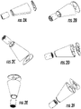
- FIGs. 1 and generally designated at 30 an embodiment of a portable spirometer is shown in FIGs. 1 and generally designated at 30.
- the spirometer 30 is configured to monitor respiration of an individual by measuring the amount of air inhaled and exhaled by an individual for a period of time.
- the spirometer 30 interfaces directly with a computer or a smartphone application using either a physical connection or a wireless connection such that output data may be transmitted.
- the computer or smartphone may include an external display for providing fast and intuitive visualization of the output data without requiring additional manual input on the part of the user.
- such an external display may provide real-time user feedback for ensuring correct usage of the spirometer for the full duration of the test.
- This arrangement simplifies the process of collecting and recording objective data on the condition of the user over time and better enables the user to manage their condition and comply with a treatment plan.
- the spirometer 20 interface with the computer or smartphone application may further comprise a control system which, in turn, may be connected (e.g., wirelessly) to a healthcare provider, caregiver, and the like.
- the spirometer 30 comprises a hollow tubular housing 32 having a proximal end 40 and a distal end 42 and defining a fluid flow pathway and a hollow cylindrical mouthpiece 36 also having a proximal end 35 and a distal end 37.
- the housing 32 has a generally elliptical cross-section and tapers outwardly from the proximal end 40 to the distal end 42. It is understood that the housing 32 may take any shape, although the housing 32 is configured so as to be portable and thus preferably has a size and a shape that makes the spirometer 20 convenient to carry and handle and which may fit into a pocket or a protective pouch. As seen in FIG.
- an outer diameter of a length of the proximal end 40 of the housing 32 is externally threaded 45.
- the proximal end 40 of the housing 32 receives the distal end 37 of the mouthpiece 36 which seats against the shoulder for mounting the mouthpiece 36 to the housing 32.
- the inner diameter of the mouthpiece 36 is the same as the diameter of the fluid flow pathway which is of constant diameter through the length of the housing 32.
- the mouthpiece 36 is configured to fit comfortably within the anatomical parameters of the mouth to ensure easy inhalation and exhalation maneuvers. In this arrangement, the mouthpiece 36 allows the user to inhale or exhale through the fluid flow pathway of the housing 32.
- the mouthpiece 36 can be either reusable or disposable and replaced for each user of the spirometer 30.
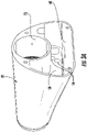
- the fluid flow pathway of the housing 32 accommodates a flow chamber 34 spaced from the proximal end 40 of the housing 32.
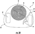
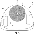
- the flow chamber 34 is a generally cylindrical member and comprises a plurality of cylindrical concentric walls 46, or tubes, defining air flow passages extending in a direction substantially parallel to the longitudinal axis of the housing 32.
- the concentric walls 46 are joined at points along their length by branched flow passages 48 extending perpendicular to the direction of air flow through the tubes.
- the branched flow passages 48 also provide structural support to the tubes relative to one another and to the peripheral wall of the flow chamber 34.
- These structural branched flow passages 48 may be placed at any location throughout the longitudinal axis of the plurality of cylindrical concentric cylinders. In the embodiment shown, the flow passages 48 are placed at two locations midway along the cylinders.
- the number of passages, or annular regions, in the flow chamber 34 may vary.
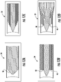
- FIG. 12A an embodiment of the flow chamber 34 is shown having a single air flow passage.
- FIG. 12B is the same embodiment of the flow chamber 34 as shown in FIGs. 5A-5C , wherein the concentric walls 46 define five passages and wherein the proximal ends of the walls 46 align with one another.
- the ends of the concentric walls 46 may be variously aligned.
- the proximal ends of the cylindrical walls 46 may be staggered.
- the passages may have a constant circular cross section. In other embodiments, the cross-sectional shape and area of the passages may vary along their length.
- the walls 46 diverge distally such that cross-sectional area of the passages gradually increase from their proximal end to their distal end.
- the passages similarly gradually decrease in area, or some passages may increase in area and others decrease.
- Alternative embodiments may utilize different variations in the lengths and shapes of the concentric walls 46.
- FIG. 15 Another embodiment of a housing and flow chamber is shown in FIG. 15 and generally designated at 80.
- the flow chamber has a plurality of radial fins 82 circumferentially spaced on the periphery of the flow chamber 34.
- the fins 82 are configured to be received in axial slots 84 defined in the housing 32.
- the fluid flow pathway of the housing 32 defines at least a first fluid inlet opening 50 and a second fluid inlet opening 52 longitudinally spaced from the first fluid inlet opening 50.
- the first fluid inlet opening 50 is positioned between the proximal end 40 of the housing 32 and the proximal end of the flow chamber 34.
- the distance of fluid flow inlet opening 50 is chosen as to maximize the probability of capturing fully developed flow velocity and pressure profiles at that point while minimizing the capture of any turbulence created by the fluid obstructing insert walls 46.
- the first fluid inlet opening 50 extends in a direction perpendicular to the longitudinal axis of the housing 32. Air flow passing from the mouthpiece 36 into the housing 32 passes over the first fluid inlet opening 50.
- the second fluid inlet opening 52 is positioned between the distal end 35 of the flow chamber 34 and the distal end 42 of the housing 32.
- the distance of the second fluid flow inlet opening 52 is chosen as to maximize the probability of capturing fully re-developed flow velocity and pressure profiles at that point, having re-converged after passing through the fluid obstructing insert of the flow chamber 34, while minimizing the capture of any turbulence created by the fluid obstructing insert.
- the second fluid inlet opening 52 extends from the flow chamber 34 in a direction perpendicular to the longitudinal axis of the housing 32. Fluid exiting the passages 46 of the flow chamber 34 passes over the second inlet opening 52.
- the first and second fluid inlet openings 50, 52 will capture complementary but reversed snapshots of the pressure profiles at their respective locations, thereby creating a differential pressure of equal but negative magnitude.
- This embodiment of the spirometer 30 thus can account for bi-directional flow measurement.
- the first fluid inlet opening 50 and the second fluid inlet opening 52 are separately connected via dedicated fluid flow tubes 54 to input measurement points of a differential pressure sensor 38.
- the differential pressure sensor 38 comprises a transducer.
- the differential pressure sensor 38 is disposed in the distal end of the housing 32 opposite the mouthpiece 36.
- the air flow tubes 54 internally connect the points at which the pressure in the cavity is measured to the inputs of the differential pressure transducer 38.
- the separate inputs of the pressure transducer 38 are sealingly connected to the tubes 54 via short connectors 56 to guard against pressure loss due to air escaping.
- the connectors 56 are made of vinyl tubing and in other embodiments may be affixed directly with adhesives.
- the tubes 56 may open through holes in a distal end wall 58 of the housing 32. Thus there is fluid communication between the housing 32 on either side of the flow chamber 34 and the differential pressure sensor 38.
- air pressure may be measured at more than one point around the circumference of the flow chamber in order to average local pressure fluctuations.
- there may be sub-channels connecting the individual sets of measurement points as long as fluid communication between the first and second air flow inlet openings 50, 52 utilize a continuously connected path between the flow chamber 34 and the pressure sensor 38.
- the distal end of the housing 32 is configured to house the electronics necessary for operation of the spirometer 30.
- An electronic circuit associated with the spirometer is on a printed circuit board (PCB) mounted beneath the outlets for the tubes 54.
- PCB printed circuit board
- a PCB 60 is employed that is made according to FR4 170Tg/290Td standards, containing woven fiberglass, flame resistant epoxy resin, ENIG (gold) finish, with copper traces.
- ENIG gold
- the differential pressure sensor 38 is attached to the PCB 60.
- a removable lithium battery fits into a slot 62 in the end wall 58 of the housing 32 and is operatively connected for providing power to the PCB 60.
- the battery may be rechargeable via a USB 64 or other suitable means. It is understood that other power means such as photovoltaic, capacitance, energy harvesting, combinations thereof, and the like may be used instead of or in addition to the battery. However, a battery is preferred for portability of the spirometer 30.
- the components of the spirometer 30 may be produced by a number of methods, including for example, three-dimensional printing or injection molding, preferably from a light-weight plastic material.
- the housing 32 and the mouthpiece 36 of the spirometer 30 in their current embodiments are manufactured using either acrylonitrile butadiene styrene (ABS) or polylactic acid (PLA) plastics, which are then 3D printed into the desired shape.
- Suitable alternative materials include other plastics, preferably biocompatible; glass; metals; or other relatively durable and lightweight material.
- the spirometer 30 is constructed such that it has a clear front end and back end.
- the spirometer 30 is thus configured to produce a substantially laminar flow of air across a wide dynamic range of flow inputs that are normally observed in inhalation and exhalation maneuvers.
- the configuration acts on the fluid flow so that the fluid flow is converted to a more consistent flow profile.
- the location of the flow chamber 34 between the open proximal end 40 of the housing 32 and the flow sensor 38 at the distal end 42 of the housing 22 linearizes air flow across a range of flow rates causing the flow of air generated by a user at the mouthpiece to become a laminar stable air flow in the midsection area, inclusive of the locations of fluid flow inlets 50 and 52.
- the spirometer 30 is capable of producing a consistently accurate response independent from outside factors and inhalation or exhalation patterns.
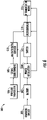
- FIG. 6 is a block schematic diagram of an example of an electronic system 500 in a spirometer for processing the data collected from a flow chamber of the spirometer in accordance with an embodiment of the present invention.
- the electronic system 500 includes a charging circuit 501 for charging a rechargeable battery 502.
- the rechargeable battery is a lithium battery although other type rechargeable batteries, non-rechargeable batteries, or sources of electrical power are also useable.
- the battery 502 is electrically connected to a power regulation circuit 504 that conditions or regulates the electrical power from the battery 502 and supplies the regulated electrical power to a differential pressure transducer 506.
- the differential pressure transducer 506 measures air pressure, which is converted to an air flow rate, from a user in the flow chamber and coverts the air pressure measurements or air flow measurements to corresponding electrical signal that represent data containing the air pressure or flow measurements.
- a signal conditioning circuit 508 receives the electrical signals from the differential pressure transducer 506 and an analog-to-digital converter (ADC) 510 receives the conditioned electrical signals from the signal conditioning circuit 508.
- the ADC 510 samples the electrical signals and generates digital signals representing the air pressure or flow measurement data from measurements in the flow chambers.
- the ADC 510 also received electrical power from the power regulation circuit 504.
- a microcontroller 514 receives the digital air measurement data from the ADC 510.
- the microcontroller 514 controls a switch 512 based on the digital air measurement data from the ADC 510.
- the switch 512 controls operation of the power regulator in supplying electrical power to the differential pressure transducer 506 and the ADC 510.
- the microcontroller 514 is also connected to an RF communications module 516 for wirelessly transmitting the digital air pressure or flow measurement data to a computing device, mobile communications device or other device for further processing the air pressure measurement data, storing and/or displaying the air pressure measurement data. It is contemplated that other device embodiments may perform such calculations onboard the device itself without wireless transmission.
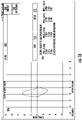
- FIG. 7 is a flow chart of an example of a method 600 for processing the data collected from the flow chamber in accordance with an embodiment of the present invention.
- air pressure or flow measurements are collected from the user as an input to the system.
- the device 602 processes the air pressure or air flow from the user.
- the air pressure or air flow measurements are transduced, conditioned, and sampled.
- the user's air pressure or flow input are transduced, conditioned and sampled by the pressure transducer 506, signal conditioning circuit 508, and sampled by the ADC 510.
- the transduced, conditioned, and sampled signals from block 604 are data encoded and are transmitted by an RF transmitter 608 to a computing device 609 for further processing, storing, and/or displaying the air pressure or flow measurement data.
- Such calculations may include further filtering of the signal for visualization or device utilization, such as Butterworth filtering or Kalman filtering, and mathematical integration of digitized flow rates to calculate lung volumes of the patient at defined intervals.
- the computing device 609 is a mobile computing device, mobile communications device or other device, and it is contemplated that other device embodiments may perform such calculations onboard the device itself without necessarily requiring wireless transmission.
- the encoded data may be transmitted using an RF communications protocol 610, such as Bluetooth protocol or any other wireless communications protocol, inclusive of cellular signals.
- the air pressure or flow measurement data is received by an RF receiver 618 of the computing device 609.
- the received air pressure or flow measurement data is decoded.
- digital signal processing is performed on the decoded data.
- post-processing is performed.
- post-processing includes blocks 622, 624 and 626.
- a recording algorithm receives recording parameter 630.
- the recording parameters 630 may be entered by a user via a user interface (UI) 628.
- the recording parameters 630 include but are not necessarily limited to PEF, FEV1, and total exhaled volume.
- spirometry calculations are performed.
- the results of the spirometry calculations are presented as output graphics and values 632 on a display 633 of the user interface 628.
- guided and incentivized spirometry 634 are also presented on the display 633 of the user interface 628.
- the results of the spirometry calculations are also stored in a data storage device.
- the storage of the data may be on the computing device 609 itself, the device, or on an external server that may be connected wirelessly.
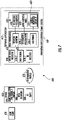
- FIG. 8 is a schematic diagram of an example of the electronic system 700 for processing data collected from a flow chamber of a spirometer in accordance with an embodiment of the present invention.
- the system 700 is used for the system 500 in FIG. 5 .
- the electronic system 700 includes a switching circuit 701 that serves to connect and disconnect electrical power (VCC) from an electrical power source 706 to the remainder of the system 700.
- the switching circuit 701 corresponds to the switch 512 in FIG. 5 .
- the switching circuit 701 may be manually operated via a button (SI) 702, or electronically via a voltage signal from a microcontroller 708 to transistor (T1) 709 of the switching circuit 701.
- a power transistor (Q1) 711 serves to start and stop flow of current from the electrical power source 706.
- a voltage regulator 703 receives electrical power from the switching circuit 701.
- the voltage regulator 703 is connected to bypass capacitors C1 and C2.
- An indicator light (LED2) 707 serves to let the user know whether the device is on or off.
- the output (+3V3) 712 of the voltage regulator 703 powers the microcontroller 708, an RF transceiver 710 and a pressure sensor circuit 704.
- the RF transceiver 710 is a Bluetooth transceiver although any type transceiver is usable.
- the digital pressure sensor circuit 704 includes an internal analog-to-digital (ADC) converter.
- ADC analog-to-digital
- the microcontroller 708 communicates using an I2C protocol.
- Other implementations may include other forms of digital communication (e.g. SPI), or use an analog pressure sensor measured with a discrete analog-to-digital converter.
- the electrical power source 706 includes a rechargeable lithium battery 713 connected to an electrical plug (JP1) 714, and provides electrical power (VCC) to the switch circuit 701.
- the rechargeable lithium battery 713 includes a lithium charging integrated circuit with a charging rate controlled by a resistor (R2) 716.
- a universal serial bus (USB) connector 718 is included to connect the system 700 to an external electrical power source to provide electrical power for charging the lithium battery 713.
- An indicator light (LED1) 720 serves to notify the user about the status of the battery charging.
- the microcontroller circuit 708, which draws electrical power from the voltage regulator 702, receives data from the pressure sensor 704, and transmits the data to the RF transceiver 710.
- the microcontroller 708 also measures the voltage of the battery 713 through a voltage divider formed by resistors R6 and R7, and electrically switches off the electrical power if battery voltage levels are too low in transistor (T1) 709 of the switching circuit 701.
- a crystal 720 connects to the microcontroller 708 and provides a high-precision operating frequency signal.
- the RF transceiver 710 receives measurement data from the microcontroller circuit 708.
- the RF transceiver 710 is connected to decoupling capacitor (C8) 722.
- the RF transceiver 710 transmits the air pressure measurements or air flow measurements to a computing device, such as computing device 609 in FIG. 6 , for further processing, storing and/or presentation to a user as described herein.
- the mouthpiece 36 of the spirometer 30 is inserted into the proximal end 40 of the housing 32.
- a mechanical push-button switch 66 is centrally located on a rear cover 68 adjacent to two LED's 70 that display green or red when illuminated.
- the user first actuates the switch 66 for turning on the spirometer 30.
- the green LED will illuminate when the switch 66 is actuated indicating that the spirometer 30 is powered on. If the green LED is off, the spirometer 30 has run out of battery charge and should be charged via the USB micro connector 64 accessible through the cover plate 68. While the battery is charging, the red LED will turn on to indicate that the battery is being charged.
- the spirometer 30 may be used while the battery is charging.
- the user When the spirometer 30 has been powered on, the user should then select the Bluetooth device on the interface of the mobile application ( FIG. 10 ) corresponding to the device.
- the available Bluetooth device labeled in this example as HC-05, is indicated at 902.
- the user pairs the mobile application with the spirometer by pressing 'Connect' at 900.
- data collected from the device appears in parts 904 and 906. Data may be cleared using part 912, or saved using part 910.
- the user inhales sharply through the mouthpiece 36 at the proximal end 40 of the housing 32 and exhales forcefully.
- the airflow from the user's breath passes through the mouthpiece 36 and into the proximal end 40 of the housing 32.
- the housing 32 functions to funnel air flow into the concentric cylindrical passages of the flow chamber 34 creating a measurable pressure change. Air flow exits the housing through the outlet opening 72.
- the spirometer 30 can be used to measure and provide as output data any of a number of clinical metrics for lung performance parameters, including but not limited to, forced expiratory volume (FEV) at timed intervals such as the FEV1 (one second) test, FEV6 (six second) test, FVC (forced vital capacity), forced expiratory flow (FEF) such as FEF 25-75, and PEF, many of which are displayed at 904.
- FEV forced expiratory volume
- FEF forced expiratory flow
- the rate of flow of the user's breath as a function of the volume exhaled by the user is displayed at 906. This graph is referred to as a flow-volume curve, and is commonly used in clinical practice.
- the user may opt to view a graph of the rate of flow of the user's breath as a function of time by selecting 908.
- the mobile computing device is capable of performing an analysis for each expiration and will display these results on its own screen; however, it is contemplated that other embodiments can perform the same spirometric analyses on
- the spirometer 30 is configured to be coupled to an external display device by a physical connection or a wireless connection.
- the display device may be an external processing unit, such as a smartphone or personal computer, permitting the user to transfer data from the spirometer 30 and display the results on a larger external screen with additional software.
- the term personal computer is meant to include but is not limited to desktop computers, laptop computers, tablets, and the like.
- the spirometer 30 may be coupled to an external display device through one or more coupling devices, such as a USB cable, a serial cable, a headphone cable, a specially configured cord, and combinations therein. Accordingly, embodiments of the spirometer 30 may comprise any of a USB cable, a serial cable, a headphone cable, and combinations thereof.
- the spirometer 30 may also be configured to be coupled to an external display device by a wireless connection.
- the spirometer 30 may be configured to be coupled to an external display device using Bluetooth technology, SMS messages, WIFI technology, GSM technology, infrared transmission, or fiber optics.
- embodiments of the spirometer 30 may comprise a Bluetooth transmitter.
- the display device may be integral with the spirometer 30.
- the spirometer 30 may comprise an LCD display, an LED display, an organic LED display, a raised touch pad, or combinations thereof.
- the mobile phone and the portable computer are connected to the Internet by an Internet gateway device (e.g., a modem).
- the mobile phone and the portable computer may also communicate with the Internet gateway device using WIFI protocols, Bluetooth protocols, and the like.
- the data may be transmitted by the device 30 via a radio link (e.g., the radio link) to the desktop computer, the cellular telephone, the portable computer, and the like.
- the information may be transmitted by the device directly to the Internet gateway device.
- the mobile computing device may contribute related but not necessarily equivalent information to the spirometer 30 and additionally transmit or analyze this information alongside lung function results.
- this information may include geopositional location, local weather forecasts, altitude, temperature, humidity, or any other information that is passively or actively collected by the device or associated devices that may or may not be directly considered as health information.
- such external information may be used collectively with transmitted patient lung function results to train one or more learning algorithms to make a plurality of predictions on how such information may be related to changes in lung function.
- the training, testing, and deployment of such learning algorithms may be done across one or multiple processor units, possibly including the mobile computing device, a remote server, a personal computer, or a combination thereof.
- a personal computer, a connected server, or a smartphone may comprise an application that is used to perform any or all of the following: track or monitor the output data over a period of time or a number of uses, analyze the output data to provide additional lung performance information, display the output data graphically in a variety of formats, interface with other devices for offsite review or interpretation, and combinations thereof.
- all or parts of this physiological information may be shared through a remote server securely in a regulatory compliant manner (e.g. HIPAA in the USA) with health coaches, physicians and other healthcare professionals, family members, electronic medical records, patient registries, clinical trial centers, and/or any other individual, organization, or corporate entity with appropriate permissions.
- a regulatory compliant manner e.g. HIPAA in the USA
- Such information in raw and analyzed form could be used to prevent unnecessary visits to the office of a health care professional or hospital by identifying a negative change in the respiratory function of patients and may further permit remote teleconferencing with at-risk patients.
- the spirometer 30 and associated software may be used to gather lung function data pre- and post-administration of a particular therapy, which may or may not be a small molecule drug, biologic, or the like, to show proper compliance (e.g. 3 times per day) and/or usage (e.g. following a particular protocol to administer the medication).
- a particular therapy which may or may not be a small molecule drug, biologic, or the like
- the act of monitoring of human behavior can change it.
- Providing real-time data to a network may improve compliance.
- Compliance may be directly monitored by the recognition of insufficient usage of a maintenance medication, as revealed by poor improvement in lung function, or may be inferred if spirometry is prescribed alongside a medication and the spirometry tests themselves are found to be missing or incomplete.
- the system in some embodiments can function as a medication reminder for those patients with a consistent dosage treatment plan who miss an application or overuse a medicine.
- the system embodied in the device enables the healthcare provider to better monitor and manage their patients with chronic respiratory disease on a continual basis.
- the system can also function as a means of providing information and education to the patient, sending messages directly to the patient's computing device or a patient support network to educate and generally inform.
- the healthcare provider may access the data to review the airflow measurements to detect potential problems or recommend treatment or changes in treatment.
- the absence of event tracking information might inform a user or caregiver of a missed scheduled medication administration or measurement event, or even a prolonged loss of contact that may indicate a device failure. In some embodiments, this could trigger a message to the appropriate individuals in charge of a patient's care.
- Messages sent to the healthcare system and/or the patient may include SMS cellular telephone messages, recorded voice messages (e.g., including educational information), alerts, alarms, and the like.
- SMS cellular telephone messages e.g., including educational information
- voice messages e.g., including educational information
- alerts, alarms, and the like e.g., a voice message sent to the healthcare system and/or the patient.
- means are provided for assessing changes in the medicine administration and the lung function of a patient and more particularly the onset of a respiratory disease symptoms and concomitant exacerbations. The assessment may be conducted remotely by the healthcare provider or within a healthcare provider's office.
- the healthcare provider may be connected via the Internet and messages to be reviewed by a caregiver may be transmitted and displayed on a secure website.
- the computing device is connected to the Internet via a wired communication link and in another embodiment this link may be wireless.
- the computing device may connect to the web server over the Internet and may display the website using a conventional or specialized web browser application.
- the new spirometer and concomitant software described has many advantages, including in mobile tracking of lung function or the improvement of lung performance. It is contemplated that embodiments of the spirometer may find particular use by non-patients, including but not limited to athletes, runners, bikers, musicians, singers, smokers, ex-smokers, video gamers, children, and the like, to evaluate, track, train, or improve lung function. It is especially contemplated that embodiments of the spirometer are used in connection with an "app" or a computer program to track improvements in lung performance over time.
- the "app" or program may provide user incentives to use the device consistently, inclusive of virtual points that may or may not be redeemable for real life prizes, lottery entries for cash-value rewards, direct or indirect financial compensation, virtual or real (i.e. printable) achievements and certificates, virtual or real (i.e. printable) contracts between the user and themselves or any other real or virtual individual, or any combination thereof.
- the "app" or program could securely and remotely link the user with a health coach, physician, or any other healthcare professional to give personalized verbal encouragement and training incentives via teleconferencing.
- these actions may be mediated directly or indirectly by a virtual avatar that learns the user's behavior and personality via a plurality of learning algorithms and then gives the user personalized feedback or encouragement on their health.
- the "app" or computer program could use animations (e.g. blowing a dandelion using digital exhalation input from the described spirometer), games (e.g. "throwing” darts at a dartboard using digital exhalation input and positional and angular information from the described spirometer), and the like to incentivize use of the spirometer to evaluate, track, train, or improve lung performance.
- the spirometer comprises a key component in an overall comprehensive management platform, which provides the regular use of a lung function test in order to provide objective measures of a user's lung function.
- the device may be used by individuals not afflicted by any particular respiratory disorder for interest in evaluating, tracking, training, or improving lung performance.
- FIGS. 16A and 16B are a flow chart of an example of method 1600 for delivering the contents of a pulmonary rehabilitation program in accordance with an embodiment of the present invention.
- a spirometer is provided for sensing fluid flow from the individual or user breathing through the spirometer.
- the spirometer is similar to any of the embodiments described herein.
- the user breaths into the spirometer by exhaling or inhaling for flowing fluid through the spirometer from the first end to exit the second end.
- flowing fluid is sensed within the spirometer to provide flow data according to the fluid flow.
- lung function is evaluated according to the flow data as described herein.
- the fluid flow measurement data is provided to at least one of a support network computing device and a healthcare provider computing device.
- the support network computing device or the healthcare provider computing device employs any variety or set of learning algorithms to automatically diagnose an individual's respiratory condition based on the flow data or any other user-specific health information in combination with the flow data.
- the lung function results are used to tailor specific, multi-media knowledge modules to the user or individual.
- the multi-media knowledge modules are tailored to a specific disease or set of diseases.
- medication dosing regimens are automatically or manually monitored.
- a virtual avatar may be provided with whom the individual or user interacts.
- secure chat messaging, phone calls, or telehealth conferencing is provided between the individual and any healthcare professional.
- similar patients are identified and grouped into virtual rehabilitation communities or virtual community support groups based on geopositional location, disease severity, track record of using the device, personality preferences, or any combination thereof.
- the virtual community support groups are able to communicate via secure group chat messaging, phone calls, or telehealth conferencing.
- the virtual community support groups also have synchronized behavioral incentives, medication reminders, and task checklists.
- the virtual community support groups are also able to congregationally communicate with a plurality of doctors, nurses, therapists, health coaches, or any combination thereof in real-time via secure group chat messaging, phone calls, or telehealth conferencing.
- a behavioral incentive or disincentive or a set of such behavioral incentives or disincentives, are provided to the individual or user to improve adherence to the rehabilitation program.
- the behavioral incentives or disincentives may include but is not necessarily limited to virtual, real, or transferable (i.e. virtual to real) rewards, achievements, coupons, currencies, cryptocurrencies, non-financial compensation, or any combination thereof at defined or randomized time intervals.
- the behavioral incentives or disincentives are selectively implemented by a plurality of learning algorithms that automatically adapt to the user's behavior or lung function results over time at defined or randomized time intervals.
- the behavioral incentives or disincentives may include animations, games, augmented reality, or any combination thereof whose functions are tied directly or indirectly to lung function readings.
- FIG. 17 is a flow chart of an example of a method 1700 for remotely engaging individuals in clinical trials or research studies in accordance with an embodiment of the present invention.
- block 1702 users who are already using the device or spirometer are notified through the software associated with the device about ongoing clinical trials that they may be eligible for.
- users can digitally sign an informed consent document to share their physiological and demographic information with a clinical trial sponsor, healthcare professional, or any other privileged individual associated with the study.
- a plurality of non-spirometric information is collected and shared by the user alongside his or her personal lung function information.
- the non-spirometric information may be collected by means other than the spirometer.
- a behavioral incentive or disincentive, or a set of such behavioral incentives or disincentives, may be provided to the study subject to improve adherence to study protocol.
- lung function data is automatically sent to a remote, secure server.
- the lung function data is aggregated with other study subject data or with data from other participants in the study and analyzed.
- users are compensated before the study, during the study, after the study, or any combination thereof.
- the users are compensated based on personal or group adherence to a specific clinical trial protocol.
- the study subjects are compensated with virtual, real, or transferable (i.e. virtual to real) rewards, achievements, coupons, currencies, cryptocurrencies, non-financial compensation, or any combination thereof at defined or randomized time intervals.
- each block in the flowchart or block diagrams may represent a module, segment, or portion of instructions, which comprises one or more executable instructions for implementing the specified logical function(s).
- the functions noted in the block may occur out of the order noted in the figures.
- two blocks shown in succession may, in fact, be executed substantially concurrently, or the blocks may sometimes be executed in the reverse order, depending upon the functionality involved.
- a nail and a screw may not be structural equivalents in that a nail employs a cylindrical surface to secure wooden parts together, whereas a screw employs a helical surface, in the environment of fastening wooden parts, a nail and a screw may be equivalent structures.
Landscapes
- Health & Medical Sciences (AREA)
- Life Sciences & Earth Sciences (AREA)
- Engineering & Computer Science (AREA)
- Medical Informatics (AREA)
- Biomedical Technology (AREA)
- Physics & Mathematics (AREA)
- Public Health (AREA)
- General Health & Medical Sciences (AREA)
- Pathology (AREA)
- Veterinary Medicine (AREA)
- Molecular Biology (AREA)
- Surgery (AREA)
- Animal Behavior & Ethology (AREA)
- Biophysics (AREA)
- Heart & Thoracic Surgery (AREA)
- Physiology (AREA)
- Artificial Intelligence (AREA)
- Psychiatry (AREA)
- Computer Networks & Wireless Communication (AREA)
- Computer Vision & Pattern Recognition (AREA)
- Pulmonology (AREA)
- Signal Processing (AREA)
- Fuzzy Systems (AREA)
- Evolutionary Computation (AREA)
- Nursing (AREA)
- Mathematical Physics (AREA)
- Multimedia (AREA)
- Epidemiology (AREA)
- Primary Health Care (AREA)
- Business, Economics & Management (AREA)
- General Business, Economics & Management (AREA)
- Measurement Of The Respiration, Hearing Ability, Form, And Blood Characteristics Of Living Organisms (AREA)
Applications Claiming Priority (7)
| Application Number | Priority Date | Filing Date | Title |
|---|---|---|---|
| US201662383893P | 2016-09-06 | 2016-09-06 | |
| US201762533368P | 2017-07-17 | 2017-07-17 | |
| US201762533361P | 2017-07-17 | 2017-07-17 | |
| US201762534462P | 2017-07-19 | 2017-07-19 | |
| US201762554266P | 2017-09-05 | 2017-09-05 | |
| EP17772155.2A EP3509487B1 (fr) | 2016-09-06 | 2017-09-06 | Spiromètre portable et procédé de surveillance de fonction pulmonaire |
| PCT/US2017/050239 WO2018048875A1 (fr) | 2016-09-06 | 2017-09-06 | Spiromètre portable et procédé de surveillance de fonction pulmonaire |
Related Parent Applications (1)
| Application Number | Title | Priority Date | Filing Date |
|---|---|---|---|
| EP17772155.2A Division EP3509487B1 (fr) | 2016-09-06 | 2017-09-06 | Spiromètre portable et procédé de surveillance de fonction pulmonaire |
Publications (1)
| Publication Number | Publication Date |
|---|---|
| EP4008251A1 true EP4008251A1 (fr) | 2022-06-08 |
Family
ID=59955634
Family Applications (2)
| Application Number | Title | Priority Date | Filing Date |
|---|---|---|---|
| EP21212739.3A Withdrawn EP4008251A1 (fr) | 2016-09-06 | 2017-09-06 | Système numérique de programme de traitement ou de réhabilitation |
| EP17772155.2A Active EP3509487B1 (fr) | 2016-09-06 | 2017-09-06 | Spiromètre portable et procédé de surveillance de fonction pulmonaire |
Family Applications After (1)
| Application Number | Title | Priority Date | Filing Date |
|---|---|---|---|
| EP17772155.2A Active EP3509487B1 (fr) | 2016-09-06 | 2017-09-06 | Spiromètre portable et procédé de surveillance de fonction pulmonaire |
Country Status (5)
| Country | Link |
|---|---|
| US (3) | US10098570B2 (fr) |
| EP (2) | EP4008251A1 (fr) |
| CN (1) | CN109922729A (fr) |
| ES (1) | ES2908130T3 (fr) |
| WO (1) | WO2018048875A1 (fr) |
Families Citing this family (7)
| Publication number | Priority date | Publication date | Assignee | Title |
|---|---|---|---|---|
| CN109922729A (zh) | 2016-09-06 | 2019-06-21 | 维戈尔医疗系统公司 | 便携式肺活量计和用于监测肺功能的方法 |
| CA182299S (en) * | 2018-01-12 | 2020-01-16 | Inofab Saglik Teknolojileri Anonim Sirketi | Pulmonary function testing device |
| GB201809558D0 (en) * | 2018-06-09 | 2018-07-25 | Smiths Medical International Ltd | Spirometer apparatus |
| TR201904781A2 (tr) * | 2019-03-29 | 2020-10-21 | T C Trakya Ueniversitesi | Mi̇kroi̇şlemci̇ kontrollü elektro pnömati̇ksolunum rehabi̇li̇tasyon ci̇hazi |
| EP3741492B1 (fr) * | 2019-05-23 | 2024-04-24 | FRONIUS INTERNATIONAL GmbH | Buse de gaz vecteur |
| CN211183954U (zh) * | 2020-01-17 | 2020-08-04 | 英和采购管理有限公司 | 可拆卸式蓝牙供电装置 |
| DE102020117607A1 (de) | 2020-07-03 | 2022-01-05 | Drägerwerk AG & Co. KGaA | Ermittlungsvorrichtung, Medizingerät, Einstelleinheit, Computerprogrammprodukt, Speichermittel und Verfahren zum Ermitteln einer Kohlenstoffdioxidkonzentration in Messgas |
Citations (10)
| Publication number | Priority date | Publication date | Assignee | Title |
|---|---|---|---|---|
| JPS5751509U (fr) * | 1980-09-09 | 1982-03-25 | ||
| US5722417A (en) * | 1919-06-30 | 1998-03-03 | Garbe; Bernhardt Rudolph | Long function monitoring apparatus flowheads |
| US5750892A (en) * | 1996-09-27 | 1998-05-12 | Teledyne Industries, Inc. | Laminar flow element with inboard sensor taps and coaxial laminar flow guides |
| US6915705B1 (en) * | 2002-04-03 | 2005-07-12 | Ric Investments, Inc. | Flow sensor and flow resistive element |
| US7172557B1 (en) * | 2003-08-29 | 2007-02-06 | Caldyne, Inc. | Spirometer, display and method |
| KR100760065B1 (ko) * | 2006-06-02 | 2007-09-18 | 한국산업기술대학교산학협력단 | 대용량 질량 유량 계측 장치 |
| WO2013088351A1 (fr) * | 2011-12-12 | 2013-06-20 | Koninklijke Philips Electronics N.V. | Capteur d'écoulement à pression différentielle |
| US20150112707A1 (en) * | 2013-10-19 | 2015-04-23 | CoheroHealth, LLC | Interactive respiratory device usage tracking system |
| WO2015066562A2 (fr) * | 2013-10-31 | 2015-05-07 | Knox Medical Diagnostics | Systèmes et méthodes de surveillance de la fonction respiratoire |
| WO2016161036A1 (fr) * | 2015-04-01 | 2016-10-06 | Compliant Games, Inc. | Instrument de thérapie respiratoire offrant des incitations basées sur un jeu, la formation, et collecte de données de télésurveillance |
Family Cites Families (78)
| Publication number | Priority date | Publication date | Assignee | Title |
|---|---|---|---|---|
| US3735752A (en) | 1971-04-07 | 1973-05-29 | J Rodder | Spirometer |
| US4736750A (en) | 1981-04-24 | 1988-04-12 | Valdespino Joseph M | Apparatus for testing pulmonary functions |
| US5137026A (en) * | 1990-01-04 | 1992-08-11 | Glaxo Australia Pty., Ltd. | Personal spirometer |
| CN1027226C (zh) * | 1992-04-18 | 1995-01-04 | 北京航空航天大学 | 一种全过程支持的正负压高频振荡呼吸机的设计方法与仪器 |
| US5360009A (en) * | 1992-08-14 | 1994-11-01 | Qosina Corp. | Spirometer mouthpiece |
| US8092224B2 (en) | 1995-11-22 | 2012-01-10 | James A. Jorasch | Systems and methods for improved health care compliance |
| US5750982A (en) | 1996-04-16 | 1998-05-12 | Eastman Kodak Company | Method of mounting filters on image sensors |
| US5811681A (en) * | 1996-04-29 | 1998-09-22 | Finnigan Corporation | Multimedia feature for diagnostic instrumentation |
| US7636667B2 (en) | 1996-12-23 | 2009-12-22 | Health Hero Networks, Inc. | Network media access control system for encouraging patient compliance with a treatment plan |
| US6203502B1 (en) * | 1997-03-31 | 2001-03-20 | Pryon Corporation | Respiratory function monitor |
| ES2248985T3 (es) * | 1998-03-05 | 2006-03-16 | Zivena, Inc. | Sistema de dosificacion pulmonar. |
| CN2367251Y (zh) | 1998-05-27 | 2000-03-08 | 北京东红技术开发中心 | 数显式电子肺活量计 |
| US6435183B1 (en) * | 1998-09-23 | 2002-08-20 | Brentwood Medical Technology Corp. | Flow sensing device |
| US6699188B2 (en) | 2000-06-22 | 2004-03-02 | Guidance Interactive Technologies | Interactive reward devices and methods |
| CN2436100Y (zh) | 2000-08-14 | 2001-06-27 | 南通衡器厂 | 电子肺活量计 |
| GB2368398A (en) * | 2000-09-27 | 2002-05-01 | Blease Medical Equipment Ltd | Apparatus and method for measuring fluid flow |
| US6585662B1 (en) * | 2001-01-19 | 2003-07-01 | Boston Medical Technologies, Inc. | Pneumotachometer |
| EP1228779A1 (fr) * | 2001-02-01 | 2002-08-07 | Instrumentarium Corporation | Méthode et dispositif pour déterminer un état de flux gazeux zéro dans une conduite bidirectionnelle de gaz |
| US7835925B2 (en) * | 2001-02-20 | 2010-11-16 | The Procter & Gamble Company | System for improving the management of the health of an individual and related methods |
| ES2188405B1 (es) | 2001-10-22 | 2005-02-01 | Servicio De Instrumentacion Hospitalaria, S.L. | Espirometro portatil de pico. |
| CA2386639A1 (fr) | 2002-05-16 | 2003-11-16 | Dynamic Mt Gmbh | Spirometre electronique portatif |
| GB2393356B (en) | 2002-09-18 | 2006-02-01 | E San Ltd | Telemedicine system |
| KR100496195B1 (ko) | 2003-03-14 | 2005-06-17 | 주식회사 헬스피아 | 폐기능 측정 시스템 |
| WO2006102086A1 (fr) | 2005-03-17 | 2006-09-28 | Coifman Robert E | Appareil et procede pour debitmetres de pointe electroniques intelligents |
| DE102005026933B4 (de) | 2005-06-06 | 2010-09-23 | Filt Lungen- Und Thoraxdiagnostik Gmbh | Verfahren und Verwendung einer Vorrichtung zur Durchführung des Verfahrens zur Messung und Analyse von Bestandteilen von exhaliertem Atemgas |
| CA2511070A1 (fr) * | 2005-06-29 | 2006-12-29 | Scireq Scientific Respiratory Equipment Inc. | Cylindre auto-actionne et spirometre a oscillation |
| US7422015B2 (en) * | 2005-11-22 | 2008-09-09 | The General Electric Company | Arrangement and method for detecting spontaneous respiratory effort of a patient |
| US20080177574A1 (en) | 2007-01-22 | 2008-07-24 | Marcos Lara Gonzalez | Systems and Methods To Improve The Efficiencies Of Immunization Registries |
| EP2017586A1 (fr) * | 2007-07-20 | 2009-01-21 | Map-Medizintechnologie GmbH | Moniteur pour appareil de CPAP/ventilateur |
| CN101380233B (zh) * | 2007-09-05 | 2010-12-22 | 深圳迈瑞生物医疗电子股份有限公司 | 基于呼吸力学模块的呼吸功实时监测方法及监测装置 |
| US9005120B2 (en) * | 2008-02-29 | 2015-04-14 | Richard H. Ryan | Vital signs monitoring using personal protective equipment |
| TWM352998U (en) * | 2008-09-18 | 2009-03-21 | Univ Nat Central | Wireless transmission spirometer |
| US20130303930A1 (en) * | 2009-07-22 | 2013-11-14 | John Elefteriades | Game-based incentive spirometer and a method of quantifying and recording performance |
| JP2013501570A (ja) | 2009-08-13 | 2013-01-17 | ラングテク リミテッド | 改良型肺活量計装置及びそれとともに使用するのに有用な方法 |
| US9138167B1 (en) | 2009-09-25 | 2015-09-22 | Krispin Johan Leydon | Means for rendering key respiratory measurements accessible to mobile digital devices |
| US20110125518A1 (en) | 2009-10-02 | 2011-05-26 | Rabin Chandra Kemp Dhoble | Apparatuses, methods and systems for a mobile healthcare manager-based patient comprehension validator |
| WO2011054117A1 (fr) * | 2009-11-09 | 2011-05-12 | Swisstom Ag | Systeme, ensemble capteur et procede de mesure de pression |
| KR101132595B1 (ko) | 2009-12-24 | 2012-04-06 | 주식회사 코스모바이오메디케어 | 휴대형 폐활량계 |
| WO2011140518A1 (fr) | 2010-05-06 | 2011-11-10 | West Wireless Health Institute | Plateforme modulaire polyvalente pour instrumentation médicale mobile |
| US9763626B2 (en) | 2010-09-22 | 2017-09-19 | Breathe.Me Ltd. | Acoustic spirometer system |
| US20130190641A1 (en) | 2010-09-22 | 2013-07-25 | Meytar (Dital) Engineering Limited | Modular acoustic spirometer |
| CN103619390B (zh) * | 2011-05-23 | 2016-01-13 | 佐尔医药公司 | 具有通气质量反馈单元的医疗通气系统 |
| EP2541450A1 (fr) | 2011-07-01 | 2013-01-02 | Stichting Katholieke Universiteit | Système informatique mobile de patient et procédé d'exacerbation de prédiction |
| US20130018240A1 (en) | 2011-07-12 | 2013-01-17 | Mccoy Kim | Body measurement and imaging with a mobile device |
| US9286615B2 (en) | 2011-08-16 | 2016-03-15 | Elwha Llc | Devices and methods for recording information on a subject's body |
| US9443061B2 (en) | 2011-08-16 | 2016-09-13 | Elwha Llc | Devices and methods for recording information on a subject's body |
| US20130053719A1 (en) | 2011-08-22 | 2013-02-28 | William Oren Wekell | Asthma monitoring device |
| US8583459B2 (en) | 2011-12-02 | 2013-11-12 | Trizetto Corporation | System and method for implementing program compliance for health-based rewards |
| CN104010570B (zh) * | 2011-12-27 | 2016-08-24 | 皇家飞利浦有限公司 | 具有集成式过滤器的呼吸测量设备 |
| US20140142456A1 (en) | 2012-04-27 | 2014-05-22 | Control A Plus, LLC | Environmental and patient monitor for providing activity recommendations |
| JP6272308B2 (ja) | 2012-05-10 | 2018-01-31 | ユニバーシティ オブ ワシントン スルー イッツ センター フォー コマーシャリゼーション | 音ベースの肺活量測定のデバイス、システムおよび方法 |
| WO2013177300A1 (fr) | 2012-05-22 | 2013-11-28 | Sparo Labs | Système de spiromètre et méthodes d'analyse de données |
| SE536800C2 (sv) | 2012-06-08 | 2014-08-26 | Pond Innovation & Design Ab | Anordning, förfarande och programvara för att mäta utandningskapacitet |
| WO2013188458A2 (fr) * | 2012-06-13 | 2013-12-19 | The Regents Of The University Of California | Dispositif de surveillance de fonction pulmonaire personnel apte à effectuer une analyse d'air expiré |
| US20140066731A1 (en) | 2012-09-05 | 2014-03-06 | Hcl Technologies Limited | Batteryless Portable Medical Devices |
| US20140073969A1 (en) | 2012-09-12 | 2014-03-13 | Neurosky, Inc. | Mobile cardiac health monitoring |
| US20140081087A1 (en) | 2012-09-14 | 2014-03-20 | Shan-Yi Yu | Mobile device system actively capturing physiological parameters |
| US9086847B2 (en) | 2012-09-25 | 2015-07-21 | Micro Mobio Corporation | Personal cloud case cover with a plurality of modular capabilities |
| US9528865B2 (en) * | 2012-11-02 | 2016-12-27 | Johnson Controls Technology Company | Methods and systems for determining flow direction using a bidirectional pressure sensor |
| EP2948880A1 (fr) | 2013-01-25 | 2015-12-02 | Vanderbilt University | Système intelligent portatif de surveillance de la santé et procédés connexes |
| TWI518629B (zh) | 2013-06-12 | 2016-01-21 | 英特爾股份有限公司 | 用於生理信號之自動化品質評估的方法及設備 |
| WO2014204979A1 (fr) | 2013-06-17 | 2014-12-24 | Monitor My Meds Llc | Adhésion médicamenteuse et accusé de réception |
| GB201310824D0 (en) | 2013-06-18 | 2013-07-31 | Smiths Medical Int Ltd | Respiratory therapy apparatus and methods |
| US20150126889A1 (en) | 2013-11-04 | 2015-05-07 | South Jersey Engineering & Research, LLC | Spirometer comprising piezoelectric sensor |
| US10758132B2 (en) * | 2013-11-27 | 2020-09-01 | Harinath Garudadri | Ambulatory diagnostic device and method thereof |
| TWI530773B (zh) | 2013-12-11 | 2016-04-21 | 宏碁股份有限公司 | 偵測系統、電子裝置以及偵測方法 |
| WO2015117046A1 (fr) | 2014-01-31 | 2015-08-06 | North Carolina State University | Système et procédé de surveillance des paramètres respiratoires |
| WO2015145424A1 (fr) | 2014-03-23 | 2015-10-01 | Doc@Home Ltd | Système de réalisation d'un examen physique à distance |
| US20160015324A1 (en) | 2014-07-17 | 2016-01-21 | Dean Du Bois | System, Method, and Apparatus for Measuring Pulmonary Data |
| US20160015328A1 (en) | 2014-07-18 | 2016-01-21 | Sony Corporation | Physical properties converter |
| CN104188656A (zh) * | 2014-09-01 | 2014-12-10 | 刘敏 | 肺活量测试仪 |
| US20160106342A1 (en) | 2014-10-20 | 2016-04-21 | Mehdi Razavi | Systems and methods for monitoring lung function |
| US20160150995A1 (en) | 2014-11-28 | 2016-06-02 | Breathometer, Inc. | Portable device for personal breath quality and dehydration monitoring |
| EP3050513A1 (fr) | 2015-01-27 | 2016-08-03 | Royal College of Art | Contrôle de débit expiratoire |
| CN204562163U (zh) * | 2015-03-27 | 2015-08-19 | 常州信息职业技术学院 | 一种电子肺活量测量计 |
| US20160363582A1 (en) * | 2015-06-12 | 2016-12-15 | Lunatech, Llc | Breath analyzer |
| US11433211B2 (en) * | 2016-03-17 | 2022-09-06 | Zoll Medical Corporation | Flow sensor for ventilation |
| CN109922729A (zh) | 2016-09-06 | 2019-06-21 | 维戈尔医疗系统公司 | 便携式肺活量计和用于监测肺功能的方法 |
-
2017
- 2017-09-06 CN CN201780068390.8A patent/CN109922729A/zh active Pending
- 2017-09-06 WO PCT/US2017/050239 patent/WO2018048875A1/fr unknown
- 2017-09-06 EP EP21212739.3A patent/EP4008251A1/fr not_active Withdrawn
- 2017-09-06 ES ES17772155T patent/ES2908130T3/es active Active
- 2017-09-06 US US15/696,780 patent/US10098570B2/en active Active
- 2017-09-06 EP EP17772155.2A patent/EP3509487B1/fr active Active
-
2018
- 2018-10-09 US US16/155,193 patent/US11234614B2/en active Active
-
2022
- 2022-01-31 US US17/589,482 patent/US20220218227A1/en active Pending
Patent Citations (10)
| Publication number | Priority date | Publication date | Assignee | Title |
|---|---|---|---|---|
| US5722417A (en) * | 1919-06-30 | 1998-03-03 | Garbe; Bernhardt Rudolph | Long function monitoring apparatus flowheads |
| JPS5751509U (fr) * | 1980-09-09 | 1982-03-25 | ||
| US5750892A (en) * | 1996-09-27 | 1998-05-12 | Teledyne Industries, Inc. | Laminar flow element with inboard sensor taps and coaxial laminar flow guides |
| US6915705B1 (en) * | 2002-04-03 | 2005-07-12 | Ric Investments, Inc. | Flow sensor and flow resistive element |
| US7172557B1 (en) * | 2003-08-29 | 2007-02-06 | Caldyne, Inc. | Spirometer, display and method |
| KR100760065B1 (ko) * | 2006-06-02 | 2007-09-18 | 한국산업기술대학교산학협력단 | 대용량 질량 유량 계측 장치 |
| WO2013088351A1 (fr) * | 2011-12-12 | 2013-06-20 | Koninklijke Philips Electronics N.V. | Capteur d'écoulement à pression différentielle |
| US20150112707A1 (en) * | 2013-10-19 | 2015-04-23 | CoheroHealth, LLC | Interactive respiratory device usage tracking system |
| WO2015066562A2 (fr) * | 2013-10-31 | 2015-05-07 | Knox Medical Diagnostics | Systèmes et méthodes de surveillance de la fonction respiratoire |
| WO2016161036A1 (fr) * | 2015-04-01 | 2016-10-06 | Compliant Games, Inc. | Instrument de thérapie respiratoire offrant des incitations basées sur un jeu, la formation, et collecte de données de télésurveillance |
Also Published As
| Publication number | Publication date |
|---|---|
| US20220218227A1 (en) | 2022-07-14 |
| US11234614B2 (en) | 2022-02-01 |
| US10098570B2 (en) | 2018-10-16 |
| US20180064367A1 (en) | 2018-03-08 |
| ES2908130T3 (es) | 2022-04-27 |
| EP3509487A1 (fr) | 2019-07-17 |
| WO2018048875A1 (fr) | 2018-03-15 |
| US20190069807A1 (en) | 2019-03-07 |
| CN109922729A (zh) | 2019-06-21 |
| EP3509487B1 (fr) | 2021-12-08 |
Similar Documents
| Publication | Publication Date | Title |
|---|---|---|
| US20220218227A1 (en) | Portable spirometer and method for monitoring lung function | |
| US20230213368A1 (en) | Portable spirometer | |
| US10136838B2 (en) | Personal spirometer | |
| US20170273597A1 (en) | Methods and systems for collecting spirometry data | |
| US20090151718A1 (en) | Apparatuses and Methods for Diagnosing and Treating Respiratory Conditions | |
| Kassem et al. | A smart spirometry device for asthma diagnosis | |
| TW200944179A (en) | Measuring system, computer program, set of a measuring device and a computer program and method for operating the measuring system | |
| EP3781028B1 (fr) | Spiromètre électronique portatif | |
| EP3758603A1 (fr) | Dispositif et procédé pour mesurer le débit d'air respiratoire | |
| Kanna et al. | Computational Spirometer Using Arduino Nano Application: Smart Spirometer Module | |
| WO2020058985A1 (fr) | Système de spiromètre portatif | |
| WO2023225407A1 (fr) | Inhalateur intelligent |
Legal Events
| Date | Code | Title | Description |
|---|---|---|---|
| PUAI | Public reference made under article 153(3) epc to a published international application that has entered the european phase |
Free format text: ORIGINAL CODE: 0009012 |
|
| STAA | Information on the status of an ep patent application or granted ep patent |
Free format text: STATUS: THE APPLICATION HAS BEEN PUBLISHED |
|
| AC | Divisional application: reference to earlier application |
Ref document number: 3509487 Country of ref document: EP Kind code of ref document: P |
|
| AK | Designated contracting states |
Kind code of ref document: A1 Designated state(s): AL AT BE BG CH CY CZ DE DK EE ES FI FR GB GR HR HU IE IS IT LI LT LU LV MC MK MT NL NO PL PT RO RS SE SI SK SM TR |
|
| STAA | Information on the status of an ep patent application or granted ep patent |
Free format text: STATUS: THE APPLICATION IS DEEMED TO BE WITHDRAWN |
|
| 18D | Application deemed to be withdrawn |
Effective date: 20221209 |