EP4007423B1 - Methods for latency reduction - Google Patents
Methods for latency reduction Download PDFInfo
- Publication number
- EP4007423B1 EP4007423B1 EP21213978.6A EP21213978A EP4007423B1 EP 4007423 B1 EP4007423 B1 EP 4007423B1 EP 21213978 A EP21213978 A EP 21213978A EP 4007423 B1 EP4007423 B1 EP 4007423B1
- Authority
- EP
- European Patent Office
- Prior art keywords
- data
- modem
- grant
- mts
- wireless
- Prior art date
- Legal status (The legal status is an assumption and is not a legal conclusion. Google has not performed a legal analysis and makes no representation as to the accuracy of the status listed.)
- Active
Links
Images


Classifications
-
- H—ELECTRICITY
- H04—ELECTRIC COMMUNICATION TECHNIQUE
- H04W—WIRELESS COMMUNICATION NETWORKS
- H04W28/00—Network traffic management; Network resource management
- H04W28/16—Central resource management; Negotiation of resources or communication parameters, e.g. negotiating bandwidth or QoS [Quality of Service]
- H04W28/18—Negotiating wireless communication parameters
- H04W28/20—Negotiating bandwidth
-
- H—ELECTRICITY
- H04—ELECTRIC COMMUNICATION TECHNIQUE
- H04W—WIRELESS COMMUNICATION NETWORKS
- H04W28/00—Network traffic management; Network resource management
- H04W28/02—Traffic management, e.g. flow control or congestion control
- H04W28/0278—Traffic management, e.g. flow control or congestion control using buffer status reports
-
- H—ELECTRICITY
- H04—ELECTRIC COMMUNICATION TECHNIQUE
- H04W—WIRELESS COMMUNICATION NETWORKS
- H04W28/00—Network traffic management; Network resource management
- H04W28/02—Traffic management, e.g. flow control or congestion control
- H04W28/0268—Traffic management, e.g. flow control or congestion control using specific QoS parameters for wireless networks, e.g. QoS class identifier [QCI] or guaranteed bit rate [GBR]
-
- H—ELECTRICITY
- H04—ELECTRIC COMMUNICATION TECHNIQUE
- H04W—WIRELESS COMMUNICATION NETWORKS
- H04W28/00—Network traffic management; Network resource management
- H04W28/16—Central resource management; Negotiation of resources or communication parameters, e.g. negotiating bandwidth or QoS [Quality of Service]
- H04W28/24—Negotiating SLA [Service Level Agreement]; Negotiating QoS [Quality of Service]
-
- H—ELECTRICITY
- H04—ELECTRIC COMMUNICATION TECHNIQUE
- H04W—WIRELESS COMMUNICATION NETWORKS
- H04W72/00—Local resource management
- H04W72/12—Wireless traffic scheduling
- H04W72/1263—Mapping of traffic onto schedule, e.g. scheduled allocation or multiplexing of flows
- H04W72/1268—Mapping of traffic onto schedule, e.g. scheduled allocation or multiplexing of flows of uplink data flows
-
- H—ELECTRICITY
- H04—ELECTRIC COMMUNICATION TECHNIQUE
- H04W—WIRELESS COMMUNICATION NETWORKS
- H04W72/00—Local resource management
- H04W72/20—Control channels or signalling for resource management
- H04W72/21—Control channels or signalling for resource management in the uplink direction of a wireless link, i.e. towards the network
-
- H—ELECTRICITY
- H04—ELECTRIC COMMUNICATION TECHNIQUE
- H04W—WIRELESS COMMUNICATION NETWORKS
- H04W72/00—Local resource management
- H04W72/50—Allocation or scheduling criteria for wireless resources
- H04W72/54—Allocation or scheduling criteria for wireless resources based on quality criteria
- H04W72/542—Allocation or scheduling criteria for wireless resources based on quality criteria using measured or perceived quality
-
- H—ELECTRICITY
- H04—ELECTRIC COMMUNICATION TECHNIQUE
- H04W—WIRELESS COMMUNICATION NETWORKS
- H04W72/00—Local resource management
- H04W72/50—Allocation or scheduling criteria for wireless resources
- H04W72/56—Allocation or scheduling criteria for wireless resources based on priority criteria
-
- H—ELECTRICITY
- H04—ELECTRIC COMMUNICATION TECHNIQUE
- H04W—WIRELESS COMMUNICATION NETWORKS
- H04W76/00—Connection management
- H04W76/10—Connection setup
- H04W76/14—Direct-mode setup
-
- H—ELECTRICITY
- H04—ELECTRIC COMMUNICATION TECHNIQUE
- H04W—WIRELESS COMMUNICATION NETWORKS
- H04W84/00—Network topologies
- H04W84/02—Hierarchically pre-organised networks, e.g. paging networks, cellular networks, WLAN [Wireless Local Area Network] or WLL [Wireless Local Loop]
- H04W84/10—Small scale networks; Flat hierarchical networks
- H04W84/12—WLAN [Wireless Local Area Networks]
-
- H—ELECTRICITY
- H04—ELECTRIC COMMUNICATION TECHNIQUE
- H04W—WIRELESS COMMUNICATION NETWORKS
- H04W84/00—Network topologies
- H04W84/02—Hierarchically pre-organised networks, e.g. paging networks, cellular networks, WLAN [Wireless Local Area Network] or WLL [Wireless Local Loop]
- H04W84/04—Large scale networks; Deep hierarchical networks
- H04W84/042—Public Land Mobile systems, e.g. cellular systems
Definitions
- the present invention relates to systems and methods for latency reduction.
- MNOs Mobile Network Operators
- UEs wireless user equipment
- the wireless networks of these MNOs exist in a variety of forms and operate using a variety of modulations, signaling techniques, and protocols, such as those found in Wifi, 3G, 4G, 5G and Long Term Evolution (LTE) networks.
- MSOs Multiple-System Operators
- telcos Telecommunications Companies
- satellite operators including high speed satellite broadband services
- fiber operators and UAV internet providers
- Operators routinely provide internet services to the MNOs for backhaul traffic, while the MNO provides wireless services for the Operator.
- some Operators operate both the wired services and MNO services.
- MSOs are even providing "small cells" such that a UE can communicate through its MNO via an MSO.
- an MSO may deploy an antenna/interface that a UE can communicate with via its respective wireless protocol.
- the MSO packages the communications between the UE and the MNO via the MSO's protocol, for example Data Over Cable Service Interface Specification (DOCSIS).
- DOCSIS Data Over Cable Service Interface Specification
- latency is incurred because of the serial nature of data transfer grants between DOCSIS and the wireless protocol.
- MSOs are even providing "small cells" such that a UE can communicate through its MNO via an MSO.
- an MSO may deploy an antenna/interface that a UE can communicate with via its respective wireless protocol.
- the MSO packages the communications between the UE and the MNO via the MSO's protocol, for example Data Over Cable Service Interface Specification (DOCSIS).
- DOCSIS Data Over Cable Service Interface Specification
- functionality of a small cell may be spread across a communication link via virtualization of the components thereof. But, granting data transfer requests from UEs through the communication link is problematic because latency incurs from the serial nature of data transfer grants between the wireless protocol and that of the communication link.
- an MSO may deploy an antenna/interface that a UE can communicate with via its respective wireless protocol.
- the MSO packages the communications between the UE and the MNO's mobile core via the MSO's protocol, for example Data Over Cable Service Interface Specification (DOCSIS).
- DOCSIS Data Over Cable Service Interface Specification
- QoE Quality of Experience
- MNOs Mobile Network Operators
- UEs user equipment
- the wireless service network can consist of macro and/or small cells.
- MNOs operate with Multi System Operators (MSOs) of the cable industry for backhauling traffic for wireless networks.
- MSOs Multi System Operators
- the MSO packages the communications between the UE and the MNO via the MSOs protocol, for example Data Over Cable Service Interface Specification (DOCSIS).
- DOCSIS Data Over Cable Service Interface Specification
- DOCSIS backhaul networks and wireless radio networks each lack visibility into the other's network operations and data. This causes the scheduling algorithms for the wireless and DOCSIS network to operate separately, which can result in serial operations during the transfer of data from UE to the mobile core.
- the DOCSIS network does not have insights into the amount and the priority of wireless data being backhauled, since this knowledge is only known to the wireless portion of the network.
- WO 2015/129985 A1 describes a method and apparatus for transmitting uplink data having low latency in a wireless communication system.
- a method includes linking a modem to a Modem Termination System (MTS) via the DOCSIS communication link and detecting, at the modem, a message from a wireless service link indicating that a user equipment (UE) has data to transmit to a Mobile Network Operator (MNO).
- MTS Modem Termination System
- MNO Mobile Network Operator
- An optical network may be formed with, for example, an Optical Network Terminal (ONT) or an Optical Line Termination (OLT), and an Optical Network Unit (ONU), and may utilize optical protocols such as EPON, RFOG, or GPON.
- ONT Optical Network Terminal
- OLT Optical Line Termination
- ONU Optical Network Unit
- Embodiments also contemplated exist in other communication systems capable of backhauling traffic, for example, a satellite operator's communication system.
- a termination unit such as a CMTS, an ONT, an OLT, a Network Termination Units, a Satellite Termination Units, and other termination systems are collectively called a "Modem Termination System (MTS)".
- MTS Modem Termination System
- a modem unit such as a satellite modem, a modem, an Optical Network Units (ONU), a DSL unit, etc. collectively called a “modem.”
- a protocol such as DOCSIS, EPON, RFOG, GPON, Satellite Internet Protocol, is called a "protocol.”
- the present system and method handles a data request for transmitting from a modem to a mobile core via the wireless service link.
- the processing of the data request from the modem occurs at least in part at the MTS.
- the system and method are capable of processing a wireless request to result in a wireless grant substantially simultaneous to the backhaul negotiation of the transmission of UE data over the backhaul network.
- the UE is an LTE wireless device in wireless communication with an eNodeB, although it will be understood that the present invention is equally applicable for use with 2G, 3G, 5G, and other wireless protocol systems.
- the communication link comprises a virtualized Modem Termination System (vMTS) and a modem.
- the communication link is coupled with a virtualized wireless link (e.g., configured from a remote small cell and a central small cell).
- vMTS virtualized Modem Termination System
- the communication link is coupled with a virtualized wireless link (e.g., configured from a remote small cell and a central small cell).
- a virtualized wireless link e.g., configured from a remote small cell and a central small cell.
- An optical network may be formed with, for example, an Optical Network Terminal (ONT) or an Optical Line Termination (OLT), and an Optical Network Unit (ONU), and may utilize optical protocols such as EPON, RFOG, or GPON.
- ONT Optical Network Terminal
- ONT Optical Line Termination
- ONU Optical Network Unit
- Embodiments also contemplated exist in other communication systems capable of backhauling traffic, for example, a satellite operator's communication system.
- a termination unit such as a CMTS, an ONT, an OLT, a Network Termination Units, a Satellite Termination Units, and other termination systems are collectively called a "Modem Termination System (MTS)".
- MTS Modem Termination System
- a modem unit such as a satellite modem, a modem, an Optical Network Units (ONU), a DSL unit, etc. collectively called a "modem.”
- a protocol such as DOCSIS, EPON, RFOG, GPON, Satellite Internet Protocol, is called a "protocol.”
- the present system and method handles transferring a bandwidth request message, such as a buffer status report (BSR), from a UE through the communication link to a control portion of the virtualized wireless link, for example residing with the central Small Cell (cSC).
- BSR buffer status report
- the control portion of the virtualized wireless link signals the vMTS to generate a grant, (e.g., a backhaul grant), for the transmission of the UE data on the communication link.
- the control portion of the virtualized wireless link also generates a wireless grant for the UE to transfer the data on the virtualized wireless link.
- control portion of the virtualized wireless link e.g., the central Small Cell (cSC)
- cSC central Small Cell
- the control portion of the virtualized wireless link may be configured in a cloud computing system in communication with the wireless core or may be configured in the wireless core.
- the control portion of the virtualized wireless link may be configured with an MTS or vMTS.
- control portion of the virtualized wireless link signals of a grant for the transmission of the UE data on the communication link.
- the control portion of the virtualized wireless link also generates a wireless grant for the UE to transfer the data on the virtualized wireless link.
- a mediator intercepts or generates a copy of one or both of the BSR sent from the UE to the cSC and the UL grant sent from the cSC to the UE.
- the mediator unpacks or otherwise decodes all or a portion of the BSR and/or the UL grant to provide data to the vMTS for the generation of a MAP or an unsolicited grant for transmission to the modem.
- the mediator may be configured with the vMTS or the cSC, configured between the vMTS and the cSC, or configured between the RPD and the vMTS.
- the functionality detailed above for the mediator is integrated into the vMTS itself, such that the vMTS unpacks or otherwise decodes all or a portion of the BSR and/or the UL grant so the vMTS may generate a MAP or an unsolicited grant for transmission to the modem.
- the modem is prepared for the transmission of UL data as soon as it arrives at the modem thereby significantly reducing latency.
- the RPD is replaced with a Remote Device (RD) configured to implement both the PHY and MAC layers (similar to PHY 127 and MAC 126 of FIG. 12 ) and the mediator is configured between the RD and the vMTS.
- the mediator intercepts or generates a copy of one or both of the BSR sent from the UE to the cSC and the UL grant sent from the cSC to the UE.
- the mediator unpacks or otherwise decodes all or a portion of the BSR and/or the UL grant to provide data to a remote device (RD) for the generation of a MAP or an unsolicited grant for transmission to the modem.
- RD Remote Device
- the functionality for the mediator is integrated into the Remote Device itself, such that the RD unpacks or otherwise decodes all or a portion of the BSR and/or the UL grant so the RD may generate a MAP or an unsolicited grant for transmission to the modem.
- the modem is prepared to transmit UL data as soon as it arrives at the modem, thereby significantly reducing latency.
- the UE implements LTE protocol, although it will be understood that the present invention is equally applicable for use with 2G, 3G, 5G, Wi-Fi and other wireless protocol systems.
- the Modem 102 implements DOCSIS protocol, although it will be understood that the present invention is equally applicable for use with satellite, EPON, GPON, and other wired protocol systems.
- a method comprises intercepting setup information for a wireless session from a mobile core (e.g., operated by an MNO) servicing the UE, initiating a communication session between a Modem Termination System (MTS) and a modem based on the intercepted setup information to support a forthcoming wireless session, and providing the wireless session through the communication session setup.
- a mobile core e.g., operated by an MNO
- MTS Modem Termination System
- An optical network may be formed with, for example, an Optical Network Terminal (ONT) or an Optical Line Termination (OLT), and an Optical Network Unit (ONU), and may utilize optical protocols such as EPON, RFOG, or GPON.
- ONT Optical Network Terminal
- OLT Optical Line Termination
- ONU Optical Network Unit
- Embodiments also contemplated exist in other communication systems capable of backhauling traffic, for example, a satellite operator's communication system.
- a termination unit such as a CMTS, an ONT, an OLT, a Network Termination Units, a Satellite Termination Units, and other termination systems are collectively called a "Modem Termination System (MTS)".
- MTS Modem Termination System
- a modem unit such as a satellite modem, a modem, an Optical Network Units (ONU), a DSL unit, etc. collectively called a “modem.”
- a protocol such as DOCSIS, EPON, RFOG, GPON, Satellite Internet Protocol, is called a "protocol.”
- the UE is an LTE wireless device, although it will be understood that the present invention is equally applicable for use with 2G, 3G, 5G, Wi-Fi and other wireless protocol systems.
- An optical network may be formed with, for example, an Optical Network Terminal (ONT) or an Optical Line Termination (OLT), and an Optical Network Unit (ONU), and may utilize optical protocols such as EPON, RFOG, or GPON.
- ONT Optical Network Terminal
- OLT Optical Line Termination
- ONU Optical Network Unit
- Embodiments also contemplated exist in other communication systems capable of x-hauling traffic examples include without limitation satellite operator's communication systems, Wi-Fi networks, optical networks, DOCSIS networks, MIMO communication systems, microwave communication systems, short and long haul coherent optic systems, etc.
- X-hauling is defined here as any one of or a combination of front-hauling, backhauling, and mid-hauling.
- a termination unit such as a CMTS, an ONT, an OLT, a Network Termination Units, a Satellite Termination Units, and other termination systems are collectively called a "Modem Termination System (MTS)".
- MTS Modem Termination System
- a modem unit such as a satellite modem, a modem, an Optical Network Units (ONU), a DSL unit, etc. collectively called a “modem.”
- a protocol such as DOCSIS, EPON, RFOG, GPON, Satellite Internet Protocol, is called a "protocol.”
- the present latency reduction in wireless service system and method may equally be applied in systems utilizing macrocells, WiFi, satellite communication systems, optical backhaul systems (EPON, GPON, RFOG), MU-MIMO, laser communication, and even aerial vehicles such as unmanned aerial vehicles (UAV) and balloons that provide wireless and/or laser communication. That is, the present invention may be used in many wireless-to-backhaul systems where at least one of the wireless system or backhaul system utilizes a request-grant protocol for data transmission.
- a LTE-DOCSIS cooperative network for expediting a grant assignment for a wireless service through a request-grant based communication link between a user device (e.g., a UE) and a wireless core (also called herein a "first network core", e.g., a mobile core or Wi-Fi core).
- a LTE-DOCSIS cooperative network may be any first network-second network cooperative communication system and is not limited to either LTE or DOCSIS networks.
- the present system and method may be used in a polling service based system, such as Real-Time Publish-Subscribe (RTPS). Polling is similar enough to a request-grant system that it may take advantage of the present invention.
- RTPS Real-Time Publish-Subscribe
- the present system and method for prioritized grant assignment in wireless services may equally be applied in systems utilizing microcells, picocells, macrocells, Wi-Fi, satellite communication systems, optical backhaul systems (EPON, GPON, RFOG), MU-MIMO, laser communication, and even aerial vehicles such as unmanned aerial vehicles (UAV) and balloons that provide wireless and/or laser communication. That is, the present invention may be used in many wireless-to-backhaul systems where at least one of the wireless system or backhaul system utilizes a request-grant protocol for data transmission.
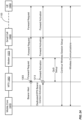
- FIG. 1 is a block diagram of an exemplary wireless service link 100 including a mediator 109 configured with an MTS 106.
- mediator 109 may be integrated with or communicatively coupled with MTS 106.
- the MTS 106 may be, for example, a CMTS, a Fiber Node, a Fiber Hub, an optical network unit (ONU), or other termination device.
- Mediator 109 may be implemented, for example, as a software agent in any of such devices. If mediator 109 is integrated with an MTS, integration may be via software or hardware.
- a UE 105 may wirelessly communicate with other UEs (not shown) in a wireless service network for the purpose of transmitting and/or receiving data.
- a mobile core 107 i.e., operated by an MNO
- Mediator 109 cooperates with the MTS to provide a communication link between the UE 105 and the mobile core 107 such that the mobile core 107 can control the operations of the UE 105, for example, when the UE 105 is within range of a "small cell" 103.
- MNOs In the past, MNOs often maintained, operated, and controlled wireless base stations themselves for the purposes of providing communications with UEs.
- an MNO employing LTE communications may operate a plurality of eNodeBs in an area to provide wireless services to subscribing UEs in that area.
- MSOs are seeking to increase their value to the MNOs by providing alternative backhaul paths for communication between UEs, such as UE 105, and the mobile core, such as mobile core 107.
- MSOs and small/independent wireless operators currently employ wireless devices, such as the small cell 103, for capturing a wireless data transmission and passing it through a backhaul system, as shown in FIG. 1 .
- the backhaul system includes modem 102, MTS 106, and meditator 109 and may additionally include an optional agent 104, which is discussed further below.
- the small cell 103 comprises many of the features of a larger base station such as the air-to-air interface and protocol handling.
- the small cell 103 may be a multi-radio hotspot providing for WiFi, as well as LTE Licensed Assisted Access (LTE-LAA) or LTE Unlicensed (LTE-U).
- LTE-LAA LTE Licensed Assisted Access
- LTE-U LTE Unlicensed
- communication is only WiFi communication and is between a STA (not shown) a WiFi core (not shown).
- STA WiFi station
- WiFi core not shown
- Small cells and similar wireless technologies represent new opportunities for MNOs. These new small cells allow operators to access additional spectrum, use existing spectrum more efficiently, and promote greater deployment flexibility, all at a lower cost. Small cells also reduce radio access network build-out and backhaul investment, while improving the end user experience by providing increased access to mobile networks. Additionally, because small cells are much smaller, they can reduce a base station's footprint and have less environmental impact (e.g., in terms of power consumption).
- the MSOs and MNOs generally employ different communication protocols and offer little insight to each other.
- the MSOs may employ the DOCSIS protocol to transport data to and from a modem 102.
- the MNOs may employ a variety of wireless protocols including EDGE (Enhanced Data rates for GSM Evolution), 2G, 3G, 4G, 5G, LTE, or the like.
- EDGE Enhanced Data rates for GSM Evolution
- 2G, 3G, 4G, 5G, LTE Long Term Evolution
- the MTS and the modem need not process the data transmitted. Rather, the MTS and the modem simply route the traffic between the appropriate parties. In the example of FIG. 1 , traffic is routed between UE 105 and mobile core 107 via small cell 103, modem 102, and MTS 106.
- This lack of insight by the backhaul system into the wireless system's data, and vice versa causes the grant of a request to transmit data across the wireless service link 100 to occur in a serial manner.
- the small cell 103 provides a grant to the UE 105 to transfer data to the small cell 103
- the modem 102 and the MTS 106 are unaware that the small cell 103 has provided a grant for a data transfer from the UE 105.
- the data arrives at the small cell 103 it is then forwarded to the modem 102. Only when the data arrives at the modem 102 from the small cell 103 does the modem transmit a request to the MTS 106.
- the modem-to-MTS grant alerts the MTS 106 that the modem 102 has data to transmit and requires resources to do so.
- the MTS 106 can then schedule resources for the modem 106 and transmits that as a "grant" back to the modem 102.
- the data is then transferred from the modem 102 to the MTS 106 and then forwarded on to the mobile core 107. This serial granting of data transfers results in unnecessary latency to the overall data transfer from UE 105 to mobile core 107.
- the unnecessary latency may result in the data being irrelevant by the time it reaches the intended recipient.
- the UE 105 transfers blocks of data representing relatively small portions of a conversation. When some of the blocks of data are delayed, they may no longer be relevant to the conversation and are as such dropped. When this occurs regularly, the quality of the conversation and the user's quality of experience (QoS) are degraded significantly. Similar issues exist when non-voice data is transmitted across the network, such as video data (live or stored), security data, access and control over remotely located resources, machine-to-machine applications, etc.
- the modem 102 learns from the small cell 103 that the UE 105 has issued a scheduling request to transfer data to the small cell 103.
- the small cell 103 may be an eNodeB operable to communicate in an LTE network, or a WiFi Access Point (STA) operable to communicate in a WiFi network.
- the UE 105 when it needs to transfer data across the wireless service link 100, issues a scheduling request (SR) to the eNodeB.
- SR scheduling request
- the eNodeB determines when the UE 105 can transfer data to the eNodeB and issues an uplink (UL) grant to the UE 105.
- the UE 105 then transfers its data to the eNodeB such that the eNodeB can propagate it through the wireless service link 100 to the mobile core 107 operated by an MNO for subsequent processing, routing, and the like.
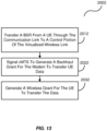
- the UE 105 When the UE 105 has data to transmit the preparation for the transmission process can be a multistep process by itself. For example, if the UE 105 does not have a valid grant, the UE 105 issues an SR then, after receiving the grant, transfers a buffer status report (BSR) to the eNodeB indicating how much data it is requesting to be transferred. The eNodeB then issues the subsequent grant indicating the actual amount of data that can be transmitted. Upon receiving the grant, the UE 105 transfers its data to the eNodeB.
- BSR buffer status report
- the small cell 103 informs the modem 102 of the SR just after the small cell 103 receives it. In an embodiment, this is accomplished by the small cell 103 transmitting an out of band message to the modem 102 to indicate that the small cell 103 has received the SR.
- a modem 102 that is configured with functionality to read the SR may do so.
- the modem 102 may read the SR to learn, for example, that the UE 105 is requesting to transfer data to the small cell 103.
- the modem 102 may be configured with and/or include a portion of an eNodeB such that it can detect and read the LTE protocol, and therefore the SR, from the UE 105.
- the agent 104 may exist between the small cell 103 and the modem 102 (or as a part of the small cell 103 and/or the modem 102). Agent 104 is configured to intercept the SR or generate a copy of the SR during its transit from the small cell 103 to the modem 102, unpacks the SR (or the copy), and transmits an out of band message to the modem 102 pertaining to the data containing within the SR.
- the modem 102 can alert the MTS 106 that it will need to transfer data when the modem 102 receives it from the UE 105 (e.g., through the small cell 103). Alternatively, the modem 102 simply forwards the SR in a manner similar to that of any other received data. It is then up to the MTS 106 or Mediator 109 to process the SR.
- the modem 102 and/or the MTS 106 may be configured to wait until the message is received from the small cell 103 pertaining to the amount of data to be transferred from the UE 105. For example, when the small cell 103 receives an initial SR, the small cell 103 understands that another detailed request will follow with a BSR requesting a data transfer of a particular size. The small cell 103 will then know when that data transfer will occur and how much data will be sent. Accordingly, this information is then conveyed to the modem 102 and/or the MTS 106 to initiate the granting through the backhaul's protocol based on when the actual data transfer will occur and the data size.
- the UE 105 is any device, system, software, or combination thereof operable to communicate wirelessly with a wireless network using any one or more wireless protocols including, 2G, 3G, 4G, 5G, LTE, LTE-U, LTE-LAA, or the like, as well as with a WiFi network using any one or more wireless service protocols including 802.11ax.
- Examples of the UE 105 include, but are not limited to, laptop computers, tablet computers, and wireless telephones such as smart phones.
- the small cell 103 is any device, system, software, or combination thereof operable to provide an air-to-air interface for the mobile core 107, one example of which is a WiFi core.
- Examples of the small cell 103 include WiFi access points and base stations operating as eNodeBs in a wireless network.
- the modem 102 is any device, system, software, or combination thereof operable to provide data transfers with an MTS. Examples of the modem 102 include DOCSIS enabled set-top boxes.
- the MTS 106 is any device, system, software, or combination thereof operable to communicate with the modem 102 as well as provide a wireless service session through the communication link provided by the modem 102 and the MTS 106. Other exemplary embodiments are shown and described below.
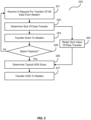
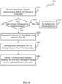
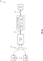
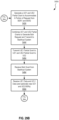
- FIG. 2 is a flowchart illustrating an exemplary process 200 operable with the modem 102 of the wireless service link 100 of FIG. 1 .
- the modem 102 detects a message from a wireless service link 100 indicating that the UE 105 has data to transmit to the mobile core 107, in the process element 201.
- the modem 102 may receive an out of band signaling message from the small cell 103 and/or unpack an SR received by the small cell 103 indicating that the UE 105 requests a data transmission.
- the agent 104 may receive, intercept or generate a copy of an SR sent from the small cell 103 to the modem 102, unpack the SR, and send an out of band signaling message to the modem 102 to alert the modem 102 of the scheduling request by the UE 105.
- the MTS 106 may further anticipate that the modem 102 will send additional signaling messages, such as the BSR message or the grant for the wireless service link 100 issued by the small cell 103, by issuing a grant for the modem 102 over the communication link established between the modem 102 and the MTS 106.
- the BSR message indicates the amount and the quality of service (QoS) requirement of data the UE 105 wishes to transfer to the small cell 103.
- the grant is generated by the small cell 103 for the UE 105 that indicates the amount of data the UE 105 is to transmit and the time of transmission.
- UEs 105(1)-(4) request data transfers to the small cell 103 at or about the same time.
- UE 105(1) needs to transmit two bytes of data
- UEs 105(2) and UEs 105(3) need to transmit four bytes of data each
- UE 105(4) needs to transmit six bytes of data, thus totaling 16 bytes of data.
- the small cell 103 may combine the data transfer information into a BSR for transmission to the MTS 106.
- the MTS 106 may use this information to generate subsequent unsolicited grant of 16 bytes of data such that all of the data from UEs 105(1)-(4) may be transferred at or about the same time.
- the MTS 106 may determine any type of typical unsolicited grant sizes for the modem 102, as shown in process element 226. For example, the MTS 106 may average the data sizes of BSRs from the small cell 103 over time, may use data sizes of one or multiple UEs 105, may base the data sizes of the unsolicited grants on a time of day, or the like. In any case, when the MTS 106 has spare capacity and determines a size of the unsolicited grant, the MTS 106 may transfer the unsolicited to the modem 102, as in process element 227, such that the modem 102 can transfer data of the UE 105 that it receives from the small cell 103.
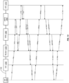
- FIG. 4 is an exemplary communication diagram of the wireless service link 100 of FIG. 1 .
- the small cell 103 is an eNodeB operable within an LTE network and employing LTE communication protocols.
- To the left of the UE 105 are timing diagrams exemplary of the LTE communication protocol. Timing as shown and discussed is not meant to be limiting in anyway, but merely for illustrative purposes and to convey understanding. For example, after a data arrives at the UE, the UE 105 processes the data to determine an SR is needed. The UE 105 waits for 5 ms for an SR opportunity then the UE 105 transfers the SR to the eNodeB 103, which typically takes 1ms.
- the eNodeB 103 process the BSR and generates a second UL grant for the UE 105 in 2 to 4 ms.
- the UE 105 processes the received second grant and prepares the data for transmission, which can take between 2 and 4 ms, then sends the data to the eNodeB 103.
- the eNodeB 103 may, for example, communicate information about the SR to the modem 102 through out of band signaling or transfer the SR to modem 102. If the SR is sent to the modem 102 the SR can be unpacked and modem 102 can determine that the UE 105 has data to be transmitted across the wireless service link 100 and optionally the type of data. In this regard, the modem 102 may request a data transfer from the MTS 106 such that the MTS 106 can begin scheduling for the data of the UE 105. The MTS 106 issues a MAP grant (or some other type of grant) to facilitate the further transfer of BSR and/or LTE grant from the modem 102.
- a MAP grant or some other type of grant
- the eNodeB 103 When the eNodeB 103 receives the BSR, it may transfer the BSR in whole, information about the BSR, the actual LTE grant of the UE 105, or some combination thereof, to the modem 102.
- the LTE grant issued by the eNodeB103 provided information regarding the size and the precise timing at which the UE 105 is scheduled to transmit its data. This, along with BSR, indicates to the modem 102 how much data, at what QoS is to be expected by the UE 105, and the precise time.
- the modem 102 then transfers this information (e.g., the BSR, the LTE grant, or similar as discussed above) to the MTS 106.
- the MTS 106 can transfer a data transfer grant (e.g., a DOCSIS MAP in a cable network embodiment) to the modem 102.
- a data transfer grant e.g., a DOCSIS MAP in a cable network embodiment
- the modem 102 can simply wait for the UL data from the UE 105 and the eNodeB 103 such that it may be immediately forwarded to the MTS 106 through the communication link.
- the MTS 106 Upon receipt of the data the MTS 106 then forwards it to the mobile core 107.
- the MTS may have a gateway configured therewith that is operable to interpret LTE traffic.
- the modem 102 may simply wait until it receives a BSR and transfer it as part of the request for data transmission.
- the MTS 106 may then issue the data transfer grant based on the BSR or the LTE grant info, and the information contained therein.
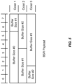
- FIG. 5 is a block diagram of an exemplary buffer status report (BSR) operable with the wireless service link of FIG. 1 .
- the SR is typically a 1-bit indicator sent by UE 105 to request UL bandwidth.
- the SR alone is not sufficient for the eNodeB 103, that is, the eNodeB 103 needs more information about a size of the data to be transmitted from UE 105 before it can provide a data grant to the UE 105. So, the eNodeB 103 simply sends a grant of sufficient size for the transmission of the BSR from the UE 105 to the eNodeB 103.
- the BSR is this configured as a 3-byte MAC control element that reports outstanding data for each of UE 105's four logical channel groups.
- the mapping of a radio bearer (i.e., a logical channel) to a logical channel group (LCG) is done at the session setup time by the eNodeB 103 based on the corresponding QoS attributes of the radio bearers (e.g., QoS Class Identifier (OCI), an Allocation and Retention Priority (ARP), a Guaranteed Bit Rate (GBR), a Maximum Bit Rate (MBR), an Access Point Name-Aggregate Maximum Bit Rate (APN-AMBR), a UE-AMBR, etc.).
- radio resource control (RRC) messages map to LCG0.
- the embodiments herein allow the LCG to be directly mapped to the upstream service flow.
- FIG. 6 is another exemplary communication diagram of the wireless service link 100 of FIG. 1 .
- data transfer grants by the MTS 106 are based upon the BSRs from the UE 105. That is, the UE 105 already has a valid LTE grant, without having to first send the SR. This allows the data requesting/granting to be further compacted and thus further reduces latency within the wireless service link 100.
- the UE 105 issues a BSR to the eNodeB 103. In doing so, the eNodeB 103 transfers the BSR to the modem 102 along with the LTE grant such that the modem 102 knows that the eNodeB 103 will be granting the data transfer to the UE 105.
- the eNodeB 103 then, or at substantially the same time as the BSR/LTE Grant is sent to the modem 102, transfers the UL grant to the UE 105, such that it can transfer its UL data and optionally another BSR (see below) to the eNodeB 103.
- the modem 102 can request a data transfer of the MTS 106 and indicate within that request how much data will be transferred by the UE 105.
- the MTS 106 issues a grant to the modem 102 based on the amount of data, QoS requirement and precise timing of the expected data transfer.
- the UL data is received by the eNodeB 103, it may be transferred by the modem 102 to the MTS 106.
- the UE 105 may also include a BSR for its next transfer of data, as referenced above.
- the eNodeB in transferring the UL data, also transfers the subsequent BSR and/or its LTE grant info for the subsequent data transfer from the UE 105 to the modem 102.
- the modem 102 is able to request a subsequent data transfer of the MTS 106 using the subsequent BSR and/or LTE grant info.
- the MTS 106 transfers the first UL data to the mobile core 107. Then, the MTS 106 issues a second grant to the modem 102 which then waits for the second UL data from the UE 105.
- the UE 105 When the eNodeB 103 issues the second UL grant to the UE 105, the UE 105 responds in turn with the second UL data to the eNodeB 103. The eNodeB 103 forwards this second UL data to the modem 102. As the modem 102 already has its second grant for the second UL data, it immediately transfers the next UL data to the MTS 106, which in turn forwards the next UL data to the mobile core 107.
- the invention can take the form of an entirely hardware embodiment, an entirely software embodiment or an embodiment containing both hardware and software elements.
- Embodiments utilizing network functions virtualization (NFV) and virtualized hardware, such as a virtualized MTS, modem, etc., are also contemplated.
- the invention is implemented in whole or in part in software, which includes but is not limited to firmware, resident software, microcode, etc.
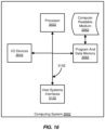
- FIG. 7 illustrates a computing system 300 in which a computer readable medium 306 may provide instructions for performing any of the methods disclosed herein.
- the invention can take the form of a computer program product accessible from the computer readable medium 306 providing program code for use by or in connection with a computer or any instruction execution system.
- the computer readable medium 306 can be any apparatus that can tangibly store the program for use by or in connection with the instruction execution system, apparatus, or device, including the computer system 300.
- the medium 306 can be any tangible electronic, magnetic, optical, electromagnetic, infrared, or semiconductor system (or apparatus or device).
- Examples of a computer readable medium 306 include a semiconductor or solid state memory, magnetic tape, a removable computer diskette, a random access memory (RAM), a read-only memory (ROM), a rigid magnetic disk and an optical disk.
- Some examples of optical disks include compact disk - read only memory (CD-ROM), compact disk - read/write (CD-R/W) and DVD.
- the computing system 300 suitable for storing and/or executing program code, can include one or more processors 302 coupled directly or indirectly to memory 308 through a system bus 310.
- the memory 308 can include local memory employed during actual execution of the program code, bulk storage, and cache memories which provide temporary storage of at least some program code in order to reduce the number of times code is retrieved from bulk storage during execution.
- I/O devices 304 can be coupled to the system either directly or through intervening I/O controllers.
- Network adapters may also be coupled to the system to enable the computing system 300 to become coupled to other data processing systems, such as through host systems interfaces 312, or remote printers or storage devices through intervening private or public networks. Modems and Ethernet cards are just a few of the currently available types of network adapters.
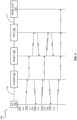
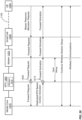
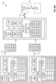
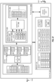
- FIG. 8 is a block diagram of an exemplary system operable to provide wireless service for a plurality of UEs 105-1 - 105-N (where "N” is simply intended to represent an integer greater than “1” and not necessarily equal to any other "N” reference designated herein).
- upstream and downstream links of an exemplary communication system offers high speed data services over connected devices, such as the modem 102.
- the modem 102 may be configured with or receive communications from the small cell 103 so as to allow the UEs 105 to communicate through the communication system in a manner that is transparent to the user.
- the communication system includes a communication component 401 configured with an upstream hub 420.
- the hub 420 is coupled to a fiber node 421 via optical communication links 405 and 406.
- the hub 420 includes a Modem Termination System (MTS) 106 an electrical to optical converter 403, and an optical to electrical converter 404.
- the node 421 is similarly configured with an optical to electrical converter 408 and an electrical to optical converter 407.
- MTS Modem Termination System
- the communication component 401 is the source for various communication signals. Antennas may receive communication signals that are converted as necessary and transmitted over fiber optic cables 405 to the hub 420. Several hubs may be connected to a single communication component 401 and the hub 420 may each be connected to several nodes 421 by fiber optic cable links 405 and 406.
- the MTS 106 may be configured in the communication component 401 or in the hub 420.
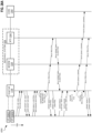
- Downstream such as in homes/businesses, are devices that operate as data terminals. These data terminals are modems.
- a modem can acts as a host for an Internet Protocol (IP) device such as personal computer.
- IP Internet Protocol
- the modem can be configured with a small cell so as to provide wireless services through the system for the UEs 105-1 - 105-N.
- Transmissions from the MTS 106 to the modem are carried over the downstream portion of the communication system generally in the band between 54 MHz and 3 GHz, for example.
- Downstream digital transmissions are continuous and are typically monitored by many modems.
- Upstream transmissions from the modems to the MTS 106 are, for example, typically carried in the 5-600 MHz frequency band, the upstream bandwidth being shared by the Modems that are on-line. However, with greater demands for data, additional frequency bands and bandwidths are continuously being deployed in the downstream and upstream paths. It is also possible that Modems and the MTS engage in full duplex transmission modes, whereby concurrent transmissions on the upstream and the downstream over the same frequency is supported.
- Equivalent communications and protocols for fiber optic transmissions are also contemplated. For example using an optical network terminal (ONT) or optical line termination (OLT), and an optical network unit (ONU), and equivalent protocols such as EPON, RFOG, or GPON.
- ONT optical network terminal
- ONT optical line termination
- ONU optical network
- the MTS 106 connects the system to the Internet backbone.
- the MTS 106 connects to the downstream path through an electrical to optical converter 404 that is connected to the fiber optic cable 406, which in turn, is connected to an optical to electrical converter 408 at the node 421.
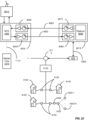
- the signal is transmitted to a diplexer 409 that combines the upstream and downstream signals onto a single cable.
- the diplexer 409 allows the different frequency bands to be combined onto the same cable.
- the downstream channel width in the United States is generally 6 megahertz to 192 MHz with the downstream signals being transmitted in the 54 MHz to 3 GHz band. Upstream signals are presently transmitted between 5 and 600 MHz, but again other bands are being considered to provide increased capacity.
- the signal is typically carried by a coaxial cable 430.
- a power inserter 410 may be used to power the coaxial line equipment, such as amplifiers or other equipment.
- the signal may be split with a splitter 411 to branch the signal.
- bi-directional amplifiers 412 may boost and even split the signal.
- Taps 413 along branches provide connections to subscriber's homes 414 and businesses.
- Upstream transmissions from subscribers to the hub 420/headend 401 occur by passing through the same coaxial cable 430 as the downstream signals, in the opposite direction on a different frequency band.
- the upstream signals are sent typically utilizing Quadrature Amplitude Modulation (QAM) with forward error correction.
- QAM Quadrature Amplitude Modulation
- the upstream signals can employ QPSK or any level of QAM, including 8 QAM, 32 QAM, 64 QAM, 128 OAM, 256 QAM, 512 QAM, 1024 QAM, and 4096 QAM.
- Modulation techniques such as Synchronous Code Division Multiple Access (S-CDMA) and Orthogonal Frequency Division Multiple Access (OFDMA) can also be used. Of course, any type of modulation technique can be used, as desired.
- Upstream transmissions in this embodiment, can be sent in a frequency/time division multiplexing access (FDMA/TDMA) scheme.
- the diplexer 409 splits the lower frequency signals from the higher frequency signals so that the lower frequency, upstream signals can be applied to the electrical to optical converter 407 in the upstream path.
- the electrical to optical converter 407 converts the upstream electrical signals to light waves which are sent through fiber optic cable 405 and received by optical to electrical converter 403 in the node 420.
- the fiber optic links 405 and 406 are typically driven by laser diodes, such as Fabry Perot and distributed feedback laser diodes. Laser diodes begin to "lase" at a certain diode threshold current.
- FIG. 9 is an exemplary communication diagram of the wireless service link employing WiFi.
- the communication diagram is illustrated as part of a WiFi system that provides latency reduction in wireless service.
- the communication link established between the modem 102 and the MTS 106 interfaces with a WiFi core 501 as well as an access point (AP) 502 (e.g., wireless access point or "WAP").
- the AP 502 communicates with a WiFi station (STA) 503 such that the STA 503 can transmit data to the WiFi core 501.
- STA WiFi station
- the STA 503 issues a "request to send" to the AP 502 when the STA 503 needs to transmit data to the WiFi core 501.
- the AP 502 transfers a request to the modem 102 asking the modem 102 if the AP 502 can transfer the data of the STA 503.
- the AP 502 determines that the STA 503 can transfer its data
- the AP 502 transfers a "clear to send" to the STA 503.
- the modem 102 issues a request to transfer data to the MTS 106.
- the MTS 106 issues a MAP (or some other granting mechanism) to the modem 102 allowing the modem 102 to transfer the data of the STA 503.
- the modem 102 waits for the data from the AP 502.
- the AP 502 transfers it directly to the modem 102 such that the modem 102 can transfer the data of the STA 503 through the communication link established between the modem 102 and the MTS 106.
- the MTS 106 receives the data of the STA 503, the MTS 106 transfers a data of the STA 503 to the WiFi core 501.
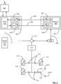
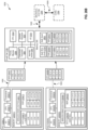
- FIG. 10 is a block diagram of an exemplary communication link comprising a virtualized Modem Termination System (vMTS) 1062, a remote PHY device (RPD) 1082, and a modem 1022.
- the communication link is coupled with a virtualized wireless link (e.g., configured from a remote small cell (rSC) 1032 and a central small cell (cSC) 1072 described in greater detail below).
- a mediator 1092 may be integrated with or communicatively coupled with vMTS 1062.
- the vMTS 1026 may be, for example, a CMTS, a Fiber Node, a Fiber Hub, an optical line termination (OLT), or other termination device.
- one of vMTS 1062 and mediator 1092 generates one or more backhaul grants in response to one or more of the BSRs, one or more PHY Translated Messages (PTM) (see FIG. 14 ), or one or more wireless grants.
- PTM PHY Translated Messages
- the number of generated backhaul grants is fewer than the number of BSRs, PTMs, or wireless grants, and may be as few as one backhaul grant or as many as one less than the number of BSRs, PTMs, or wireless grants.
- the vMTS or mediator 1092 aggregates the received BSRs, PTMs, or wireless grants to generate the one or more backhaul grant.
- the UE 1052 has data to transmit, and as such, it issues a BSR to the rSC 1032.
- the rSC 1032 transfers the BSR to the modem 1022 which propagates it to the RPD 1082.
- the RPD 1082 prioritizes or is instructed to prioritize the transfer of BSR among other traffic it receives and then transfers the BSR to the vMTS 1062 and ultimately to the cSC 1072, which generates a grant of all or a portion of the UE 1052's UL data.
- the cSC 1072 upon receiving the BSR, provides the vMTS 1062 (e.g., via an out of band signaling message) with data regarding the UL data grant, for example, with a UL Grant summary.
- the UL Grant summary may contain data pertaining to when and how much of the UL data from the UE 1052 was granted. This provides the vMTS 1062 with the data it requires to perform its scheduling and to generate a backhaul grant (e.g., a DOCSIS MAP or some other granting mechanism) for the UL data from the UE 1052. As described above, the backhaul grant is sent from the vMTS 1062 to modem 1022, shown in FIG. 14 as MAP/unsolicited grant.
- a backhaul grant e.g., a DOCSIS MAP or some other granting mechanism
- the vMTS 1062 may be operable to issue unsolicited grant to the modem 1022 such that it may transfer data without requesting.
- the vMTS 1062 may retain size values of the BSRs, such that when the vMTS 1062 has spare capacity, the vMTS 1062 can better estimate how much spare data transfer capacity the modem 1022 might need in response to UL grants of the UEs 1052.
- the vMTS 1062 may store in memory the amount of data associated with the data transfer (and optionally all previous UE data transfers). The vMTS 1062 may then be operable to issue unsolicited data transfer grants through an unsolicited grant or some other unsolicited grant based on that information. When the vMTS 1062 has spare capacity, the vMTS 1062 can transfer an unsolicited grant to the modem 1022 without being requested to do so such that the modem 1022 can transfer data (UE data and/or modem data) if it has any without delay associated with a request-grant process. By retaining the size value of the data associated with the previous UE data transfers (and optionally all previous UE data transfers), the vMTS 1062 can better estimate how much spare data transfer capacity can be issued through unsolicited grants and further decrease system latency.
- FIG. 15 is a block diagram of an exemplary buffer status report (BSR) operable with the components of FIG. 10 .
- the SR is typically a 1-bit indicator sent by UE 1052 to request UL bandwidth. But, the SR alone is not sufficient for a vBS. Rather, the vBS needs more information about a size of the data before it can grant a data transfer to the UE 105. So, the UE 1052 transmits a BSR.
- a media access control (MAC) scheduler generally assigns UL resources based on the BSR. So, the cSC 1072 sends a grant of sufficient size for the BSR.
- MAC media access control
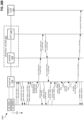
- FIG. 17 is a block diagram of an exemplary system operable to provide wireless service for a plurality of UEs 1052-1 - 1052-N (where "N” is simply intended to represent an integer greater than “1” and not necessarily equal to any other "N” reference designated herein).
- upstream and downstream links of an exemplary communication system offers high speed data services over connected devices, such as the modem 1022.
- the modem 1022 may be configured with or receive communications from the rSC 1032 so as to allow the UEs 1052 to communicate through the communication system in a manner that is transparent to the user.
- the communication system includes a communication component 4012 configured with an upstream hub 4202.
- the hub 4202 is coupled to a fiber node 4212 via optical communication links 4052 and 4062.
- the hub 4202 includes a Modem Termination System (MTS) 1062 an electrical to optical converter 403, and an optical to electrical converter 4042.
- MTS Modem Termination System
- the node 4212 is similarly configured with an optical to electrical converter 4082 and an electrical to optical converter 4072.
- the communication component 4012 is the source for various communication signals. Antennas may receive communication signals that are converted as necessary and transmitted over fiber optic cables 4052 to the hub 4202. Several hubs may be connected to a single communication component 401 and the hub 4202 may each be connected to several nodes 4212 by fiber optic cable links 4052 and 4062.
- the vMTS 1062 may be configured in the communication component 4012 or in the hub 4202.
- transmissions from the vMTS 1062 to the modem are carried over the downstream portion of the communication system generally in the band between 54 MHz and 3 GHz.
- Downstream digital transmissions are continuous and are typically monitored by many modems.
- Upstream transmissions from the modems to the vMTS 1062 are, for example, typically carried in the 5-600 MHz frequency band, the upstream bandwidth being shared by the Modems that are on-line. However, with greater demands for data, additional frequency bands and bandwidths are continuously being deployed in the downstream and upstream paths. It is also possible that modems and the MTS engage in full duplex transmission modes, whereby concurrent transmissions on the upstream and the downstream over the same frequency are supported.
- Equivalent communications and protocols for fiber optic transmissions are also contemplated, for example, using an optical network terminal (ONT) or optical line termination (OLT), and an optical network unit (ONU), and equivalent protocols such as EPON, RFOG, or GPON.
- the vMTS 1062 connects the system to the Internet backbone.
- the vMTS 106 connects to the downstream path through an electrical to optical converter 4042 that is connected to the fiber optic cable 4062, which in turn, is connected to an optical to electrical converter 4082 at the node 4212.
- the signal is transmitted to a diplexer 4092 that combines the upstream and downstream signals onto a single cable.
- the diplexer 409 allows the different frequency bands to be combined onto the same cable.
- the signal is may be carried by a coaxial cable 4302.
- a power inserter 4102 may be used to power the coaxial line equipment, such as amplifiers or other equipment.
- the signal may be split with a splitter 4112 to branch the signal. Further, at various locations, bi-directional amplifiers 4122 may boost and even split the signal. Taps 4132 along branches provide connections to subscriber's homes 4142 and businesses.
- Upstream transmissions from subscribers to the hub 4202/headend 4012 occur by passing through the same coaxial cable 4302 as the downstream signals, in the opposite direction on a different frequency band.
- the upstream signals may be sent typically utilizing Quadrature Amplitude Modulation (QAM) with forward error correction.
- QAM Quadrature Amplitude Modulation
- the upstream signals can employ QPSK or any level of QAM, including 8 QAM, 32 QAM, 64 QAM, 128 QAM, 256 QAM, 512 QAM, 1024 QAM, and 4096 QAM.
- Modulation techniques such as Synchronous Code Division Multiple Access (S-CDMA) and Orthogonal Frequency Division Multiple Access (OFDMA) can also be used. Of course, any type of modulation technique can be used, as desired.
- FIG. 18 is a block diagram of an exemplary wireless service link.
- the wireless service link may include a mediator 1013 in communication with an MTS 1063.
- mediator 1013 may be integrated with or communicatively coupled with MTS 1063.
- the MTS 1063 may be, for example, a CMTS, a Fiber Node, a Fiber Hub, an optical network unit (ONU), or other termination device.
- Mediator 1013 may be implemented, for example, as a software agent in any of such devices. If mediator 1013 is integrated with an MTS, integration may be via software or hardware.
- a UE 1053 may wirelessly communicate with other UEs (not shown) in a wireless service network for the purpose of transmitting and/or receiving data.
- a mobile core 1073 e.g., operated by an MNO
- subscription information e.g., data communication, data plans, roaming, international calling, etc.
- CSS processor 1093 Based on the intercepted setup information CSS processor 1093 initiates a backhaul communication session (also called a "communication session” herein) between the modem 1023 and the MTS 1063 to deliver the wireless session through the communication session. CSS processor 1093 initiates the communication session prior to, during, or close it time to when the wireless session is set-up such that the set-up process time, that of both the communication session and the wireless session, is reduced. In one embodiment, the set-up of the backhaul communication session and the wireless session occur at least partially in parallel, thereby reducing the set-up process time.
- a backhaul communication session also called a "communication session” herein
- the CSS 1043 may process the intercepted message and generate or otherwise provide data to MTS 1063 such that MTS 1063 may establish a communication session and a Quality of Service for the communication session between itself and the modem 1023. This may be done prior to, in parallel to, or close in time to the establishment of a wireless session by the mobile core 1073 with UE 1053, see below for more details.
- One or more of the components of the mediator 1013 and CSS 1043 may be integrated or in communication with the MTS 1063 via hardware, software, or combinations thereof.
- MNOs In the past, MNOs often maintained, operated, and controlled wireless base stations themselves for the purposes of providing communications with UEs.
- an MNO employing LTE communications may operate a plurality of eNodeBs in an area to provide wireless services to subscribing UEs in that area.
- MSOs are seeking to increase their value to the MNOs by providing alternative backhaul paths for communication between UEs, such as UE 1053, and the mobile core, such as mobile core 1073.
- MSOs and wireless operators currently employ wireless devices, a non-limiting example of which is small cell 1033, for capturing a wireless data transmission and passing it through a backhaul system, such as that shown in FIG. 18 .
- the backhaul system includes modem 1023, MTS 1063, and optionally meditator 1013.
- the small cell 1033 comprises many of the features of a larger base station such as the air-to-air interface and protocol handling.
- the small cell 1033 may be a multi-radio hotspot providing for Wi-Fi, as well as LTE Licensed Assisted Access (LTE-LAA) or LTE Unlicensed (LTE-U).
- LTE-LAA LTE Licensed Assisted Access
- LTE-U LTE Unlicensed
- communication is Wi-Fi communication and is between a STA (not shown) a Wi-Fi core (not shown).
- STA Wi-Fi station
- Wi-Fi core not shown
- the UE, small cell and mobile core exchange data sessions establishment with control signaling that includes QoS parameters.
- the QoS parameters describe a service quality for the data transmitted over the impending wireless session.
- the MTS 1063 and the modem 1023 need to establish a communication session that allows a wireless session between the UE 1053 and the mobile core 1073 to occur.
- QoE Quality of Experience
- the backhaul link between the MTS 1063 and the modem 1023 should have matching or similar QoS provisions as the QoS requirements exchanged between the UE 1053 and mobile core 1073.
- the QoS information contained in the LTE signaling is unknown by the backhaul system. Since the MTS 1063 and the modem 1023 are unaware of the underlying wireless traffic, the MTS 1063 and the modem 1023 do not know when a wireless session is being established. So, the MTS 106 and the modem 1023 cannot understand what types of Quality of Service (QoS) need to be employed. For example, in LTE, the mobile core 1073 may need to establish QoS parameters for the UE 1053 based on the subscription information of the UE 1053 and the type of media being requested by the application in use by the UE 1053.
- QoS Quality of Service
- LTE identifies QoS with a QoS Class Identifier (QCI), and can employ traffic prioritization such as Allocation and Retention Priority (ARP), a Guaranteed Bit Rate (GBR), a Maximum Bit Rate (MBR), an Access Point Name-Aggregate Maximum Bit Rate (APN-AMBR), a UE-AMBR, or some combination thereof.
- ARP Allocation and Retention Priority
- GRR Guaranteed Bit Rate
- MRR Maximum Bit Rate
- APN-AMBR Access Point Name-Aggregate Maximum Bit Rate
- UE-AMBR User Equipment-AMBR
- the MTS 1063 becomes aware of the QoS requirement for the session requested by either the UE 105, or the mobile core 1073, the time it takes to set up adequate QoS provisions between the MTS 1063 and the modem 1023 adds latency to the existing wireless session setup process. Consequently, the end user's wireless session start time is delayed due to the serial setup processes (e.g., due to serial setup procedure of LTE and DOCSIS sessions), and the user's OoE is still affected.
- the present embodiments provide for the backhaul QoS signaling (e.g., via a DOCSIS protocol) to be completed in parallel with the wireless session establishment (e.g., LTE wireless session establishment).
- the present embodiments therefore enable the backhaul system to become aware of the QoS requirement for the wireless traffic such that they provide for the provisioning of the wireless session(s) accordingly, as well as enables the provisioning process to occur without added latency.
- the MTS 1063 is configured to identify the various aspects of the wireless session.
- the MTS 1063 may include a mediator 1013 comprising functionality of a gateway.
- the MTS 1063 can intercept a request from the UE 1053 (e.g., via the CSS 1043) that indicates whether the UE 1053 needs to establish a session to transfer data to the mobile core 1073. This may direct the MTS 1063 to initiate the establishment of a communication session between the MTS 1063 and the modem 1023.
- the MTS 1063 may be configured with functionality of the mobile core 1073 to decode and interpret LTE messages.
- the MTS 1063 is a CMTS, and may include functionality of an LTE gateway that is operable to intercept a session establishment request from the UE 1053 indicating that it needs to start a wireless session to the mobile core 1073. This may direct the MTS 1063 to initiate the establishment of a communication session between the MTS 1063 and the modem 1023.
- the MTS 1063, mediator 1013, and/or CSS 10 3 may also intercept a response to the request from the mobile core 1073 (e.g., via mediator 1013 or CSS 1043). For example, when the mobile core 1073 receives a request from the UE 1053, the mobile core 1073 establishes the requested wireless session between the mobile core 1073 and the UE 1053. This may include establishing the parameters of the QoS for the wireless session. The MTS 1063 may intercept this information and initiate the setup of the communication session between the MTS 1063 and the modem 1023 using those QoS parameters for the wireless session to ensure that the user of the UE 1053 has an acceptable QoE.
- the MTS 106 and the modem 1023 work together to ensure that the QoS of the transport properly matches or supports the QoS of the wireless session.
- the MTS 106 and the modem 1023 do so without unnecessarily consuming or reserving too many network resources.
- the operator determines how the QoS mechanism is applied to support the QoS Class Identifiers (QCls), and configures these policy rules into the gateway, allowing the operator to optimize resources for QoS on their network.
- QoS Class Identifiers QoS Class Identifiers
- the mobile core 1073 may communicate out of band signaling (OOB) indicating that a wireless session between the mobile core 1073 and the UE 1053 is to be established.
- OOB out of band signaling
- the MTS 1063, mediator 1013, and/or CSS 1043 are operable to detect that signaling and initiate or participate in the establishment of a communication session between the MTS 1063 and modem 1023 to accommodate the wireless session.
- the communication session with the needed QoS can be established in parallel or at least partially in parallel to the wireless session rather than in series.
- some operators may use DOCSIS network for backhauling traffic of the mobile core 1073.
- DOCSIS and radio networks such as LTE, have separate scheduling algorithms that result in longer communication latencies. That is, a radio network schedules traffic from the UE 1053 differently than an MTS, such as an CMTS, schedules traffic from the modem 1023. This often results in the mobile core 107 needing to wait until the DOCSIS network completes a session establishment before the proper QoS session establishment can be completed.
- the UE 1053 is any device, system, software, or combination thereof operable to communicate wirelessly with a wireless network using any one or more wireless protocols including, 2G, 3G, 4G, 5G, LTE, LTE-U, LTE-LAA, or the like, as well as with a Wi-Fi network using any one or more wireless service protocols including 802.11 ax.
- Examples of the UE 1053 include, but are not limited to, laptop computers, tablet computers, and wireless telephones such as smart phones.
- the small cell 1033 is any device, system, software, or combination thereof operable to provide an air-to-air interface 1103 for the mobile core 1073, one example of which is a Wi-Fi core.
- Examples of the small cell 103 include Wi-Fi access points and base stations operating as eNodeBs in a wireless network.
- the modem 1023 is any device, system, software, or combination thereof operable to provide data transfers with an MTS.
- Examples of the modem 102 include DOCSIS enabled set-top boxes, a Optical Network Unit or fiber optic modem, and a satellite modem.
- the MTS 1063 is any device, system, software, or combination thereof operable to communicate with the modem 1023 as well as provide a wireless service session through the communication link provided by the modem 102 3and the MTS 1063.
- the CSS 1043 and its components may implement the functionality for establishing the communication session setup stated herein.
- the CSS 1043 may be any device, system, software, or combination thereof operable with or in the mediator 1013 and/or the MTS 1063 to implement said functionality.
- Other exemplary embodiments are shown and described below.
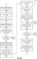
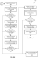
- FIG. 19 is a flowchart illustrating an exemplary process 2003 operable with the MTS 1063 of FIG. 18 .
- the small cell 103 communicates with the UE 1053 over the air-to-air interface 1103 and forwards any UE data to the modem 1023.
- the modem 1023 may forward the data to the MTS 1063.
- the CSS 104 receives the data, in the process element 2013, and determines whether the data includes a request for a wireless session, in the process element 2023.
- the CSS 1043 may evaluate all or a portion of the data from the UE 10533 and determine whether the UE 1053 is transmitting a request to the mobile core 1073 such that the mobile core 1073 can establish a wireless session with UE 1053.
- mediator 1013 which in is communication with MTS 1063, determines whether the data includes a request for a wireless session.
- the CSS 1043 simply forwards the data to the mobile core 1073 servicing the UE 1053, in the process element 2033, and process 2003 ends. If it is determined in process element 2023, the data from the UE 1053 does include a request to establish a wireless session, then the CSS 1043 forwards, or is optionally instructed by the mediator 1013 to forward, the request to the mobile core 1073, in the process element 2043.
- the CSS 104 may inspect traffic from the mobile core 1073 intended for the UE 1053. In this regard, the CSS 1043 may intercept setup information for wireless session from the mobile core 1073, in the process element 2053.
- the CSS 1043 propagates the setup information to the modem 1023 such that it may forward the setup information to the small cell 1033 and to the UE 1053 over the air-to air-interface 1103. This allows the mobile core 1073 to setup a wireless session with the UE 105.
- the CSS 1043 initiates a communication session between the MTS 106 and the modem 1023 based on the intercepted setup information, in the process element 2063.
- the MTS 1063 sets up its communication session with the modem 102 while the mobile core 107 is setting up its wireless session with the UE 1053, thereby reducing latencies associated with the differences between the wireless and wireline protocols.
- FIG. 20 is an exemplary communication diagram of the wireless service link of FIG. 18 .
- the small cell 1033 communicates with the UE 1053 over the air-to-air interface 1103 via a wireless protocol.
- the UE 1053 communicates via the wireless protocol.
- the application may request a new wireless session through the mobile core 1073. Accordingly, the UE 1053 transfers a bearer resource allocation request to the mobile core 1073 via the small cell 1033.
- the small cell 1033 forwards the request to the modem 1023.
- the modem 1023 forwards the request onto the MTS 1063 over the communication link.
- the MTS 1063 or an associated mediator 1013 may intercept the request (element 1203) and recognize it as a bearer resource allocation request from the UE 1053. This would allow the MTS 1063 or the associated mediator 1013, independently or cooperatively, to prepare for a response from the mobile core 1073 indicating that is about to establish a wireless session with the UE 1053.
- the MTS 1063 or the associated mediator 1013 (e.g., via the functionality of the CSS 1043), independently or cooperatively, forwards the request to the mobile core 1073 and waits for the associated response.
- a dedicated bearer context activation e.g., a Evolved Packet System (EPS) bearer context activation
- the MTS 1063 intercepts that activation message (element 1213) and processes all or a portion of the message to access to determine that the mobile core 1073 is establishing a wireless session with the UE 1053. Accordingly, the MTS 1063 extracts activation message data, such as but not limited to the QoS parameters, from the activation message.
- EPS Evolved Packet System
- the MTS 1063 does this to establish, for example, the same or compatible QoS parameters with the communication session between the MTS 1063 and the modem 1023. Then, the MTS 1063 establishes a communication session between the MTS 1063 and the modem 1023 (e.g., via a DOCSIS Dynamic Service Flow (DSx) message), as well as forwards the activation message to the small cell 1033, which in turn forwards it to the UE 1053. Thus, the MTS 1063 establishes the setup of communication session after or substantially at the same time the wireless session is finalized. Once the wireless session is established, wireless communications can commence between the UE 1053 and the mobile core 1073 because the communication session between the MTS 1063 and the modem 1023 has already been established.
- DSx DOCSIS Dynamic Service Flow
- the invention can take the form of an entirely hardware embodiment, an entirely software embodiment or an embodiment containing both hardware and software elements.
- Embodiments utilizing network functions virtualization (NFV) and virtualized hardware, such as a virtualized MTS, modem, etc., are also contemplated.
- the invention is implemented in whole or in part in software, which includes but is not limited to firmware, resident software, microcode, etc.
- FIG. 21 illustrates a computing system 3003 in which a computer readable medium 3063 may provide instructions for performing any of the methods disclosed herein.
- the invention can take the form of a computer program product accessible from the computer readable medium 3063 providing program code for use by or in connection with a computer or any instruction execution system.
- the computer readable medium 306 can be any apparatus that can tangibly store the program for use by or in connection with the instruction execution system, apparatus, or device, including the computer system 3003.
- the medium 3036 can be any tangible electronic, magnetic, optical, electromagnetic, infrared, or semiconductor system (or apparatus or device).
- Examples of a computer readable medium 3063 include a semiconductor or solid state memory, magnetic tape, a removable computer diskette, a random access memory (RAM), a read-only memory (ROM), a rigid magnetic disk and an optical disk.
- Some examples of optical disks include compact disk - read only memory (CD-ROM), compact disk - read/write (CD-R/W) and DVD.
- the computing system 3003, suitable for storing and/or executing program code can include one or more processors 3023 coupled directly or indirectly to memory 3083 through a system bus 3103.
- the memory 3083 can include local memory employed during actual execution of the program code, bulk storage, and cache memories which provide temporary storage of at least some program code in order to reduce the number of times code is retrieved from bulk storage during execution.
- I/O devices 3043 can be coupled to the system either directly or through intervening I/O controllers.
- Network adapters may also be coupled to the system to enable the computing system 3003 to become coupled to other data processing systems, such as through host systems interfaces 3123, or remote printers or storage devices through intervening private or public networks. Modems and Ethernet cards are just a few of the currently available types of network adapters.
- FIG. 22 is a block diagram of an exemplary system operable to provide wireless service for a plurality of UEs 1053-1 - 1053-N (where "N” is simply intended to represent an integer greater than “1” and not necessarily equal to any other "N” reference designated herein).
- upstream and downstream links of the exemplary communication system offers high speed data services over connected devices, such as the modem 1023.
- the modem 1023 may be configured with or receive communications from the small cell 1033 so as to allow the UEs 1053 to communicate through the communication system in a manner that is transparent to the user.
- the communication system includes a communication component 4013 configured with an upstream hub 4203.
- the hub 4203 is coupled to a fiber node 4213 via optical communication links 4053 and 4063.
- the hub 4203 includes an MTS 1063, an electrical to optical converter 4033, and an optical to electrical converter 4043.
- the node 4213 is similarly configured with an optical to electrical converter 4083 and an electrical to optical converter 4073.
- communication system 1004 includes User Equipment (UEs) 1024(1)-1 024(n), a small cell 1104, a backhaul system 1204 configured with a modem 1224 and a modem terminal system (MTS) 1244, and a wireless core 1304 (hereinafter core 1304).
- UEs 1024(1) - 1024(n) may be any user equipment or radio terminal, such as cell phones, laptop computers, tablet computers, wearables, Internet of Things (IoT) devices, a wireless equipped motor vehicle, etc.
- small cell 1104 may be any wireless access base station, for example, an eNodeB, a Wi-Fi access point, etc.
- the invention in total or in part, may take the form of an entirely hardware implementation, an entirely software implementation or an embodiment containing both hardware and software elements.
- Embodiments utilizing network functions virtualization (NFV) and virtualized hardware such as a virtualized MTS, virtualized modem, virtualized aspects of the MTS and/or modem, etc., are also contemplated.
- the invention is implemented in whole or in part in software, which includes but is not limited to firmware, resident software, microcode, etc.
- FIG. 26A is a detailed view of some aspects of the prioritized grant assignment system of FIG. 25 .
- System 1004 of FIG. 26 is described here processing multiple buffer status reports (BSRs) 2264 to generate a bulk request (REQ) 2704 for resources from a connected backhaul system 1204, in an embodiment.
- BSRs buffer status reports
- REQ bulk request
- Each UE 1024(1)-(n) is configured with an input/output (IO) system 2024, a CPU 2044, a wireless transceiver 2064, and a memory 2204, all of which are communicatively coupled. More or fewer components may be incorporated within a UE 1024 without departing from the scope herein.
- I/O 2024 may be any device level input/output system, including but not limited to a keyboard, mouse, touch screen, display, tactic feedback system, monitors (e.g., heart rate, Global Positioning (GSP), activity sensor, accelerometer, any health monitoring system, position sensors as used in room scale virtual reality (VR), etc.), graphics cards, sound card, I/O chips and/or chip sets, etc.
- GSP Global Positioning
- VR room scale virtual reality
- I/O 2024 may also be removably and/or temporality coupled with UE 1024.
- Processor 2044 may be a processing unit including but not limited to one or more of a central processing unit, a microprocessing unit, a graphics processing unit (GPU), a multi-core processor, a virtual CPU, a control unit, an arithmetic logic unit, a parallel processing unit or system, etc.
- Transceiver 2064 may be any or a plurality of wireless transceivers capable of wirelessly communication with the small cell 1104 on one or more compatible wireless communication protocols.
- Memory 2204 may be any non-transitory memory. Memory 2204 may also be a plurality of cooperative memory components. Memory 2204 may be implemented as or include one or more buffers. However memory 2204 is organized BSR 2264 describes at least a portion of it for purposes of requesting resources from one or more networks to transmit data stored therein.
- Memory 2204 stores at least a buffer status report (BSR) 2264, a data 2244 for transmission across backhaul system 1204 to core 1304, and one or more wireless grants 2224.
- BSR 2264(1), data 2244(1), and wireless grant 2224(1) are specific to UE 1024(1) and BSR 2264(n), data 2244(n), and wireless grant 2224(n) are specific to UE 1024(n) and may be erased, written over, or moved to a secondary storage device (not shown) at a time determined by UE 1024 or any decision making units within system 1004, such as modem 1224, MTS 1244, and core 1204.
- Wireless grants 2224(1) and 2224(n) are shown in dashed line to represent that they are only present after BSRs 2264(1) and 2264(n) are sent to and processed by small cell 1104, which generates wireless grants 2224(1) and 2224(n) and transmits them back to UEs 1024(1) and 1024(n), respectively. This process may be seen at least in FIGs. 28A-B .
- Downstream transceiver 2564 may be any of, or a plurality of, wireless transceivers capable of wirelessly communication with the UEs 1024(1)-(n) and other devices utilizing one or more compatible wireless communication protocols.
- Upstream transceiver 2574 is shown as a wireline communication unit.
- upstream transceiver 2574 may be a wireless transceiver for communicatively coupling with backhaul system 1204, for example to modem 1224.
- Upstream transceiver 2574 utilizes a backhaul 1204 compatible communication protocol.
- small cell 1104 may translate, repackage, and/or reorganize data received from one or more of UEs 1024(1)-(n) into one or more backhaul compatible data units or streams.
- the present system and method may translate, repackage, and/or reorganize the data in concert with the present prioritized grant assignment system and method.
- Bulk REQ module 2594 combines each BSR 2264(1)-(n) received from UEs 1024(1)- (n) into a single BSR, a bulk REQ 2704, for transmission to backhaul system 1204's MTS 1244 which results in a backhaul grant to modem 1224, discussed later. This ensures the backhaul system 1204 is prepared to forward all or a portion of data 2244(1)-(n) upon receipt at modem 1224.
- MTS 1244 processes bulk REQ 2704 and, based on network parameters such as available capacity, rate limits based on Service Level Agreements for the UEs being serviced on the small cell, or prioritization of traffic of the small cell compared to other small cells provides small cell 1104 a grant that accommodates all or a portion of the request for resources defined by bulk REQ 2704.
- FIGs. 27 and 28A describe an instance where processing bulk REQ 2704 results in a grant that completely satisfies the request.
- FIG. 28B describe an instance where processing bulk REQ 2704 results in a grant that partially satisfies the request.
- FIG. 26A The remaining description for FIG. 26A will focus on UE 1024(1), although it will be understood that the description is equally relevant to any of UEs 1024(2) - 1024(n).
- UE 1024(1) is shown having data 2244(1), which is ready for transmission to core 1304, stored in memory 2204(1).
- BSR 2264(1) is also stored in memory 2204, describes data 2244.
- BSR 2264(1) describes the amount of data in data 2244, e.g., A bytes of data.
- BSR 2264(1) may describe the amount of data in each LCG0 - LCG3.
- Bulk grant 2804 may accommodate all or a portion of the data within data 2244(1)-(n), depending on network resources available. As described above, this ensures the backhaul system 1204 is prepared to forward the allotted amount of data 2244(1)-(n) upon receipt at modem 1224. Small cell 1104 processes bulk grant 2804 to ascertain the resources available to it.
- modem 1224 may by formed with I/O 2524, CPU 2544, downstream transceiver 2564, upstream transceiver 2574, priority processor 2584, bulk request (REQ) module 2594, and memory 2604 such that modem 1224 performs the operations described above and below with modification that would be obvious to the skilled artisan. It will be understood that such an embodiment does not preclude modem 1224 from being a virtualized modem 1224, in whole or in part. Furthermore, it will be understood that a small cell 1104 implementation does not preclude small cell 1104 from also being a virtualized at least in part.
- FIG. 26B shows system 1004 of FIG. 26A after the receipt of wireless grant 2224(1) and 2224(n) at UES 1024(1) and 1024(n), respectively, and bulk grant 2804 at small cell 1104. Furthermore, system 1004 of FIG. 26B is shown transmitting data 2244(1) and (n) from UEs 1024(1) and 1024(n) to small cell 1104. Data 2244(1) and 2244(n) are stored in memory 2604. Because bulk grant 280 is in place when data 2244(1)-(n) arrives at small cell 1104 all or a portion of that data, depending on the grant, may be transmitted to core 1304 vie backhaul system 1204.
- bulk grant 2804 can accommodate all of data 2244(1) and 2244(n), that is A bytes + B bytes, then no further processing is requires and data 224(1) - 2244(n) is transmitted to core 1304 via backhaul system 1204 utilizing standard methods of repackaging or translating wireless data 2244(1) - 2244(n) in to a backhaul compatible container or data.
- priority process 258 acts on data 2244(1)-2244(n), discussed in more detail in at least FIG. 27 .
- FIG. 27 shows one exemplary priority processing module 2584 configured within small cell 1104, which processes upstream data for transmission after the receipt of bulk grant 2804, which is only a partial grant.
- Priority module 2584 is shown including a priority processor 3004 and a prioritized data-grant fit module 3204. Priority processing 2584, priority processor 3004, and prioritized data-grant fit module 3204 may be implemented as a single combined device or component, as standalone devices, or may be implemented, separately or together, as functionality executed by CPU 2544.
- Priority processor 3004 is represented to include a logical channel (LC) grouper 3044 and LCG0 3064 - LCG3 3094.
- LC logical channel
- LCG0 3064 is a buffer or temporary data storage for UE 1024(1) - 1024(n)'s LCG0 data.
- LCG1 3074 is a buffer or temporary data storage for UE 1024(1) - 1024(n)'s LCG1 data.
- LCG2 3084 is a buffer or temporary data storage for UE 1024(1) - 1024(n)'s LCG2 data.
- LCG3 3094 is buffer or temporary data storage for UE 1024(1) - 1024(n)'s LCG3 data.
- LC grouper 3044 takes all data 2244 at its input and stores, copies or otherwise records each UE 1024's LCG data into the appropriate LCG0 3064 - LCG3 3094 temporary storage. For example, LC grouper 304 process data 224(1) and data 2244(n) and copies all LCG0 data to LCG0 3064. That is, LC grouper 3044 copies data 2244(1)'s LCG0_1 data and data 2244(n)'s LCG_N data in LCG0 3064.
- LC grouper 3044 similarly copies all data 2244(1)'s and data 2244(n)'s LCG1 data to LCG1 3074, all data 2244(1)'s and data 2244(n)'s LCG2 data to LCG2 3084, and all data 2244(1)'s and data 2244(n)'s LCG3 data to LCG3 3094.
- CLG0 3064-LCG3 3094 are then copied to prioritized data-grant fit 3224 as LCG0 3364-LCG3 3394.
- Prioritized data-grant fit module 3224 is shown to be configured with a memory 3244, an upstream fit calculator (UFC) 3264, and a transmit buffer 3284.
- Memory 3244 has stored with in it bulk grant 2804 which was generated by MTS 1244, and LCG0 3364-LCG3 3394.
- Bulk grant 2804 of FIG. 27 is a grant for an amount of data equal to C+D bytes of data, which is a portion of that requested, namely A+B bytes of data.
- C+D bytes of data and A+B bytes of data are symbolically represented in transmit buffer 3284, more on this below.
- Transmit buffer is shown including LCG0_1, LCG0_N, LCG1_1, LCG1_N, LCG2_1, LCG2_N, LCG3_1, and LCG3_N.
- the size of LCG0_1, LCG0_N, LCG1_1, LCG1_N, LCG2_1, LCG2_N, LCG3_1, and LCG3_N is equal to A+B bytes, the size of the bulk REQ 270.
- the size of LCG0_1, LCG0_N, LCG1_1, LCG1_N, LCG2_1, and LCG2_N is equal to C+D bytes, the size of the bulk grant 2804. C+D ⁇ A+B.
- UFC 3264 takes as inputs bulk grant 2804 and LCG0 3364, LCG1 3374, LCG2 3384, and LCG3 3394. UFC 3264 then process the LCG0 3364, LCG1 3374, LCG2 3384, LCG3 3394 data, and bulk grant 2804 to determine which data can be accommodated by bulk grant 2804 for the related transmission. This process may be as simple as determining the size of bulk grant 2804 (C+D bytes) and perform arithmetic calculations to with LCG0, LCG1, LCG2, LCG3 in order of priority to determine which data packages can be accommodated by the bulk grant 2804.
- Another exemplary process is a UE prioritization process, which may order LCG data based on Service Level Agreement or priority, such that if C+D bytes of data provided by bulk grant 4804 is not sufficient to serve all UE logical channel group data, then LCG data is prioritized by UEs such that higher priority UEs have their data accommodated first.
- UE prioritization may be multi-tiered such that LCG0 data from first priority UEs are handled first, then LCG0 data from second priority UEs are handled next, and so forth.
- LCG1 data originating from a highest priority UE is handled before LCG0 data from a second tier UE.
- Determining the priority of UEs may be based on the type of device (e.g., emergency services devices autonomous vehicles have a higher priority than standard user devices and loT devices), a user or user account associated with the device (e.g., a business or premium account versus an individual account or lower tier account, or military account versus a civilian account), order of association with the small cell, etc. Other processes are detail below.
- type of device e.g., emergency services devices autonomous vehicles have a higher priority than standard user devices and loT devices
- a user or user account associated with the device e.g., a business or premium account versus an individual account or lower tier account, or military account versus a civilian account
- Other processes are detail below.
- bulk grant 2804 may accommodate C+D bytes of data, which provides for the transmission of LCG0_1, LCG0_N, LCG1_1, LCG1_N, LCG2_1, and LCG2_N over backhaul system 120.
- LCG3_1 and LCG3_N may be shifted the next or subsequent bulk request and upstream transmission.
- LCG3_1 and LCG3_N may be dropped, for example, if that data is determined to be stale.
- FIG. 28A is a communication diagram 4004 for system 1004 in the situation where all of a request conveyed by a Bulk REQ 2704 is granted, in an embodiment.
- two UEs are shown, UEs 1024(1) and 1024(n).
- FIG. 28A is best understood when read in combination with FIGs. 26A-B and 27 .
- UEs 1024(1) and 1024(n) transmit service requests (SRs) SR1 UE1 4024 and SR2 UE2 4044 to small cell 1104 to request a grant for the transmission of each UEs buffer status report (BSR), BSR 2264(1) and BSR 2264(n), see FIGs. 26A , 26B , and 3 .
- Small cell 1104 receives and processes SR1 UE1 4024 and SR2 UE2 4044, producing two BSR grants, BSR Grant UE1 4064 and BSR Grant UE2 4084, which are sent back to the respective UE.
- UE 1024(1) and 1024(n) receive and process the BSR grants 4064, 4084 and transmit BSR 2264(1) and BSR 2264(n).
- BSR 2264(1) conveys to small cell 1104 that UE 1024(1) has A bytes of data in its buffer
- BSR 2264(n) conveys to small cell 1104 that UE 1024(n) has B bytes of date in its buffer.
- a and B which describe the A and B bytes of data, are numeric variables which designate the size or amount of data stored in the respective buffers.
- Small cell 1104 processes BSR 2264(1) a4nd 2264(n) and produces a grant for each UE 1024, grant 2224(1) and grant 2224(n). In addition, small cell 1104 generates bulk REQ 2704.
- Bulk REQ 2704 is a request for backhaul system 1204 resources to transmit the combination of at least data 2244(1) and 2244(n) (or any data 2244(1)-(n) if more UEs 1104 are associated with small cell 1104 and have data in their buffers to transmit).
- Small cell 1104 transmits grants 2224(1) and 2224(n) to UEs 1024(1) and 1024(n), respectively, and bulk REQ 2704 to MTS 1244 via modem 1224 within backhaul system 1204.
- the order the UE Grants 2224 and the bulk REQ 2704 are produced and transmitted by small cell 1004 may vary according to implementation as long as they occur substantially close enough in time such that a bulk grant, one example of which is bulk grant 2804 as shown in FIGs.
- 26B , 27 and 28A may be received and processed by small cell 1104 prior to the receipt of data from the UEs, such as data 2244(1)-(n) discussed in more detail below.
- data 2244(1)-(n) discussed in more detail below.
- bulk grant 2804 is received at small cell 1104 after the receipt of data 2244(1) and 2244(n) at small cell 1104 as long as it is not so long after that there is no reduction in latency over the serial grant assignment utilized in the prior art.
- UE 1024(1) and UE 1024(n) prepare data 2244(1) and 2244(n), respectively, for transmission.
- UEs 1024(1) and 1024(n) also include new BSRs in data 2244(1) and 2244(n), shown in diagram 4004 as BSR_A and BSR_B.
- grants 2224(1) and 2224(n) include additional resources to accommodate BSR_A and BSR_B.
- BSR_A and BSR_B are requests for resources to transmit new data in UE 1024(a) and 1024(n)'s buffers that was generated after the transmission of SR1 UE1 4024 and SR2 UE2 4044. This "piggy backing" process reduces the need to go through the SR/BSR-grant process (described above) for the next and potentially subsequent data transmissions.
- small cell 1104 Upon receipt of data 2244(1) and 2244(n) and bulk grant 2804 at small cell 1104 the small cell packages 4124 data 2244(1) and 2244(n), for example in a manner similar to that shown and described for FIG. 27 , for transmission to core 1304 via backhaul system 1204. In an embodiment that includes BSR_A and BSR_B, small cell 1104 may also process BSR_A and BSR_B in a similar fashion as described above for BSR 2264(1) and 2264(n), producing new grants 4224(1) and 4224(n) and a second bulk REQ 4704.
- This second bulk REQ 4704 may be transmitted separately from (as shown in FIG. 28 ) or packaged with the upstream transmission of data 2244(1) and 2244(n) (not shown) to MTS 2244 on its way to core 1304. If second bulk REQ 4704 is transmitted separately from the upstream transmission of data 224(1) and 2244(n) to core 1304, as shown is in FIG. 28 , then BSR_A and BSR_B may be processed before or after the upstream transmission of data 2244(1) and 2244(n) from small cell 1104 to core 1304.
- Bulk REQ 4704 may be packaged with data 2244(1) and 2244(n) such that MTS 1244 can only read bulk REQ 4704, which utilizes a backhaul 1204 format or protocol, and MTS 1244 may not read data 2244(1) and 2244(n), which utilizes a core 1304 format or protocol different from that of backhaul 1204's format or protocol.
- FIG. 28B is a communication diagram 4504 for the present grant assignment process wherein only a portion of the request conveyed by a Bulk REQ is granted, in an embodiment.
- Bulk grant 4804 is transmitted to small cell 1104 via modem 1224. Substantially concurrently to the transmission and processing of bulk REQ 2704 and generation of bulk grant 4804, UEs 1024(1) and 1024(n) process grants 2224(1) and 2224(n), prepare data 2244(1) and 2244(n) and optionally new BSRs BSR_A and BSR_B, and transmits these to small cell 110, as similarly described from diagram 4004, FIG. 28A .
- small cell 1104 performs a logical channel grouping process ad prioritized grant fit process as described in FIG. 27 . That is, the priority processor 3004 groups together all LCG 0 data from each UE 1024's data 2244, all LCG1 data from each UE 1024's data 2244, etc.
- the prioritized data-grant fit 3224 unit the fits the LCG data to the bulk grant 2804, 4804 such that data with the highest priority, LCG0 Data, is prioritized for transmission, followed by LCG1, LCG2, etc.
- LCG3_1 and LCG3_N data are subsequently retained in the transmit buffer 3284, memory 2640, or a similar generic or dedicated memory, which may or may not be shown.
- small cell 1104 may also process new BSRs, BSR_A and BSR_B, and provide grants 4224(1) and 4224(n) to UEs 1024(1) and 1024(n).
- FIGs. 29A-C describe a method 5004 detailing one exemplary process for generating a bulk request for resources, in an embodiment.
- FIGs. 29A-C are best viewed together.
- Step 5024 of method 5004 receives an SR1 and an SR2 from UE1 and UE2, respectively.
- An example of step 5024 is UEs 1024(1) and 1024(n) transmitting SR1 UE1 4024 and SR2 UE2 4044 to small cell 1104, as shown and described in FIGs. 28A and 28B .
- Step 5044 of method 5004 sends a BSR Grant to both UE1 and UE2.
- An example of step 5044 is small cell 1104 transmitting BSR grant UE1 4064 and BSR grant UE2 4084 to UE 1024(1) and UE 1024(n), respectively.
- Optional step 5064 of method 5004 determines what resources are available to small cell in preparation for processing the forthcoming BSRs from the UEs.
- An example of step 5064 is small cell 1104 analyzing its available resource for comparison to the BSRs received from UEs 1024(1) and 1024(n) in step 5084 - 5104.
- Step 5084 of method 5400 receives BSR1 and BSR2 from UE1 and UE2, respectively.
- An example of step 5084 is small cell 1104 receiving BSR 2264(1) and 2264(n) from UEs 1024(1) and 1024(n), respectively.
- Optional step 5104 of method 5004 compares the optional step 5064 determined available resources to the step 5084 received BSRs (BSR1 and BSR2) to determine if the small cell has resources to accommodate the UE requests.
- An example of step 5104 is small cell comparing its predetermined available resources with the received BSRs 2264(1) and 2246(n) to determine if resources are available and when they are available.
- Step 5124 of method 5004 determines if and when resources are available to accommodate the BSRs. If resources are available method 5004 moves to step 5144. If resources are not available, method 5004 moves to step 5424 of FIG. 29B , described below.
- An example of step 5124 is small cell 1104 producing a result as to the available resources and acting on that result by initiating either the process of step 5144 or 5404, FIG. 29B .
- Step 5144 of method 5004 generates a UE1 Grant and a UE2 Grant to accommodate all data requested by BSR1 and BSR2.
- An example of step 5144 is small cell 1104 producing a grant 2224(1) for UE 1024(1) and a grant 2224(n) for UE 1024(n).
- Step 5164 of method 5004 combines all grants, e.g., UE1 grant and UE2 grant, to generate a bulk backhaul request and transmits the bulk backhaul request to the processing aspect of the backhaul system.
- An example of step 5164 is small cell 1104 combining grants 2224(1) and 2224(n) as described, for example, in FIGs. 27 and 28A and 4B, to produce and transmit bulk REQ 270 to MTS 1244 via modem 1224. It will be understood that other backhaul components may be involved in the process, for example, if alternative backhaul systems are used, e.g., any backhaul system that relies on a request grant protocol.
- Step 5184 of method 5004 sends UE1 grant to UE1 and UE2 grant to UE2.
- An example of step 5184 is small cell 1104 transmitting grant 2224(1) and 2224(n) to UE 1024(1) and 1024(N), respectively.
- Step 5204 of method 5004 receives bulk grant from backhaul system.
- An example of step 5204 is MTS generating a bulk grant 2804 is then received by small cell 1104 from MTS 1244 via modem 1224.
- Step 5224 of method 5004 receives UE1 and UE 2 data and optionally receive a second BSR1 from UE1 and a second BSR2 from UE2.
- An example of step 5204 is small cell 1104 receiving data 2244(1) and 2244(n) from UEs 1024(1) and 1024(n), respectively.
- small cell 1104 may also receive a new BSR from UE 1024(1), BSR_A, and a new BSR from UE 1024(n), BSR_B.
- Step 5244 of method 5004 process bulk grant and bulk request to determine if the bulk grant accommodates all of UE1 and UE 2 Data.
- An example of step 5224 is small cell 1004 determining if the bulk grant received in step 5204 satisfies the bulk REQ 2704, sent is step 5164.
- Step 5264 of method 5004 provides a decision based on the results of step 5244, determining if the bulk grant accommodates all of UE1 and UE 2 Data. If it is determined that the bulk grant does not accommodate all of the data described in the bulk request, decision method 5004 moves to step 5504 of FIG. 29C , described further below. If step 5264 determines that the bulk grant satisfies the bulk request, then method 5004 moves to step 5284.
- An example of step 5244 is small cell 1104 processing the result of a comparison between the bulk grant and the bulk request.
- Step 5284 of method 5004 groups UE1 data and UE2 data for transmission to the mobile core via backhaul system.
- One example of step 5284 is small cell 1104 packaging data A+B 412, as described in FIG. 28A .
- Step 5304 of method 5004 transmits UE1 Data and UE2 Data to the Mobile Core via the Backhaul system.
- One example of step 530 is small cell 110 transmitting data 2244(1)+2244(n) to mobile core via modem 2224, MTS 2244, and core 1304, as described in FIG. 28A .
- FIG. 29B shows a method 5404, which branches from step 5124 of method 5004, FIG. 29A , for handling a partial small cell grant.
- step 5424 method 5404 generate a UE1 and UE2 partial grant to accommodate a portion of the request resources as described in BSR1 and BSR2.
- One example of step 5424 is small cell processing the results of step 506 and BSR 2264(1) and BSR 2264(n) to generate a partial grant for BSR 2264(1) and a partial grant for BSR 2264(n).
- step 5444 method 5404 combines UE1 and UE2 partial grants to generate bulk request and transmits the bulk request to the backhaul system for processing.
- One example of step 5444 is small cell 1104 combining partial grants (not shown) to produce a bulk request, similar to bulk REQ 2704, and transmitting it to MTS 1244 via modem 1224.
- Step 5464 method 5404 transmits the partial grants, generated in step 5424, to UE1 UE2.
- One example of step 5464 is small cell 1104 transmitting partial grants, similar to grants 2224(1) and 2224(n), to UEs 1024(1) and 1024(n).
- step 5484 method 5404 receives a bulk grant from the backhaul system.
- Noe example of step 5484 is small cell 1104 receives a bulk grant, similar to bulk grant 2804 of FIG. 28A , from MTS 1244 via modem 1224.
- step 5504 method 5404 receive data and optionally new BSRs from the UEs.
- One example of step 5504 is small cell 1104 receiving data, similar to data 2244(1) and 2244(n) from UEs 1024(1) and 1024(n). Method 5404 then moves to step 5244 of FIG. 28B .
- FIG. 29B shows a method 5604, which branches from step 5264 of method 5004, FIG. 29A , for handling a partial backhaul grant.
- step 5624 method 5604 performs a logical channel grouping by grouping together all UE data by Logical Channel Group (LCG) such that, for example, all UE1-UEn data designated as Logical Channel Group 0 (LCGO) are grouped together, all UE1-UEn data designated as Logical Channel Group 1 (LCG1) are grouped together, etc.
- LCG Logical Channel Group
- step 5624 LC grouper 3044 taking in data 2244(1) and 2244(n) and placing LCG0_1 data with LCG0_n data in LCG0 3064, placing LCG1_1 data with LCG1_n data in LCG1 3074, placing LCG2_1 data with LCG2_n data in LCG2 3084, placing LCG3_1 data with LCG3_n data in LCG3 3094, as described in FIGs. 27 and 28B .
- metadata describing LCG0-LCG3 may be grouped together or otherwise organized for analysis in the later steps of method 5604 to determine what LCG data the grant may accommodate.
- step 5644 method 5604 performs an upstream fit calculus by analyzing if the bulk grant can accommodate the LCG0 data. Method 5604 then moves to decision step 5664 where method 5604 makes a decision based on the result of step 5644. If the bulk grant cannot accommodate all of the LCG0 data then method 5604 moves to step 5904, where method 5604 buffers any un-accommodated LCG data for later transmission.
- method 5604 may perform a second analysis (not shown) to determine if the bulk grant can accommodate LCG0 data from a UE in order of priority. For example, UE1 (e.g., a medical device) may have a higher priority than UE2 (e.g., a gaming device) such that if the bulk grant cannot accommodate all of LCG0 data (e.g., UE1 LCG0 data plus UE2 LCG0 data) then method 5604 may determine if the bulk grant can accommodate LCG0 data from high priority UE1 only.
- UE1 e.g., a medical device
- UE2 e.g., a gaming device
- method 5604 moves UE2 LCG0 data to step 5904, buffering it for later transmission and UE1 LCG0 data is moved through the rest of method 5604 or just prepared for transmission if the bulk grant cannot accommodate any other data.
- step 5664 If it is determined in step 5664 that the bulk grant can accommodate all of the LCG0 data then decision step 5664 moves to step 5674.
- step 5674 prepares the LCG0 data for transmission.
- One example of step 5674 is LCG0_1 and LCG0_n data sent to transmit buffer 3284, FIG. 27 .
- step 5684 method 5604 performs an upstream fit calculus by analyzing if the bulk grant can accommodate the LCG1 data. Method 5604 then moves to decision step 5704 where method 5604 makes a decision based on the result of step 5684. If the bulk grant cannot accommodate all of the LCG1 data then method 5604 moves to step 5904, where method 5604 buffers any un-accommodated LCG data for later transmission. If it is determined in step 5704 that the bulk grant can accommodate all of the LCG1 data then decision step 5704 moves to step 5714.
- step 5714 method 5604 prepares the LCG1 data for transmission.
- step 5724 method 5604 performs an upstream fit calculus by analyzing if the bulk grant can accommodate the LCG2 data. Method 5604 then moves to decision step 5744 where method 5604 makes a decision based on the result of step 5724. If the bulk grant cannot accommodate all of the LCG2 data then method 5604 moves to step 5904, where method 5604 buffers any un-accommodated LCG data for later transmission. If it is determined in step 5744 that the bulk grant can accommodate all of the LCG1 data then decision step 5744 moves to step 5754.
- step 5754 prepares the LCG2 data for transmission.
- One example of step 5754 is LCG2_1 and LCG2_n data sent to transmit buffer 3284, FIG. 27 .
- step 5764 method 5604 performs an upstream fit calculus by analyzing if the bulk grant can accommodate the LCG3 data. Method 5604 then moves to decision step 5784 where method 5604 makes a decision based on the result of step 5764. If the bulk grant cannot accommodate all of the LCG3 data then method 5604 moves to step 5904, where method 5604 buffers any un-accommodated LCG data for later transmission. If it is determined in step 5784 that the bulk grant can accommodate all of the LCG3 data then decision step 5784 moves to step 579.4
- step 5794 method 5604 prepares the LCG3 data for transmission.
- One example of step 5794 is LCG3_1 and LCG3_n data sent to transmit buffer 3284, FIG. 27 .
- step 5804 all data that can be accommodated by the bulk grant is sent, via the backhaul system to its destination, e.g., a mobile or Wi-Fi core.
- the method and associated system may package any buffered un-accommodated data such that the packaged data may be easily added to a forth coming backhaul bulk request.
- the method and associated system may also monitor the portions of data within the buffered un-accommodated data to determine if any of that data has become "stale.” Any stale data may be removed and the remaining data may be repackaged so it may be added to any forth coming backhaul bulk request.
Landscapes
- Engineering & Computer Science (AREA)
- Computer Networks & Wireless Communication (AREA)
- Signal Processing (AREA)
- Quality & Reliability (AREA)
- Mobile Radio Communication Systems (AREA)
Applications Claiming Priority (11)
| Application Number | Priority Date | Filing Date | Title |
|---|---|---|---|
| US201662306360P | 2016-03-10 | 2016-03-10 | |
| US201662339463P | 2016-05-20 | 2016-05-20 | |
| US201662345634P | 2016-06-03 | 2016-06-03 | |
| US201662353755P | 2016-06-23 | 2016-06-23 | |
| US201662357770P | 2016-07-01 | 2016-07-01 | |
| US15/236,147 US10492104B2 (en) | 2016-03-10 | 2016-08-12 | Latency reduction in wireless service |
| US15/447,419 US10321351B2 (en) | 2017-03-02 | 2017-03-02 | System and method for grant assignment |
| US15/453,146 US10237786B2 (en) | 2016-03-10 | 2017-03-08 | Latency reduction for virtualized small cells |
| US15/454,668 US11064393B2 (en) | 2016-03-10 | 2017-03-09 | Systems and methods for expedited session setup of a wireless session |
| PCT/US2017/021918 WO2017156463A1 (en) | 2016-03-10 | 2017-03-10 | Systems and methods for latency reduction |
| EP17764235.2A EP3427514B1 (en) | 2016-03-10 | 2017-03-10 | Methods for latency reduction |
Related Parent Applications (2)
| Application Number | Title | Priority Date | Filing Date |
|---|---|---|---|
| EP17764235.2A Division-Into EP3427514B1 (en) | 2016-03-10 | 2017-03-10 | Methods for latency reduction |
| EP17764235.2A Division EP3427514B1 (en) | 2016-03-10 | 2017-03-10 | Methods for latency reduction |
Publications (3)
| Publication Number | Publication Date |
|---|---|
| EP4007423A1 EP4007423A1 (en) | 2022-06-01 |
| EP4007423C0 EP4007423C0 (en) | 2024-12-18 |
| EP4007423B1 true EP4007423B1 (en) | 2024-12-18 |
Family
ID=59790820
Family Applications (2)
| Application Number | Title | Priority Date | Filing Date |
|---|---|---|---|
| EP21213978.6A Active EP4007423B1 (en) | 2016-03-10 | 2017-03-10 | Methods for latency reduction |
| EP17764235.2A Active EP3427514B1 (en) | 2016-03-10 | 2017-03-10 | Methods for latency reduction |
Family Applications After (1)
| Application Number | Title | Priority Date | Filing Date |
|---|---|---|---|
| EP17764235.2A Active EP3427514B1 (en) | 2016-03-10 | 2017-03-10 | Methods for latency reduction |
Country Status (7)
| Country | Link |
|---|---|
| US (3) | US11330476B2 (OSRAM) |
| EP (2) | EP4007423B1 (OSRAM) |
| JP (1) | JP2019511866A (OSRAM) |
| KR (1) | KR102149822B1 (OSRAM) |
| CN (1) | CN109076413B (OSRAM) |
| CA (1) | CA3017210C (OSRAM) |
| WO (1) | WO2017156463A1 (OSRAM) |
Families Citing this family (12)
| Publication number | Priority date | Publication date | Assignee | Title |
|---|---|---|---|---|
| CA3017210C (en) * | 2016-03-10 | 2024-02-13 | Cable Television Laboratories, Inc. | Systems and methods for latency reduction |
| US12225536B2 (en) | 2016-10-07 | 2025-02-11 | Cable Television Laboratories, Inc. | System and method for grant assignment |
| US11470634B2 (en) * | 2018-01-18 | 2022-10-11 | Intel Corporation | Apparatuses, devices and methods for a wireless network access device, a network gateway device, a wireless communication device and for a network device |
| JP6760982B2 (ja) * | 2018-02-05 | 2020-09-23 | ソフトバンク株式会社 | 無線中継装置及び通信システム |
| WO2019170209A1 (en) * | 2018-03-05 | 2019-09-12 | Nokia Technologies Oy | Methods and apparatuses to estimate and exchange latency and/or reliability information for dual or multi connectivity operation |
| US11507082B2 (en) * | 2019-03-26 | 2022-11-22 | Toyota Jidosha Kabushiki Kaisha | Quality of experience (QoE) management for vehicle control systems |
| CN113260071B (zh) * | 2020-02-13 | 2023-06-23 | 维沃移动通信有限公司 | Bsr汇报方法、网络设备和计算机可读存储介质 |
| CN111417138B (zh) * | 2020-03-16 | 2021-10-12 | 中南大学 | 一种多跳认知无线网络的能量与信道分配方法及装置 |
| US11444863B2 (en) | 2020-03-20 | 2022-09-13 | Harmonic, Inc. | Leveraging actual cable network usage |
| US11677840B2 (en) | 2021-01-11 | 2023-06-13 | Cisco Technology, Inc. | Preserving transmission properties of real-time scenes in an environment when an increasing number of users join a session |
| US11576117B1 (en) * | 2021-07-23 | 2023-02-07 | Charter Communications Operating, Llc | Methods and apparatus for cable network power management |
| US12003816B2 (en) | 2021-07-23 | 2024-06-04 | Charter Communications Operating, Llc | Methods and apparatus for dynamic cable network power management |
Family Cites Families (53)
| Publication number | Priority date | Publication date | Assignee | Title |
|---|---|---|---|---|
| US6157614A (en) | 1997-10-22 | 2000-12-05 | Netro Corporation | Wireless ATM network with high quality of service scheduling |
| US6909715B1 (en) * | 1999-08-31 | 2005-06-21 | Broadcom Corporation | Method and apparatus for the reduction of upstream request processing latency in a cable modem termination system |
| US6807193B1 (en) | 2000-06-20 | 2004-10-19 | 3Com Corporation | Cable modem with dribble grant access system and method |
| US7194009B2 (en) | 2001-04-14 | 2007-03-20 | John Wai Tsang Eng | Full-service broadband cable modem system |
| US20050159162A1 (en) | 2004-01-20 | 2005-07-21 | Samsung Electronics Co., Ltd. | Method for transmitting data in mobile communication network |
| US7761913B2 (en) * | 2005-01-24 | 2010-07-20 | Telefonaktiebolaget L M Ericsson (Publ) | Method for selecting an access point name (APN) for a mobile terminal in a packet switched telecommunications network |
| EP1971083A4 (en) * | 2005-12-31 | 2009-11-04 | Huawei Tech Co Ltd | METHOD AND SYSTEM FOR OPTIMIZING THE WIRING NETWORK FOR IMPLEMENTING THE NETWORK CONNECTION AND METHOD FOR CONNECTING THE WIRELESS NETWORK AND THE WIRED NETWORK |
| WO2007100547A2 (en) | 2006-02-24 | 2007-09-07 | Interdigital Technology Corporation | Wireless communication method and apparatus for selecting between transmission of short-version and full-version uplink scheduling requests |
| US7899451B2 (en) | 2007-07-20 | 2011-03-01 | Jianhong Hu | OWA converged network access architecture and method |
| US8064909B2 (en) * | 2007-10-25 | 2011-11-22 | Cisco Technology, Inc. | Interworking gateway for mobile nodes |
| US8325674B2 (en) | 2007-10-31 | 2012-12-04 | Alcatel Lucent | Method of integrating femtocells in a packet cable multimedia architecture |
| EP2227885B1 (en) * | 2008-01-04 | 2016-12-21 | Telefonaktiebolaget LM Ericsson (publ) | Compressed buffer status reports in lte |
| US8082007B2 (en) | 2008-05-21 | 2011-12-20 | Public Wireless, Inc. | Messenger strand mounted pico-cell radio |
| EP3934336B1 (en) | 2008-11-10 | 2024-01-03 | Malikie Innovations Limited | Method, apparatus and computer readable storage medium of transition to a battery efficient state |
| US8743696B2 (en) * | 2009-08-07 | 2014-06-03 | Cisco Technology, Inc. | Mobile transport solution for offloading to an alternate network |
| US20110205980A1 (en) * | 2009-08-10 | 2011-08-25 | Qualcomm Incorporated | Multi-node resource request pipelining |
| JP5414629B2 (ja) * | 2010-06-16 | 2014-02-12 | 三菱電機株式会社 | 通信システム、加入者側終端装置および通信方法 |
| EP2601743A4 (en) | 2010-08-02 | 2017-03-29 | Nokia Technologies Oy | Radio system co-existence improvement by data throttling |
| PL2445254T3 (pl) * | 2010-10-25 | 2014-11-28 | Deutsche Telekom Ag | Sposób umożliwiający płynne przekazywanie połączeń 3G między domenami |
| MX357167B (es) | 2010-10-27 | 2018-06-28 | Univ New York State Res Found | Composiciones que se dirigen al dominio extracelular soluble de e-caderina y metodos relacionados para terapia de cancer. |
| US20120287784A1 (en) * | 2011-05-10 | 2012-11-15 | Cisco Technology, Inc. | System and method for integrated quality of service in a wireless network environment |
| US8976688B2 (en) * | 2011-06-17 | 2015-03-10 | Calix, Inc. | Grant scheduler for optical network devices |
| US8902815B2 (en) * | 2011-07-10 | 2014-12-02 | Cisco Technology, Inc. | System and method for subscriber mobility in a cable network environment |
| US8867490B1 (en) * | 2011-08-25 | 2014-10-21 | Accelera, Inc. | Secure and seamless handover between IP-based cellular networks and Wi-Fi networks |
| US8929319B2 (en) | 2011-12-23 | 2015-01-06 | Blackberry Limited | Updating scheduling request resources |
| US9526091B2 (en) | 2012-03-16 | 2016-12-20 | Intel Corporation | Method and apparatus for coordination of self-optimization functions in a wireless network |
| US9198209B2 (en) * | 2012-08-21 | 2015-11-24 | Cisco Technology, Inc. | Providing integrated end-to-end architecture that includes quality of service transport for tunneled traffic |
| US9264930B2 (en) * | 2012-11-07 | 2016-02-16 | Qualcomm Incorporated | Buffer status reporting and logical channel prioritization in multiflow operation |
| EP2765731B1 (en) | 2012-12-24 | 2021-06-16 | Innovative Sonic Corporation | Methods and apparatus of small cell enhancement in a wireless communication system |
| EP3223465B1 (en) * | 2012-12-25 | 2019-02-06 | Nippon Telegraph and Telephone Corporation | Optical-wireless access system |
| WO2014107917A1 (en) | 2013-01-10 | 2014-07-17 | Broadcom Corporation | Buffer status reporting for dual connection |
| US9363188B2 (en) * | 2013-03-15 | 2016-06-07 | Arris Enterprises, Inc. | Cable modem termination system control of cable modem queue length |
| US9661515B2 (en) | 2013-04-25 | 2017-05-23 | Plume Design, Inc. | Cloud-based management platform for heterogeneous wireless devices |
| US10506562B2 (en) * | 2013-04-26 | 2019-12-10 | Telefonaktiebolaget Lm Ericsson (Publ) | Communications link configuration |
| EP2824971A1 (en) | 2013-07-09 | 2015-01-14 | Fujitsu Limited | Scheduling requests in small cell networks |
| EP2824986B1 (en) * | 2013-07-11 | 2023-03-22 | Fujitsu Limited | Buffer status reporting in small cell networks |
| CN106465401B (zh) * | 2014-02-28 | 2019-09-10 | Lg电子株式会社 | 在无线通信系统中发送具有低延迟的上行链路数据的方法和设备 |
| CN112512123A (zh) | 2014-09-04 | 2021-03-16 | 北京三星通信技术研究有限公司 | 一种资源管理方法及基站 |
| US9754454B2 (en) | 2014-11-13 | 2017-09-05 | MLA Group, LLC | Method and system for lottery application |
| US10412619B2 (en) | 2014-11-14 | 2019-09-10 | Qualcomm Incorporated | Buffer status report for eDCS |
| US20160262169A1 (en) | 2015-03-06 | 2016-09-08 | Qualcomm Incorporated | Wlan communication scheduling on a shared wlan transceiver chain |
| US10116360B2 (en) * | 2015-04-23 | 2018-10-30 | Newracom, Inc. | Method and apparatus for uplink multi-user transmission in a high efficiency wireless LAN |
| US10389563B2 (en) * | 2015-05-05 | 2019-08-20 | Intel IP Corporation | Systems and methods for Wi-Fi high efficiency preambles for resource unit allocation |
| EP3125643B1 (en) | 2015-07-31 | 2019-04-03 | Panasonic Intellectual Property Corporation of America | Improved scheduling mechanism for prose relays serving remote ues |
| US10075282B2 (en) | 2016-02-22 | 2018-09-11 | Stmicroelectronics, Inc. | Managing burst transmit times for a buffered data stream over bonded upstream channels |
| US10764114B2 (en) | 2016-03-10 | 2020-09-01 | Cisco Technology, Inc. | Techniques for wireless access and wireline network integration |
| WO2017156481A1 (en) | 2016-03-10 | 2017-09-14 | Cisco Technology, Inc. | Techniques for wireless access and wireline network integration |
| US10321351B2 (en) | 2017-03-02 | 2019-06-11 | Cable Television Laboratories, Inc. | System and method for grant assignment |
| CA3017210C (en) * | 2016-03-10 | 2024-02-13 | Cable Television Laboratories, Inc. | Systems and methods for latency reduction |
| US10492104B2 (en) * | 2016-03-10 | 2019-11-26 | Cable Television Laboratories, Inc. | Latency reduction in wireless service |
| US10420085B2 (en) | 2016-10-07 | 2019-09-17 | Cable Television Laboratories, Inc. | System and method for grant assignment |
| US11291036B2 (en) | 2017-03-24 | 2022-03-29 | Qualcomm Incorporated | Scheduling requests and buffer status reports for low latency wireless communications |
| US11843964B2 (en) * | 2020-10-15 | 2023-12-12 | Qualcomm Incorporated | Prioritization of positioning-related reports in uplink |
-
2017
- 2017-03-10 CA CA3017210A patent/CA3017210C/en active Active
- 2017-03-10 EP EP21213978.6A patent/EP4007423B1/en active Active
- 2017-03-10 CN CN201780029047.2A patent/CN109076413B/zh active Active
- 2017-03-10 KR KR1020187028852A patent/KR102149822B1/ko active Active
- 2017-03-10 EP EP17764235.2A patent/EP3427514B1/en active Active
- 2017-03-10 WO PCT/US2017/021918 patent/WO2017156463A1/en not_active Ceased
- 2017-03-10 JP JP2018546873A patent/JP2019511866A/ja active Pending
-
2018
- 2018-09-10 US US16/126,889 patent/US11330476B2/en active Active
-
2022
- 2022-05-09 US US17/740,049 patent/US11696183B2/en active Active
-
2023
- 2023-07-04 US US18/218,068 patent/US12262250B2/en active Active
Also Published As
| Publication number | Publication date |
|---|---|
| EP3427514B1 (en) | 2022-01-19 |
| US11330476B2 (en) | 2022-05-10 |
| WO2017156463A1 (en) | 2017-09-14 |
| EP3427514A4 (en) | 2019-10-23 |
| KR102149822B1 (ko) | 2020-08-31 |
| CN109076413A (zh) | 2018-12-21 |
| US12262250B2 (en) | 2025-03-25 |
| EP4007423C0 (en) | 2024-12-18 |
| JP2019511866A (ja) | 2019-04-25 |
| CA3017210A1 (en) | 2017-09-14 |
| US11696183B2 (en) | 2023-07-04 |
| EP4007423A1 (en) | 2022-06-01 |
| EP3427514A1 (en) | 2019-01-16 |
| US20220272582A1 (en) | 2022-08-25 |
| CA3017210C (en) | 2024-02-13 |
| US20190297535A1 (en) | 2019-09-26 |
| US20230354102A1 (en) | 2023-11-02 |
| CN109076413B (zh) | 2021-09-28 |
| KR20180123515A (ko) | 2018-11-16 |
Similar Documents
| Publication | Publication Date | Title |
|---|---|---|
| US12262250B2 (en) | Systems and methods for latency reduction | |
| US11412417B2 (en) | Latency reduction in wireless service | |
| US10624107B2 (en) | System and method for network controlled dynamic small cell management | |
| KR101870851B1 (ko) | 버퍼 상태 보고(bsr)의 트리거 방법 및 장치 | |
| US11382075B2 (en) | System and method for grant assignment | |
| US10321351B2 (en) | System and method for grant assignment | |
| US20170013499A1 (en) | Terminal capability control method, terminal, enb and computer storage medium | |
| US11968561B2 (en) | Dynamic service aware bandwidth reporting and messaging for mobility low latency transport | |
| WO2019240808A1 (en) | Backhaul scheduling | |
| CN106605442B (zh) | 适于在无线通信网络中实现设备到设备的通信的资源分配系统和方法 | |
| HK1263168B (en) | Methods for latency reduction | |
| US12225536B2 (en) | System and method for grant assignment | |
| CN120091327A (zh) | 针对配置授权的配置 |
Legal Events
| Date | Code | Title | Description |
|---|---|---|---|
| PUAI | Public reference made under article 153(3) epc to a published international application that has entered the european phase |
Free format text: ORIGINAL CODE: 0009012 |
|
| STAA | Information on the status of an ep patent application or granted ep patent |
Free format text: STATUS: THE APPLICATION HAS BEEN PUBLISHED |
|
| AC | Divisional application: reference to earlier application |
Ref document number: 3427514 Country of ref document: EP Kind code of ref document: P |
|
| AK | Designated contracting states |
Kind code of ref document: A1 Designated state(s): AL AT BE BG CH CY CZ DE DK EE ES FI FR GB GR HR HU IE IS IT LI LT LU LV MC MK MT NL NO PL PT RO RS SE SI SK SM TR |
|
| STAA | Information on the status of an ep patent application or granted ep patent |
Free format text: STATUS: REQUEST FOR EXAMINATION WAS MADE |
|
| 17P | Request for examination filed |
Effective date: 20221129 |
|
| RBV | Designated contracting states (corrected) |
Designated state(s): AL AT BE BG CH CY CZ DE DK EE ES FI FR GB GR HR HU IE IS IT LI LT LU LV MC MK MT NL NO PL PT RO RS SE SI SK SM TR |
|
| RIC1 | Information provided on ipc code assigned before grant |
Ipc: H04W 72/12 20090101AFI20240524BHEP |
|
| GRAP | Despatch of communication of intention to grant a patent |
Free format text: ORIGINAL CODE: EPIDOSNIGR1 |
|
| STAA | Information on the status of an ep patent application or granted ep patent |
Free format text: STATUS: GRANT OF PATENT IS INTENDED |
|
| INTG | Intention to grant announced |
Effective date: 20240709 |
|
| GRAS | Grant fee paid |
Free format text: ORIGINAL CODE: EPIDOSNIGR3 |
|
| GRAA | (expected) grant |
Free format text: ORIGINAL CODE: 0009210 |
|
| STAA | Information on the status of an ep patent application or granted ep patent |
Free format text: STATUS: THE PATENT HAS BEEN GRANTED |
|
| AC | Divisional application: reference to earlier application |
Ref document number: 3427514 Country of ref document: EP Kind code of ref document: P |
|
| AK | Designated contracting states |
Kind code of ref document: B1 Designated state(s): AL AT BE BG CH CY CZ DE DK EE ES FI FR GB GR HR HU IE IS IT LI LT LU LV MC MK MT NL NO PL PT RO RS SE SI SK SM TR |
|
| REG | Reference to a national code |
Ref country code: CH Ref legal event code: EP |
|
| REG | Reference to a national code |
Ref country code: DE Ref legal event code: R096 Ref document number: 602017086907 Country of ref document: DE |
|
| REG | Reference to a national code |
Ref country code: IE Ref legal event code: FG4D |
|
| U01 | Request for unitary effect filed |
Effective date: 20241220 |
|
| U07 | Unitary effect registered |
Designated state(s): AT BE BG DE DK EE FI FR IT LT LU LV MT NL PT RO SE SI Effective date: 20250114 |
|
| U20 | Renewal fee for the european patent with unitary effect paid |
Year of fee payment: 9 Effective date: 20250121 |
|
| PG25 | Lapsed in a contracting state [announced via postgrant information from national office to epo] |
Ref country code: HR Free format text: LAPSE BECAUSE OF FAILURE TO SUBMIT A TRANSLATION OF THE DESCRIPTION OR TO PAY THE FEE WITHIN THE PRESCRIBED TIME-LIMIT Effective date: 20241218 |
|
| PG25 | Lapsed in a contracting state [announced via postgrant information from national office to epo] |
Ref country code: NO Free format text: LAPSE BECAUSE OF FAILURE TO SUBMIT A TRANSLATION OF THE DESCRIPTION OR TO PAY THE FEE WITHIN THE PRESCRIBED TIME-LIMIT Effective date: 20250318 |
|
| PG25 | Lapsed in a contracting state [announced via postgrant information from national office to epo] |
Ref country code: GR Free format text: LAPSE BECAUSE OF FAILURE TO SUBMIT A TRANSLATION OF THE DESCRIPTION OR TO PAY THE FEE WITHIN THE PRESCRIBED TIME-LIMIT Effective date: 20250319 |
|
| PGFP | Annual fee paid to national office [announced via postgrant information from national office to epo] |
Ref country code: GB Payment date: 20250121 Year of fee payment: 9 |
|
| PG25 | Lapsed in a contracting state [announced via postgrant information from national office to epo] |
Ref country code: RS Free format text: LAPSE BECAUSE OF FAILURE TO SUBMIT A TRANSLATION OF THE DESCRIPTION OR TO PAY THE FEE WITHIN THE PRESCRIBED TIME-LIMIT Effective date: 20250318 |
|
| PG25 | Lapsed in a contracting state [announced via postgrant information from national office to epo] |
Ref country code: SM Free format text: LAPSE BECAUSE OF FAILURE TO SUBMIT A TRANSLATION OF THE DESCRIPTION OR TO PAY THE FEE WITHIN THE PRESCRIBED TIME-LIMIT Effective date: 20241218 |
|
| PG25 | Lapsed in a contracting state [announced via postgrant information from national office to epo] |
Ref country code: PL Free format text: LAPSE BECAUSE OF FAILURE TO SUBMIT A TRANSLATION OF THE DESCRIPTION OR TO PAY THE FEE WITHIN THE PRESCRIBED TIME-LIMIT Effective date: 20241218 |
|
| PG25 | Lapsed in a contracting state [announced via postgrant information from national office to epo] |
Ref country code: ES Free format text: LAPSE BECAUSE OF FAILURE TO SUBMIT A TRANSLATION OF THE DESCRIPTION OR TO PAY THE FEE WITHIN THE PRESCRIBED TIME-LIMIT Effective date: 20241218 |
|
| PG25 | Lapsed in a contracting state [announced via postgrant information from national office to epo] |
Ref country code: IS Free format text: LAPSE BECAUSE OF FAILURE TO SUBMIT A TRANSLATION OF THE DESCRIPTION OR TO PAY THE FEE WITHIN THE PRESCRIBED TIME-LIMIT Effective date: 20250418 |
|
| PG25 | Lapsed in a contracting state [announced via postgrant information from national office to epo] |
Ref country code: SK Free format text: LAPSE BECAUSE OF FAILURE TO SUBMIT A TRANSLATION OF THE DESCRIPTION OR TO PAY THE FEE WITHIN THE PRESCRIBED TIME-LIMIT Effective date: 20241218 |
|
| PG25 | Lapsed in a contracting state [announced via postgrant information from national office to epo] |
Ref country code: CZ Free format text: LAPSE BECAUSE OF FAILURE TO SUBMIT A TRANSLATION OF THE DESCRIPTION OR TO PAY THE FEE WITHIN THE PRESCRIBED TIME-LIMIT Effective date: 20241218 |
|
| PG25 | Lapsed in a contracting state [announced via postgrant information from national office to epo] |
Ref country code: MC Free format text: LAPSE BECAUSE OF FAILURE TO SUBMIT A TRANSLATION OF THE DESCRIPTION OR TO PAY THE FEE WITHIN THE PRESCRIBED TIME-LIMIT Effective date: 20241218 |
|
| REG | Reference to a national code |
Ref country code: CH Ref legal event code: H13 Free format text: ST27 STATUS EVENT CODE: U-0-0-H10-H13 (AS PROVIDED BY THE NATIONAL OFFICE) Effective date: 20251023 |
|
| PLBE | No opposition filed within time limit |
Free format text: ORIGINAL CODE: 0009261 |
|
| STAA | Information on the status of an ep patent application or granted ep patent |
Free format text: STATUS: NO OPPOSITION FILED WITHIN TIME LIMIT |
|
| 26N | No opposition filed |
Effective date: 20250919 |