EP4007294B1 - Anzeigevorrichtung - Google Patents
Anzeigevorrichtung Download PDFInfo
- Publication number
- EP4007294B1 EP4007294B1 EP20846301.8A EP20846301A EP4007294B1 EP 4007294 B1 EP4007294 B1 EP 4007294B1 EP 20846301 A EP20846301 A EP 20846301A EP 4007294 B1 EP4007294 B1 EP 4007294B1
- Authority
- EP
- European Patent Office
- Prior art keywords
- section
- temperature
- video image
- display apparatus
- map
- Prior art date
- Legal status (The legal status is an assumption and is not a legal conclusion. Google has not performed a legal analysis and makes no representation as to the accuracy of the status listed.)
- Active
Links
Images





Classifications
-
- G—PHYSICS
- G09—EDUCATION; CRYPTOGRAPHY; DISPLAY; ADVERTISING; SEALS
- G09G—ARRANGEMENTS OR CIRCUITS FOR CONTROL OF INDICATING DEVICES USING STATIC MEANS TO PRESENT VARIABLE INFORMATION
- G09G3/00—Control arrangements or circuits, of interest only in connection with visual indicators other than cathode-ray tubes
- G09G3/20—Control arrangements or circuits, of interest only in connection with visual indicators other than cathode-ray tubes for presentation of an assembly of a number of characters, e.g. a page, by composing the assembly by combination of individual elements arranged in a matrix no fixed position being assigned to or needed to be assigned to the individual characters or partial characters
-
- G—PHYSICS
- G09—EDUCATION; CRYPTOGRAPHY; DISPLAY; ADVERTISING; SEALS
- G09G—ARRANGEMENTS OR CIRCUITS FOR CONTROL OF INDICATING DEVICES USING STATIC MEANS TO PRESENT VARIABLE INFORMATION
- G09G3/00—Control arrangements or circuits, of interest only in connection with visual indicators other than cathode-ray tubes
- G09G3/20—Control arrangements or circuits, of interest only in connection with visual indicators other than cathode-ray tubes for presentation of an assembly of a number of characters, e.g. a page, by composing the assembly by combination of individual elements arranged in a matrix no fixed position being assigned to or needed to be assigned to the individual characters or partial characters
- G09G3/22—Control arrangements or circuits, of interest only in connection with visual indicators other than cathode-ray tubes for presentation of an assembly of a number of characters, e.g. a page, by composing the assembly by combination of individual elements arranged in a matrix no fixed position being assigned to or needed to be assigned to the individual characters or partial characters using controlled light sources
- G09G3/30—Control arrangements or circuits, of interest only in connection with visual indicators other than cathode-ray tubes for presentation of an assembly of a number of characters, e.g. a page, by composing the assembly by combination of individual elements arranged in a matrix no fixed position being assigned to or needed to be assigned to the individual characters or partial characters using controlled light sources using electroluminescent panels
- G09G3/32—Control arrangements or circuits, of interest only in connection with visual indicators other than cathode-ray tubes for presentation of an assembly of a number of characters, e.g. a page, by composing the assembly by combination of individual elements arranged in a matrix no fixed position being assigned to or needed to be assigned to the individual characters or partial characters using controlled light sources using electroluminescent panels semiconductive, e.g. using light-emitting diodes [LED]
- G09G3/3208—Control arrangements or circuits, of interest only in connection with visual indicators other than cathode-ray tubes for presentation of an assembly of a number of characters, e.g. a page, by composing the assembly by combination of individual elements arranged in a matrix no fixed position being assigned to or needed to be assigned to the individual characters or partial characters using controlled light sources using electroluminescent panels semiconductive, e.g. using light-emitting diodes [LED] organic, e.g. using organic light-emitting diodes [OLED]
-
- G—PHYSICS
- G09—EDUCATION; CRYPTOGRAPHY; DISPLAY; ADVERTISING; SEALS
- G09G—ARRANGEMENTS OR CIRCUITS FOR CONTROL OF INDICATING DEVICES USING STATIC MEANS TO PRESENT VARIABLE INFORMATION
- G09G5/00—Control arrangements or circuits for visual indicators common to cathode-ray tube indicators and other visual indicators
- G09G5/10—Intensity circuits
-
- H—ELECTRICITY
- H04—ELECTRIC COMMUNICATION TECHNIQUE
- H04N—PICTORIAL COMMUNICATION, e.g. TELEVISION
- H04N5/00—Details of television systems
- H04N5/44—Receiver circuitry for the reception of television signals according to analogue transmission standards
- H04N5/57—Control of contrast or brightness
-
- H—ELECTRICITY
- H04—ELECTRIC COMMUNICATION TECHNIQUE
- H04R—LOUDSPEAKERS, MICROPHONES, GRAMOPHONE PICK-UPS OR LIKE ACOUSTIC ELECTROMECHANICAL TRANSDUCERS; ELECTRIC HEARING AIDS; PUBLIC ADDRESS SYSTEMS
- H04R1/00—Details of transducers, loudspeakers or microphones
- H04R1/02—Casings; Cabinets ; Supports therefor; Mountings therein
-
- H—ELECTRICITY
- H04—ELECTRIC COMMUNICATION TECHNIQUE
- H04R—LOUDSPEAKERS, MICROPHONES, GRAMOPHONE PICK-UPS OR LIKE ACOUSTIC ELECTROMECHANICAL TRANSDUCERS; ELECTRIC HEARING AIDS; PUBLIC ADDRESS SYSTEMS
- H04R7/00—Diaphragms for electromechanical transducers; Cones
- H04R7/02—Diaphragms for electromechanical transducers; Cones characterised by the construction
- H04R7/04—Plane diaphragms
-
- G—PHYSICS
- G09—EDUCATION; CRYPTOGRAPHY; DISPLAY; ADVERTISING; SEALS
- G09G—ARRANGEMENTS OR CIRCUITS FOR CONTROL OF INDICATING DEVICES USING STATIC MEANS TO PRESENT VARIABLE INFORMATION
- G09G2320/00—Control of display operating conditions
- G09G2320/02—Improving the quality of display appearance
- G09G2320/0233—Improving the luminance or brightness uniformity across the screen
-
- G—PHYSICS
- G09—EDUCATION; CRYPTOGRAPHY; DISPLAY; ADVERTISING; SEALS
- G09G—ARRANGEMENTS OR CIRCUITS FOR CONTROL OF INDICATING DEVICES USING STATIC MEANS TO PRESENT VARIABLE INFORMATION
- G09G2320/00—Control of display operating conditions
- G09G2320/02—Improving the quality of display appearance
- G09G2320/0271—Adjustment of the gradation levels within the range of the gradation scale, e.g. by redistribution or clipping
-
- G—PHYSICS
- G09—EDUCATION; CRYPTOGRAPHY; DISPLAY; ADVERTISING; SEALS
- G09G—ARRANGEMENTS OR CIRCUITS FOR CONTROL OF INDICATING DEVICES USING STATIC MEANS TO PRESENT VARIABLE INFORMATION
- G09G2320/00—Control of display operating conditions
- G09G2320/02—Improving the quality of display appearance
- G09G2320/0285—Improving the quality of display appearance using tables for spatial correction of display data
-
- G—PHYSICS
- G09—EDUCATION; CRYPTOGRAPHY; DISPLAY; ADVERTISING; SEALS
- G09G—ARRANGEMENTS OR CIRCUITS FOR CONTROL OF INDICATING DEVICES USING STATIC MEANS TO PRESENT VARIABLE INFORMATION
- G09G2320/00—Control of display operating conditions
- G09G2320/04—Maintaining the quality of display appearance
- G09G2320/041—Temperature compensation
-
- H—ELECTRICITY
- H04—ELECTRIC COMMUNICATION TECHNIQUE
- H04N—PICTORIAL COMMUNICATION, e.g. TELEVISION
- H04N5/00—Details of television systems
- H04N5/44—Receiver circuitry for the reception of television signals according to analogue transmission standards
- H04N5/60—Receiver circuitry for the reception of television signals according to analogue transmission standards for the sound signals
-
- H—ELECTRICITY
- H04—ELECTRIC COMMUNICATION TECHNIQUE
- H04R—LOUDSPEAKERS, MICROPHONES, GRAMOPHONE PICK-UPS OR LIKE ACOUSTIC ELECTROMECHANICAL TRANSDUCERS; ELECTRIC HEARING AIDS; PUBLIC ADDRESS SYSTEMS
- H04R2499/00—Aspects covered by H04R or H04S not otherwise provided for in their subgroups
- H04R2499/10—General applications
- H04R2499/15—Transducers incorporated in visual displaying devices, e.g. televisions, computer displays, laptops
Definitions
- the present technology relates to a display apparatus and particularly to a display apparatus that can more reliably suppress effects of heating.
- an ambient light emitted by an LCD TV is modulated according to an audio level of an input audio signal.
- the present technology has been devised in light of the foregoing circumstances, and it is an object of the present technology to more reliably suppress effects of heating.
- a display apparatus of an aspect of the present technology is a display apparatus according to claim 1.
- a signal processing section adapted to process a video image signal and a sound signal, a panel section in a plate shape that is adapted to display a video image corresponding to the video image signal, and a vibration section arranged on a back face side of the panel section that is adapted to vibrate the panel section according to the sound signal are included, and the signal processing section calculates a correction value for suppressing an amount of light emitted by the panel section on the basis of the sound signal and controls a level of the video image signal on the basis of the calculated correction value.
- the display apparatus of an aspect of the present technology may be an independent apparatus or an internal block included in a single apparatus.
- Fig. 1 illustrates an example of a lateral face configuration of a display apparatus 1 as a configuration example of an embodiment of a display apparatus to which the present technology is applied.
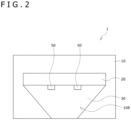
- Fig. 2 illustrates an example of a rear face configuration of this display apparatus 1.
- the display apparatus 1 is configured as a television receiver or the like.
- the display apparatus 1 displays a video image on a video image display surface 10A and outputs a sound from the video image display surface 10A. That is, the display apparatus 1 incorporates a flat panel speaker.
- the display apparatus 1 includes a panel section 10 and a vibration section 20.
- the panel section 10 not only displays a video image but also functions as a diaphragm.
- the vibration section 20 is arranged on a back face of the panel section 10 to vibrate the panel section 10.
- the display apparatus 1 further includes a signal processing section 30 and a support section 40.
- the signal processing section 30 controls the panel section 10 and the vibration section 20.
- the support section 40 supports the panel section 10 via a rotation section 50.
- the vibration section 20 and the signal processing section 30 are arranged on the back face of the panel section 10.
- the panel section 10 has a rear cover 10R for protecting the vibration section 20 and the signal processing section 30 on the back face side of the panel section 10.
- the rear cover 10R includes a plateshaped metallic plate, resin plate, or the like and is connected to the rotation section 50.
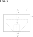
- Fig. 3 illustrates an example of a rear face configuration of the display apparatus 1 with the rear cover 10R removed.
- Fig. 3 illustrates a circuit substrate 30A corresponding to the signal processing section 30.
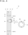
- Fig. 4 illustrates a cross-sectional configuration of major parts along line A-A in Fig. 3 . It should be noted that the detailed configuration of the signal processing section 30 will be described later with reference to Fig. 5 .
- the panel section 10 has a display cell 11 in the shape of a thin plate that displays a video image, an inner plate 12 (opposed plate) arranged to be opposed to the display cell 11 via a gap 15, and a back chassis 13.
- a front face of the display cell 11 (face on the opposite side of the vibration section 20) is the video image display surface 10A.
- the panel section 10 further has a fastening member 14 between the display cell 11 and the inner plate 12.
- the fastening member 14 is arranged along an outer edge of the display cell 11 and has both a function to fasten the display cell 11 and the inner plate 12 together and a function as a spacer to maintain the gap 15.
- the inner plate 12 is a substrate for supporting a vibrator 21.
- the inner plate 12 has an opening for a vibrator at a location where the vibrator 21 is provided.
- the vibration section 20 has a vibrator 21.
- the vibrator 21 is arranged at substantially the center in the horizontal direction when the display cell 11 is viewed from the back face side, and arranged at substantially the center in the vertical direction.
- the back chassis 13 has higher rigidity than the inner plate 12 and plays a role of suppressing deflection and vibration of the inner plate 12. Also, the back chassis 13 has an opening at a position opposed to the opening of the inner plate 12 (e.g., the opening for a vibrator). Of the opening provided in the back chassis 13, the opening provided at the position opposed to the opening for a vibrator has a size allowing the vibrator 21 to be inserted therein.
- the vibrator 21 is an actuator for a speaker that has, for example, a voice coil, a bobbin around which the voice coil is wound, and a magnetic circuit and serves as a vibration source.
- the vibrator 21 When a sound current of an electric signal flows through the voice coil, the vibrator 21 generates a driving force on the voice coil according to a principle of electromagnetic action. This driving force is transmitted to the display cell 11 via a vibration transmitting member 24 to be described later, causes vibration according to a change in sound current, causes air to vibrate, and changes a sound pressure.
- the vibration section 20 has a fastening section 23 and the vibration transmitting member 24 for the vibrator 21.
- the fastening section 23 has an opening 23a and a plurality of threaded holes 23b.
- the opening 23a fastens the vibrator 21 with the vibrator 21 inserted therein.
- the plurality of threaded holes 23b are provided for insertion of screws that are used when the fastening section 23 is fastened to a protruding portion 12A.
- the vibrator 21 is fastened to the inner plate 12 via the fastening section 23.
- the vibration transmitting member 24 is, for example, in contact with the back face of the display cell 11 and the bobbin of the vibrator 21 and fastened to the back face of the display cell 11 and the bobbin of the vibrator 21.
- the vibration transmitting member 24 includes at least a member that has a characteristic of rebounding in a sound wave region (20 Hz or higher).
- the panel section 10 has a damping member 16 between the display cell 11 and the inner plate 12.
- the damping member 16 has an action of hindering vibrations produced in the display cell 11 by the vibrator 21 from interfering with each other.
- the panel section 10 further has an adhesive layer 18 or a sticky layer 19 arranged between the inner plate 12 and the back chassis 13.
- the adhesive layer 18 or the sticky layer 19 is a layer for fastening the inner plate 12 and the back chassis 13 together.
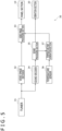
- Fig. 5 illustrates a configuration example of the signal processing section 30.
- the signal processing section 30 includes a tuner 31, a video image decoder 32, a video image processing section 33, a sound decoder 34, a sound processing section 35, a temperature sensor 36, and a temperature map generation section 37.
- the tuner 31 processes a broadcasting signal received by a receiving antenna (not illustrated) and extracts broadcasting streams corresponding to a channel selected by a user.
- the tuner 31 outputs, of the broadcasting streams extracted, a video image stream to the video image decoder 32 and a sound stream to the sound decoder 34.
- the video image decoder 32 performs a decoding process on the video image stream input from the tuner 31 and outputs a video image signal acquired as a result of that process to the video image processing section 33.
- the video image processing section 33 includes a panel driver and drives the panel section 10 (display cell 11 thereof) on the basis of the video image signal input from the video image decoder 32. This allows a video image according to the video image signal to be displayed on the panel section 10.
- the sound decoder 34 performs a decoding process on the sound stream input from the tuner 31 and outputs a sound signal acquired as a result thereof to the sound processing section 35.
- the sound processing section 35 includes a sound device driver and drives the vibration section 20 (vibrator 21 thereof) by amplifying the sound signal input from the sound decoder 34 and outputting the amplified sound signal to the vibration section 20. This allows the panel section 10 (display cell 11 thereof) to vibrate as a diaphragm of the flat panel speaker and a sound (audio) according to the sound signal to be output.
- the sound processing section 35 calculates a power value according to power consumed by the vibration section 20 configured as the flat panel speaker and outputs the power value to the temperature map generation section 37.
- the temperature sensor 36 is provided inside or outside the display apparatus 1.
- the temperature sensor 36 measures an ambient temperature (outside temperature) and outputs a measurement result thereof (measured value of the ambient temperature) to the temperature map generation section 37.
- the temperature map generation section 37 generates a temperature map on the basis of the power value input from the sound processing section 35 and the measured value input from the temperature sensor 36.
- the temperature map generation section 37 generates a gain map corresponding to a temperature map and outputs the gain map to the video image processing section 33.
- the video image processing section 33 controls a level of the video image signal on the basis of the gain map input from the temperature map generation section 37.
- the video image processing section 33 drives the panel section (display cell 11 thereof) on the basis of the video image signal whose level has been adjusted according to the gain map.
- the display apparatus 1 is configured as described above.
- a video image signal from the video image decoder 32 is input to the video image processing section 33 (S11).
- the video image processing section 33 applies, according to the gain map from the temperature map generation section 37 and for each predetermined region of the panel section 10 (display cell 11 thereof), a gain to the video image signal corresponding to the region (S12). This allows the level of the video image signal to be adjusted for each predetermined region.
- the video image processing section 33 drives the panel section 10 (display cell 11 thereof) by outputting, to the panel section 10, a video image signal whose level has been adjusted according to the gain map.
- This image processing applies, in a case where a video image quality is affected because of an increase in luminance of a specific region as a result of transfer of heat generated by the vibration section 20 (vibrator 21 thereof) to the panel section 10 (display cell 11 thereof), a gain to the video image signal for each predetermined region according to the gain map, which suppresses an increase in luminance of a specific region (suppresses an amount of light emitted by the display cell 11) and evens out the luminance of the entire screen region (provides the same luminance for the same video image signal). This makes it possible to suppress effects of heating of the vibration section 20 on the video image quality.
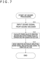
- a sound signal from the sound decoder 34 is input to the sound processing section 35 (S21).
- the sound processing section 35 calculates the power value of the vibration section 20 included in the flat panel speaker and outputs the power value to the temperature map generation section 37 (S22).
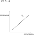
- Fig. 8 illustrates an example of a power value calculation method in the process performed in step S22.
- Fig. 8 illustrates, when a sound signal (output signal) output from the sound processing section 35 to the vibration section 20 is plotted along a horizontal axis and a power value of the vibration section 20 is plotted along a vertical axis, a graph C1 representing a relation between the output signal and the power value.
- the power value of the vibration section 20 is obtained by solving the calculation formula of a predetermined function or referring to a lookup table.
- a power value can be converted into heat and includes a current value according to a current flowing through the vibration section 20 or a voltage value according to a voltage.
- the sound processing section 35 drives the vibration section 20 (vibrator 21 thereof) by amplifying a sound signal and outputting the amplified sound signal to the vibration section 20.
- This sound processing outputs, in a case where the video image quality is affected by an increase in luminance of a specific region as a result of transfer of heat generated by the vibration section 20 (vibrator 21 thereof) to the panel section 10 (display cell 11 thereof), a power value of the vibration section 20 included in the flat panel speaker to the temperature map generation section 37, which generates a gain map according to a temperature map.
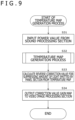
- a power value from the sound processing section 35 is input to the temperature map generation section 37 (S31).
- the temperature map generation section 37 performs the temperature map generation process (S32). This temperature map generation process generates a temperature map on the basis of the input power value and the ambient temperature acquired by the temperature sensor 36.
- the temperature map generation process will be described in detail later with reference to Figs. 11 to 14 .
- step S32 When a temperature map to be output is generated by the process in step S32, the process proceeds to step S33.
- the temperature map generation section 37 calculates a reverse correction value for suppressing an amount of light emitted by the panel section 10 (display cell 11 thereof) from the temperature map to be output (S33).
- the temperature map generation section 37 outputs, to the video image processing section 33, a gain map of the correction value acquired from the calculated reverse correction value (S34).
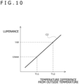
- Fig. 10 illustrates an example of a reverse correction value calculation method in the process performed in step S33.
- Fig. 10 illustrates, when a temperature difference from an outside temperature is plotted along the horizontal axis and luminance (brightness of the screen) of the display cell 11 of the panel section 10 is plotted along the vertical axis, a graph C2 representing a relation between the temperature difference from the outside temperature and the luminance.
- a temperature difference T11 and a temperature difference T12 into variables of the function as values indicating the temperature differences from the outside temperature.
- the temperature difference T11 is a temperature difference in a region corresponding to a portion of the panel section 10 where the vibration section 20 (vibrator 21 thereof) is not provided.
- the temperature difference T12 is a temperature difference in a region corresponding to a portion of the panel section 10 where the vibration section 20 (vibrator 21 thereof) is provided.
- luminance Lbase is calculated by substituting the temperature difference T11 into a variable of the function
- luminance Lsp is calculated by substituting the temperature difference T12 into a variable of the function.
- a gain of a correction value is obtained as a reverse correction value for suppressing an amount of light emitted by the panel section 10 (display cell 11 thereof) by substituting the luminance Lbase and the luminance Lsp into the following formula (1).
- Gain Lbase / Lsp
- the luminance of the display cell 11 increases according to the increase in temperature. Accordingly, if there is a temperature difference between the region corresponding to the portion of the display cell 11 where the vibrator 21 is provided and the region corresponding to the portion of the display cell 11 where the vibrator 21 is not provided, there will be a difference in luminance between these regions.
- a gain is obtained by using the above formula (1) to match the luminance of the region corresponding to the portion where the vibrator 21 is provided with the luminance of the region corresponding to the portion where the vibrator 21 is not provided. Then, it is possible, by using this gain as a correction value and controlling the level of the video image signal, to suppress the amount of light emitted by the display cell 11 in the region corresponding to the portion where the vibrator 21 is provided (region where the luminance increases) and to even out the luminance.
- the luminance or gain may also be obtained here by retaining, in advance, the luminance or gain corresponding to the temperature difference from the outside temperature as a lookup table and referring to the lookup table.
- a reverse correction value according to the temperature difference from the outside temperature is calculated for each predetermined region of the temperature map to be output (divided block obtained by dividing the screen of the panel section 10 by a predetermined division unit), and a gain map including a correction value (gain) for each predetermined region is generated.
- This temperature map generation process generates, in a case where the video image quality is affected by an increase in luminance of a specific region as a result of transfer of heat generated by the vibration section 20 (vibrator 21 thereof) to the panel section 10 (display cell 11 thereof), a temperature map based on a power value from the sound processing section 35 and outputs a gain map corresponding to the temperature map to the video image processing section 33, which causes the video image processing section 33 to apply a gain to the video image signal for each predetermined region according to the gain map and suppresses the increase in luminance of a specific region.
- the temperature map generation section 37 acquires a measured value of the ambient temperature (outside temperature) from the temperature sensor 36 (S41).
- step S41 When the measured value of the ambient temperature is acquired by the process in step S41, the process proceeds to step S42.
- the temperature map generation section 37 converts the power value input from the sound processing section 35 into a temperature increase and adds the converted value to the temperature map (S42).
- Fig. 12 illustrates an example of a method of converting a power value into a temperature increase in the process in step S42.
- Fig. 12 illustrates, when a power value of the vibration section 20 is plotted along the horizontal axis and a temperature increase is plotted along the vertical axis, a graph C3 representing a relation between the power value and the temperature increase.
- Fig. 12 in a case where the relation between the power value and the temperature increase is represented by the graph C3 of a predetermined function, the power value is converted into the temperature increase by substituting the power value into a variable of the function.
- the temperature increase according to the power value is obtained for each predetermined region (divided block) of the temperature map.
- the power value may also be converted into the temperature increase here by retaining, in advance, the temperature increase corresponding to the power value as a lookup table and referring to the lookup table. At this time, a plurality of lookup tables according to the ambient temperature or the like may be prepared. Alternatively, a coefficient may be applied to the lookup table.
- the temperature map generation section 37 treats the temperature map to which the temperature increase according to the power value has been added as a map to be output to the video image processing section 33 (S43).
- the temperature map generation section 37 planarly diffuses the temperature (heat) from the temperature difference between a divided block of interest on which attention is focused and surrounding divided blocks, in the temperature map (S44), and calculates an amount of radiated heat from the temperature difference from the outside temperature and subtracts the amount of radiated heat from the temperature map (S45).
- Fig. 13 illustrates an example of planar diffusion of a temperature map in the process in step S44.
- the divided block 111 at the center (dot pattern region in Fig. 13 ) is treated as the divided block 111 of interest, and the temperature (heat) is planarly diffused to the surrounding eight divided blocks 111 according to the temperature difference as illustrated by arrows that extend in eight directions therefrom.
- Fig. 14 illustrates an example of a calculation method of an amount of radiated heat in the process in step S45.
- Fig. 14 illustrates, when a temperature difference from the outside temperature is plotted along the horizontal axis and an amount of radiated heat is plotted along the vertical axis, a graph C4 representing a relation between the temperature difference from the outside temperature and the amount of radiated heat.
- Fig. 14 in a case where the relation between the temperature difference from the outside temperature and the amount of radiated heat is represented by the graph C4 of a predetermined function, the amount of radiated heat according to the temperature difference from the outside temperature is calculated by substituting the temperature difference from the outside temperature into a variable of the function.
- the amount of radiated heat according to the temperature difference from the outside temperature may also be obtained here by retaining, in advance, the amount of radiated heat corresponding to the temperature difference from the outside temperature as the lookup table and referring to the lookup table.
- the process returns to step S42.
- the temperature map generation section 37 adds the temperature increase according to the power value to the temperature map (S42) and treats the temperature map as a temperature map to be output (S43).
- the temperature increase according to the power value of the vibration section 20 is added to the temperature map, the temperature map is planarly diffused, and the amount of radiated heat is subtracted with passage of time. Accordingly, the temperature map in which not only the temperature increase caused by heating of the vibration section 20 (vibrator 21 thereof) but also effects such as the amount of radiated heat according to the outside temperature are taken into account, every unit time, is generated and is treated as a temperature map to be output.
- step S43 ends, the process returns to step S32 in Fig. 9 , and the subsequent processes are performed.
- thermo map generation process illustrated in Fig. 11 is merely an example, and a temperature map may be generated by using another generation method.
- the temperature map generation section 37 may calculate an integral value (integral power) obtained by integrating the power value of the vibration section 20 over a unit time and generate a temperature map on the basis of this integral value.
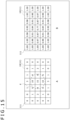
- the relation between the temperature map to be output that is generated by the process in step S32 in Fig. 9 and the gain map output by the process in step S34 in Fig. 9 is, for example, as illustrated in Fig. 15 .
- the gain map in B of Fig. 15 is acquired from the temperature map in A of Fig. 15 by applying the reverse correction value calculation method illustrated in Fig. 10 to the process in step S33 in Fig. 9 .
- the position of the vibration section 20 (vibrator 21) relative to the panel section 10 (display cell 11) is indicated by a position P according to a dashed line circle in A of Fig. 15 .
- a numeric value indicating a gain is given in the gain map for each divided block 111 in B of Fig. 15 .
- the gain of each divided block 111 in the gain map of B of Fig. 15 is obtained by applying the reverse correction value calculation method illustrated in Fig. 10 to the temperature map in A of Fig. 15 .
- the video image processing section 33 applies a gain to the video image signal for each divided block 111 according to the gain map, which decreases the video image signal level of the region at high temperature, suppresses the increase in luminance of the region, and evens out the luminance of the entire screen region (provides the same luminance for the same video image signal).
- the level of the video image signal is decreased in the former divided block 111. Accordingly, if the same video image signal is input, the luminance is the same. This makes it possible to suppress effects of heating of the vibration section 20 on the video image quality and improve the video image quality.
- a unit of division can be set as desired such as dividing the screen into even smaller portions and calculating a gain for each unit of division.
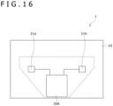
- Fig. 16 illustrates a configuration example of the rear face of the display apparatus 1 in a case where the two vibrators 21 are provided.
- the vibration section 20 has two vibrators 21a and 21b.
- the vibrators 21a and 21b have a similar configuration to the vibrator 21 described above and have a configuration common to each other. That is, the vibrators 21a and 21b are speaker actuators each of which has, for example, a voice coil, a bobbin around which the voice coil is wound, and a magnetic circuit, to serve as a vibration source.
- the vibrator 21a When the display cell 11 is seen from the back face side, the vibrator 21a is horizontally arranged closer to the left, and the vibrator 21b is arranged closer to the right. Also, both the vibrators 21a and 21b are vertically arranged approximately at the center.
- the temperature map generation process ( Fig. 9 ) is performed similarly to the case where the single vibrator 21 is provided. However, it is assumed that the temperature maps have different distributions.
- the relation between the temperature map and the gain map in the case where the two vibrators 21a and 21b are provided is, for example, as illustrated in Fig. 17 .
- the gain map in B of Fig. 17 is acquired from the temperature map in A of Fig. 17 by applying the reverse correction value calculation method illustrated in Fig. 10 to the process in step S33 in Fig. 9 . It should be noted, however, that, in A of Fig. 17 , the positions of the vibrators 21b and 21a relative to the panel section 10 (display cell 11) are indicated by positions P1 and P2 according to dashed line circles in A of Fig. 17 .
- the temperature map indicates a temperature increase in each divided block 111 by the numeric value given in each divided block 111.
- a numeric value indicating a gain is given in the gain map for each divided block 111 in B of Fig. 17 .
- the gain of each divided block 111 in the gain map of B of Fig. 17 is obtained by applying the reverse correction value calculation method illustrated in Fig. 10 to the temperature map in A of Fig. 17 .
- the video image processing section 33 applies a gain to the video image signal for each divided block 111 according to the gain map, which decreases the video image signal level of the region with high temperature, suppresses the increase in luminance of the region, and evens out the luminance of the entire screen region. This makes it possible to suppress effects of heating of the vibration section 20 on the video image quality and improve the video image quality.
- the number of vibrators 21 is not limited to one or two, and the plurality of vibrators 21, i.e., three or more vibrators 21, can be used. Even in the case where the three or more vibrators 21 are provided, it is possible to generate a temperature map according to the three or more vibrators 21 by performing the temperature map generation process ( Fig. 9 ).
- the vibrator 21 which is a speaker actuator serving as a vibration source includes a voice coil, and if a sound current of an electric signal flows through the voice coil, the vibrator 21 generates a driving force on the voice coil in accordance with the principle of electromagnetic action.
- the vibrator 21 is not limited to a voice coil, and another actuator such as a voltage actuator may also be used.
- the display apparatus 1 is not limited to this case and may be a personal computer, a tablet terminal, a smartphone, a mobile phone, a game console, a display unit, or other pieces of electronic equipment. Further, the display apparatus 1 may be a digital signage, a medical monitor, a business monitor for broadcasting station (monitor for professional use), a vehicle-mounted display, or the like.
- an OLED (Organic Light Emitting Diode) display section which is a display panel having pixels, each including a selfluminous element and arranged two-dimensionally
- a liquid crystal display section which is a display panel having pixels, each including a liquid crystal element and a TFT (Thin Film Transistor) element, arranged two-dimensionally, or the like can be used as the panel section 10.
- a communication circuit (communication module) that supports a predetermined communication scheme, HDMI (registered trademark) (High Definition Multimedia Interface), an interface that complies with a predetermined standard such as a USB (Universal Serial Bus), or the like may be provided in the display apparatus 1.
- HDMI registered trademark
- USB Universal Serial Bus
- the display apparatus 1 reproduces not only broadcast content received via the tuner 31 but also communication content streamed by a video delivery service (e.g., OTT (Over The Top) service) via a communication network such as the Internet and recorded content recorded by a recording unit (recording/reproduction unit).
- OTT Over The Top
- the signal processing section 30 in Fig. 5 may be configured as a standalone apparatus as a signal processing apparatus.
- the signal processing apparatus may not include some of the components such as the tuner 31, the video image decoder 32, the sound decoder 34, or the temperature sensor 36.
- the signal processing apparatus may include other components.
- the temperature sensor 36 may be not only provided inside or outside the display apparatus 1 but also incorporated in the panel section 10 (display cell 11).
Landscapes
- Engineering & Computer Science (AREA)
- Physics & Mathematics (AREA)
- Signal Processing (AREA)
- Computer Hardware Design (AREA)
- General Physics & Mathematics (AREA)
- Theoretical Computer Science (AREA)
- Multimedia (AREA)
- Acoustics & Sound (AREA)
- Control Of Indicators Other Than Cathode Ray Tubes (AREA)
- Transforming Electric Information Into Light Information (AREA)
- Television Receiver Circuits (AREA)
Claims (11)
- Anzeigeeinrichtung (1), umfassend:einen Signalverarbeitungsabschnitt (30), der geeignet ist, um ein Videobildsignal und ein Tonsignal zu verarbeiten ;einen Bedienfeldabschnitt (10) in einer Plattenform, der geeignet ist, um ein Videobild, das dem Videobildsignal entspricht, anzuzeigen ; undeinen Vibrationsabschnitt (20), der auf einer Rückflächenseite des Bedienfeldabschnitts angeordnet ist, der geeignet ist, um den Bedienfeldabschnitt gemäß dem Tonsignal in Vibration zu versetzen, wobeider Signalverarbeitungsabschnitt geeignet ist, um einen Korrekturwert zum Unterdrücken einer Zunahme der Leuchtdichte zu berechnen, die durch den Bedienfeldabschnitt abgegeben wird, die durch eine Übertragung von Wärme, die durch den Vibrationsabschnitt erzeugt wird, verursacht wird, basierend auf einem Leistungswert eines Tonsignals, der an den Vibrationsabschnitt ausgegeben wird, und um einen Pegel des Videobildsignals auf einer Basis des berechneten Korrekturwerts zu steuern.
- Anzeigeeinrichtung nach Anspruch 1, wobeider Signalverarbeitungsabschnitt geeignet ist, um eine Temperaturkarte auf einer Basis des Leistungswerts und einer Umgebungstemperatur einer umgebenden Region zu erzeugen,Erzeugen einer Verstärkungskarte des Korrekturwerts auf einer Basis der erzeugten Temperaturkarte und um einen Pegel des Videobildsignals auf einer Basis der erzeugten Verstärkungskarte zu steuern.
- Anzeigeeinrichtung nach Anspruch 2, wobei
der Signalverarbeitungsabschnitt geeignet ist, um einen umgekehrten Korrekturwert zum Unterdrücken einer Menge an Licht, die durch den Bedienfeldabschnitt abgegeben wird, auf der Basis der erzeugten Temperaturkarte zu berechnen und um die Verstärkungskarte auf einer Basis des berechneten umgekehrten Korrekturwerts zu erzeugen. - Anzeigeeinrichtung nach einem der Ansprüche 2 oder 3, wobei
im Laufe der Zeit der Temperaturkarte eine Temperaturerhöhung gemäß dem Leistungswert hinzugefügt und eine Menge an abgestrahlter Wärme gemäß der Umgebungstemperatur davon abgezogen wird. - Anzeigeeinrichtung nach einem der Ansprüche 2 bis 4, wobei
der Signalverarbeitungsabschnitt geeignet ist, um einen Pegel des Videobildsignals für jede zuvor bestimmte Region des Bedienfeldabschnitts auf der Basis der Verstärkungskarte zu steuern. - Anzeigeeinrichtung nach Anspruch 3, wobei
der umgekehrte Korrekturwert ein Wert gemäß einer Verstärkung zum Anpassen der Leuchtdichte einer Region ist, die einem Teil des Plattenabschnitts entspricht, in dem der Vibrationsabschnitt mit einer Leuchtdichte einer Region bereitgestellt ist, die einem Teil des Plattenabschnitts entspricht, in dem der Vibrationsabschnitt nicht bereitgestellt ist. - Anzeigeeinrichtung nach Anspruch 1, wobei
der Signalverarbeitungsabschnitt geeignet ist, um eine Temperaturkarte auf einer Basis eines Integralwerts zu erzeugen, der durch Integrieren des Leistungswerts über eine Zeiteinheit erhalten wird, eine Verstärkungskarte des Korrekturwerts auf einer Basis der erzeugten Temperaturkarte zu erzeugen und den Pegel des Videobildsignals auf einer Basis der erzeugten Verstärkungskarte zu steuern. - Anzeigeeinrichtung nach Anspruch 7, wobei
der Signalverarbeitungsabschnitt geeignet ist, um den Pegel des Videobildsignals für jede zuvor bestimmte Region des Bedienfeldabschnitts auf der Basis der Verstärkungskarte zu steuern. - Anzeigeeinrichtung nach einem der Ansprüche 1 bis 8, wobei
der Vibrationsabschnitt einen oder eine Vielzahl von Vibratoren einschließt. - Anzeigeeinrichtung nach einem der Ansprüche 1 bis 9, wobei
der Signalverarbeitungsabschnitt geeignet ist, um ein Videobildsignal und ein Tonsignal mit Inhalt zu verarbeiten. - Anzeigeeinrichtung nach einem der Ansprüche 1 bis 10, die als ein Fernsehempfänger konfiguriert ist.
Applications Claiming Priority (2)
| Application Number | Priority Date | Filing Date | Title |
|---|---|---|---|
| JP2019140676 | 2019-07-31 | ||
| PCT/JP2020/027788 WO2021020157A1 (ja) | 2019-07-31 | 2020-07-17 | 表示装置 |
Publications (3)
| Publication Number | Publication Date |
|---|---|
| EP4007294A1 EP4007294A1 (de) | 2022-06-01 |
| EP4007294A4 EP4007294A4 (de) | 2022-09-07 |
| EP4007294B1 true EP4007294B1 (de) | 2025-06-11 |
Family
ID=74229084
Family Applications (1)
| Application Number | Title | Priority Date | Filing Date |
|---|---|---|---|
| EP20846301.8A Active EP4007294B1 (de) | 2019-07-31 | 2020-07-17 | Anzeigevorrichtung |
Country Status (6)
| Country | Link |
|---|---|
| US (1) | US11902698B2 (de) |
| EP (1) | EP4007294B1 (de) |
| JP (1) | JP7517338B2 (de) |
| KR (1) | KR102817492B1 (de) |
| CN (1) | CN114145010B (de) |
| WO (1) | WO2021020157A1 (de) |
Family Cites Families (21)
| Publication number | Priority date | Publication date | Assignee | Title |
|---|---|---|---|---|
| JP2006011086A (ja) * | 2004-06-25 | 2006-01-12 | Funai Electric Co Ltd | 液晶テレビジョン受像機および液晶表示装置 |
| JP2007034120A (ja) * | 2005-07-29 | 2007-02-08 | Sharp Corp | 直下式バックライト装置および直下式バックライト装置を用いた液晶表示装置 |
| JP2008181109A (ja) * | 2006-12-27 | 2008-08-07 | Semiconductor Energy Lab Co Ltd | 液晶表示装置及びそれを用いた電子機器 |
| US7708419B2 (en) | 2007-03-02 | 2010-05-04 | Himax Technologies Limited | Ambient light system and method thereof |
| JP5147311B2 (ja) * | 2007-06-28 | 2013-02-20 | 三星電子株式会社 | 映像信号処理装置、映像信号処理方法、プログラム、および表示装置 |
| JP2009276744A (ja) | 2008-02-13 | 2009-11-26 | Toshiba Mobile Display Co Ltd | El表示装置 |
| JP2009302924A (ja) * | 2008-06-13 | 2009-12-24 | Azden Corp | 平面スピーカ用トランスデューサ、平面スピーカ、スクリーン及び広告バナー |
| JP4968219B2 (ja) * | 2008-09-18 | 2012-07-04 | 株式会社Jvcケンウッド | 液晶表示装置及びこれに用いる映像表示方法 |
| JP2010139782A (ja) * | 2008-12-11 | 2010-06-24 | Sony Corp | 表示装置、表示装置の駆動方法およびプログラム |
| US8774419B2 (en) | 2011-09-28 | 2014-07-08 | Texas Instruments Incorporated | Thermal control of voice coils in loudspeakers |
| JP5622952B2 (ja) * | 2013-03-19 | 2014-11-12 | シャープ株式会社 | 液晶表示装置およびその設定方法 |
| US9520094B2 (en) * | 2013-10-22 | 2016-12-13 | Japan Display Inc. | Display device, electronic apparatus, and method for driving display device |
| CN105323511A (zh) * | 2014-07-03 | 2016-02-10 | 日照海帝电器有限公司 | 一种智能电视及其温度控制保护系统和方法 |
| US9807528B1 (en) | 2015-09-21 | 2017-10-31 | Apple Inc. | Electronic devices and method for thermal monitoring of an electro-mechanical actuator |
| JP6628575B2 (ja) * | 2015-11-24 | 2020-01-08 | アルパイン株式会社 | 表示装置および輝度ムラ制御方法 |
| US11659309B2 (en) * | 2016-02-27 | 2023-05-23 | Sony Group Corporation | Display apparatus |
| KR101704517B1 (ko) * | 2016-03-28 | 2017-02-09 | 엘지디스플레이 주식회사 | 패널 진동형 음향 발생 표시 장치 |
| KR102259805B1 (ko) * | 2016-11-30 | 2021-06-02 | 엘지디스플레이 주식회사 | 표시 장치 |
| WO2018123310A1 (ja) | 2016-12-27 | 2018-07-05 | ソニー株式会社 | フラットパネルスピーカおよび表示装置 |
| EP3518223A4 (de) * | 2017-09-12 | 2020-01-08 | Sony Corporation | Anzeigevorrichtung und signalverarbeitungsverfahren |
| CN107452345B (zh) * | 2017-09-29 | 2020-01-10 | 京东方科技集团股份有限公司 | 一种显示器件亮度补偿方法、装置及显示装置 |
-
2020
- 2020-07-17 EP EP20846301.8A patent/EP4007294B1/de active Active
- 2020-07-17 JP JP2021536938A patent/JP7517338B2/ja active Active
- 2020-07-17 WO PCT/JP2020/027788 patent/WO2021020157A1/ja not_active Ceased
- 2020-07-17 CN CN202080053290.XA patent/CN114145010B/zh active Active
- 2020-07-17 KR KR1020227001073A patent/KR102817492B1/ko active Active
- 2020-07-17 US US17/628,443 patent/US11902698B2/en active Active
Also Published As
| Publication number | Publication date |
|---|---|
| US11902698B2 (en) | 2024-02-13 |
| WO2021020157A1 (ja) | 2021-02-04 |
| JPWO2021020157A1 (de) | 2021-02-04 |
| KR102817492B1 (ko) | 2025-06-10 |
| EP4007294A1 (de) | 2022-06-01 |
| JP7517338B2 (ja) | 2024-07-17 |
| CN114145010A (zh) | 2022-03-04 |
| CN114145010B (zh) | 2024-09-17 |
| KR20220043107A (ko) | 2022-04-05 |
| EP4007294A4 (de) | 2022-09-07 |
| US20220272299A1 (en) | 2022-08-25 |
Similar Documents
| Publication | Publication Date | Title |
|---|---|---|
| US10681441B2 (en) | Display apparatus | |
| US9571888B2 (en) | Selection graphics overlay of matrix code | |
| US11625065B2 (en) | Display apparatus | |
| US10993036B2 (en) | Sound generating device, display apparatus including the same, and automotive apparatus including the sound generating device | |
| CN111970614B (zh) | 显示装置以及用该显示装置再现声音的方法 | |
| KR20160049230A (ko) | 디지털 디바이스 및 그 제어 방법 | |
| CN104036696A (zh) | 显示设备及其控制方法 | |
| US11902698B2 (en) | Display apparatus | |
| DE60227456D1 (de) | Fernsehsystem mit elektronischem Programmführer | |
| US12131692B2 (en) | Signal processing apparatus, signal processing method, and display apparatus | |
| WO2018003643A1 (ja) | 映像表示装置、テレビジョン受像機、送信装置、制御プログラム及び記録媒体 | |
| US11800285B2 (en) | Display device | |
| KR20160059277A (ko) | 디지털 디바이스 및 그 제어 방법 | |
| US20250384851A1 (en) | Display device and operating method thereof | |
| CN116830597A (zh) | 再现系统、显示装置和再现装置 | |
| KR100702237B1 (ko) | 영상처리장치 및 그 제어방법 | |
| JP2021164090A (ja) | 映像処理装置、テレビ受信機、及びプログラム | |
| JP2011244375A (ja) | デジタル字幕放送およびデジタル字幕放送用モニタの表示方法 | |
| KR20100028212A (ko) | 디스플레이장치에서의 음성신호 출력 장치 및 방법 | |
| KR20140110688A (ko) | 디스플레이장치 및 그 제어방법 | |
| JP2013042308A (ja) | 画像処理装置、画像処理方法、および表示システム | |
| JP2013059089A (ja) | 画像処理装置、画像処理方法、および表示システム | |
| TW201006261A (en) | System and method for adjusting sound volume according to preset time | |
| JP2007072247A (ja) | 表示制御装置および方法、並びにプログラム |
Legal Events
| Date | Code | Title | Description |
|---|---|---|---|
| STAA | Information on the status of an ep patent application or granted ep patent |
Free format text: STATUS: THE INTERNATIONAL PUBLICATION HAS BEEN MADE |
|
| PUAI | Public reference made under article 153(3) epc to a published international application that has entered the european phase |
Free format text: ORIGINAL CODE: 0009012 |
|
| STAA | Information on the status of an ep patent application or granted ep patent |
Free format text: STATUS: REQUEST FOR EXAMINATION WAS MADE |
|
| 17P | Request for examination filed |
Effective date: 20220228 |
|
| AK | Designated contracting states |
Kind code of ref document: A1 Designated state(s): AL AT BE BG CH CY CZ DE DK EE ES FI FR GB GR HR HU IE IS IT LI LT LU LV MC MK MT NL NO PL PT RO RS SE SI SK SM TR |
|
| REG | Reference to a national code |
Ref country code: DE Ref legal event code: R079 Free format text: PREVIOUS MAIN CLASS: H04R0001020000 Ipc: G09G0003200000 Ref country code: DE Ref legal event code: R079 Ref document number: 602020052723 Country of ref document: DE Free format text: PREVIOUS MAIN CLASS: H04R0001020000 Ipc: G09G0003200000 |
|
| A4 | Supplementary search report drawn up and despatched |
Effective date: 20220805 |
|
| RIC1 | Information provided on ipc code assigned before grant |
Ipc: G09G 5/10 20060101ALI20220801BHEP Ipc: H04N 5/60 20060101ALI20220801BHEP Ipc: H04N 5/57 20060101ALI20220801BHEP Ipc: H04R 7/04 20060101ALI20220801BHEP Ipc: H04R 1/02 20060101ALI20220801BHEP Ipc: G09G 3/20 20060101AFI20220801BHEP |
|
| DAV | Request for validation of the european patent (deleted) | ||
| DAX | Request for extension of the european patent (deleted) | ||
| GRAP | Despatch of communication of intention to grant a patent |
Free format text: ORIGINAL CODE: EPIDOSNIGR1 |
|
| STAA | Information on the status of an ep patent application or granted ep patent |
Free format text: STATUS: GRANT OF PATENT IS INTENDED |
|
| INTG | Intention to grant announced |
Effective date: 20250116 |
|
| P01 | Opt-out of the competence of the unified patent court (upc) registered |
Free format text: CASE NUMBER: APP_7188/2025 Effective date: 20250212 |
|
| GRAS | Grant fee paid |
Free format text: ORIGINAL CODE: EPIDOSNIGR3 |
|
| GRAA | (expected) grant |
Free format text: ORIGINAL CODE: 0009210 |
|
| STAA | Information on the status of an ep patent application or granted ep patent |
Free format text: STATUS: THE PATENT HAS BEEN GRANTED |
|
| AK | Designated contracting states |
Kind code of ref document: B1 Designated state(s): AL AT BE BG CH CY CZ DE DK EE ES FI FR GB GR HR HU IE IS IT LI LT LU LV MC MK MT NL NO PL PT RO RS SE SI SK SM TR |
|
| REG | Reference to a national code |
Ref country code: GB Ref legal event code: FG4D |
|
| REG | Reference to a national code |
Ref country code: CH Ref legal event code: EP |
|
| REG | Reference to a national code |
Ref country code: IE Ref legal event code: FG4D |
|
| REG | Reference to a national code |
Ref country code: DE Ref legal event code: R096 Ref document number: 602020052723 Country of ref document: DE |
|
| REG | Reference to a national code |
Ref country code: NL Ref legal event code: FP |
|
| PGFP | Annual fee paid to national office [announced via postgrant information from national office to epo] |
Ref country code: NL Payment date: 20250723 Year of fee payment: 6 |
|
| PG25 | Lapsed in a contracting state [announced via postgrant information from national office to epo] |
Ref country code: ES Free format text: LAPSE BECAUSE OF FAILURE TO SUBMIT A TRANSLATION OF THE DESCRIPTION OR TO PAY THE FEE WITHIN THE PRESCRIBED TIME-LIMIT Effective date: 20250611 Ref country code: FI Free format text: LAPSE BECAUSE OF FAILURE TO SUBMIT A TRANSLATION OF THE DESCRIPTION OR TO PAY THE FEE WITHIN THE PRESCRIBED TIME-LIMIT Effective date: 20250611 |
|
| PGFP | Annual fee paid to national office [announced via postgrant information from national office to epo] |
Ref country code: DE Payment date: 20250724 Year of fee payment: 6 |
|
| REG | Reference to a national code |
Ref country code: LT Ref legal event code: MG9D |
|
| PG25 | Lapsed in a contracting state [announced via postgrant information from national office to epo] |
Ref country code: NO Free format text: LAPSE BECAUSE OF FAILURE TO SUBMIT A TRANSLATION OF THE DESCRIPTION OR TO PAY THE FEE WITHIN THE PRESCRIBED TIME-LIMIT Effective date: 20250911 Ref country code: GR Free format text: LAPSE BECAUSE OF FAILURE TO SUBMIT A TRANSLATION OF THE DESCRIPTION OR TO PAY THE FEE WITHIN THE PRESCRIBED TIME-LIMIT Effective date: 20250912 |
|
| PG25 | Lapsed in a contracting state [announced via postgrant information from national office to epo] |
Ref country code: BG Free format text: LAPSE BECAUSE OF FAILURE TO SUBMIT A TRANSLATION OF THE DESCRIPTION OR TO PAY THE FEE WITHIN THE PRESCRIBED TIME-LIMIT Effective date: 20250611 |
|
| PGFP | Annual fee paid to national office [announced via postgrant information from national office to epo] |
Ref country code: GB Payment date: 20250725 Year of fee payment: 6 |
|
| PG25 | Lapsed in a contracting state [announced via postgrant information from national office to epo] |
Ref country code: HR Free format text: LAPSE BECAUSE OF FAILURE TO SUBMIT A TRANSLATION OF THE DESCRIPTION OR TO PAY THE FEE WITHIN THE PRESCRIBED TIME-LIMIT Effective date: 20250611 |
|
| PGFP | Annual fee paid to national office [announced via postgrant information from national office to epo] |
Ref country code: FR Payment date: 20250723 Year of fee payment: 6 |
|
| PG25 | Lapsed in a contracting state [announced via postgrant information from national office to epo] |
Ref country code: RS Free format text: LAPSE BECAUSE OF FAILURE TO SUBMIT A TRANSLATION OF THE DESCRIPTION OR TO PAY THE FEE WITHIN THE PRESCRIBED TIME-LIMIT Effective date: 20250911 |
|
| PG25 | Lapsed in a contracting state [announced via postgrant information from national office to epo] |
Ref country code: LV Free format text: LAPSE BECAUSE OF FAILURE TO SUBMIT A TRANSLATION OF THE DESCRIPTION OR TO PAY THE FEE WITHIN THE PRESCRIBED TIME-LIMIT Effective date: 20250611 |
|
| PG25 | Lapsed in a contracting state [announced via postgrant information from national office to epo] |
Ref country code: PT Free format text: LAPSE BECAUSE OF FAILURE TO SUBMIT A TRANSLATION OF THE DESCRIPTION OR TO PAY THE FEE WITHIN THE PRESCRIBED TIME-LIMIT Effective date: 20251013 |
|
| REG | Reference to a national code |
Ref country code: AT Ref legal event code: MK05 Ref document number: 1802913 Country of ref document: AT Kind code of ref document: T Effective date: 20250611 |
|
| PG25 | Lapsed in a contracting state [announced via postgrant information from national office to epo] |
Ref country code: IS Free format text: LAPSE BECAUSE OF FAILURE TO SUBMIT A TRANSLATION OF THE DESCRIPTION OR TO PAY THE FEE WITHIN THE PRESCRIBED TIME-LIMIT Effective date: 20251011 |
|
| PG25 | Lapsed in a contracting state [announced via postgrant information from national office to epo] |
Ref country code: AT Free format text: LAPSE BECAUSE OF FAILURE TO SUBMIT A TRANSLATION OF THE DESCRIPTION OR TO PAY THE FEE WITHIN THE PRESCRIBED TIME-LIMIT Effective date: 20250611 Ref country code: SM Free format text: LAPSE BECAUSE OF FAILURE TO SUBMIT A TRANSLATION OF THE DESCRIPTION OR TO PAY THE FEE WITHIN THE PRESCRIBED TIME-LIMIT Effective date: 20250611 |
|
| PG25 | Lapsed in a contracting state [announced via postgrant information from national office to epo] |
Ref country code: CZ Free format text: LAPSE BECAUSE OF FAILURE TO SUBMIT A TRANSLATION OF THE DESCRIPTION OR TO PAY THE FEE WITHIN THE PRESCRIBED TIME-LIMIT Effective date: 20250611 |
|
| PG25 | Lapsed in a contracting state [announced via postgrant information from national office to epo] |
Ref country code: PL Free format text: LAPSE BECAUSE OF FAILURE TO SUBMIT A TRANSLATION OF THE DESCRIPTION OR TO PAY THE FEE WITHIN THE PRESCRIBED TIME-LIMIT Effective date: 20250611 |
|
| PG25 | Lapsed in a contracting state [announced via postgrant information from national office to epo] |
Ref country code: EE Free format text: LAPSE BECAUSE OF FAILURE TO SUBMIT A TRANSLATION OF THE DESCRIPTION OR TO PAY THE FEE WITHIN THE PRESCRIBED TIME-LIMIT Effective date: 20250611 |
|
| PG25 | Lapsed in a contracting state [announced via postgrant information from national office to epo] |
Ref country code: SK Free format text: LAPSE BECAUSE OF FAILURE TO SUBMIT A TRANSLATION OF THE DESCRIPTION OR TO PAY THE FEE WITHIN THE PRESCRIBED TIME-LIMIT Effective date: 20250611 Ref country code: RO Free format text: LAPSE BECAUSE OF FAILURE TO SUBMIT A TRANSLATION OF THE DESCRIPTION OR TO PAY THE FEE WITHIN THE PRESCRIBED TIME-LIMIT Effective date: 20250611 |
|
| REG | Reference to a national code |
Ref country code: CH Ref legal event code: H13 Free format text: ST27 STATUS EVENT CODE: U-0-0-H10-H13 (AS PROVIDED BY THE NATIONAL OFFICE) Effective date: 20260224 |
|
| REG | Reference to a national code |
Ref country code: DE Ref legal event code: R097 Ref document number: 602020052723 Country of ref document: DE |
|
| PG25 | Lapsed in a contracting state [announced via postgrant information from national office to epo] |
Ref country code: LU Free format text: LAPSE BECAUSE OF NON-PAYMENT OF DUE FEES Effective date: 20250717 |
|
| REG | Reference to a national code |
Ref country code: BE Ref legal event code: MM Effective date: 20250731 |
|
| PG25 | Lapsed in a contracting state [announced via postgrant information from national office to epo] |
Ref country code: MC Free format text: LAPSE BECAUSE OF FAILURE TO SUBMIT A TRANSLATION OF THE DESCRIPTION OR TO PAY THE FEE WITHIN THE PRESCRIBED TIME-LIMIT Effective date: 20250611 |
|
| PG25 | Lapsed in a contracting state [announced via postgrant information from national office to epo] |
Ref country code: DK Free format text: LAPSE BECAUSE OF FAILURE TO SUBMIT A TRANSLATION OF THE DESCRIPTION OR TO PAY THE FEE WITHIN THE PRESCRIBED TIME-LIMIT Effective date: 20250611 |
|
| PG25 | Lapsed in a contracting state [announced via postgrant information from national office to epo] |
Ref country code: IT Free format text: LAPSE BECAUSE OF FAILURE TO SUBMIT A TRANSLATION OF THE DESCRIPTION OR TO PAY THE FEE WITHIN THE PRESCRIBED TIME-LIMIT Effective date: 20250611 Ref country code: BE Free format text: LAPSE BECAUSE OF NON-PAYMENT OF DUE FEES Effective date: 20250731 |
|
| PLBE | No opposition filed within time limit |
Free format text: ORIGINAL CODE: 0009261 |
|
| STAA | Information on the status of an ep patent application or granted ep patent |
Free format text: STATUS: NO OPPOSITION FILED WITHIN TIME LIMIT |
|
| PG25 | Lapsed in a contracting state [announced via postgrant information from national office to epo] |
Ref country code: CH Free format text: LAPSE BECAUSE OF NON-PAYMENT OF DUE FEES Effective date: 20250731 |
|
| REG | Reference to a national code |
Ref country code: CH Ref legal event code: L10 Free format text: ST27 STATUS EVENT CODE: U-0-0-L10-L00 (AS PROVIDED BY THE NATIONAL OFFICE) Effective date: 20260423 |