EP4007214B1 - Software-definierte netzwerküberwachung und fehlerlokalisierung - Google Patents
Software-definierte netzwerküberwachung und fehlerlokalisierung Download PDFInfo
- Publication number
- EP4007214B1 EP4007214B1 EP21156899.3A EP21156899A EP4007214B1 EP 4007214 B1 EP4007214 B1 EP 4007214B1 EP 21156899 A EP21156899 A EP 21156899A EP 4007214 B1 EP4007214 B1 EP 4007214B1
- Authority
- EP
- European Patent Office
- Prior art keywords
- path
- network
- links
- metrics
- anomaly
- Prior art date
- Legal status (The legal status is an assumption and is not a legal conclusion. Google has not performed a legal analysis and makes no representation as to the accuracy of the status listed.)
- Active
Links
Images


Classifications
-
- H—ELECTRICITY
- H04—ELECTRIC COMMUNICATION TECHNIQUE
- H04L—TRANSMISSION OF DIGITAL INFORMATION, e.g. TELEGRAPHIC COMMUNICATION
- H04L41/00—Arrangements for maintenance, administration or management of data switching networks, e.g. of packet switching networks
- H04L41/06—Management of faults, events, alarms or notifications
- H04L41/0677—Localisation of faults
-
- H—ELECTRICITY
- H04—ELECTRIC COMMUNICATION TECHNIQUE
- H04L—TRANSMISSION OF DIGITAL INFORMATION, e.g. TELEGRAPHIC COMMUNICATION
- H04L41/00—Arrangements for maintenance, administration or management of data switching networks, e.g. of packet switching networks
- H04L41/06—Management of faults, events, alarms or notifications
- H04L41/0631—Management of faults, events, alarms or notifications using root cause analysis; using analysis of correlation between notifications, alarms or events based on decision criteria, e.g. hierarchy, tree or time analysis
- H04L41/0636—Management of faults, events, alarms or notifications using root cause analysis; using analysis of correlation between notifications, alarms or events based on decision criteria, e.g. hierarchy, tree or time analysis based on a decision tree analysis
-
- H—ELECTRICITY
- H04—ELECTRIC COMMUNICATION TECHNIQUE
- H04L—TRANSMISSION OF DIGITAL INFORMATION, e.g. TELEGRAPHIC COMMUNICATION
- H04L41/00—Arrangements for maintenance, administration or management of data switching networks, e.g. of packet switching networks
- H04L41/06—Management of faults, events, alarms or notifications
- H04L41/0631—Management of faults, events, alarms or notifications using root cause analysis; using analysis of correlation between notifications, alarms or events based on decision criteria, e.g. hierarchy, tree or time analysis
-
- H—ELECTRICITY
- H04—ELECTRIC COMMUNICATION TECHNIQUE
- H04L—TRANSMISSION OF DIGITAL INFORMATION, e.g. TELEGRAPHIC COMMUNICATION
- H04L41/00—Arrangements for maintenance, administration or management of data switching networks, e.g. of packet switching networks
- H04L41/40—Arrangements for maintenance, administration or management of data switching networks, e.g. of packet switching networks using virtualisation of network functions or resources, e.g. SDN or NFV entities
-
- H—ELECTRICITY
- H04—ELECTRIC COMMUNICATION TECHNIQUE
- H04L—TRANSMISSION OF DIGITAL INFORMATION, e.g. TELEGRAPHIC COMMUNICATION
- H04L43/00—Arrangements for monitoring or testing data switching networks
- H04L43/08—Monitoring or testing based on specific metrics, e.g. QoS, energy consumption or environmental parameters
-
- H—ELECTRICITY
- H04—ELECTRIC COMMUNICATION TECHNIQUE
- H04L—TRANSMISSION OF DIGITAL INFORMATION, e.g. TELEGRAPHIC COMMUNICATION
- H04L43/00—Arrangements for monitoring or testing data switching networks
- H04L43/08—Monitoring or testing based on specific metrics, e.g. QoS, energy consumption or environmental parameters
- H04L43/0823—Errors, e.g. transmission errors
- H04L43/0829—Packet loss
-
- H—ELECTRICITY
- H04—ELECTRIC COMMUNICATION TECHNIQUE
- H04L—TRANSMISSION OF DIGITAL INFORMATION, e.g. TELEGRAPHIC COMMUNICATION
- H04L43/00—Arrangements for monitoring or testing data switching networks
- H04L43/08—Monitoring or testing based on specific metrics, e.g. QoS, energy consumption or environmental parameters
- H04L43/0852—Delays
-
- H—ELECTRICITY
- H04—ELECTRIC COMMUNICATION TECHNIQUE
- H04L—TRANSMISSION OF DIGITAL INFORMATION, e.g. TELEGRAPHIC COMMUNICATION
- H04L43/00—Arrangements for monitoring or testing data switching networks
- H04L43/08—Monitoring or testing based on specific metrics, e.g. QoS, energy consumption or environmental parameters
- H04L43/0852—Delays
- H04L43/087—Jitter
-
- H—ELECTRICITY
- H04—ELECTRIC COMMUNICATION TECHNIQUE
- H04L—TRANSMISSION OF DIGITAL INFORMATION, e.g. TELEGRAPHIC COMMUNICATION
- H04L43/00—Arrangements for monitoring or testing data switching networks
- H04L43/10—Active monitoring, e.g. heartbeat, ping or trace-route
-
- H—ELECTRICITY
- H04—ELECTRIC COMMUNICATION TECHNIQUE
- H04L—TRANSMISSION OF DIGITAL INFORMATION, e.g. TELEGRAPHIC COMMUNICATION
- H04L43/00—Arrangements for monitoring or testing data switching networks
- H04L43/12—Network monitoring probes
-
- H—ELECTRICITY
- H04—ELECTRIC COMMUNICATION TECHNIQUE
- H04L—TRANSMISSION OF DIGITAL INFORMATION, e.g. TELEGRAPHIC COMMUNICATION
- H04L43/00—Arrangements for monitoring or testing data switching networks
- H04L43/20—Arrangements for monitoring or testing data switching networks the monitoring system or the monitored elements being virtualised, abstracted or software-defined entities, e.g. SDN or NFV
-
- H—ELECTRICITY
- H04—ELECTRIC COMMUNICATION TECHNIQUE
- H04W—WIRELESS COMMUNICATION NETWORKS
- H04W24/00—Supervisory, monitoring or testing arrangements
- H04W24/08—Testing, supervising or monitoring using real traffic
-
- H—ELECTRICITY
- H04—ELECTRIC COMMUNICATION TECHNIQUE
- H04W—WIRELESS COMMUNICATION NETWORKS
- H04W28/00—Network traffic management; Network resource management
- H04W28/02—Traffic management, e.g. flow control or congestion control
- H04W28/0268—Traffic management, e.g. flow control or congestion control using specific QoS parameters for wireless networks, e.g. QoS class identifier [QCI] or guaranteed bit rate [GBR]
-
- H—ELECTRICITY
- H04—ELECTRIC COMMUNICATION TECHNIQUE
- H04W—WIRELESS COMMUNICATION NETWORKS
- H04W28/00—Network traffic management; Network resource management
- H04W28/16—Central resource management; Negotiation of resources or communication parameters, e.g. negotiating bandwidth or QoS [Quality of Service]
- H04W28/24—Negotiating SLA [Service Level Agreement]; Negotiating QoS [Quality of Service]
Definitions
- the disclosure relates to computer networks.
- US 2017/126475 A1 relates to determining a root cause of a performance issue in a SDN network using flow statistics maintained by hosts in the network.
- EP 3 389220 A1 relates to determining a service network status in a communications network.
- US 2011/158105 A1 relates to detecting and localizing an anomaly for a network.
- a controller such as a Software-Defined Networking (SDN) controller that implements the techniques described herein may detect anomalies within a network by sending probe packets through the network to measure Quality of Experience (QoE) metrics such as latency, jitter, packet-loss and any other metrics.
- QoE Quality of Experience
- the controller may evaluate traffic flows to construct a topology of the network, and use the topology to create an enhanced probing plan implemented in the topology, such as by pruning the topology to cease some of the probing processes that the controller determines to be redundant (e.g., sending probe packets on a link shared with multiple paths), thereby reducing the overall traffic in the network.
- the controller may use the topology to select a minimum number of paths that cover all links and configure a minimum number of nodes on the paths to send probe packets to measure the QoE metrics.
- the controller uses QoE metrics to determine anomalies within the network.
- Some monitoring mechanisms such as white box monitoring and black box monitoring, are unable to localize the root cause (e.g., a particular link or node) of the anomalies in the network without being process intensive (e.g., by sending probes to each node in the network), error prone, or requiring additional manual troubleshooting.
- the controller detects one or more anomalies from the QoE metrics and performs fault localization of the node or link causing the one or more anomalies.
- the controller evaluates the QoE metrics relative to a computed baseline value to detect an anomaly (e.g., determining a deviation from the baseline value).
- the controller determines an intersection (e.g., overlapping link) of the probe paths that have the anomaly, and determines than an intersection of the probe paths is a root cause of the anomaly.
- the controller determines the type of QoE metric being measured, and/or the type of link (e.g., wired or wireless link). In these examples, if the metric is a loss metric, the controller may determine that a wireless link of a path is a root cause of the loss anomaly.
- nodes may provide one or more technical advantages. For example, by implementing the techniques described herein, nodes send fewer probe packets to detect anomalies while still determining the root cause of the anomalies. In this way, processor usage, memory usage, and/or power consumption may be reduced without needing to manually troubleshoot to determine the root cause of the anomalies.
- a controller is defined according to independent claim 6.
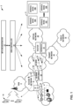
- FIG. 1 is a block diagram illustrating an example network system 2 ("network system 2") that provides network monitoring and fault localization, in accordance with the techniques described herein.
- network system 2 may represent software-defined network system.
- Network system 2 may operate as a private network to provide packet-based network services to subscriber devices 16. That is, network system 2 provides authentication and establishment of network access for subscriber devices 16 such that a subscriber device may begin exchanging data packets with public network 12, which may be an internal or external packet-based network such as the Internet.
- network system 2 comprises access network 6 that provides connectivity to public network 12 via service provider software-defined wide area network 7 (hereinafter, "SD-WAN 7") and router 8.
- SD-WAN 7 and public network 12 provide packet-based services that are available for request and use by subscriber devices 16.
- SD-WAN 7 and/or public network 12 may provide bulk data delivery, voice over Internet protocol (VoIP), Internet Protocol television (IPTV), Short Messaging Service (SMS), Wireless Application Protocol (WAP) service, or customer-specific application services.
- VoIP voice over Internet protocol
- IPTV Internet Protocol television
- SMS Short Messaging Service
- WAP Wireless Application Protocol
- Public network 12 may comprise, for instance, a local area network (LAN), a wide area network (WAN), the Internet, a virtual LAN (VLAN), an enterprise LAN, a layer 3 virtual private network (VPN), an Internet Protocol (IP) intranet operated by the service provider that operates access network 6, an enterprise IP network, or some combination thereof.
- public network 12 is connected to a public WAN, the Internet, or to other networks.
- Public network 12 executes one or more packet data protocols (PDPs), such as IP (IPv4 and/or IPv6), X.25 or Point-to-Point Protocol (PPP), to enable packet-based transport of public network 12 services.
- PDPs packet data protocols
- subscriber devices 16 connect to gateway router 8 via access network 6 to receive connectivity to subscriber services for applications hosted by public network 12 or router 8.
- a subscriber may represent, for instance, an enterprise, a residential subscriber, or a mobile subscriber.
- Subscriber devices 16 may be, for example, personal computers, laptop computers or other types of computing devices positioned behind customer equipment (CE) 11, which may provide local routing and switching functions.
- CE customer equipment
- Each of subscriber devices 16 may run a variety of software applications, such as word processing and other office support software, web browsing software, software to support voice calls, video games, video conferencing, and email, among others.
- subscriber device 16 may be a variety of network-enabled devices, referred generally to as "Internet-of-Things" (IoT) devices, such as cameras, sensors (S), televisions, appliances, etc.
- IoT Internet-of-Things
- subscriber devices 16 may comprise mobile devices that access the data services of network system 2 via a radio access network (RAN) 4.
- RAN radio access network
- Example mobile subscriber devices include mobile telephones, laptop or desktop computers having, e.g., a wireless card, wireless-capable netbooks, tablets, video game devices, pagers, smart phones, personal data assistants (PDAs) or the like.
- a network service provider operates, or in some cases leases, elements (e.g., network devices) of access network 6 to provide packet transport between subscriber devices 16 and router 8.
- Access network 6 represents a network that aggregates data traffic from one or more of subscriber devices 16 for transport to/from SD-WAN 7 of the service provider.
- Access network 6 includes network nodes that execute communication protocols to transport control and user data to facilitate communication between subscriber devices 16 and router 8.
- Access network 6 may include a broadband access network, a wireless LAN, a public switched telephone network (PSTN), a customer premises equipment (CPE) network, or other type of access network, and may include or otherwise provide connectivity for cellular access networks, such as a radio access network (RAN), e.g., RAN 4.
- RAN radio access network
- Examples include networks conforming to a 5 th Generation (5G) mobile network, Universal Mobile Telecommunications System (UMTS) architecture, an evolution of UMTS referred to as Long Term Evolution (LTE), mobile IP standardized by the Internet Engineering Task Force (IETF), as well as other standards proposed by the 3 rd Generation Partnership Project (3GPP), 3 rd Generation Partnership Project 2 (3GGP/2) and the WiMAX forum.
- 5G 5 th Generation
- UMTS Universal Mobile Telecommunications System
- LTE Long Term Evolution
- IETF Internet Engineering Task Force
- 3GPP 3 rd Generation Partnership Project
- 3GGP/2 3 rd Generation Partnership Project 2
- WiMAX forum examples include networks conforming to a 5 th Generation (5G) mobile network, Universal Mobile Telecommunications System (UMTS) architecture, an evolution of UMTS referred to as Long Term Evolution (LTE), mobile IP standardized by the Internet Engineering Task Force (IETF), as well as other standards proposed by the 3 rd Generation Partnership Project (3GPP), 3 r
- SD-WAN appliance 18 may be a customer edge (CE) router, a provider edge (PE) router, or other network device that provides connectivity between access network 6 and SD-WAN 7.
- SD-WAN 7 offers packet-based connectivity to subscriber devices 16 attached to access network 6 for accessing public network 12 (e.g., the Internet).
- SD-WAN 7 may represent a public network that is owned and operated by a service provider to interconnect a plurality of networks, which may include access network 6.
- SD-WAN 7 may implement Multi-Protocol Label Switching (MPLS) forwarding and in such instances may be referred to as an MPLS network or MPLS backbone.
- MPLS Multi-Protocol Label Switching
- SD-WAN 7 represents a plurality of interconnected autonomous systems, such as the Internet, that offers services from one or more service providers.
- Public network 12 may represent the Internet.
- Public network 12 may represent an edge network coupled to SD-WAN 7 via a transit network 22 and one or more network devices, e.g., a customer edge device such as customer edge switch or router.
- Public network 12 may include a data center.
- router 8 may exchange packets with service nodes 10 via virtual network 20, and router 8 may forward packets to public network 12 via transit network 22.
- a network service provider that administers at least parts of network system 2 typically offers services to subscribers associated with devices, e.g., subscriber devices 16, that access network system 2.
- Services offered may include, for example, traditional Internet access, VoIP, video and multimedia services, and security services.
- SD-WAN 7 may support multiple types of access network infrastructures that connect to service provider network access gateways to provide access to the offered services.
- the network system may include subscriber devices 16 that attach to multiple different access networks 6 having varying architectures.
- any one or more of subscriber devices 16 may request authorization and data services by sending a session request to a gateway device such as SD-WAN appliance 18 or router 8.
- SD-WAN appliance 18 may access a central server (not shown) such as an Authentication, Authorization and Accounting (AAA) server to authenticate the one of subscriber devices 16 requesting network access.
- AAA Authentication, Authorization and Accounting
- any of subscriber devices 16 may send subscriber data traffic toward SD-WAN 7 to access and receive services provided by public network 12, and such packets may traverse router 8 as part of at least one packet flow.
- SD-WAN appliance 18 may forward all authenticated subscriber traffic to public network 12, and router 8 may apply services 15 and/or steer particular subscriber traffic to a data center 9 if the subscriber traffic requires services on service nodes 10.
- Applications e.g., service applications
- to be applied to the subscriber traffic may be hosted on service nodes 10.
- router 8 may direct individual subscriber packet flows through services 15 executing on one or more service cards installed within router 8.
- network system 2 includes a data center 9 having a cluster of service nodes 10 that provide an execution environment for the mostly virtualized network services.
- each of service nodes 10 represents a service instance.
- Each of service nodes 10 may apply one or more services to traffic flows. As such, router 8 may steer subscriber packet flows through defined sets of services provided by service nodes 10.
- each subscriber packet flow may be forwarded through a particular ordered combination of services provided by service nodes 10, each ordered set being referred to herein as a "service chain.”
- services 15 and/or service nodes 10 may apply stateful firewall (SFW) and security services, deep packet inspection (DPI), carrier grade network address translation (CGNAT), traffic destination function (TDF) services, media (voice/video) optimization, Internet Protocol security (IPSec)/virtual private network (VPN) services, hypertext transfer protocol (HTTP) filtering, counting, accounting, charging, and/or load balancing of packet flows, or other types of services applied to network traffic.
- SFW stateful firewall
- DPI deep packet inspection
- CGNAT carrier grade network address translation
- TDF traffic destination function
- media voice/video
- IPSec Internet Protocol security
- VPN virtual private network
- HTTP hypertext transfer protocol
- subscriber packet flows may be directed along a service chain that includes any of services 15 and/or services applied by service nodes 10. Once processed at a terminal node of the service chain, i.e., the last service to be applied to packets flowing along a particular service path, the traffic may be directed to public network 12.
- a “service tunnel” or “service path” refers to a logical and/or physical path taken by packet flows processed by a service chain along with the forwarding state for forwarding packet flows according to the service chain ordering.
- Each service chain may be associated with a respective service tunnel, and packet flows associated with each subscriber device 16 flow along service tunnels in accordance with a service profile associated with the respective subscriber. For example, a given subscriber may be associated with a particular service profile, which in turn is mapped to a service tunnel associated with a particular service chain.
- SD-WAN appliance 18 may direct packet flows for the subscribers along the appropriate service tunnels, thereby causing data center 9 to apply the requisite ordered services for the given subscriber.
- SDN controller 14 may also provide a forwarding rule set to SD-WAN appliance 18 or router 8 for managing the forwarding path. In some examples, SDN controller 14 manages the forwarding path through all elements in data center 9 starting at router 8.
- service nodes 10 may implement service chains using internally configured forwarding state that directs packets of the packet flow along the service chains for processing according to the identified set of service nodes 10.
- forwarding state may specify tunnel interfaces for tunneling between service nodes 10 using network tunnels such as IP or Generic Route Encapsulation (GRE) tunnels, Network Virtualization using GRE (NVGRE), or by using VLANs, Virtual Extensible LANs (VXLANs), MPLS techniques, and so forth.
- GRE Generic Route Encapsulation
- NVGRE Network Virtualization using GRE
- VXLANs Virtual Extensible LANs
- MPLS techniques and so forth.
- real or virtual switches, routers or other network elements that interconnect service nodes 10 may be configured to direct the packet flow to the service nodes 10 according to service chains.
- network system 2 comprises a software defined network (SDN) and network functions virtualization (NFV) architecture.
- SDN controller device 14 may provide a controller for configuring and managing the routing and switching infrastructure of network system 2. While some instances described herein relate to SD-WAN appliance 18 performing the edge-based routing techniques described herein, SDN controller 14 may also perform these techniques for network system 2.
- NFV orchestrator device 13 may provide a high-level orchestrator for configuring and managing virtualization of network services into service nodes 10 of data center 9.
- SDN controller 14 manages deployment of virtual machines (VMs) within the operating environment of data center 9. For example, SDN controller 14 may interact with router 8 to specify service chain information.
- VMs virtual machines
- the service chain information provided by SDN controller 14 may specify any combination and ordering of services provided by service nodes 10, traffic engineering information for tunneling or otherwise transporting packet flows along service paths, rate limits, Type of Service (TOS) markings or packet classifiers that specify criteria for matching packet flows to a particular service chain.
- SDN controller Further example details of an SDN controller are described in WO 2013/184846 A1 ( PCT International Patent Application PCT/US13/44378, filed June 5, 2013 ).
- service nodes 10 may be network devices coupled by one or more switches or virtual switches of SD-WAN 7.
- each of service nodes 10 may run as VMs in a virtual compute environment.
- the compute environment may comprise a scalable cluster of general computing devices, such as x86 processor-based servers.
- service nodes 10 may comprise a combination of general purpose computing devices and special purpose appliances.
- virtualized network services individual network services provided by service nodes 10 can scale just as in a modern data center through the allocation of virtualized memory, processor utilization, storage and network policies, as well as horizontally by adding additional load-balanced VMs.
- service nodes 10 may be gateway devices or other routers.
- the functionality described with respect to each of service nodes 10 may be implemented in a switch, service card, or another network element or component.
- network elements within network system 2 may perform application data monitoring using various application quality of experience (QoE) metric functions.
- Example QoE metric functions include active or synthetic probing performed by nodes such as end hosts, underlay network nodes, virtual nodes, or other types of nodes.
- a network device at an edge of an access network or a data center network e.g., SD-WAN appliance 18 and router 8) can output probe packets that are transported through overlay tunnels to virtual routers in the data center and back to the network device or another network device.
- one or more network devices, virtual routers, and applications along the forwarding path of the probe packets can provide probe reporting information to SDN controller 14, which may compile and analyze the probe reporting information and present report information to customers about latency, jitter, packet-loss and any problems in the data center, as it may pertain to SLAs.
- the metrics carried by probe packets may include one or more of timestamps for sending or receiving a test packet, error estimates for sending or receiving the test packet, a sequence number for sending the test packet, a time-to-live (TTL) value for the test packet, a keepalive packet data unit (PDU), and/or a count of serviced packets, bytes, or subscribers.
- the one-way and two-way network performance measurements may include keepalive or path connectivity, round trip time (RTT), path delay, packet jitter, packet reordering, packet loss, service latency measurements, or service load measurements based on the received metrics.
- SDN controller 14 may configure the appropriate probe packet type for the node such as Internet Control Message Protocol (ICMP), User Datagram Protocol (UDP), Transmission Control Protocol (TCP), real-time performance monitoring (RPM), two-way active measurement protocol (TWAMP), IP service level agreement (IP SLA), Bidirectional Forwarding Detection (BFD), etc.
- network system 2 may include a source end host device of data center 9 that routes packets in an upstream path through an IPinIP tunnel to a core switch, which in turn routes the inner IP packet in a downstream path to a destination end host.
- SDN controller 14 may configure an end host in network system 2 to send probes using, for example, ICMP, UDP and/or TCP, to measure QoE metrics of the end-to-end path between the end hosts.
- network system 2 may include network devices (e.g., physical switches) in an underlay network (e.g., edge-to-edge in WAN network or top-of-rack (ToR) switch to ToR in a data center environment).
- SDN controller 14 may configure underlay network nodes (e.g., router 8) in network system 2 to send probes using RPM, TWAMP, IP SLA, and/or BFD to measure QoE metrics of the underlay network.
- network system 2 may include virtual nodes (e.g., virtual routers) in an overlay network.
- SDN controller 14 may configure virtual nodes in network system 2 to use natively supported probes (e.g., ICMP, UDP, and/or TCP) to measure QoE metrics of the overlay network.
- natively supported probes e.g., ICMP, UDP, and/or TCP
- network system 2 may include multiple tenants.
- each tenant may have different topologies, each with different probing requirements.
- network system 2 may include a first tenant having end host devices that use TCP to send probes, a second tenant having end host devices that use UDP to send probes, a third tenant having an underlay network device that use TWAMP to send probes, a fourth tenant having an underlay network device that use RPM to send probes, and so on.
- SDN controller 14 may implement a distributed probe selection algorithm to generate an optimized probing plan.
- SDN controller 14 may generate the probing plan based on a per tenant policy. For example, each tenant of network system 2 may have different probing policies.
- a first tenant may include a policy to measure QoE metrics between source and destination end hosts, while a second tenant may have a different policy to measure loss from WAN links in SD-WAN 7.
- the probing plan may specify an appropriate type of probe (e.g., ICMP, UDP, TWAMP, etc.) depending on the type of selected node.
- SDN controller 14 may configure the probing plan based on a probe budget per tenant.
- the probing plan may specify the number of probes (e.g., probe count) to send, the frequency at which to send the probes, the interval at which to send probes, etc.
- the frequency at which to send the probes may be determined based on whether the probe path includes wired and/or wireless links. For example, if a path to be probed includes a wireless link, the probing plan may specify sending probes at a higher frequency due to the higher possibility of loss occurring with a wireless link.
- the number of probes and interval at which to send the probes may be based on current load of probes in the network and probe traffic generated per node. For example, SDN controller 14 may configure an upper bound of probes to be sent and/or an upper bound of probe traffic sent per node.
- SDN controller 14 may implement edge-based routing to more accurately measure the various QoE metrics in the network while limiting the number of probes injected into the system.
- SDN controller 14 may coordinate and map probing processes across network system 2.
- SDN controller 14 may construct, for network system 2 that includes a plurality of different node devices, a topological representation for each tenant of network system 2.
- the topological representation may take any form (e.g., a matrix, a database, a vertex, a graphic, text, or any other data structure) that provides an indication of each of the node devices of a particular tenant and an indication of each link of a plurality of links connected to the node devices.
- SDN controller 14 may create a topological representation of any number of the networks described in network system 2.
- the topological representation could be of CEs 11 in access network 6, of subscriber devices 16, of one or more instances of SD-WAN appliance 18 in SD-WAN 7, of one or more virtual nodes in a virtualized environment in datacenter 9, or any combination thereof in an SDN system (e.g., network system 2).
- SDN controller 14 may determine the routes of the network from routing tables of the network devices.
- SDN controller 14 may determine an optimal probe assignment. For example, SDN controller 14 may use the topological representation for each tenant of the network system to determine a minimum number of paths that covers all links and select a minimum number of nodes within the paths to send probe packets. For instance, SDN controller 14 may apply an optimization algorithm, e.g., greedy algorithm-based heuristic, to the topological representation to compute the probe paths and to select nodes within the paths to send probe packets.
- An example of applying a greedy algorithm to a path matrix is illustrated and described below: Table I. Path Matrix Link 1 Link 2 Link 3 Path 1 1 1 0 Path 2 1 0 1 Path 3 0 0 1
- SDN controller 14 may apply a greedy algorithm to determine the minimum number of paths that covers link 1, link 2, and link 3. In this example, sending probes on path 1 and path 2 would cover all the links in the network. SDN controller 14 may determine a minimum number of nodes within path 1 and path 2 to send probe packets.
- the nodes may be selected based on static configuration (e.g., user configuration) of particular nodes to send the probes or a hybrid of both static configuration and heuristic based algorithms.
- the nodes selected to send probe packets may be referred to herein as "probe generators" and the nodes selected to respond to the probe packets may be referred to herein as “probe responders.”
- a probe generator may perform the active or synthetic probing functions while nodes that are not configured as probe generators do not send probe packets. In this way, only the selected nodes are configured to send probe packets.
- SDN controller 14 may use a probe intent data model to configure the probe generators and/or probe responders. For example, SDN controller 14 may translate a high-level probe intent data model (e.g., user intent-based network or data models) that defines the probe intent at a high-level (e.g., with more generality) into a lower-level probe configuration data model that defines platform specific configuration used to configure particular endpoints (e.g., end host, underlay network device, virtual node) to use appropriate probe packets. For example, a user may define a high-level probe intent data model to detect latency anomalies in WAN links within SD-WAN 7.
- a high-level probe intent data model e.g., user intent-based network or data models
- SDN controller 14 may identify the node type as an underlay network device (e.g., SD-WAN appliance 18) and may translate the high-level probe intent data model into a lower-level probe configuration data model to configure SD-WAN appliance 18 to send probes using TWAMP, for example, to measure latency metrics of the WAN links within SD-WAN 7.
- a user may define a high-level probe intent data model to detect anomalies in data center 9 that deploys virtual machines.
- SDN controller 14 may identify the node type as a virtual node (e.g., virtual router) and may translate the high-level probe intent data model into a lower-level probe configuration data model to configure the virtual router to send probes using ICMP, for example.
- the lower-level probe configuration data model may specify, for example, a network address (e.g., IP address) of the probe generator and a network address of the probe responder.
- the lower-level probe configuration data model may also specify the number of probes to send, an interval at which to send the probes, and/or the frequency at which to send the probes.
- the selected nodes configured as probe generators send probes on various paths in the network.
- the probe packets may be generated and analyzed by various components of a node, such as agents of end hosts and/or virtual nodes.
- SDN controller 14 may receive, from the selected nodes, one or more QoE metrics and may use the one or more QoE metrics to determine whether paths in the network have any problems (e.g., anomalies).
- white box monitoring is used to monitor applications running on a server.
- each network node is queried for its performance metrics, which is not effective as statistics of the nodes may be error prone or unavailable during their current failure states.
- black-box monitoring send end-to-end probes that are unable to identify a specific link or node that is the root cause of the problem, and requires additional manual troubleshooting to pinpoint the source of the problem.
- SDN controller 14 may detect anomalies along probe paths and perform fault localization to pinpoint a node or link causing the anomalies.
- a user may specify a high-level probe intent data model to detect latency anomalies between router 8 and subscriber devices 16.
- SDN controller 14 may configure router 8 to send probe 31 on path 30 to measure latency from router 8 to a mobile subscriber device 16.
- SDN controller 14 may configure router 8 to send probe 33 on path 32 to measure latency from router 8 to another one of subscriber devices 16.
- SDN controller 14 may configure router 8 to send probe 35 on path 34 to measure latency from router 8 to another one of subscriber devices 16.
- SDN controller 14 may receive latency metrics measured from probes 31, 33, and 35, and evaluate the latency metrics with a computed baseline latency value to detect for anomalies in the probing paths.
- SDN controller 14 receives QoE metrics for each tenant of network system 2 and aggregates the QoE metrics for each tenant to compute a set of QoE metrics and evaluates the set of QoE metrics with a computed baseline value.
- the baseline value may be computed from historical data of the QoE metrics and may be dynamically updated as QoE metrics are updated.
- the baseline value may be statically configured.
- the baseline latency value may be computed based on latency metrics previously measured on paths 30, 32, and 34 or statically configured by a user.
- the computed baseline value may be a threshold, a range, or any value to determine whether the metrics meet the baseline value or whether the metrics deviate from the baseline value (i.e., an anomaly).
- SDN controller 14 may determine if the plurality of paths have an intersection, e.g., any overlapping links. If the plurality of paths have at least one overlapping link, SDN controller 14 determines whether the at least one overlapping link is the root cause of the anomalies. The root cause determination may depend on the type of QoE metric measured and/or whether the links of the paths include a wireless link.
- SDN controller 14 may determine paths 32 and 34 each have a latency anomaly and determines that paths 32 and 34 have at least one overlapping link, e.g., a WAN link in SD-WAN 7. In this example, if the latency metric for each of paths 32 and 34 deviates from the baseline latency value, SDN controller 14 may determine that the overlapping WAN link may be the root cause of the anomalies.
- SDN controller 14 may determine whether the paths include wired or wireless links when determining the root cause of the anomalies.
- path 30 may include a wireless link
- path 32 may include a wired link.
- SDN controller 14 may receive a first loss metric for path 30 and a second loss metric for path 32 and determine that each of paths 30 and 32 include an anomaly.
- SDN controller 14 determines that path 30 includes a wireless link. If the first loss metric for path 30 deviates from the second loss metric for path 32, SDN controller 14 may determine that the wireless link is a candidate for the root cause of the anomaly because a wireless link is more likely to drop packets and thus likely to be the cause of the packet loss. SDN controller 14 may then configure the edge node to the wireless link to send an additional probe, e.g., probe 37, on the wireless link to determine if the wireless link is in fact the root cause of the anomaly.
- an additional probe e.g., probe 37
- FIG. 2 is a block diagram illustrating an example SD-WAN 207, in accordance with one or more techniques described in this disclosure.
- SD-WAN 207 in FIG. 2 may represent an example instance of SD-WAN 7 in FIG. 1 .
- SD-WAN 207 includes three different WAN links: a first WAN link 240 coupling SD-WAN appliance 218 to a Multi-Protocol Layer Switching (MPLS) network 250, a second WAN link 242 coupling SD-WAN appliance 218 to Internet 252, and a third WAN link 244 coupling SD-WAN appliance 218 to a mobile network 254 (e.g., LTE/5G).
- MPLS Multi-Protocol Layer Switching
- SD-WAN 207 may include any number of links of any suitable type for transmitting data flows between the client side (e.g., client device 216 and SD-WAN appliance 218) and the application side (e.g., SD-WAN appliance 256 and application server 258).
- controller 214 may configure any type of node, e.g., client device 216, SD-WAN appliance 218, SD-WAN appliance 256, and/or application server 258 to send an appropriate type of probe packet to measure QoE metrics.
- controller 214 may configure client device 216 may send probes 231 and 233 along end-to-end paths between client device 216 and application server 258.
- client device 216 may represent an end host.
- controller 214 may configure client device 216 to send an appropriate type of probe (e.g., ICMP echo, UDP ping, or TCP ping) to measure QoE metrics along the end-to-end path to application server 258.
- an appropriate type of probe e.g., ICMP echo, UDP ping, or TCP ping
- SDN controller 214 may detect anomalies along paths measured by probes 231, 233 and perform fault localization to pinpoint a node or link causing the anomalies.
- SDN controller 214 may configure client device 218 to send probe 231 on a first end-to-end path to application server 258 using a WAN link in SD-WAN 207 and configure client device 218 to send probe 233 a second end-to-end path to application server 258 also using a WAN link in SD-WAN 207.
- probe 231 such as a TCP ping
- probe 233 is sent on the second end-to-end path also including WAN link 242.
- SDN controller 214 may receive QoE metrics measured from probes 231 and 233, and evaluate the latency metrics with a computed baseline latency value to detect for anomalies in the probing paths.
- SDN controller 214 may determine each of the paths has a latency anomaly and determines that the paths have an intersection, e.g., WAN link 242 in SD-WAN 207. In this example, if the latency metric for each of the paths deviates from the baseline latency value, SDN controller 214 may determine that the overlapping WAN link 242 may be the root cause of the latency anomaly.
- SDN controller 214 may, in some examples, determine the type of metric being measured and whether the paths include wired or wireless links when determining the root cause of the anomalies.
- one of the paths measured by probes 231 and 233 may include a wireless link (e.g., coupling SD-WAN appliance 218 to client device 216.
- SDN controller 214 may receive loss metrics and determine that one of the paths includes a wireless link.
- SDN controller 214 may determine that the wireless link between SD-WAN appliance 218 and client device 216 is a candidate for the root cause of the anomaly (in addition to or as an alternative to WAN link 242).
- SDN controller 214 may then configure the edge node to the wireless link, e.g., SD-WAN appliance 218, to send an additional probe on the wireless link to determine if the wireless link is in fact the root cause of the anomaly.
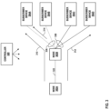
- FIG. 3 is a conceptual diagram illustrating an example operation of fault localization, in accordance with the techniques described in this disclosure.
- FIG. 3 includes nodes 302A-302B (collectively, “nodes 302") and subscriber devices 304A-304D (collectively, "subscriber devices 304").
- Nodes 302 may represent any node in network system 2 of FIG. 1 , such as an end host, an underlay network device, and/or a virtual node.
- Subscriber devices 304 may represent any of subscriber devices 16 of FIG. 1 .
- subscriber devices 304A and 304B are connected to node 302B via wireless links 306, respectively.
- Subscriber devices 304C and 304D are connected to node 302B via wired links 308, respectively.
- controller 320 may configure node 302A to send probes along paths to subscriber devices 304.
- node 302A sends probe 310 to measure one or more QoE metrics for an end-to-end path from node 302A to subscriber device 304A.
- probe 310 may measure a loss metric and/or a latency metric.
- node 302A sends probe 312 to measure one or more QoE metrics for an end-to-end path from node 302A to subscriber device 304D.
- probe 312 may also measure a loss metric and/or a latency metric.
- SDN controller 320 receives a latency metric from each of probes 310 and 312 and determines if the paths measured by probes 310 and 312 have an anomaly.
- SDN controller 320 may compute baseline latency value of 40 milliseconds (ms). If probe 310 measures a latency of 100ms and probe 312 measures a latency of 120ms, SDN controller 320 may determine each of the paths has an anomaly because the measured latency deviates from the baseline latency value. In response to determining that the paths measured by probes 310 and 312 have an anomaly, SDN controller 320 may determine an intersection (e.g., overlapping link) of the paths. In this example, link 322 is shared between the paths.
- SDN controller 320 determines whether link 322 is the root cause of the latency anomaly. In this example, if the latency metric from probes 310 and 312 deviates from the baseline latency value, then SDN controller 320 determines that shared link 322 is the root cause of the latency anomaly. In some examples, SDN controller 320 may determine whether the measured metrics deviate from the baseline value based on a threshold. The threshold may be user defined or configured through machine learning.
- controller 320 receives the loss metrics from probes 310 and 312 and determines if the paths measured by probes 310 and 312 have an anomaly.
- SDN controller 320 may compute a baseline loss value. If probe 310 and probe 312 both measure a loss that deviates from the baseline loss value, SDN controller 320 may, given that the metric is a loss metric, determine whether the paths measured by probes 310 and 312 include a wireless link. As a wireless link is a likely cause of packet loss, SDN controller 320 may determine that the wireless link (e.g., wireless link 306 connecting node 302B and subscriber device 304A) is a possible root cause of the loss anomaly (in addition to or as an alternative to shared link 322).
- the wireless link e.g., wireless link 306 connecting node 302B and subscriber device 304A
- SDN controller may configure the edge computing device, e.g., node 302B, to send an additional probe packet, e.g., probe packet 314, to measure the loss metric on the wireless link to determine whether the wireless link is the root cause of the loss anomaly.
- edge computing device e.g., node 302B
- probe packet 314 to measure the loss metric on the wireless link to determine whether the wireless link is the root cause of the loss anomaly.
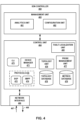
- FIG. 4 is a block diagram illustrating the example SDN controller configured to implement the techniques described herein.
- SDN controller 460 creates a topological representation of the network that contains or is managed by SDN controller 460 in order to efficiently create an overall process for probing the various links within the network.
- SDN controller 460 may operate as a network services controller for a service provider network.
- SDN controller 460 includes a management unit 465, a control unit 464 for controlling operation of SDN controller 460, and a network interface 466 for exchanging packets with network devices by inbound link 467 and outbound link 468.
- control unit 464 and/or management unit 465 may be implemented as one or more processes executing on one or more virtual machines of one or more physical computing devices. That is, while generally illustrated and described as executing on a single SDN controller 460, aspects of each of these units may be delegated to or distributed across other computing devices.
- control unit 464 and/or management unit 465 may include one or more processors (not shown) that execute software instructions, such as those used to define a software or computer program, stored to a computer-readable storage medium (not shown), such as non-transitory computer-readable mediums including a storage device (e.g., a disk drive, or an optical drive) or a memory (such as Flash memory or RAM) or any other type of volatile or non-volatile memory, that stores instructions to cause the one or more processors to perform the techniques described herein.
- a computer-readable storage medium such as non-transitory computer-readable mediums including a storage device (e.g., a disk drive, or an optical drive) or a memory (such as Flash memory or RAM) or any other type of volatile or non-volatile memory, that stores instructions to cause the one or more processors to perform the techniques described herein.
- each of control unit 464 and/or management unit 465 may comprise dedicated hardware, such as one or more integrated circuits, one or more application-specific integrated circuits (ASICs), one or more Application Specific Special Processors (ASSPs), one or more FPGAs, or any combination of one or more of the foregoing examples of dedicated hardware, for performing the techniques described herein.
- ASICs application-specific integrated circuits
- ASSPs Application Specific Special Processors
- FPGAs field-programmable gate arrays
- Management unit 465 may comprise a management layer of SDN controller 460, whereas control unit 464 may comprise a control layer of SDN controller 460.
- Management unit 465 includes an analytics unit 461 and a configuration unit 462.
- Analytics unit 461 may capture information from physical and/or virtual network elements within an SD-WAN system (e.g., network system 2 of FIG. 1 ), e.g., a gateway, service nodes 10, or of each data center 9 of FIG. 1 , and analyze the information for use in managing the network services offered by the service provider.
- the information may include statistics, logs, events, and errors.
- Configuration unit 462 stores configuration information for the network elements within the SD-WAN system.
- the configuration information comprises a virtual network configuration.
- Configuration unit 462 may translate a high-level data model of the intended virtual network configuration to a lower-level data model for use in interacting with the network elements.
- Control unit 464 of SDN controller 260 implements a centralized control plane for the SD-WAN system that is responsible for maintaining a constantly changing network state. Control unit 464 interacts with the network elements within the SD-WAN system to maintain a consistent network state across all of the network elements. Control unit 464 provides an operating environment for a command line interface daemon 475 ("CLI 475") that provides an interface by which an administrator or other management entity may modify the configuration of SDN controller 460 using text-based commands. Control unit 464 also provides an operating environment for several protocols 470, including Border Gateway Protocol (BGP) 472 and Extensible Messaging and Presence Protocol (XMPP) 474 as illustrated in the example of FIG. 4 .
- Border Gateway Protocol BGP
- XMPP Extensible Messaging and Presence Protocol
- These commands may alter which QoE metrics are to be measured, how SDN controller 460 constructs the topology of the network, and whether SDN controller 460 optimizes the distribution of the probing processes being performed across the node devices.
- the user configuration e.g., intent-based configuration
- control unit 264 uses XMPP 274 to communicate with network elements within the SD-WAN system (e.g., router 8, subscriber devices 16, or service nodes 10 of data center 9 within network system 2 of FIG. 1 ), by an XMPP interface (not shown).
- Virtual network route data, statistics collection, logs, and configuration information may be sent as extensible markup language (XML) documents in accordance with XMPP 474 for communication between SDN controller 460 and the network elements.
- Control unit 464 may also use XMPP 474 to communicate with one or both of analytics unit 461 and configuration unit 462 of SDN controller 460.
- Control unit 464 further includes device manager 471, topology unit 476, probe management unit 477, topology database 478, and metric database 479, which enables control unit 464 to construct a topological representation of the nodes, links, and probing processes to develop a full probing plan across the topology of the network.
- SDN controller 460 may be a cloud controller for a network, coordinating and mapping probing processes across the network.
- topology unit 476 may construct, for the network that includes a plurality of node devices (e.g., subscriber devices and service nodes), a topological representation of the network.
- the topological representation may take any form (e.g., a matrix, a database, a graphic, text, or any other data structure) that provides an indication of each of the node devices and an indication of each link of a plurality of links, where each link connects two of the node devices.
- the topological representation may be stored in topology database 478.
- topology unit 476 may translate high-level data models associated with a topology of the network into lower-level models suitable for interacting with network elements or devices, such as the network devices shown in FIGS. 1-3 .
- topology unit 476 may receive, via network interface 466, high-level data models (e.g., user intent-based network or data models) from an orchestration engine and/or an administrator. These models may be associated with a topology of a network. Topology unit 476 may use these models and intent to construct the topological representation to store within topology database 478.
- high-level data models e.g., user intent-based network or data models
- topology unit 476 may monitor one or more probe packets sent over each of the plurality of links. For instance, when the techniques described herein are first applied to the network, each node device may be sending probe packets over each of the node device's respective links. However, topology unit 476 may not inherently possess a data structure that depicts which node devices are in the network, and which other node devices each node device is linked to. By monitoring the various probe packets sent across the network, topology unit 476 may populate a data structure, such as an adjacency matrix, with an indication of which node devices are in the network, and which other node devices each node device is sending probe packets to.
- a data structure such as an adjacency matrix
- the network may be configured such that each node device is performing the probing function for each link connected to the node device, this monitoring function would provide topology unit 476 with a complete representation of the various connections within the network, and topology unit 476 may use graph theory to derive the topological representation of the various node devices and links within the network.
- probe management unit 477 may determine, based on the topological representation of the network, a minimum number of paths that covers all links and a minimum number of nodes within the paths to send probe packets. For example, when selecting the node devices for probing on respective links, probe management unit 477 may perform an optimization algorithm (e.g., greedy algorithm).
- an optimization algorithm e.g., greedy algorithm
- topology unit 476 and probe management unit 477 may be configured to repeat the processes described herein whenever a new node device enters the system or whenever a current node device leaves the system.
- probe management unit 477 may receive, from the selected node device, a one or more QoE metrics for the path.
- Probe management unit 477 may store the QoE metrics in metric database 479, such that the QoE metrics may be referenced in further extrapolations and estimations for other links and/or paths.
- Device manager 475 may generate vendor-agnostic device information based on the inputs provided by topology database 478 and metrics database 479. Vendor-agnostic device information may also be referred to as device abstract configuration information. Vendor-agnostic device information is agnostic, per-device configuration information for each individual network device in a network. In some examples, vendor-agnostic device information may comprise Extensible Markup Language (XML) schema or Yet Another Next Generation (YANG) schema information.
- XML Extensible Markup Language
- YANG Yet Another Next Generation
- SDN controller 460 may then utilize device manager 471 to implement one or more translation processes to translate vendor-agnostic device information into vendor-specific device information.
- Vendor-specific device information may also be referred to as vendor specific, or concrete, device configuration information.
- Each individual network device in the network may have both vendor-agnostic device information and vendor-specific device information.
- vendor-specific device information may be customizable via the use, e.g., of Jinja2 templates for each different vendor.
- device manager 471 may be configured to generate both vendor-agnostic device information and vendor-specific device information in the manner illustrated in FIG. 4 .
- Vendor-agnostic device information may include vendor-agnostic device configuration and/or command information (e.g., entered via CLI 475 or other management interface), and vendor-specific device information may include vendor-specific device configuration and/or command information, as well (e.g., sent via network interface 466 and/or via protocols 470).
- SDN controller 460 illustrated in FIG. 4 may send vendor-specific device information to individual network devices for which the vendor-specific device information has been generated.
- SDN controller 460 may provide vendor-specific device configuration information to a network device via a configuration interface, and may provide vendor-specific device command information to a network device via a command interface.
- vendor-specific device configuration information and vendor-specific device command information may each be included in vendor-specific device information, which is translated from vendor-agnostic device information. Additional information regarding translation of high-level configuration instructions to low-level device configuration can be found in U.S. Patent 10,200,248 ( US Application Serial No. 15/198,657), filed June 30, 2016 , and entitled TRANSLATING HIGH-LEVEL CONFIGURATION INSTRUCTIONS TO LOW-LEVEL DEVICE CONFIGURATION.
- probe management unit 477 may create a dynamic representation of the QoE metrics for each link and each possible connection, in all directions, in topology database 478 and metrics database 479. For instance, probe management unit 477 may store the received measurements for each link in metrics database 479. Then, for each extrapolation/estimation (e.g., for each reverse direction of the received QoE metrics, for each logical path connecting two node devices also connected by a link, and for each complex path that is a shortest path between two node devices not connected directly by a link) indicated in topology database 478, probe management unit 477 may store the respective estimated QoE metrics in metrics database 79. This information may be updated as new metrics are received by probe management unit 477. With this information, whenever SDN controller 460 must make a routing decision for application traffic or for traffic between nodes, SDN controller 460 may reference topology database 478 and the QoE metrics stored within metrics database 479 to make routing decisions for the traffic within the network.
- SDN controller 460 is one example instance of a controller configured to perform the techniques described in this disclosure.
- SDN controller 460 may include additional units to perform various functions, such as an alarm unit (not shown) to alert users.
- SDN controller 460 includes fault localization unit 480 to pinpoint the node or link causing the one or more anomalies.
- SDN controller 460 may receive QoE metrics via network interface 466 from selected nodes in the network.
- Fault localization unit 480 may evaluate the QoE metrics with a computed baseline value to detect for anomalies in the probing paths.
- the computed baseline value may be computed from historical data of the QoE metrics, e.g., QoE metrics stored in metrics database 479, and may be dynamically updated as QoE metrics are updated.
- a user may use CLI 475 to statically configure a computed baseline value.
- Fault localization unit 480 may evaluate the received QoE metrics with the computed baseline value to detect for anomalies in the probing paths. If fault localization unit 480 determines that a plurality of paths have anomalies, fault localization unit 480 may determine if the plurality of paths have an intersection, e.g., any overlapping links. For example, fault localization unit 480 may determine from topology database 478 if the probing paths have an intersection (e.g., an overlapping link). In response to determining that the probing paths include an overlapping link, fault localization unit 480 determines whether the at least one overlapping link is the root cause of the anomalies.
- fault localization unit 480 may determine whether the QoE metrics for the measured paths deviate from the baseline value. If each of the QoE metrics for the measured paths deviate from the baseline value, then fault localization unit 480 determines that the overlapping link is the root cause of the anomaly.
- fault localization unit 480 may determine whether the paths include wired or wireless links when determining the root cause of the anomalies. Fault localization unit 480 may determine that the QoE metric is a loss metric. In this example, fault localization unit 480 may determine from topology database 478 whether the probing paths include a wireless link (e.g., whether a link uses wireless protocols). If fault localization unit 480 determines the paths include a loss anomaly, fault localization unit 480 may, given that the metric is a loss metric, determine whether the paths measured by the probes include a wireless link.
- fault localization unit 480 may determine that the wireless link (e.g., wireless link 306 connecting node 302B and subscriber device 304A of FIG. 3 ) is a possible root cause of the loss anomaly (in addition to or as an alternative to shared link 322). To determine whether the wireless link is the root cause of the packet loss, fault localization unit 480 may configure the edge computing device to the wireless link to send an additional probe packet on the wireless link to determine whether the wireless link is the root cause of the loss anomaly.
- the wireless link e.g., wireless link 306 connecting node 302B and subscriber device 304A of FIG. 3
- fault localization unit 480 may configure the edge computing device to the wireless link to send an additional probe packet on the wireless link to determine whether the wireless link is the root cause of the loss anomaly.
- SDN controller 14 may determine if the plurality of paths have an intersection, e.g., any overlapping links. If the plurality of paths have at least one overlapping link, SDN controller 14 determines whether the at least one overlapping link is the root cause of the anomalies. The root cause determination may depend on the type of QoE metric measured and/or whether the links of the paths include a wireless link.
- SDN controller 14 may determine paths 32 and 34 each have a latency anomaly and determines that paths 32 and 34 have at least one overlapping link, e.g., a WAN link in SD-WAN 7. In this example, if the latency metric for each of paths 32 and 34 deviates from the baseline latency value, SDN controller 14 may determine that the overlapping WAN link may be the root cause of the anomalies.
- SDN controller 14 may determine whether the paths include wired or wireless links when determining the root cause of the anomalies.
- path 30 may include a wireless link
- path 32 may include a wired link.
- SDN controller 14 may receive a first loss metric for path 30 and a second loss metric for path 32 and determine that each of paths 30 and 32 include an anomaly.
- SDN controller 14 determines that path 30 includes a wireless link. If the first loss metric for path 30 deviates from the second loss metric for path 32, SDN controller 14 may determine that the wireless link is a candidate for the root cause of the anomaly because a wireless link is more likely to drop packets and thus likely to be the cause of the packet loss. SDN controller 14 may then configure the edge node to the wireless link to send an additional probe, e.g., probe 37, on the wireless link to determine if the wireless link is in fact the root cause of the anomaly.
- an additional probe e.g., probe 37
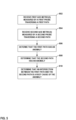
- FIG. 5 is a flow diagram illustrating an example technique for a software-defined wide area network system that performs probe assignment functions based on a topological representation of the network, in accordance with the techniques of this disclosure.
- the example operation is described with respect to SDN controller 320 from FIG. 3 , for example, but may represent any SDN controller described in this disclosure.
- the following are steps of the process, although other examples of the process performed in the techniques of this disclosure may include additional steps or may not include some of the below-listed steps.
- SDN controller 320 receives a first one or more QoE metrics measured by a first probe traversing a first path comprising one or more links (502). For example, SDN controller 320 may configure node 302A to send probe 310 on a first end-to-end path between node 302A and subscriber device 304A to measure QoE metrics (e.g., latency and loss). SDN controller 320 receives the latency metric and loss metric for the path between node 302A and subscriber device 304A. Similarly, SDN controller 320 may configure node 302A to send probe 312 on a second end-to-end path between node 302A and subscriber device 304D to measure QoE metrics (e.g., latency and loss).
- QoE metrics e.g., latency and loss
- SDN controller 320 receives a second one or more QoE metrics measured by a second probe traversing a second path comprising one or more links (504). For example, SDN controller 320 may configure node 302A to send probe 312 on a second end-to-end path between node 302A and subscriber device 304D to measure QoE metrics (e.g., latency and loss). SDN controller 320 receives the latency metric and loss metric for the path between node 302A and subscriber device 304D.
- QoE metrics e.g., latency and loss
- SDN controller 320 determines, from the first set of QoE metrics, that the first path has an anomaly (506) and determines, from the second set of QoE metrics, that the second path has an anomaly (508). For example, SDN controller 320 may compute a baseline latency value of 40 milliseconds (ms). If probe 310 measures a latency of 100ms and probe 312 measures a latency of 120ms, SDN controller 320 may determine each of the paths has an anomaly because the measured latency deviates from the baseline latency value.
- SDN controller 320 determines, in response to determining the first path has an anomaly and the second path has an anomaly, an intersection between the first path and the second path (510). For example, in response to determining that the latency metric measured by probes 310 and 312 each deviates from the baseline latency value, SDN controller 320 determines an intersection (e.g., overlapping link 322) between the paths is a root cause of the latency anomaly.
- SDN controller 320 may determine whether the paths include wired or wireless links when determining the root cause of the anomalies. As one example, SDN controller 320 may compute a baseline loss value. If probe 310 and probe 312 both measure a loss that deviates from the baseline loss value, SDN controller 320 may, given that the metric is a loss metric, determine whether the paths measured by probes 310 and 312 include a wireless link. As a wireless link is a likely cause of packet loss, SDN controller 320 may determine that the wireless link (e.g., wireless link 306 connecting node 302B and subscriber device 304A) is a possible root cause of the loss anomaly (in addition to or as an alternative to shared link 322).
- the wireless link e.g., wireless link 306 connecting node 302B and subscriber device 304A
- SDN controller 320 may configure the edge computing device, e.g., node 302B, to send an additional probe packet, e.g., probe packet 314, to measure the loss metric on the wireless link to determine whether the wireless link is the root cause of the loss anomaly.
- FIG. 6 is a block diagram illustrating an example of a distributed controller, in accordance with the techniques described in this disclosure.
- controller 600 may represent controller 14 of FIG. 1 or any controller of a plurality of network devices.
- FIG. 6 illustrates an example edge computing architecture that includes different types of edge nodes from a core network 602 to a customer device, each with different metric (e.g., latency) requirements.
- links can be wired or wireless.
- customer edge nodes 614A-614N may have wireless connectivity with subscriber devices 616A-616N (collectively, "subscriber devices 608").
- subscriber devices 616A-616N collectively, “subscriber devices 608"
- customer edge nodes 614 may represent an edge device for a 5G network or telephone company (“telco") network.
- telco telephone company
- the last hop may include a wireless link to 5G enabled devices, such as subscriber devices 616.
- edge nodes There are different latency requirements at different levels of edge nodes.
- a node in the near edge network (e.g., 604A) may be responsible for managing edge nodes in a given geographical region.
- a distributed probe controller e.g., controller 600 will be used to configure probes for different nodes as probe generators.
- controller 600 will be used to configure probes for different nodes as probe generators.
- probe controller instances may be instantiated at different levels of edge nodes, each instance of the probe controller being responsible for configuring probes for its downstream and upstream network paths.
- a probe controller instance e.g., near edge probe controller 610A
- near edge probe controller 610N may be instantiated at near edge network 604N
- far edge probe controller 612 may be instantiated at far edge network 606A.
- a probe controller instance at "near edge,” such as near edge probe controller 610A-610N may be responsible for configuring probes for paths to "far edge” nodes in the same region.
- controller instances at "far edge,” e.g., far edge probe controller 612 may be responsible for configuring probes to customer edge nodes and end devices.
- Analysis of the probe results for root cause may be performed at different edge nodes in a distributed manner. For example, the "far edge" site may perform root cause analysis of any failure in the downstream network for which it is responsible.
- a controller comprises one or more processors operably coupled to a memory configured to: receive a first one or more Quality of Experience (QoE) metrics measured by a first probe traversing a first path comprising one or more links; receive a second one or more QoE metrics measured by a second probe traversing a second path comprising one or more links; determine, from the first one or more QoE metrics, that the first path has an anomaly; determine, from the second one or more QoE metrics, that the second path has an anomaly; and determine, in response to determining the first path and the second path has an anomaly, based on the type of metrics and the type of links, that an intersection between the first path and the second path is a root cause of the anomaly.
- QoE Quality of Experience
- the techniques described herein may be implemented in hardware, software, firmware, or any combination thereof.
- Various features described as modules, units or components may be implemented together in an integrated logic device or separately as discrete but interoperable logic devices or other hardware devices.
- various features of electronic circuitry may be implemented as one or more integrated circuit devices, such as an integrated circuit chip or chipset.
- this disclosure may be directed to an apparatus such as a processor or an integrated circuit device, such as an integrated circuit chip or chipset.
- an apparatus such as a processor or an integrated circuit device, such as an integrated circuit chip or chipset.
- the techniques may be realized at least in part by a computer-readable data medium comprising instructions that, when executed, cause a processor to perform one or more of the methods described above.
- the computer-readable data medium may store such instructions for execution by a processor.
- a computer-readable medium may form part of a computer program product, which may include packaging materials.
- a computer-readable medium may comprise a computer data storage medium such as random access memory (RAM), read-only memory (ROM), non-volatile random access memory (NVRAM), electrically erasable programmable read-only memory (EEPROM), Flash memory, magnetic or optical data storage media, and the like.
- RAM random access memory
- ROM read-only memory
- NVRAM non-volatile random access memory
- EEPROM electrically erasable programmable read-only memory
- Flash memory magnetic or optical data storage media, and the like.
- an article of manufacture may comprise one or more computer-readable storage media.
- a computer-readable medium may also or alternatively comprise a transient medium such as a transmission signal or carrier wave. Such transient media may be used to convey instructions between components of a single computer system and/or between multiple separate computer systems.
- the computer-readable storage medium may comprise non-transitory media.
- the term "non-transitory” may indicate that the storage medium is not embodied in a carrier wave or a propagated signal.
- a non-transitory storage medium may store data that can, over time, change (e.g., in RAM or cache).
- the code or instructions may be software and/or firmware executed by processing circuitry including one or more processors, such as one or more digital signal processors (DSPs), general purpose microprocessors, application-specific integrated circuits (ASICs), field-programmable gate arrays (FPGAs), or other equivalent integrated or discrete logic circuitry.
- DSPs digital signal processors
- ASICs application-specific integrated circuits
- FPGAs field-programmable gate arrays
- processors may refer to any of the foregoing structure or any other structure suitable for implementation of the techniques described herein.
- functionality described in this disclosure may be provided within software modules or hardware modules.
Landscapes
- Engineering & Computer Science (AREA)
- Computer Networks & Wireless Communication (AREA)
- Signal Processing (AREA)
- Environmental & Geological Engineering (AREA)
- Quality & Reliability (AREA)
- Health & Medical Sciences (AREA)
- Cardiology (AREA)
- General Health & Medical Sciences (AREA)
- Computer Vision & Pattern Recognition (AREA)
- Data Exchanges In Wide-Area Networks (AREA)
Claims (9)
- Verfahren, das Folgendes umfasst:Empfangen (502), durch eine softwaredefinierte Vernetzungssteuereinheit (Software-Defined Networking Controller, SDN-Steuereinheit) für ein Netz, das mehrere Knotenvorrichtungen enthält, von ersten Werten für eine oder mehrere Erfahrungsqualität, QoE (Quality of Experience), -Metriken, die von einer ersten Sonde gemessen werden, die einen ersten Pfad durchläuft, wobei der erste Pfad von einer bestimmten Knotenvorrichtung der mehreren Knotenvorrichtungen ausgeht und eine oder mehrere Verbindungen umfasst;Empfangen (504), durch die SDN-Steuereinheit, von zweiten Werten für die ein oder mehreren QoE-Metriken, die von einer zweiten Sonde gemessen werden, die einen zweiten Pfad durchläuft, wobei der zweite Pfad von der bestimmten Knotenvorrichtung der mehreren Knotenvorrichtungen ausgeht und eine oder mehrere Verbindungen umfasst;Bestimmen (506), durch die SDN-Steuereinheit und anhand der ersten Werte für die ein oder mehreren QoE-Metriken, dass der erste Pfad eine Anomalie aufweist, wobei das Bestimmen, ob der erste Pfad eine Anomalie aufweist, das Auswerten der ersten Werte für die ein oder mehreren QoE-Metriken relativ zu Basiswerten für die ein oder mehreren QoE-Metriken umfasst;Bestimmen (508), durch die SDN-Steuereinheit und anhand der zweiten Werte für die ein oder mehreren QoE-Metriken, dass der zweite Pfad eine Anomalie aufweist, wobei das Bestimmen, ob der zweite Pfad eine Anomalie aufweist, das Auswerten der zweiten Werte für die ein oder mehreren QoE-Metriken relativ zu den Basiswerten für die ein oder mehreren QoE-Metriken umfasst;Bestimmen, durch die SDN-Steuereinheit, eines Typs von Metriken der ein oder mehreren QoE-Metriken, und eines Typs von Verbindungen der ein oder mehreren Verbindungen des ersten Pfades und der ein oder mehreren Verbindungen des zweiten Pfades; undBestimmen (510), durch die SDN-Steuereinheit und in Reaktion auf das Bestimmen, dass der erste Pfad und der zweite Pfad eine Anomalie aufweisen, basierend auf dem Typ der Metriken und dem Typ der Verbindungen, dass ein Schnittpunkt zwischen dem ersten Pfad und dem zweiten Pfad eine Grundursache der Anomalie ist, wobei der Schnittpunkt eine überlappende Verbindung zwischen den ein oder mehreren Verbindungen des ersten Pfades und den ein oder mehreren Verbindungen des zweiten Pfades umfasst, und wobei das Bestimmen, dass der Schnittpunkt die Grundursache der Anomalie ist, das Bestimmen umfasst, dass die ersten Werte für die ein oder mehreren QoE-Metriken und die zweiten Werte für die ein oder mehreren QoE-Metriken jeweils von dem Basiswert abweichen.
- Verfahren nach Anspruch 1, wobei der Basiswert aus einem oder mehreren historischen Werten für die QoE-Metriken für den ersten und den zweiten Pfad berechnet wird.
- Verfahren nach einem der Ansprüche 1-2, wobei der Basiswert statisch ausgelegt ist.
- Verfahren nach einem der Ansprüche 1-3,
wobei das Bestimmen, dass der Schnittpunkt die Grundursache der Anomalie ist, ferner umfasst:
in Reaktion auf das Bestimmen, dass der Typ von Metrik eine Verlustmetrik ist und die ein oder mehreren Verbindungen des ersten Pfades oder die ein oder mehreren Verbindungen des zweiten Pfades eine drahtlose Verbindung beinhalten, Bestimmen, dass die drahtlose Verbindung ein Kandidat als Grundursache der Anomalie ist. - Verfahren nach Anspruch 4, das ferner Folgendes umfasst:
Senden, durch die SDN-Steuereinheit, einer dritten Sonde auf der drahtlosen Verbindung, um einen Wert einer QoE-Metrik der drahtlosen Verbindung zu messen. - Softwaredefinierte Vernetzungssteuereinheit (Software-Defined Networking Controller, SDN-Steuereinheit) (14) für ein Netz, das mehrere Knotenvorrichtungen enthält, wobei die SDN-Steuereinheit umfasst:
einen oder mehrere mit einem Speicher betriebsfähig gekoppelte Prozessoren, wobei die ein oder mehreren Prozessoren ausgelegt sind zum:Empfangen von ersten Werten für die ein oder mehreren Erfahrungsqualität, QoE (Quality of Experience), - Metriken, die von einer ersten Sonde (33) gemessen werden, die einen ersten Pfad (32) durchläuft, wobei der erste Pfad von einer bestimmten Knotenvorrichtung der mehreren Knotenvorrichtungen ausgeht und eine oder mehrere Verbindungen umfasst;Empfangen von zweiten Werten für die ein oder mehreren QoE-Metriken, die von einer zweiten Sonde (35) gemessen werden, die einen zweiten Pfad (34) durchläuft, wobei der zweite Pfad von der bestimmten Knotenvorrichtung der mehreren Knotenvorrichtungen ausgeht und eine oder mehrere Verbindungen umfasst;Bestimmen, anhand der ersten Werte für die ein oder mehreren QoE-Metriken, dass der erste Pfad eine Anomalie aufweist, wobei das Bestimmen, ob der erste Pfad eine Anomalie aufweist, das Auswerten der ersten Werte für die ein oder mehreren QoE-Metriken relativ zu Basiswerten für die ein oder mehreren QoE-Metriken umfasst;Bestimmen, anhand der zweiten Werte für die ein oder mehreren QoE-Metriken, dass der zweite Pfad eine Anomalie aufweist, wobei das Bestimmen, ob der zweite Pfad eine Anomalie aufweist, das Auswerten der zweiten Werte für die ein oder mehreren QoE-Metriken relativ zu den Basiswerten für die ein oder mehreren QoE-Metriken umfasst;Bestimmen eines Typs von Metriken der ein oder mehreren QoE-Metriken, und eines Typs von Verbindungen der ein oder mehreren Verbindungen des ersten Pfades und der ein oder mehreren Verbindungen des zweiten Pfades; undBestimmen, in Reaktion auf das Bestimmen, dass der erste Pfad und der zweite Pfad eine Anomalie aufweisen, basierend auf dem Typ der Metriken und dem Typ der Verbindungen, dass ein Schnittpunkt zwischen dem ersten Pfad und dem zweiten Pfad eine Grundursache der Anomalie ist, wobei der Schnittpunkt eine überlappende Verbindung zwischen den ein oder mehreren Verbindungen des ersten Pfades und den ein oder mehreren Verbindungen des zweiten Pfades umfasst, und wobei das Bestimmen, dass der Schnittpunkt die Grundursache der Anomalie ist, das Bestimmen umfasst, dass die ersten Werte für die ein oder mehreren QoE-Metriken und die zweiten Werte für die ein oder mehreren QoE-Metriken jeweils von dem Basiswert abweichen. - SDN-Steuereinheit nach Anspruch 6, wobei der Basiswert aus einem oder mehreren historischen Werten für die QoE-Metriken für den ersten und den zweiten Pfad berechnet wird.
- SDN-Steuereinheit nach einem der Ansprüche 6-7, wobei zum Bestimmen, dass der Schnittpunkt die Grundursache der Anomalie ist, die ein oder mehreren Prozessoren ferner dafür ausgelegt sind:in Reaktion auf das Bestimmen, dass der Typ von Metrik eine Verlustmetrik ist und die ein oder mehreren Verbindungen des ersten Pfades und die ein oder mehreren Verbindungen des zweiten Pfades eine drahtlose Verbindung beinhalten, Bestimmen, dass die drahtlose Verbindung ein Kandidat als Grundursache der Anomalie ist; undSenden einer dritten Sonde auf der drahtlosen Verbindung, um einen Wert einer QoE-Metrik der drahtlosen Verbindung zu messen.
- Computerlesbares Medium, das Anweisungen zum Veranlassen eines oder mehrerer programmierbarer Prozessoren einer softwaredefinierten Vernetzungssteuereinheit (Software-Defined Networking Controller, SDN-Steuereinheit), das Verfahren nach einem der Ansprüche 1-5 durchzuführen, umfasst.
Applications Claiming Priority (1)
| Application Number | Priority Date | Filing Date | Title |
|---|---|---|---|
| US17/105,462 US11323312B1 (en) | 2020-11-25 | 2020-11-25 | Software-defined network monitoring and fault localization |
Publications (2)
| Publication Number | Publication Date |
|---|---|
| EP4007214A1 EP4007214A1 (de) | 2022-06-01 |
| EP4007214B1 true EP4007214B1 (de) | 2025-05-07 |
Family
ID=74595200
Family Applications (1)
| Application Number | Title | Priority Date | Filing Date |
|---|---|---|---|
| EP21156899.3A Active EP4007214B1 (de) | 2020-11-25 | 2021-02-12 | Software-definierte netzwerküberwachung und fehlerlokalisierung |
Country Status (3)
| Country | Link |
|---|---|
| US (1) | US11323312B1 (de) |
| EP (1) | EP4007214B1 (de) |
| CN (1) | CN114553665B (de) |
Families Citing this family (23)
| Publication number | Priority date | Publication date | Assignee | Title |
|---|---|---|---|---|
| US11777760B2 (en) * | 2020-12-30 | 2023-10-03 | Hughes Network Systems, Llc | VPN classification to reduce usage costs while retaining responsiveness |
| US12218845B2 (en) * | 2021-01-18 | 2025-02-04 | VMware LLC | Network-aware load balancing |
| US11528218B2 (en) * | 2021-03-01 | 2022-12-13 | Cisco Technology, Inc. | Probe fusion for application-driven routing |
| CN115079935B (zh) * | 2021-03-15 | 2025-09-05 | 伊姆西Ip控股有限责任公司 | 用于存储和查询数据的方法、电子设备和计算机程序产品 |
| US12010007B1 (en) * | 2021-03-16 | 2024-06-11 | Amazon Technologies, Inc. | Detecting noisy agents in network monitoring |
| US12143463B2 (en) * | 2021-04-05 | 2024-11-12 | Electronics And Telecommunications Research Institute | Method and apparatus for guaranteeing quality of service between a public network and a non- public network |
| US11632327B2 (en) * | 2021-05-27 | 2023-04-18 | Cisco Technology, Inc. | Estimating the efficacy of predictive routing for prospective deployments |
| US11848838B2 (en) * | 2021-06-24 | 2023-12-19 | Hewlett Packard Enterprise Development Lp | Communicating node events in network configuration |
| EP4117229A1 (de) * | 2021-07-05 | 2023-01-11 | Bull SAS | Verfahren zur erkennung von anomalien in einem blockchain-netzwerk und blockchain-netzwerk zur durchführung eines solchen verfahrens |
| US11706130B2 (en) * | 2021-07-19 | 2023-07-18 | Cisco Technology, Inc. | Root-causing user experience anomalies to coordinate reactive policies in application-aware routing |
| US12047258B2 (en) * | 2021-08-18 | 2024-07-23 | Neoatomic LLC | Clock skew determination in a network |
| US11533246B1 (en) * | 2021-10-04 | 2022-12-20 | At&T Intellectual Property I, L.P. | Network probe placement optimization |
| US11916779B2 (en) * | 2021-10-07 | 2024-02-27 | Juniper Networks, Inc. | Peer comparison-based outlier detection for network performance monitoring |
| WO2023060260A1 (en) * | 2021-10-07 | 2023-04-13 | Juniper Networks, Inc. | Peer comparison-based outlier detection for network performance monitoring |
| US11658904B1 (en) * | 2021-11-22 | 2023-05-23 | Cisco Technology, Inc. | Application-aware routing based on path KPI dynamics |
| US12526617B2 (en) * | 2021-12-08 | 2026-01-13 | Palo Alto Networks, Inc. | Targeted PDU capture by a network device for roaming detection in wireless networks |
| CN119422353A (zh) * | 2022-06-30 | 2025-02-11 | 瞻博网络公司 | 用于自动化的应用到网络根本原因分析的框架 |
| US12143290B2 (en) * | 2022-07-22 | 2024-11-12 | Cisco Technology, Inc. | Identifying traffic sensitive interfaces and triggering configuration changes |
| US12531907B2 (en) * | 2022-11-10 | 2026-01-20 | At&T Intellectual Property I, L.P. | Software-defined wide area network self-service for service assurance |
| US20240179121A1 (en) | 2022-11-30 | 2024-05-30 | Juniper Networks, Inc. | Intelligent Firewall Flow Processor |
| US12308878B2 (en) * | 2023-03-28 | 2025-05-20 | International Business Machines Corporation | Multi-modal monitoring of links between multiple points |
| US20260039535A1 (en) * | 2024-07-31 | 2026-02-05 | Cisco Technology, Inc. | Optimized network probing agent deployment and test scheduling |
| US12596601B1 (en) * | 2024-10-04 | 2026-04-07 | Cisco Technology, Inc. | Full-stack application experience domain troubleshooting |
Family Cites Families (65)
| Publication number | Priority date | Publication date | Assignee | Title |
|---|---|---|---|---|
| US6760328B1 (en) | 1999-10-14 | 2004-07-06 | Synchrodyne Networks, Inc. | Scheduling with different time intervals |
| US7184437B1 (en) | 2002-07-17 | 2007-02-27 | Juniper Networks, Inc. | Scalable route resolution |
| EP1890438A1 (de) | 2003-08-05 | 2008-02-20 | Scalent Systems, Inc. | Verfahren und Vorrichtung zur Gewinnung von dynamischer Kapazität und hoher Verfügbarkeit in mehrstufigen Datennetzen unter Verwendung von adaptivem flussbasiertem Routing |
| US7606887B1 (en) | 2003-09-11 | 2009-10-20 | Juniper Networks, Inc. | Automatic establishment of network performance monitoring communities using routing protocols |
| US7472314B2 (en) | 2003-09-26 | 2008-12-30 | Alcatel - Lucent Usa Inc. | System and method for monitoring link delays and faults in an IP network |
| US7519006B1 (en) | 2003-11-26 | 2009-04-14 | Cisco Technology, Inc. | Method and apparatus for measuring one-way delay at arbitrary points in network |
| US7774461B2 (en) | 2004-02-18 | 2010-08-10 | Fortinet, Inc. | Mechanism for determining a congestion metric for a path in a network |
| US7042838B1 (en) | 2004-05-18 | 2006-05-09 | Cisco Technology, Inc. | Method and apparatus for forwarding data in a data communications network |
| US7987272B2 (en) | 2004-12-06 | 2011-07-26 | Cisco Technology, Inc. | Performing message payload processing functions in a network element on behalf of an application |
| US8111618B2 (en) | 2006-01-27 | 2012-02-07 | Alcatel Lucent | End-to-end service quality using source-routed probes |
| US7873025B2 (en) | 2006-02-23 | 2011-01-18 | Cisco Technology, Inc. | Network device that determines application-level network latency by monitoring option values in a transport layer message |
| US7668107B2 (en) | 2006-03-22 | 2010-02-23 | Marvell Israel (M.I.S.L.) Ltd. | Hardware implementation of network testing and performance monitoring in a network device |
| CN101056217B (zh) | 2006-04-14 | 2011-01-19 | 华为技术有限公司 | 一种网络性能测量方法及系统 |
| US8184549B2 (en) | 2006-06-30 | 2012-05-22 | Embarq Holdings Company, LLP | System and method for selecting network egress |
| US8050559B2 (en) | 2006-08-21 | 2011-11-01 | Juniper Networks, Inc. | Multi-chassis router with multiplexed optical interconnects |
| US9054973B2 (en) | 2007-04-25 | 2015-06-09 | Broadcom Corporation | Method and system for Ethernet congestion management |
| US7890549B2 (en) | 2007-04-30 | 2011-02-15 | Quantum Leap Research, Inc. | Collaboration portal (COPO) a scaleable method, system, and apparatus for providing computer-accessible benefits to communities of users |
| US8751619B2 (en) | 2011-05-31 | 2014-06-10 | Cisco Technology, Inc. | Autonomous performance probing |
| US7895425B2 (en) | 2007-08-03 | 2011-02-22 | Cisco Technology, Inc. | Operation, administration and maintenance (OAM) in a service insertion architecture (SIA) |
| WO2009119599A1 (ja) | 2008-03-27 | 2009-10-01 | 日本電気株式会社 | クロック同期システム、ノード、クロック同期方法及びプログラム |
| US8339959B1 (en) | 2008-05-20 | 2012-12-25 | Juniper Networks, Inc. | Streamlined packet forwarding using dynamic filters for routing and security in a shared forwarding plane |
| US8265071B2 (en) | 2008-09-11 | 2012-09-11 | Juniper Networks, Inc. | Methods and apparatus related to a flexible data center security architecture |
| CN103916326B (zh) | 2008-09-11 | 2017-10-31 | 瞻博网络公司 | 用于数据中心的系统、方法以及设备 |
| US7937492B1 (en) | 2008-09-30 | 2011-05-03 | Juniper Networks, Inc. | LSP ping and traceroute for bypass tunnels |
| CN101582845B (zh) | 2009-06-16 | 2011-04-13 | 湖北工业大学 | 一种快速定位对等网络目标节点标识的方法 |
| US8638778B2 (en) | 2009-09-11 | 2014-01-28 | Cisco Technology, Inc. | Performance measurement in a network supporting multiprotocol label switching (MPLS) |
| US8724494B2 (en) | 2009-10-07 | 2014-05-13 | Riverbed Technology, Inc. | Network multi-path discovery |
| US8442048B2 (en) | 2009-11-04 | 2013-05-14 | Juniper Networks, Inc. | Methods and apparatus for configuring a virtual network switch |
| US9571366B2 (en) | 2009-12-27 | 2017-02-14 | At&T Intellectual Property I, L.P. | Method and apparatus for detecting and localizing an anomaly for a network |
| US20110206055A1 (en) | 2010-02-24 | 2011-08-25 | Patrick Pak Tak Leong | Method and packet switch appliance for performing packet deduplication |
| US8427958B2 (en) | 2010-04-30 | 2013-04-23 | Brocade Communications Systems, Inc. | Dynamic latency-based rerouting |
| JP5458308B2 (ja) | 2010-06-11 | 2014-04-02 | 株式会社日立製作所 | 仮想計算機システム、仮想計算機システムの監視方法及びネットワーク装置 |
| WO2012030342A1 (en) * | 2010-09-02 | 2012-03-08 | Empire Technology Development Llc | Admission and eviction policies for mobile devices with non-telephonic functionality |
| US9900256B2 (en) * | 2010-11-01 | 2018-02-20 | Thomson Licensing Dtv | Method and apparatus for quality of experience management for network services |
| US8509072B2 (en) | 2011-03-07 | 2013-08-13 | Comcast Cable Communications, Llc | Network congestion analysis |
| US9143422B2 (en) | 2011-03-08 | 2015-09-22 | Cisco Technology, Inc. | Determining network node performance data based on location and proximity of nodes |
| US9674074B2 (en) | 2011-04-08 | 2017-06-06 | Gigamon Inc. | Systems and methods for stopping and starting a packet processing task |
| US9571406B2 (en) | 2011-10-25 | 2017-02-14 | Vmware, Inc. | Network congestion management based on communication delay |
| US9391840B2 (en) | 2012-05-02 | 2016-07-12 | Solarflare Communications, Inc. | Avoiding delayed data |
| US8750288B2 (en) | 2012-06-06 | 2014-06-10 | Juniper Networks, Inc. | Physical path determination for virtual network packet flows |
| US8755377B2 (en) | 2012-06-06 | 2014-06-17 | Juniper Networks, Inc. | Facilitating operation of one or more virtual networks |
| US8693374B1 (en) | 2012-12-18 | 2014-04-08 | Juniper Networks, Inc. | Centralized control of an aggregation network with a reduced control plane |
| US9350558B2 (en) | 2013-01-09 | 2016-05-24 | Dell Products L.P. | Systems and methods for providing multicast routing in an overlay network |
| US9413667B2 (en) | 2013-02-15 | 2016-08-09 | Telefonaktiebolaget Lm Ericsson (Publ) | Methods and network nodes for traffic steering based on per-flow policies |
| US9531617B2 (en) | 2013-02-21 | 2016-12-27 | Nec Corporation | Securing internet measurements using openflow |
| JP6170186B2 (ja) | 2013-03-15 | 2017-07-26 | テレフオンアクチーボラゲット エルエム エリクソン(パブル) | ハイパーバイザおよび物理マシン、ならびにハイパーバイザおよび物理マシンにおけるパフォーマンス測定のためのそれぞれの方法 |
| US9178828B2 (en) | 2013-04-26 | 2015-11-03 | Cisco Technology, Inc. | Architecture for agentless service insertion |
| US9262190B2 (en) | 2013-11-19 | 2016-02-16 | Xerox Corporation | Method and system for managing virtual machines in distributed computing environment |
| US9787559B1 (en) | 2014-03-28 | 2017-10-10 | Juniper Networks, Inc. | End-to-end monitoring of overlay networks providing virtualized network services |
| US9634928B2 (en) | 2014-09-29 | 2017-04-25 | Juniper Networks, Inc. | Mesh network of simple nodes with centralized control |
| US9585030B2 (en) * | 2014-12-15 | 2017-02-28 | T-Mobile Usa, Inc. | Systems and methods for improved cellular quality of experience |
| US9929949B2 (en) | 2015-06-29 | 2018-03-27 | Google Llc | Systems and methods for inferring network topology and path metrics in wide area networks |
| US10027530B2 (en) | 2015-10-30 | 2018-07-17 | Telefonaktiebolaget Lm Ericsson (Publ) | System and method for troubleshooting SDN networks using flow statistics |
| US10135701B2 (en) | 2016-02-19 | 2018-11-20 | At&T Intellectual Property I, L.P. | Context-aware virtualized control decision support system for providing quality of experience assurance for internet protocol streaming video services |
| US10200248B1 (en) | 2016-06-30 | 2019-02-05 | Juniper Networks, Inc. | Translating high-level configuration instructions to low-level device configuration |
| CN107070714B (zh) * | 2017-04-10 | 2019-06-21 | 中国人民解放军国防科学技术大学 | 一种sdn网络异常监控方法 |
| US10439915B2 (en) | 2017-04-14 | 2019-10-08 | Solarwinds Worldwide, Llc | Network status evaluation |
| US10735268B2 (en) * | 2017-04-21 | 2020-08-04 | System73 Ltd. | Predictive overlay network architecture |
| US11108657B2 (en) * | 2017-06-16 | 2021-08-31 | Arris Enterprises Llc | QoE-based CATV network capacity planning and upgrade system |
| US20200267114A1 (en) * | 2019-02-15 | 2020-08-20 | Juniper Networks, Inc. | Load-balanced endpoints selection for client devices accessing the endpoints via a network |
| US10958555B2 (en) * | 2019-03-15 | 2021-03-23 | Juniper Networks, Inc. | Real-time application-driven synthetic probing |
| US10924392B2 (en) | 2019-03-15 | 2021-02-16 | Juniper Networks, Inc. | Planning and managing network probes using centralized controller |
| US10805193B1 (en) * | 2019-04-30 | 2020-10-13 | Juniper Networks, Inc. | Faster fault-detection mechanism, for example using bidirectional forwarding detection (BFD), on network nodes and/or hosts multihomed using a link aggregation group (LAG) |
| US11671341B2 (en) * | 2019-09-19 | 2023-06-06 | Hughes Network Systems, Llc | Network monitoring method and network monitoring apparatus |
| US11350150B2 (en) * | 2019-12-26 | 2022-05-31 | Hughes Network Systems, Llc | Method for estimation of quality of experience (QoE) metrics for video streaming using passive measurements |
-
2020
- 2020-11-25 US US17/105,462 patent/US11323312B1/en active Active
-
2021
- 2021-02-10 CN CN202110184054.8A patent/CN114553665B/zh active Active
- 2021-02-12 EP EP21156899.3A patent/EP4007214B1/de active Active
Also Published As
| Publication number | Publication date |
|---|---|
| CN114553665B (zh) | 2025-01-07 |
| EP4007214A1 (de) | 2022-06-01 |
| US20220166663A1 (en) | 2022-05-26 |
| CN114553665A (zh) | 2022-05-27 |
| US11323312B1 (en) | 2022-05-03 |
Similar Documents
| Publication | Publication Date | Title |
|---|---|---|
| US11323312B1 (en) | Software-defined network monitoring and fault localization | |
| US11968118B2 (en) | Planning and managing network probes using centralized controller | |
| US20240154881A1 (en) | Dynamic application sla metric generation, distribution, and intent-based sd-wan link selection | |
| US20230261930A1 (en) | Predicting network issues based on historical data | |
| US11722391B2 (en) | Dynamic prediction and management of application service level agreements | |
| US9787559B1 (en) | End-to-end monitoring of overlay networks providing virtualized network services | |
| CN113676361A (zh) | 针对体验质量度量的按需探测 | |
| CN108234235A (zh) | 用于数据监控的方法、网络设备以及计算机可读存储介质 | |
| CN107852365A (zh) | 具有加密和流量工程解析的动态vpn策略模型 | |
| EP4080850B1 (de) | Einbindung von virtualisierten netzwerkvorrichtungen in ein cloud-basiertes netzwerksicherungssystem | |
| CN114503524B (zh) | 用于基于意图的联网的闭合环路自动化 | |
| US12282409B2 (en) | Third-party service and application data for quality of service | |
| US8948032B1 (en) | Pseudowire packet loss measurement | |
| US12355613B1 (en) | Application assurance |
Legal Events
| Date | Code | Title | Description |
|---|---|---|---|
| PUAI | Public reference made under article 153(3) epc to a published international application that has entered the european phase |
Free format text: ORIGINAL CODE: 0009012 |
|
| STAA | Information on the status of an ep patent application or granted ep patent |
Free format text: STATUS: THE APPLICATION HAS BEEN PUBLISHED |
|
| AK | Designated contracting states |
Kind code of ref document: A1 Designated state(s): AL AT BE BG CH CY CZ DE DK EE ES FI FR GB GR HR HU IE IS IT LI LT LU LV MC MK MT NL NO PL PT RO RS SE SI SK SM TR |
|
| STAA | Information on the status of an ep patent application or granted ep patent |
Free format text: STATUS: REQUEST FOR EXAMINATION WAS MADE |
|
| 17P | Request for examination filed |
Effective date: 20221201 |
|
| RBV | Designated contracting states (corrected) |
Designated state(s): AL AT BE BG CH CY CZ DE DK EE ES FI FR GB GR HR HU IE IS IT LI LT LU LV MC MK MT NL NO PL PT RO RS SE SI SK SM TR |
|
| STAA | Information on the status of an ep patent application or granted ep patent |
Free format text: STATUS: EXAMINATION IS IN PROGRESS |
|
| 17Q | First examination report despatched |
Effective date: 20240226 |
|
| REG | Reference to a national code |
Ref country code: DE Ref legal event code: R079 Free format text: PREVIOUS MAIN CLASS: H04L0012240000 Ipc: H04L0041063100 Ref country code: DE Ref legal event code: R079 Ref document number: 602021030223 Country of ref document: DE Free format text: PREVIOUS MAIN CLASS: H04L0012240000 Ipc: H04L0041063100 |
|
| GRAP | Despatch of communication of intention to grant a patent |
Free format text: ORIGINAL CODE: EPIDOSNIGR1 |
|
| STAA | Information on the status of an ep patent application or granted ep patent |
Free format text: STATUS: GRANT OF PATENT IS INTENDED |
|
| RIC1 | Information provided on ipc code assigned before grant |
Ipc: H04L 43/0829 20220101ALI20241128BHEP Ipc: H04L 43/10 20220101ALI20241128BHEP Ipc: H04L 43/20 20220101ALI20241128BHEP Ipc: H04L 41/40 20220101ALI20241128BHEP Ipc: H04L 41/0631 20220101AFI20241128BHEP |
|
| INTG | Intention to grant announced |
Effective date: 20241205 |
|
| GRAS | Grant fee paid |
Free format text: ORIGINAL CODE: EPIDOSNIGR3 |
|
| GRAA | (expected) grant |
Free format text: ORIGINAL CODE: 0009210 |
|
| STAA | Information on the status of an ep patent application or granted ep patent |
Free format text: STATUS: THE PATENT HAS BEEN GRANTED |
|
| AK | Designated contracting states |
Kind code of ref document: B1 Designated state(s): AL AT BE BG CH CY CZ DE DK EE ES FI FR GB GR HR HU IE IS IT LI LT LU LV MC MK MT NL NO PL PT RO RS SE SI SK SM TR |
|
| REG | Reference to a national code |
Ref country code: GB Ref legal event code: FG4D |
|
| P01 | Opt-out of the competence of the unified patent court (upc) registered |
Free format text: CASE NUMBER: APP_16336/2025 Effective date: 20250403 |
|
| REG | Reference to a national code |
Ref country code: CH Ref legal event code: EP |
|
| REG | Reference to a national code |
Ref country code: DE Ref legal event code: R096 Ref document number: 602021030223 Country of ref document: DE |
|
| REG | Reference to a national code |
Ref country code: IE Ref legal event code: FG4D |
|
| REG | Reference to a national code |
Ref country code: NL Ref legal event code: MP Effective date: 20250507 |
|
| PG25 | Lapsed in a contracting state [announced via postgrant information from national office to epo] |
Ref country code: FI Free format text: LAPSE BECAUSE OF FAILURE TO SUBMIT A TRANSLATION OF THE DESCRIPTION OR TO PAY THE FEE WITHIN THE PRESCRIBED TIME-LIMIT Effective date: 20250507 Ref country code: PT Free format text: LAPSE BECAUSE OF FAILURE TO SUBMIT A TRANSLATION OF THE DESCRIPTION OR TO PAY THE FEE WITHIN THE PRESCRIBED TIME-LIMIT Effective date: 20250908 Ref country code: ES Free format text: LAPSE BECAUSE OF FAILURE TO SUBMIT A TRANSLATION OF THE DESCRIPTION OR TO PAY THE FEE WITHIN THE PRESCRIBED TIME-LIMIT Effective date: 20250507 |
|
| REG | Reference to a national code |
Ref country code: LT Ref legal event code: MG9D |
|
| PG25 | Lapsed in a contracting state [announced via postgrant information from national office to epo] |
Ref country code: NO Free format text: LAPSE BECAUSE OF FAILURE TO SUBMIT A TRANSLATION OF THE DESCRIPTION OR TO PAY THE FEE WITHIN THE PRESCRIBED TIME-LIMIT Effective date: 20250807 Ref country code: GR Free format text: LAPSE BECAUSE OF FAILURE TO SUBMIT A TRANSLATION OF THE DESCRIPTION OR TO PAY THE FEE WITHIN THE PRESCRIBED TIME-LIMIT Effective date: 20250808 |
|
| PG25 | Lapsed in a contracting state [announced via postgrant information from national office to epo] |
Ref country code: NL Free format text: LAPSE BECAUSE OF FAILURE TO SUBMIT A TRANSLATION OF THE DESCRIPTION OR TO PAY THE FEE WITHIN THE PRESCRIBED TIME-LIMIT Effective date: 20250507 Ref country code: PL Free format text: LAPSE BECAUSE OF FAILURE TO SUBMIT A TRANSLATION OF THE DESCRIPTION OR TO PAY THE FEE WITHIN THE PRESCRIBED TIME-LIMIT Effective date: 20250507 |
|
| REG | Reference to a national code |
Ref country code: AT Ref legal event code: MK05 Ref document number: 1793732 Country of ref document: AT Kind code of ref document: T Effective date: 20250507 |
|
| PG25 | Lapsed in a contracting state [announced via postgrant information from national office to epo] |
Ref country code: BG Free format text: LAPSE BECAUSE OF FAILURE TO SUBMIT A TRANSLATION OF THE DESCRIPTION OR TO PAY THE FEE WITHIN THE PRESCRIBED TIME-LIMIT Effective date: 20250507 |
|
| PG25 | Lapsed in a contracting state [announced via postgrant information from national office to epo] |
Ref country code: HR Free format text: LAPSE BECAUSE OF FAILURE TO SUBMIT A TRANSLATION OF THE DESCRIPTION OR TO PAY THE FEE WITHIN THE PRESCRIBED TIME-LIMIT Effective date: 20250507 |
|
| PG25 | Lapsed in a contracting state [announced via postgrant information from national office to epo] |
Ref country code: AT Free format text: LAPSE BECAUSE OF FAILURE TO SUBMIT A TRANSLATION OF THE DESCRIPTION OR TO PAY THE FEE WITHIN THE PRESCRIBED TIME-LIMIT Effective date: 20250507 |
|
| PG25 | Lapsed in a contracting state [announced via postgrant information from national office to epo] |
Ref country code: RS Free format text: LAPSE BECAUSE OF FAILURE TO SUBMIT A TRANSLATION OF THE DESCRIPTION OR TO PAY THE FEE WITHIN THE PRESCRIBED TIME-LIMIT Effective date: 20250807 |
|
| PG25 | Lapsed in a contracting state [announced via postgrant information from national office to epo] |
Ref country code: IS Free format text: LAPSE BECAUSE OF FAILURE TO SUBMIT A TRANSLATION OF THE DESCRIPTION OR TO PAY THE FEE WITHIN THE PRESCRIBED TIME-LIMIT Effective date: 20250907 |
|
| PG25 | Lapsed in a contracting state [announced via postgrant information from national office to epo] |
Ref country code: LV Free format text: LAPSE BECAUSE OF FAILURE TO SUBMIT A TRANSLATION OF THE DESCRIPTION OR TO PAY THE FEE WITHIN THE PRESCRIBED TIME-LIMIT Effective date: 20250507 |
|
| PG25 | Lapsed in a contracting state [announced via postgrant information from national office to epo] |
Ref country code: DK Free format text: LAPSE BECAUSE OF FAILURE TO SUBMIT A TRANSLATION OF THE DESCRIPTION OR TO PAY THE FEE WITHIN THE PRESCRIBED TIME-LIMIT Effective date: 20250507 Ref country code: SM Free format text: LAPSE BECAUSE OF FAILURE TO SUBMIT A TRANSLATION OF THE DESCRIPTION OR TO PAY THE FEE WITHIN THE PRESCRIBED TIME-LIMIT Effective date: 20250507 |
|
| PG25 | Lapsed in a contracting state [announced via postgrant information from national office to epo] |
Ref country code: CZ Free format text: LAPSE BECAUSE OF FAILURE TO SUBMIT A TRANSLATION OF THE DESCRIPTION OR TO PAY THE FEE WITHIN THE PRESCRIBED TIME-LIMIT Effective date: 20250507 |
|
| PG25 | Lapsed in a contracting state [announced via postgrant information from national office to epo] |
Ref country code: EE Free format text: LAPSE BECAUSE OF FAILURE TO SUBMIT A TRANSLATION OF THE DESCRIPTION OR TO PAY THE FEE WITHIN THE PRESCRIBED TIME-LIMIT Effective date: 20250507 |
|
| PG25 | Lapsed in a contracting state [announced via postgrant information from national office to epo] |
Ref country code: RO Free format text: LAPSE BECAUSE OF FAILURE TO SUBMIT A TRANSLATION OF THE DESCRIPTION OR TO PAY THE FEE WITHIN THE PRESCRIBED TIME-LIMIT Effective date: 20250507 Ref country code: SK Free format text: LAPSE BECAUSE OF FAILURE TO SUBMIT A TRANSLATION OF THE DESCRIPTION OR TO PAY THE FEE WITHIN THE PRESCRIBED TIME-LIMIT Effective date: 20250507 |
|
| PG25 | Lapsed in a contracting state [announced via postgrant information from national office to epo] |
Ref country code: IT Free format text: LAPSE BECAUSE OF FAILURE TO SUBMIT A TRANSLATION OF THE DESCRIPTION OR TO PAY THE FEE WITHIN THE PRESCRIBED TIME-LIMIT Effective date: 20250507 |
|
| REG | Reference to a national code |
Ref country code: DE Ref legal event code: R097 Ref document number: 602021030223 Country of ref document: DE |
|
| PLBE | No opposition filed within time limit |
Free format text: ORIGINAL CODE: 0009261 |
|
| STAA | Information on the status of an ep patent application or granted ep patent |
Free format text: STATUS: NO OPPOSITION FILED WITHIN TIME LIMIT |
|
| REG | Reference to a national code |
Ref country code: CH Ref legal event code: L10 Free format text: ST27 STATUS EVENT CODE: U-0-0-L10-L00 (AS PROVIDED BY THE NATIONAL OFFICE) Effective date: 20260318 |
|
| PGFP | Annual fee paid to national office [announced via postgrant information from national office to epo] |
Ref country code: GB Payment date: 20260121 Year of fee payment: 6 |
|
| PGFP | Annual fee paid to national office [announced via postgrant information from national office to epo] |
Ref country code: DE Payment date: 20260121 Year of fee payment: 6 |
|
| 26N | No opposition filed |
Effective date: 20260210 |
|
| PGFP | Annual fee paid to national office [announced via postgrant information from national office to epo] |
Ref country code: FR Payment date: 20260121 Year of fee payment: 6 |