EP4007158A1 - Control method and controller - Google Patents
Control method and controller Download PDFInfo
- Publication number
- EP4007158A1 EP4007158A1 EP20858002.7A EP20858002A EP4007158A1 EP 4007158 A1 EP4007158 A1 EP 4007158A1 EP 20858002 A EP20858002 A EP 20858002A EP 4007158 A1 EP4007158 A1 EP 4007158A1
- Authority
- EP
- European Patent Office
- Prior art keywords
- current
- rotor
- value
- real
- bus current
- Prior art date
- Legal status (The legal status is an assumption and is not a legal conclusion. Google has not performed a legal analysis and makes no representation as to the accuracy of the status listed.)
- Granted
Links
Images


Classifications
-
- H—ELECTRICITY
- H02—GENERATION; CONVERSION OR DISTRIBUTION OF ELECTRIC POWER
- H02P—CONTROL OR REGULATION OF ELECTRIC MOTORS, ELECTRIC GENERATORS OR DYNAMO-ELECTRIC CONVERTERS; CONTROLLING TRANSFORMERS, REACTORS OR CHOKE COILS
- H02P6/00—Arrangements for controlling synchronous motors or other dynamo-electric motors using electronic commutation dependent on the rotor position; Electronic commutators therefor
- H02P6/28—Arrangements for controlling current
-
- H—ELECTRICITY
- H02—GENERATION; CONVERSION OR DISTRIBUTION OF ELECTRIC POWER
- H02P—CONTROL OR REGULATION OF ELECTRIC MOTORS, ELECTRIC GENERATORS OR DYNAMO-ELECTRIC CONVERTERS; CONTROLLING TRANSFORMERS, REACTORS OR CHOKE COILS
- H02P27/00—Arrangements or methods for the control of AC motors characterised by the kind of supply voltage
- H02P27/04—Arrangements or methods for the control of AC motors characterised by the kind of supply voltage using variable-frequency supply voltage, e.g. inverter or converter supply voltage
- H02P27/06—Arrangements or methods for the control of AC motors characterised by the kind of supply voltage using variable-frequency supply voltage, e.g. inverter or converter supply voltage using DC to AC converters or inverters
- H02P27/08—Arrangements or methods for the control of AC motors characterised by the kind of supply voltage using variable-frequency supply voltage, e.g. inverter or converter supply voltage using DC to AC converters or inverters with pulse width modulation
- H02P27/12—Arrangements or methods for the control of AC motors characterised by the kind of supply voltage using variable-frequency supply voltage, e.g. inverter or converter supply voltage using DC to AC converters or inverters with pulse width modulation pulsing by guiding the flux vector, current vector or voltage vector on a circle or a closed curve, e.g. for direct torque control
-
- H—ELECTRICITY
- H02—GENERATION; CONVERSION OR DISTRIBUTION OF ELECTRIC POWER
- H02P—CONTROL OR REGULATION OF ELECTRIC MOTORS, ELECTRIC GENERATORS OR DYNAMO-ELECTRIC CONVERTERS; CONTROLLING TRANSFORMERS, REACTORS OR CHOKE COILS
- H02P21/00—Arrangements or methods for the control of electric machines by vector control, e.g. by control of field orientation
- H02P21/0003—Control strategies in general, e.g. linear type, e.g. P, PI, PID, using robust control
- H02P21/0025—Control strategies in general, e.g. linear type, e.g. P, PI, PID, using robust control implementing a off line learning phase to determine and store useful data for on-line control
-
- H—ELECTRICITY
- H02—GENERATION; CONVERSION OR DISTRIBUTION OF ELECTRIC POWER
- H02P—CONTROL OR REGULATION OF ELECTRIC MOTORS, ELECTRIC GENERATORS OR DYNAMO-ELECTRIC CONVERTERS; CONTROLLING TRANSFORMERS, REACTORS OR CHOKE COILS
- H02P21/00—Arrangements or methods for the control of electric machines by vector control, e.g. by control of field orientation
- H02P21/14—Estimation or adaptation of machine parameters, e.g. flux, current or voltage
- H02P21/18—Estimation of position or speed
-
- H—ELECTRICITY
- H02—GENERATION; CONVERSION OR DISTRIBUTION OF ELECTRIC POWER
- H02P—CONTROL OR REGULATION OF ELECTRIC MOTORS, ELECTRIC GENERATORS OR DYNAMO-ELECTRIC CONVERTERS; CONTROLLING TRANSFORMERS, REACTORS OR CHOKE COILS
- H02P21/00—Arrangements or methods for the control of electric machines by vector control, e.g. by control of field orientation
- H02P21/22—Current control, e.g. using a current control loop
Definitions
- the present application relates to the technical field of motor, and in particular to a control method and a controller.
- the power of pure electric vehicles mainly comes from motors, while permanent magnet synchronous motors are widely used due to their high power-density and high efficiency.
- the permanent magnet synchronous motor drives controller it needs the bus current to monitor the status of the current controller, so the bus current of the current controller needs to be obtained.
- this method compensates the PWM duty cycle. According to this method, the maximum compensation value can only be one cycle before or after. For some working conditions, this method is easy to be limited and not flexible enough, so that engineers cannot grasp the bus current value at any time, which makes it more difficult to control the motor.
- the present application provides a control method to solve the problem that the existing bus current estimation control method is easily restricted by working conditions, resulting in increased difficulty in controlling the motor.
- the rotor position is a rotor rotation angle
- compensating the rotor position by using the motor speed, to obtain a real-time rotor position comprises:
- the preset rotor-position-information compensation table is obtained by the following steps:
- determining a corresponding rotor-rotation-angle compensation value according to the bus current actual value and the bus current test value corresponding to the test motor speed comprises:
- transforming the quadrature-axis current and the direct-axis current into a real-time three-phase current according to the real-time rotor position comprises:
- determining a bus current estimated value comprises:
- the control method of the present application has the following advantages: in the control method of the present application, by collecting the rotor position, motor speed, quadrature-axis current, direct-axis current and the pulse width modulation duty cycles of the three-way bridge arms of the permanent magnet synchronous motor, compensating the rotor position according to the motor speed, and then calculating a three-phase current according to the compensated rotor position information, finally, determining a bus current estimated value by using the three-phase current and the PWM value as a calculation input of the bus current, after low-pass filtering the bus current, to obtain a target bus current value, therefore, controlling the permanent magnet synchronous motor according to the target bus current value.
- the above method can compensate the three-phase current at any position, in all working conditions, no matter whether the motor speed is high or low, there is a high estimation accuracy, which allows engineers to grasp the bus current at any time, and then realize the precise control of the permanent magnet synchronous motor.
- Another object of the present application is to provide a controller, to solve the problem that the existing bus current estimation control method is easily restricted by working conditions, resulting in increased difficulty in controlling the motor.
- the rotor position is a rotor rotation angle
- the real-time rotor position acquisition module comprises:
- controller further comprises:
- the compensation value determination module comprises:
- the real-time three-phase current transformation module comprises:
- bus current estimating module comprises:
- FIG. 1 illustrates a first flow chart of a control method according to an embodiment of the present application, and the method may include: step 101, collecting a rotor position, a motor speed, a quadrature-axis current, a direct-axis current and pulse width modulation duty cycles of three-way bridge arms of the permanent magnet synchronous motor.
- the permanent magnet synchronous motor is a synchronous motor that is excited by a permanent magnet to generate a synchronous rotating magnetic field, the permanent magnet acts as a rotor to generate a rotating magnetic field, and the three-phase stator winding senses a three-phase symmetrical current through the armature reaction under the action of the rotating magnetic field.
- the kinetic energy of the rotor is converted into electrical energy, and the permanent magnet synchronous motor is used as a generator; in addition, when the three-phase symmetrical current is connected to the stator side, because the three-phase stator differs by 120 degrees in space position, the three-phase stator current generates the rotating magnetic field in the space, the rotor moves under the action of electromagnetic force in the rotating magnetic field. At this time, the electrical energy is converted into the kinetic energy, and the permanent magnet synchronous motor is used as a motor.
- the control law of DC motor torque is simulated on a common three-phase AC motor, by a vector transformation of magnetic field orientation coordinates, the stator current of the three-phase AC motor is decomposed into an excitation current component and a torque current component, and it makes these two components mutually vertical and independent of each other, that is, the quadrature-axis current and the direct-axis current.
- the quadrature axis is also called the q axis
- the direct axis is also called the d axis, they are actually coordinate axes, not actual axes.
- a coordinate system is established on the rotor of the motor, and the coordinate system rotates synchronously with the rotor. Take the direction of the rotor magnetic field as the d axis and the direction perpendicular to the direction of the rotor magnetic field as the q axis.
- the quadrature-axis current and direct-axis current can be directly read by the measuring tool during the operation of the motor.
- the rotor position, motor speed information, and the pulse width modulation duty cycle of the current motor may also be read.
- the rotor position information may be obtained via the resolver coaxial with the rotor;
- the motor speed information may be obtained via the Hall switch detection method, that is, a magnet is fixed in the rotating part of the motor, and a Hall switch is arranged on the outer edge of the circumference of the magnet movement track, when the motor rotates, the Hall switch periodically induces the magnetic field lines to generate a pulse voltage, and the motor speed can be converted by counting the pulses within a certain period of time.
- the pulse width modulation duty cycle where the pulse width is the time of a high level outputted in one cycle, and the pulse width modulation duty cycle is the proportion of the entire cycle of a high level in a pulse cycle.
- the pulse width modulation duty cycles of the three-way bridge arms may be obtained by calculating the ratio of the high-level action time collected by the detector to the current period.
- Step 102 compensating the rotor position by using the motor speed, to obtain a real-time rotor position.
- the read rotor position information is not the real position of the rotor at this moment.
- the motor speed is converted by counting the pulse voltage, there is no delay, so according to the corresponding relation between the motor speed and the rotor position, the rotor position may be compensated to obtain the real-time rotor position information.
- Step 103 transforming the quadrature-axis current and the direct-axis current into a real-time three-phase current according to the real-time rotor position.
- the quadrature-axis current and the direct-axis current are obtained.
- the quadrature-axis current and direct-axis current may be converted to the real-time three-phase current according to the real-time rotor position. Since the real-time rotor position is obtained by compensating according to the motor speed, the real-time three-phase current is obtained by conversion according to the real-time rotor position, which also indirectly realizes the compensation for the three-phase current.
- This compensation method has nothing to do with the current cycle, and may compensate at any position of the three-phase current. In the full working conditions, no matter whether the motor speed is high or low, compensation may be performed.
- Step 104 according to the real-time three-phase current and the pulse width modulation duty cycles of the three-way bridge arms, determining a bus current estimated value.
- the bus current estimated value can be determined.
- Step 105 low-pass filtering the bus current estimated value, to obtain a target bus current value.
- the low-pass filter is a signal filtering method, and the rule is that low-frequency signals can pass normally, while high-frequency signals exceeding a set threshold are blocked and weakened.
- the magnitude of the blocking and the weakening will vary according to different frequencies and different filtering purposes. Since the estimated bus current value has many high-frequency points, from the waveform, there are many burrs, while the normal bus current is relatively stable and smooth, so after low-pass filtering the estimated bus current, the obtained target bus current value has a better fit with the actual bus current value.
- Step 106 controlling the permanent magnet synchronous motor according to the target bus current value.
- the above method can compensate the three-phase current at any position, in all working conditions, no matter whether the motor speed is high or low, there is a high estimation accuracy, which allows engineers to grasp the bus current at any time, and then realize the precise control of the permanent magnet synchronous motor.
- FIG. 2 illustrates a second flow chart of a control method according to an embodiment of the present application, and the method may include: step 201, collecting a rotor position, a motor speed, a quadrature-axis current, a direct-axis current and pulse width modulation duty cycles of three-way bridge arms of the permanent magnet synchronous motor.
- the quadrature-axis current and the direct-axis current may be directly read by a measuring tool during the working process of the motor, and the rotor position information may be obtained through a resolver coaxial with the rotor; the motor speed information may be obtained by the Hall switch detection method; and the pulse width modulation duty cycles of the three-way bridge arms may be obtained by calculating the ratio of the high-level action time collected by the detector to the current period.
- Step 202 querying a rotor-rotation-angle compensation value corresponding to the motor speed from a preset rotor-position-information compensation table by using the motor speed; wherein the preset rotor-position-information compensation table records a corresponding relation between the motor speed and the rotor-rotation-angle compensation value.
- the read rotor position information is not the real position of the rotor at this moment.
- the motor speed is converted by counting the pulse voltage, there is no delay, so according to the corresponding relation between the motor speed and the rotor position, the rotor position may be compensated to obtain the real-time rotor position information.
- the rotor-rotation-angle compensation value corresponding to the motor speed may be queried from the preset rotor-position-information compensation table according to the obtained motor speed value.
- step A1 selecting a plurality of test motor speeds in the speed range of the permanent magnet synchronous motor.
- a plurality of rotational speed points ⁇ W1, W2, W3...Wn ⁇ may be uniformly selected in the entire speed range of the permanent magnet synchronous motor as the test motor speeds.
- Step A2 for each of the plurality of test motor speeds, determining a bus current actual value and a bus current test value corresponding to the test motor speed.
- FIG. 3 illustrates a schematic diagram of a three-phase full-bridge inverter circuit according to an embodiment of the present application.
- the three-phase full-bridge inverter circuit corresponds to three bridge walls A, B, and C.
- the circuit has 6 switches in total, corresponding to 8 switch states in total, PMSM is the permanent magnet synchronous motor, and U dc is the bus voltage applied to the permanent magnet synchronous motor.
- FIG. 4 illustrates a schematic diagram of a voltage space vector relationship according to an embodiment of the present application.
- the 8 switch states of the circuit are: U 1 (001), U 2 (010), U 3 (011), U 4 (100), U 5 (101), U 6 (110), U 7 (111), U 0 (000), respectively, corresponding to 6 kinds of vector spaces, that is, 6 sectors.
- U 7 (111) and U 0 (000) are zero vectors, and the rest are non-zero vectors.
- any voltage vector U s is obtained by synthesizing two adjacent voltage vectors and a zero vector.
- Table 1 A-phase B-phase C-phase U 4 (100) I dc -0.5 ⁇ I dc -0.5 ⁇ I dc U 6 (110) 0.5 ⁇ I dc 0.5 ⁇ I dc -I dc U 2 (010) -0.5 ⁇ I dc I dc -0.5 ⁇ I dc U 3 (011) -I dc 0.5 ⁇ I dc 0.5 ⁇ I dc U 1 (00 1) -0.5 ⁇ I dc -0.5 ⁇ I dc I dc U 5 (101) 0.5 ⁇ I dc -I dc 0.5 ⁇ I dc
- the bus current I dc flows into the motor through an insulated gate bipolar transistor (IGBT) V1, and then flows back to the power supply through IGBT V6 and IGBT V2, so in this state, the A-phase current is: I dc , the B-phase current is: -0.5 ⁇ I dc , and the C-phase current is: -0.5 ⁇ I dc .
- IGBT insulated gate bipolar transistor
- Table 2 shows the action schedule of adjacent voltage vectors corresponding to the six sectors.
- I a , I b , and I c represent the current of the three-way bridge arms, respectively.
- T a , T b , and T c are the action time of I a , I b , and I c in the bus, respectively.
- the formula (3) is the estimation formula of the bus current.
- d A , d B , and d c are the PWM duty cycle of each bridge arm, respectively
- I A , I B , and I C are the three-phase current value of each bridge arm, respectively. If d A , d B , d C or I A , I B , I C are the compensated values, the real-time bus current value may be obtained. However, in this step A2, since d A , d B , d C or I A , I B , I C are not compensated, the bus current value obtained according to formula (3) is not real-time.
- Step A3 determining the preset rotor-position-information compensation table according to the bus current actual values and the bus current test values.
- the rotor position compensation value is adjusted according to the bus current value estimated in step A3 and the actual bus current value collected by the hardware current sensor in step A2; and the position compensation parameters are debugged in the entire speed range of the motor, to obtain a table of position compensation values corresponding to different rotational speeds, that is, the preset rotor-position-information compensation table.
- step A3 includes: step A31, calculating a difference value between the bus current actual value and the bus current test value corresponding to each of the plurality of test motor speeds.
- the bus current test values ⁇ M 1 , M 2 , M 3 ... M n ⁇ are calculated according to formula (3), the bus current actual values ⁇ N 1 , N 2 , N 3 ...N n ⁇ are collected via the hardware current sensor, and the difference value between the corresponding M n and N n is calculated with each test motor speed being W n .
- Step A32 determining a compensation value of a test rotor position corresponding to each of the plurality of test motor speeds according to the difference value.
- the rotor-rotation-angle compensation value is adjusted according to the difference value between the bus current actual value and the bus current test value.
- the rotation angle compensation value within the speed range of the motor is debugged, to obtain the compensation value of the test rotor position corresponding to different test motor speeds.
- Step A33 generating the rotor-position-information compensation table according to the compensation values and the test motor speeds.
- the position compensation parameters are adjusted to obtain a table of position compensation values corresponding to different rotational speeds, that is, the preset rotor-position-information compensation table.
- Step 203 according to the rotor-rotation-angle compensation value, compensating the rotor position, to obtain the real-time rotor position.
- the rotor position is the rotor rotation angle
- compensating the rotor position is to compensate the rotor rotation angle.
- the corresponding compensation value is queried according to the rotor-position-information compensation table, if the rotor rotation angle is ⁇ 1 , the compensation value is added to ⁇ 1 to obtain the real-time rotor position ⁇ 2 .
- Step 204 transforming the quadrature-axis current and the direct-axis current into a two-phase current that is stationary relative to a stator according to the real-time rotor position.
- the transformation from the two-phase that is stationary relative to the rotor to the two-phase that is stationary relative to the stator may use an inverse Park transformation method.
- the inverse Park transformation is to transform the current I d and I q in the rotating coordinate system into the current I ⁇ and I ⁇ in the static coordinate system.
- I d and I q in formula (4) are the quadrature-axis current and the direct-axis current collected in step 201, I ⁇ and I ⁇ are the two-phase current that is stationary relative to the stator obtained by transforming in this step. Since the real-time rotor position ⁇ 2 is a compensated angle value, I ⁇ and I ⁇ obtained by transforming are the compensated two-phase current.
- Step 205 transforming the two-phase current that is stationary relative to the stator into the real-time three-phase current.
- the transformation from the two-phase that is stationary relative to the stator to the real-time three-phase current may use an inverse Clark transformation.
- the inverse Clark transformation is to transform the current I ⁇ and I ⁇ in the two-phase coordinate system into the current I A , I B , and I C in the three-phase coordinate system.
- I A ' , I B ' , and I C ' are the three-phase current obtained by transforming, since I ⁇ and I ⁇ are the compensated two-phase current, the three-phase current I A ' , I B ' , and I C ' obtained in this step are the compensated three-phase current, that is the real-time three-phase current.
- Step 206 for each bridge arm, calculating a product of a current corresponding to the bridge arm from the real-time three-phase current and the pulse width modulation duty cycle corresponding to the bridge arm.
- the three-phase current value calculated in step 205 is divided to obtain the current I A ' , I B ' , and I C ' corresponding to each bridge arm of the three-way bridge arms, and the current I A ' , I B ' , and I C ' corresponding to each bridge arm are multiplied to the pulse width modulation duty cycles d A , d B , and d C collected in step 201 of the corresponding bridge arm, to obtain d A ⁇ I A ' , d B ⁇ I B ', and d C ⁇ I C ' .
- Step 207 calculating a sum of the products corresponding to the three-way bridge arms, to obtain the bus current estimated value.
- Step 208 low-pass filtering the bus current estimated value, to obtain a target bus current value.
- the low-pass filter is a signal filtering method, and the rule is that low-frequency signals can pass normally, while high-frequency signals exceeding a set threshold are blocked and weakened.
- the magnitude of the blocking and the weakening will vary according to different frequencies and different filtering purposes. Since the estimated bus current value has many high-frequency points, from the waveform, there are many burrs, while the normal bus current is relatively stable and smooth, so after low-pass filtering the estimated bus current, the obtained target bus current value has a better fit with the actual bus current value.
- Step 209 controlling the permanent magnet synchronous motor according to the target bus current value.
- the bus current may monitor the controller driven by the permanent magnet synchronous motor, to realize the control of the permanent magnet synchronous motor.
- the above method can compensate the three-phase current at any position, in all working conditions, no matter whether the motor speed is high or low, there is a high estimation accuracy, which allows engineers to grasp the bus current at any time, and then realize the precise control of the permanent magnet synchronous motor.
- the embodiment of the present application selects a plurality of test motor speeds within the speed range of the motor, calculates the bus current actual value and bus current estimated value corresponding to each test motor speed, and determines the preset rotor position compensation table according to the difference value between the bus current actual value and bus current estimated value, and the rotor position may be compensated through the preset rotor position compensation table to obtain the real-time rotor position, then the quadrature-axis current and the direct-axis current are transformed into the three-phase current according to the real-time rotor position, therefore, the compensation for the three-phase current is realized, and then the bus current value with higher accuracy may be estimated according to the compensated three-phase current.
- the above method is simple and easy to implement, and only needs to calibrate the angle of compensation according to the rotation speed, which is convenient for calibration and saves time.
- FIG. 5 illustrates a first structural block diagram of a controller according to an embodiment of the present application.
- the controller includes:
- the controller by collecting the rotor position, motor speed, quadrature-axis current, direct-axis current and the pulse width modulation duty cycles of the three-way bridge arms of the permanent magnet synchronous motor, compensating the rotor position according to the motor speed, and then calculating a three-phase current according to the compensated rotor position information, finally, determining a bus current estimated value by using the three-phase current and the PWM value as a calculation input of the bus current, after low-pass filtering the bus current, to obtain a target bus current value, therefore, controlling the permanent magnet synchronous motor according to the target bus current value.
- the above method can compensate the three-phase current at any position, in all working conditions, no matter whether the motor speed is high or low, there is a high estimation accuracy, which allows engineers to grasp the bus current at any time, and then realize the precise control of the permanent magnet synchronous motor.
- FIG. 6 illustrates a second structural block diagram of a controller according to an embodiment of the present application.
- the controller 600 includes:
- the rotor position is a rotor rotation angle
- the real-time rotor position acquisition module 602 includes:
- controller 600 further includes:
- the compensation value determination module 609 includes:
- the real-time three-phase current transformation module 603 includes:
- bus current estimating module 604 includes:
- the controller by collecting the rotor position, motor speed, quadrature-axis current, direct-axis current and the pulse width modulation duty cycles of the three-way bridge arms of the permanent magnet synchronous motor, compensating the rotor position according to the motor speed, and then calculating a three-phase current according to the compensated rotor position information, finally, determining a bus current estimated value by using the three-phase current and the PWM value as a calculation input of the bus current, after low-pass filtering the bus current, to obtain a target bus current value, therefore, controlling the permanent magnet synchronous motor according to the target bus current value.
- the above method can compensate the three-phase current at any position, in all working conditions, no matter whether the motor speed is high or low, there is a high estimation accuracy, which allows engineers to grasp the bus current at any time, and then realize the precise control of the permanent magnet synchronous motor.
- the controller of the embodiment of the present application selects a plurality of test motor speeds within the speed range of the motor, calculates the bus current actual value and bus current estimated value corresponding to each test motor speed, and determines the preset rotor position compensation table according to the difference value between the bus current actual value and bus current estimated value, and the rotor position may be compensated through the preset rotor position compensation table to obtain the real-time rotor position, then the quadrature-axis current and the direct-axis current are transformed into the three-phase current according to the real-time rotor position, therefore, the compensation for the three-phase current is realized, and then the bus current value with higher accuracy may be estimated according to the compensated three-phase current.
- the above method is simple and easy to implement, and only needs to calibrate the angle of compensation according to the rotation speed, which is convenient for calibration and saves time.
- the described apparatus embodiment is merely an example, the units described as separate components may or may not be physically separated, and the components displayed as units may or may not be physical units, that is, may be located in one place, or may be distributed to a plurality of network units. Some or all of the modules may be selected according to actual needs to achieve the objectives of the solutions of the embodiment. It can be understood and implemented by those of ordinary skill in the art without creative efforts.
- Component embodiments in the present application may be implemented in hardware, or a software module running on one or more processors, or any combination thereof. It should be understood by those skilled in the art that a microprocessor or digital signal processor (DSP) may be used in practice to achieve some or all of functions of some or all of components in the computing and processing device according to an embodiment of the present application.
- DSP digital signal processor
- the present application may also be implemented as a device or apparatus program (e.g., a computer program and a computer program product) for performing some or all of the methods described herein.
- Such a program for implementing the present application may be stored in a computer-readable medium, or may take the form of one or more signals. Such a signal can be downloaded from an Internet site, or provided on a carrier signal, or in any other form.
- FIG. 7 shows a computing and processing device capable of implementing the method according to the present application.
- the computing and processing device conventionally includes a processor 1010 and a computer program product or computer-readable medium in the form of a memory 1020.
- the memory 1020 may be an electronic memory such as flash memory, EEPROM (electrically erasable programmable read-only memory), EPROM, hard disk or ROM.
- the memory 1020 has a storage space 1030 for program codes 1031 for executing any one of the method steps in the above method.
- the storage space 1030 for program codes may include the program codes 1031 for implementing various steps in the above method respectively. These program codes may be read from or written into one or more computer program products.
- references to "one embodiment”, “an embodiment” or “one or more embodiments” means that a particular feature, structure, or characteristic described in connection with the embodiment is included in at least one embodiment of the present application. Further, it should be noted that instances of the phrase “in one embodiment” herein do not necessarily refer to the same embodiment.
- any reference signs placed between parentheses shall not be construed as limiting to the claim.
- the word “comprising” does not exclude the presence of elements or steps other than those listed in a claim.
- the word “a” or “an” preceding an element does not exclude the presence of a plurality of such elements.
- the present application can be implemented by means of hardware including several different elements and by means of a suitably programmed computer. In a unit claim enumerating several means, several of these means may be embodied by the same item of hardware.
- the use of the words “first”, “second” and “third” does not indicate any sequence. These words can be interpreted as names.
Landscapes
- Engineering & Computer Science (AREA)
- Power Engineering (AREA)
- Databases & Information Systems (AREA)
- Control Of Ac Motors In General (AREA)
- Control Of Motors That Do Not Use Commutators (AREA)
Abstract
Description
- The application claims the priority to
Chinese Patent Application No. 201910818960.1 filed with Chinese Patent Office on August 30th, 2019 - The present application relates to the technical field of motor, and in particular to a control method and a controller.
- In recent years, clean energy vehicles have attracted more and more attention. The power of pure electric vehicles mainly comes from motors, while permanent magnet synchronous motors are widely used due to their high power-density and high efficiency. For the permanent magnet synchronous motor drives controller, it needs the bus current to monitor the status of the current controller, so the bus current of the current controller needs to be obtained.
- Using software to estimate the bus current can save costs and improve system reliability. The current method for estimating the bus current by software is: in one switching period T, using the adjustment coefficient λ to adjust the action time ta, tb, tc of the three-phase current ia, ib, ic in the bus, to obtain ta1=λta( (k-1)T)+(1-λ)ta(kT); tb1=λtb((k-1)T)+(1-λ)tb(kT); tc1=λtc((k-1)T )+(1-λ)tc(kT), and then the estimated bus current is: the ratio of (ta1∗ia+tb1∗ib+tc1∗ic) to the period T. Because ta1/T, tb1/T, and tc1/T are the PWM (pulse width modulation) duty cycles of the three-way bridge arms, respectively, this method compensates the PWM duty cycle. According to this method, the maximum compensation value can only be one cycle before or after. For some working conditions, this method is easy to be limited and not flexible enough, so that engineers cannot grasp the bus current value at any time, which makes it more difficult to control the motor.
- The present application provides a control method to solve the problem that the existing bus current estimation control method is easily restricted by working conditions, resulting in increased difficulty in controlling the motor.
- In order to achieve the above object, the technical solution of the present application is achieved in this way:
- a control method, applied in a controller of a permanent magnet synchronous motor, and the method includes:
- collecting a rotor position, a motor speed, a quadrature-axis current, a direct-axis current and pulse width modulation duty cycles of three-way bridge arms of the permanent magnet synchronous motor;
- compensating the rotor position by using the motor speed, to obtain a real-time rotor position;
- transforming the quadrature-axis current and the direct-axis current into a real-time three-phase current according to the real-time rotor position;
- according to the real-time three-phase current and the pulse width modulation duty cycles of the three-way bridge arms, determining a bus current estimated value;
- low-pass filtering the bus current estimated value, to obtain a target bus current value; and
- controlling the permanent magnet synchronous motor according to the target bus current value.
- Further, the rotor position is a rotor rotation angle, and compensating the rotor position by using the motor speed, to obtain a real-time rotor position, comprises:
- querying a rotor-rotation-angle compensation value corresponding to the motor speed from a preset rotor-position-information compensation table by using the motor speed; wherein the preset rotor-position-information compensation table records a corresponding relation between the motor speed and the rotor-rotation-angle compensation value; and
- according to the rotor-rotation-angle compensation value, compensating the rotor position, to obtain the real-time rotor position.
- Further, the preset rotor-position-information compensation table is obtained by the following steps:
- selecting a plurality of test motor speeds in the speed range of the permanent magnet synchronous motor;
- for each of the plurality of test motor speeds, determining a bus current actual value and a bus current test value corresponding to the test motor speed;
- determining a corresponding rotor-rotation-angle compensation value according to the bus current actual value and the bus current test value corresponding to the test motor speed; and
- adding the rotor-rotation-angle compensation value and the test motor speed into the rotor-position-information compensation table according to the corresponding relation.
- Further, determining a corresponding rotor-rotation-angle compensation value according to the bus current actual value and the bus current test value corresponding to the test motor speed comprises:
- calculating a difference value between the bus current actual value and the bus current test value corresponding to each of the plurality of test motor speeds; and
- determining the rotor-rotation-angle compensation value corresponding to each of the plurality of test motor speeds according to the difference value.
- Further, transforming the quadrature-axis current and the direct-axis current into a real-time three-phase current according to the real-time rotor position comprises:
- transforming the quadrature-axis current and the direct-axis current into a two-phase current that is stationary relative to a stator according to the real-time rotor position; and
- transforming the two-phase current that is stationary relative to the stator into the real-time three-phase current.
- Further, according to the real-time three-phase current and the pulse width modulation duty cycles of the three-way bridge arms, determining a bus current estimated value, comprises:
- for each bridge arm, calculating a product of a current corresponding to the bridge arm from the real-time three-phase current and the pulse width modulation duty cycle corresponding to the bridge arm; and
- calculating a sum of the products corresponding to the three-way bridge arms, to obtain the bus current estimated value.
- Compared with the prior art, the control method of the present application has the following advantages:
in the control method of the present application, by collecting the rotor position, motor speed, quadrature-axis current, direct-axis current and the pulse width modulation duty cycles of the three-way bridge arms of the permanent magnet synchronous motor, compensating the rotor position according to the motor speed, and then calculating a three-phase current according to the compensated rotor position information, finally, determining a bus current estimated value by using the three-phase current and the PWM value as a calculation input of the bus current, after low-pass filtering the bus current, to obtain a target bus current value, therefore, controlling the permanent magnet synchronous motor according to the target bus current value. The above method can compensate the three-phase current at any position, in all working conditions, no matter whether the motor speed is high or low, there is a high estimation accuracy, which allows engineers to grasp the bus current at any time, and then realize the precise control of the permanent magnet synchronous motor. - Another object of the present application is to provide a controller, to solve the problem that the existing bus current estimation control method is easily restricted by working conditions, resulting in increased difficulty in controlling the motor.
- In order to achieve the above object, the technical solution of the present application is achieved in this way:
- a controller, including:
- a collection module, configured to collect a rotor position, a motor speed, a quadrature-axis current, a direct-axis current and pulse width modulation duty cycles of three-way bridge arms of the permanent magnet synchronous motor;
- a real-time rotor position acquisition module, configured to compensate the rotor position by using the motor speed, to obtain a real-time rotor position;
- a real-time three-phase current transformation module, configured to transform the quadrature-axis current and the direct-axis current into a real-time three-phase current according to the real-time rotor position;
- a bus current estimating module configured to, according to the real-time three-phase current and the pulse width modulation duty cycles of the three-way bridge arms, determine a bus current estimated value;
- a low-pass filter module, configured to low-pass filter the bus current estimated value, to obtain a target bus current value; and
- a control module, configured to control the permanent magnet synchronous motor according to the target bus current value.
- Further, the rotor position is a rotor rotation angle, and the real-time rotor position acquisition module comprises:
- a querying submodule, configured to query a rotor-rotation-angle compensation value corresponding to the motor speed from a preset rotor-position-information compensation table by using the motor speed; wherein the preset rotor-position-information compensation table records a corresponding relation between the motor speed and the rotor-rotation-angle compensation value; and
- a compensating submodule configured to, according to the rotor-rotation-angle compensation value, compensate the rotor position, to obtain the real-time rotor position.
- Further, the controller further comprises:
- a speed selection module, configured to select a plurality of test motor speeds in the speed range of the permanent magnet synchronous motor;
- a bus current determination module configured to, for each of the plurality of test motor speeds, determining a bus current actual value and a bus current test value corresponding to the test motor speed;
- a compensation value determination module, configured to determine a corresponding rotor-rotation-angle compensation value according to the bus current actual value and the bus current test value corresponding to the test motor speed; and
- an adding module, configured to add the rotor-rotation-angle compensation value and the test motor speed into the rotor-position-information compensation table according to the corresponding relation.
- Further, the compensation value determination module comprises:
- a difference value calculation submodule, configured to calculate a difference value between the bus current actual value and the bus current test value corresponding to each of the plurality of test motor speeds; and
- a compensation value determination submodule, configured to determine the rotor-rotation-angle compensation value corresponding to each of the plurality of test motor speeds according to the difference value.
- Further, the real-time three-phase current transformation module comprises:
- a first transformation submodule, configured to transform the quadrature-axis current and the direct-axis current into a two-phase current that is stationary relative to a stator according to the real-time rotor position; and
- a second transformation submodule, configured to transform the two-phase current that is stationary relative to the stator into the real-time three-phase current.
- Further, the bus current estimating module comprises:
- a product calculation submodule configured to, for each bridge arm, calculate a product of a current corresponding to the bridge arm from the real-time three-phase current and the pulse width modulation duty cycle corresponding to the bridge arm; and
- a bus current estimating submodule, configured to calculate a sum of the products corresponding to the three-way bridge arms, to obtain the bus current estimated value.
- The controller and the above-mentioned control method have the same advantages over the prior art, which will not be repeated here.
- The above description is only an overview of the technical solutions of the present application. To make the technical means of the present application clearer and can be implemented according to the contents of the specification, and to make the above and other purposes, features and advantages of the present application more obvious and easier to understand, specific implementations of the present application will be illustrated by way of examples.
- The accompanying drawings constituting a part of the present application are used to provide further understanding of the present application, and the exemplary embodiments of the present application and their descriptions are used to explain the present application and do not constitute an improper limitation of the present application. In the drawings:
-
FIG. 1 illustrates a first flow chart of a control method according to an embodiment of the present application; -
FIG. 2 illustrates a second flow chart of a control method according to an embodiment of the present application; -
FIG. 3 illustrates a schematic diagram of a three-phase full-bridge inverter circuit according to an embodiment of the present application; -
FIG. 4 illustrates a schematic diagram of a voltage space vector relationship according to an embodiment of the present application; -
FIG. 5 illustrates a first structural block diagram of a controller according to an embodiment of the present application; -
FIG. 6 illustrates a second structural block diagram of a controller according to an embodiment of the present application; -
FIG. 7 schematically illustrates a block diagram of a computing and processing device for performing the method according to the present application; and -
FIG. 8 schematically illustrates a storage unit for holding or carrying a program code for implementing the method according to the present application. - To make the objectives, technical solutions, and advantages of the present application clearer, the following clearly and completely describes the technical solutions in the embodiments of the present application with reference to the accompanying drawings in the embodiments of the present application. Obviously, the described embodiments are some but not all of embodiments of the present application. According to the embodiments of the present application, all other embodiments obtained by those of ordinary skill in the art without creative work should fall within the protection scope of the present application.
- It should be noted that the embodiments of the present application and the features of the embodiments may be combined with each other under the condition of no conflict.
- The present application will be described in detail below with reference to the accompanying drawings and in conjunction with the embodiments.
-
FIG. 1 illustrates a first flow chart of a control method according to an embodiment of the present application, and the method may include:
step 101, collecting a rotor position, a motor speed, a quadrature-axis current, a direct-axis current and pulse width modulation duty cycles of three-way bridge arms of the permanent magnet synchronous motor. - In the embodiment of the present application, the permanent magnet synchronous motor is a synchronous motor that is excited by a permanent magnet to generate a synchronous rotating magnetic field, the permanent magnet acts as a rotor to generate a rotating magnetic field, and the three-phase stator winding senses a three-phase symmetrical current through the armature reaction under the action of the rotating magnetic field. At this time, the kinetic energy of the rotor is converted into electrical energy, and the permanent magnet synchronous motor is used as a generator; in addition, when the three-phase symmetrical current is connected to the stator side, because the three-phase stator differs by 120 degrees in space position, the three-phase stator current generates the rotating magnetic field in the space, the rotor moves under the action of electromagnetic force in the rotating magnetic field. At this time, the electrical energy is converted into the kinetic energy, and the permanent magnet synchronous motor is used as a motor.
- The control law of DC motor torque is simulated on a common three-phase AC motor, by a vector transformation of magnetic field orientation coordinates, the stator current of the three-phase AC motor is decomposed into an excitation current component and a torque current component, and it makes these two components mutually vertical and independent of each other, that is, the quadrature-axis current and the direct-axis current. The quadrature axis is also called the q axis, and the direct axis is also called the d axis, they are actually coordinate axes, not actual axes. In the control of the permanent magnet synchronous motor, in order to obtain control characteristics similar to DC motors, a coordinate system is established on the rotor of the motor, and the coordinate system rotates synchronously with the rotor. Take the direction of the rotor magnetic field as the d axis and the direction perpendicular to the direction of the rotor magnetic field as the q axis. The quadrature-axis current and direct-axis current can be directly read by the measuring tool during the operation of the motor.
- In addition, the rotor position, motor speed information, and the pulse width modulation duty cycle of the current motor may also be read. The rotor position information may be obtained via the resolver coaxial with the rotor; the motor speed information may be obtained via the Hall switch detection method, that is, a magnet is fixed in the rotating part of the motor, and a Hall switch is arranged on the outer edge of the circumference of the magnet movement track, when the motor rotates, the Hall switch periodically induces the magnetic field lines to generate a pulse voltage, and the motor speed can be converted by counting the pulses within a certain period of time. The pulse width modulation duty cycle, where the pulse width is the time of a high level outputted in one cycle, and the pulse width modulation duty cycle is the proportion of the entire cycle of a high level in a pulse cycle. The pulse width modulation duty cycles of the three-way bridge arms may be obtained by calculating the ratio of the high-level action time collected by the detector to the current period.
-
Step 102, compensating the rotor position by using the motor speed, to obtain a real-time rotor position. - In the embodiment of the present application, there is a certain delay of the time from the position sensor detects the rotor position information to the acquisition and reading, in other words, the read rotor position information is not the real position of the rotor at this moment. And because the motor speed is converted by counting the pulse voltage, there is no delay, so according to the corresponding relation between the motor speed and the rotor position, the rotor position may be compensated to obtain the real-time rotor position information.
-
Step 103, transforming the quadrature-axis current and the direct-axis current into a real-time three-phase current according to the real-time rotor position. - In the embodiment of the present application, since the stator current of the three-phase AC motor is decomposed into the excitation current component and the torque current component, and these two components are perpendicular to each other and independent of each other, the quadrature-axis current and the direct-axis current are obtained. Then, in the contrary method, the quadrature-axis current and direct-axis current may be converted to the real-time three-phase current according to the real-time rotor position. Since the real-time rotor position is obtained by compensating according to the motor speed, the real-time three-phase current is obtained by conversion according to the real-time rotor position, which also indirectly realizes the compensation for the three-phase current. The essence of this compensation is that there is a delay in the actual motor control, which causes that the pulse width modulation signal sent out may only be reflected in the three-phase current signal after a certain period of time, so it is necessary to perform phase compensation on the three-phase current signal. This compensation method has nothing to do with the current cycle, and may compensate at any position of the three-phase current. In the full working conditions, no matter whether the motor speed is high or low, compensation may be performed.
-
Step 104, according to the real-time three-phase current and the pulse width modulation duty cycles of the three-way bridge arms, determining a bus current estimated value. - In the embodiment of the present application, for a permanent magnet synchronous motor controller that adopts vector control, three PWM waves control the switching operations of the three bridge walls, the sum of the products of the pulse width modulation duty cycle apportioned in each bridge wall and the three-phase current is the current bus current size. Therefore, according to the real-time three-phase current and the pulse width modulation duty cycles of the three-way bridge arms obtained in the preceding steps, the bus current estimated value can be determined.
-
Step 105, low-pass filtering the bus current estimated value, to obtain a target bus current value. - In the embodiment of the present application, the low-pass filter is a signal filtering method, and the rule is that low-frequency signals can pass normally, while high-frequency signals exceeding a set threshold are blocked and weakened. However, the magnitude of the blocking and the weakening will vary according to different frequencies and different filtering purposes. Since the estimated bus current value has many high-frequency points, from the waveform, there are many burrs, while the normal bus current is relatively stable and smooth, so after low-pass filtering the estimated bus current, the obtained target bus current value has a better fit with the actual bus current value.
-
Step 106, controlling the permanent magnet synchronous motor according to the target bus current value. - In the embodiment of the present application, the bus current may monitor the controller driven by the permanent magnet synchronous motor, to realize the control of the permanent magnet synchronous motor. The higher the accuracy of the estimated bus current, the better the control performance.
- In conclusion, in the control method provided by the embodiments of the present application, by collecting the rotor position, motor speed, quadrature-axis current, direct-axis current and the pulse width modulation duty cycles of the three-way bridge arms of the permanent magnet synchronous motor, compensating the rotor position according to the motor speed, and then calculating a three-phase current according to the compensated rotor position information, finally, determining a bus current estimated value by using the three-phase current and the PWM value as a calculation input of the bus current, after low-pass filtering the bus current, to obtain a target bus current value, therefore, controlling the permanent magnet synchronous motor according to the target bus current value. The above method can compensate the three-phase current at any position, in all working conditions, no matter whether the motor speed is high or low, there is a high estimation accuracy, which allows engineers to grasp the bus current at any time, and then realize the precise control of the permanent magnet synchronous motor.
-
FIG. 2 illustrates a second flow chart of a control method according to an embodiment of the present application, and the method may include:
step 201, collecting a rotor position, a motor speed, a quadrature-axis current, a direct-axis current and pulse width modulation duty cycles of three-way bridge arms of the permanent magnet synchronous motor. - In the embodiment of the present application, the quadrature-axis current and the direct-axis current may be directly read by a measuring tool during the working process of the motor, and the rotor position information may be obtained through a resolver coaxial with the rotor; the motor speed information may be obtained by the Hall switch detection method; and the pulse width modulation duty cycles of the three-way bridge arms may be obtained by calculating the ratio of the high-level action time collected by the detector to the current period.
-
Step 202, querying a rotor-rotation-angle compensation value corresponding to the motor speed from a preset rotor-position-information compensation table by using the motor speed; wherein the preset rotor-position-information compensation table records a corresponding relation between the motor speed and the rotor-rotation-angle compensation value. - In the embodiment of the present application, there is a certain delay of the time from the position sensor detects the rotor position information to the acquisition and reading, in other words, the read rotor position information is not the real position of the rotor at this moment. And because the motor speed is converted by counting the pulse voltage, there is no delay, so according to the corresponding relation between the motor speed and the rotor position, the rotor position may be compensated to obtain the real-time rotor position information. Specifically, the rotor-rotation-angle compensation value corresponding to the motor speed may be queried from the preset rotor-position-information compensation table according to the obtained motor speed value.
- Further, the preset rotor-position-information compensation table is obtained by the following step A1 - step A3:
step A1, selecting a plurality of test motor speeds in the speed range of the permanent magnet synchronous motor. - Specifically, a plurality of rotational speed points {W1, W2, W3...Wn} may be uniformly selected in the entire speed range of the permanent magnet synchronous motor as the test motor speeds.
- Step A2, for each of the plurality of test motor speeds, determining a bus current actual value and a bus current test value corresponding to the test motor speed.
- In a specific implementation, the actual bus current may be collected by a hardware current sensor, and the bus current estimated value may be obtained according to a preset bus current estimation formula. Specifically, the bus current estimation formula may be obtained by the following deduction calculation:
FIG. 3 illustrates a schematic diagram of a three-phase full-bridge inverter circuit according to an embodiment of the present application. - As shown in
FIG. 3 , the three-phase full-bridge inverter circuit corresponds to three bridge walls A, B, and C. The circuit has 6 switches in total, corresponding to 8 switch states in total, PMSM is the permanent magnet synchronous motor, and Udc is the bus voltage applied to the permanent magnet synchronous motor. -
FIG. 4 illustrates a schematic diagram of a voltage space vector relationship according to an embodiment of the present application. - As shown in
FIG. 4 , the 8 switch states of the circuit are: U 1(001), U 2(010), U 3 (011), U 4(100), U 5(101), U 6(110), U 7(111), U 0(000), respectively, corresponding to 6 kinds of vector spaces, that is, 6 sectors. Among them, U 7(111) and U 0(000) are zero vectors, and the rest are non-zero vectors. InFIG. 4 , any voltage vector Us is obtained by synthesizing two adjacent voltage vectors and a zero vector. For the six non-zero switch states, the corresponding relation of the phase current of each switch state and the bus current Idc are shown in Table 1 below:Table 1 A-phase B-phase C-phase U 4(100) Idc -0.5∗Idc -0.5∗Idc U 6(110) 0.5∗Idc 0.5∗Idc -Idc U 2(010) -0.5∗Idc Idc -0.5∗Idc U 3(011) -Idc 0.5∗Idc 0.5∗Idc U 1(00 1) -0.5∗Idc -0.5∗Idc Idc U 5(101) 0.5∗Idc -Idc 0.5∗Idc - For example, for the switch state U 4 (100), the bus current Idc flows into the motor through an insulated gate bipolar transistor (IGBT) V1, and then flows back to the power supply through IGBT V6 and IGBT V2, so in this state, the A-phase current is: Idc, the B-phase current is: -0.5∗Idc, and the C-phase current is: -0.5∗Idc.
- Table 2 shows the action schedule of adjacent voltage vectors corresponding to the six sectors. As follows:
Table 2 sector voltage vector action time current relation Sector I U 4(100) T4=Ta-Tb Idc=Ia U 6(110) T6=Tb-Tc Idc= -Ic Sector II U6(110) T6=Ta-Tc Idc=-Ic U 2(010) T2=Tb-Ta Idc=Ib Sector III U 2(010) T2=Tb-Tc Idc2=Ib U 3(011) T3=TC-Ta Idc3=-Ia Sector IV U3(011) T3=Tb-Ta Idc3=-Ia U 1(001) T1=Tc-Tb Idc1=Ic Sector V U 1(001) T1=Tc-Ta Idc1=Ic U 5(101) T5=Ta-Tb Idc5=-Ib Sector VI U 5(101) T5=Tc-Tb Idc5=-Ib U 4(100) T4=Ta-Tc Idc4=Ia - In Table 2, Ia, Ib, and Ic represent the current of the three-way bridge arms, respectively. Ta, Tb, and Tc are the action time of Ia, Ib, and Ic in the bus, respectively. Taking the first sector I as an example, when the synthetic voltage vector is located in this sector, the action time of U 4 (100) is: T4=Ta-Tb, the bus current Idc=Ia in this state, and the action time of U 6(110) is: T6=Tb -Tc, the bus current Idc=-Ic in this state, then the bus current Idc in this sector is:

- Due to Ia + Ib +Ic = 0, simplify formula (1) to get:

- Similarly, it can be concluded that in other sectors, the relation between the bus current and the three-phase current is:

- Therefore, it can be concluded that the formula (3) is the estimation formula of the bus current. Among them, dA, dB, and dc are the PWM duty cycle of each bridge arm, respectively, IA, IB, and IC are the three-phase current value of each bridge arm, respectively. If dA, dB, dC or IA , IB , IC are the compensated values, the real-time bus current value may be obtained. However, in this step A2, since dA, dB, dC or IA , IB , IC are not compensated, the bus current value obtained according to formula (3) is not real-time.
- Step A3, determining the preset rotor-position-information compensation table according to the bus current actual values and the bus current test values.
- In the embodiment of the present application, the rotor position compensation value is adjusted according to the bus current value estimated in step A3 and the actual bus current value collected by the hardware current sensor in step A2; and the position compensation parameters are debugged in the entire speed range of the motor, to obtain a table of position compensation values corresponding to different rotational speeds, that is, the preset rotor-position-information compensation table.
- Further, the step A3 includes:
step A31, calculating a difference value between the bus current actual value and the bus current test value corresponding to each of the plurality of test motor speeds. - In the embodiment of the present application, with each test motor speed being {W1, W2, W3...Wn}, the bus current test values {M1, M2, M3... Mn} are calculated according to formula (3), the bus current actual values {N1, N2, N3...Nn} are collected via the hardware current sensor, and the difference value between the corresponding Mn and Nn is calculated with each test motor speed being Wn.
- Step A32, determining a compensation value of a test rotor position corresponding to each of the plurality of test motor speeds according to the difference value.
- In the embodiment of the present application, with different test motor speeds, different torque commands are given, the rotor-rotation-angle compensation value is adjusted according to the difference value between the bus current actual value and the bus current test value. The rotation angle compensation value within the speed range of the motor is debugged, to obtain the compensation value of the test rotor position corresponding to different test motor speeds.
- Step A33, generating the rotor-position-information compensation table according to the compensation values and the test motor speeds.
- In the embodiment of the present application, within the entire speed range of the permanent magnet synchronous motor, the position compensation parameters are adjusted to obtain a table of position compensation values corresponding to different rotational speeds, that is, the preset rotor-position-information compensation table.
-
Step 203, according to the rotor-rotation-angle compensation value, compensating the rotor position, to obtain the real-time rotor position. - In the embodiment of the present application, the rotor position is the rotor rotation angle, compensating the rotor position is to compensate the rotor rotation angle. The corresponding compensation value is queried according to the rotor-position-information compensation table, if the rotor rotation angle is θ1, the compensation value is added to θ1 to obtain the real-time rotor position θ2.
-
Step 204, transforming the quadrature-axis current and the direct-axis current into a two-phase current that is stationary relative to a stator according to the real-time rotor position. - In the embodiment of the present application, the transformation from the two-phase that is stationary relative to the rotor to the two-phase that is stationary relative to the stator may use an inverse Park transformation method. The inverse Park transformation is to transform the current Id and Iq in the rotating coordinate system into the current Iα and Iβ in the static coordinate system. The inverse Park transformation formula is:

- Wherein, Id and Iq in formula (4) are the quadrature-axis current and the direct-axis current collected in
step 201, Iα and Iβ are the two-phase current that is stationary relative to the stator obtained by transforming in this step. Since the real-time rotor position θ2 is a compensated angle value, Iα and Iβ obtained by transforming are the compensated two-phase current. -
Step 205, transforming the two-phase current that is stationary relative to the stator into the real-time three-phase current. - In the embodiment of the present application, the transformation from the two-phase that is stationary relative to the stator to the real-time three-phase current may use an inverse Clark transformation. The inverse Clark transformation is to transform the current Iα and Iβ in the two-phase coordinate system into the current IA , IB, and IC in the three-phase coordinate system. The inverse Clark transformation formula is:
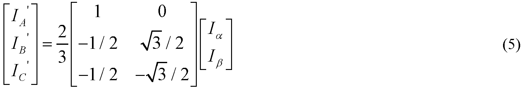
- Wherein, IA ' , IB ' , and IC ' are the three-phase current obtained by transforming, since Iα and Iβ are the compensated two-phase current, the three-phase current IA ', IB ' , and IC ' obtained in this step are the compensated three-phase current, that is the real-time three-phase current.
-
Step 206, for each bridge arm, calculating a product of a current corresponding to the bridge arm from the real-time three-phase current and the pulse width modulation duty cycle corresponding to the bridge arm. - In the embodiment of the present application, the three-phase current value calculated in
step 205 is divided to obtain the current IA ' , IB ' , and IC ' corresponding to each bridge arm of the three-way bridge arms, and the current IA ', IB ' , and IC ' corresponding to each bridge arm are multiplied to the pulse width modulation duty cycles dA, dB, and dC collected instep 201 of the corresponding bridge arm, to obtain dA ∗ IA ', dB ∗ IB ', and dC ∗ IC '. -
Step 207, calculating a sum of the products corresponding to the three-way bridge arms, to obtain the bus current estimated value. - In the embodiment of the present application, the three products in
step 206 are added to obtain the bus current estimated value, that is:
-
Step 208, low-pass filtering the bus current estimated value, to obtain a target bus current value. - In the embodiment of the present application, the low-pass filter is a signal filtering method, and the rule is that low-frequency signals can pass normally, while high-frequency signals exceeding a set threshold are blocked and weakened. However, the magnitude of the blocking and the weakening will vary according to different frequencies and different filtering purposes. Since the estimated bus current value has many high-frequency points, from the waveform, there are many burrs, while the normal bus current is relatively stable and smooth, so after low-pass filtering the estimated bus current, the obtained target bus current value has a better fit with the actual bus current value.
-
Step 209, controlling the permanent magnet synchronous motor according to the target bus current value. - In the embodiment of the present application, the bus current may monitor the controller driven by the permanent magnet synchronous motor, to realize the control of the permanent magnet synchronous motor. The higher the accuracy of the estimated bus current, the better the control performance.
- In conclusion, in the control method provided by the embodiments of the present application, by collecting the rotor position, motor speed, quadrature-axis current, direct-axis current and the pulse width modulation duty cycles of the three-way bridge arms of the permanent magnet synchronous motor, compensating the rotor position according to the motor speed, and then calculating a three-phase current according to the compensated rotor position information, finally, determining a bus current estimated value by using the three-phase current and the PWM value as a calculation input of the bus current, after low-pass filtering the bus current, to obtain a target bus current value, therefore, controlling the permanent magnet synchronous motor according to the target bus current value. The above method can compensate the three-phase current at any position, in all working conditions, no matter whether the motor speed is high or low, there is a high estimation accuracy, which allows engineers to grasp the bus current at any time, and then realize the precise control of the permanent magnet synchronous motor.
- In addition, the embodiment of the present application selects a plurality of test motor speeds within the speed range of the motor, calculates the bus current actual value and bus current estimated value corresponding to each test motor speed, and determines the preset rotor position compensation table according to the difference value between the bus current actual value and bus current estimated value, and the rotor position may be compensated through the preset rotor position compensation table to obtain the real-time rotor position, then the quadrature-axis current and the direct-axis current are transformed into the three-phase current according to the real-time rotor position, therefore, the compensation for the three-phase current is realized, and then the bus current value with higher accuracy may be estimated according to the compensated three-phase current. The above method is simple and easy to implement, and only needs to calibrate the angle of compensation according to the rotation speed, which is convenient for calibration and saves time.
-
FIG. 5 illustrates a first structural block diagram of a controller according to an embodiment of the present application. The controller includes: - a
collection module 501, configured to collect a rotor position, a motor speed, a quadrature-axis current, a direct-axis current and pulse width modulation duty cycles of three-way bridge arms of the permanent magnet synchronous motor; - a real-time rotor
position acquisition module 502, configured to compensate the rotor position by using the motor speed, to obtain a real-time rotor position; - a real-time three-phase
current transformation module 503, configured to transform the quadrature-axis current and the direct-axis current into a real-time three-phase current according to the real-time rotor position; - a bus
current estimating module 504 configured to, according to the real-time three-phase current and the pulse width modulation duty cycles of the three-way bridge arms, determine a bus current estimated value; - a low-
pass filter module 505, configured to low-pass filter the bus current estimated value, to obtain a target bus current value; and - a
control module 506, configured to control the permanent magnet synchronous motor according to the target bus current value. - In the controller provided by the embodiments of the present application, by collecting the rotor position, motor speed, quadrature-axis current, direct-axis current and the pulse width modulation duty cycles of the three-way bridge arms of the permanent magnet synchronous motor, compensating the rotor position according to the motor speed, and then calculating a three-phase current according to the compensated rotor position information, finally, determining a bus current estimated value by using the three-phase current and the PWM value as a calculation input of the bus current, after low-pass filtering the bus current, to obtain a target bus current value, therefore, controlling the permanent magnet synchronous motor according to the target bus current value. The above method can compensate the three-phase current at any position, in all working conditions, no matter whether the motor speed is high or low, there is a high estimation accuracy, which allows engineers to grasp the bus current at any time, and then realize the precise control of the permanent magnet synchronous motor.
- Based on
FIG. 5 ,FIG. 6 illustrates a second structural block diagram of a controller according to an embodiment of the present application. Thecontroller 600 includes: - a
collection module 601, configured to collect a rotor position, a motor speed, a quadrature-axis current, a direct-axis current and pulse width modulation duty cycles of three-way bridge arms of the permanent magnet synchronous motor; - a real-time rotor
position acquisition module 602, configured to compensate the rotor position by using the motor speed, to obtain a real-time rotor position; - a real-time three-phase
current transformation module 603, configured to transform the quadrature-axis current and the direct-axis current into a real-time three-phase current according to the real-time rotor position; - a bus
current estimating module 604 configured to, according to the real-time three-phase current and the pulse width modulation duty cycles of the three-way bridge arms, determine a bus current estimated value; - a low-
pass filter module 605, configured to low-pass filter the bus current estimated value, to obtain a target bus current value; and - a
control module 606, configured to control the permanent magnet synchronous motor according to the target bus current value. - Further, the rotor position is a rotor rotation angle, and the real-time rotor
position acquisition module 602 includes: - a
querying submodule 6021, configured to query a rotor-rotation-angle compensation value corresponding to the motor speed from a preset rotor-position-information compensation table by using the motor speed; wherein the preset rotor-position-information compensation table records a corresponding relation between the motor speed and the rotor-rotation-angle compensation value; and - a compensating
submodule 6022 configured to, according to the rotor-rotation-angle compensation value, compensate the rotor position, to obtain the real-time rotor position. - Further, the
controller 600 further includes: - a
speed selection module 607, configured to select a plurality of test motor speeds in the speed range of the permanent magnet synchronous motor; - a bus
current determination module 608 configured to, for each of the plurality of test motor speeds, determining a bus current actual value and a bus current test value corresponding to the test motor speed; - a compensation
value determination module 609, configured to determine a corresponding rotor-rotation-angle compensation value according to the bus current actual value and the bus current test value corresponding to the test motor speed; and - an adding
module 610, configured to add the rotor-rotation-angle compensation value and the test motor speed into the rotor-position-information compensation table according to the corresponding relation. - Further, the compensation
value determination module 609 includes: - a difference value calculation submodule, configured to calculate a difference value between the bus current actual value and the bus current test value corresponding to each of the plurality of test motor speeds; and
- a compensation value determination submodule, configured to determine the rotor-rotation-angle compensation value corresponding to each of the plurality of test motor speeds according to the difference value.
- Further, the real-time three-phase
current transformation module 603 includes: - a first transformation submodule 6031, configured to transform the quadrature-axis current and the direct-axis current into a two-phase current that is stationary relative to a stator according to the real-time rotor position; and
- a
second transformation submodule 6032, configured to transform the two-phase current that is stationary relative to the stator into the real-time three-phase current. - Further, the bus
current estimating module 604 includes: - a
product calculation submodule 6041 configured to, for each bridge arm, calculate a product of a current corresponding to the bridge arm from the real-time three-phase current and the pulse width modulation duty cycle corresponding to the bridge arm; and - a bus
current estimating submodule 6042, configured to calculate a sum of the products corresponding to the three-way bridge arms, to obtain the bus current estimated value. - In conclusion, in the controller provided by the embodiments of the present application, by collecting the rotor position, motor speed, quadrature-axis current, direct-axis current and the pulse width modulation duty cycles of the three-way bridge arms of the permanent magnet synchronous motor, compensating the rotor position according to the motor speed, and then calculating a three-phase current according to the compensated rotor position information, finally, determining a bus current estimated value by using the three-phase current and the PWM value as a calculation input of the bus current, after low-pass filtering the bus current, to obtain a target bus current value, therefore, controlling the permanent magnet synchronous motor according to the target bus current value. The above method can compensate the three-phase current at any position, in all working conditions, no matter whether the motor speed is high or low, there is a high estimation accuracy, which allows engineers to grasp the bus current at any time, and then realize the precise control of the permanent magnet synchronous motor.
- In addition, the controller of the embodiment of the present application selects a plurality of test motor speeds within the speed range of the motor, calculates the bus current actual value and bus current estimated value corresponding to each test motor speed, and determines the preset rotor position compensation table according to the difference value between the bus current actual value and bus current estimated value, and the rotor position may be compensated through the preset rotor position compensation table to obtain the real-time rotor position, then the quadrature-axis current and the direct-axis current are transformed into the three-phase current according to the real-time rotor position, therefore, the compensation for the three-phase current is realized, and then the bus current value with higher accuracy may be estimated according to the compensated three-phase current. The above method is simple and easy to implement, and only needs to calibrate the angle of compensation according to the rotation speed, which is convenient for calibration and saves time.
- The above descriptions are only preferred embodiments of the present application, and are not intended to limit the present application. Any modification, equivalent replacement, improvement, etc. made within the spirit and principle of the present application shall be included in the scope of protection of the present application.
- The described apparatus embodiment is merely an example, the units described as separate components may or may not be physically separated, and the components displayed as units may or may not be physical units, that is, may be located in one place, or may be distributed to a plurality of network units. Some or all of the modules may be selected according to actual needs to achieve the objectives of the solutions of the embodiment. It can be understood and implemented by those of ordinary skill in the art without creative efforts.
- Component embodiments in the present application may be implemented in hardware, or a software module running on one or more processors, or any combination thereof. It should be understood by those skilled in the art that a microprocessor or digital signal processor (DSP) may be used in practice to achieve some or all of functions of some or all of components in the computing and processing device according to an embodiment of the present application. The present application may also be implemented as a device or apparatus program (e.g., a computer program and a computer program product) for performing some or all of the methods described herein. Such a program for implementing the present application may be stored in a computer-readable medium, or may take the form of one or more signals. Such a signal can be downloaded from an Internet site, or provided on a carrier signal, or in any other form.
- For example,
FIG. 7 shows a computing and processing device capable of implementing the method according to the present application. The computing and processing device conventionally includes aprocessor 1010 and a computer program product or computer-readable medium in the form of amemory 1020. Thememory 1020 may be an electronic memory such as flash memory, EEPROM (electrically erasable programmable read-only memory), EPROM, hard disk or ROM. Thememory 1020 has astorage space 1030 forprogram codes 1031 for executing any one of the method steps in the above method. For example, thestorage space 1030 for program codes may include theprogram codes 1031 for implementing various steps in the above method respectively. These program codes may be read from or written into one or more computer program products. These computer program products include program code carriers such as hard disk, compact disk (CD), memory card or floppy disk. Such a computer program product is typically a portable or fixed storage unit as described with reference toFIG. 8 . The storage unit may have a storage segment or storage space arranged in a manner similar to thememory 1020 of the computing and processing device shown inFIG. 7 . The program codes may, for example, be compressed in an appropriate form. The storage unit typically includes computer-readable codes 1031', i.e., codes that can be read by a processor such as 1010, these codes, when run by the computing and processing device, cause the computing and processing device to perform various steps in the method described above. - As used herein, reference to "one embodiment", "an embodiment" or "one or more embodiments" means that a particular feature, structure, or characteristic described in connection with the embodiment is included in at least one embodiment of the present application. Further, it should be noted that instances of the phrase "in one embodiment" herein do not necessarily refer to the same embodiment.
- Numerous specific details are set forth in the specification provided herein. However, it can be understood that embodiments of the present application may be practiced without these specific details. In some instances, well-known methods, structures and techniques have not been shown in detail in order not to obscure the understanding of the specification.
- In the claims, any reference signs placed between parentheses shall not be construed as limiting to the claim. The word "comprising" does not exclude the presence of elements or steps other than those listed in a claim. The word "a" or "an" preceding an element does not exclude the presence of a plurality of such elements. The present application can be implemented by means of hardware including several different elements and by means of a suitably programmed computer. In a unit claim enumerating several means, several of these means may be embodied by the same item of hardware. The use of the words "first", "second" and "third" does not indicate any sequence. These words can be interpreted as names.
- Finally, it should be noted that the foregoing embodiments are merely intended for describing the technical solutions of the present application rather than limiting the present application. Although the present application is described in detail with reference to the foregoing embodiments, those of ordinary skill in the art should understand that they may still make modifications to the technical solutions described in the foregoing embodiments or make equivalent replacements to some or all technical features thereof, without departing from the scope of the technical solutions of the embodiments of the present application.
Claims (14)
- A control method, wherein the method is applied in a controller of a permanent magnet synchronous motor, and the method comprises:collecting a rotor position, a motor speed, a quadrature-axis current, a direct-axis current and pulse width modulation duty cycles of three-way bridge arms of the permanent magnet synchronous motor;compensating the rotor position by using the motor speed, to obtain a real-time rotor position;transforming the quadrature-axis current and the direct-axis current into a real-time three-phase current according to the real-time rotor position;according to the real-time three-phase current and the pulse width modulation duty cycles of the three-way bridge arms, determining a bus current estimated value;low-pass filtering the bus current estimated value, to obtain a target bus current value; andcontrolling the permanent magnet synchronous motor according to the target bus current value.
- The method according to claim 1, wherein the rotor position is a rotor rotation angle, and compensating the rotor position by using the motor speed, to obtain a real-time rotor position, comprises:querying a rotor-rotation-angle compensation value corresponding to the motor speed from a preset rotor-position-information compensation table by using the motor speed; wherein the preset rotor-position-information compensation table records a corresponding relation between the motor speed and the rotor-rotation-angle compensation value; andaccording to the rotor-rotation-angle compensation value, compensating the rotor position, to obtain the real-time rotor position.
- The method according to claim 2, wherein the preset rotor-position-information compensation table is obtained by the following steps:selecting a plurality of test motor speeds in the speed range of the permanent magnet synchronous motor;for each of the plurality of test motor speeds, determining a bus current actual value and a bus current test value corresponding to the test motor speed;determining a corresponding rotor-rotation-angle compensation value according to the bus current actual value and the bus current test value corresponding to the test motor speed; andadding the rotor-rotation-angle compensation value and the test motor speed into the rotor-position-information compensation table according to the corresponding relation.
- The method according to claim 3, wherein determining a corresponding rotor-rotation-angle compensation value according to the bus current actual value and the bus current test value corresponding to the test motor speed comprises:calculating a difference value between the bus current actual value and the bus current test value corresponding to each of the plurality of test motor speeds; anddetermining the rotor-rotation-angle compensation value corresponding to each of the plurality of test motor speeds according to the difference value.
- The method according to claim 1, wherein transforming the quadrature-axis current and the direct-axis current into a real-time three-phase current according to the real-time rotor position comprises:transforming the quadrature-axis current and the direct-axis current into a two-phase current that is stationary relative to a stator according to the real-time rotor position; andtransforming the two-phase current that is stationary relative to the stator into the real-time three-phase current.
- The method according to claim 1, wherein according to the real-time three-phase current and the pulse width modulation duty cycles of the three-way bridge arms, determining a bus current estimated value, comprises:for each bridge arm, calculating a product of a current corresponding to the bridge arm from the real-time three-phase current and the pulse width modulation duty cycle corresponding to the bridge arm; andcalculating a sum of the products corresponding to the three-way bridge arms, to obtain the bus current estimated value.
- A controller, wherein the controller comprises:a collection module, configured to collect a rotor position, a motor speed, a quadrature-axis current, a direct-axis current and pulse width modulation duty cycles of three-way bridge arms of the permanent magnet synchronous motor;a real-time rotor position acquisition module, configured to compensate the rotor position by using the motor speed, to obtain a real-time rotor position;a real-time three-phase current transformation module, configured to transform the quadrature-axis current and the direct-axis current into a real-time three-phase current according to the real-time rotor position;a bus current estimating module configured to, according to the real-time three-phase current and the pulse width modulation duty cycles of the three-way bridge arms, determine a bus current estimated value;a low-pass filter module, configured to low-pass filter the bus current estimated value, to obtain a target bus current value; anda control module, configured to control the permanent magnet synchronous motor according to the target bus current value.
- The controller according to claim 7, wherein the rotor position is a rotor rotation angle, and the real-time rotor position acquisition module comprises:a querying submodule, configured to query a rotor-rotation-angle compensation value corresponding to the motor speed from a preset rotor-position-information compensation table by using the motor speed; wherein the preset rotor-position-information compensation table records a corresponding relation between the motor speed and the rotor-rotation-angle compensation value; anda compensating submodule configured to, according to the rotor-rotation-angle compensation value, compensate the rotor position, to obtain the real-time rotor position.
- The controller according to claim 8, wherein the controller further comprises:a speed selection module, configured to select a plurality of test motor speeds in the speed range of the permanent magnet synchronous motor;a bus current determination module configured to, for each of the plurality of test motor speeds, determining a bus current actual value and a bus current test value corresponding to the test motor speed;a compensation value determination module, configured to determine a corresponding rotor-rotation-angle compensation value according to the bus current actual value and the bus current test value corresponding to the test motor speed; andan adding module, configured to add the rotor-rotation-angle compensation value and the test motor speed into the rotor-position-information compensation table according to the corresponding relation.
- The controller according to claim 9, wherein the compensation value determination module comprises:a difference value calculation submodule, configured to calculate a difference value between the bus current actual value and the bus current test value corresponding to each of the plurality of test motor speeds; anda compensation value determination submodule, configured to determine the rotor-rotation-angle compensation value corresponding to each of the plurality of test motor speeds according to the difference value.
- The controller according to claim 7, wherein the real-time three-phase current transformation module comprises:a first transformation submodule, configured to transform the quadrature-axis current and the direct-axis current into a two-phase current that is stationary relative to a stator according to the real-time rotor position; anda second transformation submodule, configured to transform the two-phase current that is stationary relative to the stator into the real-time three-phase current.
- The controller according to claim 7, wherein the bus current estimating module comprises:a product calculation submodule configured to, for each bridge arm, calculate a product of a current corresponding to the bridge arm from the real-time three-phase current and the pulse width modulation duty cycle corresponding to the bridge arm; anda bus current estimating submodule, configured to calculate a sum of the products corresponding to the three-way bridge arms, to obtain the bus current estimated value.
- A computer program, comprising a computer readable code, wherein the computer readable code, when running on a computing and processing device, causes the computing and processing device to implement the control method according to any one of claims 1 to 6.
- A computer-readable storage medium, storing the computer program according to claim 13.
Applications Claiming Priority (2)
| Application Number | Priority Date | Filing Date | Title |
|---|---|---|---|
| CN201910818960.1A CN111614288B (en) | 2019-08-30 | 2019-08-30 | Control method and controller |
| PCT/CN2020/108812 WO2021036794A1 (en) | 2019-08-30 | 2020-08-13 | Control method and controller |
Publications (3)
| Publication Number | Publication Date |
|---|---|
| EP4007158A1 true EP4007158A1 (en) | 2022-06-01 |
| EP4007158A4 EP4007158A4 (en) | 2022-09-28 |
| EP4007158B1 EP4007158B1 (en) | 2025-12-24 |
Family
ID=72203121
Family Applications (1)
| Application Number | Title | Priority Date | Filing Date |
|---|---|---|---|
| EP20858002.7A Active EP4007158B1 (en) | 2019-08-30 | 2020-08-13 | Control method and controller |
Country Status (3)
| Country | Link |
|---|---|
| EP (1) | EP4007158B1 (en) |
| CN (1) | CN111614288B (en) |
| WO (1) | WO2021036794A1 (en) |
Families Citing this family (8)
| Publication number | Priority date | Publication date | Assignee | Title |
|---|---|---|---|---|
| CN113037158B (en) * | 2021-03-01 | 2023-04-18 | 潍柴动力股份有限公司 | AC-DC shaft decoupling control method and device for permanent magnet synchronous motor electric driving system |
| CN113193801B (en) * | 2021-04-20 | 2022-04-01 | 华中科技大学 | High-speed motor simulator control system and high-speed motor simulator |
| JP7574443B2 (en) * | 2021-07-01 | 2024-10-28 | 日立Astemo株式会社 | Inverter control device, calculation method |
| CN113872479B (en) * | 2021-09-24 | 2024-08-02 | 东风商用车有限公司 | Permanent magnet synchronous motor controller with bus current estimation function and driving equipment |
| CN114039524B (en) * | 2021-10-25 | 2025-07-04 | 智新科技股份有限公司 | A method for controlling output torque of permanent magnet synchronous motor based on bus current reconstruction |
| CN117984803B (en) * | 2022-10-31 | 2024-08-06 | 比亚迪股份有限公司 | Energy conversion device and vehicle |
| CN115800852B (en) * | 2022-12-09 | 2026-01-20 | 宁波圣龙汽车动力系统股份有限公司 | Zero position calibration method of permanent magnet synchronous motor magnetic encoder |
| CN115967314B (en) * | 2023-01-09 | 2026-02-10 | 深圳市兆威机电股份有限公司 | A phase current compensation method, device, permanent magnet synchronous motor, and storage medium |
Family Cites Families (12)
| Publication number | Priority date | Publication date | Assignee | Title |
|---|---|---|---|---|
| JP3755582B2 (en) * | 2001-02-08 | 2006-03-15 | 三菱電機株式会社 | Electric motor control device |
| US7068001B2 (en) * | 2004-07-29 | 2006-06-27 | Japan Servo Co., Ltd. | Motor control system |
| US8106618B2 (en) * | 2009-04-02 | 2012-01-31 | Daimler Ag | Method and device for calibrating a position sensor placed on a shaft of a permanent magnet synchronous motor |
| CN101924510A (en) * | 2010-07-06 | 2010-12-22 | 奇瑞汽车股份有限公司 | Compensation method for rotor position angle of permanent-magnet motor |
| CN102593841B (en) * | 2011-12-31 | 2014-12-31 | 泰州师范高等专科学校 | Current separation compensation-based cascaded H-bridge distribution static synchronous compensator (DSTATCOM) device and separation compensation method |
| CN102811013B (en) * | 2012-07-31 | 2014-12-17 | 株洲南车时代电气股份有限公司 | AC (alternating current) drive control system and method as well as voltage error measuring method of inverter of AC drive control system |
| EP3040690B1 (en) * | 2013-08-26 | 2021-03-03 | Mitsubishi Electric Corporation | Angle error correction device and angle error correction method for position detector |
| US20160294314A1 (en) * | 2015-03-31 | 2016-10-06 | Texas Instruments Incorporated | Fractional Delay Adjustment in a Field-Oriented Control Architecture |
| CN106788048A (en) * | 2017-03-23 | 2017-05-31 | 南京航空航天大学 | Brushless DC motor control system and control method based on no electrolytic capacitor inverter |
| CN106788072B (en) * | 2017-03-27 | 2019-04-16 | 安徽江淮汽车集团股份有限公司 | Permanent-magnetic synchronous motor rotor initial angle modification method and update the system |
| CN107919828B (en) * | 2017-11-30 | 2019-08-30 | 华中科技大学 | A control device and method for a permanent magnet synchronous motor |
| CN109039199B (en) * | 2018-08-06 | 2020-06-12 | 新乡艾迪威汽车科技有限公司 | Bus current estimation method and system for EPS controller |
-
2019
- 2019-08-30 CN CN201910818960.1A patent/CN111614288B/en active Active
-
2020
- 2020-08-13 WO PCT/CN2020/108812 patent/WO2021036794A1/en not_active Ceased
- 2020-08-13 EP EP20858002.7A patent/EP4007158B1/en active Active
Also Published As
| Publication number | Publication date |
|---|---|
| EP4007158A4 (en) | 2022-09-28 |
| CN111614288B (en) | 2021-12-10 |
| EP4007158B1 (en) | 2025-12-24 |
| CN111614288A (en) | 2020-09-01 |
| WO2021036794A1 (en) | 2021-03-04 |
Similar Documents
| Publication | Publication Date | Title |
|---|---|---|
| EP4007158A1 (en) | Control method and controller | |
| CN101917158B (en) | Dead-zone compensation method for voltage source inverter | |
| EP2258043B1 (en) | Sensorless control of salient-pole machines | |
| CN101174811A (en) | Electric motor control method and device adopting space vector pulse width modulation | |
| CN101867343A (en) | Permanent magnet synchronous motor (PMSM) AC servo system | |
| JP3687603B2 (en) | PM motor magnetic pole position estimation method | |
| US20030184170A1 (en) | Method and apparatus for measuring torque and flux current in a synchronous motor | |
| CN105305915A (en) | Position estimation device, motor drive control device, and position estimation method | |
| EP2605399A1 (en) | Motor drive system and control method thereof | |
| CN108183651A (en) | A kind of control method of permanent magnet linear synchronous motor position-sensor-free | |
| CN106374789A (en) | Hall Fault Tolerant Control Method for Low Torque Ripple of Permanent Magnet Brushless DC Motor | |
| JP6116538B2 (en) | Motor control device | |
| CN103843246A (en) | Motor drive device | |
| CN114567222A (en) | Static initial position estimation method and stator inductance identification method for permanent magnet synchronous motor | |
| JP6953763B2 (en) | Motor control device | |
| CN113644856B (en) | Driving control method of high-frequency converter | |
| Tsotoulidis et al. | A sensorless commutation technique of a brushless DC motor drive system using two terminal voltages in respect to a virtual neutral potential | |
| CN103647482A (en) | Brushless DC (direct current) motor 180-degree square wave control method and module and converter | |
| JPH09121558A (en) | Motor drive control device | |
| EP3370336B1 (en) | Brushless dc motor control and method | |
| JP5806633B2 (en) | Motor control device | |
| EP3133732A1 (en) | Power conversion device and power conversion method | |
| CN113965128A (en) | Permanent magnet motor integrated driving and detecting system and method | |
| CN101080867B (en) | Motor driving device | |
| JP4127000B2 (en) | Motor control device |
Legal Events
| Date | Code | Title | Description |
|---|---|---|---|
| STAA | Information on the status of an ep patent application or granted ep patent |
Free format text: STATUS: THE INTERNATIONAL PUBLICATION HAS BEEN MADE |
|
| PUAI | Public reference made under article 153(3) epc to a published international application that has entered the european phase |
Free format text: ORIGINAL CODE: 0009012 |
|
| STAA | Information on the status of an ep patent application or granted ep patent |
Free format text: STATUS: REQUEST FOR EXAMINATION WAS MADE |
|
| 17P | Request for examination filed |
Effective date: 20220225 |
|
| AK | Designated contracting states |
Kind code of ref document: A1 Designated state(s): AL AT BE BG CH CY CZ DE DK EE ES FI FR GB GR HR HU IE IS IT LI LT LU LV MC MK MT NL NO PL PT RO RS SE SI SK SM TR |
|
| REG | Reference to a national code |
Ref country code: DE Ipc: H02P0021180000 Ref country code: DE Ref legal event code: R079 Ref document number: 602020064530 Country of ref document: DE Free format text: PREVIOUS MAIN CLASS: H02P0006280000 Ipc: H02P0021180000 |
|
| A4 | Supplementary search report drawn up and despatched |
Effective date: 20220829 |
|
| RIC1 | Information provided on ipc code assigned before grant |
Ipc: H02P 27/12 20060101ALI20220823BHEP Ipc: H02P 21/22 20160101ALI20220823BHEP Ipc: H02P 21/00 20160101ALI20220823BHEP Ipc: H02P 21/18 20160101AFI20220823BHEP |
|
| DAV | Request for validation of the european patent (deleted) | ||
| DAX | Request for extension of the european patent (deleted) | ||
| STAA | Information on the status of an ep patent application or granted ep patent |
Free format text: STATUS: EXAMINATION IS IN PROGRESS |
|
| 17Q | First examination report despatched |
Effective date: 20240628 |
|
| GRAP | Despatch of communication of intention to grant a patent |
Free format text: ORIGINAL CODE: EPIDOSNIGR1 |
|
| STAA | Information on the status of an ep patent application or granted ep patent |
Free format text: STATUS: GRANT OF PATENT IS INTENDED |
|
| INTG | Intention to grant announced |
Effective date: 20250730 |
|
| P01 | Opt-out of the competence of the unified patent court (upc) registered |
Free format text: CASE NUMBER: UPC_APP_7528_4007158/2025 Effective date: 20250918 |
|
| GRAS | Grant fee paid |
Free format text: ORIGINAL CODE: EPIDOSNIGR3 |
|
| GRAA | (expected) grant |
Free format text: ORIGINAL CODE: 0009210 |
|
| STAA | Information on the status of an ep patent application or granted ep patent |
Free format text: STATUS: THE PATENT HAS BEEN GRANTED |
|
| AK | Designated contracting states |
Kind code of ref document: B1 Designated state(s): AL AT BE BG CH CY CZ DE DK EE ES FI FR GB GR HR HU IE IS IT LI LT LU LV MC MK MT NL NO PL PT RO RS SE SI SK SM TR |
|
| REG | Reference to a national code |
Ref country code: CH Ref legal event code: F10 Free format text: ST27 STATUS EVENT CODE: U-0-0-F10-F00 (AS PROVIDED BY THE NATIONAL OFFICE) Effective date: 20251224 Ref country code: GB Ref legal event code: FG4D |
|
| REG | Reference to a national code |
Ref country code: DE Ref legal event code: R096 Ref document number: 602020064530 Country of ref document: DE |