EP4006937B1 - Elektrischer schalter - Google Patents
Elektrischer schalter Download PDFInfo
- Publication number
- EP4006937B1 EP4006937B1 EP21177952.5A EP21177952A EP4006937B1 EP 4006937 B1 EP4006937 B1 EP 4006937B1 EP 21177952 A EP21177952 A EP 21177952A EP 4006937 B1 EP4006937 B1 EP 4006937B1
- Authority
- EP
- European Patent Office
- Prior art keywords
- actuator
- movable contact
- lock member
- lock
- snap
- Prior art date
- Legal status (The legal status is an assumption and is not a legal conclusion. Google has not performed a legal analysis and makes no representation as to the accuracy of the status listed.)
- Active
Links
Images


Classifications
-
- H—ELECTRICITY
- H01—ELECTRIC ELEMENTS
- H01H—ELECTRIC SWITCHES; RELAYS; SELECTORS; EMERGENCY PROTECTIVE DEVICES
- H01H13/00—Switches having rectilinearly-movable operating part or parts adapted for pushing or pulling in one direction only, e.g. push-button switch
- H01H13/02—Details
- H01H13/12—Movable parts; Contacts mounted thereon
- H01H13/14—Operating parts, e.g. push-button
- H01H13/18—Operating parts, e.g. push-button adapted for actuation at a limit or other predetermined position in the path of a body, the relative movement of switch and body being primarily for a purpose other than the actuation of the switch, e.g. door switch, limit switch, floor-levelling switch of a lift
- H01H13/186—Operating parts, e.g. push-button adapted for actuation at a limit or other predetermined position in the path of a body, the relative movement of switch and body being primarily for a purpose other than the actuation of the switch, e.g. door switch, limit switch, floor-levelling switch of a lift wherein the pushbutton is rectilinearly actuated by a lever pivoting on the housing of the switch
-
- H—ELECTRICITY
- H01—ELECTRIC ELEMENTS
- H01H—ELECTRIC SWITCHES; RELAYS; SELECTORS; EMERGENCY PROTECTIVE DEVICES
- H01H13/00—Switches having rectilinearly-movable operating part or parts adapted for pushing or pulling in one direction only, e.g. push-button switch
- H01H13/02—Details
- H01H13/26—Snap-action arrangements depending upon deformation of elastic members
- H01H13/28—Snap-action arrangements depending upon deformation of elastic members using compression or extension of coil springs
-
- H—ELECTRICITY
- H01—ELECTRIC ELEMENTS
- H01H—ELECTRIC SWITCHES; RELAYS; SELECTORS; EMERGENCY PROTECTIVE DEVICES
- H01H15/00—Switches having rectilinearly-movable operating part or parts adapted for actuation in opposite directions, e.g. slide switch
- H01H15/005—Switches having rectilinearly-movable operating part or parts adapted for actuation in opposite directions, e.g. slide switch adapted for connection with printed circuit boards
-
- H—ELECTRICITY
- H01—ELECTRIC ELEMENTS
- H01H—ELECTRIC SWITCHES; RELAYS; SELECTORS; EMERGENCY PROTECTIVE DEVICES
- H01H15/00—Switches having rectilinearly-movable operating part or parts adapted for actuation in opposite directions, e.g. slide switch
- H01H15/02—Details
- H01H15/06—Movable parts; Contacts mounted thereon
- H01H15/16—Driving mechanisms
- H01H15/18—Driving mechanisms acting with snap action
-
- H—ELECTRICITY
- H01—ELECTRIC ELEMENTS
- H01H—ELECTRIC SWITCHES; RELAYS; SELECTORS; EMERGENCY PROTECTIVE DEVICES
- H01H23/00—Tumbler or rocker switches, i.e. switches characterised by being operated by rocking an operating member in the form of a rocker button
- H01H23/02—Details
- H01H23/04—Cases; Covers
-
- H—ELECTRICITY
- H01—ELECTRIC ELEMENTS
- H01H—ELECTRIC SWITCHES; RELAYS; SELECTORS; EMERGENCY PROTECTIVE DEVICES
- H01H23/00—Tumbler or rocker switches, i.e. switches characterised by being operated by rocking an operating member in the form of a rocker button
- H01H23/02—Details
- H01H23/12—Movable parts; Contacts mounted thereon
- H01H23/16—Driving mechanisms
- H01H23/20—Driving mechanisms having snap action
-
- H—ELECTRICITY
- H01—ELECTRIC ELEMENTS
- H01H—ELECTRIC SWITCHES; RELAYS; SELECTORS; EMERGENCY PROTECTIVE DEVICES
- H01H5/00—Snap-action arrangements, i.e. in which during a single opening operation or a single closing operation energy is first stored and then released to produce or assist the contact movement
- H01H5/04—Energy stored by deformation of elastic members
- H01H5/045—Energy stored by deformation of elastic members making use of cooperating spring loaded wedging or camming parts between operating member and contact structure
-
- H—ELECTRICITY
- H01—ELECTRIC ELEMENTS
- H01H—ELECTRIC SWITCHES; RELAYS; SELECTORS; EMERGENCY PROTECTIVE DEVICES
- H01H5/00—Snap-action arrangements, i.e. in which during a single opening operation or a single closing operation energy is first stored and then released to produce or assist the contact movement
- H01H5/04—Energy stored by deformation of elastic members
- H01H5/06—Energy stored by deformation of elastic members by compression or extension of coil springs
- H01H5/08—Energy stored by deformation of elastic members by compression or extension of coil springs one end of spring transmitting movement to the contact member when the other end is moved by the operating part
-
- H—ELECTRICITY
- H01—ELECTRIC ELEMENTS
- H01H—ELECTRIC SWITCHES; RELAYS; SELECTORS; EMERGENCY PROTECTIVE DEVICES
- H01H9/00—Details of switching devices, not covered by groups H01H1/00 - H01H7/00
- H01H9/20—Interlocking, locking, or latching mechanisms
-
- H—ELECTRICITY
- H01—ELECTRIC ELEMENTS
- H01H—ELECTRIC SWITCHES; RELAYS; SELECTORS; EMERGENCY PROTECTIVE DEVICES
- H01H13/00—Switches having rectilinearly-movable operating part or parts adapted for pushing or pulling in one direction only, e.g. push-button switch
- H01H13/50—Switches having rectilinearly-movable operating part or parts adapted for pushing or pulling in one direction only, e.g. push-button switch having a single operating member
- H01H13/52—Switches having rectilinearly-movable operating part or parts adapted for pushing or pulling in one direction only, e.g. push-button switch having a single operating member the contact returning to its original state immediately upon removal of operating force, e.g. bell-push switch
-
- H—ELECTRICITY
- H01—ELECTRIC ELEMENTS
- H01H—ELECTRIC SWITCHES; RELAYS; SELECTORS; EMERGENCY PROTECTIVE DEVICES
- H01H23/00—Tumbler or rocker switches, i.e. switches characterised by being operated by rocking an operating member in the form of a rocker button
- H01H23/02—Details
- H01H23/12—Movable parts; Contacts mounted thereon
- H01H23/16—Driving mechanisms
- H01H23/164—Driving mechanisms with rectilinearly movable member carrying the contacts
Definitions
- This application relates to switches for electrical appliances, in particular to an electric switch.
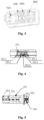
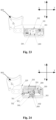
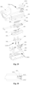
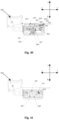
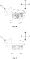
- this embodiment provides an electric switch, including a casing 100 and a mounting cavity 1000 provided in the casing 100.
- the mounting cavity 1000 is provided with an actuator 200, a movable contact frame 300, a snap-action resilient member 400, a lock mechanism 1100, a contact switch 800 and a signal switch 700.
- the lock mechanism 1100 includes a first lock member 500 and a second lock member 600.
- the snap-action resilient member 400 includes a first spring 401 and a second spring 402 arranged on two sides of the drive portion 201.
- the first spring 401 may be compressed by one side of the drive portion 201 to store energy
- the second spring 402 may be compressed by the other side of the drive portion 201 to store energy.
- the first spring 401 when the drive portion 201 moves in the positive direction of the first direction, the first spring 401 can be compressed by the drive portion 201 to store energy; and when the drive portion 201 moves in the negative direction of the first direction, the second spring 402 is compressed by the drive portion to store energy.
- the snap-action resilient member 400 may also adopt a single spring structure.
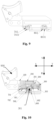
- the retaining portion 302 is a convex block extending downward from a bottom surface of the movable contact frame 300. In some embodiments, there are two retaining portions 302 which are oppositely arranged on two sides of the strip-shaped hole 3015.
- the movement of the movable contact frame 300 can drive the movable contact 801 to move close to or away from the fixed contact 802, so that the movable contact 801 and the fixed contact 802 are in contact with or separated from each other, thereby controlling the on/off of the circuit.
- the button 900 is pressed, and the actuator 200 is driven to move in the positive direction of the first direction.
- the drive portion 201 of the actuator 200 is located on the second abutment surface 3012 and the fourth abutment surface 3014 of the movable contact frame 300, and the first spring 401 and the second spring 402 are located in the movable contact frame 300. At this time, the drive portion 201 of the actuator 200 does not compress the first spring 401 and the second spring 402 for energy storage.
- the actuator 200 when the button 900 is continuously pressed, the actuator 200 is driven to move in the positive direction of the first direction.
- the drive portion 201 of the actuator 200 contacts and interacts with the first spring 401 in the movable contact frame 300, and the movable contact frame 300 is driven to move in the positive direction of the first direction.
- the retaining portion 302 of the movable contact frame 300 abuts on the lock portion a of the first lock member 500.
- the first lock member 500 locks the movable contact frame 300, and the movable contact frame 300 is not able to move.
- the drive portion 201 of the actuator 200 is located between the second abutment surface 3012 and the fourth abutment surface 3014 of the movable contact frame 300.
- the first spring 401 and the second spring 402 are located in the movable contact frame 300.
- the drive portion 201 of the actuator 200 does not exert a compression force on the first spring 401 and the second spring 402 for energy storage.
- the protrusion 7051 can abut against the inner side walls of the second groove 205, and the protrusion 7051 is driven to slide in the sliding hole 1011 with the movement of the actuator 200.
- the brush 701 is driven to slide by the brush holder 705.
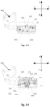
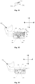
- the electric switch is in the initial state, and the first lock member 500 does not play a locking role.
- the unlock portion b of the first lock member 500 abuts on the top of the mounting cavity 1000, and the unlock portion b of the second lock member 600 abuts on the plane of the abutting portion 202 of the actuator 200.
- the first spring 401 is located in the movable contact frame 300, and two ends of the first spring 401 abut on the first abutment surface 3011 and the second abutment surface 3012, respectively.
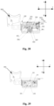
- the actuator 200 when the button 900 is pressed, the actuator 200 is driven to move in the positive direction of the first direction.
- the drive portion 201 of the actuator 200 is located between the second abutment surface 3012 and the fourth abutment surface 3014 of the movable contact frame 300, and the first spring 401 and the second spring 402 are located in the movable contact frame 300.
- the drive portion 201 of the actuator 200 does not compress the first spring 401 and the second spring 402.
- the unlock portion b of the first lock member 500 still abuts on the top of the mounting cavity 1000, and the abutting portion 202 of the actuator 200 starts to move away from the second lock member 600 and approach the first lock member 500.
- the movable contact frame 300 is still in the initial state and has not moved.
- the protrusion 7051 is displaced in the second groove 205, and the position of the protrusion 7051 changes, but it still does not contact the right inner side wall of the second groove 205.
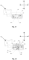
- the actuator 200 when the button 900 is continuously pressed, the actuator 200 is driven to move in the positive direction of the first direction.
- the drive portion 201 of the actuator 200 contacts and interacts with the first spring 401 in the movable contact frame 300, the movable contact frame 300 is driven to move in the positive direction of the first direction.
- the retaining portion 302 of the movable contact frame 300 abuts on the lock portion a of the first lock member 500.
- the first lock member 500 locks the movable contact frame 300, and the movable contact frame 300 is not capable of moving.
- the drive portion 201 of the actuator 200 is located between the second abutment surface 3012 and the fourth abutment surface 3014 of the movable contact frame 300.
- the first spring 401 and the second spring 402 are located in the movable contact frame 300.
- the drive portion 201 of the actuator 200 does not compress the first spring 401 and the second spring 402.
- the protrusion 7051 is displaced in the second groove 205, and the position of the protrusion 7051 changes, but it still does not contact the right inner side wall of the second groove 205.
- the actuator 200 is driven to move in the positive direction of the first direction. Since the movable contact frame 300 is locked by the first lock member 500, the movable contact frame 300 does not move.
- the first spring 401 in the movable contact frame 300 is compressed by the drive portion 201 for energy storage.
- the unlock portion b of the first lock member 500 is pressed by the front slope of the abutting portion 202 of the actuator 200 and moves in the positive direction of the second direction until the critical state of unlocking is reached.
- the protrusion 7051 is displaced in the actuation groove 205, the position of the protrusion 7051 changes, and the protrusion 7051 just contacts the right inner side wall of the second groove 205.
- the actuator 200 continues to move in the positive direction of the first direction.
- the protrusion 7051 is in contact with the right side wall of the second groove 205, and the protrusion 7051 is driven to move under the movement of the actuator 200, thereby driving the brush 701 to slide on the circuit board 702 and contact the conductive sheet on the circuit board 702 to switch on the signal switch 700.
- the unlock portion b of the first lock member 500 is pressed by the abutting portion 202 of the actuator 200, and the first lock member 500 moves in the positive direction of the second direction to unlock the movable contact frame 300.
- the first spring 401 immediately produces a snap action to release energy, and the movable contact frame 300 moves rapidly in the positive direction of the first direction.
- the movable contact 801 contacts the fixed contact 802, causing the contact switch 800 to be switched on instantaneously.
- the second lock member 600 moves in the negative direction of the second direction under the action of the reset portion c to lock the movable contact frame 300.
- the actuator 200 continues to move in the positive direction of the first direction, and the first spring 401 is compressed by the drive portion 201 of the actuator 200 to store energy.
- the first lock member 500 is in an unlocked state, and the second lock member 600 still locks the movable contact frame 300, and the contact switch 800 and the signal switch 700 are still in an on state.
- the button 900 is released, and the actuator 200 moves in the negative direction of the first direction under the action of the elastic force of the reset element 203 and the first spring 401.
- the drive portion 201 is located between the second abutment surface 3012 and the fourth abutment surface 3014 of the movable contact frame 300, and the second spring 402 is not compressed for the energy storage by the drive portion 201.
- the rear slope of the abutting portion 202 abuts on the first slope s1 of the second lock member 600, and the second lock member 600 still locks the movable contact frame 300.
- the contact switch 800 and the signal switch 700 are still in the on state.
- the actuator 200 continues to move in the negative direction of the first direction. Since the second lock member 600 locks the movable contact frame 300, the drive part 201 compresses the second spring 402 for energy storage. The unlock portion b of the second lock member 600 is pressed by the rear slope of the abutting portion 202 of the actuator 200 and moves in the positive direction of the second direction until the critical state of unlocking is reached.
- the protrusion 7051 is displaced in the second groove 205, and the position of the protrusion 7051 changes, and the protrusion 7051 contacts the left inner side wall of the second groove 205.
- the actuator 200 drives the brush 701 to reset, and the signal switch 700 is switched off instantaneously.
- the second lock member 600 is unlocked, and the second spring 402 suddenly releases energy to drive the movable contact frame 300 to move rapidly in the negative direction of the first direction, so that the contact switch 800 is switched off instantaneously.
- the lock portion a of the first lock member 500 moves upward under the action of the reset portion c and abuts the retaining portion 302 of the movable contact frame 300 for locking the movable contact frame 300 until the button returns to the initial position. At this time, the electric switch returns to the initial state.
- some structures of the electric switch can adopt existing structures, which will not be described in detail herein.
- first and second are only used for descriptive purposes, and cannot be understood as indicating or implying relative importance or implicitly indicating the number of indicated technical features. Thus, the features defined with “first” and “second” may explicitly or implicitly include one or more of these features. In the description of the present invention, unless specified, the term “plurality” means two or more.
- first and second features may contact each other in a direct manner or through another feature located therebetween.
- terms “on”, “above” and “over” indicate that the second feature is directly above or obliquely above the second feature, or simply mean that the level of the first feature is higher than that of the second feature.
- Terms “under”, “below” and “beneath” indicate that the second feature is directly below or obliquely below the second feature, or simply mean that the level of the first feature is lower than that of the second feature.
Landscapes
- Push-Button Switches (AREA)
Claims (9)
- Elektrischer Schalter, umfassend ein Gehäuse (100), einen im Gehäuse (100) vorgesehenen Montagehohlraum (1000) und einen Aktuator (200), einen beweglichen Kontaktrahmen (300), ein elastisches Schnappglied (400), einen Verriegelungsmechanismus (1100), einen Kontaktschalter (800) und einen Signalschalter (700), die im Montagehohlraum (1000) vorgesehen sind;dadurch gekennzeichnet, dass der Aktuator (200) in der Lage ist, sich in dem Montagehohlraum (1000) entlang einer ersten Richtung hin und her zu bewegen;wobei der bewegliche Kontaktrahmen (300) mit einem Rückhalteabschnitt (302) versehen ist;wobei das elastische Schnappglied (400) in dem beweglichen Kontaktrahmen (300) angeordnet ist und so konfiguriert ist, dass es durch den Aktuator (200) bei einer Bewegung des Aktuators (200) zusammengedrückt wird;wobei der Verriegelungsmechanismus (1100) ein erstes Verriegelungselement (500) und ein zweites Verriegelungselement (600) umfasst; wobei das erste Verriegelungselement (500) und das zweite Verriegelungselement (600) so konfiguriert sind, dass sie sich in dem Montagehohlraum (1000) mit der Bewegung des Aktuators (200) in einer zweiten Richtung hin- und herbewegen, um den Rückhalteabschnitt (302) zu verriegeln oder zu entriegeln;wobei der Signalschalter (700) eine Bürste (701) und eine Leiterplatte (702) umfasst, wobei die Bürste (701) auf dem beweglichen Kontaktrahmen (300) angeordnet ist und die Leiterplatte (702) in dem Montagehohlraum (1000) angeordnet ist;wobei der Kontaktschalter (800) einen beweglichen Kontakt (801) und einen festen Kontakt (802) umfasst; wobei der bewegliche Kontakt (801) auf dem beweglichen Kontaktrahmen (300) angeordnet ist und der feste Kontakt (802) in dem Montagehohlraum (1000) angeordnet ist;wenn der Aktuator (200) angetrieben wird, um sich entlang der ersten Richtung zu bewegen, das erste Verriegelungselement (500) den Rückhalteabschnitt (302) verriegelt und das zweite Verriegelungselement (600) den Rückhalteabschnitt (302) nicht verriegelt und das elastische Schnappglied (400) durch den Aktuator (200) zur Energiespeicherung zusammengedrückt wird; wenn den Aktuator (200) angetrieben wird, um sich kontinuierlich entlang der ersten Richtung zu bewegen, das erste Verriegelungselement (500) den Rückhalteabschnitt (302) entriegelt und das elastische Schnappglied (400) eine Schnappwirkung erzeugt, um Energie freizusetzen, um den beweglichen Kontaktrahmen (300) anzutreiben, sich zu bewegen, so dass die Bürste (701) angetrieben wird, um auf der Leiterplatte (702) zu gleiten, um den Signalschalter (700) ein-/auszuschalten; gleichzeitig wird der bewegliche Kontakt (801) angetrieben, um sich nahe an den festen Kontakt (802) heranzubewegen oder sich von diesem wegzubewegen, so dass der bewegliche Kontakt (801) in Kontakt mit dem festen Kontakt (802) steht oder von diesem getrennt ist, wodurch der Kontaktschalter (800) ein-/ausgeschaltet werden kann; während der Bewegung des beweglichen Kontaktrahmens (300) das zweite Verriegelungselement (600) den Rückhalteabschnitt (302) verriegelt;wobei der Aktuator (200) einen Antriebsabschnitt (201) und einen mit dem Antriebsabschnitt (201) verbundenen Anschlagabschnitt (202) umfasst; wobei der Anschlagabschnitt (202) in der Lage ist, sich mit dem Antriebsabschnitt (201) zu bewegen; wobei der Antriebsabschnitt (201) in den beweglichen Kontaktrahmen (300) eingesetzt ist und sich mit dem Aktuator (200) bewegt; wobei der Antriebsabschnitt (201) in der Lage ist, das elastische Schnappglied (400) zusammenzudrücken, um es dem elastischen Schnappglied (400) zu ermöglichen, Energie zu speichern; und wobei der Anschlagabschnitt (202) in der Lage ist, gegen das erste Verriegelungselement (500) oder das zweite Verriegelungselement (600) zu stoßen, um das erste Verriegelungselement (500) oder das zweite Verriegelungselement (600) anzutreiben, um den Rückhalteabschnitt (302) zu entriegeln;wobei das erste Verriegelungselement (500) und das zweite Verriegelungselement (600) jeweils einen Verriegelungsabschnitt (a), einen Entriegelungsabschnitt (b) und einen Rückstellabschnitt (c) umfassen; wobei ein Ende des Rückstellabschnitts (c) in dem Montagehohlraum (1000) anliegt, wobei der Rückstellabschnitt (c) zusammengedrückt werden kann, wenn er einer durch den Aktuator (200) in der zweiten Richtung ausgeübten Druckkraft ausgesetzt wird; wenn die Druckkraft entfernt wird, der Rückstellabschnitt (c) eine Rückstellkraft aufweist, die in der zweiten Richtung entgegengesetzt zur Druckkraft ist; wobei die Rückstellkraft es dem Verriegelungsabschnitt (a) ermöglicht, sich entlang der zweiten Richtung zu bewegen und den Rückhalteabschnitt (302) zu verriegeln, um die Bewegung des beweglichen Kontaktrahmens (300) zu begrenzen; wobei der Entriegelungsabschnitt (b) durch den Aktuator (200) gedrückt wird, um die Rückstellkraft des Rückstellabschnitts (c) zu überwinden, damit der Verriegelungsabschnitt (a) von dem Rückhalteabschnitt (302) gelöst werden kann
- Elektrischer Schalter nach Anspruch 1, dadurch gekennzeichnet, dass das elastische Schnappglied (400) eine erste Feder (401) und eine zweite Feder (402) umfasst, die jeweils an zwei Seiten des Antriebsabschnitts (201) angeordnet sind; wobei die erste Feder (401) von einer Seite des Antriebsabschnitts (201) zur Energiespeicherung zusammengedrückt werden kann und die zweite Feder (402) von der anderen Seite des Antriebsabschnitts (201) zur Energiespeicherung zusammengedrückt werden kann.
- Elektrischer Schalter nach Anspruch 1, dadurch gekennzeichnet, dass er ferner umfasst:ein erstes Teminal (703); undein zweites Teminal (803);wobei die Leiterplatte (702) durch das erste Teminal (703) im Montagehohlraum (1000) montiert wird und der feste Kontakt (802) durch das weite Teminal (803) im Montagehohlraum (1000) montiert wird.
- Elektrischer Schalter nach Anspruch 3, dadurch gekennzeichnet, dass die Leiterplatte (702) über ein erstes elastisches Element (704) elektrisch mit dem ersten Teminal (703) verbunden ist; oder die Leiterplatte (702) und das erste Teminal (703) vernietet sind.
- Elektrischer Schalter nach Anspruch 3, dadurch gekennzeichnet, dass das erste Teminal (703) mit einer ersten Senkbohrung (7031) versehen ist und in der ersten Senkbohrung (7031) das erste Teminal (703) über eine erste Sicherungsschraube mit einem Außenleiter verbunden ist; dass das zweite Teminal (803) mit einer zweiten Senkbohrung (8031) versehen ist und in der zweiten Senkbohrung (8031) d zasweite Teminal (803) über eine zweite Sicherungsschraube mit dem Außenleiter verbunden ist.
- Elektrischer Schalter nach Anspruch 1, dadurch gekennzeichnet, dass ein erster Montageschlitz (304) und ein zweiter Montageschlitz (305) jeweils auf zwei Seiten des Rückhalteabschnitts (302) des beweglichen Kontaktrahmens (300) angeordnet sind; wobei die Bürste (701) im ersten Montageschlitz (304) angeordnet ist und der bewegliche Kontakt (801) im zweiten Montageschlitz (305) angeordnet ist.
- Elektrischer Schalter, umfassend ein Gehäuse (100), einen im Gehäuse (100) vorgesehenen Montagehohlraum (1000) und einen Aktuator (200), einen beweglichen Kontaktrahmen (300), ein elastisches Schnappglied (400), einen Verriegelungsmechanismus (1100), einen Kontaktschalter (800) und einen Signalschalter (700), die im Montagehohlraum (1000) vorgesehen sind;dadurch gekennzeichnet, dass der Aktuator (200) in der Lage ist, sich in dem Montagehohlraum (1000) entlang einer ersten Richtung hin und her zu bewegen;wobei der bewegliche Kontaktrahmen (300) mit einem Rückhalteabschnitt (302) versehen ist;wobei das elastische Schnappglied (400) in dem beweglichen Kontaktrahmen (300) angeordnet ist und so konfiguriert ist, dass es durch den Aktuator (200) bei einer Bewegung des Aktuators (200) zusammengedrückt wird;wobei der Verriegelungsmechanismus (1100) ein erstes Verriegelungselement (500) und ein zweites Verriegelungselement (600) umfasst; wobei das erste Verriegelungselement (500) und das zweite Verriegelungselement (600) so konfiguriert sind, dass sie sich in dem Montagehohlraum (1000) mit der Bewegung des Aktuators (200) in einer zweiten Richtung hin- und herbewegen, um den Rückhalteabschnitt (302) zu verriegeln oder zu entriegeln;wobei der Signalschalter (700) eine Bürste (701) und eine Leiterplatte (702) umfasst; die Bürste (701) mit dem Aktuator (200) verbunden ist, so dass der Aktuator (200) die Bürste (701) zur Bewegung antreibt; und die Leiterplatte (702) am Gehäuse (100) angeordnet ist;wobei der Kontaktschalter (800) einen beweglichen Kontakt (801) und einen festen Kontakt (802) umfasst; wobei der bewegliche Kontakt (801) auf dem beweglichen Kontaktrahmen (300) angeordnet ist und der feste Kontakt (802) in dem Montagehohlraum (1000) angeordnet ist;wenn der Aktuator (200) angetrieben wird, um sich entlang der ersten Richtung zu bewegen, das erste Verriegelungselement (500) den Rückhalteabschnitt (302) verriegelt und das zweite Verriegelungselement (600) den Rückhalteabschnitt (302) nicht verriegelt und das elastische Schnappglied (400) durch den Aktuator (200) zur Energiespeicherung zusammengedrückt wird; wenn den Aktuator (200) angetrieben wird, um sich kontinuierlich entlang der ersten Richtung zu bewegen, das erste Verriegelungselement (500) den Rückhalteabschnitt (302) entriegelt und das elastische Schnappglied (400) eine Schnappwirkung erzeugt, um Energie freizusetzen, um den beweglichen Kontaktrahmen (300) anzutreiben, sich zu bewegen, so dass die Bürste (701) angetrieben wird, um auf der Leiterplatte (702) zu gleiten, um den Signalschalter (700) ein-/auszuschalten; gleichzeitig wird der bewegliche Kontakt (801) angetrieben, um sich nahe an den festen Kontakt (802) heranzubewegen oder sich von diesem wegzubewegen, so dass der bewegliche Kontakt (801) in Kontakt mit dem festen Kontakt (802) steht oder von diesem getrennt ist, wodurch der Kontaktschalter (800) ein-/ausgeschaltet werden kann; während der Bewegung des beweglichen Kontaktrahmens (300) das zweite Verriegelungselement (600) den Rückhalteabschnitt (302) verriegelt; wobei der Aktuator (200) einen Antriebsabschnitt (201) und einen mit dem Antriebsabschnitt (201) verbundenen Anschlagabschnitt (202) umfasst; wobei der Anschlagabschnitt (202) in der Lage ist, sich mit dem Antriebsabschnitt (201) zu bewegen; wobei der Antriebsabschnitt (201) in den beweglichen Kontaktrahmen (300) eingesetzt ist und sich mit dem Aktuator (200) bewegt; wobei der Antriebsabschnitt (201) in der Lage ist, das elastische Schnappglied (400) zusammenzudrücken, um es dem elastischen Schnappglied (400) zu ermöglichen, Energie zu speichern; und wobei der Anschlagabschnitt (202) in der Lage ist, gegen den ersten Verriegelungsabschnitt (500) oder den zweitem Verriegelungsabschnitt (600) zu stoßen, um den ersten Verriegelungsabschnitt (500) oder den zweiten Verriegelungsabschnitt (600) anzutreiben, um den Rückhalteabschnitt (302) zu entriegeln;wobei das erste Verriegelungselement (500) und das zweite Verriegelungselement (600) jeweils einen Verriegelungsabschnitt (a), einen Entriegelungsabschnitt (b) und einen Rückstellabschnitt (c) umfassen; wobei ein Ende des Rückstellabschnitts (c) in dem Montagehohlraum (1000) anliegt, wobei der Rückstellabschnitt (c) zusammengedrückt werden kann, wenn er einer durch den Aktuator (200) in der zweiten Richtung ausgeübten Druckkraft ausgesetzt wird; wenn die Druckkraft entfernt wird, der Rückstellabschnitt (c) eine Rückstellkraft aufweist, die in der zweiten Richtung entgegengesetzt zur Druckkraft ist; wobei die Rückstellkraft es dem Verriegelungsabschnitt (a) ermöglicht, sich entlang der zweiten Richtung zu bewegen und den Rückhalteabschnitt (302) zu verriegeln, um die Bewegung des beweglichen Kontaktrahmens (300) zu begrenzen; wobei der Entriegelungsabschnitt (b) durch den Aktuator (200) gedrückt wird, um die Rückstellkraft des Rückstellabschnitts (c) zu überwinden, damit der Verriegelungsabschnitt (a) von dem Rückhalteabschnitt (302) gelöst werden kann.
- Elektrischer Schalter nach Anspruch 7, dadurch gekennzeichnet, dass das Gehäuse (100) mit einer ersten Nut (101) versehen ist, und ein Bürstenhalter (705) in der ersten Nut (101) vorgesehen ist; und die Bürste (701) auf dem Bürstenhalter (705) angeordnet ist, und der Aktuator (200) mit einer zweiten Nut (205) versehen ist; der Bürstenhalter (705) in die zweite Nut (205) eingesetzt wird, so dass der Bürstenhalter (705) angetrieben wird, sich in der ersten Nut (101) durch eine innere Seitenwand der zweiten Nut (205) zu bewegen.
- Elektrischer Schalter nach Anspruch 8, dadurch gekennzeichnet, dass in der ersten Nut (101) eine Aufhängung (1012) vorgesehen ist und die Leiterplatte (702) durch die Aufhängung (1012) am Gehäuse (100) angeordnet und durch ein Harz (1014) versiegelt ist.
Applications Claiming Priority (1)
| Application Number | Priority Date | Filing Date | Title |
|---|---|---|---|
| CN202011359250.6A CN112466697A (zh) | 2020-11-27 | 2020-11-27 | 一种电开关 |
Publications (3)
| Publication Number | Publication Date |
|---|---|
| EP4006937A1 EP4006937A1 (de) | 2022-06-01 |
| EP4006937B1 true EP4006937B1 (de) | 2024-07-10 |
| EP4006937C0 EP4006937C0 (de) | 2024-07-10 |
Family
ID=74809118
Family Applications (1)
| Application Number | Title | Priority Date | Filing Date |
|---|---|---|---|
| EP21177952.5A Active EP4006937B1 (de) | 2020-11-27 | 2021-06-07 | Elektrischer schalter |
Country Status (3)
| Country | Link |
|---|---|
| US (1) | US11456126B2 (de) |
| EP (1) | EP4006937B1 (de) |
| CN (1) | CN112466697A (de) |
Families Citing this family (1)
| Publication number | Priority date | Publication date | Assignee | Title |
|---|---|---|---|---|
| USD963599S1 (en) * | 2020-06-30 | 2022-09-13 | Paccar Inc | Switch cap |
Family Cites Families (24)
| Publication number | Priority date | Publication date | Assignee | Title |
|---|---|---|---|---|
| US4006333A (en) * | 1975-06-11 | 1977-02-01 | Cutler-Hammer, Inc. | Higher rated double-pole trigger switch |
| US4121069A (en) * | 1976-08-19 | 1978-10-17 | Cutler-Hammer, Inc. | Snap-action electric switch with fulcrum means for limited contact sliding and positive-off torque |
| US4149053A (en) * | 1976-10-26 | 1979-04-10 | Cutler-Hammer, Inc. | Safety disconnect electric switch |
| DE19930558A1 (de) * | 1998-07-24 | 2000-01-27 | Marquardt Gmbh | Elektrischer Schalter |
| JP2002075157A (ja) * | 2000-08-28 | 2002-03-15 | Matsushita Electric Works Ltd | 回路遮断器 |
| JP4063528B2 (ja) * | 2001-11-27 | 2008-03-19 | 佐鳥エス・テック株式会社 | スイッチの接触機構 |
| DK1939906T3 (da) * | 2006-12-28 | 2010-05-03 | Defond Components Ltd | Elektrisk afbryder |
| CN201256096Y (zh) * | 2008-09-23 | 2009-06-10 | 郑春开 | 一种按键突跳开关 |
| CN101740267B (zh) * | 2008-11-13 | 2012-11-21 | 科都电气有限公司 | 一种带有锁定机构的电磁开关 |
| CN102290269B (zh) * | 2011-07-27 | 2013-09-18 | 科都电气有限公司 | 一种带触点开关 |
| US8604376B2 (en) * | 2012-02-10 | 2013-12-10 | Defond Components Limited | Electrical switch |
| CN102723219B (zh) * | 2012-06-20 | 2014-09-24 | 科都电气有限公司 | 一种具有锁定机构的突跳开关 |
| CN202871660U (zh) * | 2012-11-15 | 2013-04-10 | 科都电气有限公司 | 一种具有突跳机构的扳动开关 |
| CN103050308B (zh) * | 2012-12-11 | 2014-10-01 | 科都电气有限公司 | 一种具有突跳功能的调速开关 |
| CN103280358B (zh) * | 2013-06-04 | 2015-09-09 | 科都电气有限公司 | 直流调速开关 |
| CN203325769U (zh) * | 2013-06-04 | 2013-12-04 | 科都电气有限公司 | 直流调速开关 |
| CN104091716B (zh) * | 2014-07-24 | 2016-09-07 | 科都电气有限公司 | 一种突跳旋转开关 |
| EP3166123B1 (de) | 2015-11-09 | 2018-05-02 | Microprécision Electronics Holding SA | Elektrischer schalter |
| CN106252964B (zh) * | 2016-08-31 | 2018-08-14 | 黄金和 | 具有反接线保护功能的漏电保护插座 |
| JP6932074B2 (ja) | 2017-12-13 | 2021-09-08 | 株式会社ヴァレオジャパン | スイッチ |
| CN109935487B (zh) * | 2019-05-05 | 2024-03-19 | 科都电气股份有限公司 | 一种按动开关 |
| CN211125437U (zh) | 2019-12-31 | 2020-07-28 | 科都电气有限公司 | 一种按动开关 |
| CN211529833U (zh) * | 2020-01-21 | 2020-09-18 | 科都电气有限公司 | 一种按钮开关 |
| CN214123763U (zh) * | 2020-11-27 | 2021-09-03 | 科都电气股份有限公司 | 一种电开关 |
-
2020
- 2020-11-27 CN CN202011359250.6A patent/CN112466697A/zh active Pending
-
2021
- 2021-06-07 EP EP21177952.5A patent/EP4006937B1/de active Active
- 2021-06-18 US US17/352,228 patent/US11456126B2/en active Active
Also Published As
| Publication number | Publication date |
|---|---|
| CN112466697A (zh) | 2021-03-09 |
| EP4006937A1 (de) | 2022-06-01 |
| EP4006937C0 (de) | 2024-07-10 |
| US20210313124A1 (en) | 2021-10-07 |
| US11456126B2 (en) | 2022-09-27 |
Similar Documents
| Publication | Publication Date | Title |
|---|---|---|
| CN110265272B (zh) | 一种小型断路器操作机构及小型断路器 | |
| US7997352B2 (en) | Electric power tool | |
| CN113078036B (zh) | 一种微型断路器的操作脱扣系统 | |
| CN113161211A (zh) | 一种断路器装置 | |
| EP4006937B1 (de) | Elektrischer schalter | |
| US4061895A (en) | Higher rated double-pole trigger switch | |
| CN108520841A (zh) | 一种磁吸式微动开关 | |
| CN214898306U (zh) | 一种断路器装置 | |
| US6005201A (en) | Switch | |
| CN214123763U (zh) | 一种电开关 | |
| JP2001155585A (ja) | 直流電流用スイッチ | |
| CN214123764U (zh) | 一种电开关 | |
| CN211957499U (zh) | 一种按压开关 | |
| CN112466696B (zh) | 一种电开关 | |
| CN211670146U (zh) | 一种集成电子开关的触头装置 | |
| CN214411022U (zh) | 一种电开关 | |
| CN210743842U (zh) | 一种带突跳功能的按动开关 | |
| CN212209392U (zh) | 一种脱扣机构及断路器 | |
| JP3718576B2 (ja) | プッシュスイッチ | |
| CN220065494U (zh) | 一种锁定状态的微动开关 | |
| CN223181002U (zh) | 一种带灯按键开关 | |
| CN220731435U (zh) | 断路器 | |
| CN118748137B (zh) | 一种漏电断路器n极模组 | |
| CN222672846U (zh) | 一种储能快动的断路器 | |
| CN224067638U (zh) | 一种按键式过载保护开关 |
Legal Events
| Date | Code | Title | Description |
|---|---|---|---|
| PUAI | Public reference made under article 153(3) epc to a published international application that has entered the european phase |
Free format text: ORIGINAL CODE: 0009012 |
|
| STAA | Information on the status of an ep patent application or granted ep patent |
Free format text: STATUS: REQUEST FOR EXAMINATION WAS MADE |
|
| 17P | Request for examination filed |
Effective date: 20210607 |
|
| AK | Designated contracting states |
Kind code of ref document: A1 Designated state(s): AL AT BE BG CH CY CZ DE DK EE ES FI FR GB GR HR HU IE IS IT LI LT LU LV MC MK MT NL NO PL PT RO RS SE SI SK SM TR |
|
| STAA | Information on the status of an ep patent application or granted ep patent |
Free format text: STATUS: EXAMINATION IS IN PROGRESS |
|
| 17Q | First examination report despatched |
Effective date: 20231122 |
|
| GRAP | Despatch of communication of intention to grant a patent |
Free format text: ORIGINAL CODE: EPIDOSNIGR1 |
|
| STAA | Information on the status of an ep patent application or granted ep patent |
Free format text: STATUS: GRANT OF PATENT IS INTENDED |
|
| INTG | Intention to grant announced |
Effective date: 20240404 |
|
| GRAS | Grant fee paid |
Free format text: ORIGINAL CODE: EPIDOSNIGR3 |
|
| GRAA | (expected) grant |
Free format text: ORIGINAL CODE: 0009210 |
|
| STAA | Information on the status of an ep patent application or granted ep patent |
Free format text: STATUS: THE PATENT HAS BEEN GRANTED |
|
| AK | Designated contracting states |
Kind code of ref document: B1 Designated state(s): AL AT BE BG CH CY CZ DE DK EE ES FI FR GB GR HR HU IE IS IT LI LT LU LV MC MK MT NL NO PL PT RO RS SE SI SK SM TR |
|
| REG | Reference to a national code |
Ref country code: CH Ref legal event code: EP |
|
| REG | Reference to a national code |
Ref country code: DE Ref legal event code: R096 Ref document number: 602021015364 Country of ref document: DE |
|
| U01 | Request for unitary effect filed |
Effective date: 20240712 |
|
| U07 | Unitary effect registered |
Designated state(s): AT BE BG DE DK EE FI FR IT LT LU LV MT NL PT SE SI Effective date: 20240726 |
|
| PG25 | Lapsed in a contracting state [announced via postgrant information from national office to epo] |
Ref country code: NO Free format text: LAPSE BECAUSE OF FAILURE TO SUBMIT A TRANSLATION OF THE DESCRIPTION OR TO PAY THE FEE WITHIN THE PRESCRIBED TIME-LIMIT Effective date: 20241010 |
|
| PG25 | Lapsed in a contracting state [announced via postgrant information from national office to epo] |
Ref country code: GR Free format text: LAPSE BECAUSE OF FAILURE TO SUBMIT A TRANSLATION OF THE DESCRIPTION OR TO PAY THE FEE WITHIN THE PRESCRIBED TIME-LIMIT Effective date: 20241011 Ref country code: PL Free format text: LAPSE BECAUSE OF FAILURE TO SUBMIT A TRANSLATION OF THE DESCRIPTION OR TO PAY THE FEE WITHIN THE PRESCRIBED TIME-LIMIT Effective date: 20240710 |
|
| PG25 | Lapsed in a contracting state [announced via postgrant information from national office to epo] |
Ref country code: IS Free format text: LAPSE BECAUSE OF FAILURE TO SUBMIT A TRANSLATION OF THE DESCRIPTION OR TO PAY THE FEE WITHIN THE PRESCRIBED TIME-LIMIT Effective date: 20241110 |
|
| PG25 | Lapsed in a contracting state [announced via postgrant information from national office to epo] |
Ref country code: HR Free format text: LAPSE BECAUSE OF FAILURE TO SUBMIT A TRANSLATION OF THE DESCRIPTION OR TO PAY THE FEE WITHIN THE PRESCRIBED TIME-LIMIT Effective date: 20240710 |
|
| PG25 | Lapsed in a contracting state [announced via postgrant information from national office to epo] |
Ref country code: RS Free format text: LAPSE BECAUSE OF FAILURE TO SUBMIT A TRANSLATION OF THE DESCRIPTION OR TO PAY THE FEE WITHIN THE PRESCRIBED TIME-LIMIT Effective date: 20241010 Ref country code: ES Free format text: LAPSE BECAUSE OF FAILURE TO SUBMIT A TRANSLATION OF THE DESCRIPTION OR TO PAY THE FEE WITHIN THE PRESCRIBED TIME-LIMIT Effective date: 20240710 |
|
| PG25 | Lapsed in a contracting state [announced via postgrant information from national office to epo] |
Ref country code: RS Free format text: LAPSE BECAUSE OF FAILURE TO SUBMIT A TRANSLATION OF THE DESCRIPTION OR TO PAY THE FEE WITHIN THE PRESCRIBED TIME-LIMIT Effective date: 20241010 Ref country code: PL Free format text: LAPSE BECAUSE OF FAILURE TO SUBMIT A TRANSLATION OF THE DESCRIPTION OR TO PAY THE FEE WITHIN THE PRESCRIBED TIME-LIMIT Effective date: 20240710 Ref country code: NO Free format text: LAPSE BECAUSE OF FAILURE TO SUBMIT A TRANSLATION OF THE DESCRIPTION OR TO PAY THE FEE WITHIN THE PRESCRIBED TIME-LIMIT Effective date: 20241010 Ref country code: IS Free format text: LAPSE BECAUSE OF FAILURE TO SUBMIT A TRANSLATION OF THE DESCRIPTION OR TO PAY THE FEE WITHIN THE PRESCRIBED TIME-LIMIT Effective date: 20241110 Ref country code: HR Free format text: LAPSE BECAUSE OF FAILURE TO SUBMIT A TRANSLATION OF THE DESCRIPTION OR TO PAY THE FEE WITHIN THE PRESCRIBED TIME-LIMIT Effective date: 20240710 Ref country code: GR Free format text: LAPSE BECAUSE OF FAILURE TO SUBMIT A TRANSLATION OF THE DESCRIPTION OR TO PAY THE FEE WITHIN THE PRESCRIBED TIME-LIMIT Effective date: 20241011 Ref country code: ES Free format text: LAPSE BECAUSE OF FAILURE TO SUBMIT A TRANSLATION OF THE DESCRIPTION OR TO PAY THE FEE WITHIN THE PRESCRIBED TIME-LIMIT Effective date: 20240710 |
|
| PG25 | Lapsed in a contracting state [announced via postgrant information from national office to epo] |
Ref country code: SM Free format text: LAPSE BECAUSE OF FAILURE TO SUBMIT A TRANSLATION OF THE DESCRIPTION OR TO PAY THE FEE WITHIN THE PRESCRIBED TIME-LIMIT Effective date: 20240710 |
|
| PG25 | Lapsed in a contracting state [announced via postgrant information from national office to epo] |
Ref country code: CZ Free format text: LAPSE BECAUSE OF FAILURE TO SUBMIT A TRANSLATION OF THE DESCRIPTION OR TO PAY THE FEE WITHIN THE PRESCRIBED TIME-LIMIT Effective date: 20240710 |
|
| PG25 | Lapsed in a contracting state [announced via postgrant information from national office to epo] |
Ref country code: SK Free format text: LAPSE BECAUSE OF FAILURE TO SUBMIT A TRANSLATION OF THE DESCRIPTION OR TO PAY THE FEE WITHIN THE PRESCRIBED TIME-LIMIT Effective date: 20240710 |
|
| PLBE | No opposition filed within time limit |
Free format text: ORIGINAL CODE: 0009261 |
|
| STAA | Information on the status of an ep patent application or granted ep patent |
Free format text: STATUS: NO OPPOSITION FILED WITHIN TIME LIMIT |
|
| 26N | No opposition filed |
Effective date: 20250411 |
|
| U20 | Renewal fee for the european patent with unitary effect paid |
Year of fee payment: 5 Effective date: 20250515 |
|
| REG | Reference to a national code |
Ref country code: CH Ref legal event code: H13 Free format text: ST27 STATUS EVENT CODE: U-0-0-H10-H13 (AS PROVIDED BY THE NATIONAL OFFICE) Effective date: 20260127 |
|
| PG25 | Lapsed in a contracting state [announced via postgrant information from national office to epo] |
Ref country code: MC Free format text: LAPSE BECAUSE OF FAILURE TO SUBMIT A TRANSLATION OF THE DESCRIPTION OR TO PAY THE FEE WITHIN THE PRESCRIBED TIME-LIMIT Effective date: 20240710 |
|
| GBPC | Gb: european patent ceased through non-payment of renewal fee |
Effective date: 20250607 |