EP4006937B1 - Electric switch - Google Patents
Electric switch Download PDFInfo
- Publication number
- EP4006937B1 EP4006937B1 EP21177952.5A EP21177952A EP4006937B1 EP 4006937 B1 EP4006937 B1 EP 4006937B1 EP 21177952 A EP21177952 A EP 21177952A EP 4006937 B1 EP4006937 B1 EP 4006937B1
- Authority
- EP
- European Patent Office
- Prior art keywords
- actuator
- movable contact
- lock member
- lock
- snap
- Prior art date
- Legal status (The legal status is an assumption and is not a legal conclusion. Google has not performed a legal analysis and makes no representation as to the accuracy of the status listed.)
- Active
Links
Images











Classifications
-
- H—ELECTRICITY
- H01—ELECTRIC ELEMENTS
- H01H—ELECTRIC SWITCHES; RELAYS; SELECTORS; EMERGENCY PROTECTIVE DEVICES
- H01H13/00—Switches having rectilinearly-movable operating part or parts adapted for pushing or pulling in one direction only, e.g. push-button switch
- H01H13/02—Details
- H01H13/12—Movable parts; Contacts mounted thereon
- H01H13/14—Operating parts, e.g. push-button
- H01H13/18—Operating parts, e.g. push-button adapted for actuation at a limit or other predetermined position in the path of a body, the relative movement of switch and body being primarily for a purpose other than the actuation of the switch, e.g. door switch, limit switch, floor-levelling switch of a lift
- H01H13/186—Operating parts, e.g. push-button adapted for actuation at a limit or other predetermined position in the path of a body, the relative movement of switch and body being primarily for a purpose other than the actuation of the switch, e.g. door switch, limit switch, floor-levelling switch of a lift wherein the pushbutton is rectilinearly actuated by a lever pivoting on the housing of the switch
-
- H—ELECTRICITY
- H01—ELECTRIC ELEMENTS
- H01H—ELECTRIC SWITCHES; RELAYS; SELECTORS; EMERGENCY PROTECTIVE DEVICES
- H01H13/00—Switches having rectilinearly-movable operating part or parts adapted for pushing or pulling in one direction only, e.g. push-button switch
- H01H13/02—Details
- H01H13/26—Snap-action arrangements depending upon deformation of elastic members
- H01H13/28—Snap-action arrangements depending upon deformation of elastic members using compression or extension of coil springs
-
- H—ELECTRICITY
- H01—ELECTRIC ELEMENTS
- H01H—ELECTRIC SWITCHES; RELAYS; SELECTORS; EMERGENCY PROTECTIVE DEVICES
- H01H15/00—Switches having rectilinearly-movable operating part or parts adapted for actuation in opposite directions, e.g. slide switch
- H01H15/005—Switches having rectilinearly-movable operating part or parts adapted for actuation in opposite directions, e.g. slide switch adapted for connection with printed circuit boards
-
- H—ELECTRICITY
- H01—ELECTRIC ELEMENTS
- H01H—ELECTRIC SWITCHES; RELAYS; SELECTORS; EMERGENCY PROTECTIVE DEVICES
- H01H15/00—Switches having rectilinearly-movable operating part or parts adapted for actuation in opposite directions, e.g. slide switch
- H01H15/02—Details
- H01H15/06—Movable parts; Contacts mounted thereon
- H01H15/16—Driving mechanisms
- H01H15/18—Driving mechanisms acting with snap action
-
- H—ELECTRICITY
- H01—ELECTRIC ELEMENTS
- H01H—ELECTRIC SWITCHES; RELAYS; SELECTORS; EMERGENCY PROTECTIVE DEVICES
- H01H23/00—Tumbler or rocker switches, i.e. switches characterised by being operated by rocking an operating member in the form of a rocker button
- H01H23/02—Details
- H01H23/04—Cases; Covers
-
- H—ELECTRICITY
- H01—ELECTRIC ELEMENTS
- H01H—ELECTRIC SWITCHES; RELAYS; SELECTORS; EMERGENCY PROTECTIVE DEVICES
- H01H23/00—Tumbler or rocker switches, i.e. switches characterised by being operated by rocking an operating member in the form of a rocker button
- H01H23/02—Details
- H01H23/12—Movable parts; Contacts mounted thereon
- H01H23/16—Driving mechanisms
-
- H—ELECTRICITY
- H01—ELECTRIC ELEMENTS
- H01H—ELECTRIC SWITCHES; RELAYS; SELECTORS; EMERGENCY PROTECTIVE DEVICES
- H01H23/00—Tumbler or rocker switches, i.e. switches characterised by being operated by rocking an operating member in the form of a rocker button
- H01H23/02—Details
- H01H23/12—Movable parts; Contacts mounted thereon
- H01H23/16—Driving mechanisms
- H01H23/20—Driving mechanisms having snap action
-
- H—ELECTRICITY
- H01—ELECTRIC ELEMENTS
- H01H—ELECTRIC SWITCHES; RELAYS; SELECTORS; EMERGENCY PROTECTIVE DEVICES
- H01H5/00—Snap-action arrangements, i.e. in which during a single opening operation or a single closing operation energy is first stored and then released to produce or assist the contact movement
- H01H5/04—Energy stored by deformation of elastic members
- H01H5/045—Energy stored by deformation of elastic members making use of cooperating spring loaded wedging or camming parts between operating member and contact structure
-
- H—ELECTRICITY
- H01—ELECTRIC ELEMENTS
- H01H—ELECTRIC SWITCHES; RELAYS; SELECTORS; EMERGENCY PROTECTIVE DEVICES
- H01H5/00—Snap-action arrangements, i.e. in which during a single opening operation or a single closing operation energy is first stored and then released to produce or assist the contact movement
- H01H5/04—Energy stored by deformation of elastic members
- H01H5/06—Energy stored by deformation of elastic members by compression or extension of coil springs
-
- H—ELECTRICITY
- H01—ELECTRIC ELEMENTS
- H01H—ELECTRIC SWITCHES; RELAYS; SELECTORS; EMERGENCY PROTECTIVE DEVICES
- H01H5/00—Snap-action arrangements, i.e. in which during a single opening operation or a single closing operation energy is first stored and then released to produce or assist the contact movement
- H01H5/04—Energy stored by deformation of elastic members
- H01H5/06—Energy stored by deformation of elastic members by compression or extension of coil springs
- H01H5/08—Energy stored by deformation of elastic members by compression or extension of coil springs one end of spring transmitting movement to the contact member when the other end is moved by the operating part
-
- H—ELECTRICITY
- H01—ELECTRIC ELEMENTS
- H01H—ELECTRIC SWITCHES; RELAYS; SELECTORS; EMERGENCY PROTECTIVE DEVICES
- H01H9/00—Details of switching devices, not covered by groups H01H1/00 - H01H7/00
- H01H9/20—Interlocking, locking, or latching mechanisms
-
- H—ELECTRICITY
- H01—ELECTRIC ELEMENTS
- H01H—ELECTRIC SWITCHES; RELAYS; SELECTORS; EMERGENCY PROTECTIVE DEVICES
- H01H13/00—Switches having rectilinearly-movable operating part or parts adapted for pushing or pulling in one direction only, e.g. push-button switch
- H01H13/50—Switches having rectilinearly-movable operating part or parts adapted for pushing or pulling in one direction only, e.g. push-button switch having a single operating member
- H01H13/52—Switches having rectilinearly-movable operating part or parts adapted for pushing or pulling in one direction only, e.g. push-button switch having a single operating member the contact returning to its original state immediately upon removal of operating force, e.g. bell-push switch
-
- H—ELECTRICITY
- H01—ELECTRIC ELEMENTS
- H01H—ELECTRIC SWITCHES; RELAYS; SELECTORS; EMERGENCY PROTECTIVE DEVICES
- H01H23/00—Tumbler or rocker switches, i.e. switches characterised by being operated by rocking an operating member in the form of a rocker button
- H01H23/02—Details
- H01H23/12—Movable parts; Contacts mounted thereon
- H01H23/16—Driving mechanisms
- H01H23/164—Driving mechanisms with rectilinearly movable member carrying the contacts
Definitions
- This application relates to switches for electrical appliances, in particular to an electric switch.
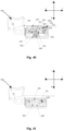
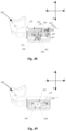
- this embodiment provides an electric switch, including a casing 100 and a mounting cavity 1000 provided in the casing 100.
- the mounting cavity 1000 is provided with an actuator 200, a movable contact frame 300, a snap-action resilient member 400, a lock mechanism 1100, a contact switch 800 and a signal switch 700.
- the lock mechanism 1100 includes a first lock member 500 and a second lock member 600.
- the snap-action resilient member 400 includes a first spring 401 and a second spring 402 arranged on two sides of the drive portion 201.
- the first spring 401 may be compressed by one side of the drive portion 201 to store energy
- the second spring 402 may be compressed by the other side of the drive portion 201 to store energy.
- the first spring 401 when the drive portion 201 moves in the positive direction of the first direction, the first spring 401 can be compressed by the drive portion 201 to store energy; and when the drive portion 201 moves in the negative direction of the first direction, the second spring 402 is compressed by the drive portion to store energy.
- the snap-action resilient member 400 may also adopt a single spring structure.
- the retaining portion 302 is a convex block extending downward from a bottom surface of the movable contact frame 300. In some embodiments, there are two retaining portions 302 which are oppositely arranged on two sides of the strip-shaped hole 3015.
- the movement of the movable contact frame 300 can drive the movable contact 801 to move close to or away from the fixed contact 802, so that the movable contact 801 and the fixed contact 802 are in contact with or separated from each other, thereby controlling the on/off of the circuit.
- the button 900 is pressed, and the actuator 200 is driven to move in the positive direction of the first direction.
- the drive portion 201 of the actuator 200 is located on the second abutment surface 3012 and the fourth abutment surface 3014 of the movable contact frame 300, and the first spring 401 and the second spring 402 are located in the movable contact frame 300. At this time, the drive portion 201 of the actuator 200 does not compress the first spring 401 and the second spring 402 for energy storage.
- the actuator 200 when the button 900 is continuously pressed, the actuator 200 is driven to move in the positive direction of the first direction.
- the drive portion 201 of the actuator 200 contacts and interacts with the first spring 401 in the movable contact frame 300, and the movable contact frame 300 is driven to move in the positive direction of the first direction.
- the retaining portion 302 of the movable contact frame 300 abuts on the lock portion a of the first lock member 500.
- the first lock member 500 locks the movable contact frame 300, and the movable contact frame 300 is not able to move.
- the drive portion 201 of the actuator 200 is located between the second abutment surface 3012 and the fourth abutment surface 3014 of the movable contact frame 300.
- the first spring 401 and the second spring 402 are located in the movable contact frame 300.
- the drive portion 201 of the actuator 200 does not exert a compression force on the first spring 401 and the second spring 402 for energy storage.
- the protrusion 7051 can abut against the inner side walls of the second groove 205, and the protrusion 7051 is driven to slide in the sliding hole 1011 with the movement of the actuator 200.
- the brush 701 is driven to slide by the brush holder 705.
- the electric switch is in the initial state, and the first lock member 500 does not play a locking role.
- the unlock portion b of the first lock member 500 abuts on the top of the mounting cavity 1000, and the unlock portion b of the second lock member 600 abuts on the plane of the abutting portion 202 of the actuator 200.
- the first spring 401 is located in the movable contact frame 300, and two ends of the first spring 401 abut on the first abutment surface 3011 and the second abutment surface 3012, respectively.
- the actuator 200 when the button 900 is pressed, the actuator 200 is driven to move in the positive direction of the first direction.
- the drive portion 201 of the actuator 200 is located between the second abutment surface 3012 and the fourth abutment surface 3014 of the movable contact frame 300, and the first spring 401 and the second spring 402 are located in the movable contact frame 300.
- the drive portion 201 of the actuator 200 does not compress the first spring 401 and the second spring 402.
- the unlock portion b of the first lock member 500 still abuts on the top of the mounting cavity 1000, and the abutting portion 202 of the actuator 200 starts to move away from the second lock member 600 and approach the first lock member 500.
- the movable contact frame 300 is still in the initial state and has not moved.
- the protrusion 7051 is displaced in the second groove 205, and the position of the protrusion 7051 changes, but it still does not contact the right inner side wall of the second groove 205.
- the actuator 200 when the button 900 is continuously pressed, the actuator 200 is driven to move in the positive direction of the first direction.
- the drive portion 201 of the actuator 200 contacts and interacts with the first spring 401 in the movable contact frame 300, the movable contact frame 300 is driven to move in the positive direction of the first direction.
- the retaining portion 302 of the movable contact frame 300 abuts on the lock portion a of the first lock member 500.
- the first lock member 500 locks the movable contact frame 300, and the movable contact frame 300 is not capable of moving.
- the drive portion 201 of the actuator 200 is located between the second abutment surface 3012 and the fourth abutment surface 3014 of the movable contact frame 300.
- the first spring 401 and the second spring 402 are located in the movable contact frame 300.
- the drive portion 201 of the actuator 200 does not compress the first spring 401 and the second spring 402.
- the protrusion 7051 is displaced in the second groove 205, and the position of the protrusion 7051 changes, but it still does not contact the right inner side wall of the second groove 205.
- the actuator 200 is driven to move in the positive direction of the first direction. Since the movable contact frame 300 is locked by the first lock member 500, the movable contact frame 300 does not move.
- the first spring 401 in the movable contact frame 300 is compressed by the drive portion 201 for energy storage.
- the unlock portion b of the first lock member 500 is pressed by the front slope of the abutting portion 202 of the actuator 200 and moves in the positive direction of the second direction until the critical state of unlocking is reached.
- the protrusion 7051 is displaced in the actuation groove 205, the position of the protrusion 7051 changes, and the protrusion 7051 just contacts the right inner side wall of the second groove 205.
- the actuator 200 continues to move in the positive direction of the first direction.
- the protrusion 7051 is in contact with the right side wall of the second groove 205, and the protrusion 7051 is driven to move under the movement of the actuator 200, thereby driving the brush 701 to slide on the circuit board 702 and contact the conductive sheet on the circuit board 702 to switch on the signal switch 700.
- the unlock portion b of the first lock member 500 is pressed by the abutting portion 202 of the actuator 200, and the first lock member 500 moves in the positive direction of the second direction to unlock the movable contact frame 300.
- the first spring 401 immediately produces a snap action to release energy, and the movable contact frame 300 moves rapidly in the positive direction of the first direction.
- the movable contact 801 contacts the fixed contact 802, causing the contact switch 800 to be switched on instantaneously.
- the second lock member 600 moves in the negative direction of the second direction under the action of the reset portion c to lock the movable contact frame 300.
- the actuator 200 continues to move in the positive direction of the first direction, and the first spring 401 is compressed by the drive portion 201 of the actuator 200 to store energy.
- the first lock member 500 is in an unlocked state, and the second lock member 600 still locks the movable contact frame 300, and the contact switch 800 and the signal switch 700 are still in an on state.
- the button 900 is released, and the actuator 200 moves in the negative direction of the first direction under the action of the elastic force of the reset element 203 and the first spring 401.
- the drive portion 201 is located between the second abutment surface 3012 and the fourth abutment surface 3014 of the movable contact frame 300, and the second spring 402 is not compressed for the energy storage by the drive portion 201.
- the rear slope of the abutting portion 202 abuts on the first slope s1 of the second lock member 600, and the second lock member 600 still locks the movable contact frame 300.
- the contact switch 800 and the signal switch 700 are still in the on state.
- the actuator 200 continues to move in the negative direction of the first direction. Since the second lock member 600 locks the movable contact frame 300, the drive part 201 compresses the second spring 402 for energy storage. The unlock portion b of the second lock member 600 is pressed by the rear slope of the abutting portion 202 of the actuator 200 and moves in the positive direction of the second direction until the critical state of unlocking is reached.
- the protrusion 7051 is displaced in the second groove 205, and the position of the protrusion 7051 changes, and the protrusion 7051 contacts the left inner side wall of the second groove 205.
- the actuator 200 drives the brush 701 to reset, and the signal switch 700 is switched off instantaneously.
- the second lock member 600 is unlocked, and the second spring 402 suddenly releases energy to drive the movable contact frame 300 to move rapidly in the negative direction of the first direction, so that the contact switch 800 is switched off instantaneously.
- the lock portion a of the first lock member 500 moves upward under the action of the reset portion c and abuts the retaining portion 302 of the movable contact frame 300 for locking the movable contact frame 300 until the button returns to the initial position. At this time, the electric switch returns to the initial state.
- some structures of the electric switch can adopt existing structures, which will not be described in detail herein.
- first and second are only used for descriptive purposes, and cannot be understood as indicating or implying relative importance or implicitly indicating the number of indicated technical features. Thus, the features defined with “first” and “second” may explicitly or implicitly include one or more of these features. In the description of the present invention, unless specified, the term “plurality” means two or more.
- first and second features may contact each other in a direct manner or through another feature located therebetween.
- terms “on”, “above” and “over” indicate that the second feature is directly above or obliquely above the second feature, or simply mean that the level of the first feature is higher than that of the second feature.
- Terms “under”, “below” and “beneath” indicate that the second feature is directly below or obliquely below the second feature, or simply mean that the level of the first feature is lower than that of the second feature.
Landscapes
- Push-Button Switches (AREA)
Description
- This application relates to switches for electrical appliances, in particular to an electric switch.
- An electric switch is electrically powered and is an important trigger component in mechanical devices. Generally, it is configured to control the start and interruption of electrical devices. The electric switch includes a high-current contact switch and a low-current signal switch.
- In the prior art, a snap-action mechanism is provided at a middle inside the electric switch, and a snap-action spring in the snap-action mechanism suddenly jumps to swing in the longitudinal direction. The snap-action spring of the snap-action mechanism not only provides a transverse action force to drive the action mechanism to operate, but also produces a large longitudinal component force, which is transmitted to a movable contact to generate positive pressure on the movable contact, thus causing the sliding parts of the action mechanism to suffer from severe wear.
- In addition, after the snap-action movement of the spring, the transverse force increases as the swing angle increases, which will cause an increased impact force between contacts, resulting in intensified snap action between the contacts. The arc generated between the contacts may easily burn the contacts. The snap-action spring experiences repeated twist and swing during the working process, which makes the snap-action spring prone to break due to fatigue, shortening the service life of the snap-action spring. Furthermore, the lock mechanism of the electric switch also moves longitudinally, and the pressure acts on the tail of the action mechanism, causing the action mechanism to swing up and down. Thus, a movable contact and a fixed contact rub up and down, which will shorten the service life of the contacts. With respect to the signal switch, the arrangement position is relatively limited, and the brush moves up and down, and has a complicated structure. Moreover, some additional components, such as stop frames, are needed.
-
US patent publication No. 4121069A discloses an electric snap-action switch having a movable contactor with oppositely inclined camming surfaces meeting at an apex on the top thereof. The contactor is centrally biased upwardly from below and cammed downwardly from above by a laterally movable operator traversing the inclined camming surfaces such that the contactor snaps laterally against vertical stationary contacts as the apex is crossed by the operator. The electric snap-action switch includes fulcrum means effective to stop the downward movement of the contactor before the operator crosses the apex whereby a moment arm is formed from a fulcrum to the point of operator-contactor engagement such that further movement of the operator towards the apex effectuates a torque on the contactor to pivot the contactor about the fulcrum to positively break any welds or other frictional attachments between the contacts without relying on the stored energy of the carrier biasing means, thereby affording a switch having little possibility of failure in an "on" position. The inclined camming surfaces of the contactor may be formed with compound slopes to assure constant operator pressure prior to trip point as the contactor pivots and increases the angle of inclination of the camming surface traversed by the operator. - In order to solve the above technical solutions, the present disclosure aims to provide an electric switch which has a prolonged service life and may be arranged in diversified manners to properly utilize the space.
- Technical solutions of the disclosure are described as follows.
- In a first aspect, the present disclosure provides an electric switch, comprising: a casing;
- wherein a mounting cavity is provided in the casing; and an actuator, a movable contact frame, a snap-action resilient member, a lock mechanism, a contact switch and a signal switch are provided in the mounting cavity;
- the actuator is capable of reciprocating in the mounting cavity along a first direction;
- the movable contact frame is provided with a retaining portion;
- the snap-action resilient member is arranged in the movable contact frame, and is configured to be compressed by the actuator with movement of the actuator;
- the lock mechanism comprises a first lock member and a second lock member; and the first lock member and the second lock member are configured to reciprocate in the mounting cavity along with movement of the actuator in a second direction to lock or unlock the retaining portion;
- the signal switch comprises a brush and a circuit board; the brush is arranged on the movable contact frame, and the circuit board is arranged in the mounting cavity;
- the contact switch comprises a movable contact and a fixed contact; the movable contact is arranged on the movable contact frame, and the fixed contact is arranged in the mounting cavity;
- when the actuator is driven to move along the first direction, the first lock member locks the retaining portion, and the second lock member does not lock the retaining portion, and the snap-action resilient member is compressed by the actuator for energy storage; when the actuator is driven to continuously move along the first direction, the first lock member unlocks the retaining portion, and the snap-action resilient member produces a snap action to release energy to drive the movable contact frame to move, so that the brush is driven to slide on the circuit board to switch on/off the signal switch; at the same time, the movable contact is driven to move close to or away from the fixed contact, so that the movable contact is in contact with or separated from the fixed contact, allowing the contact switch to be switched on/off; during the movement of the movable contact frame, the second lock member locks the retaining portion;
- wherein the actuator comprises a drive portion and an abutting portion connected to the drive portion; the abutting portion is capable of moving with the drive portion; the drive portion is inserted into the movable contact frame and moves with the actuator; the drive portion is capable of compressing the snap-action resilient member to allow the snap-action resilient member to store energy; and the abutting portion is capable of abutting against the first lock member or the second lock member to drive the first lock member or the second lock member to unlock the retaining portion;
- each of the first lock member and the second lock member comprises a lock portion, an unlock portion and a reset portion; one end of the reset portion abuts in the mounting cavity, and the reset portion is able to be compressed when subjected to a compression force exerted by the actuator in the second direction; when the compression force is removed, the reset portion has a reset force which is in the second direction and opposite to the compression force; the reset force allows the lock portion to move along the second direction and lock the retaining portion to limit the movement of the movable contact frame; the unlock portion is pressed by the actuator to overcome the reset force of the reset portion to allow the lock portion to be detached from the retaining portion.
- In some embodiments, when the electric switch is in an initial state, the snap-action resilient member does not produce a snap action, and the first lock member and the second lock member do not play a locking role, and the actuator drives the movable contact frame to move in the first direction to allow the movable contact frame to contact the first lock member. At this time, the first lock member locks the movable contact frame. When the actuator continues to move in the first direction, the snap-action resilient member mounted in the movable contact frameis compressed by the actuator. At the same time, the actuator presses the first lock member to unlock the movable contact frame until a critical position of unlocking is reached. After the movable contact frame is unlocked, the snap-action resilient member is released instantaneously, and the movable contact frame moves quickly along the first direction to enable the signal switch and the contact switch to be switched on instantaneously. At this time, the second lock member locks the movable contact frame, which ensuresthe reliable connection of the contact switch, and eliminatesthe contact bounce and the poor contact caused byimproper operation, effectively preventing the contacts from being burned andprolonging the service life of the electric switch.When the actuator is driven to move in the first direction to reset, the snap-action resilient member produces a reverse snap action to enable the electric switch to beswitched off or on instantaneously. The snap-action force generated by the snap-action resilient member is a pure horizontal force, which is different from the diagonal snap-action force generated by the conventional electric switches. The signal switch may be arranged at a front end or a rear end of a bottom of the mounting cavity, so as to properly utilize the space.
- In some embodiments, the snap-action resilient member comprises a first spring and a second spring which are respectively arranged at two sides of the drive portion; the first spring is able to be compressed by one side of the drive portion for energy storage, and the second spring is able to be compressed by the other side of the drive portion for energy storage.
- In some embodiments, the electric switch furthercomprises a first terminal and a second terminal; the circuit board is mounted in the mounting cavity through the first terminal, and the fixed contact is mounted in the mounting cavity through the second terminal.
- In some embodiments, the circuit board is electrically connected to the first terminal through a first resilient element; or the circuit board and the first terminal are riveted.
- In some embodiments, the first terminal is provided with a first counterbore; in the first counterbore, the first terminal is connected to a first external conductor through a first locking screw; the second terminal is provided with a second counterbore; and in the second counterbore, the second terminal is connected to a second external conductor through a second locking screw.
- In some embodiments, a first mounting slot and a second mounting slot are respectively arranged on two sides of the retaining portion of the movable contact frame; the brush is arranged in the first mounting slot, and the movable contact is arranged in the second mounting slot.
- In a second aspect, the present disclosure provides an electric switch, comprising:
- a casing;
- wherein a mounting cavity is provided in the casing; and an actuator, a movable contact frame, a snap-action resilient member, a lock mechanism, a contact switch and a signal switch are provided in the mounting cavity;
- the actuator is capable of reciprocating in the mounting cavity along a first direction;
- the movable contact frame is provided with a retaining portion;
- the snap-action resilient member is arranged in the movable contact frame, and is configured to be compressed by the actuator with movement of the actuator;
- the lock mechanism comprises a first lock member and a second lock member; and the first lock member and the second lock member are configured to reciprocate in the mounting cavity with the movement of the actuator in a second direction to lock or unlock the retaining portion;
- the signal switch comprises a brush and a circuit board; the brush is connected to the actuator, so that the actuator drives the brush to move; and the circuit board is arranged on the casing;
- the contact switch comprises a movable contact and a fixed contact; the movable contact is arranged on the movable contact frame, and the fixed contact is arranged in the mounting cavity;
- when the actuator is driven to move along the first direction, the first lock member locks the retaining portion, and the second lock member does not lock the retaining portion, and the snap-action resilient member is compressed by the actuator for energy storage; when the actuator is driven to continuously move along the first direction, the first lock member unlocks the retaining portion, and the snap-action resilient member produces a snap action to release energy to drive the movable contact frame to move; the movable contact is driven to move close to or away from the fixed contact, so that the movable contact is in contact with or separated from the fixed contact, allowing the contact switch to be switched on/off; the brush is driven by the actuator to move on the circuit board to switch on/off the signal switch; and during the movement of the movable contact frame, the second lock member locks the retaining portion;
- wherein the actuator comprises a drive portion and an abutting portion connected to the drive portion; the abutting portion is capable of moving with the drive portion; the drive portion is inserted into the movable contact frame and moves with the actuator; the drive portion is capable of compressing the snap-action resilient member to allow the snap-action resilient member to store energy; and the abutting portion is capable of abutting against the first lock member or the second lock member to drive the first lock member or the second lock member to unlock the retaining portion;
- each of the first lock member and the second lock member comprises a lock portion, an unlock portion and a reset portion; one end of the reset portion abuts in the mounting cavity, and the reset portion is able to be compressed when subjected to a compression force exerted by the actuator in the second direction; when the compression force is removed, the reset portion has a reset force which is in the second direction and opposite to the compression force; the reset force allows the lock portion to move along the second direction and lock the retaining portion to limit the movement of the movable contact frame; the unlock portion is pressed by the actuator to overcome the reset force of the reset portion to allow the lock portion to be detached from the retaining portion.
- In some embodiments, when the electric switch is in an initial state, the snap-action resilient member, the first lock member, and the second lock member do not play a locking role, and the actuator drives the movable contact frame to move in the first direction to allow the movable contact frame to contact the first lock member. At this time, the first lock member locks the movable contact frame. When the actuator continues to move in the first direction, the snap-action resilient member mounted in the movable contact frameis compressedby the actuator. At the same time, the actuator presses the first lock member to unlock the movable contact frame until a critical position of unlocking is reached. After the movable contact frame is unlocked, the snap-action resilient member is released instantaneously, and the movable contact frame moves quicklyalong the first direction to enable the signal switch and the contact switch to be switched on instantaneously. At this time, the second lock member locks the movable contact frame, which ensures that the reliable connection of the contact switch, and eliminatesthe contact bounce and the poor connection caused by improper operation, effectively preventing the contacts from being burned and prolonging the service life of the electric switch.When the actuator is driven to move in the first direction to reset, the snap-action resilient member produces a reverse snap action to enable the electric switch to beswitched off/on instantaneously. The snap-action force generated by the snap-action resilient member is a pure horizontal force which is different from the diagonal force generated by theconventional electric switches. The signal switch may be arranged at a front end or a rear end of a bottom of the mounting cavity, so as to properly utilize the space.
- In some embodiments, the casing is provided with a first groove, and a brush holder is provided in the first groove; the brush is arranged on the brush holder, and the actuator is provided with a second groove; the brush holder is inserted into the second groove, so that the brush holder is driven to move in the first groove through an inner side wall of the second groove.
- In some embodiments, a hanger is provided in the first groove; and the circuit board is arranged at the casing through the hanger and is sealed by a resin.
- The present disclosure will be described in detail below with reference to embodiments to make additional aspects and advantages of the present disclosure obvious and better understood.
-
-
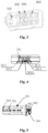
Fig. 1 is a schematic diagram of an electric switch according to an embodiment of the present disclosure. -
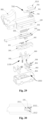
Fig. 2 is an exploded view of the electric switch according to an embodiment of the present disclosure. -
Fig. 3 is a schematic diagram of an internal structure of the electric switch according to an embodiment of the present disclosure. -
Fig. 4 is a schematic diagram of a movable contact frame according to an embodiment of the present disclosure. -
Fig. 5 is a schematic diagram of the movable contact frame according to an embodiment of the present disclosure, in which a brush and a snap-action resilient member are mounted. -
Fig. 6 is a schematic diagram of the movable contact frame from another perspective according to an embodiment of the present disclosure, in which the brush and the snap-action resilient member are mounted. -
Fig. 7 is a schematic diagram of a lock member according to an embodiment of the present disclosure. -
Fig. 8 is a schematic diagram of an actuator according to an embodiment of the present disclosure. -
Fig. 9 schematically shows cross sections of parts of the electric switch according to an embodiment of the present disclosure. -
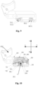
Fig. 10 is a schematic diagram of the electric switch in an initial state according to an embodiment of the present disclosure. -
Fig. 11 is another schematic diagram of the electric switch in an initial state according to an embodiment of the present disclosure. -
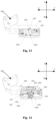
Fig. 12 is a schematic diagram of the electric switch in a first motion state according to an embodiment of the present disclosure. -
Fig. 13 is another schematic diagram of the electric switch in the first motion state according to an embodiment of the present disclosure. -
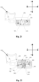
Fig. 14 is a schematic diagram of the electric switch in a second motion state according to an embodiment of the present disclosure. -
Fig. 15 is another schematic diagram of the electric switch in the second motion state according to an embodiment of the present disclosure. -
Fig. 16 is a schematic diagram of the electric switch in a third motion state according to an embodiment of the present disclosure. -
Fig. 17 is another schematic diagram of the electric switch in the third motion state according to an embodiment of the present disclosure. -
Fig. 18 is a schematic diagram of the electric switch in a fourth motion state according to an embodiment of the present disclosure. -
Fig. 19 is another schematic diagram of the electric switch in the fourth motion state according to an embodiment of the present disclosure. -
Fig. 20 is a schematic diagram of the electric switch in a fifth motion state according to an embodiment of the present disclosure. -
Fig. 21 is another schematic diagram of the electric switch in the fifth motion state according to an embodiment of the present disclosure. -
Fig. 22 is a schematic diagram of the electric switch in a sixth motion state according to an embodiment of the present disclosure. -
Fig. 23 is another schematic diagram of the electric switch in the sixth motion state according to an embodiment of the present disclosure. -
Fig. 24 is a schematic diagram of the electric switch in a seventh motion state according to an embodiment of the present disclosure. -
Fig. 25 is another schematic diagram of the electric switch in the seventh motion state according to an embodiment of the present disclosure. -
Fig. 26 is a schematic diagram of the electric switch in an eighth motion state according to an embodiment of the present disclosure. -
Fig. 27 is another schematic diagram of the electric switch in the eighth motion state according to an embodiment of the present disclosure. -
Fig. 28 is a schematic diagram of an electric switch according to another embodiment of the present disclosure. -
Fig. 29 is an exploded view of the electric switch according to another embodiment of the present disclosure. -
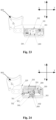
Fig. 30 is a schematic diagram of parts of the electric switch according to another embodiment of the present disclosure. -
Fig. 31 is another schematic diagram of some parts of the electric switch according to another embodiment of the present disclosure. -
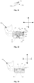
Fig. 32 is a schematic diagram of the electric switch in an initial state according to another embodiment of the present disclosure. -
Fig. 33 is another schematic diagram of the electric switch in the initial state according to another embodiment of the present disclosure. -
Fig. 34 is a schematic diagram of the electric switch in a first motion state according to another embodiment of the present disclosure. -
Fig. 35 is another schematic diagram of the electric switch in the first motion state according to another embodiment of the present disclosure. -
Fig. 36 is a schematic diagram of the electric switch in a second motion state according to another embodiment of the present disclosure. -
Fig. 37 is another schematic diagram of the electric switch in the second motion state according to another embodiment of the present disclosure. -
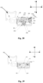
Fig. 38 is a schematic diagram of the electric switch in a third motion state according to another embodiment of the present disclosure. -
Fig. 39 is another schematic diagram of the electric switch in the third motion state according to another embodiment of the present disclosure. -
Fig. 40 is a schematic diagram of the electric switch in a fourth motion state according to another embodiment of the present disclosure. -
Fig. 41 is another schematic diagram of the electric switch in the fourth motion state according to another embodiment of the present disclosure. -
Fig. 42 is a schematic diagram of the electric switch in a fifth motion state according to another embodiment of the present disclosure. -
Fig. 43 is another schematic diagram of the electric switch in the fifth motion state according to another embodiment of the present disclosure. -
Fig. 44 is a schematic diagram of the electric switch in a sixth motion state according to another embodiment of the present disclosure. -
Fig. 45 is another schematic diagram of the electric switch in the sixth motion state according to another embodiment of the present disclosure. -
Fig. 46 is a schematic diagram of the electric switch in a seventh motion state according to another embodiment of the present disclosure. -
Fig. 47 is another schematic diagram of the electric switch in the seventh motion state according to another embodiment of the present disclosure. -
Fig. 48 is a schematic diagram of the electric switch in an eighth motion state according to another embodiment of the present disclosure. -
Fig. 49 is another schematic diagram of the electric switch in the eighth motion state according to another embodiment of the present disclosure. - In the drawings: 100, casing; 101, first groove; 1011, sliding hole; 1012, hanger; 1013, support surface; 1014, resin; 200, actuator; 201, drive portion; 202, abutting portion; 203, reset element; 204, third mounting slot; 205, second groove; 300, movable contact frame; 301, accommodating space; 3011, first abutment surface; 3012, second abutment surface; 3013, third abutment surface; 3014, fourth abutment surface; 3015, strip-shaped hole; 302, retaining portion; 304, first mounting slot; 305, second mounting slot; 306, contact spring; 400, snap-action resilient member; 401, first spring; 402, second spring; 500, first lock member; 600, second lock member; 700, signal switch; 701, brush; 702, circuit board; 7021, limit hole; 703, first terminal; 7031, first counterbore; 704, first resilient element; 705, brush holder; 7051, protrusion; 800, contact switch; 801, movable contact; 802, fixed contact; 803, second terminal; 8031, second counterbore; 900, button; 1000, mounting cavity; 1100, lock mechanism; 561, mounting groove; 562, second resilient element; s1, first slope; s2, second slope; a, lock portion; b, unlock portion; c, reset portion.
- The embodiments of the present disclosure are described in detail below. Examples of the embodiments are shown in the accompanying drawings, in which the same or similar reference numerals indicate the same or similar elements or elements with the same or similar functions. The embodiments described are exemplary, and are intended to explain the present disclosure, but should not be construed as limiting the scope of the present disclosure.
- In order to better understand the above technical solutions, the exemplary embodiments of the present disclosure will be further described in detail below with reference to the accompanying drawings. Although the drawings show exemplary embodiments of the present disclosure, it should be understood that the present disclosure can be implemented in various forms and should not be limited by the embodiments set forth herein. On the contrary, these embodiments are intended to let the ordinary skill in the prior art more thoroughly understand the present disclosure.
- It should be noted that in the present disclosure, X direction is defined as the positive direction of the first direction; Y direction is defined as the negative direction of the first direction; M direction is defined as the positive direction of the second direction; and N direction is defined as the negative direction of the second direction.
- Referring to
Figs. 1-27 , this embodiment provides an electric switch, including acasing 100 and a mountingcavity 1000 provided in thecasing 100. The mountingcavity 1000 is provided with anactuator 200, amovable contact frame 300, a snap-actionresilient member 400, alock mechanism 1100, acontact switch 800 and asignal switch 700. Thelock mechanism 1100 includes afirst lock member 500 and asecond lock member 600. - Specifically, referring to
Figs. 2 ,4 ,6, 8 ,10 and11 , theactuator 200 is capable of reciprocating in the mountingcavity 1000 along a first direction. Theactuator 200 is provided with adrive portion 201 and anabutting portion 202 connected to thedrive portion 201, and the abuttingportion 202 moves together with thedrive portion 201. Themovable contact frame 300 is provided with anaccommodating space 301 and a retainingportion 302. The snap-actionresilient member 400 is arranged in theaccommodating space 301, and thedrive portion 201 is inserted in theaccommodating space 301 and moves together with theactuator 200. Thedrive portion 201 on theactuator 200 is capable of compressing the snap-actionresilient member 400 to allow the snap-actionresilient member 400 to store energy, that is, when theactuator 200 is driven to reciprocate in the first direction, thedrive portion 201 on theactuator 200 moves in theaccommodating space 301 and is allowed to contact the snap-actionresilient member 400 to compress the snap-actionresilient member 400 for energy storage. - Referring to
Figs. 2 ,7 ,10 and11 , thefirst lock member 500 and thesecond lock member 600 are arranged opposite to each other in the mountingcavity 1000, and a gap is arranged between thefirst lock member 500 and thesecond lock member 600. Each of thefirst lock member 500 and thesecond lock member 600 defines a lock portion a, an unlock portion b, and a reset portion c. One end of the reset portion c abuts in the mountingcavity 1000, and the reset portion c is compressed after subjected to a compression force from the abuttingportion 202 of theactuator 200 in a positive direction of a second direction. After the compression force is removed, there is a resetting force to allow the reset portion c to move in a negative direction of the second direction. The resetting force and the compression force have opposite directions. The resetting force enables the lock portion a to move in the negative direction of the second direction to let the retainingportion 302 be locked to limit the movement of themovable contact frame 300. The unlock portion b is pressed by the abuttingportion 202 of theactuator 200 to overcome the resetting force of the reset portion c to enable the lock portion a to depart from the retainingportion 302. When one lock portion a locks the retainingportion 302, the other lock portion a is disengaged from the retainingportion 302. It should be understood that when thefirst lock member 500 locks themovable contact frame 300, the resetting force of the reset portion c of thefirst lock member 500 enables the lock portion a of thefirst lock member 500 to lock the retainingportion 302. At this time, the lock portion a of thesecond lock member 600 departs from the retainingportion 302. When thesecond lock member 600 locks themovable contact frame 300, the resetting force of the reset portion c of thesecond lock member 600 enables the lock portion a of thesecond lock member 600 to lock the retainingportion 302. At this time, the lock portion a of thefirst lock member 500 departs from the retainingportion 302. - Referring to
Figs. 2 and9-11 , thesignal switch 700 includes abrush 701 and acircuit board 702. Thecircuit board 702 is arranged in the mountingcavity 1000, and thebrush 701 is arranged on themovable contact frame 300. Thecontact switch 800 includes amovable contact 801 and afixed contact 802. The fixedcontact 802 is arranged in the mountingcavity 1000, and themovable contact 801 is arranged on themovable contact frame 300. - Specifically, when the
actuator 200 is driven to move in the first direction, thedrive portion 201 moves in the first direction to compress the snap-actionresilient member 400 for energy storage. The abuttingportion 202 moves from one unlock portion b to the other unlock portion b and presses the other unlock portion b to enable the lock portion a corresponding to the other unlock portion b to depart from the retainingportion 302. The snap-actionresilient member 400 produces a snap action to release energy to drive themovable contact frame 300 to move in the first direction, so that thebrush 701 is driven to slide on thecircuit board 702 to switch thesignal switch 700 on/off, and themovable contact 801 is driven to move toward or away from the fixedcontact 802 to make themovable contact 801 be in contact with or separated from the fixedcontact 802, so as to allow thecontact switch 800 to be switched on/off. In other words, thedrive portion 201 and the abuttingportion 202 of theactuator 200 move in the first direction when theactuator 200 moves in the first direction. Thedrive portion 201 first compresses the snap-actionresilient member 400 to store energy, and at this time, one lock portion a locks the retainingportion 302. Theactuator 200 continues to move in the first direction, and the abuttingportion 202 presses the unlock portion b corresponding to the other lock portion a, so that the other lock portion a is separated from the retainingportion 302. At this time, themovable contact frame 300 is released from the restriction, so that the snap-actionresilient member 400 will suddenly produces a snap action to release energy and drive themovable contact frame 300 to move in the first direction, and thesignal switch 700 and thecontact switch 800 arranged in themovable contact frame 300 and the mountingcavity 1000 will be immediately switched on/off. - Referring to
Figs. 10-11 , when the electric switch is in an initial state, the snap-actionresilient member 400, thefirst lock member 500, and thesecond lock member 600 do not play a locking role, and theactuator 200 drives themovable contact frame 300 to move in the positive direction of the first direction to allow themovable contact frame 300 to contact thefirst lock member 500. At this time, thefirst lock member 500 locks themovable contact frame 300. When theactuator 200 continues to move in the positive direction of the first direction, the abuttingportion 202 presses the unlock portion b of thefirst lock member 500 to unlock themovable contact frame 300 until a critical position of unlocking is reached. At the same time, the snap-action resilient member mounted in the movable contact frame is subject to the compression force exerted in the positive direction of the first direction by thedrive portion 201 of theactuator 200 and is compressed to store energy. After themovable contact frame 300 is unlocked, the snap-actionresilient member 400 is released instantaneously, and themovable contact frame 300 moves quickly to enable thesignal switch 700 and thecontact switch 800 to be switched on instantaneously. At this time, thesecond lock member 600 locks themovable contact frame 300, which ensures that thecontact switch 700 is reliably switched on, and eliminates the contact bounce and the poor contact caused by improper operation, effectively preventing the contacts from being burned and prolonging the service life of the electric switch. When theactuator 200 is driven to move in the negative direction of the first direction to reset, the snap-actionresilient member 400 produces a reverse snap action to enable the electric switch to be switched off or on instantaneously. The snap-action force generated by the snap-actionresilient member 400 is a pure horizontal force, which is different from the diagonal snap-action force generated by the conventional electric switches which shortens the service life of the electric switch. Therefore, the horizontal force enables the electric switch of the present disclosure to have a prolonged service life and thus satisfy market demands. Thesignal switch 700 may be arranged at a front end or a rear end of a bottom of the mountingcavity 1000, so as to properly utilize the space. - In some embodiments, referring to
Figs. 6 and10 , the snap-actionresilient member 400 includes afirst spring 401 and asecond spring 402 arranged on two sides of thedrive portion 201. Thefirst spring 401 may be compressed by one side of thedrive portion 201 to store energy, and thesecond spring 402 may be compressed by the other side of thedrive portion 201 to store energy. In other words, when thedrive portion 201 moves in the positive direction of the first direction, thefirst spring 401 can be compressed by thedrive portion 201 to store energy; and when thedrive portion 201 moves in the negative direction of the first direction, thesecond spring 402 is compressed by the drive portion to store energy. It should be noted that in other examples, the snap-actionresilient member 400 may also adopt a single spring structure. For example, only the first spring is provided and the second spring is removed. In some embodiment, referring toFigs. 4 ,6 and10 , theaccommodating space 301 has afirst abutment surface 3011 and asecond abutment surface 3012 opposite to each other, and athird abutment surface 3013 and afourth abutment surface 3014 opposite to each other. One end of thefirst spring 401 abuts thefirst abutment surface 3011, and the other end of thefirst spring 401 abuts thesecond abutment surface 3012 and may contact thedrive portion 201. One end of thesecond spring 402 abuts thethird abutment surface 3013, and the other end of thesecond spring 402 abuts thefourth abutment surface 3014 and may contact thedrive portion 201. It should be understood that when thefirst spring 401 is in a free state, one end of thefirst spring 401 abuts thefirst abutment surface 3011, and the other end of thefirst spring 401 abuts thesecond abutment surface 3012. When thedrive portion 201 moves in the positive direction of the first direction, thedrive portion 201 contacts the end of thefirst spring 401 that abuts on thesecond abutment surface 3012, and thefirst spring 401 is compressed. Similarly, when thesecond spring 402 is in a free state, one end of thesecond spring 402 abuts thethird abutment surface 3013, and the other end of thesecond spring 402 abuts thefourth abutment surface 3014. When thedrive portion 201 moves in the positive direction of the first direction, thedrive portion 201 contacts the end of thesecond spring 402 that abuts on thefourth abutment surface 3014, and thesecond spring 402 is compressed. - Specifically, referring to
Figs. 4 and6 , a strip-shapedhole 3015 may be provided in theaccommodating space 301 for the movement of thedrive portion 201. One end of the strip-shapedhole 3015 is located between thefirst abutment surface 3011 and thesecond abutment surface 3012, and the other end of the strip-shapedhole 3015 is located between thethird abutment surface 3013 and thefourth abutment surface 3014. - In some embodiments, referring to
Fig. 5 , the retainingportion 302 is a convex block extending downward from a bottom surface of themovable contact frame 300. In some embodiments, there are two retainingportions 302 which are oppositely arranged on two sides of the strip-shapedhole 3015. - Referring to
Fig. 7 , the lock portion a is a column. When a side surface of thelock portion 302 contacts a side surface of the lock portion a, the lock portion a abuts against the retainingportion 302 to lock the retainingportion 302. When a bottom surface of the retainingportion 302 crosses the top surface of the lock portion a, the retainingportion 302 is separated from the side surface of the lock portion a. - In some embodiments, referring to
Figs. 7 and 8 , the unlock portion b is a block arranged on a side of the lock portion a. A top of the unlock portion b has a first slope s1, and the abuttingportion 202 has a second slope s2. The second slope s2 abuts against the first slope s1 to press the unlock portion b to overcome the resetting force of the reset portion c. In order to ensure the reliable pressing between the unlock portion b and the abuttingportion 202, each of the first slope s1 and the second slope s2 transitions to a plane after the first slope s1 and the second slope s2 contact with each other. That is, a plane is provided at the top of the unlock portion behind the first slope s1 for transition, and a plane is provided behind the second slope s2 of the abuttingportion 202 for transition. In addition, the first slope s1 of the unlock portion b of thefirst lock member 500 and the first slope s1 of the unlock portion b of thesecond lock member 600 are opposite to each other and have opposite inclination directions. The second slope s2 may include a front slope and a rear slope which respectively correspond to the first slope s1 of the unlock portion b of thefirst lock member 500 and the first slope s1 of the unlock portion b of thesecond lock member 600. There are two retainingportions 302, and each of thefirst lock member 500 and thesecond lock member 600 is provided with two lock portions a and two unlock portions b on both sides of the reset portion c. Theactuator 200 is provided with two abuttingportions 202. The retainingportions 302 correspond to the lock portions a on thefirst lock member 500 and the lock portions on thesecond lock member 600, respectively. The lock portions a and the unlock portions b have a one-to-one correspondence. The unlock portions b on thefirst lock member 500 and the unlock portions b on thesecond lock member 600 correspond to the abuttingportions 202, respectively. - The reset portion c has a mounting
groove 561 and a secondresilient element 562. One end of the secondresilient element 562 abuts in the mountinggroove 561, and the other end of the secondresilient element 562 abuts in the mountingcavity 1000. In other words, the secondresilient element 562 is partially inserted into the mountinggroove 561, and the secondresilient element 562 can be compressed after being pressed by the abuttingportion 202 of theactuator 200 in the positive direction of the second direction, and the end of the secondresilient element 562 away from the mountinggroove 561 abuts in the mountingcavity 1000. After the pressing force is removed, the elastic force caused by the compression of the secondresilient element 562 allows the reset portion c to have a resetting force in a negative direction of the second direction, and the direction of the resetting force is opposite to the direction of the pressing force. When the abuttingportion 202 presses the unlock portion b, the secondresilient element 562 is compressed by the pressing force of the abuttingportion 202 in the positive direction of the second direction, so that the lock portion a moves downward and separates from the retainingportion 302. The secondresilient element 562 may be a compression spring. In order to facilitate the mounting of thefirst lock member 500 and thesecond lock member 600, a limit post may be provided in the mountingcavity 1000 to mount the secondresilient element 562. - In some embodiments, referring to
Figs. 2-3 and9 , in terms of thesignal switch 700, thebrush 701 is arranged on themovable contact frame 300, and thecircuit board 702 is arranged in the mountingcavity 1000. When themovable contact frame 300 moves, thebrush 701 slides on thecircuit board 702; when thebrush 701 is connected to a conductive sheet on thecircuit board 702, thesignal switch 700 is switched on. When thebrush 701 fails to contact the conductive sheet on thecircuit board 702, thesignal switch 700 is switched off. Thebrush 701 slides horizontally or rotationally on thecircuit board 702. - Specifically, referring to
Figs. 2 ,5 and9 , the electric switch further includes afirst terminal 703, and thecircuit board 702 is mounted in the mountingcavity 1000 through thefirst terminal 703. Afirst mounting slot 304 may be provided on themovable contact frame 300, and thebrush 701 is mounted in thefirst mounting slot 304. When themovable contact frame 300 is assembled into the mountingcavity 1000, thebrush 701 contacts thecircuit board 702 and is located above thecircuit board 702. - In some embodiments, referring to
Figs. 2 and9 , thecircuit board 702 and thefirst terminal 703 are electrically connected through the first resilient element 704; or thecircuit board 702 and thefirst terminal 703 are riveted to realize the electrical connection therebetween. - Referring to
Fig. 9 , in order to prevent foreign matters from entering the electric switch and ensure the protection capability of the electric switch, afirst counterbore 7031 is provided on thefirst terminal 703. In thefirst counterbore 7031, thefirst terminal 703 can be connected to an external conductor through a locking screw. - Referring to
Figs. 2 and3 , during the assembling of thecircuit board 702, a first fastener on thecasing 100 is inserted into alimit hole 7021 on thecircuit board 702, and thecircuit board 702 is pressed and held through a second fastener on thecasing 100, thereby ensuring that thecircuit board 702 is reliably fixed in the mountingcavity 1000. - In some embodiments, referring to
Figs. 2 ,5 and9 , themovable contact 801 of thecontact switch 800 is arranged on themovable contact frame 300, and the fixedcontact 802 of thecontact switch 800 is arranged in the mountingcavity 1000. When themovable contact frame 300 moves in the first direction, themovable contact 801 contacts the fixedcontact 802 to form a conduction circuit; or themovable contact 801 is separated from the fixedcontact 802, and the conduction circuit is cut off. That is, the movement of themovable contact frame 300 can drive themovable contact 801 to move close to or away from the fixedcontact 802, so that themovable contact 801 and the fixedcontact 802 are in contact with or separated from each other, thereby controlling the on/off of the circuit. - Referring to
Figs. 2 and5 , the electric switch further includes asecond terminal 803, and the fixedcontact 802 can be mounted in the mountingcavity 1000 through asecond terminal 803. Themovable contact frame 300 may be provided with asecond mounting slot 305, and themovable contact 801 is mounted in thesecond mounting slot 305. When themovable contact frame 300 is assembled into the mountingcavity 1000, themovable contact 801 and the fixedcontact 802 are arranged opposite to each other, and there is a gap between themovable contact 801 and the fixedcontact 802. Furthermore, themovable contact 801 is connected to one end of acontact spring 306, and the end of thecontact spring 306 away from themovable contact 801 is mounted in thesecond mounting slot 305. - Referring to
Figs. 2 and9 , in order to prevent foreign matters from entering the electric switch and ensure the protection capability of the electric switch, asecond counterbore 8031 is provided on thesecond terminal 803. In thesecond counterbore 8031, thesecond terminal 803 can be connected to an external conductor through a locking screw. - Referring to
Figs. 2 and5 , thesignal switch 700 may be arranged on a left side of thefirst lock member 500, or on a right side of thesecond lock member 600. Correspondingly, thecontact switch 800 may be arranged on the right side of thesecond lock member 600, or on the left side of thefirst lock member 500. - In some embodiments, referring to
Figs. 2 and10 , theactuator 200 and the mountingcavity 1000 are connected by areset element 203, and one end of theactuator 200 penetrates the mountingcavity 1000 and is hinged with abutton 900. It should be understood that the reciprocating movement of theactuator 200 in the first direction in the mountingcavity 1000 is driven by artificially pressing thebutton 900 and the resetting force of thereset element 203. Specifically, theactuator 200 is provided with athird mounting slot 204, and the mountingcavity 1000 is provided with an extension block extending to thethird mounting slot 204. One end of thereset element 203 abuts against thethird mounting slot 204, and the other end of thereset element 203 abuts against the extension block. Thereset element 203 may be a spring. - Referring to
Figs. 2 ,4 and8 , thedrive portion 201 of theactuator 200 is a protruding rod, and thedrive portion 201 is formed by extending downward from the bottom surface of theactuator 200. The abuttingportion 202 is formed by extending outward from the side surface of theactuator 200. When theactuator 200 is assembled into the mountingcavity 1000, thedrive portion 201 is inserted in the strip-shapedhole 3015 and is movable in the strip-shapedhole 3015. - The snap and locking actions of the electric switch will be described below with reference to
Figs. 10-27 . - Referring to
Figs. 4 ,10 and11 , the electric switch is in the initial state, and thefirst lock member 500 does not play a locking role. The unlock portions b of thefirst lock member 500 abuts on a top of the mountingcavity 1000, and the unlock portions b of thesecond lock member 600 abuts on the plane of the abuttingportion 202 of theactuator 200. Thefirst spring 401 is located in themovable contact frame 300, and both ends of thefirst spring 401 abut on thefirst abutment surface 3011 and thesecond abutment surface 3012, respectively. One end of thesecond spring 402 abuts on thethird abutment surface 3013 of themovable contact frame 300, and the other end of thesecond spring 402 abuts on thedrive portion 201 of theactuator 200. - Referring to
Figs. 2 ,4 ,12 and13 , thebutton 900 is pressed, and theactuator 200 is driven to move in the positive direction of the first direction. Thedrive portion 201 of theactuator 200 is located on thesecond abutment surface 3012 and thefourth abutment surface 3014 of themovable contact frame 300, and thefirst spring 401 and thesecond spring 402 are located in themovable contact frame 300. At this time, thedrive portion 201 of theactuator 200 does not compress thefirst spring 401 and thesecond spring 402 for energy storage. The unlock portion b of thefirst lock member 500 still abuts on the top of the mountingcavity 1000, and the abuttingportion 202 of the actuator 200 starts to move away from thesecond lock member 600 and approach thefirst lock member 500. Themovable contact frame 300 is still in the initial state and has not moved. - Referring to
Figs. 2 ,4 ,14 and15 , when thebutton 900 is continuously pressed, theactuator 200 is driven to move in the positive direction of the first direction. Thedrive portion 201 of the actuator 200 contacts and interacts with thefirst spring 401 in themovable contact frame 300, and themovable contact frame 300 is driven to move in the positive direction of the first direction. When themovable contact frame 300 moves for a certain displacement, the retainingportion 302 of themovable contact frame 300 abuts on the lock portion a of thefirst lock member 500. At this time, thefirst lock member 500 locks themovable contact frame 300, and themovable contact frame 300 is not able to move. Thedrive portion 201 of theactuator 200 is located between thesecond abutment surface 3012 and thefourth abutment surface 3014 of themovable contact frame 300. Thefirst spring 401 and thesecond spring 402 are located in themovable contact frame 300. Thedrive portion 201 of theactuator 200 does not exert a compression force on thefirst spring 401 and thesecond spring 402 for energy storage. - Referring to
Figs. 2 ,16 and17 , thebutton 900 is continuously pressed, and theactuator 200 is driven to move in the positive direction of the first direction. Since themovable contact frame 300 is locked by thefirst lock member 500, themovable contact frame 300 is not capable of moving, and thefirst spring 401 in themovable contact frame 300 is continuously compressed by thedrive portion 201 for energy storage. The unlock portion b of thefirst lock member 500 is pressed by the front slope of the abuttingportion 202 of theactuator 200 and moves in the positive direction of the second direction until the critical state of unlocking is reached. - Referring to
Figs. 2 ,18 and19 , when thebutton 900 is continuously pressed, theactuator 200 continues to move in the positive direction of the first direction. The unlock portion b of thefirst lock member 500 is pressed by the abuttingportion 202 of theactuator 200, and thefirst lock member 500 moves in the positive direction of the second direction. Themovable contact frame 300 is unlocked, and thefirst spring 401 immediately jumps to release energy, and themovable contact frame 300 quickly moves in the positive direction of the first direction. Finally, themovable contact 801 contacts the fixedcontact 802, causing thecontact switch 800 to be switched on instantaneously; and thebrush 701 slides on thecircuit board 702 and contacts the conductive sheet on thecircuit board 702, so that thesignal switch 700 is switched on. When themovable contact frame 300 rapidly moves in the positive direction of the first direction, thesecond lock member 600 moves in the negative direction of the second direction under the action of the reset portion c to lock themovable contact frame 300. This ensures the reliable connection between themovable contact 801 and the fixedcontact 802 and the reliable connection between thebrush 701 and the conductive sheet on thecircuit board 702, avoiding the burning of the contacts caused by the bounce, the shaking or the undesirable phenomenon of non-communication of contacts, thus prolonging the service life of the electric switch. - Referring to
Figs. 2 ,20 and21 , when thebutton 900 is continuously pressed, theactuator 200 continues to move in the positive direction of the first direction, and thefirst spring 401 is compressed by thedrive portion 201 of theactuator 200 to store energy. At this time, thefirst lock member 500 is in an unlocked state, and thesecond lock member 600 still locks themovable contact frame 300, and thecontact switch 800 and thesignal switch 700 are still in an on state. - Referring to
Figs. 2 ,4 ,7 ,22 and23 , thebutton 900 is released, and theactuator 200 moves in the negative direction of the first direction under the action of the elastic force of thereset element 203 and thefirst spring 401. Thedrive portion 201 is located between thesecond abutment surface 3012 and thefourth abutment surface 3014 of themovable contact frame 300, and thesecond spring 402 is not compressed for the energy storage by thedrive portion 201. The rear slope of the abuttingportion 202 abuts on the first slope s1 of thesecond lock member 600, and thesecond lock member 600 still locks themovable contact frame 300. Thecontact switch 800 and thesignal switch 700 are still in the on state. - Referring to
Figs. 2 ,24 and25 , thebutton 900 is released, and theactuator 200 continues to move in the negative direction of the first direction. Since thesecond lock member 600 locks themovable contact frame 300, thedrive part 201 compresses thesecond spring 402 for energy storage. The unlock portion b of thesecond lock member 600 is pressed by the rear slope of the abuttingportion 202 of theactuator 200 and moves in the positive direction of the second direction until the critical state of unlocking is reached. - Referring to
Figs, 2 ,26 and27 , thebutton 900 is released, and theactuator 200 continues to move in the negative direction of the first direction. The unlock portion b of thesecond lock member 600 is pressed by the abuttingportion 202 of theactuator 200, and thesecond lock member 600 moves in the positive direction of the second direction to unlock themovable contact frame 300. Thesecond spring 402 suddenly releases energy to drive themovable contact frame 300 to move rapidly in the negative direction of the first direction, so that thecontact switch 800 and thesignal switch 700 are momentarily disconnected. When themovable contact frame 300 rapidly moves in the negative direction of the first direction, the lock portion a of thefirst lock member 500 moves in the negative direction of the second direction under the action of the reset portion c, and abuts against the retainingportion 302 of themovable contact frame 300 to lock themovable contact frame 300 until the button returns to the initial position. At this time, the electric switch is in the initial state. - Referring to
Figs. 28-49 , another electrical switch provided by the present disclosure will be described in detail below. The structure and principle of the electric switch are roughly the same as those in the Embodiment 1, and the same parts will not be described herein. - In this embodiment, referring to
Figs. 28-31 , the electric switch includes acasing 100, a mountingcavity 1000 provided in thecasing 100. Anactuator 200, amovable contact frame 300, a snap-actionresilient member 400, alock mechanism 1100, acontact switch 800, and asignal switch 700 are provided in the mountingcavity 1000. Thelock mechanism 1100 includes afirst lock member 500 and asecond lock member 600. - Referring to
Figs. 28-31 , thesignal switch 700 includes abrush 701 and acircuit board 702. Thecircuit board 702 is arranged on thecasing 100, and thebrush 701 is connected to theactuator 200, so thatbrush 701 is driven to move through the movement of theactuator 200. - Specifically, referring to
Figs. 29-31 , afirst groove 101 is provided on thecasing 100, and a slidinghole 1011 is provided in thefirst groove 101. Abrush holder 705 is also provided in thefirst groove 101, and thebrush 701 is mounted on thebrush holder 705. In addition, aprotrusion 7051 extends downward from thebrush holder 705. Theprotrusion 7051 is inserted into the slidinghole 1011 and is slidable in the slidinghole 1011. Theactuator 200 is provided with asecond groove 205. When theactuator 200 is assembled in the mountingcavity 1000, theprotrusion 7051 passes through the slidinghole 1011 and is inserted into thesecond groove 205. In this way, when theactuator 200 moves, theprotrusion 7051 can abut against the inner side walls of thesecond groove 205, and theprotrusion 7051 is driven to slide in the slidinghole 1011 with the movement of theactuator 200. As a result, thebrush 701 is driven to slide by thebrush holder 705. - Furthermore, referring to
Figs. 29-31 , ahanger 1012 and asupport surface 1013 are respectively provided on an inner side wall of thefirst groove 101. Thesupport surface 1013 is located below thehanger 1012. Thecircuit board 702 is attached to thesupport surface 1013 and hung by thehanger 1012, and then sealed by aresin 1014, so that thecircuit board 702 is disposed on thecasing 100 and above thebrush 701, and thecircuit board 702 can contact thebrush 701. - The
signal switch 700 is arranged on an upper end of a rear of thecasing 100, so that the arrangement of the signal switch is diversified, facilitating the proper use of space. - The sudden snap and lock actions of the electric switch are described below with reference to
Figs. 32-49 . - Referring to
Figs. 4 ,32 and 33 , the electric switch is in the initial state, and thefirst lock member 500 does not play a locking role. The unlock portion b of thefirst lock member 500 abuts on the top of the mountingcavity 1000, and the unlock portion b of thesecond lock member 600 abuts on the plane of the abuttingportion 202 of theactuator 200. Thefirst spring 401 is located in themovable contact frame 300, and two ends of thefirst spring 401 abut on thefirst abutment surface 3011 and thesecond abutment surface 3012, respectively. One end of thesecond spring 402 abuts on thethird abutment surface 3013 of themovable contact frame 300, and the other end of thesecond spring 402 abuts on thedrive portion 201 of theactuator 200. For thesignal switch 700, theprotrusion 7051 is not in contact with the right inner side wall of thesecond groove 205. - Referring to
Figs. 4 ,20 ,34 and 35 , when thebutton 900 is pressed, theactuator 200 is driven to move in the positive direction of the first direction. Thedrive portion 201 of theactuator 200 is located between thesecond abutment surface 3012 and thefourth abutment surface 3014 of themovable contact frame 300, and thefirst spring 401 and thesecond spring 402 are located in themovable contact frame 300. Thedrive portion 201 of theactuator 200 does not compress thefirst spring 401 and thesecond spring 402. The unlock portion b of thefirst lock member 500 still abuts on the top of the mountingcavity 1000, and the abuttingportion 202 of the actuator 200 starts to move away from thesecond lock member 600 and approach thefirst lock member 500. Themovable contact frame 300 is still in the initial state and has not moved. For thesignal switch 700, theprotrusion 7051 is displaced in thesecond groove 205, and the position of theprotrusion 7051 changes, but it still does not contact the right inner side wall of thesecond groove 205. - Referring to
Figs. 4 ,20 ,36 and 37 , when thebutton 900 is continuously pressed, theactuator 200 is driven to move in the positive direction of the first direction. Thedrive portion 201 of the actuator 200 contacts and interacts with thefirst spring 401 in themovable contact frame 300, themovable contact frame 300 is driven to move in the positive direction of the first direction. When themovable contact frame 300 moves for a certain displacement, the retainingportion 302 of themovable contact frame 300 abuts on the lock portion a of thefirst lock member 500. At this time, thefirst lock member 500 locks themovable contact frame 300, and themovable contact frame 300 is not capable of moving. Thedrive portion 201 of theactuator 200 is located between thesecond abutment surface 3012 and thefourth abutment surface 3014 of themovable contact frame 300. Thefirst spring 401 and thesecond spring 402 are located in themovable contact frame 300. Thedrive portion 201 of theactuator 200 does not compress thefirst spring 401 and thesecond spring 402. For thesignal switch 700, theprotrusion 7051 is displaced in thesecond groove 205, and the position of theprotrusion 7051 changes, but it still does not contact the right inner side wall of thesecond groove 205. - Referring to
Figs. 20 ,38 and 39 , when thebutton 900 is continuously pressed, theactuator 200 is driven to move in the positive direction of the first direction. Since themovable contact frame 300 is locked by thefirst lock member 500, themovable contact frame 300 does not move. Thefirst spring 401 in themovable contact frame 300 is compressed by thedrive portion 201 for energy storage. The unlock portion b of thefirst lock member 500 is pressed by the front slope of the abuttingportion 202 of theactuator 200 and moves in the positive direction of the second direction until the critical state of unlocking is reached. For thesignal switch 700, theprotrusion 7051 is displaced in theactuation groove 205, the position of theprotrusion 7051 changes, and theprotrusion 7051 just contacts the right inner side wall of thesecond groove 205. - Referring to
Figs. 20 ,40 and 41 , when thebutton 900 is continuously pressed, theactuator 200 continues to move in the positive direction of the first direction. Theprotrusion 7051 is in contact with the right side wall of thesecond groove 205, and theprotrusion 7051 is driven to move under the movement of theactuator 200, thereby driving thebrush 701 to slide on thecircuit board 702 and contact the conductive sheet on thecircuit board 702 to switch on thesignal switch 700. The unlock portion b of thefirst lock member 500 is pressed by the abuttingportion 202 of theactuator 200, and thefirst lock member 500 moves in the positive direction of the second direction to unlock themovable contact frame 300. Thefirst spring 401 immediately produces a snap action to release energy, and themovable contact frame 300 moves rapidly in the positive direction of the first direction. Themovable contact 801 contacts the fixedcontact 802, causing thecontact switch 800 to be switched on instantaneously. When themovable contact frame 300 rapidly moves in the positive direction of the first direction, thesecond lock member 600 moves in the negative direction of the second direction under the action of the reset portion c to lock themovable contact frame 300. This ensures the reliable connection between themovable contact 801 and the fixedcontact 802 and the reliable connection between thebrush 701 and the conductive sheet on thecircuit board 702, avoiding the burning of the contacts caused by the bounce, the shaking or the undesirable phenomenon of non-communication of contacts, thus prolonging the service life of the electric switch. - Referring to
Figs. 20 ,42 and 43 , when thebutton 900 is continuously pressed, theactuator 200 continues to move in the positive direction of the first direction, and thefirst spring 401 is compressed by thedrive portion 201 of theactuator 200 to store energy. At this time, thefirst lock member 500 is in an unlocked state, and thesecond lock member 600 still locks themovable contact frame 300, and thecontact switch 800 and thesignal switch 700 are still in an on state. - Referring to
Figs. 4 ,20 ,44 and 45 , thebutton 900 is released, and theactuator 200 moves in the negative direction of the first direction under the action of the elastic force of thereset element 203 and thefirst spring 401. Thedrive portion 201 is located between thesecond abutment surface 3012 and thefourth abutment surface 3014 of themovable contact frame 300, and thesecond spring 402 is not compressed for the energy storage by thedrive portion 201. The rear slope of the abuttingportion 202 abuts on the first slope s1 of thesecond lock member 600, and thesecond lock member 600 still locks themovable contact frame 300. Thecontact switch 800 and thesignal switch 700 are still in the on state. - Referring to
Figs. 20 ,46 and 47 , when thebutton 900 is released, theactuator 200 continues to move in the negative direction of the first direction. Since thesecond lock member 600 locks themovable contact frame 300, thedrive part 201 compresses thesecond spring 402 for energy storage. The unlock portion b of thesecond lock member 600 is pressed by the rear slope of the abuttingportion 202 of theactuator 200 and moves in the positive direction of the second direction until the critical state of unlocking is reached. For thesignal switch 700, theprotrusion 7051 is displaced in thesecond groove 205, and the position of theprotrusion 7051 changes, and theprotrusion 7051 contacts the left inner side wall of thesecond groove 205. - Referring to
Figs, 4 ,20 ,48 and 49 , when thebutton 900 is released, theactuator 200 drives thebrush 701 to reset, and thesignal switch 700 is switched off instantaneously. Thesecond lock member 600 is unlocked, and thesecond spring 402 suddenly releases energy to drive themovable contact frame 300 to move rapidly in the negative direction of the first direction, so that thecontact switch 800 is switched off instantaneously. When themovable contact frame 300 rapidly moves in the negative direction of the first direction, the lock portion a of thefirst lock member 500 moves upward under the action of the reset portion c and abuts the retainingportion 302 of themovable contact frame 300 for locking themovable contact frame 300 until the button returns to the initial position. At this time, the electric switch returns to the initial state. - In some embodiments, some structures of the electric switch can adopt existing structures, which will not be described in detail herein.
- In the description of the present disclosure, it should be understood that the directions and position relationship indicated by the terms such as "center", "longitudinal", "transverse", "length", "width", "thickness", "upper", "lower", "front", " "rear", "left", "right", "vertical", "horizontal", "top", "bottom", "inner", "outer", "clockwise", "counterclockwise" are based on the orientation or position relationship shown in the drawings, which is only for the convenience of describing the present invention and simplifying the description, and does not indicate or imply that the device or element referred to must have a specific orientation and be constructed and operated in a specific orientation. Therefore, such terms should not be understood as a limitation to the present disclosure.
- In addition, the terms "first" and "second" are only used for descriptive purposes, and cannot be understood as indicating or implying relative importance or implicitly indicating the number of indicated technical features. Thus, the features defined with "first" and "second" may explicitly or implicitly include one or more of these features. In the description of the present invention, unless specified, the term "plurality" means two or more.
- In the present disclosure, unless specified, the terms such as "mount", "connect", "link", "fix" should be understood in a broad sense. For example, "connect" may result in a fixed connection, a detachable connection, or an integrated configuration of elements. The elements may be connected mechanically or electrically; or directly connected or indirectly connected through an intermediate medium. Alternatively, two elements may be in communication or interact with each other unless specified. For the skilled in the art, the specific meanings of the above terms in the present invention can be understood according to specific conditions.
- In the present disclosure, unless specified, when a first feature is located "above" or "below" the second feature, the first and second features may contact each other in a direct manner or through another feature located therebetween. Moreover, terms "on", "above" and "over" indicate that the second feature is directly above or obliquely above the second feature, or simply mean that the level of the first feature is higher than that of the second feature. Terms "under", "below" and "beneath" indicate that the second feature is directly below or obliquely below the second feature, or simply mean that the level of the first feature is lower than that of the second feature.
- In the description of the present disclosure, terms "an embodiment", "some embodiments", "examples", "some examples", or "some examples" etc. indicate that the specific feature, structure, material or characteristic described in combination with the embodiment or example is included in at least one embodiment or example of the present disclosure. These terms should not be understood as necessarily referring to the same embodiment or example. Moreover, the described specific features, structures, materials or characteristics can be combined in any one or more embodiments or examples in a proper manner. In addition, different embodiments or examples described herein can be combined by those skilled in the art.
Claims (9)
- An electric switch, comprising a casing (100), a mounting cavity (1000) provided in the casing (100), and an actuator (200), a movable contact frame (300), a snap-action resilient member (400), a lock mechanism (1100), a contact switch (800) and a signal switch (700) that are provided in the mounting cavity (1000);characterized in that the actuator (200) is capable of reciprocating in the mounting cavity (1000) along a first direction;the movable contact frame (300) is provided with a retaining portion (302);the snap-action resilient member (400) is arranged in the movable contact frame (300), and is configured to be compressed by the actuator (200) with movement of the actuator (200);the lock mechanism (1100) comprises a first lock member (500) and a second lock member (600); and the first lock member (500) and the second lock member (600) are configured to reciprocate in the mounting cavity (1000) with the movement of the actuator (200) in a second direction to lock or unlock the retaining portion (302);the signal switch (700) comprises a brush (701) and a circuit board (702); the brush (701) is arranged on the movable contact frame (300), and the circuit board (702) is arranged in the mounting cavity (1000);the contact switch (800) comprises a movable contact (801) and a fixed contact (802); the movable contact (801) is arranged on the movable contact frame (300), and the fixed contact (802) is arranged in the mounting cavity (1000);when the actuator (200) is driven to move along the first direction, the first lock member (500) locks the retaining portion (302), and the second lock member (600) does not lock the retaining portion (302), and the snap-action resilient member (400) is compressed by the actuator (200) for energy storage; when the actuator (200) is driven to continuously move along the first direction, the first lock member (500) unlocks the retaining portion (302), and the snap-action resilient member (400) produces a snap action to release energy to drive the movable contact frame (300) to move, so that the brush (701) is driven to slide on the circuit board (702) to switch on/off the signal switch (700); at the same time, the movable contact (801) is driven to move close to or away from the fixed contact (802), so that the movable contact (801) is in contact with or separated from the fixed contact (802), allowing the contact switch (800) to be switched on/off; during the movement of the movable contact frame (300), the second lock member (600) locks the retaining portion (302);wherein the actuator (200) comprises a drive portion (201) and an abutting portion (202) connected to the drive portion (201); the abutting portion (202) is capable of moving with the drive portion (201); the drive portion (201) is inserted into the movable contact frame (300) and moves with the actuator (200); the drive portion (201) is capable of compressing the snap-action resilient member (400) to allow the snap-action resilient member (400) to store energy; and the abutting portion (202) is capable of abutting against the first lock member (500) or the second lock member (600) to drive the first lock member (500) or the second lock member (600) to unlock the retaining portion (302);each of the first lock member (500) and the second lock member (600) comprises a lock portion (a), an unlock portion (b) and a reset portion (c); one end of the reset portion (c) abuts in the mounting cavity (1000), and the reset portion (c) is able to be compressed when subjected to a compression force exerted by the actuator (200) in the second direction; when the compression force is removed, the reset portion (c) has a reset force which is in the second direction and opposite to the compression force; the reset force allows the lock portion (a) to move along the second direction and lock the retaining portion (302) to limit the movement of the movable contact frame (300); the unlock portion (b) is pressed by the actuator (200) to overcome the reset force of the reset portion (c) to allow the lock portion (a) to be detached from the retaining portion (302)
- The electric switch according to claim 1, characterized in that the snap-action resilient member (400) comprises a first spring (401) and a second spring (402) which are respectively arranged at two sides of the drive portion (201); the first spring (401) is able to be compressed by one side of the drive portion (201) for energy storage, and the second spring (402) is able to be compressed by the other side of the drive portion (201) for energy storage.
- The electric switch according to claim 1, characterized by further comprising:a first terminal (703); anda second terminal (803);wherein the circuit board (702) is mounted in the mounting cavity (1000) through the first terminal (703), and the fixed contact (802) is mounted in the mounting cavity (1000) through the second terminal (803).
- The electric switch according to claim 3, characterized in that the circuit board (702) is electrically connected to the first terminal (703) through a first resilient element (704); or the circuit board (702) and the first terminal (703) are riveted.
- The electric switch according to claim 3, characterized in that the first terminal (703) is provided with a first counterbore (7031), and in the first counterbore (7031), the first terminal (703) is connected to an external conductor through a first locking screw; the second terminal (803) is provided with a second counterbore (8031); and in the second counterbore (8031), the second terminal (803) is connected to the external conductor through a second locking screw.
- The electric switch according to claim 1, characterized in that a first mounting slot (304) and a second mounting slot (305) are respectively arranged on two sides of the retaining portion (302) of the movable contact frame (300); the brush (701) is arranged in the first mounting slot (304), and the movable contact (801) is arranged in the second mounting slot (305).
- An electric switch, comprising a casing (100), a mounting cavity (1000) provided in the casing (100), and an actuator (200), a movable contact frame (300), a snap-action resilient member (400), a lock mechanism (1100), a contact switch (800) and a signal switch (700) that are provided in the mounting cavity (1000);characterized in that the actuator (200) is capable of reciprocating in the mounting cavity (1000) along a first direction;the movable contact frame (300) is provided with a retaining portion (302);the snap-action resilient member (400) is arranged in the movable contact frame (300), and is configured to be compressed by the actuator (200) with movement of the actuator (200);the lock mechanism (1100) comprises a first lock member (500) and a second lock member (600); and the first lock member (500) and the second lock member (600) are configured to reciprocate in the mounting cavity (1000) with the movement of the actuator (200) in a second direction to lock or unlock the retaining portion (302);the signal switch (700) comprises a brush (701) and a circuit board (702); the brush (701) is connected to the actuator (200), so that the actuator (200) drives the brush (701) to move; and the circuit board (702) is arranged on the casing (100);the contact switch (800) comprises a movable contact (801) and a fixed contact (802); the movable contact (801) is arranged on the movable contact frame (300), and the fixed contact (802) is arranged in the mounting cavity (1000);when the actuator (200) is driven to move along the first direction, the first lock member (500) locks the retaining portion (302), and the second lock member (600) does not lock the retaining portion (302), and the snap-action resilient member (400) is compressed by the actuator (200) for energy storage; when the actuator (200) is driven to continuously move along the first direction, the first lock member (500) unlocks the retaining portion (302), and the snap-action resilient member (400) produces a snap action to release energy to drive the movable contact frame (300) to move, so that the brush (701) is driven to slide on the circuit board (702) to switch on/off the signal switch (700); at the same time, the movable contact (801) is driven to move close to or away from the fixed contact (802), so that the movable contact (801) is in contact with or separated from the fixed contact (802), allowing the contact switch (800) to be switched on/off; during the movement of the movable contact frame (300), the second lock member (600) locks the retaining portion (302), wherein the actuator (200) comprises a drive portion (201) and an abutting portion (202) connected to the drive portion (201); the abutting portion (202) is capable of moving with the drive portion (201); the drive portion (201) is inserted into the movable contact frame (300) and moves with the actuator (200); the drive portion (201) is capable of compressing the snap-action resilient member (400) to allow the snap-action resilient member (400) to store energy; and the abutting portion (202) is capable of abutting against the first lock member (500) or the second lock member (600) to drive the first lock member (500) or the second lock member (600) to unlock the retaining portion (302);each of the first lock member (500) and the second lock member (600) comprises a lock portion (a), an unlock portion (b) and a reset portion (c); one end of the reset portion (c) abuts in the mounting cavity (1000), and the reset portion (c) is able to be compressed when subjected to a compression force exerted by the actuator (200) in the second direction; when the compression force is removed, the reset portion (c) has a reset force which is in the second direction and opposite to the compression force; the reset force allows the lock portion (a) to move along the second direction and lock the retaining portion (302) to limit the movement of the movable contact frame (300); the unlock portion (b) is pressed by the actuator (200) to overcome the reset force of the reset portion (c) to allow the lock portion (a) to be detached from the retaining portion (302).
- The electric switch according to claim 7, characterized in that the casing (100) is provided with a first groove (101), and a brush holder (705) is provided in the first groove(101); and the brush (701) is arranged on the brush holder (705), and the actuator (200) is provided with a second groove (205); the brush holder (705) is inserted into the second groove (205), so that the brush holder (705) is driven to move in the first groove (101) through an inner side wall of the second groove (205).
- The electric switch according to claim 8, characterized in that a hanger (1012) is provided in the first groove (101); and the circuit board (702) is arranged at the casing (100) through the hanger (1012) and is sealed by a resin (1014).
Applications Claiming Priority (1)
| Application Number | Priority Date | Filing Date | Title |
|---|---|---|---|
| CN202011359250.6A CN112466697B (en) | 2020-11-27 | 2020-11-27 | Electric switch |
Publications (3)
| Publication Number | Publication Date |
|---|---|
| EP4006937A1 EP4006937A1 (en) | 2022-06-01 |
| EP4006937B1 true EP4006937B1 (en) | 2024-07-10 |
| EP4006937C0 EP4006937C0 (en) | 2024-07-10 |
Family
ID=74809118
Family Applications (1)
| Application Number | Title | Priority Date | Filing Date |
|---|---|---|---|
| EP21177952.5A Active EP4006937B1 (en) | 2020-11-27 | 2021-06-07 | Electric switch |
Country Status (3)
| Country | Link |
|---|---|
| US (1) | US11456126B2 (en) |
| EP (1) | EP4006937B1 (en) |
| CN (1) | CN112466697B (en) |
Families Citing this family (1)
| Publication number | Priority date | Publication date | Assignee | Title |
|---|---|---|---|---|
| USD963599S1 (en) * | 2020-06-30 | 2022-09-13 | Paccar Inc | Switch cap |
Family Cites Families (24)
| Publication number | Priority date | Publication date | Assignee | Title |
|---|---|---|---|---|
| US4006333A (en) * | 1975-06-11 | 1977-02-01 | Cutler-Hammer, Inc. | Higher rated double-pole trigger switch |
| US4121069A (en) * | 1976-08-19 | 1978-10-17 | Cutler-Hammer, Inc. | Snap-action electric switch with fulcrum means for limited contact sliding and positive-off torque |
| US4149053A (en) * | 1976-10-26 | 1979-04-10 | Cutler-Hammer, Inc. | Safety disconnect electric switch |
| DE19930558A1 (en) * | 1998-07-24 | 2000-01-27 | Marquardt Gmbh | Electrical switch has an actuating mechanism, a fixed contact and switch contact for operating an elastic mechanism to influence the movement of a slide. |
| JP2002075157A (en) * | 2000-08-28 | 2002-03-15 | Matsushita Electric Works Ltd | Circuit breaker |
| JP4063528B2 (en) * | 2001-11-27 | 2008-03-19 | 佐鳥エス・テック株式会社 | Switch contact mechanism |
| ES2338271T3 (en) * | 2006-12-28 | 2010-05-05 | Defond Components Limited | ELECTRIC SWITCH. |
| CN201256096Y (en) * | 2008-09-23 | 2009-06-10 | 郑春开 | Press button kick switch |
| CN101740267B (en) * | 2008-11-13 | 2012-11-21 | 科都电气有限公司 | Electromagnetic switch with lock mechanism |
| CN102290269B (en) * | 2011-07-27 | 2013-09-18 | 科都电气有限公司 | Switch with contact |
| US8604376B2 (en) * | 2012-02-10 | 2013-12-10 | Defond Components Limited | Electrical switch |
| CN102723219B (en) * | 2012-06-20 | 2014-09-24 | 科都电气有限公司 | Kick switch with locking mechanism |
| CN202871660U (en) * | 2012-11-15 | 2013-04-10 | 科都电气有限公司 | Toggle switch with kick mechanism |
| CN103050308B (en) * | 2012-12-11 | 2014-10-01 | 科都电气有限公司 | Speed regulating switch with kick function |
| CN103280358B (en) * | 2013-06-04 | 2015-09-09 | 科都电气有限公司 | Direct current speed adjustment switch |
| CN203325769U (en) * | 2013-06-04 | 2013-12-04 | 科都电气有限公司 | Direct-current speed-adjusting switch |
| CN104091716B (en) * | 2014-07-24 | 2016-09-07 | 科都电气有限公司 | A kind of kick rotary switch |
| EP3166123B1 (en) | 2015-11-09 | 2018-05-02 | Microprécision Electronics Holding SA | Electrical switch |
| CN106252964B (en) * | 2016-08-31 | 2018-08-14 | 黄金和 | Earth leakage protective socket with backing protection function |
| JP6932074B2 (en) | 2017-12-13 | 2021-09-08 | 株式会社ヴァレオジャパン | switch |
| CN109935487B (en) * | 2019-05-05 | 2024-03-19 | 科都电气股份有限公司 | Press switch |
| CN211125437U (en) | 2019-12-31 | 2020-07-28 | 科都电气有限公司 | Push switch |
| CN211529833U (en) * | 2020-01-21 | 2020-09-18 | 科都电气有限公司 | Push-button switch |
| CN214123763U (en) * | 2020-11-27 | 2021-09-03 | 科都电气股份有限公司 | Electric switch |
-
2020
- 2020-11-27 CN CN202011359250.6A patent/CN112466697B/en active Active
-
2021
- 2021-06-07 EP EP21177952.5A patent/EP4006937B1/en active Active
- 2021-06-18 US US17/352,228 patent/US11456126B2/en active Active
Also Published As
| Publication number | Publication date |
|---|---|
| US11456126B2 (en) | 2022-09-27 |
| US20210313124A1 (en) | 2021-10-07 |
| EP4006937A1 (en) | 2022-06-01 |
| CN112466697B (en) | 2026-05-01 |
| EP4006937C0 (en) | 2024-07-10 |
| CN112466697A (en) | 2021-03-09 |
Similar Documents
| Publication | Publication Date | Title |
|---|---|---|
| US7997352B2 (en) | Electric power tool | |
| CN110265272B (en) | A small circuit breaker operating mechanism and a small circuit breaker | |
| CN113078036B (en) | Operation tripping system of miniature circuit breaker | |
| CN113161211A (en) | Circuit breaker device | |
| US11456126B2 (en) | Electric switch | |
| US4061895A (en) | Higher rated double-pole trigger switch | |
| CN214898306U (en) | A circuit breaker device | |
| CN108520841A (en) | A kind of magnetic-type microswitch | |
| US6005201A (en) | Switch | |
| JP2001155585A (en) | Switch for dc current | |
| CN214123763U (en) | Electric switch | |
| CN214123764U (en) | Electric switch | |
| CN211957499U (en) | Push switch | |
| CN112466696B (en) | Electric switch | |
| CN220731435U (en) | Circuit breaker | |
| CN211670146U (en) | Contact device of integrated electronic switch | |
| CN214411022U (en) | Electric switch | |
| CN210743842U (en) | Press switch with kick function | |
| CN212209392U (en) | Tripping mechanism and circuit breaker | |
| JP3718576B2 (en) | Push switch | |
| CN220065494U (en) | Micro-switch in locking state | |
| CN223181002U (en) | Key switch with lamp | |
| CN222914636U (en) | Micro-switch with lever type button structure | |
| CN118748137B (en) | A N-pole module for leakage circuit breaker | |
| CN222672846U (en) | Circuit breaker capable of storing energy and fast moving |
Legal Events
| Date | Code | Title | Description |
|---|---|---|---|
| PUAI | Public reference made under article 153(3) epc to a published international application that has entered the european phase |
Free format text: ORIGINAL CODE: 0009012 |
|
| STAA | Information on the status of an ep patent application or granted ep patent |
Free format text: STATUS: REQUEST FOR EXAMINATION WAS MADE |
|
| 17P | Request for examination filed |
Effective date: 20210607 |
|
| AK | Designated contracting states |
Kind code of ref document: A1 Designated state(s): AL AT BE BG CH CY CZ DE DK EE ES FI FR GB GR HR HU IE IS IT LI LT LU LV MC MK MT NL NO PL PT RO RS SE SI SK SM TR |
|
| STAA | Information on the status of an ep patent application or granted ep patent |
Free format text: STATUS: EXAMINATION IS IN PROGRESS |
|
| 17Q | First examination report despatched |
Effective date: 20231122 |
|
| GRAP | Despatch of communication of intention to grant a patent |
Free format text: ORIGINAL CODE: EPIDOSNIGR1 |
|
| STAA | Information on the status of an ep patent application or granted ep patent |
Free format text: STATUS: GRANT OF PATENT IS INTENDED |
|
| INTG | Intention to grant announced |
Effective date: 20240404 |
|
| GRAS | Grant fee paid |
Free format text: ORIGINAL CODE: EPIDOSNIGR3 |
|
| GRAA | (expected) grant |
Free format text: ORIGINAL CODE: 0009210 |
|
| STAA | Information on the status of an ep patent application or granted ep patent |
Free format text: STATUS: THE PATENT HAS BEEN GRANTED |
|
| AK | Designated contracting states |
Kind code of ref document: B1 Designated state(s): AL AT BE BG CH CY CZ DE DK EE ES FI FR GB GR HR HU IE IS IT LI LT LU LV MC MK MT NL NO PL PT RO RS SE SI SK SM TR |
|
| REG | Reference to a national code |
Ref country code: CH Ref legal event code: EP |
|
| REG | Reference to a national code |
Ref country code: DE Ref legal event code: R096 Ref document number: 602021015364 Country of ref document: DE |
|
| U01 | Request for unitary effect filed |
Effective date: 20240712 |
|
| U07 | Unitary effect registered |
Designated state(s): AT BE BG DE DK EE FI FR IT LT LU LV MT NL PT SE SI Effective date: 20240726 |
|
| PG25 | Lapsed in a contracting state [announced via postgrant information from national office to epo] |
Ref country code: NO Free format text: LAPSE BECAUSE OF FAILURE TO SUBMIT A TRANSLATION OF THE DESCRIPTION OR TO PAY THE FEE WITHIN THE PRESCRIBED TIME-LIMIT Effective date: 20241010 |
|
| PG25 | Lapsed in a contracting state [announced via postgrant information from national office to epo] |
Ref country code: GR Free format text: LAPSE BECAUSE OF FAILURE TO SUBMIT A TRANSLATION OF THE DESCRIPTION OR TO PAY THE FEE WITHIN THE PRESCRIBED TIME-LIMIT Effective date: 20241011 Ref country code: PL Free format text: LAPSE BECAUSE OF FAILURE TO SUBMIT A TRANSLATION OF THE DESCRIPTION OR TO PAY THE FEE WITHIN THE PRESCRIBED TIME-LIMIT Effective date: 20240710 |
|
| PG25 | Lapsed in a contracting state [announced via postgrant information from national office to epo] |
Ref country code: IS Free format text: LAPSE BECAUSE OF FAILURE TO SUBMIT A TRANSLATION OF THE DESCRIPTION OR TO PAY THE FEE WITHIN THE PRESCRIBED TIME-LIMIT Effective date: 20241110 |
|
| PG25 | Lapsed in a contracting state [announced via postgrant information from national office to epo] |
Ref country code: HR Free format text: LAPSE BECAUSE OF FAILURE TO SUBMIT A TRANSLATION OF THE DESCRIPTION OR TO PAY THE FEE WITHIN THE PRESCRIBED TIME-LIMIT Effective date: 20240710 |
|
| PG25 | Lapsed in a contracting state [announced via postgrant information from national office to epo] |
Ref country code: RS Free format text: LAPSE BECAUSE OF FAILURE TO SUBMIT A TRANSLATION OF THE DESCRIPTION OR TO PAY THE FEE WITHIN THE PRESCRIBED TIME-LIMIT Effective date: 20241010 Ref country code: ES Free format text: LAPSE BECAUSE OF FAILURE TO SUBMIT A TRANSLATION OF THE DESCRIPTION OR TO PAY THE FEE WITHIN THE PRESCRIBED TIME-LIMIT Effective date: 20240710 |
|
| PG25 | Lapsed in a contracting state [announced via postgrant information from national office to epo] |
Ref country code: RS Free format text: LAPSE BECAUSE OF FAILURE TO SUBMIT A TRANSLATION OF THE DESCRIPTION OR TO PAY THE FEE WITHIN THE PRESCRIBED TIME-LIMIT Effective date: 20241010 Ref country code: PL Free format text: LAPSE BECAUSE OF FAILURE TO SUBMIT A TRANSLATION OF THE DESCRIPTION OR TO PAY THE FEE WITHIN THE PRESCRIBED TIME-LIMIT Effective date: 20240710 Ref country code: NO Free format text: LAPSE BECAUSE OF FAILURE TO SUBMIT A TRANSLATION OF THE DESCRIPTION OR TO PAY THE FEE WITHIN THE PRESCRIBED TIME-LIMIT Effective date: 20241010 Ref country code: IS Free format text: LAPSE BECAUSE OF FAILURE TO SUBMIT A TRANSLATION OF THE DESCRIPTION OR TO PAY THE FEE WITHIN THE PRESCRIBED TIME-LIMIT Effective date: 20241110 Ref country code: HR Free format text: LAPSE BECAUSE OF FAILURE TO SUBMIT A TRANSLATION OF THE DESCRIPTION OR TO PAY THE FEE WITHIN THE PRESCRIBED TIME-LIMIT Effective date: 20240710 Ref country code: GR Free format text: LAPSE BECAUSE OF FAILURE TO SUBMIT A TRANSLATION OF THE DESCRIPTION OR TO PAY THE FEE WITHIN THE PRESCRIBED TIME-LIMIT Effective date: 20241011 Ref country code: ES Free format text: LAPSE BECAUSE OF FAILURE TO SUBMIT A TRANSLATION OF THE DESCRIPTION OR TO PAY THE FEE WITHIN THE PRESCRIBED TIME-LIMIT Effective date: 20240710 |
|
| PG25 | Lapsed in a contracting state [announced via postgrant information from national office to epo] |
Ref country code: SM Free format text: LAPSE BECAUSE OF FAILURE TO SUBMIT A TRANSLATION OF THE DESCRIPTION OR TO PAY THE FEE WITHIN THE PRESCRIBED TIME-LIMIT Effective date: 20240710 |
|
| PG25 | Lapsed in a contracting state [announced via postgrant information from national office to epo] |
Ref country code: CZ Free format text: LAPSE BECAUSE OF FAILURE TO SUBMIT A TRANSLATION OF THE DESCRIPTION OR TO PAY THE FEE WITHIN THE PRESCRIBED TIME-LIMIT Effective date: 20240710 |
|
| PG25 | Lapsed in a contracting state [announced via postgrant information from national office to epo] |
Ref country code: SK Free format text: LAPSE BECAUSE OF FAILURE TO SUBMIT A TRANSLATION OF THE DESCRIPTION OR TO PAY THE FEE WITHIN THE PRESCRIBED TIME-LIMIT Effective date: 20240710 |
|
| PLBE | No opposition filed within time limit |
Free format text: ORIGINAL CODE: 0009261 |
|
| STAA | Information on the status of an ep patent application or granted ep patent |
Free format text: STATUS: NO OPPOSITION FILED WITHIN TIME LIMIT |
|
| 26N | No opposition filed |
Effective date: 20250411 |
|
| U20 | Renewal fee for the european patent with unitary effect paid |
Year of fee payment: 5 Effective date: 20250515 |
|
| REG | Reference to a national code |
Ref country code: CH Ref legal event code: H13 Free format text: ST27 STATUS EVENT CODE: U-0-0-H10-H13 (AS PROVIDED BY THE NATIONAL OFFICE) Effective date: 20260127 |
|
| PG25 | Lapsed in a contracting state [announced via postgrant information from national office to epo] |
Ref country code: MC Free format text: LAPSE BECAUSE OF FAILURE TO SUBMIT A TRANSLATION OF THE DESCRIPTION OR TO PAY THE FEE WITHIN THE PRESCRIBED TIME-LIMIT Effective date: 20240710 |
|
| GBPC | Gb: european patent ceased through non-payment of renewal fee |
Effective date: 20250607 |
|
| PG25 | Lapsed in a contracting state [announced via postgrant information from national office to epo] |
Ref country code: GB Free format text: LAPSE BECAUSE OF NON-PAYMENT OF DUE FEES Effective date: 20250607 |
|
| PG25 | Lapsed in a contracting state [announced via postgrant information from national office to epo] |
Ref country code: IE Free format text: LAPSE BECAUSE OF NON-PAYMENT OF DUE FEES Effective date: 20250607 |
|
| PG25 | Lapsed in a contracting state [announced via postgrant information from national office to epo] |
Ref country code: RO Free format text: LAPSE BECAUSE OF FAILURE TO SUBMIT A TRANSLATION OF THE DESCRIPTION OR TO PAY THE FEE WITHIN THE PRESCRIBED TIME-LIMIT Effective date: 20240710 |
|
| PG25 | Lapsed in a contracting state [announced via postgrant information from national office to epo] |
Ref country code: CH Free format text: LAPSE BECAUSE OF NON-PAYMENT OF DUE FEES Effective date: 20250630 |