Background
-
The present disclosure teaches mitigation of refrigerant loss. More specifically, the instant disclosure pertains to detection and/or mitigation of refrigerant loss in closed circuits for heating and/or ventilation and/or air-conditioning (HVAC).
-
Installations for heating and/or ventilation and/or air-conditioning are commonly made up of a plurality of circuits. Each circuit comprises one or more terminal units to provide heating and/or cooling to various parts of a building. Terminal units can be heating devices and/or cooling devices. A terminal unit of a domestic heating system can be a heat exchanger such as a radiator.
-
HVAC installations such as installations for air-conditioning can also comprise one or more refrigerant circuits. These refrigerant circuits are made up of compressors, evaporators, expansion valves, and condensers. A compressor, an evaporator, an expansion valve such as an electronic expansion valve, and a condenser connect in series to form a refrigerant circuit. The circuit can provide additional sensors such as temperature sensors, pressure sensors, and power meters to monitor and control operation of the circuit.
-
A refrigerant such as ammonia, 1,1,1,2-tetrafluoroethane (R-134a), or difluoromethane (R-32) circulates within the refrigerant circuit. These refrigerants differ in their global warming potentials. Whilst ammonia is known to have zero or limited global warming potential, the global warming potential of 1,1,1,2-tetrafluoroethane is substantial. The global warming potential of 1,1,1,2-tetrafluoroethane compared to carbon dioxide is estimated to be or exceed 1430. That is, a single kilogram of 1,1,1,2-tetrafluoroethane exceeds the global warming potential of 1.4 tons of carbon dioxide. In other words, a spill of a single kilogram of 1,1,1,2-tetrafluoroethane (R-134a) roughly has the same environmental impact as a passenger vehicle driving 5'500 kilometers.
-
A loss of refrigerant from an installation for heating and/or ventilation and/or air-conditioning does not only harm the environment in terms of global warming potential of the refrigerant. A loss of refrigerant can decrease process efficiency (COP). What is more, a loss of refrigerant can cause additional wear of and/or damage to mechanical components such as compressors of the refrigerant circuit.
-
The issue is further exacerbated because refrigeration systems leaking refrigerant can incur a risk of personnel injury. Certain refrigerants are known to be explosive especially when mixed with air. Systems leaking refrigerant can also affect a person's respiratory system and can cause suffocation and/or chemical burn.
-
A German patent application
DE102004019929A1 was filed by SIEMENS AG on 21 April 2004. The application was published on 1 December 2005.
DE102004019929A1 deals with an air conditioning system having an acoustic sensor coupled to a refrigerant circuit.
-
The acoustic sensor of
DE102004019929A1 records a signal indicative of loss of a carbon dioxide refrigerant from the circuit. The acoustic sensor sends its signal to a signal processing circuit. The signal processing circuit employs a band-pass filter to extract frequencies that indicate leakages from the circuit. The filtered signal is then integrated, rectified, and compared to a threshold. If the experimentally determined threshold is exceeded, a signal indicative of a leakage will be produced.
-
A European patent application
EP2499435A2 was filed by EMERSON RETAIL SERVICES INC on 11 November 2010. The application was published on 19 September 2012.
EP2499435A2 deals with refrigerant leak detection.
-
EP2499435A2 teaches a refrigerant system having a condenser and an evaporator. A receiver is arranged in between the condenser and the evaporator. The receiver provides a refrigerant level indicator such as an ultrasonic sensor that detects a refrigerant level using an ultrasonic beam. The system also provides temperature and pressure sensors associated with a compressor rack. A model is selected based on data gathered from the temperature and pressure sensors and is employed to predict a level of refrigerant. The predicted level of refrigerant is compared to a reading obtained from the refrigerant level indicator. An alarm will be generated as soon as a deviation between the predicted level of refrigerant and the reading obtained from the refrigerant level indicator exceeds a threshold.
-
The instant disclosure deals with leakage from a refrigerant circuit having an evaporator, a compressor, a condenser, and an expansion valve. The solution according to the present disclosure dispenses with acoustic sensors or ultrasonic sensors.
Summary
-
The instant disclosure leverages a ratio between a flow through at least one expansion valve of a refrigerant circuit and a flow through at least one compressor of the same refrigerant circuit. This approach is based on a decrease flow through the at least one expansion valve with increasing presence of flash gas in the refrigerant circuit. In so doing, the at least one compressor can be assumed as reliable. That is, the at least one compressor acts as a pump and supplies a flow of refrigerant as requested. The flow of refrigerant through the circuit basically is a function of the speed of the moving and/or rotating parts of the at least one compressor. The flow of refrigerant conveyed by the at least one compressor is also influenced by the geometric details of the refrigerant circuit.
-
The flow of refrigerant can be determined from a signal indicative of a liquid and/or gaseous state of the refrigerant at or near the inlet of the at least one compressor. The capacity of the at least one compressor
Q̇comp is a function of the mass flow m of refrigerant and of a difference between enthalpies
h1 and
h8 :
-
The capacity Q̇comp of the at least one compressor as well as mass flow m can in some cases be determined from characteristics and/or from characteristic curves such as
- pressure and temperature at or near the outlet of the at least one evaporator (4),
- pressures and temperature at or near the outlet of the condenser (2),
- pressure and temperature at or near the inlet of the expansion valve (3).
The characteristics and/or the characteristic curves are generally provided by an equipment manufacturer.
-
The instant disclosure harnesses such characteristics and/or characteristic curves to build a model of the at least one compressor. The model of the at least one compressor receives inputs such as
- pressure and temperature at or near the outlet of the at least one evaporator,
- pressures and temperature at or near the outlet of the condenser,
- pressure and temperature at or near the inlet of the expansion valve,
- relative capacity,
- rated flow of refrigerant.
The model of the at least one compressor produces at least one output selected from at least one of:
-
The present disclosure teaches an algorithm that can be implemented by a valve controller and/or by a compressor controller and/or by a control system and/or by a cloud computer. The algorithm reads one or more first signals indicative of a thermodynamic state of a refrigerant at the inlet of at least one expansion valve. The algorithm also reads one or more second signals indicative of a thermodynamic state of the refrigerant at an outlet of at least one evaporator within a refrigerant circuit. A value indicative of flow through the at least one expansion valve is determined and/or calculated as a function of the one or more first signals and/or as a function of the one or more second signals. In an embodiment, the algorithm also obtains one or more third signals indicative of flow through the at least one compressor. In an alternate embodiment, the algorithm obtains one or more third signals indicative of a capacity from the secondary side and/or from the outlet side of the at least one evaporator. A value indicative of flow through the at least one compressor is determined and/or calculated from the one or more third signals. The algorithm then determines a ratio by relating the value indicative of flow through the at least one compressor to the value indicative of flow through the at least one expansion valve. In normal operation, that ratio should be less than or equal to one. If that ratio exceeds one by a predetermined threshold, a leakage alarm and/or a refrigerant leakage alarm is triggered. The predetermined threshold is chosen to avoid false alarms.
-
The value indicative of flow through the at least one expansion valve is typically also influenced by characteristics of the at least one expansion valve. More specifically, the value indicative of flow through the at least one expansion valve as determined and/or calculated by the algorithm can be influenced by characteristics such as capacity and superheat.
-
The algorithm is advantageously implemented by a system controller such as HVAC controller. Ideally, information is available at the system controller about
- required pressure and/or
- required temperature and/or
- load.
-
It is envisaged that the algorithm continuously determines the value indicative of flow through the at least one compressor and/or the value indicative of flow through the at least one expansion valve. The algorithm can then continuously monitor leakages and/or refrigerant leakages.
-
It is envisaged that the algorithm periodically determines the value indicative of flow through the at least one compressor and/or the value indicative of flow through the at least one expansion valve. The algorithm can then periodically monitor leakages and/or refrigerant leakages. The algorithm can, by way of non-limiting examples, carry out one leakage check per day or two leakage checks per day or four leakage checks per day.
-
According to an aspect of the instant disclosure, the ratio between flow through the at least one compressor and flow through the at least one expansion valve is tracked overtime. A derivative such as a time derivative of the ratio is determined. The derivative such as the time derivative of the ratio can also be calculated. The algorithm advantageously employs the derivative to produce one or more signals indicative of preventive maintenance and/or imminent unplanned outage.
-
A drop in pressure generally occurs between the outlet of a condenser of the refrigerant circuit and the inlet of the at least one expansion valve of the circuit. Due to that pressure drop, the thermodynamic state of the refrigerant can change as the refrigerant flows from the condenser to the at least one expansion valve. The algorithm as explained above can factor such a change in thermodynamic state of the refrigerant into its determination of flow through the at least one expansion valve. More specifically, the algorithm as explained above can factor the change in thermodynamic state of the refrigerant into a calculation of flow through the at least one expansion valve. Ideally, the algorithm factors design data relating to pressure drop between the condenser and the at least one expansion valve into its determination and/or calculation. In so doing, the algorithm enables reliable leakage warnings and/or reliable refrigerant leakage warnings.
-
Similar considerations apply to a drop in pressure between the outlet of the at least one expansion valve and the inlet of the at least one evaporator. A drop in pressure also occurs between the outlet of the at least one expansion valve and the inlet of the at least one evaporator. Due to that pressure drop, the thermodynamic state of the refrigerant can change as the refrigerant flows from the at least one expansion valve to the at least one evaporator. The algorithm as explained above can factor such a change in thermodynamic state of the refrigerant into its determination of flow through the at least one expansion valve. More specifically, the algorithm as explained above can factor the change in thermodynamic state of the refrigerant into a calculation of flow through the at least one expansion valve. Ideally, the algorithm factors design data relating to pressure drop between the at least one expansion valve and the at least one evaporator into its determination and/or calculation. In so doing, the algorithm enables reliable leakage warnings and/or reliable refrigerant leakage warnings.
-
It is also envisaged to provide more nuanced warnings of leakage and/or of refrigerant leakage by accommodating the opening degree of the at least one expansion valve of the circuit. The opening degree of the at least one expansion valve can be known from control signals transmitted to the at least one expansion valve. The opening degree of the at least one expansion valve can also be known from a sensor within the at least one expansion valve.
-
In a special embodiment, a system controller such as a HVAC controller controls amounts of refrigerant superheat. The algorithm then provides more nuanced warnings of leakage and/or of refrigerant leakage based on the controlled amounts of refrigerant superheat.
Brief description of the drawings
-
Various features will become apparent to those skilled in the art from the following detailed description of the disclosed non-limiting embodiments. The drawings that accompany the detailed description can be briefly described as follows:
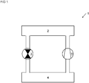
- FIG 1 schematically illustrates of a refrigerant circuit having a compressor, a condenser, an expansion valve, and an evaporator.
- FIG 2 schematically illustrates a controller of an expansion valve.
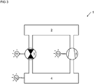
- FIG 3 schematically illustrates of a refrigerant circuit having visible indicators.
- FIG 4 schematically illustrates of a refrigerant circuit having a plurality of evaporators, expansion valves, and compressors.
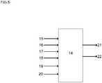
- FIG 5 illustrates a model such as a dynamic model of the at least one compressor.
Detailed description
-
FIG 1 shows a refrigerant circuit (1). The refrigerant circuit (1) can, by way of non-limiting example, be a refrigerant circuit of an air-conditioning installation or system. The refrigerant circuit (1) can, by way of another non-limiting example, also be a refrigerant circuit of a HVAC installation or system.
-
The refrigerant circuit (1) has a condenser (2). The condenser (2) provides an outlet that leads to an inlet of the at least one expansion valve (3). A conduit can connect the outlet of the condenser (2) to the inlet of the at least one expansion valve (3), thereby enabling fluid communication between the condenser (2) and the at least one expansion valve (3).
-
Refrigerant leaves the at least one expansion valve (3) via its outlet and flows toward an inlet of the at least one evaporator (4). To that end, another conduit can be provided between the outlet of the at least one expansion valve (3) and the inlet of the at least one evaporator (4).
-
The at least one evaporator (4) is in fluid communication with at least one compressor (5) via an outlet of the at least one evaporator (4) and via an inlet of the at least one compressor (5). Yet another conduit can connect the outlet of the at least one evaporator (4) to the inlet of the at least one compressor (5). The refrigerant can thus flow from the at least one evaporator (4) to the at least one compressor (5).
-
The refrigerant when leaving the at least one compressor (5) via an outlet of the at least one compressor (5) flows toward the condenser (2). To that end, still another conduit connects the outlet of the at least one compressor (5) to an inlet of the condenser (2). That conduit closes the circuit and affords refrigerant flow from the condenser (2) through the at least one expansion valve (3) and through the at least one evaporator (4) and back to the condenser (2).
-
Leakage detection and/or refrigerant leakage detection as described herein can be performed by a controller (6) of the at least one expansion valve (3). The controller (6) of the at least one expansion valve (3) advantageously comprises a microcontroller and/or a microprocessor.
-
In an embodiment, the controller (6) is separate from the at least one expansion valve (3).
-
In another embodiment, the at least one expansion valve (3) has a housing such as a metallic housing and the controller (6) is secured relative to the housing of the at least one expansion valve (3). In special embodiment, the controller (6) is arranged inside the housing of the at least one expansion valve (3).
-
In still another embodiment, the controller (6) comprises a local controller such as a controller (6) of the at least one expansion valve (3). The local controller is or comprises an inexpensive, low-power system on a chip microcontroller having integrated wireless connectivity. In a special embodiment, the chip microcontroller has a memory not exceeding one mebibyte. The controller (6) also comprises a remote controller such as a cloud computer. The local controller and the remote controller are in operative communication.
-
The controller (6) also is in operative communication with sensors (7, 8) arranged at the inlet and at the outlet of the at least one expansion valve (3). FIG 2 shows such sensors (7, 8). The sensors (7, 8) function to record signals indicative of the thermodynamic states of the refrigerant at the inlet and at the outlet of the at least one expansion valve (3). The sensors (7, 8) advantageously are sensors (7, 8) of the refrigerant circuit (1). In a special embodiment, the sensors (7, 8) are sensors (7, 8) of the at least one expansion valve (3).
-
The controller (6) can also be in operative communication with a sensor (9) arranged at the outlet of the at least one evaporator (4). The sensor (9) functions to record one or more signal indicative of the thermodynamic states of the refrigerant at the outlet of the at least one evaporator (4). The sensor (9) advantageously is a sensor (9) of the refrigerant circuit (1). In a special embodiment, the sensor (9) is a sensor (9) of the at least one evaporator (4).
-
In an embodiment, the controller (6) can also record signals indicative of the opening degree of the at least one expansion valve (3). The controller (6) can, by way of non-limiting example, record signals send to an actuator of the at least one expansion valve (3). The controller (6) can, by way of another non-limiting example, also monitor the opening degree of the at least one expansion valve (3) using a sensor within the at least one expansion valve (3). The controller (6) can, by way of yet another non-limiting example, leverage and/or analyse control signals sent to the at least one expansion valve (3) to determine the opening degree of the at least one expansion valve (3).
-
Now referring to FIG 3, a circuit (1) having a plurality of indicators (11- 13) is illustrated. The indicators (11 - 13) can indicate a fault in the refrigerant circuit (1) to maintenance personnel and/or to an operator. At least one indicator (11 - 13) can, by way of non-limiting example, indicate a leakage.
-
Now turning to FIG 4, a method and a computer program according to the instant disclosure can also be applied to a refrigerant circuit (1) having a plurality of compressors, expansion valves, and evaporators. FIG 4 illustrates a refrigerant circuit (1) having a plurality of compressors, a plurality of expansion valves and a plurality of evaporators.
-
A model (14) of the at least one compressor (5) is illustrated in FIG 5. The model (14) of FIG 5 can be a dynamic model. The model (14) receives a plurality of inputs (15 - 20) such as
- pressure and temperature at or near the outlet of the at least one evaporator (4),
- pressures and temperature at or near the outlet of the condenser (2),
- pressure and temperature at or near the inlet of the expansion valve (3),
- relative capacity,
- rated flow of refrigerant.
The model (14) of the at least one compressor (5) produces at least one output (21, 22) selected from at least one of:
-
The model (14) can be implemented by a remote controller such as a cloud computer. The remote controller is located remotely from the refrigerant circuit (1).
-
In a special embodiment, the model (14) comprises a neural network such as a trained neural network. It is envisaged that the neural network is employed to control the refrigerant circuit (1) and/or the at least one compressor (5). The neural network provides one or more output nodes for the outputs specified above. The neural network also provides a plurality of input nodes for the inputs specified above.
-
Parameters of the model (14) can, by way of non-limiting example, comprise weights of connections between neurons of the neural network. The parameters c of the model (14) can also provide activation functions of individual neurons such as sigmoid activation functions
and/or rectifier functions
-
The model (14) typically also provides topology data. The topology data can, by way of non-limiting examples, comprise information about numbers of layers of the neural network, about numbers of neurons in each layer, about connections between those layers, about biased neurons, etc.
-
Any steps of a method according to the present disclosure may be embodied in hardware, in a software module executed by a processor, in a software module executed by a processor inside a container using operating-system-level virtualization, in a cloud computing arrangement, or in a combination thereof. The software may include a firmware, a hardware driver run in the operating system, or an application program. Thus, the disclosure also relates to a computer program product for performing the operations presented herein. If implemented in software, the functions described may be stored as one or more instructions on a computer-readable medium. Some examples of storage media that may be used include random access memory (RAM), read only memory (ROM), flash memory, EPROM memory, EEPROM memory, registers, a hard disk, a removable disk, other optical disks, or any available media that can be accessed by a computer or any other IT equipment and appliance.
-
As described in detail herein, the instant disclosure teaches a method of detecting a loss of a refrigerant from a refrigerant circuit (1), the refrigerant circuit (1) comprising at least one condenser (2), at least one compressor (5), and at least one evaporator (4) having an outlet port, and at least one expansion valve (3) having an inlet port and an outlet port, the refrigerant circuit (1) also comprising a first sensor (7) for recording a thermodynamic state of the refrigerant at the inlet port of the at least one expansion valve (3) and/or a thermodynamic state of the refrigerant at or near the at least one condenser (2), and a second sensor (9) for recording a thermodynamic state of the refrigerant at the outlet port of the at least one evaporator (4), the method comprising the steps of:
- recording a first signal indicative of a thermodynamic state of the refrigerant using the first sensor (7);
- recording a second signal indicative of a thermodynamic state of the refrigerant using the second sensor (9);
- determining a first value indicative of flow through the at least one expansion valve (3) as a function of the first and second signals;
- recording a third signal, the third signal being selected from at least one of
- a signal indicative of a current compressor capacity of the at least one compressor (5);
- a signal indicative of power currently dissipated by the at least one evaporator (4);
- determining a first value indicative of flow through the at least one compressor (5) as a function of the third signal;
- determining a first ratio by relating the first value indicative of flow through the at least one compressor (5) to the first value indicative of flow through the at least one expansion valve (3); and
- if the determined first ratio exceeds one by a first threshold:
producing a first alarm signal indicative of the loss of the refrigerant.
-
According to an aspect of the present disclosure, the method comprises the steps of:
- determining using a predetermined model (14) a first value indicative of flow through the at least one expansion valve (3) as a function of the first and second signals; and
- determining using the predetermined model (14) a first value indicative of flow through the at least one compressor (5) as a function of the third signal.
-
In an embodiment, the first value indicative of flow through the at least one expansion valve (3) is a first value indicative of a flow rate through the at least one expansion valve (3). In a special embodiment, the first value indicative of flow through the at least one expansion valve (3) is a first value indicative of a mass flow rate through the at least one expansion valve (3). In an embodiment, the first value indicative of flow through the at least one compressor (5) is a first value indicative of a flow rate through the at least one compressor (5). In a special embodiment, the first value indicative of flow through the at least one compressor (5) is a first value indicative of a mass flow rate through the at least one compressor (5).
-
As also described in detail herein, the present disclosure teaches a method of detecting a loss of a refrigerant from a refrigerant circuit (1), the refrigerant circuit (1) comprising at least one condenser (2), at least one compressor (5), and at least one evaporator (4) having an outlet port, and at least one expansion valve (3) having an inlet port and an outlet port, the refrigerant circuit (1) also comprising a first sensor (7) for recording a thermodynamic state of the refrigerant at the inlet port of the at least one expansion valve (3) and/or a thermodynamic state of the refrigerant at or near the at least one condenser (2), and a second sensor (9) for recording a thermodynamic state of the refrigerant at the outlet port of the at least one evaporator (4), and a third sensor (8) for recording a thermodynamic state of the refrigerant at the outlet port of the at least one expansion valve (3), the method comprising the steps of:
- recording a first signal indicative of a thermodynamic state of the refrigerant using the first sensor (7);
- recording a second signal indicative of a thermodynamic state of the refrigerant using the second sensor (9);
- recording a fourth signal indicative of a thermodynamic state of the refrigerant using the third sensor (8);
- determining a first value indicative of flow through the at least one expansion valve (3) as a function of the first, second, and fourth signals;
- recording a third signal, the third signal being selected from at least one of
- a signal indicative of a current compressor capacity of the at least one compressor (5);
- a signal indicative of power currently dissipated by the at least one evaporator (4);
- determining a first value indicative of flow through the at least one compressor (5) as a function of the third signal;
- determining a first ratio by relating the first value indicative of flow through the at least one compressor (5) to the first value indicative of flow through the at least one expansion valve (3); and
- if the determined first ratio exceeds one by a first threshold:
producing a first alarm signal indicative of the loss of the refrigerant.
-
In an embodiment, the method comprises the steps of:
- determining using a predetermined model (14) a first value indicative of flow through the at least one expansion valve (3) as a function of the first and second signals; and
- determining using the predetermined model (14) a first value indicative of flow through the at least one compressor (5) as a function of the third signal.
-
It is envisaged that the first sensor (7) comprises a temperature sensor. It is also envisaged that the first sensor (7) comprises a pressure sensor. The first signal indicative of the thermodynamic state advantageously comprises a pressure signal of the refrigerant and/or a temperature signal of the refrigerant.
-
It is envisaged that the second sensor (9) comprises a temperature sensor. It is also envisaged that the second sensor (9) comprises a pressure sensor. The second signal indicative of the thermodynamic state advantageously comprises a pressure signal of the refrigerant and/or a temperature signal of the refrigerant.
-
It is envisaged that the third sensor (8) comprises a temperature sensor. It is also envisaged that the third sensor (8) comprises a pressure sensor. The fourth signal indicative of the thermodynamic state advantageously comprises a pressure signal of the refrigerant and/or a temperature signal of the refrigerant.
-
The present disclosure also teaches any of the aforementioned methods, the method comprising the step of:
calculating the first value indicative of flow through the at least one expansion valve (3) as a function of the first and second signals.
-
The instant disclosure further teaches any of the aforementioned methods involving a fourth signal, the method comprising the step of:
calculating the first value indicative of flow through the at least one expansion valve (3) as a function of the first, second, and fourth signals.
-
The signal indicative of power currently dissipated by the at least one evaporator (4) advantageously is a signal indicative of capacity currently dissipated by the at least one evaporator (4). The signal indicative of power currently dissipated by the at least one evaporator (4) ideally is a signal indicative of a current capacity of the at least one evaporator (4). In an embodiment, the signal indicative of power currently dissipated by the at least one evaporator (4) is a signal indicative of an amount of heat currently dissipated by the at least one evaporator (4).
-
A calculation and/or a determination of the first value indicative of flow through the at least one expansion valve (3) can involve a calculation and/or a determination of a mass flow m. The mass flow m is calculated and/or determined as a function of a current flow coefficient
kv, of a pressure at or near the inlet of the at least one expansion valve
pa , and of a density at or near the inlet of the at least one expansion valve (3)
ρa :
-
The pressure pa is advantageously recorded using the first sensor (7).
-
ψ denotes a discharge coefficient of liquids. The discharge coefficient of liquids
ψ is defined in a standard EN 60534-2-1. The same standard was published by CENELEC on 1 May 2011. The discharge coefficient
ψ can be expressed as a function of an effective pressure ratio Π
E :
-
The effective pressure ratio Π
E is the larger one of a line pressure ratio Π
L and a critical pressure ratio Π
C :
-
A relationship for the line pressure ratio Π
L reads:
wherein
pb denotes a pressure at or near the outlet of the at least one expansion valve (3). The pressure
pb is advantageously recorded using the third sensor (8) and/or using the second sensor (9).
-
If the critical pressure ratio Π
C exceeds the line pressure ratio Π
L , the mass flow
ṁ will depend on the former ratio Π
C :
FL denotes a liquid pressure recovery factor.
FL depends on the geometry of the valve such as the geometry of the at least one expansion valve (3).
pc denotes a pressure at the thermodynamic critical point and
ps denotes a pressure at saturation of an inlet temperature
Ta . An inlet temperature
Ta can ideally be recorded using the first sensor (7).
-
The mass flow
ṁ can be employed to estimate and/or to determine a capacity Q
evap of the at least one evaporator (4),
wherein
- h 1 denotes the enthalpy at or near the outlet of the at least one evaporator (4),
- h 5 denotes the enthalpy at or near the outlet of the condenser (2),
- h 6 denotes the enthalpy at or near the inlet of the at least one expansion valve (3), and
- h 8 denotes the enthalpy at or near the inlet of the at least one evaporator (4).
-
These enthalpies generally depend on pressure
p and on temperature
T:
-
For conditions that correspond to saturation characteristics, these enthalpies are fully determined by a saturation pressure
p s:
-
The mass flow through the compressor
ṁcomp also determines the current capacity of the at least one compressor
Q̇comp :
-
Likewise, the mass flow through the expansion valve
ṁvalve determines the current capacity of the at least one compressor
Q̇valve :
-
It is envisaged that the first value of maximum available capacity of the refrigerant circuit (1) is a first value of maximum available cooling power of the refrigerant circuit (1).
-
The present disclosure still teaches any of the aforementioned methods, the method comprising the step of:
calculating and/or determining a first value of maximum available cooling power of the refrigerant circuit (1) as a function of the first and second signals.
-
The instant disclosure still further teaches any of the aforementioned methods involving a fourth signal, the method comprising the step of:
calculating and/or determining a first value of maximum available cooling power of the refrigerant circuit (1) as a function of the first, second, and fourth signals.
-
In an embodiment, a signal indicative of a current compressor capacity of the at least one compressor (5) comprises a signal indicative of an instantaneous compressor capacity of the at least one compressor (5). It is envisaged that a signal indicative of a current compressor capacity of the at least one compressor (5) is a signal indicative of an instantaneous compressor capacity of the at least one compressor (5).
-
The instant disclosure yet further teaches any of the aforementioned methods, the method comprising the step of:
calculating a first value indicative of flow through the at least one compressor (5) as a function of the third signal.
-
The instant disclosure also teaches any of the aforementioned methods, the method comprising the step of:
if the determined first ratio exceeds one augmented by the first threshold:
producing the first alarm signal indicative of the loss of the refrigerant.
-
The instant disclosure further teaches any of the aforementioned methods, the method comprising the step of:
if the determined first ratio exceeds unity augmented by the first threshold:
producing the first alarm signal indicative of the loss of the refrigerant.
-
In an embodiment, the first threshold is less than 0.5. That is, if the determined first ratio exceeds 1.5, the first alarm signal indicative of the loss of the refrigerant will be produced. In a special embodiment, the first threshold is less than 0.2. That is, if the determined first ratio exceeds 1.2, the first alarm signal indicative of the loss of the refrigerant will be produced. In yet another special embodiment, the first threshold is less than 0.1. That is, if the determined first ratio exceeds 1.1, the first alarm signal indicative of the loss of the refrigerant will be produced. Low first thresholds reduce likelihoods of false negatives.
-
The present disclosure also teaches any of the aforementioned methods, the method comprising the step of:
calculating and/or determining the first ratio by dividing the first value indicative of flow through the at least one compressor (5) by the first value indicative of flow through the at least one expansion valve (3).
-
The first sensor (7) is advantageously different from the third sensor (8). The third sensor (8) is ideally different from the second sensor (9). The second sensor (9) is advantageously different from the first sensor (7).
-
It is envisaged that the method of detecting a loss of a refrigerant from a refrigerant circuit (1) is a method of detecting loss of a refrigerant from a refrigerant circuit (1). It is also envisaged that the method of detecting a loss of a refrigerant from a refrigerant circuit (1) is a method of detecting loss of refrigerant from a refrigerant circuit (1). It is still envisaged that the method of detecting a loss of a refrigerant from a refrigerant circuit (1) is a method of mitigating a loss of a refrigerant from a refrigerant circuit (1). It is still further envisaged that the method of detecting a loss of a refrigerant from a refrigerant circuit (1) is a method of mitigating loss of a refrigerant from a refrigerant circuit (1).
-
It is yet further envisaged that the method of detecting a loss of a refrigerant from a refrigerant circuit (1) is a method of mitigating loss of refrigerant from a refrigerant circuit (1).
-
The present disclosure also teaches any of the aforementioned methods, wherein the refrigerant circuit (1) comprises a condenser (2). The condenser (2) advantageously is in fluid communication with the at least one expansion valve (3). The condenser (2) advantageously is in fluid communication with the at least one compressor (5), too.
-
The instant disclosure still teaches any of the aforementioned methods, wherein the at least one expansion valve (3) has a characteristic curve, the method comprising the step of:
using the characteristic curve of the at least one expansion valve (3) to determine the first value indicative of flow through the at least one expansion valve (3) as a function of the first and second signals.
-
The present disclosure still further teaches any of the aforementioned methods involving a fourth signal, wherein the at least one expansion valve (3) has a characteristic curve, the method comprising the step of:
using the characteristic curve of the at least one expansion valve (3) to determine the first value indicative of flow through the at least one expansion valve (3) as a function of the first, second, and fourth signals.
-
The instant disclosure yet further teaches any of the aforementioned methods, wherein the at least one expansion valve (3) has a characteristic curve, the method comprising the step of:
using the characteristic curve of the at least one expansion valve (3) to calculate the first value indicative of flow through the at least one expansion valve (3) as a function of the first and second signals.
-
The instant disclosure also teaches any of the aforementioned methods involving a fourth signal, wherein the at least one expansion valve (3) has a characteristic curve, the method comprising the step of:
using the characteristic curve of the at least one expansion valve (3) to calculate the first value indicative of flow through the at least one expansion valve (3) as a function of the first, second, and fourth signals.
-
The present disclosure still teaches any of the aforementioned methods, wherein the at least one expansion valve (3) has a characteristic curve, the method comprising the step of:
using the characteristic curve of the at least one expansion valve (3) to calculate and/or to determine a first value of maximum available power as a function of the first and second signals.
-
The instant disclosure still further teaches any of the aforementioned methods involving a fourth signal, wherein the at least one expansion valve (3) has a characteristic curve, the method comprising the step of:
using the characteristic curve of the at least one expansion valve (3) to calculate and/or to determine a first value of maximum available power as a function of the first, second, and fourth signals.
-
According to an aspect of the present disclosure, the characteristic curve of the at least one expansion valve (3) relates capacity to superheat. According to a special aspect of the instant disclosure, the characteristic curve of the at least one expansion valve (3) relates capacity to a temperature drop across the at least one expansion valve (3). According to another special aspect of the present disclosure, the characteristic curve of the at least one expansion valve (3) relates an amount of power to a temperature drop across the at least one expansion valve (3).
-
The present disclosure still teaches any of the aforementioned methods, the method comprising the steps of:
- receiving a demand signal, the demand signal comprising a request directed to the at least one compressor (5) to operate at an indicated compressor capacity; and
- producing the signal indicative of the current compressor capacity of the at least one compressor (5) as a function of the demand signal.
-
The instant disclosure also teaches any of the aforementioned methods, the method comprising the steps of:
- receiving a demand signal, the demand signal comprising a request directed to the at least one compressor (5) to operate at an indicated compressor capacity; and
- producing the signal indicative of the current compressor capacity of the at least one compressor (5) as a function of the demand signal.
-
It is envisaged that the demand signal causes the at least one compressor (5) to operate at the indicated compressor capacity. It is also envisaged that the demand signal causes the at least one compressor (5) to operate at the indicated current compressor capacity.
-
The present disclosure also teaches any of the aforementioned methods, wherein the refrigerant circuit (1) comprises a fourth sensor associated with the at least one compressor (5), the method comprising the step of:
recording the signal indicative of a current compressor capacity of the at least one compressor (5) from the fourth sensor associated with the at least one compressor (5).
-
The instant disclosure further teaches any of the aforementioned methods, wherein the refrigerant circuit (1) comprises a fourth sensor associated with the at least one compressor (5), the method comprising the step of:
- recording the signal indicative of a current compressor capacity of the at least one compressor (5) from the fourth sensor associated with the at least one compressor (5);
- producing an estimate of current compressor capacity of the at least one compressor (5) as a function of the signal indicative of a current compressor capacity of the at least one compressor (5) and as a function of a characteristic curve of the at least one compressor (5); and
- determining the first value indicative of flow through the at least one compressor (5) as a function of the estimate of current compressor capacity.
-
The present disclosure still further teaches any of the aforementioned methods, wherein the refrigerant circuit (1) comprises a fourth sensor associated with the at least one compressor (5), the method comprising the step of:
- recording the signal indicative of a current compressor capacity of the at least one compressor (5) from the fourth sensor associated with the at least one compressor (5);
- producing an measure of current compressor capacity of the at least one compressor (5) as a function of the signal indicative of a current compressor capacity of the at least one compressor (5) and as a function of a characteristic curve of the at least one compressor (5); and
- determining the first value indicative of flow through the at least one compressor (5) as a function of the measure of current compressor capacity.
-
It is envisaged that the fourth sensor comprises a speed sensor. It is also envisaged that the fourth sensor comprises a speed sensor.
-
In an embodiment, the fourth sensor connects to the at least one compressor (5). More specifically, the fourth sensor can electrically connect to the at least one compressor (5).
-
In a special embodiment, the at least one compressor (5) comprises the fourth sensor. It is envisaged that the at least one compressor (5) comprises a housing such as a metallic housing and that the fourth sensor is secured relative to the housing of the at least one compressor (5). It is also envisaged that the at least one compressor (5) comprises a housing such as a metallic housing and that the fourth sensor is mounted to the housing of the at least one compressor (5).
-
The fourth sensor is advantageously different from the first sensor (7). The fourth sensor is ideally different from the third sensor (8). The fourth sensor is advantageously different from the second sensor (9). The fourth sensor is ideally different from the fifth sensor. The fourth sensor is preferably different from the sixth sensor (10).
-
The instant disclosure further teaches any of the aforementioned methods, the method comprising the step of:
recording the signal indicative of a current compressor capacity of the at least one compressor (5) from a speed signal transmitted to the at least one compressor (5).
-
In an embodiment, the speed signal transmitted to the at least one compressor (5) comprises a pulse-width modulated signal. In a special embodiment, the speed signal transmitted to the at least one compressor (5) is a pulse-width modulated signal. In an alternate embodiment, the speed signal transmitted to the at least one compressor (5) comprises a signal originating from an inverter. In a special embodiment, the speed signal transmitted to the at least one compressor (5) is a signal originating from an inverter.
-
The present disclosure further teaches any of the aforementioned methods, the method comprising the step of:
recording the signal indicative of a current compressor capacity of the at least one compressor (5) from a speed signal associated with the at least one compressor (5).
-
In an embodiment, the speed signal associated with the at least one compressor (5) comprises a pulse-width modulated signal. In a special embodiment, the speed signal associated with the at least one compressor (5) is a pulse-width modulated signal. In an alternate embodiment, the speed signal associated with the at least one compressor (5) comprises a signal originating from an inverter. In a special embodiment, the speed signal associated with the at least one compressor (5) is a signal originating from an inverter.
-
In a special embodiment, the refrigerant circuit (1) comprises a pulse-width modulation circuit. It is envisaged that the refrigerant circuit (1) comprises a housing such as a metallic housing and that the pulse-width modulation circuit is secured relative to the housing of the refrigerant circuit (1). It is also envisaged that the refrigerant circuit (1) comprises a housing such as a metallic housing and that the pulse-width modulation circuit is mounted to the housing of the refrigerant circuit (1). The pulse-width modulation circuit advantageously connects to the at least one compressor (5).
-
In another special embodiment, the refrigerant circuit (1) comprises the inverter. It is envisaged that the refrigerant circuit (1) comprises a housing such as a metallic housing and that the inverter is secured relative to the housing of the refrigerant circuit (1). It is also envisaged that the refrigerant circuit (1) comprises a housing such as a metallic housing and that the inverter is mounted to the housing of the refrigerant circuit (1). The inverter advantageously connects to the at least one compressor (5).
-
The present disclosure also teaches any of the aforementioned methods, wherein the refrigerant circuit (1) comprises a fifth sensor associated with the at least one compressor (5), the method comprising the step of:
recording the signal indicative of a current compressor capacity of the at least one compressor (5) from the fifth sensor associated with the at least one compressor (5).
-
The instant disclosure further teaches any of the aforementioned methods, wherein the refrigerant circuit (1) comprises a fifth sensor associated with the at least one compressor (5), the method comprising the step of:
- recording the signal indicative of a current compressor capacity of the at least one compressor (5) from the fifth sensor associated with the at least one compressor (5);
- producing an estimate of current compressor capacity of the at least one compressor (5) as a function of the signal indicative of a current compressor capacity of the at least one compressor (5) and as a function of a characteristic curve of the at least one compressor (5); and
- determining the first value indicative of flow through the at least one compressor (5) as a function of the estimate of current compressor capacity.
-
The present disclosure still further teaches any of the aforementioned methods, wherein the refrigerant circuit (1) comprises a fifth sensor associated with the at least one compressor (5), the method comprising the step of:
- recording the signal indicative of a current compressor capacity of the at least one compressor (5) from the fifth sensor associated with the at least one compressor (5);
- producing a measure of current compressor capacity of the at least one compressor (5) as a function of the signal indicative of a current compressor capacity of the at least one compressor (5) and as a function of a characteristic curve of the at least one compressor (5); and
- determining the first value indicative of flow through the at least one compressor (5) as a function of the measure of current compressor capacity.
-
The present disclosure also teaches any of the aforementioned methods, wherein the refrigerant circuit (1) comprises a fifth sensor associated with the refrigerant circuit (1), the method comprising the step of:
recording the signal indicative of a current compressor capacity of the at least one compressor (5) from the fifth sensor associated with the refrigerant circuit (1).
-
The instant disclosure further teaches any of the aforementioned methods, wherein the refrigerant circuit (1) comprises a fifth sensor associated with the refrigerant circuit (1), the method comprising the step of:
- recording the signal indicative of a current compressor capacity of the at least one compressor (5) from the fifth sensor associated with the refrigerant circuit (1);
- producing an estimate of current compressor capacity of the at least one compressor (5) as a function of the signal indicative of a current compressor capacity of the at least one compressor (5) and as a function of a characteristic curve of the at least one compressor (5); and
- determining the first value indicative of flow through the at least one compressor (5) as a function of the estimate of current compressor capacity.
-
The present disclosure still further teaches any of the aforementioned methods, wherein the refrigerant circuit (1) comprises a fifth sensor associated with the refrigerant circuit (1), the method comprising the step of:
- recording the signal indicative of a current compressor capacity of the at least one compressor (5) from the fifth sensor associated with the refrigerant circuit (1);
- producing a measure of current compressor capacity of the at least one compressor (5) as a function of the signal indicative of a current compressor capacity of the at least one compressor (5) and as a function of a characteristic curve of the at least one compressor (5); and
- determining the first value indicative of flow through the at least one compressor (5) as a function of the measure of current compressor capacity.
-
It is envisaged that the fifth sensor is a mass flow sensor. It is also envisaged that the fifth sensor comprises a mass flow sensor.
-
In an embodiment, the fifth sensor connects to a controller such as a controller of the refrigerant circuit (1). More specifically, the fifth sensor electrically connects to a controller such as a controller of the refrigerant circuit (1).
-
In a special embodiment, the at least one compressor (5) comprises the fifth sensor. It is envisaged that the at least one compressor (5) comprises a housing such as a metallic housing and that the fifth sensor is secured relative to the housing of the at least one compressor (5). It is also envisaged that the at least one compressor (5) comprises a housing such as a metallic housing and that the fifth sensor is mounted to the housing of the at least one compressor (5).
-
In another embodiment, the fifth sensor connects to the refrigerant circuit (1). More specifically, the fifth sensor can electrically connect to the refrigerant circuit (1).
-
The fifth sensor is advantageously different from the first sensor (7). The fifth sensor is ideally different from the third sensor (8). The fifth sensor is advantageously different from the second sensor (9). The fifth sensor is preferably different from the fourth sensor. The fifth sensor is advantageously different from the sixth sensor (10).
-
The present disclosure also teaches any of the aforementioned methods, wherein the refrigerant circuit (1) comprises a sixth sensor (10) associated with the at least one evaporator (4), the method comprising the step of:
recording the signal indicative of power currently dissipated by the at least one evaporator (4) using the sixth sensor (10).
-
It is envisaged that the sixth sensor (10) comprises a temperature sensor. It is also envisaged that the sixth sensor (10) comprises a pressure sensor. It is still envisaged that the sixth sensor (10) comprises a meter such as a heat meter and/or a cooling meter.
-
In an embodiment, the sixth sensor (10) connects to the at least one evaporator (4). More specifically, the sixth sensor (10) can mechanically connect to the at least one evaporator (4). It is envisaged that the at least one evaporator (4) comprises a housing such as a metallic housing and that the sixth sensor (10) is secured relative to the housing of the at least one evaporator (4). It is still envisaged that the at least one evaporator (4) comprises a housing such as a metallic housing and that the sixth sensor (10) is mounted to the housing of the at least one evaporator (4).
-
The sixth sensor (10) is advantageously different from the first sensor (7). The sixth sensor (10) is ideally different from the third sensor (8). The sixth sensor (10) is advantageously different from the second sensor (9). The sixth sensor (10) is ideally different from the fourth sensor associated with or of the at least one compressor (5).
-
The instant disclosure also teaches any of the aforementioned methods, wherein the at least one expansion valve (3) comprises a valve member, the valve member being movable between an open position which allows refrigerant flow through the at least one expansion valve (3) and a closed position which obturates refrigerant flow through the at least one expansion valve (3), the method comprising the steps of:
- recording from the at least one expansion valve (3) a position signal indicative of the position of the valve member; and
- determining the first value indicative of flow through the at least one expansion valve (3) as a function of the first and second signals and as a function of the position signal.
-
The present disclosure still teaches any of the aforementioned methods involving a fourth signal, wherein the at least one expansion valve (3) comprises a valve member, the valve member being movable between an open position which allows refrigerant flow through the at least one expansion valve (3) and a closed position which obturates refrigerant flow through the at least one expansion valve (3), the method comprising the steps of:
- recording from the at least one expansion valve (3) a position signal indicative of the position of the valve member; and
- determining the first value indicative of flow through the at least one expansion valve (3) as a function of the first, second, and fourth signals and as a function of the position signal.
-
The instant disclosure still further teaches any of the aforementioned methods, wherein the at least one expansion valve (3) comprises a valve member, the valve member being movable between an open position which allows refrigerant flow through the at least one expansion valve (3) and a closed position which obturates refrigerant flow through the at least one expansion valve (3), the method comprising the steps of:
- recording from the at least one expansion valve (3) a position signal indicative of the position of the valve member; and
- calculating the first value indicative of flow through the at least one expansion valve (3) as a function of the first and second signals and as a function of the position signal.
-
The present disclosure also teaches any of the aforementioned methods involving a fourth signal, wherein the at least one expansion valve (3) comprises a valve member, the valve member being movable between an open position which allows refrigerant flow through the at least one expansion valve (3) and a closed position which obturates refrigerant flow through the at least one expansion valve (3), the method comprising the steps of:
- recording from the at least one expansion valve (3) a position signal indicative of the position of the valve member; and
- calculating the first value indicative of flow through the at least one expansion valve (3) as a function of the first, second, and fourth signals and as a function of the position signal.
-
The instant disclosure still teaches any of the aforementioned methods, wherein the at least one expansion valve (3) comprises a valve member, the valve member being movable between an open position which allows refrigerant flow through the at least one expansion valve (3) and a closed position which obturates refrigerant flow through the at least one expansion valve (3), the method comprising the steps of:
- connecting to the at least one expansion valve (3);
- receiving from the at least one expansion valve (3) a position signal indicative of the position of the valve member; and
- calculating and/or determining the first value indicative of flow through the at least one expansion valve (3) as a function of the first and second signals and as a function of the position signal.
-
The present disclosure still further teaches any of the aforementioned methods involving a fourth signal, wherein the at least one expansion valve (3) comprises a valve member, the valve member being movable between an open position which allows refrigerant flow through the at least one expansion valve (3) and a closed position which obturates refrigerant flow through the at least one expansion valve (3), the method comprising the steps of:
- connecting to the at least one expansion valve (3);
- receiving from the at least one expansion valve (3) a position signal indicative of the position of the valve member; and
- calculating and/or determining the first value indicative of flow through the at least one expansion valve (3) as a function of the first, second, and fourth signals and as a function of the position signal.
-
The instant disclosure yet further teaches any of the aforementioned methods, wherein the at least one expansion valve (3) comprises a valve member, the valve member being movable between an open position which allows refrigerant flow through the at least one expansion valve (3) and a closed position which obturates refrigerant flow through the at least one expansion valve (3), the method comprising the steps of:
- connecting to the at least one expansion valve (3);
- receiving from the at least one expansion valve (3) a position signal indicative of the position of the valve member;
- producing a position measure from the position signal; and
- calculating and/or determining the first value indicative of flow through the at least one expansion valve (3) as a function of the first and second signals and as a function of the position measure.
-
The present disclosure also teaches any of the aforementioned methods involving a fourth signal, wherein the at least one expansion valve (3) comprises a valve member, the valve member being movable between an open position which allows refrigerant flow through the at least one expansion valve (3) and a closed position which obturates refrigerant flow through the at least one expansion valve (3), the method comprising the steps of:
- connecting to the at least one expansion valve (3);
- receiving from the at least one expansion valve (3) a position signal indicative of the position of the valve member;
- producing a position measure from the position signal; and
- calculating and/or determining the first value indicative of flow through the at least one expansion valve (3) as a function of the first, second, and fourth signals and as a function of the position measure.
-
In an embodiment, the position measure is produced from the position signal using analog-to-digital conversion. In another embodiment, the position measure is produced from the position signal using delta-sigma modulation. In still another embodiment, the position measure is produced from the position signal using analog-to-digital conversion and delta-sigma modulation.
-
According to an aspect of the present disclosure, the above methods involving a position signal comprise the steps of:
- connecting to the at least one expansion valve (3) via a communication bus; and
- receiving from the at least one expansion valve (3) and via the communication bus a position signal indicative of the position of the valve member.
-
According to a special aspect of the present disclosure, the above methods involving a position signal comprise the steps of:
- connecting to the at least one expansion valve (3) using a communication bus protocol; and
- receiving from the at least one expansion valve (3) a position signal indicative of the position of the valve member using the communication bus protocol.
-
In an embodiment, the at least one expansion valve (3) comprises a valve member, the valve member being movable between an open position which enables flow of refrigerant through the at least one expansion valve (3) and a closed position which obturates flow of refrigerant through the at least one expansion valve (3).
-
The instant disclosure also teaches any of the aforementioned methods involving a position signal and a characteristic curve of at least one expansion valve (3), the method comprising the steps of:
- recording from the at least one expansion valve (3) the position signal indicative of the position of the valve member; and
- using the characteristic curve of the at least one expansion valve (3) to determine the first value indicative of flow through the at least one expansion valve (3) as a function of the first and second signals and as a function of the position signal.
-
The present disclosure still teaches any of the aforementioned methods involving a fourth signal and a position signal and a characteristic curve of at least one expansion valve (3), the method comprising the steps of:
- recording from the at least one expansion valve (3) the position signal indicative of the position of the valve member; and
- using the characteristic curve of the at least one expansion valve (3) to determine the first value indicative of flow through the at least one expansion valve (3) as a function of the first, second, and fourth signals and as a function of the position signal.
-
The instant disclosure still further teaches any of the aforementioned methods involving a position signal and a characteristic curve of at least one expansion valve (3), the method comprising the steps of:
- recording from the at least one expansion valve (3) the position signal indicative of the position of the valve member; and
- using the characteristic curve of the at least one expansion valve (3) to calculate the first value indicative of flow through the at least one expansion valve (3) as a function of the first and second signals and as a function of the position signal.
-
The present disclosure yet further teaches any of the aforementioned methods involving fourth signal and a position signal and a characteristic curve of at least one expansion valve (3), the method comprising the steps of:
- recording from the at least one expansion valve (3) the position signal indicative of the position of the valve member; and
- using the characteristic curve of the at least one expansion valve (3) to calculate the first value indicative of flow through the at least one expansion valve (3) as a function of the first, second, and fourth signals and as a function of the position signal.
-
The instant disclosure still teaches any of the aforementioned methods involving a position signal and a characteristic curve of at least one expansion valve (3), the method comprising the steps of:
- connecting to the at least one expansion valve (3);
- receiving from the at least one expansion valve (3) the position signal indicative of the position of the valve member;
- producing the position measure from the position signal; and
- using the characteristic curve of the at least one expansion valve (3) to calculate the first value indicative of flow through the at least one expansion valve (3) as a function of the first and second signals and as a function of the position measure.
-
The present disclosure still further teaches any of the aforementioned methods involving a fourth signal and a position signal and a characteristic curve of at least one expansion valve (3), the method comprising the steps of:
- connecting to the at least one expansion valve (3);
- receiving from the at least one expansion valve (3) the position signal indicative of the position of the valve member;
- producing the position measure from the position signal; and
- using the characteristic curve of the at least one expansion valve (3) to calculate the first value indicative of flow through the at least one expansion valve (3) as a function of the first, second, and fourth signals and as a function of the position measure.
-
The present disclosure also teaches any of the aforementioned methods, wherein the refrigerant circuit (1) comprises a visible indicator (11 - 13), the method comprising the step of:
if the determined first ratio exceeds one by the first threshold:
activating the visible indicator (11 - 13).
-
The instant disclosure also teaches any of the aforementioned methods, the method comprising the step of:
if the determined first ratio exceeds one augmented by the first threshold:
activating the visible indicator (11 - 13).
-
The instant disclosure still teaches any of the aforementioned methods, the method comprising the step of:
if the determined first ratio exceeds unity augmented by the first threshold:
activating the visible indicator (11 - 13).
-
The visible indicator (11 - 13) advantageously comprises a light-emitting diode and/or a display. In a special embodiment, the visible indicator (11 - 13) comprises a diode emitting red light. In another special embodiment, the visible indicator (11 - 13) is a diode emitting red light.
-
It is envisaged that the refrigerant circuit (1) comprises a housing such as a metallic housing and that the visible indicator (11 - 13) is secured relative to the housing of the refrigerant circuit (1). It is also envisaged that the refrigerant circuit (1) comprises a housing such as a metallic housing and that the visible indicator (11 - 13) is mounted to the housing of the refrigerant circuit (1).
-
It is envisaged that the at least one expansion valve (3) comprises a housing such as a metallic housing and that the visible indicator (11) is secured relative to the housing of the at least one expansion valve (3). It is also envisaged that the at least one expansion valve (3) comprises a housing such as a metallic housing and that the visible indicator (11) is mounted to the housing of the at least one expansion valve (3).
-
It is envisaged that the at least one evaporator (4) comprises a housing such as a metallic housing and that the visible indicator (12) is secured relative to the housing of the at least one evaporator (4). It is also envisaged that the at least one evaporator (4) comprises a housing such as a metallic housing and that the visible indicator (12) is mounted to the housing of the at least one evaporator (4).
-
It is envisaged that the at least one compressor (5) comprises a housing such as a metallic housing and that the visible indicator (13) is secured relative to the housing of the at least one compressor (5). It is also envisaged that the at least one compressor (5) comprises a housing such as a metallic housing and that the visible indicator (13) is mounted to the housing of the at least one compressor (5).
-
The present disclosure also teaches any of the aforementioned methods, the method comprising the steps of:
- after recording the third signal, recording a fifth signal, the fifth signal being selected from at least one of
- a signal indicative of a current compressor capacity of the at least one compressor (5);
- a signal indicative of power currently dissipated by the at least one evaporator (4);
- determining a second value indicative of flow through the at least one compressor (5) as a function of the fifth signal;
- determining a second ratio by relating the second value indicative of flow through the at least one compressor (5) to the first value indicative of flow through the at least one expansion valve (3);
- determining a difference between the second ratio and the first ratio; and
- if the difference between the second ratio and the first ratio exceeds a second threshold:
producing a second alarm signal indicative of the loss of the refrigerant.
-
In an embodiment, the second value indicative of flow through the at least one compressor (5) is a second value indicative of a flow rate through the at least one compressor (5). In a special embodiment, the second value indicative of flow through the at least one compressor (5) is a second value indicative of a mass flow rate through the at least one compressor (5).
-
The instant disclosure also teaches any of the aforementioned methods involving a fifth signal, the method comprising the step of:
calculating the second ratio by relating the second value indicative of flow through the at least one compressor (5) to the first value indicative of flow through the at least one expansion valve (3).
-
The instant disclosure still teaches any of the aforementioned methods involving a fifth signal, the method comprising the step of:
calculating and/or determining the second ratio by dividing the second value indicative of flow through the at least one compressor (5) by the first value indicative of flow through the at least one expansion valve (3).
-
The instant disclosure yet further teaches any of the aforementioned methods involving a fifth signal, the method comprising the step of:
calculating the difference between the second ratio and the first ratio.
-
According to an aspect of the present disclosure, the first alarm signal indicative of the loss of the refrigerant is the same as the second alarm signal indicative of the loss of the refrigerant.
-
It is envisaged that the second threshold is a second predetermined threshold.
-
The instant disclosure also teaches any of the aforementioned methods, the method comprising the steps of:
- after recording the first signal, recording a sixth signal indicative of a thermodynamic state of the refrigerant using the first sensor (7);
- after recording the second signal, recording a seventh signal indicative of a thermodynamic state of the refrigerant using the second sensor (9);
- determining a second value indicative of flow through the at least one expansion valve (3) as a function of the sixth and seventh signals;
- after recording the third signal, recording an eighth signal, the eighth signal being selected from at least one of
- a signal indicative of a current compressor capacity of the at least one compressor (5);
- a signal indicative of power currently dissipated by the at least one evaporator (4);
- determining a third value indicative of flow through the at least one compressor (5) as a function of the eighth signal;
- determining a third ratio by relating the third value indicative of flow through the at least one compressor (5) to the second value indicative of flow through the at least one expansion valve (3);
- determining a difference between the third ratio and the first ratio; and
- if the difference between the third ratio and the first ratio exceeds a third threshold:
producing a third alarm signal indicative of the loss of the refrigerant.
-
In an embodiment, the second value indicative of flow through the at least one expansion valve (3) is a second value indicative of a flow rate through the at least one expansion valve (3). In a special embodiment, the second value indicative of flow through the at least one expansion valve (3) is a second value indicative of a mass flow rate through the at least one expansion valve (3).
-
In an embodiment, the third value indicative of flow through the at least one compressor (5) is a third value indicative of a flow rate through the at least one compressor (5). In a special embodiment, the third value indicative of flow through the at least one compressor (5) is a third value indicative of a mass flow rate through the at least one compressor (5).
-
The present disclosure also teaches any of the aforementioned methods involving a fourth signal, the method comprising the steps of:
- after recording the first signal, recording a sixth signal indicative of a thermodynamic state of the refrigerant using the first sensor (7);
- after recording the second signal, recording a seventh signal indicative of a thermodynamic state of the refrigerant using the second sensor (9);
- after recording the fourth signal, recording a ninth signal indicative of a thermodynamic state of the refrigerant using the third sensor (8);
- determining a second value indicative of flow through the at least one expansion valve (3) as a function of the sixth, seventh, and ninth signals;
- after recording the third signal, recording an eighth signal, the eighth signal being selected from at least one of
- a signal indicative of a current compressor capacity of the at least one compressor (5);
- a signal indicative of power currently dissipated by the at least one evaporator (4);
- determining a third value indicative of flow through the at least one compressor (5) as a function of the eighth signal;
- determining a third ratio by relating the third value indicative of flow through the at least one compressor (5) to the second value indicative of flow through the at least one expansion valve (3);
- determining a difference between the third ratio and the first ratio; and
- if the difference between the third ratio and the first ratio exceeds a third threshold:
producing a third alarm signal indicative of the loss of the refrigerant.
-
It is envisaged that the second value indicative of flow through the at least one expansion valve (3) is a second value of maximum available cooling power of the refrigerant circuit (1).
-
The instant disclosure also teaches any of the aforementioned methods involving a sixth signal, the method comprising the step of:
calculating the third ratio by relating the third value indicative of flow through the at least one compressor (5) to the second value indicative of flow through the at least one expansion valve (3).
-
The instant disclosure still teaches any of the aforementioned methods involving a sixth signal, the method comprising the step of:
calculating and/or determining the third ratio by dividing the third value indicative of flow through the at least one compressor (5) by the second value indicative of flow through the at least one expansion valve (3).
-
The instant disclosure yet further teaches any of the aforementioned methods involving a sixth signal, the method comprising the step of:
calculating the difference between the third ratio and the first ratio.
-
It is envisaged that the third threshold is a third predetermined threshold.
-
According to an aspect of the present disclosure, the third alarm signal indicative of the loss of the refrigerant is the same as the first alarm signal indicative of the loss of the refrigerant. It is also envisaged that the third alarm signal indicative of the loss of the refrigerant is the same as the second alarm signal indicative of the loss of the refrigerant.
-
The instant disclosure also teaches any of the aforementioned methods, wherein evaporator (4) comprises an inlet port and wherein the refrigerant circuit (1) comprises a conduit connecting the outlet port of the at least one expansion valve (3) to the inlet port of the at least one evaporator (4), wherein a flow of refrigerant through the conduit causes a decrease in pressure of the refrigerant, the method comprising the step of:
determining the first value indicative of flow through the at least one expansion valve (3) as a function of the first and second signals and as a function of the decrease in pressure of the refrigerant.
-
The present disclosure further teaches any of the aforementioned methods involving a fourth signal, wherein evaporator (4) comprises an inlet port and wherein the refrigerant circuit (1) comprises a conduit connecting the outlet port of the at least one expansion valve (3) to the inlet port of the at least one evaporator (4), wherein a flow of refrigerant through the conduit causes a decrease in pressure of the refrigerant, the method comprising the step of:
determining the first value indicative of flow through the at least one expansion valve (3) as a function of the first, second, and fourth signals and as a function of the decrease in pressure of the refrigerant.
-
The instant disclosure still further teaches any of the aforementioned methods involving a decrease in pressure of the refrigerant, the method comprising the step of:
calculating the first value indicative of flow through the at least one expansion valve (3) as a function of the first and second signals and as a function of the decrease in pressure of the refrigerant.
-
The present disclosure also teaches any of the aforementioned methods involving a fourth signal and a decrease in pressure of the refrigerant, the method comprising the step of:
calculating the first value indicative of flow through the at least one expansion valve (3) as a function of the first, second, and fourth signals and as a function of the decrease in pressure of the refrigerant.
-
The present disclosure still teaches any of the aforementioned methods involving a sixth signal and involving a decrease in pressure of the refrigerant, the method comprising the step of:
calculating and/or determining the second value indicative of flow through the at least one expansion valve (3) as a function of the sixth and seventh signals and as a function of the decrease in pressure of the refrigerant.
-
The instant disclosure still further teaches any of the aforementioned methods involving a fourth signal and a sixth signal and involving a decrease in pressure of the refrigerant and a ninth signal, the method comprising the step of:
calculating and/or determining the second value indicative of flow through the at least one expansion valve (3) as a function of the sixth, seventh, and ninth signals and as a function of the decrease in pressure of the refrigerant.
-
In an embodiment, the conduit has a decrease in pressure of the refrigerant. The decrease in pressure of the refrigerant is preferably known at design stage. That is, the decrease in pressure of the refrigerant is a characteristic of the conduit and/or of the refrigerant circuit (1).
-
The present disclosure also teaches a computer program comprising instructions which, when the program is executed by a computer, cause the computer to carry out the steps of any of the aforementioned methods.
-
The instant disclosure also teaches a computer program product comprising instructions which, when the computer program product is executed by a computer, cause the computer to carry out the steps of any of the aforementioned methods.
-
The instant disclosure still teaches a computer program comprising instructions which, when the program is executed by a controller (6) of a refrigerant circuit (1), cause the controller (6) to carry out the steps of any of the aforementioned methods.
-
The instant disclosure still teaches a computer program product comprising instructions which, when the program product is executed by a controller (6) of a refrigerant circuit (1), cause the controller (6) to carry out the steps of any of the aforementioned methods.
-
The instant disclosure still further teaches a computer program comprising instructions which, when the program is executed by a controller (6) of a refrigerant circuit (1), the controller (6) being in operative communication with the first sensor (7), with the third sensor (8), with the second sensor (9), and with at least one of the at least one evaporator (4) or the at least one compressor (5), cause the controller (6) to carry out the steps of any of the aforementioned methods.
-
The instant disclosure still further teaches a computer program product comprising instructions which, when the computer program product is executed by a controller (6) of a refrigerant circuit (1), the controller (6) being in operative communication with the first sensor (7), with the third sensor (8), with the second sensor (9), and with at least one of the at least one evaporator (4) or the at least one compressor (5), cause the controller (6) to carry out the steps of any of the aforementioned methods.
-
The present disclosure also teaches a computer-readable medium having stored thereon any one of the aforementioned computer programs.
-
The present disclosure also teaches a computer-readable medium having stored thereon any one of the aforementioned computer program products.
-
It should be understood that the foregoing relates only to certain embodiments of the disclosure and that numerous changes can be made therein without departing from the scope of the disclosure as defined by the following claims. It should also be understood that the disclosure is not restricted to the illustrated embodiments and that various modifications can be made within the scope of the claims.
Reference numerals
-
- 1
- refrigerant circuit
- 2
- condenser
- 3
- expansion valve
- 4
- evaporator
- 5
- compressor
- 6
- controller
- 7 - 10
- sensors
- 11 - 13
- visible indicators
- 14
- model
- 15 - 20
- model inputs
- 21, 22
- model outputs