EP2812640B1 - Method for detection of loss of refrigerant - Google Patents
Method for detection of loss of refrigerant Download PDFInfo
- Publication number
- EP2812640B1 EP2812640B1 EP13706332.7A EP13706332A EP2812640B1 EP 2812640 B1 EP2812640 B1 EP 2812640B1 EP 13706332 A EP13706332 A EP 13706332A EP 2812640 B1 EP2812640 B1 EP 2812640B1
- Authority
- EP
- European Patent Office
- Prior art keywords
- refrigerant
- sensed
- preset
- air temperature
- evaporator
- Prior art date
- Legal status (The legal status is an assumption and is not a legal conclusion. Google has not performed a legal analysis and makes no representation as to the accuracy of the status listed.)
- Active
Links
Images


Classifications
-
- F—MECHANICAL ENGINEERING; LIGHTING; HEATING; WEAPONS; BLASTING
- F25—REFRIGERATION OR COOLING; COMBINED HEATING AND REFRIGERATION SYSTEMS; HEAT PUMP SYSTEMS; MANUFACTURE OR STORAGE OF ICE; LIQUEFACTION SOLIDIFICATION OF GASES
- F25B—REFRIGERATION MACHINES, PLANTS OR SYSTEMS; COMBINED HEATING AND REFRIGERATION SYSTEMS; HEAT PUMP SYSTEMS
- F25B49/00—Arrangement or mounting of control or safety devices
- F25B49/005—Arrangement or mounting of control or safety devices of safety devices
-
- F—MECHANICAL ENGINEERING; LIGHTING; HEATING; WEAPONS; BLASTING
- F25—REFRIGERATION OR COOLING; COMBINED HEATING AND REFRIGERATION SYSTEMS; HEAT PUMP SYSTEMS; MANUFACTURE OR STORAGE OF ICE; LIQUEFACTION SOLIDIFICATION OF GASES
- F25B—REFRIGERATION MACHINES, PLANTS OR SYSTEMS; COMBINED HEATING AND REFRIGERATION SYSTEMS; HEAT PUMP SYSTEMS
- F25B45/00—Arrangements for charging or discharging refrigerant
-
- F—MECHANICAL ENGINEERING; LIGHTING; HEATING; WEAPONS; BLASTING
- F25—REFRIGERATION OR COOLING; COMBINED HEATING AND REFRIGERATION SYSTEMS; HEAT PUMP SYSTEMS; MANUFACTURE OR STORAGE OF ICE; LIQUEFACTION SOLIDIFICATION OF GASES
- F25B—REFRIGERATION MACHINES, PLANTS OR SYSTEMS; COMBINED HEATING AND REFRIGERATION SYSTEMS; HEAT PUMP SYSTEMS
- F25B49/00—Arrangement or mounting of control or safety devices
-
- G—PHYSICS
- G01—MEASURING; TESTING
- G01K—MEASURING TEMPERATURE; MEASURING QUANTITY OF HEAT; THERMALLY-SENSITIVE ELEMENTS NOT OTHERWISE PROVIDED FOR
- G01K13/00—Thermometers specially adapted for specific purposes
- G01K13/02—Thermometers specially adapted for specific purposes for measuring temperature of moving fluids or granular materials capable of flow
-
- F—MECHANICAL ENGINEERING; LIGHTING; HEATING; WEAPONS; BLASTING
- F25—REFRIGERATION OR COOLING; COMBINED HEATING AND REFRIGERATION SYSTEMS; HEAT PUMP SYSTEMS; MANUFACTURE OR STORAGE OF ICE; LIQUEFACTION SOLIDIFICATION OF GASES
- F25B—REFRIGERATION MACHINES, PLANTS OR SYSTEMS; COMBINED HEATING AND REFRIGERATION SYSTEMS; HEAT PUMP SYSTEMS
- F25B2345/00—Details for charging or discharging refrigerants; Service stations therefor
- F25B2345/003—Control issues for charging or collecting refrigerant to or from a cycle
-
- F—MECHANICAL ENGINEERING; LIGHTING; HEATING; WEAPONS; BLASTING
- F25—REFRIGERATION OR COOLING; COMBINED HEATING AND REFRIGERATION SYSTEMS; HEAT PUMP SYSTEMS; MANUFACTURE OR STORAGE OF ICE; LIQUEFACTION SOLIDIFICATION OF GASES
- F25B—REFRIGERATION MACHINES, PLANTS OR SYSTEMS; COMBINED HEATING AND REFRIGERATION SYSTEMS; HEAT PUMP SYSTEMS
- F25B2400/00—Component parts or details not otherwise provided for in this subclass
- F25B2400/13—Economisers
-
- F—MECHANICAL ENGINEERING; LIGHTING; HEATING; WEAPONS; BLASTING
- F25—REFRIGERATION OR COOLING; COMBINED HEATING AND REFRIGERATION SYSTEMS; HEAT PUMP SYSTEMS; MANUFACTURE OR STORAGE OF ICE; LIQUEFACTION SOLIDIFICATION OF GASES
- F25B—REFRIGERATION MACHINES, PLANTS OR SYSTEMS; COMBINED HEATING AND REFRIGERATION SYSTEMS; HEAT PUMP SYSTEMS
- F25B2500/00—Problems to be solved
- F25B2500/22—Preventing, detecting or repairing leaks of refrigeration fluids
- F25B2500/222—Detecting refrigerant leaks
-
- F—MECHANICAL ENGINEERING; LIGHTING; HEATING; WEAPONS; BLASTING
- F25—REFRIGERATION OR COOLING; COMBINED HEATING AND REFRIGERATION SYSTEMS; HEAT PUMP SYSTEMS; MANUFACTURE OR STORAGE OF ICE; LIQUEFACTION SOLIDIFICATION OF GASES
- F25B—REFRIGERATION MACHINES, PLANTS OR SYSTEMS; COMBINED HEATING AND REFRIGERATION SYSTEMS; HEAT PUMP SYSTEMS
- F25B2600/00—Control issues
- F25B2600/02—Compressor control
- F25B2600/024—Compressor control by controlling the electric parameters, e.g. current or voltage
-
- F—MECHANICAL ENGINEERING; LIGHTING; HEATING; WEAPONS; BLASTING
- F25—REFRIGERATION OR COOLING; COMBINED HEATING AND REFRIGERATION SYSTEMS; HEAT PUMP SYSTEMS; MANUFACTURE OR STORAGE OF ICE; LIQUEFACTION SOLIDIFICATION OF GASES
- F25B—REFRIGERATION MACHINES, PLANTS OR SYSTEMS; COMBINED HEATING AND REFRIGERATION SYSTEMS; HEAT PUMP SYSTEMS
- F25B2600/00—Control issues
- F25B2600/02—Compressor control
- F25B2600/026—Compressor control by controlling unloaders
-
- F—MECHANICAL ENGINEERING; LIGHTING; HEATING; WEAPONS; BLASTING
- F25—REFRIGERATION OR COOLING; COMBINED HEATING AND REFRIGERATION SYSTEMS; HEAT PUMP SYSTEMS; MANUFACTURE OR STORAGE OF ICE; LIQUEFACTION SOLIDIFICATION OF GASES
- F25B—REFRIGERATION MACHINES, PLANTS OR SYSTEMS; COMBINED HEATING AND REFRIGERATION SYSTEMS; HEAT PUMP SYSTEMS
- F25B2600/00—Control issues
- F25B2600/25—Control of valves
- F25B2600/2513—Expansion valves
-
- F—MECHANICAL ENGINEERING; LIGHTING; HEATING; WEAPONS; BLASTING
- F25—REFRIGERATION OR COOLING; COMBINED HEATING AND REFRIGERATION SYSTEMS; HEAT PUMP SYSTEMS; MANUFACTURE OR STORAGE OF ICE; LIQUEFACTION SOLIDIFICATION OF GASES
- F25B—REFRIGERATION MACHINES, PLANTS OR SYSTEMS; COMBINED HEATING AND REFRIGERATION SYSTEMS; HEAT PUMP SYSTEMS
- F25B2700/00—Sensing or detecting of parameters; Sensors therefor
- F25B2700/15—Power, e.g. by voltage or current
- F25B2700/151—Power, e.g. by voltage or current of the compressor motor
-
- F—MECHANICAL ENGINEERING; LIGHTING; HEATING; WEAPONS; BLASTING
- F25—REFRIGERATION OR COOLING; COMBINED HEATING AND REFRIGERATION SYSTEMS; HEAT PUMP SYSTEMS; MANUFACTURE OR STORAGE OF ICE; LIQUEFACTION SOLIDIFICATION OF GASES
- F25B—REFRIGERATION MACHINES, PLANTS OR SYSTEMS; COMBINED HEATING AND REFRIGERATION SYSTEMS; HEAT PUMP SYSTEMS
- F25B2700/00—Sensing or detecting of parameters; Sensors therefor
- F25B2700/17—Speeds
- F25B2700/171—Speeds of the compressor
-
- F—MECHANICAL ENGINEERING; LIGHTING; HEATING; WEAPONS; BLASTING
- F25—REFRIGERATION OR COOLING; COMBINED HEATING AND REFRIGERATION SYSTEMS; HEAT PUMP SYSTEMS; MANUFACTURE OR STORAGE OF ICE; LIQUEFACTION SOLIDIFICATION OF GASES
- F25B—REFRIGERATION MACHINES, PLANTS OR SYSTEMS; COMBINED HEATING AND REFRIGERATION SYSTEMS; HEAT PUMP SYSTEMS
- F25B2700/00—Sensing or detecting of parameters; Sensors therefor
- F25B2700/19—Pressures
- F25B2700/193—Pressures of the compressor
- F25B2700/1931—Discharge pressures
-
- F—MECHANICAL ENGINEERING; LIGHTING; HEATING; WEAPONS; BLASTING
- F25—REFRIGERATION OR COOLING; COMBINED HEATING AND REFRIGERATION SYSTEMS; HEAT PUMP SYSTEMS; MANUFACTURE OR STORAGE OF ICE; LIQUEFACTION SOLIDIFICATION OF GASES
- F25B—REFRIGERATION MACHINES, PLANTS OR SYSTEMS; COMBINED HEATING AND REFRIGERATION SYSTEMS; HEAT PUMP SYSTEMS
- F25B2700/00—Sensing or detecting of parameters; Sensors therefor
- F25B2700/19—Pressures
- F25B2700/193—Pressures of the compressor
- F25B2700/1933—Suction pressures
-
- F—MECHANICAL ENGINEERING; LIGHTING; HEATING; WEAPONS; BLASTING
- F25—REFRIGERATION OR COOLING; COMBINED HEATING AND REFRIGERATION SYSTEMS; HEAT PUMP SYSTEMS; MANUFACTURE OR STORAGE OF ICE; LIQUEFACTION SOLIDIFICATION OF GASES
- F25B—REFRIGERATION MACHINES, PLANTS OR SYSTEMS; COMBINED HEATING AND REFRIGERATION SYSTEMS; HEAT PUMP SYSTEMS
- F25B2700/00—Sensing or detecting of parameters; Sensors therefor
- F25B2700/21—Temperatures
- F25B2700/2115—Temperatures of a compressor or the drive means therefor
- F25B2700/21151—Temperatures of a compressor or the drive means therefor at the suction side of the compressor
-
- F—MECHANICAL ENGINEERING; LIGHTING; HEATING; WEAPONS; BLASTING
- F25—REFRIGERATION OR COOLING; COMBINED HEATING AND REFRIGERATION SYSTEMS; HEAT PUMP SYSTEMS; MANUFACTURE OR STORAGE OF ICE; LIQUEFACTION SOLIDIFICATION OF GASES
- F25B—REFRIGERATION MACHINES, PLANTS OR SYSTEMS; COMBINED HEATING AND REFRIGERATION SYSTEMS; HEAT PUMP SYSTEMS
- F25B2700/00—Sensing or detecting of parameters; Sensors therefor
- F25B2700/21—Temperatures
- F25B2700/2115—Temperatures of a compressor or the drive means therefor
- F25B2700/21152—Temperatures of a compressor or the drive means therefor at the discharge side of the compressor
-
- F—MECHANICAL ENGINEERING; LIGHTING; HEATING; WEAPONS; BLASTING
- F25—REFRIGERATION OR COOLING; COMBINED HEATING AND REFRIGERATION SYSTEMS; HEAT PUMP SYSTEMS; MANUFACTURE OR STORAGE OF ICE; LIQUEFACTION SOLIDIFICATION OF GASES
- F25B—REFRIGERATION MACHINES, PLANTS OR SYSTEMS; COMBINED HEATING AND REFRIGERATION SYSTEMS; HEAT PUMP SYSTEMS
- F25B2700/00—Sensing or detecting of parameters; Sensors therefor
- F25B2700/21—Temperatures
- F25B2700/2117—Temperatures of an evaporator
- F25B2700/21171—Temperatures of an evaporator of the fluid cooled by the evaporator
- F25B2700/21172—Temperatures of an evaporator of the fluid cooled by the evaporator at the inlet
-
- F—MECHANICAL ENGINEERING; LIGHTING; HEATING; WEAPONS; BLASTING
- F25—REFRIGERATION OR COOLING; COMBINED HEATING AND REFRIGERATION SYSTEMS; HEAT PUMP SYSTEMS; MANUFACTURE OR STORAGE OF ICE; LIQUEFACTION SOLIDIFICATION OF GASES
- F25B—REFRIGERATION MACHINES, PLANTS OR SYSTEMS; COMBINED HEATING AND REFRIGERATION SYSTEMS; HEAT PUMP SYSTEMS
- F25B2700/00—Sensing or detecting of parameters; Sensors therefor
- F25B2700/21—Temperatures
- F25B2700/2117—Temperatures of an evaporator
- F25B2700/21171—Temperatures of an evaporator of the fluid cooled by the evaporator
- F25B2700/21173—Temperatures of an evaporator of the fluid cooled by the evaporator at the outlet
Definitions
- a method for detecting in real-time a refrigerant charge loss in a refrigerant vapor compression system If both a sensed evaporator outlet superheat exceeds a target evaporator outlet superheat by at least a preset amount of superheat and a sensed degree of openness of an electronic expansion valve exceeds a preset degree of openness for a preset time of period, and a sensed air temperature of either a flow of supply air having traversed the evaporator or a flow of return air returning to the evaporator is changing at a rate less than preset air temperature rate of change, a service alarm is generated indicating a loss of charge warning.
- the controller is configured to monitor the sensors 107 and 109 and calculate the rate of change of at least one of TS and TR over a specified period of time. If the rate of change TS or TR per minute, ⁇ TS or ⁇ TR, is less than a preset rate of temperature change, ⁇ Tair, for example 0.5°F (0.28 °C) per minute, the refrigerant vapor compression system 10 is operating in a steady state mode to maintain the air temperature within the cargo space 200 at a preset temperature. However, if the rate of change ⁇ TS or ⁇ TR is more than a preset rate of temperature change, ⁇ Tair, the refrigerant vapor compression system 10 is operating in a pulldown mode to rapidly reduce the air temperature within the cargo space 200.
Landscapes
- Engineering & Computer Science (AREA)
- Physics & Mathematics (AREA)
- Mechanical Engineering (AREA)
- Thermal Sciences (AREA)
- General Engineering & Computer Science (AREA)
- General Physics & Mathematics (AREA)
- Devices That Are Associated With Refrigeration Equipment (AREA)
- Air Conditioning Control Device (AREA)
- Sorption Type Refrigeration Machines (AREA)
- Separation By Low-Temperature Treatments (AREA)
Description
- This invention relates generally to vapor compression systems and, more particularly, to detection of a loss of refrigerant in a refrigerant vapor compression system.
- Conventional vapor compression systems typically include a compressor, a heat rejection heat exchanger, a heat absorption heat exchanger, and expansion device, commonly an expansion valve, disposed upstream with respect to working fluid flow, of the heat absorption heat exchanger and downstream of the heat rejection heat exchanger. These basic system components are interconnected by working fluid lines in a closed circuit, arranged in accord with known vapor compression cycles.
- In some vapor compression systems, capacity modulation capability may be added by incorporating a flash tank economizer into the working fluid circuit between the heat rejection heat exchanger and the evaporator. In such case, the working fluid leaving the heat rejection heat exchanger is expanded through an economizer expansion device, such as a thermostatic expansion valve or an electronic expansion valve, prior to entering the flash tank wherein the expanded fluid separates into a liquid component and a vapor component. The vapor component is thence directed from the flash tank into an intermediate pressure stage of the compression process of a multi-stage compression device, while the liquid component is directed from the flash tank through the system's main expansion valve prior to entering the evaporator.
- Refrigerant vapor compression systems are commonly used for conditioning air to be supplied to a climate controlled comfort zone within a residence, office building, hospital, school, restaurant or other facility. Refrigerant vapor compression system are also commonly used for refrigerating air supplied to display cases, merchandisers, freezer cabinets, cold rooms or other perishable/frozen product storage areas in commercial establishments. Refrigerant vapor compression systems are also commonly used in transport refrigeration systems for refrigerating air supplied to a temperature controlled cargo space of a truck, trailer, container or the like for transporting perishable/frozen items by truck, rail, ship or intermodal.
- Refrigerant vapor compression systems used in connection with transport refrigeration systems are generally subject to more stringent operating conditions than in air conditioning or commercial refrigeration applications due to the wide range of operating load conditions and the wide range of outdoor ambient conditions over which the refrigerant vapor compression system must operate to maintain product within the cargo space at a desired temperature. The desired temperature at which the cargo needs to be controlled can also vary over a wide range depending on the nature of cargo to be preserved. The refrigerant vapor compression system must not only have sufficient capacity to rapidly pull down the temperature of product loaded into the cargo space at ambient temperature, but also operate efficiently at low load when maintaining a stable product temperature during transport. Additionally, transport refrigerant vapor compression systems are subject to cycling between an operating mode and standstill mode, i.e. an idle state.
- In all refrigerant vapor compression systems, the system must be filled with a refrigerant in an amount sufficient to ensure an adequate amount of refrigerant within the system, commonly referred to as the refrigerant charge, under all operating conditions. An inadequate refrigerant charge can reduce system performance and can lead to system malfunction and damage to system components such as the compressor. It is possible for the refrigerant charge in the system to be initially too low due to human error in filling the system with refrigerant at the manufacturing site or during field installation. It is also possible for the refrigerant charge to be reduced during operation of the system due to leaks which, if undetected and unaddressed, result in the refrigerant charge dropping low enough that system performance is adversely affected and system components damaged.
US 6 460 354 B2 discloses an apparatus for detecting low charge of a working fluid in a heat transfer system of the type having a fluid circuit comprising a compressor for pressurizing working fluid received from an evaporator, a condenser and condenser fan for cooling the working fluid received from the compressor, and an expansion device for controlling flow of the working fluid between the condenser and the evaporator. The apparatus comprises: a working fluid state sensor operative in response to a control signal and disposed in the fluid circuit on the outlet side of the evaporator to produce a working fluid state signal; and a control circuit for providing the control signal to the sensor and for controlling operation of the heat transfer system based on a comparison of the working fluid state signal with a state set point. The control circuit detects a low charge condition of the working fluid when the state signal indicates the working fluid superheat exceeds a first predetermined threshold over a first predetermined time with the expansion device in a fully open condition.
FR 2 797 038 A1GB 2 352 499 A
US 2006/042277 A1 is directed to a mathematical approach for detecting faults by reconciling known data driven techniques with a physical understanding of the HVAC system and providing a direct linkage between model parameters and physical system quantities to arrive at classification rules that are easy to interpret, calibrate and implement. The fault modes of interest are low system refrigerant charge and air filter plugging. System data from standard sensors is analyzed under nofault and full-fault conditions. The data is screened to uncover patterns though which the faults of interest manifest in sensor data and the patterns are analyzed and combined with available physical system information to develop an underlying principle that links failures to measured sensor responses. These principles are then translated into online algorithms for failure detection. - The refrigerant charge within a refrigerant vapor compression system is monitored for early detection of refrigerant charge loss in the refrigerant vapor compression system. In an aspect of the method, a control initiates either a service alarm or a shut down alarm depending on the degree of loss of the refrigerant charge.
- A method is provided for detecting in real-time a refrigerant charge loss in a refrigerant vapor compression system. If both a sensed evaporator outlet superheat exceeds a target evaporator outlet superheat by at least a preset amount of superheat and a sensed degree of openness of an electronic expansion valve exceeds a preset degree of openness for a preset time of period, and a sensed air temperature of either a flow of supply air having traversed the evaporator or a flow of return air returning to the evaporator is changing at a rate less than preset air temperature rate of change, a service alarm is generated indicating a loss of charge warning.
- In a further aspect of the method, a sensed air temperature of either a flow of supply air having traversed the evaporator or a flow of return air returning to the evaporator is changing at a rate less than preset air temperature rate of change, a sensed suction pressure of refrigerant passing to a suction inlet to the compression device is compared to a preset low suction pressure limit. If the sensed suction pressure of refrigerant passing to a suction inlet to the compression device is less than the preset low suction pressure limit for a preset period of time, a shut down alarm is generated warning an urgent system refrigerant recharge is required.
- For a further understanding of the disclosure, reference will be made to the following detailed description which is to be read in connection with the accompanying drawing, wherein:
-
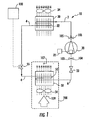
FIG. 1 is a schematic diagram illustrating an embodiment which does not form part of the present invention showing a simple refrigerant vapor compression system equipped with a constant speed compressor; -
FIG. 2 is a schematic diagram illustrating an embodiment of a simple refrigerant vapor compression system equipped with a variable speed compressor; -
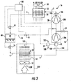
FIG. 3 is a schematic diagram illustrating a more complex refrigerant vapor compression system incorporating an economizer circuit; -
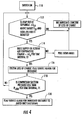
FIG. 4 is a flow chart illustrating an embodiment which does not form part of the present invention showing a method as disclosed herein for detecting and diagnosing a loss of refrigerant charge in a refrigerant vapor compression system having a fixed speed compressor, including but not limited to the refrigerant vapor compression system shown inFIG. 1 ; and -
FIG. 5 is a flow chart illustrating an embodiment of a method as disclosed herein for detecting and diagnosing a loss of refrigerant charge in a refrigerant vapor compression system having a variable speed compressor, including but not limited to the refrigerant vapor compression systems shown inFIGs. 2 and3 . - Referring initially to
FIGs. 1 - 3 of the drawing, there are depicted various exemplary embodiments of a refrigerant vapor compression system, generally designated 10, to which the method for detecting and/or diagnosing a loss of refrigerant charge as disclosed herein is applicable. The refrigerantvapor compression systems 10 are depicted in connection with refrigerating the air or other gaseous atmosphere within the temperature controlledcargo space 200 of a truck, trailer, container or the like for transporting perishable/frozen goods. However, the refrigerant vapor compression systems may also be used in conditioning air to be supplied to a climate controlled comfort zone within a residence, office building, hospital, school, restaurant or other facility, or in refrigerating air supplied to display cases, merchandisers, freezer cabinets, cold rooms or other perishable/frozen product storage areas in commercial establishments. - Each of the refrigerant
vapor compression systems 10 includes arefrigerant compression device 20, a refrigerant heatrejection heat exchanger 30, a refrigerant heatabsorption heat exchanger 50, and anelectronic expansion valve 55 operatively associated with the refrigerant heatabsorption heat exchanger 50, withrefrigerant lines 2, 4 and 6 connecting the aforementioned components in a refrigerant circuit in accordance with a conventional refrigeration cycle. The refrigerantvapor compression systems 10 are filled, i.e. charged, with a total amount of refrigerant predetermined to provide sufficient refrigerant within the system to ensure proper performance of the system under most contemplated operating conditions, herein referred to as the refrigeration charge. - The refrigerant
vapor compression systems 10 depicted inFIGs. 1 and2 are basic non-economized systems. These systems are typically charged with a refrigerant having a relatively high critical point, such as conventional hydrochlorofluorocarbon and hdyrofluorocarbon refrigerants, and are operated in a subcritical cycle. In a refrigerant vapor compression system operating in a subcritical cycle, the refrigerant heatrejection heat exchanger 30 functions as a refrigerant condenser and the refrigerant heatabsorption heat exchanger 50 functions as a refrigerant evaporator. - The
refrigeration system 10 depicted inFIG. 3 is designed for operation in a transcritical cycle and is charged with a refrigerant having a relatively low critical point, such as for example, but not limited to, carbon dioxide and refrigerant mixtures containing carbon dioxide, referred to herein by the common term: carbon dioxide refrigerant. In a refrigerant vapor compression system operating in a transcritical cycle, the refrigerant heatrejection heat exchanger 30 functions a gas (refrigerant vapor) cooler and the refrigerant heatabsorption heat exchanger 50 functions as a refrigerant evaporator. However, it is to be understood that the refrigerantvapor compression system 10 depicted inFIG. 3 may also be operated in a subcritical cycle with a relatively high critical point, such as conventional hydrochlorofluorocarbon and hdyrofluorocarbon refrigerants. - The
compression device 20 functions to compress refrigerant vapor from a lower suction pressure to a higher discharge pressure and to circulate refrigerant through the primary refrigerant circuit. InFIGs. 1 and2 , thecompression device 20 may comprise a single compressor, such as for example, but not limited to, a reciprocating compressor, a scroll compressor, a screw compressor, a rotary compressor, or any other type of refrigerant compressor or a combination of any such compressors, as desired for a particular application of the refrigerantvapor compression system 10. InFIG. 1 , thecompressor 20 is driven at a constant speed by a constant speed motor (housed within the compressor 20) driven by aconstant speed drive 25. With a constant speed compressor, the refrigerationvapor compression system 10 may optionally also include a suction modulation valve (SMV) 23 interdisposed in refrigerant line 6 at a location between the outlet of the refrigeration heatabsorption heat exchanger 50 and the suction inlet to thecompression device 20, as depicted inFIG. 1 , to provide capacity modulation functionality. In the embodiment depicted inFIG. 2 , thecompressor 20 is driven at multiple speeds by a variable speed motor (housed within the compressor 20) driven by avariable frequency drive 27. - In the embodiment depicted in
FIG. 3 , thecompression device 20 comprises a variable speed compression device driven by a variable frequency drive as in theFIG. 2 embodiment. The compression device may comprise a single multiple stage refrigerant compressor, such as for example, a screw compressor or a reciprocating compressor disposed in the primary refrigerant circuit and having a first compression stage 20a and a second compression stage 20b with the first compression stage feeding the second compression stage. Alternatively, thecompression device 20 may comprise a pair of independent compressors 20a and 20b, connected in series refrigerant flow relationship in the primary refrigerant circuit via a refrigerant line connecting the discharge outlet port of the first compressor 20a in refrigerant flow communication with the suction inlet port of the second compressor 20b. In the independent compressor embodiment, the compressors 20a and 20b may be scroll compressors, screw compressors, reciprocating compressors, rotary compressors or any other type of compressor or a combination of any such compressors. - In the refrigerant heat
rejection heat exchanger 30, hot, high pressure refrigerant vapor discharged from thecompression device 20 passes in heat exchange relationship with a cooling medium, such as for example, but not limited to ambient air or water, and is cooled either to a low lower temperature vapor (transcritical cycle) or condensed to a liquid (subcritical cycle). In the depicted embodiments, the refrigerant heatrejection heat exchanger 30 includes a finnedtube heat exchanger 32, such as for example a fin and round tube heat exchange coil or a fin and mini-channel flat tube heat exchanger, through which the refrigerant passes in heat exchange relationship with ambient air being drawn through the finnedtube heat exchanger 32 by the fan(s) 34 associated with thegas cooler 30. - Whether the refrigerant
vapor compression system 10 is operating in a transcritical cycle or a subcritical cycle, the refrigerant heatabsorption heat exchanger 50 serves an evaporator wherein refrigerant liquid or a mixture of refrigerant liquid and vapor is passed in heat exchange relationship with a fluid to be cooled, most commonly air, drawn from and to be returned to a temperature controlled environment, such as thecargo box 200 of a refrigerated transport truck, trailer or container, or a display case, merchandiser, freezer cabinet, cold room or other perishable/frozen product storage area in a commercial establishment, or to a climate controlled comfort zone within a residence, office building, hospital, school, restaurant or other facility. In the depicted embodiments, the refrigerant heatabsorption heat exchanger 50 comprises a finned tube heat exchanger 52 through which refrigerant passes in heat exchange relationship with air drawn from and returned to the refrigeratedcargo box 200 by the evaporator fan(s) 54 associated with theevaporator 50. The finned tube heat exchanger 52 may comprise, for example, a fin and round tube heat exchange coil or a fin and mini-channel flat tube heat exchanger. - As the amount of refrigerant circulating through the refrigerant circuit of the refrigerant vapor compression system will vary with the operating conditions to which the system is subjected, the refrigerant charge will amount to more refrigerant than is actually required under some operating conditions. Thus, it is customary to provide a buffer vessel in the refrigerant for holding refrigerant that is excess of the amount of refrigerant circulating under the then prevailing operating conditions. In the subcritical cycle systems depicted in
FIGs. 1 and2 , the refrigerantvapor compression systems 10 may include a receiver and/or an accumulator (neither shown) disposed in the refrigerant circuit as in conventional practice. In the embodiment of the refrigerantvapor compression system 10 depicted inFIG. 3 , aflash tank 40 is included in the refrigerant circuit which serves as a buffer vessel for excess refrigerant, as well as an economizer. - The refrigerant
vapor compression system 10 depicted inFIG.3 , which as mentioned before is configured for operation in a transcritical cycle, further includes an economizer circuit that includes theaforementioned flash tank 40, as well as anelectronic expansion valve 45 operatively associated with theflash tank 40, and a refrigerantvapor injection line 14. Theflash tank economizer 40 is interdisposed in refrigerant line 4 of the primary refrigerant circuit downstream with respect to refrigerant flow of the refrigerant heatrejection heat exchanger 30 and upstream with respect to refrigerant flow of the refrigerant heatabsorption heat exchanger 50. Theflash tank economizer 40 defines aseparation chamber 42 wherein refrigerant in the liquid state collects in a lower portion of theseparation chamber 42 and wherein refrigerant in the vapor state collects in the portion of theseparation chamber 42 above the liquid refrigerant. - The refrigerant
vapor injection line 14 establishes refrigerant flow communication between an upper portion of theseparation chamber 42 of theflash tank economizer 40 and an intermediate stage of the compression process. A vapor injectionflow control device 43 may be interdisposed invapor injection line 14. The vapor injectionflow control device 43 may be a flow control valve selectively positionable between an open position wherein refrigerant vapor flow may pass through the refrigerantvapor injection line 14 and a closed position wherein refrigerant vapor flow through the refrigerantvapor injection line 14 is blocked, such as for example, but not limited to, a two-position solenoid valve of the type selectively positionable between a first open position and a second closed position. - In the exemplary embodiment of the refrigerant vapor compression system depicted in
FIG. 3 , additional capacity modulation is provided by a compressor unload circuit that includesrefrigerant line 16 and unloadflow control valve 29 interdisposed inrefrigerant line 16.Refrigerant line 16 establishes refrigerant flow communication between an intermediate stage of the compression process and the suction inlet of the compression device. The unload flow control valve may have a closed position and a full open position, and optionally one or more intermediate part open positions. - The refrigerant
vapor compression system 10 also includes a control system operatively associated therewith for controlling operation of the refrigerantvapor compression system 10. The control system includes acontroller 100 that determines the desired mode of operation in which to operate the refrigerantvapor compression system 10 based upon consideration of refrigeration load requirements, ambient conditions and various sensed system operating parameters and controls operation of various system components, including but not limited to thecompression device 20, thefans electronic expansion valve 55. As in conventional practice, thecontroller 100 also includes various sensors operatively associated with thecontroller 100 and disposed at selected locations throughout the system for monitoring various operating parameters by means of various sensors operatively associated with the controller, such as by way of example, but not limitation, atemperature sensor 103 and apressure sensor 104 for sensing the refrigerant suction temperature and pressure, respectively, atemperature sensor 105 and apressure sensor 106 for sensing refrigerant discharge temperature and pressure, respectively, and an ambient air temperature sensor (not shown) for sensing outdoor air temperature, all not shown. On a refrigerantvapor compression system 10 equipped with avariable speed drive 27 for driving thecompression device 20 at multiple speeds, the control system further includes asensor 102 for sensing the speed of thecompression drive 20 and asensor 108 for sensing the current drawn by thecompression device 20. - In the refrigerant vapor compression system disclosed herein, the
controller 100 is configured to detect and diagnose, in real time, a refrigerant charge loss in accordance with the method disclosed herein. Thecontroller 100 is further configured to flag an alarm in the event a refrigerant charge loss is detected. Thecontroller 100 may be configured to flag either a service alarm or a shut down alarm, depending upon the degree of the detected refrigerant charge loss. In response to the alarm, appropriate action may be taken to prevent a resultant loss in cooling capacity and to protector thecompression device 20 and other components of the refrigerantvapor compression system 10 from damage as a result as continued operation with an inadequate refrigerant charge.FIGs. 4 and5 present flow charts depicting the method disclosed herein for detecting and diagnosing a system refrigerant charge loss.Fig. 4 depicts the method as applied to a refrigerant vapor compression system having a constant speed compression device, andFig. 5 depicts the method as applied to a refrigerant vapor compression system equipped with a variable speed compression device. - To detect a refrigerant charge loss, the
controller 100 monitors the amount of superheat in the refrigerant vapor leaving theevaporator 50, referred to herein as the evaporator outlet superheat, EOSH, and the degree of openness of theelectronic expansion valve electronic expansion valve 55 is an output signal from theelectronic expansion valve 55 that is recorded by thecontroller 100. Thecontroller 100 uses the refrigerant suction temperature sensed bytemperature sensor 103 and the refrigerant suction pressure sensed bypressure sensor 104 to calculate the evaporator outlet superheat according to conventional techniques. - Referring now to
FIGs. 4 and5 , thecontroller 100 atblock 110 at selected intervals initiates the method for detecting and diagnosing a refrigerant charge loss. Atblock 112, thecontroller 100 compares the sensed evaporator outlet superheat, EOSHSENSED, to a preset target evaporator outlet superheat, EOSHTARGET, to determine whether EOSHSENSED is greater than EOSHTARGET by at least a preset amount ΔEOSH. Thecontroller 100 also compares the sensed degree of openness of theelectronic expansion valve 55, OPENSENSED, to a preset upper limit for the degree of openness, OPENLIMIT, for theelectronic expansion valve 55. If the sensed evaporator outlet superheat EOSHSENSED is greater than EOSHTARGET by at least the preset amount ΔEOSH, for example by a preset amount in the range from at least 5°F (2.8 °C) to 20°F (11.1°C), and in a particular embodiment wherein the system is charged with a carbon dioxide refrigerant at least 10°F (5.5 °C), and the sensed degree of openness, OPENSENSED, of theelectronic expansion valve 55 is greater than OPENLIMIT, for example greater than 90%, for a preset period of time, t1, for example at least 3 minutes to 10 minutes, and in an embodiment greater than 95% for at least 5 minutes, thecontroller 100 performs a check to determine the then current operating mode of the refrigerant vapor compression system. - To determine the current operating mode of the refrigerant vapor compression system, at
block 114, thecontroller 100 determines the then current rate of change of at least one of the temperature, TS, of the supply air having traversed theevaporator 50 and being supplied to the climate controlled space, which in the depicted embodiments iscargo space 200, or the temperature, TR, of the return air returning from the climate control space to pass through theevaporator 50. The transport refrigerantvapor compression system 100 includes at least one of or both of, asensor 107 for sensing the temperature, TS, of the supply air and asensor 109 for sensing the temperature, TR, of the return air. The controller is configured to monitor thesensors vapor compression system 10 is operating in a steady state mode to maintain the air temperature within thecargo space 200 at a preset temperature. However, if the rate of change ΔTS or ΔTR is more than a preset rate of temperature change, ΔTair, the refrigerantvapor compression system 10 is operating in a pulldown mode to rapidly reduce the air temperature within thecargo space 200. - If the
controller 100 determines that the refrigerantvapor compression system 10 is operating in a steady state mode with the sensed evaporator outlet superheat EOSHSENSED being greater than EOSHTARGET by at least the preset amount ΔESOH and the sensed degree of openness, OPENSENSED, of theelectronic expansion valve 55 being greater than OPENLIMIT, thecontroller 100 understands that the sensed evaporator outlet superheat and the degree of openness of theelectronic expansion valve 55 are excessive and therefore indicative of a loss of refrigerant charge resulting in an inadequate refrigerant charge. Having determined that a loss of refrigerant charge has occurred, thecontroller 100 atblock 116 generates a service alarm flagging the need for a refrigerant recharge. - If the refrigerant
vapor compression system 10 is equipped with aconstant speed compressor 20, thecontroller 100 next proceeds as further depicted inFIG. 4 to diagnose the severity of the refrigerant charge loss. Atblock 118, compares the compressor suction pressure, PSSENSED, to a preset low suction pressure limit, PLOW, If the compressor suction pressure, PSSENSED, is less than the preset low suction pressure limit, PLOW, for a time interval, t4, thecontroller 100 atblock 120, generates an alarm flagging a shut down warning. If an immediate system refrigerant recharge is not performed, thecontroller 100 shuts the system down. However, if the compressor suction pressure, PSSENSED, is not less than the preset low suction pressure limit, PLOW, for a time interval, t4,controller 100 returns to block 112 and repeats the method. For a refrigerant vapor compression system charged with a carbon dioxide refrigerant,controller 100 may be configured to flag at shut down warning atblock 120 if the compressor suction pressure, PSSENSED, is less than the preset low suction pressure limit, PLOW, in the range of from 120 psia (8.3 bars) to 200 psia (13.8 bars), for the specified time interval, t4. In an embodiment, thecontroller 100 may be configured to flag a shut down warning atblock 120 if the compressor suction pressure, PSSENSED, is less than the preset low suction pressure limit, PLOW, of about 150 psia (10.3 bars) for a time interval of one minute. For clarity, psia refers to pounds per square inch absolute. - According to the invention the refrigerant
vapor compression system 10 is equipped with avariable speed compressor 20, thecontroller 100 next proceeds as further depicted inFIG. 5 to diagnose the severity of the refrigerant charge loss by first checking whether the compressor is operating at maximum speed. Atblock 117, the controller100 determines whether thecompressor 20 has been operating at maximum speed for a predetermined time interval, t3, for example five minutes. If thecompressor 20 has not been operating at maximum speed for the predetermined tine interval, t3, the controller proceeds to perform the suction pressure comparison atblock 118 as discussed above and to flag a shut down alarm atblock 120 if the compressor suction pressure, PSSENSED, is less than the preset low suction pressure limit, PLOW, for a time interval, t4, or if the compressor suction pressure, PSSENSED, is not less than the preset low suction pressure limit, PLOW, for a time interval, t4, thecontroller 100 returns to block 112 and repeats the method. - However, if the
controller 100 determines atblock 117 that thecompressor 20 has been operating at maximum speed for the predetermined tine interval, t3, thecontroller 100 will, atblock 119, check the current being drawn by thecompressor 20 in comparison a maximum current draw limit. If the sensed compressor current draw is greater than a preset percentage, Y%, of the maximum current draw limit, thecontroller 100, atblock 121, reduces the speed of thecompressor 20 in a series of step reductions until the sensed current draw drops below the preset percentage, Y%, of the maximum current draw limit. If atblock 119, thecontroller 100 determines that the sensed current draw is not greater than the preset percentage, Y%, of the maximum current draw limit, thecontroller 100 returns to block 112 and repeats the method. - In a further aspect of the disclosure, the
controller 100 may be configured to calculate the actual refrigerant charge level. If the ambient air temperature is higher than 87°F (30.5°C) and thecompressor 20 has been off for more than a sufficient time to permit the refrigerant within the refrigerantvapor compression system 10 to migrate to an equilibrium condition, for example more than twenty minutes, thecontroller 100 may initiate a refrigerant charge calculation. At the equilibrium condition, the refrigerant pressure is substantially equalized throughout the system and the refrigerant will be at ambient temperature. To calculate the actual refrigerant charge, thecontroller 100 first calculates the refrigerant density based on the sensed discharge pressure and the ambient air temperature, and then multiplies the calculated refrigerant density with the internal volume of thesystem 10, thereby determining the weight of refrigerant currently resident within thesystem 10, i.e. the actual refrigerant charge. Thecontroller 100 may also be configured to compare the calculated system refrigerant charge to a design system refrigerant charge, for example a factory installed system refrigerant charge, and to generate an alarm flagging a loss of refrigerant charge is the calculated is less than a specified percent of the preferred system refrigerant charge, for example less than 85% of the design system refrigerant charge. In an embodiment, thecontroller 100 is configured to initiate a refrigerant charge calculation upon completion of an evaporator defrost cycle before restarting thecompression device 20 to return thesystem 10 to operation in a cooling mode.
Claims (11)
- A method for detecting in real-time a refrigerant charge loss in a refrigerant vapor compression system (10) having a refrigerant circuit including a refrigerant compression device (20), a refrigerant heat rejection heat exchanger (30), an evaporator (50) and an electronic expansion valve (55) operatively associated with the evaporator (50), the method comprising:determining whether both a sensed evaporator outlet superheat exceeds a target evaporator outlet superheat by at least a preset amount of superheat and a sensed degree of openness of the electronic expansion valve (55) exceeds a preset degree of openness for a preset time of period; characterized in that if both the sensed evaporator outlet superheat exceeds the target evaporator outlet superheat by at least the preset amount of superheat and the sensed degree of openness of the electronic expansion valve (55) exceeds the preset degree of openness for the preset time of period, determining whether at least one air temperature of a sensed supply air temperature of a flow of air having traversed the evaporator (50) or a sensed return air temperature of a flow of air returning to the evaporator (50) is changing at a rate less than a preset air temperature rate of change;if the at least one air temperature of the sensed supply air temperature of a flow of air having traversed the evaporator (50) or the sensed return air temperature of a flow of air returning to the evaporator (50) is changing at a rate less than the preset air temperature rate of change, generating a service alarm indicating a loss of charge warning and determining whether a sensed speed of the compression device (20) is at a maximum speed limit for the compression device (20) for a predetermined period of time.
- The method as set forth in claim 1 further comprising:
if the at least one air temperature of the sensed supply air temperature of a flow of air having traversed the evaporator (50) or the sensed return air temperature of a flow of air returning to the evaporator (50) is changing at a rate less than the preset air temperature rate of change, comparing a sensed suction pressure of refrigerant passing to a suction inlet to the compression device (20) to a preset low suction pressure limit, and if the sensed suction pressure of refrigerant passing to a suction inlet to the compression device (20) is less than the preset low suction pressure limit for a preset period of time, generating a shut down alarm warning an urgent system refrigerant recharge is required. - The method as set forth in claim 1 further comprising:
if the sensed speed of the compression device (20) is less than the preset maximum speed limit for the speed of the compression device (20), comparing a sensed suction pressure of refrigerant passing to a suction inlet to the compression device (20) to a preset low suction pressure limit, and if the sensed suction pressure of refrigerant passing to a suction inlet to the compression device (20) is less than the preset low suction pressure limit for a preset period of time, generating a service alarm indicating an urgent system refrigerant recharge required warning. - The method as set forth in claim 1 further comprising:
if the sensed speed of the compression device (20) is at the maximum speed limit for the speed of the compression device (20) throughout a preset time interval, comparing a sensed current draw by the compression device (20) to a maximum current draw limit. - The method as set forth in claim 4 further comprising:
if the sensed current draw exceeds a preset percentage of the maximum current draw limit, reducing the speed of the compression device (20) to a lower speed at which the current draw associated with said lower speed is below the preset percentage of the maximum current draw limit. - The method as set forth in claim 5 wherein the preset percentage of the maximum current draw limit is at least 90% of the maximum current draw.
- The method as set forth in claim 4 wherein the preset time interval is at least 3 minutes to 10 minutes.
- The method as set forth in claim 1 further if both the sensed evaporator outlet superheat exceeds the target evaporator outlet superheat by a selected amount in range from at least 2.8 °C (5 °F) to 11.1 °C (20 °F) and the sensed degree of openness of the electronic expansion valve (55) exceeds 90% of openness for at least 5 minutes, then determining whether at least one air temperature of a sensed supply air temperature of a flow of air having traversed the evaporator (50) or a sensed return air temperature of a flow of air returning to the evaporator (50) is changing at a rate less than a preset air temperature rate of change.
- The method as set forth in claim 1 wherein the preset air temperature rate of change is 0.27 °C (0.5 °F) per minute.
- The method as set forth in claim 2 wherein the refrigerant comprises a carbon dioxide refrigerant and the present low suction pressure limit is a pressure in the range from 8.3 bars absolute (120 psi absolute) to 13.8 bars (200 psi absolute).
- The method as set forth in claim 10 wherein the preset low suction pressure limit is about 10.3 bars (150 psi absolute).
Applications Claiming Priority (2)
| Application Number | Priority Date | Filing Date | Title |
|---|---|---|---|
| US201261597275P | 2012-02-10 | 2012-02-10 | |
| PCT/US2013/024575 WO2013119489A2 (en) | 2012-02-10 | 2013-02-04 | Method for detection of loss of refrigerant |
Publications (2)
| Publication Number | Publication Date |
|---|---|
| EP2812640A2 EP2812640A2 (en) | 2014-12-17 |
| EP2812640B1 true EP2812640B1 (en) | 2018-08-08 |
Family
ID=47750803
Family Applications (1)
| Application Number | Title | Priority Date | Filing Date |
|---|---|---|---|
| EP13706332.7A Active EP2812640B1 (en) | 2012-02-10 | 2013-02-04 | Method for detection of loss of refrigerant |
Country Status (6)
| Country | Link |
|---|---|
| US (1) | US9869499B2 (en) |
| EP (1) | EP2812640B1 (en) |
| CN (1) | CN104204697B (en) |
| DK (1) | DK2812640T3 (en) |
| SG (1) | SG11201404722YA (en) |
| WO (1) | WO2013119489A2 (en) |
Families Citing this family (48)
| Publication number | Priority date | Publication date | Assignee | Title |
|---|---|---|---|---|
| US9746224B2 (en) | 2012-11-21 | 2017-08-29 | Liebert Corporation | Expansion valve setpoint control systems and methods |
| US10174977B2 (en) | 2012-11-21 | 2019-01-08 | Vertiv Corporation | Apparatus and method for subcooling control based on superheat setpoint control |
| JP5818849B2 (en) * | 2013-08-26 | 2015-11-18 | 三菱電機株式会社 | Air conditioner and refrigerant leakage detection method |
| US20150362239A1 (en) * | 2014-06-12 | 2015-12-17 | Chao-Cheng Chen | Variable frequency control apparatus |
| US9638446B2 (en) * | 2014-09-03 | 2017-05-02 | Mahle International Gmbh | Method to detect low charge levels in a refrigeration circuit |
| DE102014013653B4 (en) * | 2014-09-15 | 2016-04-07 | Adwatec Oy | Arrangement and method for cooling liquid-cooled electronics |
| DE102014221106B4 (en) * | 2014-10-17 | 2026-04-16 | Bayerische Motoren Werke Aktiengesellschaft | Method and device for controlling or regulating a vehicle air conditioning refrigerant circuit |
| EP3348938B1 (en) * | 2015-09-07 | 2019-11-27 | Mitsubishi Electric Corporation | Refrigeration cycle system |
| US9869492B2 (en) * | 2015-10-12 | 2018-01-16 | Heatcraft Refrigeration Products Llc | Air conditioning and refrigeration system |
| ES2748013T3 (en) | 2015-11-17 | 2020-03-12 | Carrier Corp | Procedure to detect a loss of refrigerant charge in a refrigeration system |
| US9874384B2 (en) * | 2016-01-13 | 2018-01-23 | Bergstrom, Inc. | Refrigeration system with superheating, sub-cooling and refrigerant charge level control |
| US10578328B2 (en) | 2016-02-11 | 2020-03-03 | Vertiv Corporation | Systems and methods for detecting degradation of a component in an air conditioning system |
| AU201712794S (en) | 2016-11-23 | 2017-05-23 | Dometic Sweden Ab | Ventilation and air conditioning apparatus |
| CN107101323A (en) * | 2017-04-13 | 2017-08-29 | 青岛海尔空调电子有限公司 | The coolant quantity detection method and device of air conditioner |
| DE112018005883B4 (en) | 2017-11-16 | 2025-12-18 | Dometic Sweden Ab | Air conditioning device for motorhomes, motorhome and method for supplying conditioned air into a motorhome |
| CN110375466B (en) | 2018-04-13 | 2022-10-28 | 开利公司 | Device and method for detecting refrigerant leakage of air source heat pump system |
| CN110375468B (en) | 2018-04-13 | 2022-10-11 | 开利公司 | Air-cooled heat pump system, and refrigerant leakage detection method and detection system for same |
| US10830501B2 (en) * | 2018-04-25 | 2020-11-10 | Johnson Controls Technology Company | Systems for detecting and positioning of reversing valve |
| CN110792922A (en) * | 2018-08-01 | 2020-02-14 | 乔治洛德方法研究和开发液化空气有限公司 | Device and method for filling a container with a pressurized gas |
| DK3604890T3 (en) * | 2018-08-01 | 2023-08-21 | Air Liquide | DEVICE AND PROCEDURE FOR FILLING CONTAINERS WITH PRESSURED GAS |
| CN110792923A (en) | 2018-08-01 | 2020-02-14 | 乔治洛德方法研究和开发液化空气有限公司 | Device and method for filling a container with a pressurized gas |
| EP3604891B1 (en) * | 2018-08-01 | 2022-10-12 | L'air Liquide, Societe Anonyme Pour L'etude Et L'exploitation Des Procedes Georges Claude | Device and process for refuelling containers with pressurized gas |
| US11506339B2 (en) | 2018-08-01 | 2022-11-22 | L'air Liquide, Societe Anonyme Pour L'etude Et L'exploitation Des Procedes Georges Claude | Device and process for refueling containers with pressurized gas |
| US11499765B2 (en) | 2018-08-01 | 2022-11-15 | L'air Liquide, Societe Anonyme Pour L'etude Et L'exploitation Des Procedes Georges Claude | Device and process for refueling containers with pressurized gas |
| USD905217S1 (en) | 2018-09-05 | 2020-12-15 | Dometic Sweden Ab | Air conditioning apparatus |
| US10844860B2 (en) | 2018-12-21 | 2020-11-24 | Trane International Inc. | Method of improved control for variable volume ratio valve |
| US11104230B2 (en) * | 2019-01-18 | 2021-08-31 | Thermo King Corporation | Multi-source power management for a transport refrigeration system |
| CN111692703B (en) | 2019-03-15 | 2023-04-25 | 开利公司 | Fault detection method for air conditioning system |
| JP2020153564A (en) * | 2019-03-19 | 2020-09-24 | ダイキン工業株式会社 | Refrigerant amount judgment kit |
| CN112424545B (en) * | 2019-05-24 | 2023-10-20 | 开利公司 | Low refrigerant charge detection in a transport refrigeration system |
| US11131497B2 (en) * | 2019-06-18 | 2021-09-28 | Honeywell International Inc. | Method and system for controlling the defrost cycle of a vapor compression system for increased energy efficiency |
| US11231198B2 (en) | 2019-09-05 | 2022-01-25 | Trane International Inc. | Systems and methods for refrigerant leak detection in a climate control system |
| EP4028703A1 (en) * | 2019-09-12 | 2022-07-20 | Carrier Corporation | Dual temperature sensor arrangement to detect refrigerant leak |
| IT201900019193A1 (en) * | 2019-10-17 | 2021-04-17 | Dometic Sweden Ab | AIR CONDITIONING APPARATUS FOR RECREATIONAL VEHICLES |
| CN113251711B (en) * | 2020-02-12 | 2022-06-07 | 合肥华凌股份有限公司 | Method, device, equipment and storage medium for judging filling state of mixed refrigerant |
| PL3869125T3 (en) * | 2020-02-20 | 2025-03-03 | Cryo Pur | Refrigeration system and operating method thereof |
| US11441968B2 (en) | 2020-02-28 | 2022-09-13 | Rolls-Royce North American Technologies Inc. | System and method for detecting leaks in a sealed coolant system |
| US11674726B2 (en) * | 2020-06-30 | 2023-06-13 | Thermo King Llc | Systems and methods for transport climate control circuit management and isolation |
| US12209777B2 (en) * | 2020-07-07 | 2025-01-28 | Carrier Corporation | Magnetic bearing compressor protection |
| CN112378134B (en) * | 2020-11-20 | 2021-09-14 | 珠海格力电器股份有限公司 | Refrigerator and refrigerant leakage detection method thereof |
| KR20220157161A (en) * | 2021-05-20 | 2022-11-29 | 한온시스템 주식회사 | Compressor and control method of compressor |
| US12487008B2 (en) | 2022-01-14 | 2025-12-02 | Trane International Inc. | Method of commissioning an HVAC system |
| US12370867B2 (en) * | 2022-05-06 | 2025-07-29 | Ford Global Technologies, Llc | Vehicle configured to detect low refrigerant charge |
| US12117191B2 (en) | 2022-06-24 | 2024-10-15 | Trane International Inc. | Climate control system with improved leak detector |
| US12523404B2 (en) | 2023-01-25 | 2026-01-13 | Copeland Lp | Retrofit for fan control in refrigerated cases |
| US12359856B2 (en) * | 2023-08-01 | 2025-07-15 | Axiom Cloud Inc. | System and method for detection of refrigerant leaks |
| US20250074155A1 (en) * | 2023-09-06 | 2025-03-06 | Ford Global Technologies, Llc | Method and system for low charge detection |
| US20260049748A1 (en) * | 2024-08-16 | 2026-02-19 | Hill Phoenix, Inc. | Dual temperature refrigeration system |
Family Cites Families (77)
| Publication number | Priority date | Publication date | Assignee | Title |
|---|---|---|---|---|
| US2160276A (en) | 1937-04-29 | 1939-05-30 | Thomas C Mckee | Liquid level indicator |
| US2893217A (en) | 1955-10-10 | 1959-07-07 | Joseph G Nigro | Automatic refrigerant charging system coupled with an automatic alarm to a conventional warning system |
| US3491544A (en) | 1968-04-25 | 1970-01-27 | Robert C Webber | Method and apparatus for guarding refrigeration systems |
| US4008755A (en) | 1973-01-24 | 1977-02-22 | Siemens Aktiengesellschaft | Leak indicating apparatus for a closed cooling system of an electric machine |
| JPS58198632A (en) | 1982-04-28 | 1983-11-18 | Hitachi Plant Eng & Constr Co Ltd | Alarming device for air conditioner |
| USRE32451E (en) | 1983-05-23 | 1987-07-07 | Murray Corporation | Weight-monitored air-conditioner charging station |
| US4856288A (en) | 1983-07-18 | 1989-08-15 | Weber Robert C | Refrigerant alert and automatic recharging device |
| US4588580B2 (en) | 1984-07-23 | 1999-02-16 | Alaz Corp | Transdermal administration of fentanyl and device therefor |
| US4633681A (en) | 1985-08-19 | 1987-01-06 | Webber Robert C | Refrigerant expansion device |
| US4711096A (en) | 1986-03-17 | 1987-12-08 | Krantz Herman F | Leak detection and refrigerant purging system |
| JPH0638007B2 (en) * | 1986-03-28 | 1994-05-18 | 株式会社東芝 | Refrigerator capacity control method |
| JPH01300170A (en) | 1988-05-25 | 1989-12-04 | Daikin Ind Ltd | Air conditioner |
| DE4008877A1 (en) | 1988-09-22 | 1991-10-02 | Danfoss As | Refrigerator with expansion value and evaporator - are connected in series circuit and with expansion value control unit for maintaining desired temp. in work space |
| US5009076A (en) | 1990-03-08 | 1991-04-23 | Temperature Engineering Corp. | Refrigerant loss monitor |
| US5323847A (en) | 1990-08-01 | 1994-06-28 | Hitachi, Ltd. | Electronic apparatus and method of cooling the same |
| US5079930A (en) | 1990-12-03 | 1992-01-14 | Atron, Inc. | Apparatus and method for monitoring refrigeration system |
| US5264833A (en) | 1991-06-28 | 1993-11-23 | Edward Jeffers | Automatic leak detector |
| US5174125A (en) | 1991-07-24 | 1992-12-29 | Donald Duncan | Device for detecting loss of refrigerant in an airconditioner |
| US5228304A (en) | 1992-06-04 | 1993-07-20 | Ryan David J | Refrigerant loss detector and alarm |
| US5186014A (en) | 1992-07-13 | 1993-02-16 | General Motors Corporation | Low refrigerant charge detection system for a heat pump |
| US5243829A (en) * | 1992-10-21 | 1993-09-14 | General Electric Company | Low refrigerant charge detection using thermal expansion valve stroke measurement |
| US5337576A (en) | 1992-12-28 | 1994-08-16 | Rite Charge Corporation | Refrigerant and H.V.A.C. ducting leak detector |
| US5351037A (en) | 1993-01-22 | 1994-09-27 | J And N Associates, Inc. | Refrigerant gas leak detector |
| US5351500A (en) | 1993-12-03 | 1994-10-04 | Texas Medical Center Central Heating And Cooling Cooperative Association | Refrigerant leak detector system |
| US5457965A (en) | 1994-04-11 | 1995-10-17 | Ford Motor Company | Low refrigerant charge detection system |
| US5684463A (en) | 1994-05-23 | 1997-11-04 | Diercks; Richard Lee Roi | Electronic refrigeration and air conditioner monitor and alarm |
| US5539385A (en) | 1995-04-21 | 1996-07-23 | Carrier Corporation | System for monitoring condenser pressure |
| US6047557A (en) | 1995-06-07 | 2000-04-11 | Copeland Corporation | Adaptive control for a refrigeration system using pulse width modulated duty cycle scroll compressor |
| JPH09178306A (en) * | 1995-12-22 | 1997-07-11 | Denso Corp | Refrigeration cycle equipment |
| US5860286A (en) | 1997-06-06 | 1999-01-19 | Carrier Corporation | System monitoring refrigeration charge |
| JPH1194408A (en) | 1997-09-19 | 1999-04-09 | Sanyo Electric Co Ltd | Detecting device of leak of refrigerant for refrigerating equipment |
| JPH11230648A (en) | 1998-02-13 | 1999-08-27 | Matsushita Electric Ind Co Ltd | Refrigerant leakage alarm device for refrigeration equipment using flammable refrigerant |
| US6122955A (en) | 1998-09-17 | 2000-09-26 | Hoog; Hollis Ellsworth | Liquid leak detector |
| JP3490908B2 (en) | 1998-09-30 | 2004-01-26 | 三洋電機株式会社 | Refrigerant refrigerant leak detection system |
| US6098412A (en) | 1999-01-19 | 2000-08-08 | Carrier Corporation | Method for automated detection of leaks in a discharge check valve |
| DE19935226C1 (en) * | 1999-07-27 | 2001-02-15 | Daimler Chrysler Ag | Procedure for monitoring the refrigerant level in a refrigeration system |
| US6425253B1 (en) | 2000-06-02 | 2002-07-30 | Daimlerchrysler Corporation | Method for detecting low-charge condition in air conditioning system and device incorporating same |
| US7512523B2 (en) | 2000-06-16 | 2009-03-31 | Verisae, Inc. | Refrigerant loss tracking and repair |
| JP2002039649A (en) | 2000-07-24 | 2002-02-06 | Funai Electric Co Ltd | Operation alarm device of air conditioner |
| US6460354B2 (en) * | 2000-11-30 | 2002-10-08 | Parker-Hannifin Corporation | Method and apparatus for detecting low refrigerant charge |
| CN1314930C (en) | 2002-01-15 | 2007-05-09 | 株式会社东芝 | Refrigerator with alarm device for alarming refrigerant leakage |
| US6868678B2 (en) | 2002-03-26 | 2005-03-22 | Ut-Battelle, Llc | Non-intrusive refrigerant charge indicator |
| US6772598B1 (en) | 2002-05-16 | 2004-08-10 | R.S. Services, Inc. | Refrigerant leak detection system |
| US7490477B2 (en) | 2003-04-30 | 2009-02-17 | Emerson Retail Services, Inc. | System and method for monitoring a condenser of a refrigeration system |
| KR20050028391A (en) | 2003-09-17 | 2005-03-23 | 엘지전자 주식회사 | A refrigerants leakage sensing system and method |
| US6826948B1 (en) | 2003-10-09 | 2004-12-07 | Delphi Technologies, Inc. | Leak detection apparatus for a liquid circulation cooling system |
| US6964173B2 (en) | 2003-10-28 | 2005-11-15 | Carrier Corporation | Expansion device with low refrigerant charge monitoring |
| US7343750B2 (en) | 2003-12-10 | 2008-03-18 | Carrier Corporation | Diagnosing a loss of refrigerant charge in a refrigerant system |
| US20050126190A1 (en) | 2003-12-10 | 2005-06-16 | Alexander Lifson | Loss of refrigerant charge and expansion valve malfunction detection |
| US20050238533A1 (en) | 2004-03-15 | 2005-10-27 | Michael Jansen | Refrigerant leak detector |
| US6981384B2 (en) | 2004-03-22 | 2006-01-03 | Carrier Corporation | Monitoring refrigerant charge |
| US7412842B2 (en) | 2004-04-27 | 2008-08-19 | Emerson Climate Technologies, Inc. | Compressor diagnostic and protection system |
| US8109104B2 (en) | 2004-08-25 | 2012-02-07 | York International Corporation | System and method for detecting decreased performance in a refrigeration system |
| CN100549574C (en) * | 2004-08-27 | 2009-10-14 | 开利公司 | Fault Diagnosis and Prediction Based on Distance Fault Classifier |
| US7188482B2 (en) * | 2004-08-27 | 2007-03-13 | Carrier Corporation | Fault diagnostics and prognostics based on distance fault classifiers |
| US7712319B2 (en) | 2004-12-27 | 2010-05-11 | Carrier Corporation | Refrigerant charge adequacy gauge |
| US7380404B2 (en) | 2005-01-05 | 2008-06-03 | Carrier Corporation | Method and control for determining low refrigerant charge |
| US7076373B1 (en) | 2005-01-14 | 2006-07-11 | Honeywell International Inc. | Leak detection system for a water heater |
| US7377118B2 (en) | 2005-02-16 | 2008-05-27 | Zero Zone, Inc. | Refrigerant tracking/leak detection system and method |
| GB2428896A (en) | 2005-07-26 | 2007-02-07 | Trox | Detecting a leak in a cooling system |
| WO2007022779A1 (en) | 2005-08-25 | 2007-03-01 | Knudsen Køling A/S | Refrigerant leakage detection |
| JP4928763B2 (en) * | 2005-09-28 | 2012-05-09 | 三菱重工業株式会社 | Control device for electric compressor |
| US7665315B2 (en) | 2005-10-21 | 2010-02-23 | Emerson Retail Services, Inc. | Proofing a refrigeration system operating state |
| US7386985B2 (en) | 2005-12-05 | 2008-06-17 | Carrier Corporation | Detection of refrigerant charge adequacy based on multiple temperature measurements |
| US8037700B2 (en) | 2006-01-23 | 2011-10-18 | Carrier Corporation | Air conditioning system for low ambient cooling |
| JP2007302020A (en) * | 2006-05-08 | 2007-11-22 | Denso Corp | Air conditioner for vehicles |
| US7765818B2 (en) | 2006-05-30 | 2010-08-03 | B/E Aerospace, Inc. | Refrigeration unit and diagnostic method therefor |
| EP1916492A1 (en) | 2006-10-25 | 2008-04-30 | Air Liquide Sanità Service S.p.A. | Control system for a cryopreservation facility |
| WO2008157757A1 (en) | 2007-06-21 | 2008-12-24 | E. I. Du Pont De Nemours And Company | Method for leak detection in heat transfer system |
| US20090019875A1 (en) | 2007-07-19 | 2009-01-22 | American Power Conversion Corporation | A/v cooling system and method |
| US20090107157A1 (en) | 2007-10-25 | 2009-04-30 | Serge Dube | Refrigerant leak-detection systems |
| KR101488390B1 (en) | 2008-02-05 | 2015-01-30 | 엘지전자 주식회사 | Method for calculating the mass of a refrigerant in air conditioning apparatus |
| JP4803199B2 (en) | 2008-03-27 | 2011-10-26 | 株式会社デンソー | Refrigeration cycle equipment |
| JP5040975B2 (en) | 2008-09-30 | 2012-10-03 | ダイキン工業株式会社 | Leakage diagnostic device |
| CN202133061U (en) | 2008-11-26 | 2012-02-01 | 德尔福技术有限公司 | Refrigerant leakage detection system and refrigerant sensor assembly thereof |
| US8973380B2 (en) | 2009-05-28 | 2015-03-10 | Schneider Electric It Corporation | Systems and methods for detecting refrigerant leaks in cooling systems |
| US20110112814A1 (en) | 2009-11-11 | 2011-05-12 | Emerson Retail Services, Inc. | Refrigerant leak detection system and method |
-
2013
- 2013-02-04 SG SG11201404722YA patent/SG11201404722YA/en unknown
- 2013-02-04 DK DK13706332.7T patent/DK2812640T3/en active
- 2013-02-04 US US14/376,890 patent/US9869499B2/en active Active
- 2013-02-04 CN CN201380008779.5A patent/CN104204697B/en active Active
- 2013-02-04 WO PCT/US2013/024575 patent/WO2013119489A2/en not_active Ceased
- 2013-02-04 EP EP13706332.7A patent/EP2812640B1/en active Active
Non-Patent Citations (1)
| Title |
|---|
| None * |
Also Published As
| Publication number | Publication date |
|---|---|
| EP2812640A2 (en) | 2014-12-17 |
| CN104204697B (en) | 2017-02-22 |
| DK2812640T3 (en) | 2018-11-26 |
| US9869499B2 (en) | 2018-01-16 |
| WO2013119489A2 (en) | 2013-08-15 |
| SG11201404722YA (en) | 2014-10-30 |
| CN104204697A (en) | 2014-12-10 |
| US20150007591A1 (en) | 2015-01-08 |
| WO2013119489A3 (en) | 2014-01-30 |
Similar Documents
| Publication | Publication Date | Title |
|---|---|---|
| EP2812640B1 (en) | Method for detection of loss of refrigerant | |
| EP2491317B1 (en) | Refrigerant vapor compression system operation | |
| EP2545331B1 (en) | Defrost operations and apparatus for a transport refrigeration system | |
| DK2880375T3 (en) | DETECTION OF FROZEN EVAPER HOSE AND STARTING OF DEFROST | |
| EP2491318B1 (en) | Parameter control in transport refrigeration system and methods for same | |
| EP2737264B1 (en) | Startup logic for refrigeration system | |
| US11022346B2 (en) | Method for detecting a loss of refrigerant charge of a refrigeration system | |
| EP2823239B1 (en) | Intelligent compressor flooded start management | |
| US11988428B2 (en) | Low refrigerant charge detection in transport refrigeration system | |
| HK1178596A (en) | Defrost operations and apparatus for a transport refrigeration system | |
| HK1172943B (en) | Parameter control in transport refrigeration system and methods for same |
Legal Events
| Date | Code | Title | Description |
|---|---|---|---|
| PUAI | Public reference made under article 153(3) epc to a published international application that has entered the european phase |
Free format text: ORIGINAL CODE: 0009012 |
|
| 17P | Request for examination filed |
Effective date: 20140807 |
|
| AK | Designated contracting states |
Kind code of ref document: A2 Designated state(s): AL AT BE BG CH CY CZ DE DK EE ES FI FR GB GR HR HU IE IS IT LI LT LU LV MC MK MT NL NO PL PT RO RS SE SI SK SM TR |
|
| AX | Request for extension of the european patent |
Extension state: BA ME |
|
| DAX | Request for extension of the european patent (deleted) | ||
| STAA | Information on the status of an ep patent application or granted ep patent |
Free format text: STATUS: EXAMINATION IS IN PROGRESS |
|
| 17Q | First examination report despatched |
Effective date: 20170922 |
|
| GRAP | Despatch of communication of intention to grant a patent |
Free format text: ORIGINAL CODE: EPIDOSNIGR1 |
|
| STAA | Information on the status of an ep patent application or granted ep patent |
Free format text: STATUS: GRANT OF PATENT IS INTENDED |
|
| INTG | Intention to grant announced |
Effective date: 20180222 |
|
| GRAS | Grant fee paid |
Free format text: ORIGINAL CODE: EPIDOSNIGR3 |
|
| GRAA | (expected) grant |
Free format text: ORIGINAL CODE: 0009210 |
|
| STAA | Information on the status of an ep patent application or granted ep patent |
Free format text: STATUS: THE PATENT HAS BEEN GRANTED |
|
| AK | Designated contracting states |
Kind code of ref document: B1 Designated state(s): AL AT BE BG CH CY CZ DE DK EE ES FI FR GB GR HR HU IE IS IT LI LT LU LV MC MK MT NL NO PL PT RO RS SE SI SK SM TR |
|
| REG | Reference to a national code |
Ref country code: GB Ref legal event code: FG4D |
|
| REG | Reference to a national code |
Ref country code: CH Ref legal event code: EP Ref country code: AT Ref legal event code: REF Ref document number: 1027482 Country of ref document: AT Kind code of ref document: T Effective date: 20180815 |
|
| REG | Reference to a national code |
Ref country code: IE Ref legal event code: FG4D |
|
| REG | Reference to a national code |
Ref country code: DE Ref legal event code: R096 Ref document number: 602013041550 Country of ref document: DE |
|
| REG | Reference to a national code |
Ref country code: DK Ref legal event code: T3 Effective date: 20181119 |
|
| REG | Reference to a national code |
Ref country code: NL Ref legal event code: MP Effective date: 20180808 |
|
| REG | Reference to a national code |
Ref country code: LT Ref legal event code: MG4D |
|
| REG | Reference to a national code |
Ref country code: AT Ref legal event code: MK05 Ref document number: 1027482 Country of ref document: AT Kind code of ref document: T Effective date: 20180808 |
|
| PG25 | Lapsed in a contracting state [announced via postgrant information from national office to epo] |
Ref country code: NO Free format text: LAPSE BECAUSE OF FAILURE TO SUBMIT A TRANSLATION OF THE DESCRIPTION OR TO PAY THE FEE WITHIN THE PRESCRIBED TIME-LIMIT Effective date: 20181108 Ref country code: GR Free format text: LAPSE BECAUSE OF FAILURE TO SUBMIT A TRANSLATION OF THE DESCRIPTION OR TO PAY THE FEE WITHIN THE PRESCRIBED TIME-LIMIT Effective date: 20181109 Ref country code: RS Free format text: LAPSE BECAUSE OF FAILURE TO SUBMIT A TRANSLATION OF THE DESCRIPTION OR TO PAY THE FEE WITHIN THE PRESCRIBED TIME-LIMIT Effective date: 20180808 Ref country code: SE Free format text: LAPSE BECAUSE OF FAILURE TO SUBMIT A TRANSLATION OF THE DESCRIPTION OR TO PAY THE FEE WITHIN THE PRESCRIBED TIME-LIMIT Effective date: 20180808 Ref country code: FI Free format text: LAPSE BECAUSE OF FAILURE TO SUBMIT A TRANSLATION OF THE DESCRIPTION OR TO PAY THE FEE WITHIN THE PRESCRIBED TIME-LIMIT Effective date: 20180808 Ref country code: LT Free format text: LAPSE BECAUSE OF FAILURE TO SUBMIT A TRANSLATION OF THE DESCRIPTION OR TO PAY THE FEE WITHIN THE PRESCRIBED TIME-LIMIT Effective date: 20180808 Ref country code: PL Free format text: LAPSE BECAUSE OF FAILURE TO SUBMIT A TRANSLATION OF THE DESCRIPTION OR TO PAY THE FEE WITHIN THE PRESCRIBED TIME-LIMIT Effective date: 20180808 Ref country code: IS Free format text: LAPSE BECAUSE OF FAILURE TO SUBMIT A TRANSLATION OF THE DESCRIPTION OR TO PAY THE FEE WITHIN THE PRESCRIBED TIME-LIMIT Effective date: 20181208 Ref country code: NL Free format text: LAPSE BECAUSE OF FAILURE TO SUBMIT A TRANSLATION OF THE DESCRIPTION OR TO PAY THE FEE WITHIN THE PRESCRIBED TIME-LIMIT Effective date: 20180808 Ref country code: AT Free format text: LAPSE BECAUSE OF FAILURE TO SUBMIT A TRANSLATION OF THE DESCRIPTION OR TO PAY THE FEE WITHIN THE PRESCRIBED TIME-LIMIT Effective date: 20180808 Ref country code: BG Free format text: LAPSE BECAUSE OF FAILURE TO SUBMIT A TRANSLATION OF THE DESCRIPTION OR TO PAY THE FEE WITHIN THE PRESCRIBED TIME-LIMIT Effective date: 20181108 |
|
| PG25 | Lapsed in a contracting state [announced via postgrant information from national office to epo] |
Ref country code: AL Free format text: LAPSE BECAUSE OF FAILURE TO SUBMIT A TRANSLATION OF THE DESCRIPTION OR TO PAY THE FEE WITHIN THE PRESCRIBED TIME-LIMIT Effective date: 20180808 Ref country code: LV Free format text: LAPSE BECAUSE OF FAILURE TO SUBMIT A TRANSLATION OF THE DESCRIPTION OR TO PAY THE FEE WITHIN THE PRESCRIBED TIME-LIMIT Effective date: 20180808 Ref country code: HR Free format text: LAPSE BECAUSE OF FAILURE TO SUBMIT A TRANSLATION OF THE DESCRIPTION OR TO PAY THE FEE WITHIN THE PRESCRIBED TIME-LIMIT Effective date: 20180808 |
|
| PG25 | Lapsed in a contracting state [announced via postgrant information from national office to epo] |
Ref country code: EE Free format text: LAPSE BECAUSE OF FAILURE TO SUBMIT A TRANSLATION OF THE DESCRIPTION OR TO PAY THE FEE WITHIN THE PRESCRIBED TIME-LIMIT Effective date: 20180808 Ref country code: ES Free format text: LAPSE BECAUSE OF FAILURE TO SUBMIT A TRANSLATION OF THE DESCRIPTION OR TO PAY THE FEE WITHIN THE PRESCRIBED TIME-LIMIT Effective date: 20180808 Ref country code: RO Free format text: LAPSE BECAUSE OF FAILURE TO SUBMIT A TRANSLATION OF THE DESCRIPTION OR TO PAY THE FEE WITHIN THE PRESCRIBED TIME-LIMIT Effective date: 20180808 Ref country code: CZ Free format text: LAPSE BECAUSE OF FAILURE TO SUBMIT A TRANSLATION OF THE DESCRIPTION OR TO PAY THE FEE WITHIN THE PRESCRIBED TIME-LIMIT Effective date: 20180808 Ref country code: IT Free format text: LAPSE BECAUSE OF FAILURE TO SUBMIT A TRANSLATION OF THE DESCRIPTION OR TO PAY THE FEE WITHIN THE PRESCRIBED TIME-LIMIT Effective date: 20180808 |
|
| REG | Reference to a national code |
Ref country code: DE Ref legal event code: R097 Ref document number: 602013041550 Country of ref document: DE |
|
| PG25 | Lapsed in a contracting state [announced via postgrant information from national office to epo] |
Ref country code: SK Free format text: LAPSE BECAUSE OF FAILURE TO SUBMIT A TRANSLATION OF THE DESCRIPTION OR TO PAY THE FEE WITHIN THE PRESCRIBED TIME-LIMIT Effective date: 20180808 Ref country code: SM Free format text: LAPSE BECAUSE OF FAILURE TO SUBMIT A TRANSLATION OF THE DESCRIPTION OR TO PAY THE FEE WITHIN THE PRESCRIBED TIME-LIMIT Effective date: 20180808 |
|
| PLBE | No opposition filed within time limit |
Free format text: ORIGINAL CODE: 0009261 |
|
| STAA | Information on the status of an ep patent application or granted ep patent |
Free format text: STATUS: NO OPPOSITION FILED WITHIN TIME LIMIT |
|
| 26N | No opposition filed |
Effective date: 20190509 |
|
| PG25 | Lapsed in a contracting state [announced via postgrant information from national office to epo] |
Ref country code: SI Free format text: LAPSE BECAUSE OF FAILURE TO SUBMIT A TRANSLATION OF THE DESCRIPTION OR TO PAY THE FEE WITHIN THE PRESCRIBED TIME-LIMIT Effective date: 20180808 |
|
| REG | Reference to a national code |
Ref country code: CH Ref legal event code: PL |
|
| PG25 | Lapsed in a contracting state [announced via postgrant information from national office to epo] |
Ref country code: MC Free format text: LAPSE BECAUSE OF FAILURE TO SUBMIT A TRANSLATION OF THE DESCRIPTION OR TO PAY THE FEE WITHIN THE PRESCRIBED TIME-LIMIT Effective date: 20180808 Ref country code: LU Free format text: LAPSE BECAUSE OF NON-PAYMENT OF DUE FEES Effective date: 20190204 |
|
| REG | Reference to a national code |
Ref country code: BE Ref legal event code: MM Effective date: 20190228 |
|
| REG | Reference to a national code |
Ref country code: IE Ref legal event code: MM4A |
|
| PG25 | Lapsed in a contracting state [announced via postgrant information from national office to epo] |
Ref country code: CH Free format text: LAPSE BECAUSE OF NON-PAYMENT OF DUE FEES Effective date: 20190228 Ref country code: LI Free format text: LAPSE BECAUSE OF NON-PAYMENT OF DUE FEES Effective date: 20190228 |
|
| PG25 | Lapsed in a contracting state [announced via postgrant information from national office to epo] |
Ref country code: IE Free format text: LAPSE BECAUSE OF NON-PAYMENT OF DUE FEES Effective date: 20190204 |
|
| PG25 | Lapsed in a contracting state [announced via postgrant information from national office to epo] |
Ref country code: BE Free format text: LAPSE BECAUSE OF NON-PAYMENT OF DUE FEES Effective date: 20190228 |
|
| PG25 | Lapsed in a contracting state [announced via postgrant information from national office to epo] |
Ref country code: TR Free format text: LAPSE BECAUSE OF FAILURE TO SUBMIT A TRANSLATION OF THE DESCRIPTION OR TO PAY THE FEE WITHIN THE PRESCRIBED TIME-LIMIT Effective date: 20180808 |
|
| PG25 | Lapsed in a contracting state [announced via postgrant information from national office to epo] |
Ref country code: MT Free format text: LAPSE BECAUSE OF NON-PAYMENT OF DUE FEES Effective date: 20190204 Ref country code: PT Free format text: LAPSE BECAUSE OF FAILURE TO SUBMIT A TRANSLATION OF THE DESCRIPTION OR TO PAY THE FEE WITHIN THE PRESCRIBED TIME-LIMIT Effective date: 20181208 |
|
| PG25 | Lapsed in a contracting state [announced via postgrant information from national office to epo] |
Ref country code: CY Free format text: LAPSE BECAUSE OF FAILURE TO SUBMIT A TRANSLATION OF THE DESCRIPTION OR TO PAY THE FEE WITHIN THE PRESCRIBED TIME-LIMIT Effective date: 20180808 |
|
| PG25 | Lapsed in a contracting state [announced via postgrant information from national office to epo] |
Ref country code: HU Free format text: LAPSE BECAUSE OF FAILURE TO SUBMIT A TRANSLATION OF THE DESCRIPTION OR TO PAY THE FEE WITHIN THE PRESCRIBED TIME-LIMIT; INVALID AB INITIO Effective date: 20130204 |
|
| PG25 | Lapsed in a contracting state [announced via postgrant information from national office to epo] |
Ref country code: MK Free format text: LAPSE BECAUSE OF FAILURE TO SUBMIT A TRANSLATION OF THE DESCRIPTION OR TO PAY THE FEE WITHIN THE PRESCRIBED TIME-LIMIT Effective date: 20180808 |
|
| PGFP | Annual fee paid to national office [announced via postgrant information from national office to epo] |
Ref country code: GB Payment date: 20260121 Year of fee payment: 14 |
|
| PGFP | Annual fee paid to national office [announced via postgrant information from national office to epo] |
Ref country code: DK Payment date: 20260121 Year of fee payment: 14 Ref country code: DE Payment date: 20260121 Year of fee payment: 14 |
|
| PGFP | Annual fee paid to national office [announced via postgrant information from national office to epo] |
Ref country code: FR Payment date: 20260121 Year of fee payment: 14 |