EP4006416A1 - Heat transfer pipe and method for manufacturing heat transfer pipe - Google Patents
Heat transfer pipe and method for manufacturing heat transfer pipe Download PDFInfo
- Publication number
- EP4006416A1 EP4006416A1 EP19938682.2A EP19938682A EP4006416A1 EP 4006416 A1 EP4006416 A1 EP 4006416A1 EP 19938682 A EP19938682 A EP 19938682A EP 4006416 A1 EP4006416 A1 EP 4006416A1
- Authority
- EP
- European Patent Office
- Prior art keywords
- tube
- circumferential surface
- heat transfer
- outer tube
- double
- Prior art date
- Legal status (The legal status is an assumption and is not a legal conclusion. Google has not performed a legal analysis and makes no representation as to the accuracy of the status listed.)
- Granted
Links
Images






Classifications
-
- F—MECHANICAL ENGINEERING; LIGHTING; HEATING; WEAPONS; BLASTING
- F28—HEAT EXCHANGE IN GENERAL
- F28D—HEAT-EXCHANGE APPARATUS, NOT PROVIDED FOR IN ANOTHER SUBCLASS, IN WHICH THE HEAT-EXCHANGE MEDIA DO NOT COME INTO DIRECT CONTACT
- F28D7/00—Heat-exchange apparatus having stationary tubular conduit assemblies for both heat-exchange media, the media being in contact with different sides of a conduit wall
- F28D7/10—Heat-exchange apparatus having stationary tubular conduit assemblies for both heat-exchange media, the media being in contact with different sides of a conduit wall the conduits being arranged one within the other, e.g. concentrically
- F28D7/106—Heat-exchange apparatus having stationary tubular conduit assemblies for both heat-exchange media, the media being in contact with different sides of a conduit wall the conduits being arranged one within the other, e.g. concentrically consisting of two coaxial conduits or modules of two coaxial conduits
-
- F—MECHANICAL ENGINEERING; LIGHTING; HEATING; WEAPONS; BLASTING
- F01—MACHINES OR ENGINES IN GENERAL; ENGINE PLANTS IN GENERAL; STEAM ENGINES
- F01K—STEAM ENGINE PLANTS; STEAM ACCUMULATORS; ENGINE PLANTS NOT OTHERWISE PROVIDED FOR; ENGINES USING SPECIAL WORKING FLUIDS OR CYCLES
- F01K7/00—Steam engine plants characterised by the use of specific types of engine; Plants or engines characterised by their use of special steam systems, cycles or processes; Control means specially adapted for such systems, cycles or processes; Use of withdrawn or exhaust steam for feed-water heating
- F01K7/06—Steam engine plants characterised by the use of specific types of engine; Plants or engines characterised by their use of special steam systems, cycles or processes; Control means specially adapted for such systems, cycles or processes; Use of withdrawn or exhaust steam for feed-water heating the engines being of multiple-inlet-pressure type
-
- F—MECHANICAL ENGINEERING; LIGHTING; HEATING; WEAPONS; BLASTING
- F22—STEAM GENERATION
- F22B—METHODS OF STEAM GENERATION; STEAM BOILERS
- F22B37/00—Component parts or details of steam boilers
- F22B37/02—Component parts or details of steam boilers applicable to more than one kind or type of steam boiler
- F22B37/38—Determining or indicating operating conditions in steam boilers, e.g. monitoring direction or rate of water flow through water tubes
-
- F—MECHANICAL ENGINEERING; LIGHTING; HEATING; WEAPONS; BLASTING
- F28—HEAT EXCHANGE IN GENERAL
- F28F—DETAILS OF HEAT-EXCHANGE AND HEAT-TRANSFER APPARATUS, OF GENERAL APPLICATION
- F28F1/00—Tubular elements; Assemblies of tubular elements
-
- G—PHYSICS
- G01—MEASURING; TESTING
- G01K—MEASURING TEMPERATURE; MEASURING QUANTITY OF HEAT; THERMALLY-SENSITIVE ELEMENTS NOT OTHERWISE PROVIDED FOR
- G01K1/00—Details of thermometers not specially adapted for particular types of thermometer
- G01K1/14—Supports; Fastening devices; Arrangements for mounting thermometers in particular locations
- G01K1/143—Supports; Fastening devices; Arrangements for mounting thermometers in particular locations for measuring surface temperatures
-
- G—PHYSICS
- G01—MEASURING; TESTING
- G01K—MEASURING TEMPERATURE; MEASURING QUANTITY OF HEAT; THERMALLY-SENSITIVE ELEMENTS NOT OTHERWISE PROVIDED FOR
- G01K11/00—Measuring temperature based upon physical or chemical changes not covered by groups G01K3/00, G01K5/00, G01K7/00 or G01K9/00
- G01K11/32—Measuring temperature based upon physical or chemical changes not covered by groups G01K3/00, G01K5/00, G01K7/00 or G01K9/00 using changes in transmittance, scattering or luminescence in optical fibres
- G01K11/324—Measuring temperature based upon physical or chemical changes not covered by groups G01K3/00, G01K5/00, G01K7/00 or G01K9/00 using changes in transmittance, scattering or luminescence in optical fibres using Raman scattering
-
- G—PHYSICS
- G01—MEASURING; TESTING
- G01M—TESTING STATIC OR DYNAMIC BALANCE OF MACHINES OR STRUCTURES; TESTING OF STRUCTURES OR APPARATUS, NOT OTHERWISE PROVIDED FOR
- G01M5/00—Investigating the elasticity of structures, e.g. deflection of bridges or air-craft wings
- G01M5/0033—Investigating the elasticity of structures, e.g. deflection of bridges or air-craft wings by determining damage, crack or wear
-
- G—PHYSICS
- G01—MEASURING; TESTING
- G01M—TESTING STATIC OR DYNAMIC BALANCE OF MACHINES OR STRUCTURES; TESTING OF STRUCTURES OR APPARATUS, NOT OTHERWISE PROVIDED FOR
- G01M99/00—Subject matter not provided for in other groups of this subclass
- G01M99/002—Thermal testing
-
- F—MECHANICAL ENGINEERING; LIGHTING; HEATING; WEAPONS; BLASTING
- F28—HEAT EXCHANGE IN GENERAL
- F28F—DETAILS OF HEAT-EXCHANGE AND HEAT-TRANSFER APPARATUS, OF GENERAL APPLICATION
- F28F2200/00—Prediction; Simulation; Testing
-
- F—MECHANICAL ENGINEERING; LIGHTING; HEATING; WEAPONS; BLASTING
- F28—HEAT EXCHANGE IN GENERAL
- F28F—DETAILS OF HEAT-EXCHANGE AND HEAT-TRANSFER APPARATUS, OF GENERAL APPLICATION
- F28F2265/00—Safety or protection arrangements; Arrangements for preventing malfunction
- F28F2265/10—Safety or protection arrangements; Arrangements for preventing malfunction for preventing overheating, e.g. heat shields
-
- F—MECHANICAL ENGINEERING; LIGHTING; HEATING; WEAPONS; BLASTING
- F28—HEAT EXCHANGE IN GENERAL
- F28F—DETAILS OF HEAT-EXCHANGE AND HEAT-TRANSFER APPARATUS, OF GENERAL APPLICATION
- F28F2275/00—Fastening; Joining
Definitions
- the present disclosure relates to a heat transfer tube and a method for manufacturing a heat transfer tube.
- steam tubes e.g., heat transfer tubes for a superheater, a reheater, and the like
- a steam tube is configured with a boiler tube made of heat-resistant steel (e.g., low-alloy steel), and if being used continuously at a high temperature exceeding design standards, the steam tube may be damaged as creep damage progresses.
- inspections are carried out to grasp the combustion state of the boiler and the remaining life of the steam tube, based on measurement results of the surface temperature of the steam tube (see, for example, PTL 1).
- Patent Literature 1 Japanese Patent Application Publication No.2013-190229
- thermocouples are embedded in the surface of a steam tube at regular intervals to measure the surface temperature of the steam tube.
- the surface temperature can be measured only in a small area of the steam tube. Thus, it is difficult to obtain the temperature distribution of the surface temperature in the steam tube.
- the present disclosure is directed to provision of a heat transfer tube having a structure capable of reliably measuring the surface temperature of a steam tube and/or the like over a wide area, and also a method for manufacturing the heat transfer tube.
- An aspect of an embodiment of the present disclosure is a heat transfer tube comprising: an outer tube; an inner tube inserted into the outer tube so as to be in close contact with the outer tube, to form a double tube with the outer tube; an insertion hole formed, between an outer circumferential surface of the outer tube and an inner circumferential surface of the inner tube, penetrating in a longitudinal direction of the outer tube and the inner tube; and an insertion tube inserted into the insertion hole, the insertion tube allowing an optical fiber to be inserted into the insertion tube to measure a surface temperature of the double tube.
- Fig. 1 is a diagram illustrating an example of an overall configuration of a thermal power plant in which a heat transfer tube according to an embodiment of the present disclosure is used as a steam tube.
- a thermal power plant 1 comprises a boiler 2, a steam generator 3, a water wall 4, a steam valve 5, a high-pressure turbine 6, an intermediate-pressure turbine 7, a low-pressure turbine 8, a reheater 9, a condenser 10, a feed pump 11, and a power generator 12.
- the boiler 2 is a heat exchanger that mixes an externally-supplied fuel (e.g., pulverized coal) with air to generate a combustion gas, and transforms water into vapor using the heat of the combustion gas.
- the boiler 2 houses the steam generator 3, the water wall 4, and the reheater 9.
- the steam generator 3 comprises an economizer (not shown) that preheats water supplied from the condenser 10, and a superheater (not shown) that additionally heats saturated steam supplied from the water wall 4, to convert the saturated steam into superheated steam.
- the water wall 4 forms the housing of the boiler 2, and turns the preheated water into the saturated steam and supplies the saturated steam to the superheater.
- the steam valve 5 is a regulating valve that controls the flow rate of the superheated steam generated by the steam generator 3.
- the high-pressure turbine 6, the intermediate-pressure turbine 7, and the low-pressure turbine 8 share the same single rotating shaft 13, which is coupled to the rotating shaft of the power generator 12.
- the high-pressure turbine 6 Upon being supplied with the superheated steam (first steam) generated by the steam generator 3, via the steam valve 5, the high-pressure turbine 6 expands the first steam and supplies the expanded steam (second steam) to the reheater 9 in the boiler 2.
- the reheater 9 reheats the second steam, and supplies the reheated steam (third steam) to the intermediate-pressure turbine 7.
- the intermediate-pressure turbine 7 expands the third steam, and supplies the expanded steam (fourth steam) to the low-pressure turbine 8.
- the low-pressure turbine 8 expands the fourth steam.
- the condenser 10 condenses the gas exhausted after the low-pressure turbine 8 expands the fourth steam, thereby converting the exhaust gas into condensate.
- the feed pump 11 raises the pressure of the condensate generated by the condenser 10, and supplies the condensate to the steam generator 3 in the boiler 2 as feed water.
- the power generator 12 is driven by the power generated when the fourth steam is expanded.
- a heat transfer tube is used to form a superheater tube (steam tube) configuring the superheater in the steam generator 3 and a reheater tube (steam tube) configuring the reheater 9 in order to measure the surface temperatures of the superheater tube and the reheater tube. Details will be given later. Note that, for convenience of explanation, the superheater tube and the reheater tube are hereinafter referred to as heat transfer tubes 100 (300).
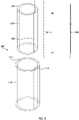
- Fig. 2 is an exploded perspective view illustrating a heat transfer tube according to a first embodiment.
- Fig. 3 is a perspective view illustrating the heat transfer tube according to the first embodiment.
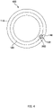
- Fig. 4 is a top view illustrating the heat transfer tube according to the first embodiment.
- a heat transfer tube 100 is a double tube having a structure capable of measuring the surface temperature of the heat transfer tube 100 using an optical fiber 200.
- the heat transfer tube 100 comprises an outer tube 110, an inner tube 120, and an insertion tube 130, to enable measurement of the surface temperature of the heat transfer tube 100 using the optical fiber 200.
- the outer tube 110 is a hollow cylindrical tube made of metal (e.g., SUS304, SUS316).
- An inner groove 112 is continuously formed, for example, by cutting, in an inner circumferential surface 111 of the outer tube 110, the inner groove 112 having, for example, a semi-cylndrical shape and extending in the longitudinal direction of the outer tube 110 from the upper opening to the lower opening of the outer tube 110.
- the inner tube 120 is a hollow cylindrical tube which is made of metal (e.g., SUS304, SUS316), and forms a double tube with the outer tube 110 such that the inner tube 120 is inserted into the outer tube 110.
- the inner tube 120 is formed of a tube containing the same metal material(s) as the outer tube 110.
- An outer groove 122 is continuously formed, for example, by cutting, in an outer circumferential surface 121 of the inner tube 120, the outer groove 122 having, for example, a semi-cylndrical shape and extending in the longitudinal direction of the inner tube 120 from the upper opening to the lower opening of the inner tube 120.
- the outer diameter of the inner tube 120 is substantially the same as the inner diameter of the outer tube 110, and is set to substantially such a diameter that the outer circumferential surface 121 of the inner tube 120 comes in close contact with the inner circumferential surface 111 of the outer tube 110 when the inner tube 120 is inserted into the outer tube 110.
- the inner tube 120 is inserted into the outer tube 110 such that the inner circumferential surface 111 and the outer circumferential surface 121 are in close contact with each other while the inner groove 112 and the outer groove 122 keep such a relative positional relationship that they face each other.
- a cylndrical insertion hole 140 is continuously formed in a region of close contact between the outer tube 110 and the inner tube 120, extending from the upper opening to the lower opening of the outer tube 110 and the inner tube 120.
- the insertion tube 130 has the same length as the outer tube 110 and the inner tube 120, and is inserted into the insertion hole 140 so as to be in close contact therewith.
- the insertion tube 130 is formed of a tube containing the same metal material(s) as the outer tube 110 and the inner tube 120.
- the optical fiber 200 is inserted into the insertion tube 130 to measure the temperature inside the insertion tube 130 as the surface temperature of the heat transfer tube 100.
- the scattering light includes Raman scattered light (Stokes light and anti-Stokes light), which is temperature-dependent, and thus the temperature of an object to be measured can be measured by detectig the Raman scattered light.
- the optical fiber 200 is inserted into the insertion tube 130, thereby being able to substantially measure the surface temperature of the heat transfer tube 100. Note that a temperature measurement method utilizing the temperature dependency of Raman scattered light is well known and thus is not described here.
- the thickness of the outer tube 110 is, for example, 1.5 mm
- the diameter of the inner groove 112 and the outer groove 122 is, for example, 0.75 mm, which corresponds to half the thickness of the outer tube 110 (the diameter of the insertion hole 140 is 1.5 mm)
- the diameter of the insertion tube 130 is, for example, slightly smaller than 1.5 mm
- the diameter of the optical fiber 200 is, for example, 0.2 mm.
- the straight tube portion of the heat transfer tube 100 is formed in units of, for example, 10 m
- the bent tube portion of the heat transfer tube 100 is formed in units of, for example, 1 m.
- the outer tube 110 and the inner tube 120 may form a double tube, for example, by shrink fitting.
- the outer tube 110 and the inner tube 120 may form a double tube such that the outer tube 110 is heated to expand, the inner tube 120 is inserted into the outer tube 110, and then the outer tube 110 is cooled to contract, to thereby bring the inner circumferential surface 111 of the outer tube 110 and the outer circumferential surface 121 of the inner tube 120 to be in close contact with each other.
- the outer tube 110 and the inner tube 120 may form a double tube, for example, by explosive bonding.
- the outer tube 110 and the inner tube 120 may form a double tube such that, after an explosive is filled in the small space between the inner circumferential surface 111 of the outer tube 110 and the outer circumferential surface 121 of the inner tube 120, the power of explosion of the explosive is used to bond the inner circumferential surface 111 of the outer tube 110 and the outer circumferential surface 121 of the inner tube 120 together.
- Fig. 5 is an exploded perspective view illustrating a heat transfer tube according to a second embodiment.
- Fig. 6 is a perspective view illustrating the heat transfer tube according to the second embodiment.
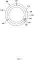
- Fig. 7 is a top view illustrating the heat transfer tube according to the second embodiment.
- a heat transfer tube 300 is a double tube having a structure capable of measuring the surface temperature of the heat transfer tube 300 using an optical fiber 200.
- the heat transfer tube 300 comprises an outer tube 310, an inner tube 320, and an insertion tube 330, to enable measurement of the surface temperature of the heat transfer tube 300 using the optical fiber 200.
- the outer tube 310 is made of metal (e.g., SUS304, SUS316) and includes a first segment portion 310A and a second segment portion 310B.
- the first segment portion 310A and the second segment portion 310B have shapes obtained by cutting the outer tube 310 into two parts along the longitudinal direction thereof.
- the first segment portion 310A is to be in close contact with a region corresponding to 2/3 of an outer circumferential surface 321 of the inner tube 320
- the second segment portion 310B is to be in close contact with the remaining region corresponding to 1/3 of the outer circumferential surface 321 of the inner tube 320.
- first segment portion 310A and the second segment portion 310B each may have a hollow semi-cylindrical shape such that they respectively come into close contact with regions each corresponding to 1/2 of the outer circumferential surface 321 of the inner tube 320.
- the first segment portion 310A and the second segment portion 310B form a hollow cylindrical shape, with an inner circumferential surface 311A of the first segment portion 310A and an inner circumferential surface 311B of the second segment portion 310B coming into close contact with the outer circumferential surface 321 of the inner tube 320.
- first segment portion 310A and the second segment portion 310B are integrally formed by welding 350 of end faces of the first segment portion 310A to end faces of the second segment portion 310B that are respectively adjacent to the end faces of the first segment portion 310A using a super heat resistant alloy (e.g., Inconel).
- An inner groove 312 is continuously formed, for example, by cutting, in the inner circumferential surface 311A of the first segment portion 310A, the inner groove 312 having, for example, a semi-cylndrical shape and extending in the longitudinal direction of the first segment portion 310A from the upper part to the lower part of the first segment portion 310A.
- the inner tube 320 is made of metal (e.g., SUS304, SUS316), has a hollow cylindrical shape, and forms a double tube with the outer tube 310 such that the inner tube 320 is surrounded by the outer tube 310.
- the inner tube 320 is formed of a tube containing the same metal material(s) as the outer tube 310.
- An outer groove 322 is continuously formed, for example, by cutting, in the outer circumferential surface 321 of the inner tube 320, the outer groove 322 having, for example, a semi-cylndrical shape and extending in the longitudinal direction of the inner tube 320 from the upper opening to the lower opening of the inner tube 320.
- the outer diameter of the inner tube 320 is substantially the same as the inner diameter of the outer tube 310, and is set to substantially such a diameter that the outer circumferential surface 321 of the inner tube 320 is in close contact with the inner circumferential surface 311 of the outer tube 310 when the inner tube 320 is surrounded by the outer tube 310.
- the outer tube 310 surrounds the inner tube 320 such that the inner circumferential surfaces 311A, 311B and the outer circumferential surface 321 are in close contact with each other while the inner groove 312 and the outer groove 322 keep such a relative positional relationship that they face each other.
- a cylndrical insertion hole 340 is formed continuously in a region of close contact between the outer tube 310 and the inner tube 320, extending from the upper opening to the lower opening of the outer tube 310 and the inner tube 320.
- the insertion tube 330 has the same length as the outer tube 310 and the inner tube 320, and is inserted into the insertion hole 340 so as to be in close contact with the insertion hole 340.
- the insertion tube 330 is formed of a tube containing the same metal material(s) as the outer tube 310 and the inner tube 320.
- the optical fiber 200 is inserted into the insertion tube 330 to measure the temperature inside the insertion tube 330 as the surface temperature of the heat transfer tube 300.
- the thickness of the outer tube 310 is, for example, 1.5 mm
- the diameter of the inner groove 312 and the outer groove 322 is, for example, 0.75 mm, which corresponds to half the thickness of the outer tube 310 (the diameter of the insertion hole 340 is 1.5 mm)
- the diameter of the insertion tube 330 is, for example, slightly smaller than 1.5 mm
- the diameter of the optical fiber 200 is, for example, 0.2 mm.
- the straight tube portion of the heat transfer tube 300 is formed in units of, for example, 10 m
- the bent tube portion of the heat transfer tube 300 is formed in units of, for example, 1 m. Then, in accordance with the size and shape of the boiler 2, the straight tube portion(s) and the bent tube portion(s) of the heat transfer tube 300 are coupled together by welding so as to continue.
- Fig. 8 is an exploded perspective view illustrating a heat transfer tube according to a third embodiment.
- Fig. 9 is a perspective view illustrating the heat transfer tube according to the third embodiment.
- Fig. 10 illustrating a top view of the heat transfer tube according to the third embodiment.
- Fig. 11 is a diagram illustrating part of a process of manufacturing the heat transfer tube according to the third embodiment.
- a heat transfer tube 600 is a double tube having a structure capable of measuring the surface temperature of the heat transfer tube 600 using an optical fiber 200.
- the heat transfer tube 600 comprises an outer tube 610, an inner tube 620, and an insertion tube 630, to enable measurement of the surface temperature of the heat transfer tube 100 using the optical fiber 200.
- the outer tube 610 is a hollow cylindrical tube made of metal (e.g., SUS304, SUS316).
- An inner groove 612 is continuously formed, for example, by cutting, in an inner circumferential surface 611 of the outer tube 610, the inner groove 612 having, for example, substantially a U-shape and extending in the longitudinal direction of the outer tube 610 from the upper opening to the lower opening of the outer tube 610.
- the inner groove 612 is a groove into which the insertion tube 630 is to be inserted.
- the inner groove 612 has an inner circumferential surface that is curved such that the outer circumferential surface of the insertion tube 630 comes into close contact with the inner groove 612 over a range of 180° or more when the insertion tube 630 is inserted thereinto.
- the inner groove 612 has such a depth that the insertion tube 630 inserted thereinto does not protrude from the inner circumferential surface 611 of the outer tube 610 when the insertion tube 630 is inserted thereinto.
- the inner groove 612 has a depth such that a tangent line to the outer circumferential surface of the insertion tube 630 comes in contact with the inner circumferential surface 611 of the outer tube 610.
- the inner tube 620 is a hollow cylindrical tube which is made of metal (e.g., SUS304, SUS316) and forms a double tube with the outer tube 610 such that the inner tube 620 is inserted into the outer tube 610.
- the inner tube 620 is formed of a tube containing the same metal material(s) as the outer tube 610.
- the outer diameter of the inner tube 620 is substantially the same as the inner diameter of the outer tube 610 and is set to substantially such a diameter that an outer circumferential surface 621 of the inner tube 620 comes into close contact with the inner circumferential surface 611 of the outer tube 610 when the inner tube 620 is inserted into the outer tube 610.
- the inner tube 620 is inserted into the outer tube 610 such that the inner circumferential surface 611 and the outer circumferential surface 621 are in close contact with each other, thereby forming a double tube from the outer tube 610 and the inner tube 620.
- the insertion tube 630 has the same length as the outer tube 610 and the inner tube 620, and is inserted so as to be in close contact with the inner circumferential surface of the inner groove 612.
- the insertion tube 630 is formed of a tube containing the same metal material(s) as the outer tube 610 and the inner tube 620.
- the optical fiber 200 is inserted into the insertion tube 630 to measure the temperature inside the insertion tube 630 as the surface temperature of the heat transfer tube 600.
- the insertion tube 630 Before the inner tube 620 is inserted into the outer tube 610, the insertion tube 630 needs to be previously attached to the inner groove 612 so as to be integral with the outer tube 610.
- the following describes an example of a process of fixing the insertion tube 630 to the inner groove 612.
- the X-axis represents a direction along the longitudinal direction of the outer tube 610
- the Y-axis represents a direction orthogonal to the longitudinal direction of the outer tube 610 (the circumferential direction of the outer tube 610)
- the Z-axis represents a direction (the thickness direction of the outer tube 610) orthogonal to both of the longitudinal direction of the outer tube 610 and the direction orthogonal to the longitudinal direction.
- the substantially U-shaped inner groove 612 is continuously formed, for exmaple, by cutting, to extend in the longitudinal direction of the outer tube 610 from the upper opening to the lower opening of the outer tube 610.
- the inner groove 612 has: an inner circumferential surface 612A to come into close contact with the outer circumferential surface of the insertion tube 630 over a range of, for example, 270°; and inner side surfaces 612B, 612C that extend in the thickness direction of the outer tube 610 respectivley from the ends of the inner circumferential surface 612A toward the inner circumferential surface 611 of the outer tube 610.
- the inner groove 612 has such a depth that a tangent line to the outer circumferential surface of the insertion tube 630 comes in contact with the inner circumferential surface 611 of the outer tube 610 ( Fig. 11A ).
- the insertion tube 630 is inserted into the inner groove 612 such that the outer circumferential surface of the insertion tube 630 comes into close contact with the inner circumferential surface 612A of the inner groove 612.
- a tangent line to the outer circumferential surface of the insertion tube 630 (indicated by the dashed dotted line) is in contact and continuous with the inner circumferential surface 611 of the outer tube 610.
- Spaces 613B, 613C are respectively formed, extending in the longitudinal direction of the outer tube 610, between the outer circumferential surface of the insertion tube 630 and the inner side surfaces 612B, 612C ( Fig. 11B ).
- stainless steel e.g., SUS304, SUS316
- SUS304, SUS316 is used to perform buildup welding to the spaces 613B, 613C
- buildups 614B, 614C are polished so as to be flush with the inner circumferential surface 611 of the outer tube 610.
- the space surrounded by the inner groove 612 and the buildups 614B, 614C corresponds to an insertion hole 640 into which the insertion tube 630 is to be inserted ( Fig. 11C ).
- the thickness of the outer tube 610 is, for example, 1.5 mm
- the diameter of the insertion tube 630 is, for example, slightly smaller than 1.5 mm
- the diameter of the optical fiber 200 is, for example, 0.2 mm.
- the straight tube portion of the heat transfer tube 600 is formed in units of, for example, 10 m
- the bent tube portion of the heat transfer tube 600 is formed in units of, for example, 1 m. Then, in accordance with the size and shape of the boiler 2, the straight tube portion(s) and the bent tube portion(s) of the heat transfer tube 600 are coupled together by welding so as to continue.
- the outer tube 610 and the inner tube 620 may form a double tube, for example, by shrink fitting. Specifically, the outer tube 610 and the inner tube 620 may form a double tube such that the outer tube 610 is heated to expand, the inner tube 620 is inserted into the outer tube 610, and then the outer tube 610 is cooled to contract such that the inner circumferential surface 611 of the outer tube 610 comes into close contact with the outer circumferential surface 621 of the inner tube 620. Also, the outer tube 610 and the inner tube 620 may form a double tube, for example, by explosive bonding.
- the outer tube 610 and the inner tube 620 may form a double tube such that, an explosive is filled in the small space between the inner circumferential surface 611 of the outer tube 610 and the outer circumferential surface 621 of the inner tube 620, and then the power of explosion of the explosive is used to bond the inner circumferential surface 611 of the outer tube 610 and the outer circumferential surface 621 of the inner tube 620 together.
- Fig. 12 is a cross-sectional diagram illustrating an example in which a bridging tube is used with the heat transfer tube according to the first or second embodiment.
- Fig. 13 is an enlarged sectional view illustrating part of the example in which a bridging tube is used with the heat transfer tubes according to the first or second embodiment.
- the optical fiber 200 which is to be passed between the two heat transfer tubes 100 (300), needs to be protected from damage caused by the welding 500.
- a bridging tube 400 is a hollow cylindrical tube made of metal (e.g., SUS304, SUS316) that joins the insertion tubes 130 (330) exposed at the opposing end faces of the two heat transfer tubes 100 (300).
- the bridging tube 400 is formed of a tube containing the same metal material (s) as the heat transfer tube 100 (300).
- the bridging tube 400 has one end to be inserted into the insertion tube 130 (330) of one of the heat transfer tubes 100 (300), and the other end to be inserted into the insertion tube 130 (330) of the other one of the heat transfer tubes 100 (300).
- the outer diameter of the bridging tube 400 is substantially the same as the inner diameter of the insertion tube 130 (330), and is set to substantially such a diameter that an outer circumferential surface 410 of the bridging tube 400 comes into close contact with an inner circumferential surface 131 (331) of the insertion tube 130 (330) when the bridging tube 400 is inserted into the insertion tube 130 (330).
- the inner diameter of the bridging tube 400 is set to such a diameter that the inner diameter thereof gradually increases from the center toward both ends of the bridging tube 400, and is substantially the same as the outer diameter of the bridging tube 400 at both ends of the bridging tube 400.
- an inner circumferential surface 420 of the bridging tube 400 is formed of a curved surface, on the whole, such that the inner circumferential surface 420 becomes gradually wider from the center toward the ends of the bridging tube 400 and smoothly continuous with the inner circumferential surfaces 131 (331) of the insertion tubes 130 (330) at the ends of the bridging tube 400.
- the thickness of the bridging tube 400 is set, with a predetermined curvature, so as to gradually descrease from the center toward the ends of the bridging tube 400 and become substantially zero at the ends of the bridging tube 400.
- the inner circumferential surface 420 of the bridging tube 400 forms such a curved surface as to be smoothly continuous with the inner circumferential surfaces 131 (331) of the insertion tubes 130 (330), thereby being able to reliably protect the optical fiber 200 from being damaged.
- joining two heat transfer tubes 100 (300) adjacent to each other using the bridging tube 400 enables coupling a plurality of heat transfer tubes 100 (300) in various shapes, such as straight and/or bent tubes, through welding, according to the size and shape of the boiler 2. That is, the surface temperature of the heat transfer tubes 100 (300) provided inside the boiler 2 can be measured in a wide area.
- the bridging tube 400 can be inserted into the insertion tubes 630 exposed from the two heat transfer tubes 600, in order to join two heat transfer tubes 600 adjacent to each other, in the third embodiment.
- a heat transfer tube 100 comprising: an outer tube 110 (310, 610); an inner tube 120 (320, 620) to be inserted into the outer tube 110 (310, 610) so as to be in close contact with the outer tube 110 (310, 610), to form a double tube with the outer tube 110 (310, 610); an insertion hole 140 (340, 640) formed, between an outer circumferential surface of the outer tube 110 (310, 610) and an inner circumferential surface of the inner tube, penetrating in a longitudinal direction of the outer tube 110 (310, 610) and the inner tube 120 (320, 620); and an insertion tube 130 (330, 630) to be inserted into the insertion hole 140 (340, 640), the insertion tube 130 (330, 630) allowing an optical fiber 200 to be inserted into the insertion tube 130 (330, 630) to measure a surface temperature of the double tube.
- the outer tube 110 (310) has an inner groove 112 (312) formed in an inner circumferential surface 111 (311A) of the outer tube 110 (310), the inner groove extending in the longitudinal direction of the outer tube 110 (310), and the inner tube 112 (312) has an outer groove 122 (322) formed in an outer circumferential surface 121 (321) of the inner tube 120 (320), the outer groove extending in the longitudinal direction of the inner tube 120 (320), the inner tube 120 (320) being inserted into the outer tube 110 (310) such that the insertion hole 140 (340) is formed with the outer groove 122 (322) facing the inner groove 112 (312).
- the inner groove 112 (312) and the outer groove 122 (322) each have a semi-cylndrical shape
- the insertion hole 140 (340) has a cylndrical shape
- the insertion tube 130 (330) has a hollow cylindrical shape.
- the outer tube 610 has the insertion hole 640 between the outer circumferential surface and an inner circumferential surface of the outer tube 610, the insertion hole extending in the longitudinal direction of the outer tube 610.
- the insertion hole 640 has a cylndrical shape
- the insertion tube 630 has a hollow cylindrical shape.
- the outer tube 110 (610) and the inner tube 120 (620) form the double tube such that the outer tube 110 (610) is heated and expanded, the inner tube 120 (620) is inserted into the outer tube 110 (610), and then the outer tube 110 (610) is cooled to bring an inner circumferential surface 111 (611) of the outer tube 110 (610) and an outer circumferential surface 112 (612) of the inner tube 120 (620) into close contact with each other.
- outer tube 110 (610) and the inner tube 120 (620) form the double tube such that an inner circumferential surface 111 (611) of the outer tube 110 (610) and an outer circumferential surface 121 (621) of the inner tube 120 (620) are coupled to each other using power of explosion of an explosive.
- the outer tube 310 has a first segment portion 310A to come into close contact with a part of an outer circumferential surface 321 of the inner tube 320, and a second segment portion 310B to come into close contact with a remaining part of the outer circumferential surface of the inner tube 320, and the outer tube 310 and the inner tube 320 form the double tube such that end faces of the first segment portion 310A and end faces of the second segment portion 310B that are respectively adjacent to the end faces of the first segment portion 310A are welded together.
- a bridging tube 400 is further comprised, which is used to weld an end face of one heat transfer tube 100 (300, 600) and an end face of another heat transfer tube 100 (300, 600), the bridging tube 400 being inserted into insertion tubes 130 (330, 630) that are respectively inserted into the one heat transfer tube and the other heat transfer tube 100 (300, 600), such that the bridging tube 400 comes in close contact with the insertion tubes 130 (330, 630).
- the bridging tube 400 has an inner circumferential surface that gradually widens toward both of the one heat transfer tube and the other heat transfer tube 100 (300, 600).
- the inner circumferential surface 420 of the bridging tube 400 has such a shape as to be continuous with respective inner circumferential surfaces 131 (331, 631) of the insertion tubes 130 (330, 630) at end faces of the bridging tube 400.
- the inner circumferential surface 420 of the bridging tube 400 has such a shape as to widen, while forming curved face, toward both of the one heat transfer tube and the other heat transfer tube 100 (300, 600).
Landscapes
- Engineering & Computer Science (AREA)
- Physics & Mathematics (AREA)
- General Physics & Mathematics (AREA)
- Mechanical Engineering (AREA)
- General Engineering & Computer Science (AREA)
- Thermal Sciences (AREA)
- Aviation & Aerospace Engineering (AREA)
- Chemical & Material Sciences (AREA)
- Combustion & Propulsion (AREA)
- Heat-Exchange Devices With Radiators And Conduit Assemblies (AREA)
- Testing Of Devices, Machine Parts, Or Other Structures Thereof (AREA)
- Measuring Temperature Or Quantity Of Heat (AREA)
Abstract
Description
- The present disclosure relates to a heat transfer tube and a method for manufacturing a heat transfer tube.
- For example, inside a power boiler in a thermal power plant, steam tubes (e.g., heat transfer tubes for a superheater, a reheater, and the like) are provided to circulate steam generated by heat exchange between water supplied from a condenser and a combustion gas. A steam tube is configured with a boiler tube made of heat-resistant steel (e.g., low-alloy steel), and if being used continuously at a high temperature exceeding design standards, the steam tube may be damaged as creep damage progresses. Thus, in order to prevent accidents caused by deterioration of the steam tube, inspections are carried out to grasp the combustion state of the boiler and the remaining life of the steam tube, based on measurement results of the surface temperature of the steam tube (see, for example, PTL 1).
- Patent Literature 1:
Japanese Patent Application Publication No.2013-190229 - To grasp the combustion state of a boiler and the remaining life of a steam tube, it is needed to measure the surface temperature of the steam tube over a wide area and obtain a temperature distribution of the surface temperature of the steam tube.
- For example, thermocouples are embedded in the surface of a steam tube at regular intervals to measure the surface temperature of the steam tube. However, in the case of using the thermocouples, the surface temperature can be measured only in a small area of the steam tube. Thus, it is difficult to obtain the temperature distribution of the surface temperature in the steam tube.
- The present disclosure is directed to provision of a heat transfer tube having a structure capable of reliably measuring the surface temperature of a steam tube and/or the like over a wide area, and also a method for manufacturing the heat transfer tube.
- An aspect of an embodiment of the present disclosure is a heat transfer tube comprising: an outer tube; an inner tube inserted into the outer tube so as to be in close contact with the outer tube, to form a double tube with the outer tube; an insertion hole formed, between an outer circumferential surface of the outer tube and an inner circumferential surface of the inner tube, penetrating in a longitudinal direction of the outer tube and the inner tube; and an insertion tube inserted into the insertion hole, the insertion tube allowing an optical fiber to be inserted into the insertion tube to measure a surface temperature of the double tube.
- Other features of the present disclosure will become apparent from the description in the present specification and the accompanying drawings.
- According to the present disclosure, it is possible to reliably measure the surface temperature of a steam tube and/or the like over a wide area.
-
-
Fig. 1 is a diagram illustrating an example of an overall configuration of a thermal power plant in which a heat transfer tube according to an embodiment of the present disclosure is used as a steam tube. -
Fig. 2 is an exploded perspective view illustrating a heat transfer tube according to a first embodiment. -
Fig. 3 is a perspective view illustrating a heat transfer tube according to a first embodiment. -
Fig. 4 is a top view illustrating a heat transfer tube according to a first embodiment. -
Fig. 5 is an exploded perspective view illustrating a heat transfer tube according to a second embodiment. -
Fig. 6 is a perspective view illustrating a heat transfer tube according to a second embodiment. -
Fig. 7 is a top view illustrating a heat transfer tube according to a second embodiment. -
Fig. 8 is an exploded perspective view illustrating a heat transfer tube according to a third embodiment. -
Fig. 9 is a perspective view illustrating a heat transfer tube according to a third embodiment. -
Fig. 10 is a top view illustrating a heat transfer tube according to a third embodiment. -
Fig. 11 is a diagram illustrating part of a process of manufacturing a heat transfer tube according to a third embodiment. -
Fig. 12 is a cross-sectional view illustrating an example in which a bridging tube is used with heat transfer tubes according to a first or second embodiment. -
Fig. 13 is an enlarged cross-sectional view illustrating part of an example in which a bridging tube is used with heat transfer tubes according to a first or second embodiment. - At least the following matters will be apparent from the description of the specification and the attached drawings.
-
Fig. 1 is a diagram illustrating an example of an overall configuration of a thermal power plant in which a heat transfer tube according to an embodiment of the present disclosure is used as a steam tube. - A
thermal power plant 1 comprises aboiler 2, a steam generator 3, awater wall 4, asteam valve 5, a high-pressure turbine 6, an intermediate-pressure turbine 7, a low-pressure turbine 8, areheater 9, acondenser 10, afeed pump 11, and apower generator 12. - The
boiler 2 is a heat exchanger that mixes an externally-supplied fuel (e.g., pulverized coal) with air to generate a combustion gas, and transforms water into vapor using the heat of the combustion gas. Theboiler 2 houses the steam generator 3, thewater wall 4, and thereheater 9. The steam generator 3 comprises an economizer (not shown) that preheats water supplied from thecondenser 10, and a superheater (not shown) that additionally heats saturated steam supplied from thewater wall 4, to convert the saturated steam into superheated steam. Thewater wall 4 forms the housing of theboiler 2, and turns the preheated water into the saturated steam and supplies the saturated steam to the superheater. Thesteam valve 5 is a regulating valve that controls the flow rate of the superheated steam generated by the steam generator 3. - The high-
pressure turbine 6, the intermediate-pressure turbine 7, and the low-pressure turbine 8 share the same single rotatingshaft 13, which is coupled to the rotating shaft of thepower generator 12. Upon being supplied with the superheated steam (first steam) generated by the steam generator 3, via thesteam valve 5, the high-pressure turbine 6 expands the first steam and supplies the expanded steam (second steam) to thereheater 9 in theboiler 2. Thereheater 9 reheats the second steam, and supplies the reheated steam (third steam) to the intermediate-pressure turbine 7. The intermediate-pressure turbine 7 expands the third steam, and supplies the expanded steam (fourth steam) to the low-pressure turbine 8. The low-pressure turbine 8 expands the fourth steam. - The
condenser 10 condenses the gas exhausted after the low-pressure turbine 8 expands the fourth steam, thereby converting the exhaust gas into condensate. Thefeed pump 11 raises the pressure of the condensate generated by thecondenser 10, and supplies the condensate to the steam generator 3 in theboiler 2 as feed water. - Then, to generate power, the
power generator 12 is driven by the power generated when the fourth steam is expanded. - A heat transfer tube according to an embodiment of the present disclosure is used to form a superheater tube (steam tube) configuring the superheater in the steam generator 3 and a reheater tube (steam tube) configuring the
reheater 9 in order to measure the surface temperatures of the superheater tube and the reheater tube. Details will be given later. Note that, for convenience of explanation, the superheater tube and the reheater tube are hereinafter referred to as heat transfer tubes 100 (300). -
Fig. 2 is an exploded perspective view illustrating a heat transfer tube according to a first embodiment.Fig. 3 is a perspective view illustrating the heat transfer tube according to the first embodiment.Fig. 4 is a top view illustrating the heat transfer tube according to the first embodiment. - A
heat transfer tube 100 is a double tube having a structure capable of measuring the surface temperature of theheat transfer tube 100 using anoptical fiber 200. - The
heat transfer tube 100 comprises anouter tube 110, aninner tube 120, and aninsertion tube 130, to enable measurement of the surface temperature of theheat transfer tube 100 using theoptical fiber 200. - The
outer tube 110 is a hollow cylindrical tube made of metal (e.g., SUS304, SUS316). Aninner groove 112 is continuously formed, for example, by cutting, in an innercircumferential surface 111 of theouter tube 110, theinner groove 112 having, for example, a semi-cylndrical shape and extending in the longitudinal direction of theouter tube 110 from the upper opening to the lower opening of theouter tube 110. - The
inner tube 120 is a hollow cylindrical tube which is made of metal (e.g., SUS304, SUS316), and forms a double tube with theouter tube 110 such that theinner tube 120 is inserted into theouter tube 110. Theinner tube 120 is formed of a tube containing the same metal material(s) as theouter tube 110. Anouter groove 122 is continuously formed, for example, by cutting, in an outercircumferential surface 121 of theinner tube 120, theouter groove 122 having, for example, a semi-cylndrical shape and extending in the longitudinal direction of theinner tube 120 from the upper opening to the lower opening of theinner tube 120. The outer diameter of theinner tube 120 is substantially the same as the inner diameter of theouter tube 110, and is set to substantially such a diameter that the outercircumferential surface 121 of theinner tube 120 comes in close contact with the innercircumferential surface 111 of theouter tube 110 when theinner tube 120 is inserted into theouter tube 110. - The
inner tube 120 is inserted into theouter tube 110 such that the innercircumferential surface 111 and the outercircumferential surface 121 are in close contact with each other while theinner groove 112 and theouter groove 122 keep such a relative positional relationship that they face each other. This forms a double tube from theouter tube 110 and theinner tube 120. With theinner groove 112 and theouter groove 122 facing each other, acylndrical insertion hole 140 is continuously formed in a region of close contact between theouter tube 110 and theinner tube 120, extending from the upper opening to the lower opening of theouter tube 110 and theinner tube 120. - The
insertion tube 130 has the same length as theouter tube 110 and theinner tube 120, and is inserted into theinsertion hole 140 so as to be in close contact therewith. Theinsertion tube 130 is formed of a tube containing the same metal material(s) as theouter tube 110 and theinner tube 120. Theoptical fiber 200 is inserted into theinsertion tube 130 to measure the temperature inside theinsertion tube 130 as the surface temperature of theheat transfer tube 100. - When pulsed light enters the
optical fiber 200, the pulsed light travels while slightly scattering inside theoptical fiber 200. The scattering light includes Raman scattered light (Stokes light and anti-Stokes light), which is temperature-dependent, and thus the temperature of an object to be measured can be measured by detectig the Raman scattered light. In other words, theoptical fiber 200 is inserted into theinsertion tube 130, thereby being able to substantially measure the surface temperature of theheat transfer tube 100. Note that a temperature measurement method utilizing the temperature dependency of Raman scattered light is well known and thus is not described here. - It is assumed in the first embodiment that the thickness of the
outer tube 110 is, for example, 1.5 mm, the diameter of theinner groove 112 and theouter groove 122 is, for example, 0.75 mm, which corresponds to half the thickness of the outer tube 110 (the diameter of theinsertion hole 140 is 1.5 mm), the diameter of theinsertion tube 130 is, for example, slightly smaller than 1.5 mm, and the diameter of theoptical fiber 200 is, for example, 0.2 mm. The straight tube portion of theheat transfer tube 100 is formed in units of, for example, 10 m, and the bent tube portion of theheat transfer tube 100 is formed in units of, for example, 1 m. Then, in accordance with the size and the shape of theboiler 2, the straight tube portion(s) and the bent tube portion(s) of theheat transfer tube 100 are coupled together by welding so as to continue. - The
outer tube 110 and theinner tube 120 may form a double tube, for example, by shrink fitting. Specifically, theouter tube 110 and theinner tube 120 may form a double tube such that theouter tube 110 is heated to expand, theinner tube 120 is inserted into theouter tube 110, and then theouter tube 110 is cooled to contract, to thereby bring the innercircumferential surface 111 of theouter tube 110 and the outercircumferential surface 121 of theinner tube 120 to be in close contact with each other. Also, theouter tube 110 and theinner tube 120 may form a double tube, for example, by explosive bonding. Specifically, theouter tube 110 and theinner tube 120 may form a double tube such that, after an explosive is filled in the small space between the innercircumferential surface 111 of theouter tube 110 and the outercircumferential surface 121 of theinner tube 120, the power of explosion of the explosive is used to bond the innercircumferential surface 111 of theouter tube 110 and the outercircumferential surface 121 of theinner tube 120 together. -
Fig. 5 is an exploded perspective view illustrating a heat transfer tube according to a second embodiment.Fig. 6 is a perspective view illustrating the heat transfer tube according to the second embodiment.Fig. 7 is a top view illustrating the heat transfer tube according to the second embodiment. - A
heat transfer tube 300 is a double tube having a structure capable of measuring the surface temperature of theheat transfer tube 300 using anoptical fiber 200. - The
heat transfer tube 300 comprises anouter tube 310, aninner tube 320, and aninsertion tube 330, to enable measurement of the surface temperature of theheat transfer tube 300 using theoptical fiber 200. - The
outer tube 310 is made of metal (e.g., SUS304, SUS316) and includes afirst segment portion 310A and asecond segment portion 310B. Thefirst segment portion 310A and thesecond segment portion 310B have shapes obtained by cutting theouter tube 310 into two parts along the longitudinal direction thereof. In an embodiment of the present disclsoure, thefirst segment portion 310A is to be in close contact with a region corresponding to 2/3 of an outercircumferential surface 321 of theinner tube 320, and thesecond segment portion 310B is to be in close contact with the remaining region corresponding to 1/3 of the outercircumferential surface 321 of theinner tube 320. Alternatively, thefirst segment portion 310A and thesecond segment portion 310B each may have a hollow semi-cylindrical shape such that they respectively come into close contact with regions each corresponding to 1/2 of the outercircumferential surface 321 of theinner tube 320. Thefirst segment portion 310A and thesecond segment portion 310B form a hollow cylindrical shape, with an innercircumferential surface 311A of thefirst segment portion 310A and an innercircumferential surface 311B of thesecond segment portion 310B coming into close contact with the outercircumferential surface 321 of theinner tube 320. And, thefirst segment portion 310A and thesecond segment portion 310B are integrally formed by welding 350 of end faces of thefirst segment portion 310A to end faces of thesecond segment portion 310B that are respectively adjacent to the end faces of thefirst segment portion 310A using a super heat resistant alloy (e.g., Inconel). Aninner groove 312 is continuously formed, for example, by cutting, in the innercircumferential surface 311A of thefirst segment portion 310A, theinner groove 312 having, for example, a semi-cylndrical shape and extending in the longitudinal direction of thefirst segment portion 310A from the upper part to the lower part of thefirst segment portion 310A. - The
inner tube 320 is made of metal (e.g., SUS304, SUS316), has a hollow cylindrical shape, and forms a double tube with theouter tube 310 such that theinner tube 320 is surrounded by theouter tube 310. Theinner tube 320 is formed of a tube containing the same metal material(s) as theouter tube 310. Anouter groove 322 is continuously formed, for example, by cutting, in the outercircumferential surface 321 of theinner tube 320, theouter groove 322 having, for example, a semi-cylndrical shape and extending in the longitudinal direction of theinner tube 320 from the upper opening to the lower opening of theinner tube 320. The outer diameter of theinner tube 320 is substantially the same as the inner diameter of theouter tube 310, and is set to substantially such a diameter that the outercircumferential surface 321 of theinner tube 320 is in close contact with the inner circumferential surface 311 of theouter tube 310 when theinner tube 320 is surrounded by theouter tube 310. - The
outer tube 310 surrounds theinner tube 320 such that the innercircumferential surfaces circumferential surface 321 are in close contact with each other while theinner groove 312 and theouter groove 322 keep such a relative positional relationship that they face each other. This forms a double tube from theouter tube 310 and theinner tube 320. With theinner groove 312 and theouter groove 322 facing each other, acylndrical insertion hole 340 is formed continuously in a region of close contact between theouter tube 310 and theinner tube 320, extending from the upper opening to the lower opening of theouter tube 310 and theinner tube 320. - The
insertion tube 330 has the same length as theouter tube 310 and theinner tube 320, and is inserted into theinsertion hole 340 so as to be in close contact with theinsertion hole 340. Theinsertion tube 330 is formed of a tube containing the same metal material(s) as theouter tube 310 and theinner tube 320. Theoptical fiber 200 is inserted into theinsertion tube 330 to measure the temperature inside theinsertion tube 330 as the surface temperature of theheat transfer tube 300. - It is assumed in the second embodiment that the thickness of the
outer tube 310 is, for example, 1.5 mm, the diameter of theinner groove 312 and theouter groove 322 is, for example, 0.75 mm, which corresponds to half the thickness of the outer tube 310 (the diameter of theinsertion hole 340 is 1.5 mm), the diameter of theinsertion tube 330 is, for example, slightly smaller than 1.5 mm, and the diameter of theoptical fiber 200 is, for example, 0.2 mm. The straight tube portion of theheat transfer tube 300 is formed in units of, for example, 10 m, and the bent tube portion of theheat transfer tube 300 is formed in units of, for example, 1 m. Then, in accordance with the size and shape of theboiler 2, the straight tube portion(s) and the bent tube portion(s) of theheat transfer tube 300 are coupled together by welding so as to continue. -
Fig. 8 is an exploded perspective view illustrating a heat transfer tube according to a third embodiment.Fig. 9 is a perspective view illustrating the heat transfer tube according to the third embodiment.Fig. 10 illustrating a top view of the heat transfer tube according to the third embodiment.Fig. 11 is a diagram illustrating part of a process of manufacturing the heat transfer tube according to the third embodiment. - A
heat transfer tube 600 is a double tube having a structure capable of measuring the surface temperature of theheat transfer tube 600 using anoptical fiber 200. - The
heat transfer tube 600 comprises anouter tube 610, aninner tube 620, and aninsertion tube 630, to enable measurement of the surface temperature of theheat transfer tube 100 using theoptical fiber 200. - The
outer tube 610 is a hollow cylindrical tube made of metal (e.g., SUS304, SUS316). Aninner groove 612 is continuously formed, for example, by cutting, in an innercircumferential surface 611 of theouter tube 610, theinner groove 612 having, for example, substantially a U-shape and extending in the longitudinal direction of theouter tube 610 from the upper opening to the lower opening of theouter tube 610. Theinner groove 612 is a groove into which theinsertion tube 630 is to be inserted. Theinner groove 612 has an inner circumferential surface that is curved such that the outer circumferential surface of theinsertion tube 630 comes into close contact with theinner groove 612 over a range of 180° or more when theinsertion tube 630 is inserted thereinto. Also, theinner groove 612 has such a depth that theinsertion tube 630 inserted thereinto does not protrude from the innercircumferential surface 611 of theouter tube 610 when theinsertion tube 630 is inserted thereinto. For example, theinner groove 612 has a depth such that a tangent line to the outer circumferential surface of theinsertion tube 630 comes in contact with the innercircumferential surface 611 of theouter tube 610. - The
inner tube 620 is a hollow cylindrical tube which is made of metal (e.g., SUS304, SUS316) and forms a double tube with theouter tube 610 such that theinner tube 620 is inserted into theouter tube 610. Theinner tube 620 is formed of a tube containing the same metal material(s) as theouter tube 610. The outer diameter of theinner tube 620 is substantially the same as the inner diameter of theouter tube 610 and is set to substantially such a diameter that an outercircumferential surface 621 of theinner tube 620 comes into close contact with the innercircumferential surface 611 of theouter tube 610 when theinner tube 620 is inserted into theouter tube 610. - Then, the
inner tube 620 is inserted into theouter tube 610 such that the innercircumferential surface 611 and the outercircumferential surface 621 are in close contact with each other, thereby forming a double tube from theouter tube 610 and theinner tube 620. - The
insertion tube 630 has the same length as theouter tube 610 and theinner tube 620, and is inserted so as to be in close contact with the inner circumferential surface of theinner groove 612. Theinsertion tube 630 is formed of a tube containing the same metal material(s) as theouter tube 610 and theinner tube 620. Theoptical fiber 200 is inserted into theinsertion tube 630 to measure the temperature inside theinsertion tube 630 as the surface temperature of theheat transfer tube 600. - Before the
inner tube 620 is inserted into theouter tube 610, theinsertion tube 630 needs to be previously attached to theinner groove 612 so as to be integral with theouter tube 610. With reference toFig. 11 , the following describes an example of a process of fixing theinsertion tube 630 to theinner groove 612. Note that, inFig. 11 , the X-axis represents a direction along the longitudinal direction of theouter tube 610, the Y-axis represents a direction orthogonal to the longitudinal direction of the outer tube 610 (the circumferential direction of the outer tube 610), and the Z-axis represents a direction (the thickness direction of the outer tube 610) orthogonal to both of the longitudinal direction of theouter tube 610 and the direction orthogonal to the longitudinal direction. - First, the substantially U-shaped
inner groove 612 is continuously formed, for exmaple, by cutting, to extend in the longitudinal direction of theouter tube 610 from the upper opening to the lower opening of theouter tube 610. Theinner groove 612 has: an innercircumferential surface 612A to come into close contact with the outer circumferential surface of theinsertion tube 630 over a range of, for example, 270°; and inner side surfaces 612B, 612C that extend in the thickness direction of theouter tube 610 respectivley from the ends of the innercircumferential surface 612A toward the innercircumferential surface 611 of theouter tube 610. Also, theinner groove 612 has such a depth that a tangent line to the outer circumferential surface of theinsertion tube 630 comes in contact with the innercircumferential surface 611 of the outer tube 610 (Fig. 11A ). - Next, the
insertion tube 630 is inserted into theinner groove 612 such that the outer circumferential surface of theinsertion tube 630 comes into close contact with the innercircumferential surface 612A of theinner groove 612. In this state, a tangent line to the outer circumferential surface of the insertion tube 630 (indicated by the dashed dotted line) is in contact and continuous with the innercircumferential surface 611 of theouter tube 610.Spaces outer tube 610, between the outer circumferential surface of theinsertion tube 630 and the inner side surfaces 612B, 612C (Fig. 11B ). - Next, stainless steel (e.g., SUS304, SUS316) is used to perform buildup welding to the
spaces circumferential surface 611 of theouter tube 610. This fixes theinsertion tube 630 to theouter tube 610 at a position closest to theinner tube 620 that forms a double tube together with theouter tube 610. Note that the space surrounded by theinner groove 612 and thebuildups insertion hole 640 into which theinsertion tube 630 is to be inserted (Fig. 11C ). - It is assumed in the third embodiment that the thickness of the
outer tube 610 is, for example, 1.5 mm, the diameter of theinsertion tube 630 is, for example, slightly smaller than 1.5 mm, and the diameter of theoptical fiber 200 is, for example, 0.2 mm. Also, the straight tube portion of theheat transfer tube 600 is formed in units of, for example, 10 m, and the bent tube portion of theheat transfer tube 600 is formed in units of, for example, 1 m. Then, in accordance with the size and shape of theboiler 2, the straight tube portion(s) and the bent tube portion(s) of theheat transfer tube 600 are coupled together by welding so as to continue. - The
outer tube 610 and theinner tube 620 may form a double tube, for example, by shrink fitting. Specifically, theouter tube 610 and theinner tube 620 may form a double tube such that theouter tube 610 is heated to expand, theinner tube 620 is inserted into theouter tube 610, and then theouter tube 610 is cooled to contract such that the innercircumferential surface 611 of theouter tube 610 comes into close contact with the outercircumferential surface 621 of theinner tube 620. Also, theouter tube 610 and theinner tube 620 may form a double tube, for example, by explosive bonding. Specifically, theouter tube 610 and theinner tube 620 may form a double tube such that, an explosive is filled in the small space between the innercircumferential surface 611 of theouter tube 610 and the outercircumferential surface 621 of theinner tube 620, and then the power of explosion of the explosive is used to bond the innercircumferential surface 611 of theouter tube 610 and the outercircumferential surface 621 of theinner tube 620 together. -
Fig. 12 is a cross-sectional diagram illustrating an example in which a bridging tube is used with the heat transfer tube according to the first or second embodiment.Fig. 13 is an enlarged sectional view illustrating part of the example in which a bridging tube is used with the heat transfer tubes according to the first or second embodiment. - In a case where opposing end faces of two heat transfer tubes 100 (300) are coupled to each other by welding 500, the
optical fiber 200, which is to be passed between the two heat transfer tubes 100 (300), needs to be protected from damage caused by thewelding 500. - A bridging
tube 400 is a hollow cylindrical tube made of metal (e.g., SUS304, SUS316) that joins the insertion tubes 130 (330) exposed at the opposing end faces of the two heat transfer tubes 100 (300). The bridgingtube 400 is formed of a tube containing the same metal material (s) as the heat transfer tube 100 (300). The bridgingtube 400 has one end to be inserted into the insertion tube 130 (330) of one of the heat transfer tubes 100 (300), and the other end to be inserted into the insertion tube 130 (330) of the other one of the heat transfer tubes 100 (300). The outer diameter of the bridgingtube 400 is substantially the same as the inner diameter of the insertion tube 130 (330), and is set to substantially such a diameter that an outercircumferential surface 410 of the bridgingtube 400 comes into close contact with an inner circumferential surface 131 (331) of the insertion tube 130 (330) when the bridgingtube 400 is inserted into the insertion tube 130 (330). In addition, the inner diameter of the bridgingtube 400 is set to such a diameter that the inner diameter thereof gradually increases from the center toward both ends of the bridgingtube 400, and is substantially the same as the outer diameter of the bridgingtube 400 at both ends of the bridgingtube 400. In other words, an innercircumferential surface 420 of the bridgingtube 400 is formed of a curved surface, on the whole, such that the innercircumferential surface 420 becomes gradually wider from the center toward the ends of the bridgingtube 400 and smoothly continuous with the inner circumferential surfaces 131 (331) of the insertion tubes 130 (330) at the ends of the bridgingtube 400. In yet other words, the thickness of the bridgingtube 400 is set, with a predetermined curvature, so as to gradually descrease from the center toward the ends of the bridgingtube 400 and become substantially zero at the ends of the bridgingtube 400. - As such, inserting the bridging
tube 400 between the insertion tubes 130 (330) exposed at the opposing end faces of the two heat transfer tubes 100 (300) before welding the opposing end faces of the two heat transfer tubes 100 (300) makes it possible to relialy ensure formation of a path for continuously inserting theoptical fiber 200 into the two heat transfer tubes 100 (300). In addition, the innercircumferential surface 420 of the bridgingtube 400 forms such a curved surface as to be smoothly continuous with the inner circumferential surfaces 131 (331) of the insertion tubes 130 (330), thereby being able to reliably protect theoptical fiber 200 from being damaged. In addition, joining two heat transfer tubes 100 (300) adjacent to each other using thebridging tube 400 enables coupling a plurality of heat transfer tubes 100 (300) in various shapes, such as straight and/or bent tubes, through welding, according to the size and shape of theboiler 2. That is, the surface temperature of the heat transfer tubes 100 (300) provided inside theboiler 2 can be measured in a wide area. - Note that the bridging
tube 400 can be inserted into theinsertion tubes 630 exposed from the twoheat transfer tubes 600, in order to join twoheat transfer tubes 600 adjacent to each other, in the third embodiment. - As has been described hereinabove, a heat transfer tube 100 (300, 600) comprising: an outer tube 110 (310, 610); an inner tube 120 (320, 620) to be inserted into the outer tube 110 (310, 610) so as to be in close contact with the outer tube 110 (310, 610), to form a double tube with the outer tube 110 (310, 610); an insertion hole 140 (340, 640) formed, between an outer circumferential surface of the outer tube 110 (310, 610) and an inner circumferential surface of the inner tube, penetrating in a longitudinal direction of the outer tube 110 (310, 610) and the inner tube 120 (320, 620); and an insertion tube 130 (330, 630) to be inserted into the insertion hole 140 (340, 640), the insertion tube 130 (330, 630) allowing an
optical fiber 200 to be inserted into the insertion tube 130 (330, 630) to measure a surface temperature of the double tube. - In addition, the outer tube 110 (310) has an inner groove 112 (312) formed in an inner circumferential surface 111 (311A) of the outer tube 110 (310), the inner groove extending in the longitudinal direction of the outer tube 110 (310), and the inner tube 112 (312) has an outer groove 122 (322) formed in an outer circumferential surface 121 (321) of the inner tube 120 (320), the outer groove extending in the longitudinal direction of the inner tube 120 (320), the inner tube 120 (320) being inserted into the outer tube 110 (310) such that the insertion hole 140 (340) is formed with the outer groove 122 (322) facing the inner groove 112 (312). For example, the inner groove 112 (312) and the outer groove 122 (322) each have a semi-cylndrical shape, the insertion hole 140 (340) has a cylndrical shape, and the insertion tube 130 (330) has a hollow cylindrical shape.
- In addition, the
outer tube 610 has theinsertion hole 640 between the outer circumferential surface and an inner circumferential surface of theouter tube 610, the insertion hole extending in the longitudinal direction of theouter tube 610. For example, theinsertion hole 640 has a cylndrical shape, and theinsertion tube 630 has a hollow cylindrical shape. - In addition, the outer tube 110 (610) and the inner tube 120 (620) form the double tube such that the outer tube 110 (610) is heated and expanded, the inner tube 120 (620) is inserted into the outer tube 110 (610), and then the outer tube 110 (610) is cooled to bring an inner circumferential surface 111 (611) of the outer tube 110 (610) and an outer circumferential surface 112 (612) of the inner tube 120 (620) into close contact with each other.
- In addition, the outer tube 110 (610) and the inner tube 120 (620) form the double tube such that an inner circumferential surface 111 (611) of the outer tube 110 (610) and an outer circumferential surface 121 (621) of the inner tube 120 (620) are coupled to each other using power of explosion of an explosive.
- In addition, the
outer tube 310 has afirst segment portion 310A to come into close contact with a part of an outercircumferential surface 321 of theinner tube 320, and asecond segment portion 310B to come into close contact with a remaining part of the outer circumferential surface of theinner tube 320, and theouter tube 310 and theinner tube 320 form the double tube such that end faces of thefirst segment portion 310A and end faces of thesecond segment portion 310B that are respectively adjacent to the end faces of thefirst segment portion 310A are welded together. - In addition, a bridging
tube 400 is further comprised, which is used to weld an end face of one heat transfer tube 100 (300, 600) and an end face of another heat transfer tube 100 (300, 600), the bridgingtube 400 being inserted into insertion tubes 130 (330, 630) that are respectively inserted into the one heat transfer tube and the other heat transfer tube 100 (300, 600), such that the bridgingtube 400 comes in close contact with the insertion tubes 130 (330, 630). - In addition, the bridging
tube 400 has an inner circumferential surface that gradually widens toward both of the one heat transfer tube and the other heat transfer tube 100 (300, 600). - In addition, the inner
circumferential surface 420 of the bridgingtube 400 has such a shape as to be continuous with respective inner circumferential surfaces 131 (331, 631) of the insertion tubes 130 (330, 630) at end faces of the bridgingtube 400. - In addition, the inner
circumferential surface 420 of the bridgingtube 400 has such a shape as to widen, while forming curved face, toward both of the one heat transfer tube and the other heat transfer tube 100 (300, 600). - According to an embodiment of the present disclosure, it is possible to measure, over a wide area, a surface temperature of the heat transfer tube 100 (300, 600) provided in a
boiler 2. - Embodiments of the present disclosure described above are simply to facilitate understanding of the present disclosure and are not in any way to be construed as limiting the present disclosure. The present disclosure may variously be changed or altered without departing from its essential features and encompass equivalents thereof.
-
- 100, 300, 600 heat transfer tube
- 110, 310, 610 outer tube
- 111, 311A, 420, 611, 612A inner circumferential surface
- 112, 312, 612 inner groove
- 120, 320, 620 inner tube
- 121, 321, 410, 621 outer circumferential surface
- 122, 322, 622 outer groove
- 130, 330, 630 insertion tube
- 140, 340, 640 insertion hole
- 200 optical fiber
- 350, 500 welding
- 400 bridging tube
- 612B, 612C inner side surface
- 613B, 613C space
- 614B, 614C buildup
Claims (16)
- A heat transfer tube comprising:an outer tube;an inner tube inserted into the outer tube so as to be in close contact with the outer tube, to form a double tube with the outer tube;an insertion hole formed, between an outer circumferential surface of the outer tube and an inner circumferential surface of the inner tube, penetrating in a longitudinal direction of the outer tube and the inner tube; andan insertion tube inserted into the insertion hole, the insertion tube allowing an optical fiber to be inserted into the insertion tube to measure a surface temperature of the double tube.
- The heat transfer tube according to claim 1, whereinthe outer tube has an inner groove formed in an inner circumferential surface of the outer tube, the inner groove extending in the longitudinal direction of the outer tube, andthe inner tube has an outer groove formed in an outer circumferential surface of the inner tube, the outer groove extending in the longitudinal direction of the inner tube, the inner tube being inserted into the outer tube such that the insertion hole is formed with the outer groove facing the inner groove.
- The heat transfer tube according to claim 2, whereinthe inner groove and the outer groove each have a semi-cylndrical shape,the insertion hole has a cylndrical shape, andthe insertion tube has a hollow cylindrical shape.
- The heat transfer tube according to claim 1, wherein
the outer tube has the insertion hole between the outer circumferential surface and an inner circumferential surface of the outer tube, the insertion hole extending in the longitudinal direction of the outer tube. - The heat transfer tube according to claim 4, whereinthe insertion hole has a cylndrical shape, andthe insertion tube has a hollow cylindrical shape.
- The heat transfer tube according to any one of claims 1 to 5, wherein the outer tube and the inner tube form the double tube such that the outer tube is heated and expanded, the inner tube is inserted into the outer tube, and then the outer tube is cooled to bring an inner circumferential surface of the outer tube and an outer circumferential surface of the inner tube into close contact with each other.
- The heat transfer tube according to any one of claims 1 to 5, wherein the outer tube and the inner tube form the double tube such that an inner circumferential surface of the outer tube and an outer circumferential surface of the inner tube are coupled to each other using power of explosion of an explosive.
- The heat transfer tube according to any one of claims 1 to 5, whereinthe outer tube hasa first segment portion to come into close contact with a part of an outer circumferential surface of the inner tube, anda second segment portion to come into close contact with a remaining part of the outer circumferential surface of the inner tube, andthe outer tube and the inner tube form the double tube such that end faces of the first segment portion and end faces of the second segment portion that are respectively adjacent to the end faces of the first segment portion are welded together.
- The heat transfer tube according to any one of claims 1 to 8, further comprising
a bridging tube used to weld an end face of one double tube and an end face of another double tube, the bridging tube being inserted into insertion tubes that are respectively inserted into the one double tube and the other double tube, such that the bridging tube comes in close contact with the insertion tubes, the one double tube and the other double tube each being the double tube, the insertion tubes each being the insertion tube. - The heat transfer tube according to claim 9, wherein the bridging tube has an inner circumferential surface that gradually widens toward both of the one double tube and the other double tube.
- The heat transfer tube according to claim 10, wherein the inner circumferential surface of the bridging tube is continuous with respective inner circumferential surfaces of the insertion tubes at end faces of the bridging tube.
- The heat transfer tube according to claim 10 or 11, wherein the inner circumferential surface of the bridging tube widens, while forming curved face, toward both of the one double tube and the other double tube.
- A method for manufacturing a heat transfer tube comprising:a first step of inserting an inner tube into an outer tube such that the outer tube comes in close contact with the inner tube, so as to form a double tube from the outer tube and the inner tube;a second step of forming an insertion hole, between an outer circumferential surface of the outer tube and an inner circumferential surface of the inner tube, penetrating in a longitudinal direction of the outer tube and the inner tube; anda third step of inserting, into the insertion hole, an insertion tube allowing an optical fiber to be inserted into the insertion tube to measure a surface temperature of the double tube.
- The method for manufacturing a heat transfer tube according to claim 13, whereinthe first step is inserting the inner tube into the outer tube such that an inner circumferential surface of the outer tube and an outer circumferential surface of the inner tube come into close contact with each other to form the double tube from the outer tube and the inner tube,the second step is, when inserting the inner tube into the outer tube, causing an inner groove that is formed in the inner circumferential surface of the outer tube and that extends in the longitudinal direction of the outer tube, and an outer groove that is formed in the outer circumferential surface of the inner tube and that extends in the longitudinal direction of the inner tube to face each other, to form the insertion hole, andthe third step is inserting the insertion tube into the insertion hole after inserting the inner tube into the outer tube.
- The method for manufacturing a heat transfer tube according to claim 13, whereinthe first step is inserting the inner tube into the outer tube such that an inner circumferential surface of the outer tube and an outer circumferential surface of the inner tube come in close contact with each other, to form the double tube from the outer tube and the inner tube,the second step is, before inserting the inner tube into the outer tube, forming the insertion hole between an inner circumferential surface and the outer circumferential surface of the outer tube, the insertion hole penetrating in the longitudinal direction of the outer tube, andthe third step is inserting the insertion tube into the insertion hole after inserting the inner tube into the outer tube.
- The method for manufacturing a heat transfer tube according to claim 15, wherein
the second step includesforming an inner groove that is to be in contact with an outer circumferential surface of the insertion tube, the inner groove extending in the longitudinal direction of the outer tube andbuilding up a metal material in a space between the inner groove and the insertion tube after inserting the insertion tube into the inner groove, such that the built-up metal material is flush with the inner circumferential surface of the outer tube.
Applications Claiming Priority (1)
| Application Number | Priority Date | Filing Date | Title |
|---|---|---|---|
| PCT/JP2019/028750 WO2021014549A1 (en) | 2019-07-23 | 2019-07-23 | Heat transfer pipe and method for manufacturing heat transfer pipe |
Publications (3)
| Publication Number | Publication Date |
|---|---|
| EP4006416A1 true EP4006416A1 (en) | 2022-06-01 |
| EP4006416A4 EP4006416A4 (en) | 2022-08-10 |
| EP4006416B1 EP4006416B1 (en) | 2023-09-06 |
Family
ID=70000571
Family Applications (1)
| Application Number | Title | Priority Date | Filing Date |
|---|---|---|---|
| EP19938682.2A Active EP4006416B1 (en) | 2019-07-23 | 2019-07-23 | Heat transfer pipe and method for manufacturing heat transfer pipe |
Country Status (4)
| Country | Link |
|---|---|
| US (1) | US20220244109A1 (en) |
| EP (1) | EP4006416B1 (en) |
| JP (1) | JP6669323B1 (en) |
| WO (1) | WO2021014549A1 (en) |
Families Citing this family (1)
| Publication number | Priority date | Publication date | Assignee | Title |
|---|---|---|---|---|
| WO2021220534A1 (en) * | 2020-05-01 | 2021-11-04 | 株式会社Eサーモジェンテック | Tube-type heat exchanger with thermoelectric power generation function, manufacturing method thereof, and thermoelectric power generation apparatus using same |
Family Cites Families (20)
| Publication number | Priority date | Publication date | Assignee | Title |
|---|---|---|---|---|
| IT1164308B (en) * | 1983-07-07 | 1987-04-08 | Cise Spa | INSTRUMENTED TUBULAR ELEMENT WITH TEMPERATURE SENSORS, IN PARTICULAR FOR THE DETECTION OF OVERTEMPERATURES IN THE PIPES OF THE HEATERS OF THERMOELECTRIC POWER STATIONS |
| WO1991003337A1 (en) * | 1989-09-01 | 1991-03-21 | Ube Industries, Ltd. | Method of manufacturing metallic mold having heating cooling pipe incorporated |
| JPH049651A (en) * | 1990-04-25 | 1992-01-14 | Sumitomo Electric Ind Ltd | Fluid transport pipe liquid leak detection method |
| JPH0518848A (en) * | 1991-07-09 | 1993-01-26 | Toshiba Corp | Leak-detection device |
| JP2595856B2 (en) * | 1992-01-30 | 1997-04-02 | 住友金属工業株式会社 | Manufacturing method of seamless clad metal tube |
| GB9302903D0 (en) * | 1993-02-13 | 1993-03-31 | Univ Strathclyde | Detection system |
| JPH0798254A (en) * | 1993-09-30 | 1995-04-11 | Toshiba Corp | measuring device |
| US5551484A (en) * | 1994-08-19 | 1996-09-03 | Charboneau; Kenneth R. | Pipe liner and monitoring system |
| US5921285A (en) * | 1995-09-28 | 1999-07-13 | Fiberspar Spoolable Products, Inc. | Composite spoolable tube |
| US6004639A (en) * | 1997-10-10 | 1999-12-21 | Fiberspar Spoolable Products, Inc. | Composite spoolable tube with sensor |
| US6220079B1 (en) * | 1998-07-22 | 2001-04-24 | Safety Liner Systems, L.L.C. | Annular fluid manipulation in lined tubular systems |
| US6935376B1 (en) * | 1998-07-28 | 2005-08-30 | Safetyliner Systems, Llc | Enhancement of profiled tubular lining systems by channel augmentation |
| US6305427B1 (en) * | 1999-11-19 | 2001-10-23 | Kenway Corporation | Double walled apparatus and methods |
| US8839822B2 (en) * | 2006-03-22 | 2014-09-23 | National Oilwell Varco, L.P. | Dual containment systems, methods and kits |
| JP4940191B2 (en) * | 2008-07-04 | 2012-05-30 | 日立Geニュークリア・エナジー株式会社 | Steam generator |
| US20130068340A1 (en) * | 2011-09-15 | 2013-03-21 | Tyco Thermal Controls, Llc | Heat trace system including hybrid composite insulation |
| JP5497085B2 (en) | 2012-03-12 | 2014-05-21 | 中国電力株式会社 | Tube leak inspection apparatus and tube leak inspection method |
| CN103727521A (en) * | 2014-01-20 | 2014-04-16 | 河南华润电力首阳山有限公司 | Temperature-measuring element fixing device and boiler |
| JP6251941B2 (en) * | 2014-08-19 | 2017-12-27 | 三菱日立パワーシステムズ株式会社 | boiler |
| BR112017007900A2 (en) * | 2014-11-25 | 2018-01-23 | Halliburton Energy Services Inc | tubular element, subsea tubular transport, and methods of manufacturing and installing a tubular element. |
-
2019
- 2019-07-23 WO PCT/JP2019/028750 patent/WO2021014549A1/en not_active Ceased
- 2019-07-23 EP EP19938682.2A patent/EP4006416B1/en active Active
- 2019-07-23 JP JP2019560413A patent/JP6669323B1/en active Active
- 2019-07-23 US US17/629,082 patent/US20220244109A1/en not_active Abandoned
Also Published As
| Publication number | Publication date |
|---|---|
| US20220244109A1 (en) | 2022-08-04 |
| WO2021014549A1 (en) | 2021-01-28 |
| JPWO2021014549A1 (en) | 2021-09-13 |
| EP4006416A4 (en) | 2022-08-10 |
| JP6669323B1 (en) | 2020-03-18 |
| EP4006416B1 (en) | 2023-09-06 |
Similar Documents
| Publication | Publication Date | Title |
|---|---|---|
| KR101233555B1 (en) | Welded header/nozzle structure | |
| EP4006416B1 (en) | Heat transfer pipe and method for manufacturing heat transfer pipe | |
| CN102714068B (en) | There is the prelum of the Surge line piping adapter hot jacket cylinder of mechanical attachment | |
| JP4293789B2 (en) | Composite tube, manufacturing method thereof, and fluid transfer method | |
| EP0572265B1 (en) | Heat exchanger unit for heat recovery steam generator | |
| US20090035092A1 (en) | Screw for Use in Thermally Loaded Surroundings | |
| JP4637435B2 (en) | Turbine equipment | |
| JP6551621B1 (en) | Steam pipe temperature measuring device, steam pipe temperature measuring method | |
| KR20220015333A (en) | Heat exchanger with inner sensor grid and restraints for sensor wires and heat exchange tubes | |
| US7487745B2 (en) | Boiler tube position retainer assembly | |
| JP6651722B2 (en) | Piping fatigue test method | |
| CN112443372A (en) | Temperature regulation of exhaust assembly | |
| WO2021157141A1 (en) | Thermometer protective cylinder, temperature measurement instrument, steam pipe structure, and method for installing thermometer protective cylinder | |
| EP2423473B1 (en) | An improved organic rankine cycle system and method | |
| US20190170022A1 (en) | Components and systems for reducing thermal stress of heat recovery steam generators in combined cycle power plant systems | |
| EP3055613B1 (en) | Thermal device, its use, and method for heating a heat transfer medium | |
| WO2020054011A1 (en) | Steam-pipe temperature measurement device, steam-pipe temperature measurement method | |
| Dzierwa | New start-up curves for a 200 MW steam boiler with natural circulation | |
| US11859911B2 (en) | Coaxial heat transfer tube suitable for a fluidized bed boiler and a method for manufacturing same | |
| EP1684011B1 (en) | Steam generator | |
| JP6953564B2 (en) | Plug and steam piping structure and how to install the plug | |
| ES2909185T3 (en) | Arrangement of tubes and furnace | |
| JP2003139400A (en) | Heat exchange equipment | |
| JP2002122484A (en) | Tube surface temperature measuring device | |
| WO2019230608A1 (en) | Creep life evaluation method |
Legal Events
| Date | Code | Title | Description |
|---|---|---|---|
| STAA | Information on the status of an ep patent application or granted ep patent |
Free format text: STATUS: THE INTERNATIONAL PUBLICATION HAS BEEN MADE |
|
| PUAI | Public reference made under article 153(3) epc to a published international application that has entered the european phase |
Free format text: ORIGINAL CODE: 0009012 |
|
| STAA | Information on the status of an ep patent application or granted ep patent |
Free format text: STATUS: REQUEST FOR EXAMINATION WAS MADE |
|
| 17P | Request for examination filed |
Effective date: 20220202 |
|
| AK | Designated contracting states |
Kind code of ref document: A1 Designated state(s): AL AT BE BG CH CY CZ DE DK EE ES FI FR GB GR HR HU IE IS IT LI LT LU LV MC MK MT NL NO PL PT RO RS SE SI SK SM TR |
|
| A4 | Supplementary search report drawn up and despatched |
Effective date: 20220707 |
|
| RIC1 | Information provided on ipc code assigned before grant |
Ipc: G01M 99/00 20110101ALI20220701BHEP Ipc: F28F 1/00 20060101ALI20220701BHEP Ipc: F22B 37/38 20060101AFI20220701BHEP |
|
| DAV | Request for validation of the european patent (deleted) | ||
| DAX | Request for extension of the european patent (deleted) | ||
| GRAP | Despatch of communication of intention to grant a patent |
Free format text: ORIGINAL CODE: EPIDOSNIGR1 |
|
| STAA | Information on the status of an ep patent application or granted ep patent |
Free format text: STATUS: GRANT OF PATENT IS INTENDED |
|
| INTG | Intention to grant announced |
Effective date: 20230321 |
|
| GRAS | Grant fee paid |
Free format text: ORIGINAL CODE: EPIDOSNIGR3 |
|
| GRAA | (expected) grant |
Free format text: ORIGINAL CODE: 0009210 |
|
| STAA | Information on the status of an ep patent application or granted ep patent |
Free format text: STATUS: THE PATENT HAS BEEN GRANTED |
|
| AK | Designated contracting states |
Kind code of ref document: B1 Designated state(s): AL AT BE BG CH CY CZ DE DK EE ES FI FR GB GR HR HU IE IS IT LI LT LU LV MC MK MT NL NO PL PT RO RS SE SI SK SM TR |
|
| REG | Reference to a national code |
Ref country code: GB Ref legal event code: FG4D |
|
| REG | Reference to a national code |
Ref country code: CH Ref legal event code: EP |
|
| REG | Reference to a national code |
Ref country code: IE Ref legal event code: FG4D |
|
| REG | Reference to a national code |
Ref country code: DE Ref legal event code: R096 Ref document number: 602019037171 Country of ref document: DE |
|
| REG | Reference to a national code |
Ref country code: LT Ref legal event code: MG9D |
|
| REG | Reference to a national code |
Ref country code: NL Ref legal event code: MP Effective date: 20230906 |
|
| PG25 | Lapsed in a contracting state [announced via postgrant information from national office to epo] |
Ref country code: GR Free format text: LAPSE BECAUSE OF FAILURE TO SUBMIT A TRANSLATION OF THE DESCRIPTION OR TO PAY THE FEE WITHIN THE PRESCRIBED TIME-LIMIT Effective date: 20231207 |
|
| PG25 | Lapsed in a contracting state [announced via postgrant information from national office to epo] |
Ref country code: SE Free format text: LAPSE BECAUSE OF FAILURE TO SUBMIT A TRANSLATION OF THE DESCRIPTION OR TO PAY THE FEE WITHIN THE PRESCRIBED TIME-LIMIT Effective date: 20230906 Ref country code: RS Free format text: LAPSE BECAUSE OF FAILURE TO SUBMIT A TRANSLATION OF THE DESCRIPTION OR TO PAY THE FEE WITHIN THE PRESCRIBED TIME-LIMIT Effective date: 20230906 Ref country code: NO Free format text: LAPSE BECAUSE OF FAILURE TO SUBMIT A TRANSLATION OF THE DESCRIPTION OR TO PAY THE FEE WITHIN THE PRESCRIBED TIME-LIMIT Effective date: 20231206 Ref country code: LV Free format text: LAPSE BECAUSE OF FAILURE TO SUBMIT A TRANSLATION OF THE DESCRIPTION OR TO PAY THE FEE WITHIN THE PRESCRIBED TIME-LIMIT Effective date: 20230906 Ref country code: LT Free format text: LAPSE BECAUSE OF FAILURE TO SUBMIT A TRANSLATION OF THE DESCRIPTION OR TO PAY THE FEE WITHIN THE PRESCRIBED TIME-LIMIT Effective date: 20230906 Ref country code: HR Free format text: LAPSE BECAUSE OF FAILURE TO SUBMIT A TRANSLATION OF THE DESCRIPTION OR TO PAY THE FEE WITHIN THE PRESCRIBED TIME-LIMIT Effective date: 20230906 Ref country code: GR Free format text: LAPSE BECAUSE OF FAILURE TO SUBMIT A TRANSLATION OF THE DESCRIPTION OR TO PAY THE FEE WITHIN THE PRESCRIBED TIME-LIMIT Effective date: 20231207 Ref country code: FI Free format text: LAPSE BECAUSE OF FAILURE TO SUBMIT A TRANSLATION OF THE DESCRIPTION OR TO PAY THE FEE WITHIN THE PRESCRIBED TIME-LIMIT Effective date: 20230906 |
|
| REG | Reference to a national code |
Ref country code: AT Ref legal event code: MK05 Ref document number: 1608987 Country of ref document: AT Kind code of ref document: T Effective date: 20230906 |
|
| PG25 | Lapsed in a contracting state [announced via postgrant information from national office to epo] |
Ref country code: NL Free format text: LAPSE BECAUSE OF FAILURE TO SUBMIT A TRANSLATION OF THE DESCRIPTION OR TO PAY THE FEE WITHIN THE PRESCRIBED TIME-LIMIT Effective date: 20230906 |
|
| PG25 | Lapsed in a contracting state [announced via postgrant information from national office to epo] |
Ref country code: IS Free format text: LAPSE BECAUSE OF FAILURE TO SUBMIT A TRANSLATION OF THE DESCRIPTION OR TO PAY THE FEE WITHIN THE PRESCRIBED TIME-LIMIT Effective date: 20240106 |
|
| PG25 | Lapsed in a contracting state [announced via postgrant information from national office to epo] |
Ref country code: AT Free format text: LAPSE BECAUSE OF FAILURE TO SUBMIT A TRANSLATION OF THE DESCRIPTION OR TO PAY THE FEE WITHIN THE PRESCRIBED TIME-LIMIT Effective date: 20230906 |
|
| PG25 | Lapsed in a contracting state [announced via postgrant information from national office to epo] |
Ref country code: ES Free format text: LAPSE BECAUSE OF FAILURE TO SUBMIT A TRANSLATION OF THE DESCRIPTION OR TO PAY THE FEE WITHIN THE PRESCRIBED TIME-LIMIT Effective date: 20230906 |
|
| PG25 | Lapsed in a contracting state [announced via postgrant information from national office to epo] |
Ref country code: SM Free format text: LAPSE BECAUSE OF FAILURE TO SUBMIT A TRANSLATION OF THE DESCRIPTION OR TO PAY THE FEE WITHIN THE PRESCRIBED TIME-LIMIT Effective date: 20230906 Ref country code: RO Free format text: LAPSE BECAUSE OF FAILURE TO SUBMIT A TRANSLATION OF THE DESCRIPTION OR TO PAY THE FEE WITHIN THE PRESCRIBED TIME-LIMIT Effective date: 20230906 Ref country code: IS Free format text: LAPSE BECAUSE OF FAILURE TO SUBMIT A TRANSLATION OF THE DESCRIPTION OR TO PAY THE FEE WITHIN THE PRESCRIBED TIME-LIMIT Effective date: 20240106 Ref country code: ES Free format text: LAPSE BECAUSE OF FAILURE TO SUBMIT A TRANSLATION OF THE DESCRIPTION OR TO PAY THE FEE WITHIN THE PRESCRIBED TIME-LIMIT Effective date: 20230906 Ref country code: EE Free format text: LAPSE BECAUSE OF FAILURE TO SUBMIT A TRANSLATION OF THE DESCRIPTION OR TO PAY THE FEE WITHIN THE PRESCRIBED TIME-LIMIT Effective date: 20230906 Ref country code: CZ Free format text: LAPSE BECAUSE OF FAILURE TO SUBMIT A TRANSLATION OF THE DESCRIPTION OR TO PAY THE FEE WITHIN THE PRESCRIBED TIME-LIMIT Effective date: 20230906 Ref country code: AT Free format text: LAPSE BECAUSE OF FAILURE TO SUBMIT A TRANSLATION OF THE DESCRIPTION OR TO PAY THE FEE WITHIN THE PRESCRIBED TIME-LIMIT Effective date: 20230906 Ref country code: PT Free format text: LAPSE BECAUSE OF FAILURE TO SUBMIT A TRANSLATION OF THE DESCRIPTION OR TO PAY THE FEE WITHIN THE PRESCRIBED TIME-LIMIT Effective date: 20240108 Ref country code: SK Free format text: LAPSE BECAUSE OF FAILURE TO SUBMIT A TRANSLATION OF THE DESCRIPTION OR TO PAY THE FEE WITHIN THE PRESCRIBED TIME-LIMIT Effective date: 20230906 |
|
| PG25 | Lapsed in a contracting state [announced via postgrant information from national office to epo] |
Ref country code: PL Free format text: LAPSE BECAUSE OF FAILURE TO SUBMIT A TRANSLATION OF THE DESCRIPTION OR TO PAY THE FEE WITHIN THE PRESCRIBED TIME-LIMIT Effective date: 20230906 |
|
| REG | Reference to a national code |
Ref country code: DE Ref legal event code: R097 Ref document number: 602019037171 Country of ref document: DE |
|
| PG25 | Lapsed in a contracting state [announced via postgrant information from national office to epo] |
Ref country code: DK Free format text: LAPSE BECAUSE OF FAILURE TO SUBMIT A TRANSLATION OF THE DESCRIPTION OR TO PAY THE FEE WITHIN THE PRESCRIBED TIME-LIMIT Effective date: 20230906 |
|
| PLBE | No opposition filed within time limit |
Free format text: ORIGINAL CODE: 0009261 |
|
| STAA | Information on the status of an ep patent application or granted ep patent |
Free format text: STATUS: NO OPPOSITION FILED WITHIN TIME LIMIT |
|
| PG25 | Lapsed in a contracting state [announced via postgrant information from national office to epo] |
Ref country code: DK Free format text: LAPSE BECAUSE OF FAILURE TO SUBMIT A TRANSLATION OF THE DESCRIPTION OR TO PAY THE FEE WITHIN THE PRESCRIBED TIME-LIMIT Effective date: 20230906 Ref country code: SI Free format text: LAPSE BECAUSE OF FAILURE TO SUBMIT A TRANSLATION OF THE DESCRIPTION OR TO PAY THE FEE WITHIN THE PRESCRIBED TIME-LIMIT Effective date: 20230906 |
|
| 26N | No opposition filed |
Effective date: 20240607 |
|
| PG25 | Lapsed in a contracting state [announced via postgrant information from national office to epo] |
Ref country code: BG Free format text: LAPSE BECAUSE OF FAILURE TO SUBMIT A TRANSLATION OF THE DESCRIPTION OR TO PAY THE FEE WITHIN THE PRESCRIBED TIME-LIMIT Effective date: 20230906 |
|
| PG25 | Lapsed in a contracting state [announced via postgrant information from national office to epo] |
Ref country code: BG Free format text: LAPSE BECAUSE OF FAILURE TO SUBMIT A TRANSLATION OF THE DESCRIPTION OR TO PAY THE FEE WITHIN THE PRESCRIBED TIME-LIMIT Effective date: 20230906 |
|
| REG | Reference to a national code |
Ref country code: DE Ref legal event code: R119 Ref document number: 602019037171 Country of ref document: DE |
|
| PG25 | Lapsed in a contracting state [announced via postgrant information from national office to epo] |
Ref country code: MC Free format text: LAPSE BECAUSE OF FAILURE TO SUBMIT A TRANSLATION OF THE DESCRIPTION OR TO PAY THE FEE WITHIN THE PRESCRIBED TIME-LIMIT Effective date: 20230906 |
|
| REG | Reference to a national code |
Ref country code: CH Ref legal event code: PL |
|
| PG25 | Lapsed in a contracting state [announced via postgrant information from national office to epo] |
Ref country code: LU Free format text: LAPSE BECAUSE OF NON-PAYMENT OF DUE FEES Effective date: 20240723 |
|
| GBPC | Gb: european patent ceased through non-payment of renewal fee |
Effective date: 20240723 |
|
| PG25 | Lapsed in a contracting state [announced via postgrant information from national office to epo] |
Ref country code: LU Free format text: LAPSE BECAUSE OF NON-PAYMENT OF DUE FEES Effective date: 20240723 |
|
| PG25 | Lapsed in a contracting state [announced via postgrant information from national office to epo] |
Ref country code: DE Free format text: LAPSE BECAUSE OF NON-PAYMENT OF DUE FEES Effective date: 20250201 |
|
| PG25 | Lapsed in a contracting state [announced via postgrant information from national office to epo] |
Ref country code: CH Free format text: LAPSE BECAUSE OF NON-PAYMENT OF DUE FEES Effective date: 20240731 Ref country code: BE Free format text: LAPSE BECAUSE OF NON-PAYMENT OF DUE FEES Effective date: 20240731 |
|
| PG25 | Lapsed in a contracting state [announced via postgrant information from national office to epo] |
Ref country code: FR Free format text: LAPSE BECAUSE OF NON-PAYMENT OF DUE FEES Effective date: 20240731 |
|
| PG25 | Lapsed in a contracting state [announced via postgrant information from national office to epo] |
Ref country code: GB Free format text: LAPSE BECAUSE OF NON-PAYMENT OF DUE FEES Effective date: 20240723 |
|
| REG | Reference to a national code |
Ref country code: BE Ref legal event code: MM Effective date: 20240731 |
|
| PG25 | Lapsed in a contracting state [announced via postgrant information from national office to epo] |
Ref country code: IT Free format text: LAPSE BECAUSE OF NON-PAYMENT OF DUE FEES Effective date: 20240723 |
|
| PG25 | Lapsed in a contracting state [announced via postgrant information from national office to epo] |
Ref country code: IE Free format text: LAPSE BECAUSE OF NON-PAYMENT OF DUE FEES Effective date: 20240723 |
|
| PG25 | Lapsed in a contracting state [announced via postgrant information from national office to epo] |
Ref country code: CY Free format text: LAPSE BECAUSE OF FAILURE TO SUBMIT A TRANSLATION OF THE DESCRIPTION OR TO PAY THE FEE WITHIN THE PRESCRIBED TIME-LIMIT; INVALID AB INITIO Effective date: 20190723 |
|
| PG25 | Lapsed in a contracting state [announced via postgrant information from national office to epo] |
Ref country code: HU Free format text: LAPSE BECAUSE OF FAILURE TO SUBMIT A TRANSLATION OF THE DESCRIPTION OR TO PAY THE FEE WITHIN THE PRESCRIBED TIME-LIMIT; INVALID AB INITIO Effective date: 20190723 |