EP4006346A2 - Rotary compressor and refrigeration apparatus - Google Patents
Rotary compressor and refrigeration apparatus Download PDFInfo
- Publication number
- EP4006346A2 EP4006346A2 EP21209445.2A EP21209445A EP4006346A2 EP 4006346 A2 EP4006346 A2 EP 4006346A2 EP 21209445 A EP21209445 A EP 21209445A EP 4006346 A2 EP4006346 A2 EP 4006346A2
- Authority
- EP
- European Patent Office
- Prior art keywords
- cylinder
- cylinder chamber
- compressor
- blade
- press
- Prior art date
- Legal status (The legal status is an assumption and is not a legal conclusion. Google has not performed a legal analysis and makes no representation as to the accuracy of the status listed.)
- Granted
Links
Images



Classifications
-
- F—MECHANICAL ENGINEERING; LIGHTING; HEATING; WEAPONS; BLASTING
- F04—POSITIVE - DISPLACEMENT MACHINES FOR LIQUIDS; PUMPS FOR LIQUIDS OR ELASTIC FLUIDS
- F04C—ROTARY-PISTON, OR OSCILLATING-PISTON, POSITIVE-DISPLACEMENT MACHINES FOR LIQUIDS; ROTARY-PISTON, OR OSCILLATING-PISTON, POSITIVE-DISPLACEMENT PUMPS
- F04C18/00—Rotary-piston pumps specially adapted for elastic fluids
- F04C18/30—Rotary-piston pumps specially adapted for elastic fluids having the characteristics covered by two or more of groups F04C18/02, F04C18/08, F04C18/22, F04C18/24, F04C18/48, or having the characteristics covered by one of these groups together with some other type of movement between co-operating members
- F04C18/32—Rotary-piston pumps specially adapted for elastic fluids having the characteristics covered by two or more of groups F04C18/02, F04C18/08, F04C18/22, F04C18/24, F04C18/48, or having the characteristics covered by one of these groups together with some other type of movement between co-operating members having both the movement defined in group F04C18/02 and relative reciprocation between the co-operating members
- F04C18/322—Rotary-piston pumps specially adapted for elastic fluids having the characteristics covered by two or more of groups F04C18/02, F04C18/08, F04C18/22, F04C18/24, F04C18/48, or having the characteristics covered by one of these groups together with some other type of movement between co-operating members having both the movement defined in group F04C18/02 and relative reciprocation between the co-operating members with vanes hinged to the outer member and reciprocating with respect to the outer member
-
- F—MECHANICAL ENGINEERING; LIGHTING; HEATING; WEAPONS; BLASTING
- F04—POSITIVE - DISPLACEMENT MACHINES FOR LIQUIDS; PUMPS FOR LIQUIDS OR ELASTIC FLUIDS
- F04C—ROTARY-PISTON, OR OSCILLATING-PISTON, POSITIVE-DISPLACEMENT MACHINES FOR LIQUIDS; ROTARY-PISTON, OR OSCILLATING-PISTON, POSITIVE-DISPLACEMENT PUMPS
- F04C29/00—Component parts, details or accessories of pumps or pumping installations, not provided for in groups F04C18/00 - F04C28/00
- F04C29/12—Arrangements for admission or discharge of the working fluid, e.g. constructional features of the inlet or outlet
- F04C29/124—Arrangements for admission or discharge of the working fluid, e.g. constructional features of the inlet or outlet with inlet and outlet valves specially adapted for rotary or oscillating piston pumps
-
- F—MECHANICAL ENGINEERING; LIGHTING; HEATING; WEAPONS; BLASTING
- F04—POSITIVE - DISPLACEMENT MACHINES FOR LIQUIDS; PUMPS FOR LIQUIDS OR ELASTIC FLUIDS
- F04C—ROTARY-PISTON, OR OSCILLATING-PISTON, POSITIVE-DISPLACEMENT MACHINES FOR LIQUIDS; ROTARY-PISTON, OR OSCILLATING-PISTON, POSITIVE-DISPLACEMENT PUMPS
- F04C2240/00—Components
- F04C2240/80—Other components
- F04C2240/806—Pipes for fluids; Fittings therefor
-
- F—MECHANICAL ENGINEERING; LIGHTING; HEATING; WEAPONS; BLASTING
- F04—POSITIVE - DISPLACEMENT MACHINES FOR LIQUIDS; PUMPS FOR LIQUIDS OR ELASTIC FLUIDS
- F04C—ROTARY-PISTON, OR OSCILLATING-PISTON, POSITIVE-DISPLACEMENT MACHINES FOR LIQUIDS; ROTARY-PISTON, OR OSCILLATING-PISTON, POSITIVE-DISPLACEMENT PUMPS
- F04C2250/00—Geometry
Definitions
- the present disclosure relates to compressors and a refrigeration apparatuses.
- a compressor has a cylinder provided with a suction passage.
- a suction pipe is attached to the suction passage via a connection member (see, for example, JP H6-213183 A (Patent Literature 1)).
- connection member In the compressor, an end portion of the connection member is press-fitted and fixed to the suction passage of the cylinder.
- the end portion (the press-fitting portion) of the connection member is expanded. Therefore, there is a problem of deformation of a blade hole in the cylinder. This causes abnormal wear or seizure of the blade to occur in the compressor.
- the present disclosure proposes a compressor capable of suppressing deformation of a blade hole, and a refrigeration apparatus including the compressor.
- a compressor of the present disclosure includes:
- the distance from the center point of the cylinder chamber to the press-fitting portion is set to be equal to or longer than the distance to the radially outer end of the blade hole, whereby deformation of the blade hole in the cylinder can be suppressed when the press-fitting portion of the pipe connection member is press-fitted into the suction passage of the cylinder.
- the suction passage communicates with the high pressure side region of the cylinder chamber, and a refrigerant from the pipe connection member is supplied to the high pressure side region of the cylinder chamber via the suction passage.
- an intermediate-pressure refrigerant is introduced into the high pressure side region of the cylinder chamber via the suction passage, whereby refrigerating capacity can be improved.
- the compressor according to one aspect of the present disclosure includes a valve structure that is installed in the suction passage and regulates a flow of a refrigerant from the high pressure side region of the cylinder chamber toward the pipe connection member.
- the valve structure installed in the suction passage restricts the flow of the refrigerant from the high pressure side region of the cylinder chamber toward the pipe connection member between the pipe connection member and the cylinder chamber. This can prevent the refrigerant from flowing back from the compressor side via the suction passage.
- a ratio R2/R1 of the distance from the center point of the cylinder chamber to the press-fitting portion to the distance from the center point of the cylinder chamber to the radially outer end of the blade hole is 1.02 or more.
- a refrigeration apparatus includes any one of the above compressors.
- the compressor capable of suppressing deformation of the blade hole in the cylinder to thereby suppress the occurrence of abnormal wear and seizure of the blade is used, whereby a highly reliable refrigeration apparatus can be realized.
- FIG. 1 is a configuration diagram of a refrigerant circuit of an air conditioner including a compressor 21 according to a first embodiment of the present disclosure.
- This air conditioner is an example of a refrigeration apparatus.
- reference numeral 13 denotes an indoor fan that causes indoor air to flow to an indoor heat exchanger 12
- reference numeral 28 denotes an outdoor fan that causes outside air to flow to an outdoor heat exchanger 23.
- the air conditioner includes an indoor unit 1 and an outdoor unit 2 connected via a part of a refrigerant circuit RC.
- the indoor unit 1 includes the indoor heat exchanger 12, the indoor fan 13, and the like.
- the outdoor unit 2 includes the outdoor heat exchanger 23, the outdoor fan 28, and the like.
- the refrigerant circuit RC is filled with a refrigerant that circulates to achieve a refrigeration cycle.
- the compressor 21, a four-way switching valve 22, the outdoor heat exchanger 23, an outdoor expansion valve 24, a gas-liquid separator 25, an indoor expansion valve 11, and the indoor heat exchanger 12 are annularly connected to the refrigerant circuit RC.
- the refrigerant circuit RC are configure so that refrigerant discharged from the compressor 21 return to the compressor 21 through the four-way switching valve 22, the outdoor heat exchanger 23, the outdoor expansion valve 24, the gas-liquid separator 25, the indoor expansion valve 11, and the indoor heat exchanger 12.
- a first port P1 of the four-way switching valve 22 is connected to a discharge side of the compressor 21 via a discharge pipe L1.
- a second port P2 of the four-way switching valve 22 is connected to a first suction port 110 (illustrated in FIGS. 2 and 3 ) of the compressor 21 via a suction pipe L4.
- a third port P3 of the four-way switching valve 22 is connected to one end of the outdoor heat exchanger 23.
- a fourth port P4 of the four-way switching valve 22 is connected to one end of the indoor heat exchanger 12.
- the inside of the gas-liquid separator 25 is connected to one end of an intermediate injection pipe L2, and the other end of the intermediate injection pipe L2 is connected to one end of an intermediate electromagnetic valve 26.
- the other end of the intermediate electromagnetic valve 26 is connected to one end of an intermediate pipe L3, and the other end of the intermediate pipe L3 is connected to a second suction port 120 (illustrated in FIGS. 2 and 3 ) of the compressor 21.
- the intermediate pipe L3 is connected to one end of a suction communication pipe L5, and the other end of the suction communication pipe L5 is connected to the suction pipe L4 of the compressor 21.
- the suction communication pipe L5A is provided with a suction electromagnetic valve 27 that is an on-off valve.
- the four-way switching valve 22 is in a first state (a state indicated by a broken line in FIG. 1 ), and the first port P1 and the third port P3 communicate with each other, and at the same time, the second port P2 and the fourth port P4 communicate with each other.
- the refrigerant compressed by the compressor 21 is condensed by the outdoor heat exchanger 23, decompressed by the indoor expansion valve 11, and evaporated by the indoor heat exchanger 12.
- the four-way switching valve 22 is in a second state (a state indicated by a solid line in FIG. 1 ), the first port P1 and the fourth port P4 communicate with each other, and at the same time, the second port P2 and the third port P3 communicate with each other.
- the refrigerant compressed by the compressor 21 is condensed by the indoor heat exchanger 12, decompressed by the outdoor expansion valve 24, and evaporated by the outdoor heat exchanger 23.
- an injection operation for introducing an intermediate-pressure refrigerant into a high pressure side region in the compressor 21 is performed.
- the intermediate electromagnetic valve 26 is opened and the suction electromagnetic valve 27 is closed.
- the intermediate-pressure refrigerant in the gas-liquid separator 25 is introduced into the intermediate pipe L3 of the compressor 21 through the intermediate injection pipe L2.
- the intermediate electromagnetic valve 26 is closed and the suction electromagnetic valve 27 is opened.
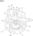
- FIG. 2 is a top plan view of a cylinder 101 and a swing member 102 of the compressor 21.
- a cylinder chamber 103 defined by an inner peripheral surface 101a is formed in the cylinder 101.
- the compressor 21 includes the swing member 102 swinging in the cylinder 101.
- the swing member 102 has a piston 102a housed in the cylinder chamber 103 and a blade 102b integrally formed with the piston 102a.
- the inside of the cylinder chamber 103 is partitioned by the piston 102a and the blade 102b.
- a suction chamber 103a (low pressure side region) is formed on the right side of the piston 102a and the blade 102b
- a compression chamber 103b high pressure side region
- the piston 102a and the blade 102b partition the cylinder chamber 103 into the high pressure side region and the low pressure side region, respectively.
- the first suction port 110 penetrating in the radial direction is formed on the right side (suction chamber 103a side) of the blade 102b in the cylinder 101.
- the first suction port 110 opens to the suction chamber 103a on the right side of the blade 102b.
- the suction pipe L4 (illustrated in FIG. 1 ) is connected to the first suction port 110 from the outside.
- the second suction port 120 penetrating in the radial direction is formed on the left side (compression chamber 103b side) of the blade 102b in the cylinder 101.
- the second suction port 120 opens to the compression chamber 103b on the left side of the blade 102b.
- a pipe connection member 200 is connected to the second suction port 120 from the outside.
- the second suction port 120 is an example of a suction passage.
- a press-fitting portion 201b (illustrated in FIG. 3 ) of the pipe connection member 200 is press-fitted into the second suction port 120 (suction passage) from a radially outer side of the cylinder 101.
- the intermediate pipe L3 (illustrated in FIG. 1 ) is connected to the pipe connection member 200 from the outside.
- the intermediate pipe L3 (illustrated in FIG. 1 ) is connected to the pipe connection member 200 by welding from the outside.
- a blade hole 104 of the cylinder 101 is a bush hole provided in the cylinder 101 in continuation with the cylinder chamber 103.
- a pair of swinging bushings 105,105 are disposed in the blade hole 104.
- Lubricating oil lubricates between the blade 102b and the swinging bushings 105,105. These swinging bushings 105, 105 sandwich the blade 102b from both sides, thereby support the blade 102b so as to be able to advance and retract. The blade 102b protrudes into and retracts from a back surface space 106 provided in the cylinder 101.
- a shaft 140 has an eccentric portion 150 disposed in the cylinder chamber 103.
- the eccentric portion 150 is provided so as to be eccentric with respect to a center axis of the shaft 140.
- the eccentric portion 150 eccentrically rotates, and the piston 102a fitted to the eccentric portion 150 turns along the inner peripheral surface 101a of the cylinder chamber 103.
- the piston 102a revolves in the cylinder chamber 103, low-pressure refrigerant gas is sucked into the suction chamber 103a from the first suction port 110 and compressed into a high pressure in the compression chamber 103b, and thereafter, the high-pressure refrigerant gas is discharged from a discharge port 130 (illustrated in FIG. 3 ).
- the intermediate-pressure refrigerant is introduced from the second suction port 120 into the compression chamber 103b. Thereafter, the refrigerant gas discharged from the discharge port 130 is exhausted from the discharge pipe L1 of the compressor 21.
- FIG. 3 is a cross-sectional view of the cylinder 101 taken along a plane orthogonal to the shaft 140 (illustrated in FIG. 2 ).
- reference numeral 130 denotes a discharge port formed on the left side (compression chamber 103b side) of the blade 102b in the cylinder 101.
- An intermediate pipe L3 (illustrated in FIG. 1 ) is connected to an inflow end of the second suction port 120 (radially outer side of the cylinder 101).
- An outflow end of the second suction port 120 (radially inner side of the cylinder 101) opens to the compression chamber 103b of the cylinder chamber 103.
- the intermediate pipe L3 and the compression chamber 103b communicate with each other via the second suction port 120.
- the refrigerant is guided to the cylinder chamber 103 through the second suction port 120 extending from the outer peripheral surface of the cylinder 101 to the inner peripheral surface 101a of the cylinder 101.
- a straight line x passes through a center point O1 and O2.
- the center point O2 lies halfway between two ends of the inner peripheral surface 101a of the cylinder chamber 103.
- the two ends are continuous with the blade hole 104. That is, the two ends are border between the blade hole 104 and the inner peripheral surface 101a of the cylinder chamber 103.
- the straight line x intersects a center axis y of the second suction port 120 (suction passage) at an angle ⁇ (for example, 25 deg).
- the pipe connection member 200 press-fitted into the second suction port 120 (suction passage) from the radially outer side of the cylinder 101 has a cylindrical body 201, an annular valve body 202, and an annular valve seat 203.
- the cylindrical body 201 includes a flange portion 201a, the press-fitting portion 201b, and a valve pressing portion 201c in this order from the radially outer side of the cylinder 101.
- the valve pressing portion 201c has a plurality of through holes 201d penetrating in the axial direction.
- the plurality of through holes 201d are annularly arranged around the center axis y of the second suction port 120.
- the valve pressing portion 201c of the cylindrical body 201, the valve body 202, and the valve seat 203 constitute a valve structure 210 for opening and closing the second suction port 120.
- the valve structure 210 is located between a radially outer end of the pipe connection member 200 and the cylinder chamber 103.
- the valve structure 210 including the valve pressing portion 201c of the body 201, the valve body 202, and the valve seat 203 is used, but the valve structure is not limited thereto, and a valve structure having another configuration may be used.
- a distance R2 from the center point O1 of the cylinder chamber 103 to the press-fitting portion 201b of the pipe connection member 200 is equal to or longer than a distance R1 from the center point O1 of the cylinder chamber 103 to the radially outer end of the blade hole 104.
- FIG. 4 illustrates a relationship between a ration (R2/R1) of the distance R2 to the distance R1 and displacement of the blade hole 104, the relationship obtained by simulation using finite element method (FEM) analysis.
- a horizontal axis represents the ration (R2/R1)
- a vertical axis represents a ratio of displacement obtained when the displacement of the blade hole 104 with a difference (R2-R1) between the distance R2 and the distance R1 of -1.2 mm is 100.
- the displacement of the blade hole 104 in FIG. 4 represents (maximum value-minimum value) of the distortion in the radial direction of the blade hole 104.
- the displacement amount is about 68 as compared with the case where the ratio is 0.9755.
- the displacement amount is about 52 as compared with the case where the ratio is 0.9755.
- FIG. 5 illustrates a relationship between the ratio R2/R1 and the displacement amount of the cylinder 101 according to the first embodiment, the relationship obtained by simulation using finite element method (FEM) analysis
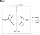
- FIG. 6 illustrates a relationship between a ratio R2/R1 and a displacement amount of the cylinder according to a comparative example.
- the ratio R2/R1 is 1.0286
- the ratio R2/R1 is 0.9755.
- the displacement amount of the blade hole 104 in FIGS. 5 and 6 indicates the displacement amount in the radial direction of the blade hole 104 before and after press-fitting.
- mark x indicates an original shape of the blade hole 104 before the pipe connection member 200 is press-fitted into the second suction port 120 (suction passage)
- mark ⁇ indicates a deformed shape thereof after the pipe connection member 200 is press-fitted into the second suction port 120 (suction passage). It should be noted that the deformed shape marked with ⁇ is obtained by adding, to the original shape, the displacement amount multiplied by a factor of 500.
- the compressor 21 having the above-described configuration, by setting the distance R2 from the center point O1 of the cylinder chamber 103 to the press-fitting portion 200b of the pipe connection member 200 to be equal to or longer than the distance R1 to the radially outer end of the blade hole 104, deformation of the blade hole 104 in the cylinder 101 can be suppressed when the press-fitting portion 201b of the pipe connection member 200 is press-fitted into the second suction port 120 (suction passage) of the cylinder 101, thereby suppressing the occurrence of abnormal wear and seizure of the blade 102b.
- the second suction port 120 (suction passage) communicates with the compression chamber 103b (high pressure side region) of the cylinder chamber 103, and the refrigerant from the pipe connection member 200 is supplied to the compression chamber 103b of the cylinder chamber 103 via the second suction port 120, so that the intermediate-pressure refrigerant is introduced into the compression chamber 103b of the cylinder chamber 103 via the second suction port 120, whereby refrigerating capacity can be improved.
- valve structure 210 installed in the second suction port 120 regulates the flow of the refrigerant from the high pressure side region of the cylinder chamber 103 toward the pipe connection member 200 between the pipe connection member 200 and the cylinder chamber 103, the refrigerant can be prevented from flowing back from the compressor 21 side via the second suction port 120.
- the ratio R2/R1 is 1.0286, but the ratio R2/R1 of the distance R2 from the center point O1 of the cylinder chamber 103 to the press-fitting portion 201b of the pipe connection member 200 to the distance R1 from the center point O1 of the cylinder chamber 103 to the radially outer end of the blade hole 104 is preferably 1.02 or more.
- the press-fitting portion 201b of the pipe connection member 200 is press-fitted into the second suction port 120 (suction passage) of the cylinder 101, deformation of the blade hole 104 in the cylinder 101 can be suppressed.
- the straight line x passing through the center point O2 between the two ends connected to the blade hole 104 in the inner peripheral surface of the cylinder chamber 103 and the center point O1 of the cylinder chamber 103 preferably intersects the center axis y of the second suction port 120 (suction passage) at an acute angle.
- a compressor according to a second embodiment of the present disclosure has the same configuration as the compressor 21 according to the first embodiment except for a valve structure.
- the compressor according to the second embodiment has a valve structure that regulates the flow of the refrigerant from the high pressure side region of the cylinder chamber to the outside via the pipe connection member being installed outside the compressor.
- the compressor according to the second embodiment has effects similar to those of the compressor 21 according to the first embodiment.
- the compressor having one cylinder has been described, but the present disclosure may be applied to a compressor having two cylinders or to a compressor having another configuration.
- the air conditioner as the refrigeration apparatus has been described, but the refrigeration apparatus is not limited to the air conditioner and may be a refrigeration apparatus having another configuration.
Landscapes
- Engineering & Computer Science (AREA)
- Mechanical Engineering (AREA)
- General Engineering & Computer Science (AREA)
- Applications Or Details Of Rotary Compressors (AREA)
- Devices That Are Associated With Refrigeration Equipment (AREA)
Abstract
Description
- The present disclosure relates to compressors and a refrigeration apparatuses.
- Conventionally, a compressor has a cylinder provided with a suction passage. A suction pipe is attached to the suction passage via a connection member (see, for example,
JP H6-213183 A - In the compressor, an end portion of the connection member is press-fitted and fixed to the suction passage of the cylinder.
- In the compressor, the end portion (the press-fitting portion) of the connection member is expanded. Therefore, there is a problem of deformation of a blade hole in the cylinder. This causes abnormal wear or seizure of the blade to occur in the compressor.
- The present disclosure proposes a compressor capable of suppressing deformation of a blade hole, and a refrigeration apparatus including the compressor.
- A compressor of the present disclosure includes:
- a cylinder;
- a cylinder chamber defined by an inner peripheral surface of the cylinder;
- a piston housed in the cylinder chamber and turning along the inner peripheral surface of the cylinder;
- a blade that partitions the cylinder chamber into a high pressure side region and a low pressure side region together with the piston;
- a blade hole provided in the cylinder, communicating with the cylinder chamber, and allowing the blade to advance and retreat;
- a suction passage that extends from an outer peripheral surface of the cylinder to the inner peripheral surface of the cylinder and guides a refrigerant to the cylinder chamber; and
- a pipe connection member having a press-fitting portion press-fitted into the suction passage from a radially outer side of the cylinder,
- in which a distance from a center point of the cylinder chamber to the press-fitting portion is equal to or longer than a distance to a radially outer end of the blade hole.
- According to the present disclosure, the distance from the center point of the cylinder chamber to the press-fitting portion is set to be equal to or longer than the distance to the radially outer end of the blade hole, whereby deformation of the blade hole in the cylinder can be suppressed when the press-fitting portion of the pipe connection member is press-fitted into the suction passage of the cylinder.
- Further, in the compressor according to one aspect of the present disclosure, the suction passage communicates with the high pressure side region of the cylinder chamber, and a refrigerant from the pipe connection member is supplied to the high pressure side region of the cylinder chamber via the suction passage.
- According to the present disclosure, for example, an intermediate-pressure refrigerant is introduced into the high pressure side region of the cylinder chamber via the suction passage, whereby refrigerating capacity can be improved.
- Further, the compressor according to one aspect of the present disclosure includes a valve structure that is installed in the suction passage and regulates a flow of a refrigerant from the high pressure side region of the cylinder chamber toward the pipe connection member.
- According to the present disclosure, the valve structure installed in the suction passage restricts the flow of the refrigerant from the high pressure side region of the cylinder chamber toward the pipe connection member between the pipe connection member and the cylinder chamber. This can prevent the refrigerant from flowing back from the compressor side via the suction passage.
- Further, in the compressor according to one aspect of the present disclosure, a ratio R2/R1 of the distance from the center point of the cylinder chamber to the press-fitting portion to the distance from the center point of the cylinder chamber to the radially outer end of the blade hole is 1.02 or more.
- According to the present disclosure, when the press-fitting portion of the pipe connection member is press-fitted into the suction passage of the cylinder, deformation of the blade hole in the cylinder can be suppressed.
- Further, in the compressor according to one aspect of the present disclosure,
- the inner peripheral surface has two ends continuous with the blade hole, and
- in plan view, a straight line passing through a midpoint between the two ends of the inner peripheral surface and the center point of the cylinder chamber intersects a center axis of the suction passage at an acute angle.
- According to the present disclosure, even in a compressor having a large amount of deformation when the press-fitting portion of the pipe connection member is press-fitted into the suction passage of the cylinder, deformation of the blade hole in the cylinder can be suppressed.
- A refrigeration apparatus according to the present disclosure includes any one of the above compressors.
- According to the present disclosure, the compressor capable of suppressing deformation of the blade hole in the cylinder to thereby suppress the occurrence of abnormal wear and seizure of the blade is used, whereby a highly reliable refrigeration apparatus can be realized.
-
-
FIG. 1 is a configuration diagram of a refrigerant circuit of an air conditioner using a compressor according to a first embodiment of the present disclosure; -
FIG. 2 is a top plan view of a main part including a cylinder and a piston of the compressor according to the first embodiment; -
FIG. 3 is a cross-sectional view of the cylinder according to the first embodiment; -
FIG. 4 is a graph illustrating a relationship between a ratio R2/R1 and a displacement amount according to the first embodiment; -
FIG. 5 is a diagram illustrating the relationship between the ratio R2/R1 and the displacement amount according to the first embodiment; and -
FIG. 6 is a diagram illustrating a relationship between a ratio R2/R1 and a displacement amount according to a comparative example. - Hereinafter, embodiments will be described. It should be noted that in the drawings, the same reference numerals represent the same or corresponding parts. In addition, the dimensions on the drawings such as a length, a width, a thickness, and a depth are appropriately changed from the actual scale for the purpose of clarifying and simplifying the drawings, and do not represent the actual relative dimensions.
-
FIG. 1 is a configuration diagram of a refrigerant circuit of an air conditioner including acompressor 21 according to a first embodiment of the present disclosure. This air conditioner is an example of a refrigeration apparatus. InFIG. 1 ,reference numeral 13 denotes an indoor fan that causes indoor air to flow to anindoor heat exchanger 12, andreference numeral 28 denotes an outdoor fan that causes outside air to flow to anoutdoor heat exchanger 23. - As illustrated in
FIG. 1 , the air conditioner includes anindoor unit 1 and anoutdoor unit 2 connected via a part of a refrigerant circuit RC. Theindoor unit 1 includes theindoor heat exchanger 12, theindoor fan 13, and the like. On the other hand, theoutdoor unit 2 includes theoutdoor heat exchanger 23, theoutdoor fan 28, and the like. The refrigerant circuit RC is filled with a refrigerant that circulates to achieve a refrigeration cycle. Thecompressor 21, a four-way switching valve 22, theoutdoor heat exchanger 23, anoutdoor expansion valve 24, a gas-liquid separator 25, anindoor expansion valve 11, and theindoor heat exchanger 12 are annularly connected to the refrigerant circuit RC. In other words, the refrigerant circuit RC are configure so that refrigerant discharged from thecompressor 21 return to thecompressor 21 through the four-way switching valve 22, theoutdoor heat exchanger 23, theoutdoor expansion valve 24, the gas-liquid separator 25, theindoor expansion valve 11, and theindoor heat exchanger 12. A first port P1 of the four-way switching valve 22 is connected to a discharge side of thecompressor 21 via a discharge pipe L1. A second port P2 of the four-way switching valve 22 is connected to a first suction port 110 (illustrated inFIGS. 2 and3 ) of thecompressor 21 via a suction pipe L4. A third port P3 of the four-way switching valve 22 is connected to one end of theoutdoor heat exchanger 23. A fourth port P4 of the four-way switching valve 22 is connected to one end of theindoor heat exchanger 12. - The inside of the gas-
liquid separator 25 is connected to one end of an intermediate injection pipe L2, and the other end of the intermediate injection pipe L2 is connected to one end of an intermediateelectromagnetic valve 26. The other end of the intermediateelectromagnetic valve 26 is connected to one end of an intermediate pipe L3, and the other end of the intermediate pipe L3 is connected to a second suction port 120 (illustrated inFIGS. 2 and3 ) of thecompressor 21. - The intermediate pipe L3 is connected to one end of a suction communication pipe L5, and the other end of the suction communication pipe L5 is connected to the suction pipe L4 of the
compressor 21. The suction communication pipe L5A is provided with a suctionelectromagnetic valve 27 that is an on-off valve. - In cooling operation, the four-
way switching valve 22 is in a first state (a state indicated by a broken line inFIG. 1 ), and the first port P1 and the third port P3 communicate with each other, and at the same time, the second port P2 and the fourth port P4 communicate with each other. The refrigerant compressed by thecompressor 21 is condensed by theoutdoor heat exchanger 23, decompressed by theindoor expansion valve 11, and evaporated by theindoor heat exchanger 12. - In heating operation, the four-
way switching valve 22 is in a second state (a state indicated by a solid line inFIG. 1 ), the first port P1 and the fourth port P4 communicate with each other, and at the same time, the second port P2 and the third port P3 communicate with each other. The refrigerant compressed by thecompressor 21 is condensed by theindoor heat exchanger 12, decompressed by theoutdoor expansion valve 24, and evaporated by theoutdoor heat exchanger 23. - In the refrigerant circuit RC, an injection operation for introducing an intermediate-pressure refrigerant into a high pressure side region in the
compressor 21 is performed. When the injection operation is performed, the intermediateelectromagnetic valve 26 is opened and the suctionelectromagnetic valve 27 is closed. As a result, the intermediate-pressure refrigerant in the gas-liquid separator 25 is introduced into the intermediate pipe L3 of thecompressor 21 through the intermediate injection pipe L2. When the injection operation is stopped, the intermediateelectromagnetic valve 26 is closed and the suctionelectromagnetic valve 27 is opened. -
FIG. 2 is a top plan view of acylinder 101 and aswing member 102 of thecompressor 21. InFIG. 2 , acylinder chamber 103 defined by an innerperipheral surface 101a is formed in thecylinder 101. - As illustrated in
FIG. 2 , thecompressor 21 includes theswing member 102 swinging in thecylinder 101. Theswing member 102 has apiston 102a housed in thecylinder chamber 103 and ablade 102b integrally formed with thepiston 102a. The inside of thecylinder chamber 103 is partitioned by thepiston 102a and theblade 102b. Asuction chamber 103a (low pressure side region) is formed on the right side of thepiston 102a and theblade 102b, and acompression chamber 103b (high pressure side region) is formed on the left side of thepiston 102a and theblade 102b. Thepiston 102a and theblade 102b partition thecylinder chamber 103 into the high pressure side region and the low pressure side region, respectively. - The
first suction port 110 penetrating in the radial direction is formed on the right side (suction chamber 103a side) of theblade 102b in thecylinder 101. Thefirst suction port 110 opens to thesuction chamber 103a on the right side of theblade 102b. The suction pipe L4 (illustrated inFIG. 1 ) is connected to thefirst suction port 110 from the outside. - The
second suction port 120 penetrating in the radial direction is formed on the left side (compression chamber 103b side) of theblade 102b in thecylinder 101. Thesecond suction port 120 opens to thecompression chamber 103b on the left side of theblade 102b. Apipe connection member 200 is connected to thesecond suction port 120 from the outside. Thesecond suction port 120 is an example of a suction passage. A press-fittingportion 201b (illustrated inFIG. 3 ) of thepipe connection member 200 is press-fitted into the second suction port 120 (suction passage) from a radially outer side of thecylinder 101. The intermediate pipe L3 (illustrated inFIG. 1 ) is connected to thepipe connection member 200 from the outside. The intermediate pipe L3 (illustrated inFIG. 1 ) is connected to thepipe connection member 200 by welding from the outside. - A
blade hole 104 of thecylinder 101 is a bush hole provided in thecylinder 101 in continuation with thecylinder chamber 103. A pair of swinging bushings 105,105 are disposed in theblade hole 104. - Lubricating oil lubricates between the
blade 102b and the swinging bushings 105,105. These swingingbushings blade 102b from both sides, thereby support theblade 102b so as to be able to advance and retract. Theblade 102b protrudes into and retracts from aback surface space 106 provided in thecylinder 101. - A
shaft 140 has aneccentric portion 150 disposed in thecylinder chamber 103. Theeccentric portion 150 is provided so as to be eccentric with respect to a center axis of theshaft 140. As theshaft 140 rotates clockwise, theeccentric portion 150 eccentrically rotates, and thepiston 102a fitted to theeccentric portion 150 turns along the innerperipheral surface 101a of thecylinder chamber 103. As thepiston 102a revolves in thecylinder chamber 103, low-pressure refrigerant gas is sucked into thesuction chamber 103a from thefirst suction port 110 and compressed into a high pressure in thecompression chamber 103b, and thereafter, the high-pressure refrigerant gas is discharged from a discharge port 130 (illustrated inFIG. 3 ). During the injection operation, the intermediate-pressure refrigerant is introduced from thesecond suction port 120 into thecompression chamber 103b. Thereafter, the refrigerant gas discharged from thedischarge port 130 is exhausted from the discharge pipe L1 of thecompressor 21. -
FIG. 3 is a cross-sectional view of thecylinder 101 taken along a plane orthogonal to the shaft 140 (illustrated inFIG. 2 ). InFIG. 3 ,reference numeral 130 denotes a discharge port formed on the left side (compression chamber 103b side) of theblade 102b in thecylinder 101. - An intermediate pipe L3 (illustrated in
FIG. 1 ) is connected to an inflow end of the second suction port 120 (radially outer side of the cylinder 101). An outflow end of the second suction port 120 (radially inner side of the cylinder 101) opens to thecompression chamber 103b of thecylinder chamber 103. As a result, the intermediate pipe L3 and thecompression chamber 103b communicate with each other via thesecond suction port 120. The refrigerant is guided to thecylinder chamber 103 through thesecond suction port 120 extending from the outer peripheral surface of thecylinder 101 to the innerperipheral surface 101a of thecylinder 101. - Here, in plan view, a straight line x passes through a center point O1 and O2. The center point O2 lies halfway between two ends of the inner
peripheral surface 101a of thecylinder chamber 103. The two ends are continuous with theblade hole 104. That is, the two ends are border between theblade hole 104 and the innerperipheral surface 101a of thecylinder chamber 103. The straight line x intersects a center axis y of the second suction port 120 (suction passage) at an angle θ (for example, 25 deg). - The
pipe connection member 200 press-fitted into the second suction port 120 (suction passage) from the radially outer side of thecylinder 101 has acylindrical body 201, anannular valve body 202, and anannular valve seat 203. - The
cylindrical body 201 includes aflange portion 201a, the press-fittingportion 201b, and avalve pressing portion 201c in this order from the radially outer side of thecylinder 101. Thevalve pressing portion 201c has a plurality of throughholes 201d penetrating in the axial direction. The plurality of throughholes 201d are annularly arranged around the center axis y of thesecond suction port 120. - When a refrigerant pressure in the
compression chamber 103b of thecylinder chamber 103 is lower than a refrigerant pressure in the intermediate pipe L3 connected to thepipe connection member 200, theannular valve body 202 is pressed against thevalve seat 203. As a result, the refrigerant from the intermediate pipe L3 flows from the plurality of throughholes 201d of thevalve pressing portion 201c into thecompression chamber 103b of thecylinder chamber 103 through thecenter hole 202a of thevalve body 202 and thecenter hole 203a of thevalve seat 203. - On the other hand, when the refrigerant pressure in the
compression chamber 103b of thecylinder chamber 103 is higher than the refrigerant pressure in the intermediate pipe L3 connected to thepipe connection member 200, theannular valve body 202 is pressed against thevalve pressing portion 201c. As a result, the plurality of throughholes 201d of thevalve pressing portion 201c are closed by thevalve body 202, thereby regulating the flow of the refrigerant from thecompression chamber 103b (high pressure side region) of thecylinder chamber 103 toward the outside via thepipe connection member 200. - The
valve pressing portion 201c of thecylindrical body 201, thevalve body 202, and thevalve seat 203 constitute avalve structure 210 for opening and closing thesecond suction port 120. Thevalve structure 210 is located between a radially outer end of thepipe connection member 200 and thecylinder chamber 103. In the present embodiment, thevalve structure 210 including thevalve pressing portion 201c of thebody 201, thevalve body 202, and thevalve seat 203 is used, but the valve structure is not limited thereto, and a valve structure having another configuration may be used. - As illustrated in
FIG. 3 , a distance R2 from the center point O1 of thecylinder chamber 103 to the press-fittingportion 201b of thepipe connection member 200 is equal to or longer than a distance R1 from the center point O1 of thecylinder chamber 103 to the radially outer end of theblade hole 104. -
FIG. 4 illustrates a relationship between a ration (R2/R1) of the distance R2 to the distance R1 and displacement of theblade hole 104, the relationship obtained by simulation using finite element method (FEM) analysis. InFIG. 4 , a horizontal axis represents the ration (R2/R1), and a vertical axis represents a ratio of displacement obtained when the displacement of theblade hole 104 with a difference (R2-R1) between the distance R2 and the distance R1 of -1.2 mm is 100. The displacement of theblade hole 104 inFIG. 4 represents (maximum value-minimum value) of the distortion in the radial direction of theblade hole 104. - As illustrated in
FIG. 4 , when the ratio R2/R1 is 1.0286, the displacement amount is about 68 as compared with the case where the ratio is 0.9755. When the ratio R2/R1 is 1.0837, the displacement amount is about 52 as compared with the case where the ratio is 0.9755. -
FIG. 5 illustrates a relationship between the ratio R2/R1 and the displacement amount of thecylinder 101 according to the first embodiment, the relationship obtained by simulation using finite element method (FEM) analysis, andFIG. 6 illustrates a relationship between a ratio R2/R1 and a displacement amount of the cylinder according to a comparative example. InFIG. 5 , the ratio R2/R1 is 1.0286, and inFIG. 6 , the ratio R2/R1 is 0.9755. The displacement amount of theblade hole 104 inFIGS. 5 and6 indicates the displacement amount in the radial direction of theblade hole 104 before and after press-fitting. - In
FIGS. 5 and6 , mark x indicates an original shape of theblade hole 104 before thepipe connection member 200 is press-fitted into the second suction port 120 (suction passage), and mark ◊ indicates a deformed shape thereof after thepipe connection member 200 is press-fitted into the second suction port 120 (suction passage). It should be noted that the deformed shape marked with ◊ is obtained by adding, to the original shape, the displacement amount multiplied by a factor of 500. - According to the
compressor 21 having the above-described configuration, by setting the distance R2 from the center point O1 of thecylinder chamber 103 to the press-fitting portion 200b of thepipe connection member 200 to be equal to or longer than the distance R1 to the radially outer end of theblade hole 104, deformation of theblade hole 104 in thecylinder 101 can be suppressed when the press-fittingportion 201b of thepipe connection member 200 is press-fitted into the second suction port 120 (suction passage) of thecylinder 101, thereby suppressing the occurrence of abnormal wear and seizure of theblade 102b. - Further, the second suction port 120 (suction passage) communicates with the
compression chamber 103b (high pressure side region) of thecylinder chamber 103, and the refrigerant from thepipe connection member 200 is supplied to thecompression chamber 103b of thecylinder chamber 103 via thesecond suction port 120, so that the intermediate-pressure refrigerant is introduced into thecompression chamber 103b of thecylinder chamber 103 via thesecond suction port 120, whereby refrigerating capacity can be improved. - In addition, since the
valve structure 210 installed in the second suction port 120 (suction passage) regulates the flow of the refrigerant from the high pressure side region of thecylinder chamber 103 toward thepipe connection member 200 between thepipe connection member 200 and thecylinder chamber 103, the refrigerant can be prevented from flowing back from thecompressor 21 side via thesecond suction port 120. - In the first embodiment, the ratio R2/R1 is 1.0286, but the ratio R2/R1 of the distance R2 from the center point O1 of the
cylinder chamber 103 to the press-fittingportion 201b of thepipe connection member 200 to the distance R1 from the center point O1 of thecylinder chamber 103 to the radially outer end of theblade hole 104 is preferably 1.02 or more. As a result, when the press-fittingportion 201b of thepipe connection member 200 is press-fitted into the second suction port 120 (suction passage) of thecylinder 101, deformation of theblade hole 104 in thecylinder 101 can be suppressed. - In plan view, the straight line x passing through the center point O2 between the two ends connected to the
blade hole 104 in the inner peripheral surface of thecylinder chamber 103 and the center point O1 of thecylinder chamber 103 preferably intersects the center axis y of the second suction port 120 (suction passage) at an acute angle. As a result, even in a compressor having a large amount of deformation when the press-fittingportion 201b of thepipe connection member 200 is press-fitted into thesecond suction port 120 of thecylinder 101, deformation of theblade hole 104 in thecylinder 101 can be suppressed. - In addition, by using the
compressor 21 capable of suppressing deformation of theblade hole 104 in thecylinder 101 to thereby suppress the occurrence of abnormal wear and seizure of the blade 101b, a highly reliable air conditioner can be realized. - A compressor according to a second embodiment of the present disclosure has the same configuration as the
compressor 21 according to the first embodiment except for a valve structure. The compressor according to the second embodiment has a valve structure that regulates the flow of the refrigerant from the high pressure side region of the cylinder chamber to the outside via the pipe connection member being installed outside the compressor. - The compressor according to the second embodiment has effects similar to those of the
compressor 21 according to the first embodiment. - In the first and second embodiments, the compressor having one cylinder has been described, but the present disclosure may be applied to a compressor having two cylinders or to a compressor having another configuration.
- In the first and second embodiments, the air conditioner as the refrigeration apparatus has been described, but the refrigeration apparatus is not limited to the air conditioner and may be a refrigeration apparatus having another configuration.
- Although specific embodiments of the present disclosure have been described, the present disclosure is not limited to the first and second embodiments, and various modifications can be made within the scope of the present disclosure and implemented. For example, although the
swing member 102 in which thepiston 102a and theblade 102b are integrally formed is used, a swing member in which a piston and a blade are separately formed may be used.
Claims (6)
- A compressor (21) comprising:a cylinder (101);a cylinder chamber (103) defined by an inner peripheral surface (101a) of the cylinder (101);a piston (102a) housed in the cylinder chamber (103) and turning along the inner peripheral surface (101a) of the cylinder (101);a blade (102b) that partitions the cylinder chamber (103) into a high pressure side region (103b) and a low pressure side region (103a) together with the piston (102a);a blade hole (104) provided in the cylinder(101), communicating with the cylinder chamber (103), and allowing the blade (102b) to advance and retreat;a suction passage (120) that extends from an outer peripheral surface of the cylinder (101) to the inner peripheral surface (101a) of the cylinder (101) and guides a refrigerant to the cylinder chamber (103); anda pipe connection member (200) having a press-fitting portion (201b) press-fitted into the suction passage (120) from a radially outer side of the cylinder (101),wherein a distance (R2) from a center point (O1) of the cylinder chamber (103) to the press-fitting portion (201b) is equal to or longer than a distance (R1) to a radially outer end of the blade hole (104).
- The compressor (21) according to claim 1, wherein
the suction passage (120) communicates with the high pressure side region (103b) of the cylinder chamber (103), and a refrigerant from the pipe connection member (200) is supplied to the high pressure side region (103b) of the cylinder chamber (103) via the suction passage (120). - The compressor (21) according to claim 2, further comprising a valve structure (210) that is installed in the suction passage (120) and regulates a flow of a refrigerant from the high pressure side region (103b) of the cylinder chamber (103) toward the pipe connection member (200).
- The compressor (21) according to any one of claims 1 to 3, wherein
a ratio (R2/R1) of the distance (R2) from the center point (O1) of the cylinder chamber (103) to the press-fitting portion (201b) to the distance (R1) from the center point (O1) of the cylinder chamber (103) to the radially outer end of the blade hole (104) is 1.02 or more. - The compressor (21) according to claim 2 or 3, whereinthe inner peripheral surface (101a) has two ends continuous with the blade hole (104), andin plan view, a straight line (x) passing through a midpoint (O2) between the two ends of the inner peripheral surface (101a) and the center point (O1) of the cylinder chamber (103) intersects a center axis (y) of the suction passage (120) at an acute angle.
- A refrigeration apparatus comprising a compressor (21) according to any one of claims 1 to 5.
Applications Claiming Priority (1)
| Application Number | Priority Date | Filing Date | Title |
|---|---|---|---|
| JP2020195464A JP7393666B2 (en) | 2020-11-25 | 2020-11-25 | Compressor and refrigeration equipment |
Publications (3)
| Publication Number | Publication Date |
|---|---|
| EP4006346A2 true EP4006346A2 (en) | 2022-06-01 |
| EP4006346A3 EP4006346A3 (en) | 2022-06-08 |
| EP4006346B1 EP4006346B1 (en) | 2023-06-07 |
Family
ID=78725257
Family Applications (1)
| Application Number | Title | Priority Date | Filing Date |
|---|---|---|---|
| EP21209445.2A Active EP4006346B1 (en) | 2020-11-25 | 2021-11-22 | Rotary compressor and refrigeration apparatus |
Country Status (3)
| Country | Link |
|---|---|
| EP (1) | EP4006346B1 (en) |
| JP (1) | JP7393666B2 (en) |
| ES (1) | ES2953284T3 (en) |
Citations (1)
| Publication number | Priority date | Publication date | Assignee | Title |
|---|---|---|---|---|
| JPH06213183A (en) | 1993-01-21 | 1994-08-02 | Matsushita Refrig Co Ltd | Intake device for rotary compressor |
Family Cites Families (6)
| Publication number | Priority date | Publication date | Assignee | Title |
|---|---|---|---|---|
| JPS6027836Y2 (en) * | 1976-12-23 | 1985-08-22 | 株式会社東芝 | compressor |
| JPS58109591U (en) * | 1982-01-20 | 1983-07-26 | 三菱電機株式会社 | rotary compressor |
| JPH0988856A (en) * | 1995-09-20 | 1997-03-31 | Daikin Ind Ltd | Rotary compressor |
| JP2003262192A (en) * | 2002-03-07 | 2003-09-19 | Daikin Ind Ltd | Hermetic compressor |
| JP2006152931A (en) | 2004-11-30 | 2006-06-15 | Hitachi Home & Life Solutions Inc | Rotary type two-stage compressor |
| JP5685939B2 (en) * | 2010-12-29 | 2015-03-18 | ダイキン工業株式会社 | Compressor |
-
2020
- 2020-11-25 JP JP2020195464A patent/JP7393666B2/en active Active
-
2021
- 2021-11-22 EP EP21209445.2A patent/EP4006346B1/en active Active
- 2021-11-22 ES ES21209445T patent/ES2953284T3/en active Active
Patent Citations (1)
| Publication number | Priority date | Publication date | Assignee | Title |
|---|---|---|---|---|
| JPH06213183A (en) | 1993-01-21 | 1994-08-02 | Matsushita Refrig Co Ltd | Intake device for rotary compressor |
Also Published As
| Publication number | Publication date |
|---|---|
| EP4006346A3 (en) | 2022-06-08 |
| ES2953284T3 (en) | 2023-11-10 |
| EP4006346B1 (en) | 2023-06-07 |
| JP2022083876A (en) | 2022-06-06 |
| JP7393666B2 (en) | 2023-12-07 |
Similar Documents
| Publication | Publication Date | Title |
|---|---|---|
| US12421967B2 (en) | Rotary compressor and refrigeration device | |
| EP1674731B1 (en) | Rotary fluid machine | |
| JP6568841B2 (en) | Hermetic rotary compressor and refrigeration air conditioner | |
| US11231035B2 (en) | Scroll compressor | |
| US11906060B2 (en) | Rotary compressor with backflow suppresion mechanism for an introduction path | |
| EP4006346B1 (en) | Rotary compressor and refrigeration apparatus | |
| JP2005307764A (en) | Rotary compressor | |
| CN118202151A (en) | Compressor and refrigeration cycle device | |
| KR100620044B1 (en) | Variable capacity device of rotary compressor | |
| US10968911B2 (en) | Oscillating piston-type compressor | |
| US7556485B2 (en) | Rotary compressor with reduced refrigeration gas leaks during compression while preventing seizure | |
| KR100724452B1 (en) | Variable displacement rotary compressors | |
| JP4024056B2 (en) | Rotary compressor | |
| JP3616056B2 (en) | Rotary compressor | |
| JP7745664B2 (en) | Compressor and refrigeration cycle device equipped with said compressor | |
| EP2857688B1 (en) | Rotary compressor | |
| JP2015028313A (en) | Axial vane type compressor | |
| JP3913507B2 (en) | Rotary compressor | |
| JP5217869B2 (en) | Two-stage compressor | |
| JP2019214949A (en) | Vane rotary type gas compressor | |
| WO2026070228A1 (en) | Rotary compressor and refrigeration device | |
| JP2025133199A (en) | Rotary compressor, refrigeration device, and method for manufacturing rotary compressor | |
| CN114270044A (en) | Scroll compressor having a plurality of scroll members | |
| WO2022269752A1 (en) | Rotary compressor and refrigeration cycle device | |
| JP2006233975A (en) | Rotary compressor |
Legal Events
| Date | Code | Title | Description |
|---|---|---|---|
| PUAI | Public reference made under article 153(3) epc to a published international application that has entered the european phase |
Free format text: ORIGINAL CODE: 0009012 |
|
| STAA | Information on the status of an ep patent application or granted ep patent |
Free format text: STATUS: REQUEST FOR EXAMINATION WAS MADE |
|
| PUAL | Search report despatched |
Free format text: ORIGINAL CODE: 0009013 |
|
| 17P | Request for examination filed |
Effective date: 20211213 |
|
| AK | Designated contracting states |
Kind code of ref document: A2 Designated state(s): AL AT BE BG CH CY CZ DE DK EE ES FI FR GB GR HR HU IE IS IT LI LT LU LV MC MK MT NL NO PL PT RO RS SE SI SK SM TR |
|
| AK | Designated contracting states |
Kind code of ref document: A3 Designated state(s): AL AT BE BG CH CY CZ DE DK EE ES FI FR GB GR HR HU IE IS IT LI LT LU LV MC MK MT NL NO PL PT RO RS SE SI SK SM TR |
|
| RIC1 | Information provided on ipc code assigned before grant |
Ipc: F04C 29/12 20060101ALI20220503BHEP Ipc: F04C 18/32 20060101AFI20220503BHEP |
|
| RBV | Designated contracting states (corrected) |
Designated state(s): AL AT BE BG CH CY CZ DE DK EE ES FI FR GB GR HR HU IE IS IT LI LT LU LV MC MK MT NL NO PL PT RO RS SE SI SK SM TR |
|
| RAP3 | Party data changed (applicant data changed or rights of an application transferred) |
Owner name: DAIKIN INDUSTRIES, LTD. |
|
| GRAP | Despatch of communication of intention to grant a patent |
Free format text: ORIGINAL CODE: EPIDOSNIGR1 |
|
| STAA | Information on the status of an ep patent application or granted ep patent |
Free format text: STATUS: GRANT OF PATENT IS INTENDED |
|
| INTG | Intention to grant announced |
Effective date: 20230216 |
|
| GRAS | Grant fee paid |
Free format text: ORIGINAL CODE: EPIDOSNIGR3 |
|
| GRAA | (expected) grant |
Free format text: ORIGINAL CODE: 0009210 |
|
| STAA | Information on the status of an ep patent application or granted ep patent |
Free format text: STATUS: THE PATENT HAS BEEN GRANTED |
|
| AK | Designated contracting states |
Kind code of ref document: B1 Designated state(s): AL AT BE BG CH CY CZ DE DK EE ES FI FR GB GR HR HU IE IS IT LI LT LU LV MC MK MT NL NO PL PT RO RS SE SI SK SM TR |
|
| REG | Reference to a national code |
Ref country code: GB Ref legal event code: FG4D |
|
| REG | Reference to a national code |
Ref country code: CH Ref legal event code: EP Ref country code: AT Ref legal event code: REF Ref document number: 1575844 Country of ref document: AT Kind code of ref document: T Effective date: 20230615 |
|
| REG | Reference to a national code |
Ref country code: DE Ref legal event code: R096 Ref document number: 602021002793 Country of ref document: DE |
|
| P01 | Opt-out of the competence of the unified patent court (upc) registered |
Effective date: 20230525 |
|
| REG | Reference to a national code |
Ref country code: LT Ref legal event code: MG9D |
|
| REG | Reference to a national code |
Ref country code: NL Ref legal event code: MP Effective date: 20230607 |
|
| PG25 | Lapsed in a contracting state [announced via postgrant information from national office to epo] |
Ref country code: SE Free format text: LAPSE BECAUSE OF FAILURE TO SUBMIT A TRANSLATION OF THE DESCRIPTION OR TO PAY THE FEE WITHIN THE PRESCRIBED TIME-LIMIT Effective date: 20230607 Ref country code: NO Free format text: LAPSE BECAUSE OF FAILURE TO SUBMIT A TRANSLATION OF THE DESCRIPTION OR TO PAY THE FEE WITHIN THE PRESCRIBED TIME-LIMIT Effective date: 20230907 |
|
| REG | Reference to a national code |
Ref country code: ES Ref legal event code: FG2A Ref document number: 2953284 Country of ref document: ES Kind code of ref document: T3 Effective date: 20231110 |
|
| REG | Reference to a national code |
Ref country code: AT Ref legal event code: MK05 Ref document number: 1575844 Country of ref document: AT Kind code of ref document: T Effective date: 20230607 |
|
| PG25 | Lapsed in a contracting state [announced via postgrant information from national office to epo] |
Ref country code: RS Free format text: LAPSE BECAUSE OF FAILURE TO SUBMIT A TRANSLATION OF THE DESCRIPTION OR TO PAY THE FEE WITHIN THE PRESCRIBED TIME-LIMIT Effective date: 20230607 Ref country code: NL Free format text: LAPSE BECAUSE OF FAILURE TO SUBMIT A TRANSLATION OF THE DESCRIPTION OR TO PAY THE FEE WITHIN THE PRESCRIBED TIME-LIMIT Effective date: 20230607 Ref country code: LV Free format text: LAPSE BECAUSE OF FAILURE TO SUBMIT A TRANSLATION OF THE DESCRIPTION OR TO PAY THE FEE WITHIN THE PRESCRIBED TIME-LIMIT Effective date: 20230607 Ref country code: LT Free format text: LAPSE BECAUSE OF FAILURE TO SUBMIT A TRANSLATION OF THE DESCRIPTION OR TO PAY THE FEE WITHIN THE PRESCRIBED TIME-LIMIT Effective date: 20230607 Ref country code: HR Free format text: LAPSE BECAUSE OF FAILURE TO SUBMIT A TRANSLATION OF THE DESCRIPTION OR TO PAY THE FEE WITHIN THE PRESCRIBED TIME-LIMIT Effective date: 20230607 Ref country code: GR Free format text: LAPSE BECAUSE OF FAILURE TO SUBMIT A TRANSLATION OF THE DESCRIPTION OR TO PAY THE FEE WITHIN THE PRESCRIBED TIME-LIMIT Effective date: 20230908 |
|
| PG25 | Lapsed in a contracting state [announced via postgrant information from national office to epo] |
Ref country code: FI Free format text: LAPSE BECAUSE OF FAILURE TO SUBMIT A TRANSLATION OF THE DESCRIPTION OR TO PAY THE FEE WITHIN THE PRESCRIBED TIME-LIMIT Effective date: 20230607 |
|
| PG25 | Lapsed in a contracting state [announced via postgrant information from national office to epo] |
Ref country code: SK Free format text: LAPSE BECAUSE OF FAILURE TO SUBMIT A TRANSLATION OF THE DESCRIPTION OR TO PAY THE FEE WITHIN THE PRESCRIBED TIME-LIMIT Effective date: 20230607 |
|
| PG25 | Lapsed in a contracting state [announced via postgrant information from national office to epo] |
Ref country code: IS Free format text: LAPSE BECAUSE OF FAILURE TO SUBMIT A TRANSLATION OF THE DESCRIPTION OR TO PAY THE FEE WITHIN THE PRESCRIBED TIME-LIMIT Effective date: 20231007 |
|
| PG25 | Lapsed in a contracting state [announced via postgrant information from national office to epo] |
Ref country code: SM Free format text: LAPSE BECAUSE OF FAILURE TO SUBMIT A TRANSLATION OF THE DESCRIPTION OR TO PAY THE FEE WITHIN THE PRESCRIBED TIME-LIMIT Effective date: 20230607 Ref country code: SK Free format text: LAPSE BECAUSE OF FAILURE TO SUBMIT A TRANSLATION OF THE DESCRIPTION OR TO PAY THE FEE WITHIN THE PRESCRIBED TIME-LIMIT Effective date: 20230607 Ref country code: RO Free format text: LAPSE BECAUSE OF FAILURE TO SUBMIT A TRANSLATION OF THE DESCRIPTION OR TO PAY THE FEE WITHIN THE PRESCRIBED TIME-LIMIT Effective date: 20230607 Ref country code: PT Free format text: LAPSE BECAUSE OF FAILURE TO SUBMIT A TRANSLATION OF THE DESCRIPTION OR TO PAY THE FEE WITHIN THE PRESCRIBED TIME-LIMIT Effective date: 20231009 Ref country code: IS Free format text: LAPSE BECAUSE OF FAILURE TO SUBMIT A TRANSLATION OF THE DESCRIPTION OR TO PAY THE FEE WITHIN THE PRESCRIBED TIME-LIMIT Effective date: 20231007 Ref country code: EE Free format text: LAPSE BECAUSE OF FAILURE TO SUBMIT A TRANSLATION OF THE DESCRIPTION OR TO PAY THE FEE WITHIN THE PRESCRIBED TIME-LIMIT Effective date: 20230607 Ref country code: CZ Free format text: LAPSE BECAUSE OF FAILURE TO SUBMIT A TRANSLATION OF THE DESCRIPTION OR TO PAY THE FEE WITHIN THE PRESCRIBED TIME-LIMIT Effective date: 20230607 Ref country code: AT Free format text: LAPSE BECAUSE OF FAILURE TO SUBMIT A TRANSLATION OF THE DESCRIPTION OR TO PAY THE FEE WITHIN THE PRESCRIBED TIME-LIMIT Effective date: 20230607 |
|
| PG25 | Lapsed in a contracting state [announced via postgrant information from national office to epo] |
Ref country code: PL Free format text: LAPSE BECAUSE OF FAILURE TO SUBMIT A TRANSLATION OF THE DESCRIPTION OR TO PAY THE FEE WITHIN THE PRESCRIBED TIME-LIMIT Effective date: 20230607 |
|
| REG | Reference to a national code |
Ref country code: DE Ref legal event code: R097 Ref document number: 602021002793 Country of ref document: DE |
|
| PLBE | No opposition filed within time limit |
Free format text: ORIGINAL CODE: 0009261 |
|
| STAA | Information on the status of an ep patent application or granted ep patent |
Free format text: STATUS: NO OPPOSITION FILED WITHIN TIME LIMIT |
|
| PG25 | Lapsed in a contracting state [announced via postgrant information from national office to epo] |
Ref country code: DK Free format text: LAPSE BECAUSE OF FAILURE TO SUBMIT A TRANSLATION OF THE DESCRIPTION OR TO PAY THE FEE WITHIN THE PRESCRIBED TIME-LIMIT Effective date: 20230607 |
|
| PG25 | Lapsed in a contracting state [announced via postgrant information from national office to epo] |
Ref country code: SI Free format text: LAPSE BECAUSE OF FAILURE TO SUBMIT A TRANSLATION OF THE DESCRIPTION OR TO PAY THE FEE WITHIN THE PRESCRIBED TIME-LIMIT Effective date: 20230607 |
|
| 26N | No opposition filed |
Effective date: 20240308 |
|
| PG25 | Lapsed in a contracting state [announced via postgrant information from national office to epo] |
Ref country code: SI Free format text: LAPSE BECAUSE OF FAILURE TO SUBMIT A TRANSLATION OF THE DESCRIPTION OR TO PAY THE FEE WITHIN THE PRESCRIBED TIME-LIMIT Effective date: 20230607 |
|
| PG25 | Lapsed in a contracting state [announced via postgrant information from national office to epo] |
Ref country code: MC Free format text: LAPSE BECAUSE OF FAILURE TO SUBMIT A TRANSLATION OF THE DESCRIPTION OR TO PAY THE FEE WITHIN THE PRESCRIBED TIME-LIMIT Effective date: 20230607 |
|
| PG25 | Lapsed in a contracting state [announced via postgrant information from national office to epo] |
Ref country code: LU Free format text: LAPSE BECAUSE OF NON-PAYMENT OF DUE FEES Effective date: 20231122 |
|
| PG25 | Lapsed in a contracting state [announced via postgrant information from national office to epo] |
Ref country code: MC Free format text: LAPSE BECAUSE OF FAILURE TO SUBMIT A TRANSLATION OF THE DESCRIPTION OR TO PAY THE FEE WITHIN THE PRESCRIBED TIME-LIMIT Effective date: 20230607 Ref country code: LU Free format text: LAPSE BECAUSE OF NON-PAYMENT OF DUE FEES Effective date: 20231122 |
|
| REG | Reference to a national code |
Ref country code: BE Ref legal event code: MM Effective date: 20231130 |
|
| REG | Reference to a national code |
Ref country code: IE Ref legal event code: MM4A |
|
| PG25 | Lapsed in a contracting state [announced via postgrant information from national office to epo] |
Ref country code: IE Free format text: LAPSE BECAUSE OF NON-PAYMENT OF DUE FEES Effective date: 20231122 |
|
| PG25 | Lapsed in a contracting state [announced via postgrant information from national office to epo] |
Ref country code: BE Free format text: LAPSE BECAUSE OF NON-PAYMENT OF DUE FEES Effective date: 20231130 |
|
| PG25 | Lapsed in a contracting state [announced via postgrant information from national office to epo] |
Ref country code: IE Free format text: LAPSE BECAUSE OF NON-PAYMENT OF DUE FEES Effective date: 20231122 Ref country code: BE Free format text: LAPSE BECAUSE OF NON-PAYMENT OF DUE FEES Effective date: 20231130 |
|
| PG25 | Lapsed in a contracting state [announced via postgrant information from national office to epo] |
Ref country code: BG Free format text: LAPSE BECAUSE OF FAILURE TO SUBMIT A TRANSLATION OF THE DESCRIPTION OR TO PAY THE FEE WITHIN THE PRESCRIBED TIME-LIMIT Effective date: 20230607 |
|
| PG25 | Lapsed in a contracting state [announced via postgrant information from national office to epo] |
Ref country code: BG Free format text: LAPSE BECAUSE OF FAILURE TO SUBMIT A TRANSLATION OF THE DESCRIPTION OR TO PAY THE FEE WITHIN THE PRESCRIBED TIME-LIMIT Effective date: 20230607 |
|
| REG | Reference to a national code |
Ref country code: CH Ref legal event code: PL |
|
| REG | Reference to a national code |
Ref country code: CH Ref legal event code: PL |
|
| PG25 | Lapsed in a contracting state [announced via postgrant information from national office to epo] |
Ref country code: CH Free format text: LAPSE BECAUSE OF NON-PAYMENT OF DUE FEES Effective date: 20241130 |
|
| PG25 | Lapsed in a contracting state [announced via postgrant information from national office to epo] |
Ref country code: CY Free format text: LAPSE BECAUSE OF FAILURE TO SUBMIT A TRANSLATION OF THE DESCRIPTION OR TO PAY THE FEE WITHIN THE PRESCRIBED TIME-LIMIT; INVALID AB INITIO Effective date: 20211122 |
|
| PG25 | Lapsed in a contracting state [announced via postgrant information from national office to epo] |
Ref country code: TR Free format text: LAPSE BECAUSE OF FAILURE TO SUBMIT A TRANSLATION OF THE DESCRIPTION OR TO PAY THE FEE WITHIN THE PRESCRIBED TIME-LIMIT Effective date: 20230607 |
|
| PGFP | Annual fee paid to national office [announced via postgrant information from national office to epo] |
Ref country code: DE Payment date: 20251119 Year of fee payment: 5 |
|
| PGFP | Annual fee paid to national office [announced via postgrant information from national office to epo] |
Ref country code: GB Payment date: 20251121 Year of fee payment: 5 |
|
| PGFP | Annual fee paid to national office [announced via postgrant information from national office to epo] |
Ref country code: IT Payment date: 20251125 Year of fee payment: 5 |
|
| PGFP | Annual fee paid to national office [announced via postgrant information from national office to epo] |
Ref country code: FR Payment date: 20251126 Year of fee payment: 5 |
|
| PGFP | Annual fee paid to national office [announced via postgrant information from national office to epo] |
Ref country code: ES Payment date: 20251229 Year of fee payment: 5 |
|
| PG25 | Lapsed in a contracting state [announced via postgrant information from national office to epo] |
Ref country code: HU Free format text: LAPSE BECAUSE OF FAILURE TO SUBMIT A TRANSLATION OF THE DESCRIPTION OR TO PAY THE FEE WITHIN THE PRESCRIBED TIME-LIMIT; INVALID AB INITIO Effective date: 20211122 |