EP4005719A1 - Refrigerant piping and refrigeration device - Google Patents
Refrigerant piping and refrigeration device Download PDFInfo
- Publication number
- EP4005719A1 EP4005719A1 EP20848285.1A EP20848285A EP4005719A1 EP 4005719 A1 EP4005719 A1 EP 4005719A1 EP 20848285 A EP20848285 A EP 20848285A EP 4005719 A1 EP4005719 A1 EP 4005719A1
- Authority
- EP
- European Patent Office
- Prior art keywords
- pipe
- diameter portion
- refrigerant
- large diameter
- connection
- Prior art date
- Legal status (The legal status is an assumption and is not a legal conclusion. Google has not performed a legal analysis and makes no representation as to the accuracy of the status listed.)
- Granted
Links
Images





Classifications
-
- B—PERFORMING OPERATIONS; TRANSPORTING
- B23—MACHINE TOOLS; METAL-WORKING NOT OTHERWISE PROVIDED FOR
- B23K—SOLDERING OR UNSOLDERING; WELDING; CLADDING OR PLATING BY SOLDERING OR WELDING; CUTTING BY APPLYING HEAT LOCALLY, e.g. FLAME CUTTING; WORKING BY LASER BEAM
- B23K1/00—Soldering, e.g. brazing, or unsoldering
- B23K1/0008—Soldering, e.g. brazing, or unsoldering specially adapted for particular articles or work
- B23K1/0012—Brazing of heat exchangers
-
- F—MECHANICAL ENGINEERING; LIGHTING; HEATING; WEAPONS; BLASTING
- F25—REFRIGERATION OR COOLING; COMBINED HEATING AND REFRIGERATION SYSTEMS; HEAT PUMP SYSTEMS; MANUFACTURE OR STORAGE OF ICE; LIQUEFACTION SOLIDIFICATION OF GASES
- F25B—REFRIGERATION MACHINES, PLANTS OR SYSTEMS; COMBINED HEATING AND REFRIGERATION SYSTEMS; HEAT PUMP SYSTEMS
- F25B41/00—Fluid-circulation arrangements
- F25B41/40—Fluid line arrangements
- F25B41/42—Arrangements for diverging or converging flows, e.g. branch lines or junctions
-
- B—PERFORMING OPERATIONS; TRANSPORTING
- B23—MACHINE TOOLS; METAL-WORKING NOT OTHERWISE PROVIDED FOR
- B23K—SOLDERING OR UNSOLDERING; WELDING; CLADDING OR PLATING BY SOLDERING OR WELDING; CUTTING BY APPLYING HEAT LOCALLY, e.g. FLAME CUTTING; WORKING BY LASER BEAM
- B23K1/00—Soldering, e.g. brazing, or unsoldering
- B23K1/19—Soldering, e.g. brazing, or unsoldering taking account of the properties of the materials to be soldered
-
- B—PERFORMING OPERATIONS; TRANSPORTING
- B23—MACHINE TOOLS; METAL-WORKING NOT OTHERWISE PROVIDED FOR
- B23K—SOLDERING OR UNSOLDERING; WELDING; CLADDING OR PLATING BY SOLDERING OR WELDING; CUTTING BY APPLYING HEAT LOCALLY, e.g. FLAME CUTTING; WORKING BY LASER BEAM
- B23K1/00—Soldering, e.g. brazing, or unsoldering
- B23K1/20—Preliminary treatment of work or areas to be soldered, e.g. in respect of a galvanic coating
-
- F—MECHANICAL ENGINEERING; LIGHTING; HEATING; WEAPONS; BLASTING
- F16—ENGINEERING ELEMENTS AND UNITS; GENERAL MEASURES FOR PRODUCING AND MAINTAINING EFFECTIVE FUNCTIONING OF MACHINES OR INSTALLATIONS; THERMAL INSULATION IN GENERAL
- F16L—PIPES; JOINTS OR FITTINGS FOR PIPES; SUPPORTS FOR PIPES, CABLES OR PROTECTIVE TUBING; MEANS FOR THERMAL INSULATION IN GENERAL
- F16L13/00—Non-disconnectable pipe joints, e.g. soldered, adhesive, or caulked joints
- F16L13/007—Non-disconnectable pipe joints, e.g. soldered, adhesive, or caulked joints specially adapted for joining pipes of dissimilar materials
-
- F—MECHANICAL ENGINEERING; LIGHTING; HEATING; WEAPONS; BLASTING
- F16—ENGINEERING ELEMENTS AND UNITS; GENERAL MEASURES FOR PRODUCING AND MAINTAINING EFFECTIVE FUNCTIONING OF MACHINES OR INSTALLATIONS; THERMAL INSULATION IN GENERAL
- F16L—PIPES; JOINTS OR FITTINGS FOR PIPES; SUPPORTS FOR PIPES, CABLES OR PROTECTIVE TUBING; MEANS FOR THERMAL INSULATION IN GENERAL
- F16L13/00—Non-disconnectable pipe joints, e.g. soldered, adhesive, or caulked joints
- F16L13/02—Welded joints
- F16L13/0209—Male-female welded joints
-
- F—MECHANICAL ENGINEERING; LIGHTING; HEATING; WEAPONS; BLASTING
- F16—ENGINEERING ELEMENTS AND UNITS; GENERAL MEASURES FOR PRODUCING AND MAINTAINING EFFECTIVE FUNCTIONING OF MACHINES OR INSTALLATIONS; THERMAL INSULATION IN GENERAL
- F16L—PIPES; JOINTS OR FITTINGS FOR PIPES; SUPPORTS FOR PIPES, CABLES OR PROTECTIVE TUBING; MEANS FOR THERMAL INSULATION IN GENERAL
- F16L13/00—Non-disconnectable pipe joints, e.g. soldered, adhesive, or caulked joints
- F16L13/08—Soldered joints
-
- F—MECHANICAL ENGINEERING; LIGHTING; HEATING; WEAPONS; BLASTING
- F25—REFRIGERATION OR COOLING; COMBINED HEATING AND REFRIGERATION SYSTEMS; HEAT PUMP SYSTEMS; MANUFACTURE OR STORAGE OF ICE; LIQUEFACTION SOLIDIFICATION OF GASES
- F25B—REFRIGERATION MACHINES, PLANTS OR SYSTEMS; COMBINED HEATING AND REFRIGERATION SYSTEMS; HEAT PUMP SYSTEMS
- F25B13/00—Compression machines, plants or systems, with reversible cycle
-
- F—MECHANICAL ENGINEERING; LIGHTING; HEATING; WEAPONS; BLASTING
- F25—REFRIGERATION OR COOLING; COMBINED HEATING AND REFRIGERATION SYSTEMS; HEAT PUMP SYSTEMS; MANUFACTURE OR STORAGE OF ICE; LIQUEFACTION SOLIDIFICATION OF GASES
- F25B—REFRIGERATION MACHINES, PLANTS OR SYSTEMS; COMBINED HEATING AND REFRIGERATION SYSTEMS; HEAT PUMP SYSTEMS
- F25B41/00—Fluid-circulation arrangements
- F25B41/20—Disposition of valves, e.g. of on-off valves or flow control valves
- F25B41/26—Disposition of valves, e.g. of on-off valves or flow control valves of fluid flow reversing valves
-
- F—MECHANICAL ENGINEERING; LIGHTING; HEATING; WEAPONS; BLASTING
- F25—REFRIGERATION OR COOLING; COMBINED HEATING AND REFRIGERATION SYSTEMS; HEAT PUMP SYSTEMS; MANUFACTURE OR STORAGE OF ICE; LIQUEFACTION SOLIDIFICATION OF GASES
- F25B—REFRIGERATION MACHINES, PLANTS OR SYSTEMS; COMBINED HEATING AND REFRIGERATION SYSTEMS; HEAT PUMP SYSTEMS
- F25B41/00—Fluid-circulation arrangements
- F25B41/40—Fluid line arrangements
-
- B—PERFORMING OPERATIONS; TRANSPORTING
- B23—MACHINE TOOLS; METAL-WORKING NOT OTHERWISE PROVIDED FOR
- B23K—SOLDERING OR UNSOLDERING; WELDING; CLADDING OR PLATING BY SOLDERING OR WELDING; CUTTING BY APPLYING HEAT LOCALLY, e.g. FLAME CUTTING; WORKING BY LASER BEAM
- B23K2101/00—Articles made by soldering, welding or cutting
- B23K2101/04—Tubular or hollow articles
- B23K2101/06—Tubes
-
- B—PERFORMING OPERATIONS; TRANSPORTING
- B23—MACHINE TOOLS; METAL-WORKING NOT OTHERWISE PROVIDED FOR
- B23K—SOLDERING OR UNSOLDERING; WELDING; CLADDING OR PLATING BY SOLDERING OR WELDING; CUTTING BY APPLYING HEAT LOCALLY, e.g. FLAME CUTTING; WORKING BY LASER BEAM
- B23K2101/00—Articles made by soldering, welding or cutting
- B23K2101/04—Tubular or hollow articles
- B23K2101/14—Heat exchangers
-
- B—PERFORMING OPERATIONS; TRANSPORTING
- B23—MACHINE TOOLS; METAL-WORKING NOT OTHERWISE PROVIDED FOR
- B23K—SOLDERING OR UNSOLDERING; WELDING; CLADDING OR PLATING BY SOLDERING OR WELDING; CUTTING BY APPLYING HEAT LOCALLY, e.g. FLAME CUTTING; WORKING BY LASER BEAM
- B23K2103/00—Materials to be soldered, welded or cut
- B23K2103/02—Iron or ferrous alloys
- B23K2103/04—Steel or steel alloys
- B23K2103/05—Stainless steel
-
- F—MECHANICAL ENGINEERING; LIGHTING; HEATING; WEAPONS; BLASTING
- F25—REFRIGERATION OR COOLING; COMBINED HEATING AND REFRIGERATION SYSTEMS; HEAT PUMP SYSTEMS; MANUFACTURE OR STORAGE OF ICE; LIQUEFACTION SOLIDIFICATION OF GASES
- F25B—REFRIGERATION MACHINES, PLANTS OR SYSTEMS; COMBINED HEATING AND REFRIGERATION SYSTEMS; HEAT PUMP SYSTEMS
- F25B2313/00—Compression machines, plants or systems with reversible cycle not otherwise provided for
- F25B2313/027—Compression machines, plants or systems with reversible cycle not otherwise provided for characterised by the reversing means
- F25B2313/02741—Compression machines, plants or systems with reversible cycle not otherwise provided for characterised by the reversing means using one four-way valve
Definitions
- the present disclosure relates to a refrigerant pipe and a refrigeration apparatus.
- a heat-pump refrigeration apparatus such as an air conditioner includes a refrigerant circuit formed by connecting, with a refrigerant pipe, element components such as a compressor, an oil separator, a four-way switching valve, a heat source-side heat exchanger, an expansion mechanism, a usage-side heat exchanger, an accumulator, and a shutoff valve.
- a copper pipe is used for the refrigerant pipe.
- a material cost of a copper pipe is high, it is considered to use a relatively inexpensive stainless steel refrigerant pipe (see, for example, Patent Literature 1).
- Patent Literature 1 Japanese Unexamined Patent Publication No. 2010-151327
- An object of the present disclosure is to facilitate connection between a refrigerant pipe including stainless steel and a refrigerant pipe including a material other than stainless steel.
- a refrigerant pipe of the present disclosure constitutes a refrigerant circuit of a refrigeration apparatus, the refrigerant pipe including a first pipe and a second pipe, in which the first pipe includes a pipe body including stainless steel and a connection pipe provided at an end of the pipe body in a pipe axial direction and including a material different from stainless steel, the connection pipe has a protrusion protruding in the pipe axial direction from the end of the pipe body, the second pipe includes a second large diameter portion including a material that is same as the material of the connection pipe and disposed at an end in the pipe axial direction, a second small diameter portion having a smaller diameter than the second large diameter portion, and a step portion disposed between the second large diameter portion and the second small diameter portion, the connection pipe is inserted into the second large diameter portion, the protrusion is in contact with the step portion, and the connection pipe has an outer peripheral surface connected to an inner peripheral surface of the second large diameter portion.
- the first pipe of the refrigerant pipe includes the pipe body including stainless steel and the connection pipe provided at the end of the pipe body and including a material different from stainless steel, and the second pipe including a material that is same as the material of the connection pipe is connected to the connection pipe. Therefore, brazing of stainless steel is unnecessary, and the first pipe and the second pipe can be easily connected.
- a refrigerant pipe of the present disclosure constitutes a refrigerant circuit of a refrigeration apparatus, the refrigerant pipe including a first pipe and a second pipe, in which the first pipe includes a pipe body including stainless steel and a connection pipe provided at an end of the pipe body in a pipe axial direction and including a material different from stainless steel, the connection pipe has a protrusion protruding in the pipe axial direction from the end of the pipe body, the second pipe includes a second large diameter portion including a material whose main component is same as a main component of the material of the connection pipe and disposed at an end in the pipe axial direction, a second small diameter portion having a smaller diameter than the second large diameter portion, and a step portion disposed between the second large diameter portion and the second small diameter portion, the connection pipe is inserted into the second large diameter portion, the protrusion is in contact with the step portion, and the connection pipe has an outer peripheral surface connected to an inner peripheral surface of the second large diameter portion.
- the first pipe of the refrigerant pipe includes the pipe body including stainless steel and the connection pipe provided at the end of the pipe body and including a material different from stainless steel, and the second pipe including a material whose main component is same as the main component of the material of the connection pipe is connected to the connection pipe. Therefore, brazing of stainless steel is unnecessary, and the first pipe and the second pipe can be easily connected.
- connection pipe and the second pipe preferably include different materials having the same main component.
- connection and the second pipe include different materials having the same main component, the first pipe and the second pipe can be still easily connected.
- connection pipe and the second pipe preferably include any of copper, a copper alloy, aluminum, or an aluminum alloy.
- connection pipe and the second pipe can be easily connected by brazing using an inexpensive brazing material.
- the end of the pipe body and the second large diameter portion are preferably disposed to overlap each other in a pipe radial direction.
- the pipe body including stainless steel and the connection pipe including a material other than stainless steel can be connected in a high-temperature environment by brazing in a furnace in a hydrogen reduction environment, for example, in order to remove an oxide film of the pipe body.
- a material other than stainless steel such as copper
- the connection pipe having reduced strength does not exist alone in the refrigerant pipe, and the pipe body and the second pipe can compensate for the strength decrease of the connection pipe.
- the pipe body includes a first small diameter portion and a first large diameter portion having a larger diameter than the first small diameter portion, and the connection pipe is provided on an outer peripheral surface of the first small diameter portion.
- the second small diameter portion of the second pipe and the first large diameter portion of the pipe body preferably have a same outer diameter.
- the refrigerant pipe when the refrigerant pipe is connected by brazing, is bent or the like, the refrigerant pipe may be fixed or held using a jig in some cases.
- a jig As described above, by making the first large diameter portion of the first pipe and the second small diameter portion of the second pipe have the same outer diameter, it is possible to fix the first large diameter portion of the first pipe and the second small diameter portion of the second pipe using a common jig, and to facilitate manufacturing.
- the second small diameter portion of the second pipe and the first large diameter portion of the pipe body preferably have a same inner diameter.
- This configuration can suppress pressure fluctuation of a refrigerant flowing in the refrigerant pipe.
- the second large diameter portion of the second pipe preferably has an opening disposed to face upward.
- the brazing material can be easily poured between the inner peripheral surface of the second large diameter portion of the second pipe and the outer peripheral surface of the connection pipe of the first pipe, and the connection between the first pipe and the second pipe can be facilitated.
- the second pipe is preferably provided in an element component constituting the refrigerant circuit.
- the element component is preferably a compressor.
- the first pipe preferably constitutes a joint that connects the second pipe and another pipe including stainless steel to each other.
- This configuration can downsize the first pipe and facilitate an operation of providing a connection in the pipe body.
- a refrigeration apparatus of the present disclosure includes the refrigerant pipe according to any one of (1) to (12) and an element component that constitutes a refrigerant circuit and to which the refrigerant pipe is connected.
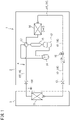
- FIG. 1 is a schematic configuration diagram of a refrigeration apparatus including a refrigerant pipe according to a first embodiment.
- a refrigeration apparatus 1 is, for example, an air conditioner that adjusts indoor temperature and humidity, and includes an outdoor unit 2 installed outdoors and an indoor unit 3 installed indoor.
- the outdoor unit 2 and the indoor unit 3 are connected to each other by a refrigerant pipe 10.
- the refrigeration apparatus 1 includes a refrigerant circuit 4 that performs a vapor compression refrigeration cycle.
- the refrigerant circuit 4 includes a plurality of element components and a refrigerant pipe 10 connecting the plurality of element components.
- the refrigerant circuit 4 includes, as element components, an indoor heat exchanger 11, a compressor 12, a muffler 13, an outdoor heat exchanger 14, an expansion mechanism 15, an accumulator 16, a four-way switching valve 17, shutoff valves 18L and 18G, and the like, which are connected by the refrigerant pipe 10.
- the refrigerant pipe 10 includes a liquid pipe 10L and a gas pipe 10G.
- the liquid pipe 10L and the gas pipe 10G are provided with the shutoff valves 18L and 18G, respectively.
- the indoor heat exchanger 11 is provided in the indoor unit 3 and exchanges heat between refrigerant and indoor air.
- the indoor heat exchanger 11 for example, a cross-fin fin-and-tube heat exchanger, a microchannel heat exchanger, or the like can be adopted.
- An indoor fan (not shown) that blows indoor air to the indoor heat exchanger 11 and sends conditioned air to the room is provided near the indoor heat exchanger 11.
- the compressor 12, the muffler 13, the outdoor heat exchanger 14, the expansion mechanism 15, the accumulator 16, the four-way switching valve 17, and the shutoff valves 18L and 18G are provided in the outdoor unit 2.
- the compressor 12 compresses refrigerant sucked from a suction pipe and discharges the refrigerant from a discharge pipe.
- various compressors such as a scroll compressor can be adopted.
- the muffler 13 suppresses pressure pulsation of the refrigerant discharged from the compressor 12.
- an oil separator may be provided between the discharge pipe of the compressor 12 and the four-way switching valve 17. The oil separator separates lubricating oil from a mixed fluid of the lubricating oil and the refrigerant discharged from the compressor 12.
- the outdoor heat exchanger 14 exchanges heat between the refrigerant and the outdoor air.
- the outdoor heat exchanger 14 for example, a cross-fin fin-and-tube heat exchanger, a microchannel heat exchanger, or the like can be adopted.
- An outdoor fan that sends the outdoor air to the outdoor heat exchanger 14 is provided near the outdoor heat exchanger 14.
- the expansion mechanism 15 is disposed between the outdoor heat exchanger 14 and the indoor heat exchanger 11 in the refrigerant pipe 10 of the refrigerant circuit 4, and expands the inflowing refrigerant to decompress the refrigerant to a predetermined pressure.
- the expansion mechanism 15 for example, an electronic expansion valve with a variable opening degree or a capillary tube can be employed.
- the accumulator 16 is disposed between a suction port of the compressor 12 and the four-way switching valve 17 in the refrigerant circuit 4, and separates the flowing refrigerant into gas and liquid. The gas refrigerant separated in the accumulator 16 is sucked into the compressor 12.
- the four-way switching valve 17 can be switched between a first state indicated by a solid line and a second state indicated by a broken line in FIG. 1 .
- the four-way switching valve 17 is switched to the first state, and when the air conditioner 1 performs a heating operation, the four-way switching valve 17 is switched to the second state.
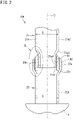
- FIG. 2 is a sectional view illustrating a connected portion between a first pipe and a second pipe of a refrigerant pipe.
- a refrigerant pipe 10A illustrated in FIG. 2 is connected to at least one element component X among the plurality of element components described above.
- the refrigerant pipe 10A includes a first pipe 21 and a second pipe 22.
- the first pipe 21 and the second pipe 22 have an identical axis O.
- the axis O is disposed in an up-down direction (vertical direction).
- a direction along the axis O is also referred to as a "pipe axial direction”.
- a radial direction around the axis O is also referred to as a "pipe radial direction”.
- the first pipe 21 includes a pipe body 21a and a connection pipe 21b.
- the pipe body 21a and the connection pipe 21b are separate members.
- the pipe body 21a includes stainless steel.
- the pipe body 21a includes, for example, SUS304, SUS304L, SUS436L, SUS430, or the like.
- the pipe body 21a has a first large diameter portion 21a2, a first step portion 21a3, and a first small diameter portion 21a1 arranged in the pipe axial direction.
- the first small diameter portion 21a1 is disposed at one end (lower part) of the pipe body 21a in the pipe axial direction.
- the first step portion 21a3 is disposed above the first small diameter portion 21a1.
- the first large diameter portion 21a2 is disposed above the first step portion 21a3.
- the first small diameter portion 21a1 and the first step portion 21a3 are formed by reducing one end in the pipe axial direction of the pipe having an outer diameter D in the pipe radial direction, and a part where a diameter of the pipe is not reduced is defined as the first large diameter portion 21a2.
- the connection pipe 21b includes a material different from a material of the pipe body 21a.
- the connection pipe 21b according to the present embodiment includes copper.
- the "copper” described herein is “pure copper” containing copper as a main component in an amount of 99.9 wt% or more.
- the connection pipe 21b is a straight pipe having a constant outer diameter and inner diameter.
- a length of the connection pipe 21b in the pipe axial direction is shorter than a length of the pipe body 21a in the pipe axial direction.
- the length of the connection pipe 21b in the pipe axial direction is longer than a length of the first small diameter portion 21a1 of the pipe body 21a in the pipe axial direction.
- the inner diameter of the connection pipe 21b is slightly larger than an outer diameter of the first small diameter portion 21a1.
- the first small diameter portion 21a1 of the pipe body 21a is inserted inside the connection pipe 21b in the pipe radial direction.
- An inner peripheral surface of the connection pipe 21b and an outer peripheral surface of the first small diameter portion 21a1 are disposed to face each other in the pipe radial direction.
- the inner peripheral surface of the connection pipe 21b and the outer peripheral surface of the first small diameter portion 21a1 are brazed with a first brazing material B1.
- a thickness of the first brazing material B1 in the pipe radial direction is exaggerated in order to clearly show the brazed portion. The same applies to a second brazing material B2 described later.
- FIG. 3 is an enlarged view of the portion A in FIG. 2 .
- connection pipe 21b and the outer peripheral surface of the first small diameter portion 21a1 are connected to each other by "in-furnace brazing". This is for the following reason.
- a flux for removing the oxide film is required to perform manual brazing (hereinafter, also referred to as "hand brazing") such as torch brazing. Since the refrigerant flows in the refrigerant circuit 4 as a closed circuit, if the flux remains in the refrigerant pipe 10A, the flux may be mixed in the refrigerant, and the mixture may adversely affect performance of the refrigerant or the element component X (for example, the compressor 12) into which the refrigerant flows. Therefore, an operation of removing the flux after brazing is required.
- the stainless steel as a material of the pipe body 21a causes embrittlement called sensitization when heated.
- Sensitization is a phenomenon in which chromium binds to carbon in stainless steel, and the chromium is precipitated at a grain boundary, and thus a part having a low chromium component is generated to reduce corrosion resistance or the like.
- a temperature range in which the sensitization is likely to occur and an application time of the heat are known.
- the in-furnace brazing is a method of performing brazing in a predetermined gas atmosphere, for example, a hydrogen gas atmosphere capable of removing an oxide film inside a continuous furnace or the like. It is therefore possible to braze the stainless steel without using a flux. This eliminates the need for removing the flux after brazing.
- a predetermined gas atmosphere for example, a hydrogen gas atmosphere capable of removing an oxide film inside a continuous furnace or the like.
- it is easy to manage a brazing temperature and a brazing time, and thus the brazing can be performed at a temperature and time that can suppress occurrence of sensitization.
- SUS304L having a smaller carbon amount than SUS304 as the pipe body 21a, sensitization of the pipe body 21a can be suppressed.
- the connection pipe 21b has a protrusion 21b1 protruding in the pipe axial direction from the first small diameter portion 21a1 as an end of the pipe body 21a.
- a protrusion amount T1 of the protrusion 21b1 is, for example, 0.1 mm or more and 25 mm or less.
- the protrusion amount T1 is preferably 1.0 mm or more and 5.0 mm or less.
- the protrusion amount T1 is more preferably 2.0 mm or more and 3.0 mm or less.
- the protrusion amount T1 according to the present embodiment is smaller than an overlap amount R1 of the pipe body 21a and the connection pipe 21b in the pipe radial direction.
- the overlap amount R1 is, for example, 7.0 mm.
- the second pipe 22 is connected to one end of the first pipe 21 in the pipe axial direction.
- the second pipe 22 protrudes from the element component X such as the compressor 12, constitutes a part of the element component X, and constitutes a part of the refrigerant pipe 10A.
- the second pipe 22 according to the present embodiment includes a material different from the pipe body 21a of the first pipe 21 and the same as the connection pipe 21b.
- the second pipe 22 according to the present embodiment includes copper.
- the second pipe 22 has a second large diameter portion 22a, a second step portion 22c, and a second small diameter portion 22b arranged in the pipe axial direction.
- the second large diameter portion 22a is disposed at one end (upper part) of the second pipe 22 in the pipe axial direction.
- the second small diameter portion 22b is disposed at the other end (lower part) of the second pipe 22 in the pipe axial direction.
- a lower end of the second small diameter portion 22b is directly connected to the element component X.
- the second stepped portion 22c is disposed between the second large diameter portion 22a and the second small diameter portion 22b.
- the second large diameter portion 22a and the second step portion 22c are formed by enlarging one end of a pipe having the outer diameter D in the pipe radial direction, and a part where a diameter is not enlarged is defined as the second small diameter portion 22b.
- the second large diameter portion 22a is disposed such that an opening faces upward.
- An inner diameter of the second large diameter portion 22a is slightly larger than the outer diameter of the connection pipe 21b in the first pipe 21.
- the connection pipe 21b of the first pipe 21 is inserted inside the second large diameter portion 22a in the pipe radial direction.
- An inner peripheral surface of the second large diameter portion 22a and an outer peripheral surface of the connection pipe 21b are arranged to face each other in the pipe radial direction.
- the protrusion 21b1 of the connection pipe 21b is in contact with the second step portion 22c of the second pipe 22.
- connection pipe 21b of the first pipe 21 and the second pipe 22, both of which include copper can be easily connected by brazing using an inexpensive brazing material such as phosphor copper brazing.
- the first pipe 21 and the second pipe 22 are relatively positioned in the pipe axial direction by the protrusion 21b1 of the connection pipe 21b being in contact with the second step portion 22c of the second pipe 22. Accordingly, the brazing can be performed more easily.
- connection pipe 21b overlaps the second pipe 22 in the pipe radial direction in a range indicated by R2.
- This overlap amount R2 has substantially the same dimension as the overlap amount R1 between the connection pipe 21b and the pipe body 21a.
- the connection pipe 21b protrudes from the second pipe 22 in the pipe axial direction.
- the protrusion amount T2 of the connection pipe 21b is smaller than the overlap amount R2.
- the protrusion amount T2 is, for example, 2 mm or more and 3 mm or less.
- An overlap amount R3 between the pipe body 21a and the second pipe 22 is, for example, 5.0 mm.
- the connection pipe 21b is placed under a high-temperature environment in a furnace during brazing with the pipe body 21a. Thus, a strength of the connection pipe 21b may decrease due to coarsening of crystal grains of copper.
- the connection pipe 21b having a reduced strength does not exist alone in the refrigerant pipe 10A.
- the connection pipe 21b overlaps at least one of the pipe body 21a or the second pipe 22 in the pipe radial direction. Therefore, a decrease in the strength of the connection pipe 21b is compensated by the pipe body 21a and the second pipe 22.
- connection pipe 21b of the first pipe 21 has the protrusion 21b1 protruding from the pipe body 21a in the pipe axial direction.
- FIG. 3 assuming that the connection pipe 21b is shorter in the pipe axial direction and the connection pipe 21b is retracted upward without protruding from the pipe body 21a, there will be a slight space between the second large diameter portion 22a of a second pipe 22 and the lower end of the first small diameter portion 21a1 of the first pipe 21 in the pipe radial direction, and the overlap amount R2 between a connection pipe 121b and a second pipe 122 will be also reduced. Therefore, there is a possibility that a connection strength between the connection pipe 121b and the second pipe 122 decreases.
- connection pipe 21b since the connection pipe 21b has the protrusion 21b1 protruding from the pipe body 21a in the pipe axial direction, there is no space between the second pipe 22 and the first pipe 21, the overlapping amount R2 between the connection pipe 21b and the second pipe 22 is also increased, and the connection strength between the first pipe 21 and the second pipe 22 can be increased.
- the second brazing material B2 having a melting point lower than a melting point of the first brazing material B2 is used.
- the connection pipe 21b remains connected to the pipe body 21a, and the second pipe 22 of the new element component X can be connected to the connection pipe 21b.
- the first large diameter portion 21a2 of the first pipe 21 and the second small diameter portion 22b of the second pipe 22 have the same outer diameter D. Therefore, in a manufacturing process of the refrigeration apparatus 1, jigs used for fixing, holding, and handling the pipes can be made common. When an inner diameter of the first large diameter portion 21a2 and an inner diameter of the second small diameter portion 22b are common, pressure fluctuation of the refrigerant flowing through the refrigerant pipe 10A can be reduced.
- the pipe body 21a of the first pipe 21 includes stainless steel and has a higher strength than the second pipe 22 including copper. Therefore, a wall thickness of the pipe body 21a can be made thinner than a wall thickness of the second pipe 22.
- the inner diameter of the first large diameter portion 21a2 of the pipe body 21a is larger than the inner diameter of the second small diameter portion 22b of the second pipe 22, it is slightly disadvantageous in terms of suppressing the pressure fluctuation of the refrigerant, but it is possible to reduce a weight of the refrigerant pipe 10A and facilitate processing of the refrigerant pipe 10A.
- FIG. 4 is a sectional view illustrating a connected portion between a first pipe and a second pipe of a refrigerant pipe according to a second embodiment.
- the refrigerant pipe 10A includes a third pipe 23 in addition to the first pipe 21 and the second pipe 22.
- the third pipe 23 has the same axis O as the first pipe 21 and the second pipe 22.
- the first pipe 21 according to the present embodiment is shorter in the pipe axial direction than the first pipe 21 according to the first embodiment.
- the first pipe 21 is disposed between the second pipe 22 and the third pipe 23 in the pipe axial direction. Therefore, the first pipe 21 according to the present embodiment has a function as a joint that connects the second pipe 22 and the third pipe 23 to each other.
- the third pipe 23 is connected to the first large diameter portion 21a2 of the pipe body 21a of the first pipe 21.
- the third pipe 23 includes stainless steel which is the same material as the pipe body 21a.
- the pipe body 21a and the third pipe 23 are connected to teach other by welding such as Tig welding. Alternatively, the pipe body 21a and the third pipe 23 may be connected to each other by brazing.
- the third pipe 23 has a same outer diameter D as the first large diameter portion 21a2 of the pipe body 21a.
- the first pipe 21 in the refrigerant pipe 10A since the first large diameter portion 21a2 of the pipe body 21a is longer in the pipe axial direction, the first pipe 21 increases in size, and is complicated to handle during in-furnace brazing between the pipe body 21a and the connection pipe 21b.
- the pipe body 21a is shorter, and the first pipe 21 itself is used as a "joint" connecting the second pipe 22 and the third pipe 23 to each other.
- the first pipe 21 is downsized, and in-furnace brazing can be easily performed.
- the number of first pipes 21 that can be introduced into the furnace at a time can be increased, and thus production efficiency can be improved.
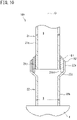
- FIG. 5 is a sectional view illustrating a state before brazing of the pipe body and the connection pipe of the first pipe.
- a ring brazing filler metal Ba to be the first brazing material B1 is fitted to outside of the first small diameter portion 21a1 of the pipe body 21a in the pipe radial direction.
- the connection pipe 21b is fitted to the outside of the first small diameter portion 21a1 in the pipe radial direction, and the ring brazing filler metal Ba is sandwiched between the connection pipe 21b and the first step portion 21a3.
- the pipe body 21a above and the connection pipe 21b below are put into a high-temperature furnace to melt the ring brazing filler metal Ba, and as indicated by an arrow a, the first brazing material B1 is poured into a gap between the outer peripheral surface of the first small diameter portion 21a1 and the inner peripheral surface of the connection pipe 21b.
- brazing can be performed in a state where the connection pipe 21b, the pipe body 21a, and the ring brazing filler metal Ba are relatively positioned.
- first pipe 21 when the first pipe 21 is longer as in the first embodiment, the first pipe 21 can be put into the furnace only in a lateral orientation, but when the first pipe 21 is downsized as in the present embodiment, brazing can be performed in a state where the axis of the first pipe 21 (the pipe body 21a and the connection pipe 21b) is oriented in the up-down direction as described above.
- the first brazing material B1 can be uniformly poured into the gap between the outer peripheral surface of the first small diameter portion 21a1 and the inner peripheral surface of the connection pipe 21b.
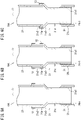
- FIGS. 6A, 6B, and 6C are sectional views illustrating a modification of the pipe body.
- an end 23a of the third pipe 23 is inserted inside the first large diameter portion 21a2 formed in the pipe body 21a of the first pipe 21, and the first large diameter portion 21a2 and the third pipe 23 are connected to each other by welding.
- the pipe body 21a of the first pipe 21 and the third pipe 23 are circumferentially welded at one area in the pipe axial direction, indicated by Y1.
- This welding area Y1 is located at a tip of the first large diameter portion 21a2.
- the welding is performed on an outer periphery of the first large diameter portion 21a2 at the welding area Y1, and then, the first large diameter portion 21a2 and the third pipe 23 are melted and connected to each other.
- the welding area Y1 is located at an end of the first pipe 21 opposite to the second pipe 22 in a range where the pipe body 21a of the first pipe 21 and the third pipe 23 overlap each other in the pipe radial direction.
- the welding area Y1 is located closer to atmosphere (outside of the refrigerant pipe 10A) in the range where the pipe body 21a of the first pipe 21 and the third pipe 23 overlap each other in the pipe radial direction. Therefore, the welding can be easily performed while a connection state between the pipe body 21a of the first pipe 21 and the third pipe 23 are confirmed.
- a region of welding can be widened, a strength of a connected portion between the pipe body 21a and the third pipe 23 can be increased, and a structure withstanding large stress can be obtained.
- the pipe body 21a of the first pipe 21 and the third pipe 23 are circumferentially welded at two areas in the pipe axial direction, indicated by Y1 and Y2. These welding areas Y1 and Y2 are located at both ends of the first large diameter portion 21a2 in the pipe axial direction.
- the end 23a of the third pipe 23 is inserted inside the first large diameter portion 21a2 formed in the pipe body 21a of the first pipe 21, and the first large diameter portion 21a2 and the third pipe 23 are connected to each other by welding.
- the first large diameter portion 21a2 according to the present modification is shorter in the pipe axial direction than the first large diameter portion 21a2 illustrated in FIG. 6A , and the pipe body 21a of the first pipe 21 and the third pipe 23 are welded to each other circumferentially at one area Y3 in the pipe axial direction.
- the first large diameter portion 21a2 since the first large diameter portion 21a2 is shorter, an entire range of the first large diameter portion 21a2 in the pipe axial direction can be connected to the third pipe 23 by welding at one location Y3.
- the end of the connection pipe 21b may abut on the first step portion 21a3 to position the connection pipe 21b in the pipe axial direction with respect to the pipe body 21a.
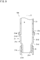
- FIGS. 7A to 9 are sectional views illustrating further modifications of the pipe body.
- the pipe body 21a of the first pipe 21 is constituted by a straight pipe having a constant outer diameter.
- the third pipe 23 includes a third small diameter portion 23a1, a third large diameter portion 23a2, and a third step portion 23a3.
- the third small diameter portion 23a1 is disposed at the end of the third pipe 23 and is inserted into the pipe body 21a.
- the pipe body 21a and the third pipe 23 are circumferentially welded at one area Y4 in the pipe axial direction. This welding is performed over an entire range of the third small diameter portion 23a1 in the pipe axial direction.
- the pipe body 21a of the first pipe 21 is constituted by a straight pipe having a constant outer diameter.
- the third pipe 23 is also constituted by a straight pipe having at least an end whose outer diameter is the same as the pipe body 21a.
- the pipe body 21a and the third pipe 23 are welded on a butted surface Y5.
- a fourth large diameter portion 21a4 having a diameter larger than the diameter of the first large diameter portion 21a2 and a fourth step portion 21a5 disposed between the first large diameter portion 21a2 and the fourth large diameter portion 21a4 are formed in the pipe body 21a of the first pipe 21.
- the end of the third pipe 23 is inserted into the fourth large diameter portion 21a4, and the fourth large diameter portion 21a4 and the third pipe 23 are connected to each other by welding.
- the fourth large diameter portion 21a4 of the first pipe 21 and the third pipe 23 are circumferentially welded at one area, indicated by Y1 in the pipe axial direction.
- the welding area Y1 is located at a tip of the fourth large diameter portion 21a4. The welding is performed on an outer periphery of the fourth large diameter portion 21a4 at the welding area Y1, and then, the fourth large diameter portion 21a4 and the third pipe 23 are melted and connected to each other.
- the welding area Y1 is located at an end of the first pipe 21 opposite to the second pipe 22 in a range where the pipe body 21a of the first pipe 21 and the third pipe 23 overlap each other in the pipe radial direction.
- the welding area Y1 is located closer to atmosphere (outside of the refrigerant pipe 10A) in the range where the pipe body 21a of the first pipe 21 and the third pipe 23 overlap each other in the pipe radial direction. Therefore, the welding can be easily performed while a connection state between the pipe body 21a of the first pipe 21 and the third pipe 23 are confirmed.
- a region of welding can be widened, a strength of a connected portion between the pipe body 21a and the third pipe can be increased, and a structure withstanding large stress can be obtained.
- the pipe body 21a of the first pipe 21 and the third pipe 23 are circumferentially welded at two areas in the pipe axial direction, indicated by Y1 and Y2. These welding areas Y1 and Y2 are located at both ends of the fourth large diameter portion 21a4 in the pipe axial direction.
- the fourth large diameter portion 21a4 and the fourth step portion 21a5 are formed in the pipe body 21a of the first pipe 21.
- the third pipe 23 is inserted into the fourth large diameter portion 21a4, and the fourth large diameter portion 21a4 and the third pipe 23 are connected to each other by welding.
- the fourth large diameter portion 21a4 according to the present modification is shorter in the pipe axial direction than the fourth large diameter portion 21a4 illustrated in FIGS. 8A and 8B , and the first pipe 21 and the third pipe 23 are welded to each other circumferentially at one area Y3 in the pipe axial direction.
- the fourth large diameter portion 21a4 since the fourth large diameter portion 21a4 is shorter, an entire range of the fourth large diameter portion 21a4 in the pipe axial direction can be connected to the third pipe 23 by welding at one location Y3.
- FIG. 10 is a sectional view illustrating a connected portion between a first pipe and a second pipe of a refrigerant pipe according to a third embodiment.
- a structure of the first pipe 21 is different from the first embodiment.
- the pipe body 21a of the first pipe 21 has a constant inner diameter and outer diameter D, and does not include the first large diameter portion, the first small diameter portion, and the first step portion as in the first embodiment.
- the present embodiment produces functional effects substantially similar to those of the first embodiment. Since the first small diameter portion 21a1 is unnecessary in the first pipe 21, there is an advantage that processing is facilitated. However, in the present embodiment, it is necessary to enlarge the outer diameter of the second large diameter portion 22a of the second pipe 22 to be larger than in the first embodiment, and it becomes difficult to process the second pipe 22. In this respect, the first embodiment is more advantageous.
- FIG. 11 is a sectional view illustrating a connected portion between a first pipe and a second pipe of a refrigerant pipe according to a fourth embodiment.
- a structure of the first pipe 21 is different from the first embodiment.
- the protrusion amount T1 of the protrusion 21b1 protruding from the pipe body 21a in the pipe axial direction is larger than the overlap amount R1 with the pipe body 21a.
- the protrusion amount T1 of the protrusion 21b1 is larger than the overlap amount R2 of the connection pipe 21b and the second pipe 22 in the pipe axial direction. Therefore, the refrigerant pipe 10A according to the present embodiment has a region R4 in which the connection pipe 21b alone exists midway in the pipe axial direction.
- the present embodiment produces functional effects substantially similar to those of the first embodiment.
- the refrigerant pipe 10A according to the present embodiment has the region R4 in which the connection pipe 21b having a possibility of strength reduction due to in-furnace brazing exists alone, the first embodiment is more advantageous in terms of strength.
- connection pipe 21b of the first pipe 21 and the second pipe 22 include copper.
- these pipes need not include copper, but the material can be appropriately changed.
- the connection pipe 21b of the first pipe 21 and the second pipe 22 can include a copper alloy.
- a copper alloy is an alloy in which other metals or non-metals are added to copper as a main component to improve properties of copper.
- a copper alloy is a member that does not require a flux treatment or the like and is easily brazed.
- the copper alloy for example, a copper alloy containing copper in an amount of 98 wt% or more is employed.
- a copper alloy containing copper in an amount of 99 wt% or more is employed.
- connection pipe 21b of the first pipe 21 and the second pipe 22 only have to include materials having the same main component.
- one of the connection pipe 21b of the first pipe 21 or the second pipe 22 may include copper and the other may include a copper alloy, in addition to a case where both include copper or a case where both include a copper alloy.
- both the connection pipe 21b of the first pipe 21 and the second pipe 22 include a copper alloy, components other than the main component may be different from each other. That is, the connection pipe 21b and the second pipe 22 may include different materials having the same main component. In this case, both can be brazed without using flux.
- connection pipe 21b of the first pipe 21 and the second pipe 22 can include aluminum or an aluminum alloy.
- aluminum is “pure aluminum” containing 99.9 wt% or more of aluminum as a main component.
- the aluminum alloy is an alloy in which other metals or non-metals are added to aluminum as a main component to improve properties of aluminum.
- an aluminum alloy containing 95 wt% or more of aluminum is employed.
- Both the connection pipe 21b of the first pipe 21 and the second pipe 22 may include aluminum, both of the pipes may include an aluminum alloy, or one of the pipes may include aluminum and the other pipe may include an aluminum alloy.
- components other than the main component may be different.
- the materials such as copper, a copper alloy, aluminum, and an aluminum alloy, which are widely used as the second pipe 22 constituting a part of the element component X, can be used to form the connection pipe 21b of the first pipe 21 and then produce the refrigerant pipe 10A having high versatility in terms of connection with the second pipe 22.
- the second pipe 22 may simply constitute only the refrigerant pipe 10A.
- the first pipe 21 may constitute a part of the element component X.
- the refrigerant pipe 10A includes the first pipe 21 and the second pipe 22.
- the first pipe 21 includes the pipe body 21a including stainless steel and the connection pipe 21b provided at an end of the pipe body 21a in the pipe axial direction and including a material different from stainless steel.
- the connection pipe 21b has the protrusion 21b1 protruding in the pipe axial direction from the end of the pipe body 21a.
- the second pipe 22 includes the same material as the connection pipe 21b.
- the second pipe 22 includes the second large diameter portion 22a disposed at an end in the pipe axial direction, the second small diameter portion 22b having a diameter smaller than the second large diameter portion 22a, and the second step portion 22c disposed between the second large diameter portion 22a and the second small diameter portion 22b.
- the connection pipe 21b is inserted into the second large diameter portion 22a.
- the protrusion 21b1 is in contact with the second step portion 22c.
- the outer peripheral surface of the connection pipe 21b is connected to the inner peripheral surface of the second large diameter
- refrigerant pipe 10A having the above configuration, brazing of stainless steel is unnecessary for connection between the first pipe 21 and the second pipe 22, and the first pipe 21 and the second pipe 22 can be easily connected.
- the stainless steel as the material of the pipe body 21a of the first pipe 21 is less expensive than copper or the like as the material of the second pipe 22. Therefore, the refrigerant pipe 10A according to the embodiments can be produced at a lower cost than a refrigerant pipe as a whole including copper.
- the refrigerant pipe 10A includes the first pipe 21 and the second pipe 22, and the first pipe 21 includes the pipe body 21a including stainless steel and the connection pipe 21b provided at an end of the pipe body 21a in the pipe axial direction and including a material different from stainless steel.
- the connection pipe 21b has the protrusion 21b1 protruding in the pipe axial direction from the end of the pipe body 21a.
- the second pipe 22 includes a material having the same main component as the main component of the material of the connection pipe 21b, and includes the second large diameter portion 22a disposed at an end in the pipe axial direction, the second small diameter portion 22b having a diameter smaller than the second large diameter portion 22a, and the second step portion 22c disposed between the second large diameter portion 22a and the second small diameter portion 22b.
- the connection pipe 21b is inserted into the second large diameter portion 22a.
- the protrusion 21b1 is in contact with the second step portion 22c.
- the outer peripheral surface of the connection pipe 21b is connected to the inner peripheral surface of the second large diameter portion 22a.
- refrigerant pipe 10A having the above configuration, brazing of stainless steel is unnecessary for connection between the first pipe 21 and the second pipe 22, and the first pipe 21 and the second pipe 22 can be easily connected.
- the stainless steel as the material of the pipe body 21a of the first pipe 21 is less expensive than copper or the like as the material of the second pipe 22. Therefore, the refrigerant pipe 10A according to the embodiments can be produced at a lower cost than a refrigerant pipe as a whole including copper.
- connection pipe 21b and the second pipe 22 include different materials having the same main component.
- the first pipe and the second pipe can be still connected to each other easily.
- connection pipe 21b and the second pipe 22 include any one of copper, a copper alloy, aluminum, or an aluminum alloy. Therefore, the first pipe 21 and the second pipe 22 can be easily connected by brazing using an inexpensive brazing material.
- the end of the pipe body 21a and the second large diameter portion 22a are disposed to overlap each other in the pipe radial direction. Therefore, in the refrigerant pipe 10A, the connection pipe 21b that may be reduced in strength due to in-furnace brazing does not exist alone, and the pipe body 21a and the second pipe 22 can compensate for the strength reduction of the connection pipe 21b.
- the pipe body 21a of the first pipe 21 includes the first small diameter portion 21a1 and the first large diameter portion 21a2 having a diameter larger than a diameter of the first small diameter portion 21a1, and the connection pipe 21b is provided on the outer peripheral surface of the first small diameter portion 21a1. Therefore, as compared with a case where the pipe body 21a of the first pipe 21 is a straight pipe having a constant inner diameter and outer diameter (in the second embodiment), the diameter of the second large diameter portion 22a of the second pipe 22 does not need to be large in the pipe radial direction, and the processing of the second pipe 22 can be facilitated.
- the second small diameter portion 22b of the second pipe 22 and the first large diameter portion 21a2 of the pipe body 21a have the same outer diameter D. Therefore, when the first pipe 21 and the second pipe 22 are connected by brazing or the like or bent in the manufacturing process of the refrigeration apparatus 1, jigs used for fixing, holding, and handling the pipes can be made common.
- the second small diameter portion 22b of the second pipe 22 and the first large diameter portion 21a2 of the pipe body 21a have a same inner diameter. Therefore, pressure fluctuation of the refrigerant flowing through the refrigerant pipe 10A can be reduced.
- the opening of the second large diameter portion 22a of the second pipe 22 is disposed to face upward. Therefore, the second brazing material B2 can be easily poured between the inner peripheral surface of the second large diameter portion 22a of the second pipe 22 and the outer peripheral surface of the connection pipe 21b of the first pipe 21, and the connection between the first pipe 21 and the second pipe 22 can be facilitated.
- the first pipe 21 constitutes a joint that connects the second pipe 22 and another pipe 23 including stainless steel to each other. It is therefore possible to downsize the first pipe 21 and facilitate an operation of providing the connection pipe 21b in the pipe body 21a.
Landscapes
- Engineering & Computer Science (AREA)
- General Engineering & Computer Science (AREA)
- Mechanical Engineering (AREA)
- Physics & Mathematics (AREA)
- Thermal Sciences (AREA)
- Fluid Mechanics (AREA)
- Chemical & Material Sciences (AREA)
- Materials Engineering (AREA)
- Branch Pipes, Bends, And The Like (AREA)
- Non-Disconnectible Joints And Screw-Threaded Joints (AREA)
- Other Air-Conditioning Systems (AREA)
- Heat-Exchange Devices With Radiators And Conduit Assemblies (AREA)
Abstract
Description
- The present disclosure relates to a refrigerant pipe and a refrigeration apparatus.
- A heat-pump refrigeration apparatus such as an air conditioner includes a refrigerant circuit formed by connecting, with a refrigerant pipe, element components such as a compressor, an oil separator, a four-way switching valve, a heat source-side heat exchanger, an expansion mechanism, a usage-side heat exchanger, an accumulator, and a shutoff valve. In general, a copper pipe is used for the refrigerant pipe. However, since a material cost of a copper pipe is high, it is considered to use a relatively inexpensive stainless steel refrigerant pipe (see, for example, Patent Literature 1).
- Patent Literature 1:
Japanese Unexamined Patent Publication No. 2010-151327 - When a refrigerant pipe including stainless steel is used as a part of the refrigerant circuit, an operation of manually brazing the refrigerant pipe including stainless steel and the refrigerant pipe including copper may occur during manufacturing the refrigeration apparatus or during maintenance such as part replacement. However, brazing of a stainless steel refrigerant pipe requires work such as removal of an oxide film on a surface, and thus the work becomes complicated.
- An object of the present disclosure is to facilitate connection between a refrigerant pipe including stainless steel and a refrigerant pipe including a material other than stainless steel.
- (1) A refrigerant pipe of the present disclosure constitutes a refrigerant circuit of a refrigeration apparatus, the refrigerant pipe including a first pipe and a second pipe, in which the first pipe includes a pipe body including stainless steel and a connection pipe provided at an end of the pipe body in a pipe axial direction and including a material different from stainless steel, the connection pipe has a protrusion protruding in the pipe axial direction from the end of the pipe body, the second pipe includes a second large diameter portion including a material that is same as the material of the connection pipe and disposed at an end in the pipe axial direction, a second small diameter portion having a smaller diameter than the second large diameter portion, and a step portion disposed between the second large diameter portion and the second small diameter portion, the connection pipe is inserted into the second large diameter portion, the protrusion is in contact with the step portion, and the connection pipe has an outer peripheral surface connected to an inner peripheral surface of the second large diameter portion.
- In this configuration, the first pipe of the refrigerant pipe includes the pipe body including stainless steel and the connection pipe provided at the end of the pipe body and including a material different from stainless steel, and the second pipe including a material that is same as the material of the connection pipe is connected to the connection pipe. Therefore, brazing of stainless steel is unnecessary, and the first pipe and the second pipe can be easily connected.
- (2) A refrigerant pipe of the present disclosure constitutes a refrigerant circuit of a refrigeration apparatus, the refrigerant pipe including a first pipe and a second pipe, in which the first pipe includes a pipe body including stainless steel and a connection pipe provided at an end of the pipe body in a pipe axial direction and including a material different from stainless steel, the connection pipe has a protrusion protruding in the pipe axial direction from the end of the pipe body, the second pipe includes a second large diameter portion including a material whose main component is same as a main component of the material of the connection pipe and disposed at an end in the pipe axial direction, a second small diameter portion having a smaller diameter than the second large diameter portion, and a step portion disposed between the second large diameter portion and the second small diameter portion, the connection pipe is inserted into the second large diameter portion, the protrusion is in contact with the step portion, and the connection pipe has an outer peripheral surface connected to an inner peripheral surface of the second large diameter portion.
- In this configuration, the first pipe of the refrigerant pipe includes the pipe body including stainless steel and the connection pipe provided at the end of the pipe body and including a material different from stainless steel, and the second pipe including a material whose main component is same as the main component of the material of the connection pipe is connected to the connection pipe. Therefore, brazing of stainless steel is unnecessary, and the first pipe and the second pipe can be easily connected.
- (3) The connection pipe and the second pipe preferably include different materials having the same main component.
- As described above, when a connection and the second pipe include different materials having the same main component, the first pipe and the second pipe can be still easily connected.
- (4) The connection pipe and the second pipe preferably include any of copper, a copper alloy, aluminum, or an aluminum alloy.
- In this configuration, the connection pipe and the second pipe can be easily connected by brazing using an inexpensive brazing material.
- (5) The end of the pipe body and the second large diameter portion are preferably disposed to overlap each other in a pipe radial direction.
- In this configuration, in the first pipe, the pipe body including stainless steel and the connection pipe including a material other than stainless steel can be connected in a high-temperature environment by brazing in a furnace in a hydrogen reduction environment, for example, in order to remove an oxide film of the pipe body. However, when a material other than stainless steel, such as copper is exposed to a high temperature environment, there is a possibility that a strength may be reduced. Therefore, by overlapping the pipe body including stainless steel and the second pipe in the pipe radial direction, the connection pipe having reduced strength does not exist alone in the refrigerant pipe, and the pipe body and the second pipe can compensate for the strength decrease of the connection pipe.
- (6) Preferably, the pipe body includes a first small diameter portion and a first large diameter portion having a larger diameter than the first small diameter portion, and the connection pipe is provided on an outer peripheral surface of the first small diameter portion.
- (7) The second small diameter portion of the second pipe and the first large diameter portion of the pipe body preferably have a same outer diameter.
- In a manufacturing process of the refrigeration apparatus, when the refrigerant pipe is connected by brazing, is bent or the like, the refrigerant pipe may be fixed or held using a jig in some cases. As described above, by making the first large diameter portion of the first pipe and the second small diameter portion of the second pipe have the same outer diameter, it is possible to fix the first large diameter portion of the first pipe and the second small diameter portion of the second pipe using a common jig, and to facilitate manufacturing.
- (8) The second small diameter portion of the second pipe and the first large diameter portion of the pipe body preferably have a same inner diameter.
- This configuration can suppress pressure fluctuation of a refrigerant flowing in the refrigerant pipe.
- (9) The second large diameter portion of the second pipe preferably has an opening disposed to face upward.
- In this configuration, the brazing material can be easily poured between the inner peripheral surface of the second large diameter portion of the second pipe and the outer peripheral surface of the connection pipe of the first pipe, and the connection between the first pipe and the second pipe can be facilitated.
- (10) The second pipe is preferably provided in an element component constituting the refrigerant circuit.
- (11) The element component is preferably a compressor.
- (12) The first pipe preferably constitutes a joint that connects the second pipe and another pipe including stainless steel to each other.
- This configuration can downsize the first pipe and facilitate an operation of providing a connection in the pipe body.
- (13) A refrigeration apparatus of the present disclosure includes the refrigerant pipe according to any one of (1) to (12) and an element component that constitutes a refrigerant circuit and to which the refrigerant pipe is connected.
-
- [
FIG. 1] FIG. 1 is a schematic configuration diagram of a refrigeration apparatus including a refrigerant pipe according to a first embodiment. - [
FIG. 2] FIG. 2 is a sectional view illustrating a connected portion between a first pipe and a second pipe of the refrigerant pipe. - [
FIG. 3] FIG. 3 is an enlarged sectional view of a portion A inFIG. 2 . - [
FIG. 4] FIG. 4 is a sectional view illustrating a connected portion between a first pipe and a second pipe of a refrigerant pipe according to a second embodiment. - [
FIG. 5] FIG. 5 is a sectional view illustrating a state before brazing of a pipe body and a connection pipe of the first pipe. - [
FIG. 6] FIGS. 6A, 6B, and 6C are sectional views illustrating a modification of the pipe body. - [
FIG. 7] FIGS. 7A and 7B are sectional views illustrating a further modification of the pipe body. - [
FIG. 8] FIGS. 8A and 8B are sectional views illustrating a further modification of the pipe body. - [
FIG. 9] FIG. 9 is a sectional view illustrating a further modification of the pipe body. - [
FIG. 10] FIG. 10 is a sectional view illustrating a connected portion between a first pipe and a second pipe of a refrigerant pipe according to a third embodiment. - [
FIG. 11] FIG. 11 is a sectional view illustrating a connected portion between a first pipe and a second pipe of a refrigerant pipe according to a fourth embodiment. - Hereinafter, embodiments of the present disclosure will be described in detail with reference to the accompanying drawings.
- The embodiments of the present invention will be described below with reference to the drawings.
-
FIG. 1 is a schematic configuration diagram of a refrigeration apparatus including a refrigerant pipe according to a first embodiment. - A refrigeration apparatus 1 is, for example, an air conditioner that adjusts indoor temperature and humidity, and includes an
outdoor unit 2 installed outdoors and anindoor unit 3 installed indoor. Theoutdoor unit 2 and theindoor unit 3 are connected to each other by arefrigerant pipe 10. - The refrigeration apparatus 1 includes a
refrigerant circuit 4 that performs a vapor compression refrigeration cycle. Therefrigerant circuit 4 includes a plurality of element components and arefrigerant pipe 10 connecting the plurality of element components. Therefrigerant circuit 4 includes, as element components, anindoor heat exchanger 11, acompressor 12, amuffler 13, anoutdoor heat exchanger 14, anexpansion mechanism 15, anaccumulator 16, a four-way switching valve 17,shutoff valves refrigerant pipe 10. Therefrigerant pipe 10 includes aliquid pipe 10L and agas pipe 10G. Theliquid pipe 10L and thegas pipe 10G are provided with theshutoff valves - The
indoor heat exchanger 11 is provided in theindoor unit 3 and exchanges heat between refrigerant and indoor air. As theindoor heat exchanger 11, for example, a cross-fin fin-and-tube heat exchanger, a microchannel heat exchanger, or the like can be adopted. An indoor fan (not shown) that blows indoor air to theindoor heat exchanger 11 and sends conditioned air to the room is provided near theindoor heat exchanger 11. - The
compressor 12, themuffler 13, theoutdoor heat exchanger 14, theexpansion mechanism 15, theaccumulator 16, the four-way switching valve 17, and theshutoff valves outdoor unit 2. Thecompressor 12 compresses refrigerant sucked from a suction pipe and discharges the refrigerant from a discharge pipe. As thecompressor 12, for example, various compressors such as a scroll compressor can be adopted. - The
muffler 13 suppresses pressure pulsation of the refrigerant discharged from thecompressor 12. Instead of or in addition to themuffler 13, an oil separator may be provided between the discharge pipe of thecompressor 12 and the four-way switching valve 17. The oil separator separates lubricating oil from a mixed fluid of the lubricating oil and the refrigerant discharged from thecompressor 12. - The
outdoor heat exchanger 14 exchanges heat between the refrigerant and the outdoor air. As theoutdoor heat exchanger 14, for example, a cross-fin fin-and-tube heat exchanger, a microchannel heat exchanger, or the like can be adopted. An outdoor fan that sends the outdoor air to theoutdoor heat exchanger 14 is provided near theoutdoor heat exchanger 14. - The
expansion mechanism 15 is disposed between theoutdoor heat exchanger 14 and theindoor heat exchanger 11 in therefrigerant pipe 10 of therefrigerant circuit 4, and expands the inflowing refrigerant to decompress the refrigerant to a predetermined pressure. As theexpansion mechanism 15, for example, an electronic expansion valve with a variable opening degree or a capillary tube can be employed. - The
accumulator 16 is disposed between a suction port of thecompressor 12 and the four-way switching valve 17 in therefrigerant circuit 4, and separates the flowing refrigerant into gas and liquid. The gas refrigerant separated in theaccumulator 16 is sucked into thecompressor 12. - The four-
way switching valve 17 can be switched between a first state indicated by a solid line and a second state indicated by a broken line inFIG. 1 . When the air conditioner 1 performs a cooling operation, the four-way switching valve 17 is switched to the first state, and when the air conditioner 1 performs a heating operation, the four-way switching valve 17 is switched to the second state. -
FIG. 2 is a sectional view illustrating a connected portion between a first pipe and a second pipe of a refrigerant pipe. - A
refrigerant pipe 10A illustrated inFIG. 2 is connected to at least one element component X among the plurality of element components described above. Therefrigerant pipe 10A includes afirst pipe 21 and asecond pipe 22. Thefirst pipe 21 and thesecond pipe 22 have an identical axis O. In the present embodiment, the axis O is disposed in an up-down direction (vertical direction). In the following description, a direction along the axis O is also referred to as a "pipe axial direction". A radial direction around the axis O is also referred to as a "pipe radial direction". - The
first pipe 21 includes apipe body 21a and aconnection pipe 21b. Thepipe body 21a and theconnection pipe 21b are separate members. - The
pipe body 21a includes stainless steel. Thepipe body 21a includes, for example, SUS304, SUS304L, SUS436L, SUS430, or the like. - The
pipe body 21a has a first large diameter portion 21a2, a first step portion 21a3, and a first small diameter portion 21a1 arranged in the pipe axial direction. In an example illustrated inFIG. 2 , the first small diameter portion 21a1 is disposed at one end (lower part) of thepipe body 21a in the pipe axial direction. The first step portion 21a3 is disposed above the first small diameter portion 21a1. The first large diameter portion 21a2 is disposed above the first step portion 21a3. - In the
pipe body 21a, the first small diameter portion 21a1 and the first step portion 21a3 are formed by reducing one end in the pipe axial direction of the pipe having an outer diameter D in the pipe radial direction, and a part where a diameter of the pipe is not reduced is defined as the first large diameter portion 21a2. - The
connection pipe 21b includes a material different from a material of thepipe body 21a. Theconnection pipe 21b according to the present embodiment includes copper. The "copper" described herein is "pure copper" containing copper as a main component in an amount of 99.9 wt% or more. Theconnection pipe 21b is a straight pipe having a constant outer diameter and inner diameter. A length of theconnection pipe 21b in the pipe axial direction is shorter than a length of thepipe body 21a in the pipe axial direction. The length of theconnection pipe 21b in the pipe axial direction is longer than a length of the first small diameter portion 21a1 of thepipe body 21a in the pipe axial direction. The inner diameter of theconnection pipe 21b is slightly larger than an outer diameter of the first small diameter portion 21a1. - The first small diameter portion 21a1 of the
pipe body 21a is inserted inside theconnection pipe 21b in the pipe radial direction. An inner peripheral surface of theconnection pipe 21b and an outer peripheral surface of the first small diameter portion 21a1 are disposed to face each other in the pipe radial direction. The inner peripheral surface of theconnection pipe 21b and the outer peripheral surface of the first small diameter portion 21a1 are brazed with a first brazing material B1. InFIG. 2 andFIGS. 3 to 11 described below, a thickness of the first brazing material B1 in the pipe radial direction is exaggerated in order to clearly show the brazed portion. The same applies to a second brazing material B2 described later. -
FIG. 3 is an enlarged view of the portion A inFIG. 2 . - The inner peripheral surface of the
connection pipe 21b and the outer peripheral surface of the first small diameter portion 21a1 are connected to each other by "in-furnace brazing". This is for the following reason. - First, since a passive film (oxide film) is formed on a surface of stainless steel as the material of the
pipe body 21a, a flux for removing the oxide film is required to perform manual brazing (hereinafter, also referred to as "hand brazing") such as torch brazing. Since the refrigerant flows in therefrigerant circuit 4 as a closed circuit, if the flux remains in therefrigerant pipe 10A, the flux may be mixed in the refrigerant, and the mixture may adversely affect performance of the refrigerant or the element component X (for example, the compressor 12) into which the refrigerant flows. Therefore, an operation of removing the flux after brazing is required. - The stainless steel as a material of the
pipe body 21a causes embrittlement called sensitization when heated. Sensitization is a phenomenon in which chromium binds to carbon in stainless steel, and the chromium is precipitated at a grain boundary, and thus a part having a low chromium component is generated to reduce corrosion resistance or the like. A temperature range in which the sensitization is likely to occur and an application time of the heat are known. - The in-furnace brazing is a method of performing brazing in a predetermined gas atmosphere, for example, a hydrogen gas atmosphere capable of removing an oxide film inside a continuous furnace or the like. It is therefore possible to braze the stainless steel without using a flux. This eliminates the need for removing the flux after brazing. In the in-furnace brazing, it is easy to manage a brazing temperature and a brazing time, and thus the brazing can be performed at a temperature and time that can suppress occurrence of sensitization. By using SUS304L having a smaller carbon amount than SUS304, as the
pipe body 21a, sensitization of thepipe body 21a can be suppressed. - The
connection pipe 21b has a protrusion 21b1 protruding in the pipe axial direction from the first small diameter portion 21a1 as an end of thepipe body 21a. A protrusion amount T1 of the protrusion 21b1 is, for example, 0.1 mm or more and 25 mm or less. The protrusion amount T1 is preferably 1.0 mm or more and 5.0 mm or less. The protrusion amount T1 is more preferably 2.0 mm or more and 3.0 mm or less. The protrusion amount T1 according to the present embodiment is smaller than an overlap amount R1 of thepipe body 21a and theconnection pipe 21b in the pipe radial direction. The overlap amount R1 is, for example, 7.0 mm. - As illustrated in
FIGS. 2 and3 , thesecond pipe 22 is connected to one end of thefirst pipe 21 in the pipe axial direction. Thesecond pipe 22 protrudes from the element component X such as thecompressor 12, constitutes a part of the element component X, and constitutes a part of therefrigerant pipe 10A. Thesecond pipe 22 according to the present embodiment includes a material different from thepipe body 21a of thefirst pipe 21 and the same as theconnection pipe 21b. Thesecond pipe 22 according to the present embodiment includes copper. - The
second pipe 22 has a secondlarge diameter portion 22a, asecond step portion 22c, and a secondsmall diameter portion 22b arranged in the pipe axial direction. The secondlarge diameter portion 22a is disposed at one end (upper part) of thesecond pipe 22 in the pipe axial direction. The secondsmall diameter portion 22b is disposed at the other end (lower part) of thesecond pipe 22 in the pipe axial direction. A lower end of the secondsmall diameter portion 22b is directly connected to the element component X. The second steppedportion 22c is disposed between the secondlarge diameter portion 22a and the secondsmall diameter portion 22b. - In the
second pipe 22, the secondlarge diameter portion 22a and thesecond step portion 22c are formed by enlarging one end of a pipe having the outer diameter D in the pipe radial direction, and a part where a diameter is not enlarged is defined as the secondsmall diameter portion 22b. - The second
large diameter portion 22a is disposed such that an opening faces upward. An inner diameter of the secondlarge diameter portion 22a is slightly larger than the outer diameter of theconnection pipe 21b in thefirst pipe 21. Theconnection pipe 21b of thefirst pipe 21 is inserted inside the secondlarge diameter portion 22a in the pipe radial direction. An inner peripheral surface of the secondlarge diameter portion 22a and an outer peripheral surface of theconnection pipe 21b are arranged to face each other in the pipe radial direction. The protrusion 21b1 of theconnection pipe 21b is in contact with thesecond step portion 22c of thesecond pipe 22. - The inner peripheral surface of the second
large diameter portion 22a and the outer peripheral surface of theconnection pipe 21b are brazed with the second brazing material B2. This brazing is manual brazing such as torch brazing (burner brazing). Since theconnection pipe 21b of thefirst pipe 21 and thesecond pipe 22, both of which include copper, can be easily connected by brazing using an inexpensive brazing material such as phosphor copper brazing. - The
first pipe 21 and thesecond pipe 22 are relatively positioned in the pipe axial direction by the protrusion 21b1 of theconnection pipe 21b being in contact with thesecond step portion 22c of thesecond pipe 22. Accordingly, the brazing can be performed more easily. - As illustrated in
FIG. 3 , theconnection pipe 21b overlaps thesecond pipe 22 in the pipe radial direction in a range indicated by R2. This overlap amount R2 has substantially the same dimension as the overlap amount R1 between theconnection pipe 21b and thepipe body 21a. Theconnection pipe 21b protrudes from thesecond pipe 22 in the pipe axial direction. The protrusion amount T2 of theconnection pipe 21b is smaller than the overlap amount R2. The protrusion amount T2 is, for example, 2 mm or more and 3 mm or less. - A lower end of the
pipe body 21a of thefirst pipe 21 and an upper end of thesecond pipe 22 overlap each other in the pipe radial direction. An overlap amount R3 between thepipe body 21a and thesecond pipe 22 is, for example, 5.0 mm. Theconnection pipe 21b is placed under a high-temperature environment in a furnace during brazing with thepipe body 21a. Thus, a strength of theconnection pipe 21b may decrease due to coarsening of crystal grains of copper. In the present embodiment, since thepipe body 21a and thesecond pipe 22 are disposed to overlap each other in the pipe radial direction, theconnection pipe 21b having a reduced strength does not exist alone in therefrigerant pipe 10A. In other words, theconnection pipe 21b overlaps at least one of thepipe body 21a or thesecond pipe 22 in the pipe radial direction. Therefore, a decrease in the strength of theconnection pipe 21b is compensated by thepipe body 21a and thesecond pipe 22. - In the present embodiment, the
connection pipe 21b of thefirst pipe 21 has the protrusion 21b1 protruding from thepipe body 21a in the pipe axial direction. However, inFIG. 3 , assuming that theconnection pipe 21b is shorter in the pipe axial direction and theconnection pipe 21b is retracted upward without protruding from thepipe body 21a, there will be a slight space between the secondlarge diameter portion 22a of asecond pipe 22 and the lower end of the first small diameter portion 21a1 of thefirst pipe 21 in the pipe radial direction, and the overlap amount R2 between a connection pipe 121b and a second pipe 122 will be also reduced. Therefore, there is a possibility that a connection strength between the connection pipe 121b and the second pipe 122 decreases. - In the present embodiment, as shown in
FIG. 3 , since theconnection pipe 21b has the protrusion 21b1 protruding from thepipe body 21a in the pipe axial direction, there is no space between thesecond pipe 22 and thefirst pipe 21, the overlapping amount R2 between theconnection pipe 21b and thesecond pipe 22 is also increased, and the connection strength between thefirst pipe 21 and thesecond pipe 22 can be increased. - The second brazing material B2 having a melting point lower than a melting point of the first brazing material B2 is used. Thus, for example, when the element component X is replaced, by heating the connected portion between the
first pipe 21 and thesecond pipe 22 at a temperature higher than the melting point of the second brazing material B2 and lower than the melting point of the first brazing material B1, only the second brazing material B2 is melted without melting the first brazing material B1, and thesecond pipe 22 can be removed from thefirst pipe 21. Therefore, in thefirst pipe 21, theconnection pipe 21b remains connected to thepipe body 21a, and thesecond pipe 22 of the new element component X can be connected to theconnection pipe 21b. - The first large diameter portion 21a2 of the
first pipe 21 and the secondsmall diameter portion 22b of thesecond pipe 22 have the same outer diameter D. Therefore, in a manufacturing process of the refrigeration apparatus 1, jigs used for fixing, holding, and handling the pipes can be made common. When an inner diameter of the first large diameter portion 21a2 and an inner diameter of the secondsmall diameter portion 22b are common, pressure fluctuation of the refrigerant flowing through therefrigerant pipe 10A can be reduced. - The
pipe body 21a of thefirst pipe 21 includes stainless steel and has a higher strength than thesecond pipe 22 including copper. Therefore, a wall thickness of thepipe body 21a can be made thinner than a wall thickness of thesecond pipe 22. In this case, since the inner diameter of the first large diameter portion 21a2 of thepipe body 21a is larger than the inner diameter of the secondsmall diameter portion 22b of thesecond pipe 22, it is slightly disadvantageous in terms of suppressing the pressure fluctuation of the refrigerant, but it is possible to reduce a weight of therefrigerant pipe 10A and facilitate processing of therefrigerant pipe 10A. -
FIG. 4 is a sectional view illustrating a connected portion between a first pipe and a second pipe of a refrigerant pipe according to a second embodiment. - The
refrigerant pipe 10A according to the present embodiment includes athird pipe 23 in addition to thefirst pipe 21 and thesecond pipe 22. Thethird pipe 23 has the same axis O as thefirst pipe 21 and thesecond pipe 22. - The
first pipe 21 according to the present embodiment is shorter in the pipe axial direction than thefirst pipe 21 according to the first embodiment. Thefirst pipe 21 is disposed between thesecond pipe 22 and thethird pipe 23 in the pipe axial direction. Therefore, thefirst pipe 21 according to the present embodiment has a function as a joint that connects thesecond pipe 22 and thethird pipe 23 to each other. - The
third pipe 23 is connected to the first large diameter portion 21a2 of thepipe body 21a of thefirst pipe 21. Thethird pipe 23 includes stainless steel which is the same material as thepipe body 21a. Thepipe body 21a and thethird pipe 23 are connected to teach other by welding such as Tig welding. Alternatively, thepipe body 21a and thethird pipe 23 may be connected to each other by brazing. Thethird pipe 23 has a same outer diameter D as the first large diameter portion 21a2 of thepipe body 21a. - In the
first pipe 21 in therefrigerant pipe 10A according to the first embodiment, since the first large diameter portion 21a2 of thepipe body 21a is longer in the pipe axial direction, thefirst pipe 21 increases in size, and is complicated to handle during in-furnace brazing between thepipe body 21a and theconnection pipe 21b. In thefirst pipe 21 according to the present embodiment, thepipe body 21a is shorter, and thefirst pipe 21 itself is used as a "joint" connecting thesecond pipe 22 and thethird pipe 23 to each other. Thus, thefirst pipe 21 is downsized, and in-furnace brazing can be easily performed. In addition, by downsizing thefirst pipe 21, the number offirst pipes 21 that can be introduced into the furnace at a time can be increased, and thus production efficiency can be improved. -
FIG. 5 is a sectional view illustrating a state before brazing of the pipe body and the connection pipe of the first pipe. - In the present embodiment, in order to braze the
pipe body 21a and theconnection pipe 21b, first, a ring brazing filler metal Ba to be the first brazing material B1 is fitted to outside of the first small diameter portion 21a1 of thepipe body 21a in the pipe radial direction. Next, theconnection pipe 21b is fitted to the outside of the first small diameter portion 21a1 in the pipe radial direction, and the ring brazing filler metal Ba is sandwiched between theconnection pipe 21b and the first step portion 21a3. With thepipe body 21a above and theconnection pipe 21b below, thepipe body 21a and theconnection pipe 21b are put into a high-temperature furnace to melt the ring brazing filler metal Ba, and as indicated by an arrow a, the first brazing material B1 is poured into a gap between the outer peripheral surface of the first small diameter portion 21a1 and the inner peripheral surface of theconnection pipe 21b. - In this manner, by sandwiching the ring brazing filler metal Ba between the
connection pipe 21b and the first step portion 21a3, brazing can be performed in a state where theconnection pipe 21b, thepipe body 21a, and the ring brazing filler metal Ba are relatively positioned. In addition, when thefirst pipe 21 is longer as in the first embodiment, thefirst pipe 21 can be put into the furnace only in a lateral orientation, but when thefirst pipe 21 is downsized as in the present embodiment, brazing can be performed in a state where the axis of the first pipe 21 (thepipe body 21a and theconnection pipe 21b) is oriented in the up-down direction as described above. Thus, the first brazing material B1 can be uniformly poured into the gap between the outer peripheral surface of the first small diameter portion 21a1 and the inner peripheral surface of theconnection pipe 21b. -
FIGS. 6A, 6B, and 6C are sectional views illustrating a modification of the pipe body. - In the modification illustrated in
FIGS. 6A to 6C , anend 23a of thethird pipe 23 is inserted inside the first large diameter portion 21a2 formed in thepipe body 21a of thefirst pipe 21, and the first large diameter portion 21a2 and thethird pipe 23 are connected to each other by welding. - In an example illustrated in
FIG. 6A , thepipe body 21a of thefirst pipe 21 and thethird pipe 23 are circumferentially welded at one area in the pipe axial direction, indicated by Y1. This welding area Y1 is located at a tip of the first large diameter portion 21a2. The welding is performed on an outer periphery of the first large diameter portion 21a2 at the welding area Y1, and then, the first large diameter portion 21a2 and thethird pipe 23 are melted and connected to each other. - The welding area Y1 is located at an end of the
first pipe 21 opposite to thesecond pipe 22 in a range where thepipe body 21a of thefirst pipe 21 and thethird pipe 23 overlap each other in the pipe radial direction. In other words, the welding area Y1 is located closer to atmosphere (outside of therefrigerant pipe 10A) in the range where thepipe body 21a of thefirst pipe 21 and thethird pipe 23 overlap each other in the pipe radial direction. Therefore, the welding can be easily performed while a connection state between thepipe body 21a of thefirst pipe 21 and thethird pipe 23 are confirmed. Furthermore, as compared with a case where a butted portion between thepipe body 21a and thethird pipe 23 is welded as in the embodiment illustrated inFIG. 4 , in the present modification, a region of welding can be widened, a strength of a connected portion between thepipe body 21a and thethird pipe 23 can be increased, and a structure withstanding large stress can be obtained. - In an example illustrated in
FIG. 6B , thepipe body 21a of thefirst pipe 21 and thethird pipe 23 are circumferentially welded at two areas in the pipe axial direction, indicated by Y1 and Y2. These welding areas Y1 and Y2 are located at both ends of the first large diameter portion 21a2 in the pipe axial direction. - As illustrated in
FIG. 6A , when the first large diameter portion 21a2 and thethird pipe 23 are connected to each other only at the welding area Y1, if a minute movement occurs at theend 23a of thethird pipe 23 due to a flow of the refrigerant in therefrigerant pipe 10A or the like, stress may concentrate near a boundary between the first large diameter portion 21a2 and the first step portion 21a3. Therefore, in the example shown inFIG. 6B , by connecting the first large diameter portion 21a2 and thethird pipe 23 to each other also at the welding area Y2, the movement of thethird pipe 23 can be restricted, and stress concentration generated in thepipe body 21a of thefirst pipe 21 can be suppressed. - In an example illustrated in
FIG. 6C , as in the example illustrated inFIG. 6A , theend 23a of thethird pipe 23 is inserted inside the first large diameter portion 21a2 formed in thepipe body 21a of thefirst pipe 21, and the first large diameter portion 21a2 and thethird pipe 23 are connected to each other by welding. The first large diameter portion 21a2 according to the present modification is shorter in the pipe axial direction than the first large diameter portion 21a2 illustrated inFIG. 6A , and thepipe body 21a of thefirst pipe 21 and thethird pipe 23 are welded to each other circumferentially at one area Y3 in the pipe axial direction. In the present modification, since the first large diameter portion 21a2 is shorter, an entire range of the first large diameter portion 21a2 in the pipe axial direction can be connected to thethird pipe 23 by welding at one location Y3. - In each example shown in
FIGS. 6A to 6C , by forming the first small diameter portion 21a1 of thepipe body 21a shorter in the pipe axial direction or forming theconnection pipe 21b longer in the pipe axial direction, the end of theconnection pipe 21b may abut on the first step portion 21a3 to position theconnection pipe 21b in the pipe axial direction with respect to thepipe body 21a. -
FIGS. 7A to 9 are sectional views illustrating further modifications of the pipe body. - In an example illustrated in
FIG. 7A , thepipe body 21a of thefirst pipe 21 is constituted by a straight pipe having a constant outer diameter. On the other hand, thethird pipe 23 includes a third small diameter portion 23a1, a third large diameter portion 23a2, and a third step portion 23a3. The third small diameter portion 23a1 is disposed at the end of thethird pipe 23 and is inserted into thepipe body 21a. Thepipe body 21a and thethird pipe 23 are circumferentially welded at one area Y4 in the pipe axial direction. This welding is performed over an entire range of the third small diameter portion 23a1 in the pipe axial direction. - In an example illustrated in
FIG. 7B , thepipe body 21a of thefirst pipe 21 is constituted by a straight pipe having a constant outer diameter. Thethird pipe 23 is also constituted by a straight pipe having at least an end whose outer diameter is the same as thepipe body 21a. Thepipe body 21a and thethird pipe 23 are welded on a butted surface Y5. - In the modification illustrated in
FIGS. 8A and 8B , a fourth large diameter portion 21a4 having a diameter larger than the diameter of the first large diameter portion 21a2 and a fourth step portion 21a5 disposed between the first large diameter portion 21a2 and the fourth large diameter portion 21a4 are formed in thepipe body 21a of thefirst pipe 21. The end of thethird pipe 23 is inserted into the fourth large diameter portion 21a4, and the fourth large diameter portion 21a4 and thethird pipe 23 are connected to each other by welding. - In an example illustrated in
FIG. 8A , the fourth large diameter portion 21a4 of thefirst pipe 21 and thethird pipe 23 are circumferentially welded at one area, indicated by Y1 in the pipe axial direction. The welding area Y1 is located at a tip of the fourth large diameter portion 21a4. The welding is performed on an outer periphery of the fourth large diameter portion 21a4 at the welding area Y1, and then, the fourth large diameter portion 21a4 and thethird pipe 23 are melted and connected to each other. - The welding area Y1 is located at an end of the
first pipe 21 opposite to thesecond pipe 22 in a range where thepipe body 21a of thefirst pipe 21 and thethird pipe 23 overlap each other in the pipe radial direction. In other words, the welding area Y1 is located closer to atmosphere (outside of therefrigerant pipe 10A) in the range where thepipe body 21a of thefirst pipe 21 and thethird pipe 23 overlap each other in the pipe radial direction. Therefore, the welding can be easily performed while a connection state between thepipe body 21a of thefirst pipe 21 and thethird pipe 23 are confirmed. Furthermore, as compared with a case where a butted portion between thepipe body 21a and the third pipe is welded as in the embodiment illustrated inFIG. 4 , in the present modification, a region of welding can be widened, a strength of a connected portion between thepipe body 21a and the third pipe can be increased, and a structure withstanding large stress can be obtained. - In an example illustrated in
FIG. 8B , thepipe body 21a of thefirst pipe 21 and thethird pipe 23 are circumferentially welded at two areas in the pipe axial direction, indicated by Y1 and Y2. These welding areas Y1 and Y2 are located at both ends of the fourth large diameter portion 21a4 in the pipe axial direction. - As illustrated in
FIG. 8A , when the fourth large diameter portion 21a4 and thethird pipe 23 are connected to each other only at the welding area Y1, if a minute movement occurs at theend 23a of thethird pipe 23 due to a flow of the refrigerant in therefrigerant pipe 10A or the like, stress may concentrate near a boundary between the fourth large diameter portion 21a4 and the fourth step portion 21a5. Therefore, in the example shown inFIG. 8B , by connecting the fourth large diameter portion 21a4 and thethird pipe 23 to each other also at the welding area Y2, the movement of thethird pipe 23 can be restricted, and stress concentration generated in thefirst pipe 21 can be suppressed. - In an example illustrated in
FIG. 9 , similarly to the example illustrated inFIGS. 8A and 8B , the fourth large diameter portion 21a4 and the fourth step portion 21a5 are formed in thepipe body 21a of thefirst pipe 21. Thethird pipe 23 is inserted into the fourth large diameter portion 21a4, and the fourth large diameter portion 21a4 and thethird pipe 23 are connected to each other by welding. The fourth large diameter portion 21a4 according to the present modification is shorter in the pipe axial direction than the fourth large diameter portion 21a4 illustrated inFIGS. 8A and 8B , and thefirst pipe 21 and thethird pipe 23 are welded to each other circumferentially at one area Y3 in the pipe axial direction. In the present modification, since the fourth large diameter portion 21a4 is shorter, an entire range of the fourth large diameter portion 21a4 in the pipe axial direction can be connected to thethird pipe 23 by welding at one location Y3. -
FIG. 10 is a sectional view illustrating a connected portion between a first pipe and a second pipe of a refrigerant pipe according to a third embodiment. - In the
refrigerant pipe 10A according to the present embodiment, a structure of thefirst pipe 21 is different from the first embodiment. Thepipe body 21a of thefirst pipe 21 has a constant inner diameter and outer diameter D, and does not include the first large diameter portion, the first small diameter portion, and the first step portion as in the first embodiment. - The present embodiment produces functional effects substantially similar to those of the first embodiment. Since the first small diameter portion 21a1 is unnecessary in the
first pipe 21, there is an advantage that processing is facilitated. However, in the present embodiment, it is necessary to enlarge the outer diameter of the secondlarge diameter portion 22a of thesecond pipe 22 to be larger than in the first embodiment, and it becomes difficult to process thesecond pipe 22. In this respect, the first embodiment is more advantageous. -
FIG. 11 is a sectional view illustrating a connected portion between a first pipe and a second pipe of a refrigerant pipe according to a fourth embodiment. - In the
refrigerant pipe 10A according to the present embodiment, a structure of thefirst pipe 21 is different from the first embodiment. In theconnection pipe 21b of thefirst pipe 21, the protrusion amount T1 of the protrusion 21b1 protruding from thepipe body 21a in the pipe axial direction is larger than the overlap amount R1 with thepipe body 21a. The protrusion amount T1 of the protrusion 21b1 is larger than the overlap amount R2 of theconnection pipe 21b and thesecond pipe 22 in the pipe axial direction. Therefore, therefrigerant pipe 10A according to the present embodiment has a region R4 in which theconnection pipe 21b alone exists midway in the pipe axial direction. - The present embodiment produces functional effects substantially similar to those of the first embodiment. However, since the
refrigerant pipe 10A according to the present embodiment has the region R4 in which theconnection pipe 21b having a possibility of strength reduction due to in-furnace brazing exists alone, the first embodiment is more advantageous in terms of strength. - In the embodiments, the
connection pipe 21b of thefirst pipe 21 and thesecond pipe 22 include copper. However, these pipes need not include copper, but the material can be appropriately changed. For example, theconnection pipe 21b of thefirst pipe 21 and thesecond pipe 22 can include a copper alloy. A copper alloy is an alloy in which other metals or non-metals are added to copper as a main component to improve properties of copper. Like copper, a copper alloy is a member that does not require a flux treatment or the like and is easily brazed. As the copper alloy, for example, a copper alloy containing copper in an amount of 98 wt% or more is employed. Preferably, as the copper alloy, a copper alloy containing copper in an amount of 99 wt% or more is employed. - The
connection pipe 21b of thefirst pipe 21 and thesecond pipe 22 only have to include materials having the same main component. Thus, one of theconnection pipe 21b of thefirst pipe 21 or thesecond pipe 22 may include copper and the other may include a copper alloy, in addition to a case where both include copper or a case where both include a copper alloy. When both theconnection pipe 21b of thefirst pipe 21 and thesecond pipe 22 include a copper alloy, components other than the main component may be different from each other. That is, theconnection pipe 21b and thesecond pipe 22 may include different materials having the same main component. In this case, both can be brazed without using flux. - The
connection pipe 21b of thefirst pipe 21 and thesecond pipe 22 can include aluminum or an aluminum alloy. In the present specification, "aluminum" is "pure aluminum" containing 99.9 wt% or more of aluminum as a main component. The aluminum alloy is an alloy in which other metals or non-metals are added to aluminum as a main component to improve properties of aluminum. As the aluminum alloy, for example, an aluminum alloy containing 95 wt% or more of aluminum is employed. Both theconnection pipe 21b of thefirst pipe 21 and thesecond pipe 22 may include aluminum, both of the pipes may include an aluminum alloy, or one of the pipes may include aluminum and the other pipe may include an aluminum alloy. When both theconnection pipe 21b of thefirst pipe 21 and thesecond pipe 22 include an aluminum alloy, components other than the main component may be different. - The materials such as copper, a copper alloy, aluminum, and an aluminum alloy, which are widely used as the
second pipe 22 constituting a part of the element component X, can be used to form theconnection pipe 21b of thefirst pipe 21 and then produce therefrigerant pipe 10A having high versatility in terms of connection with thesecond pipe 22. - Although the
second pipe 22 according to each of the embodiments is provided in the element component X and constitutes a part of the element component X, thesecond pipe 22 may simply constitute only therefrigerant pipe 10A. Thefirst pipe 21 may constitute a part of the element component X. - (1) The
refrigerant pipe 10A according to each of the embodiments includes thefirst pipe 21 and thesecond pipe 22. Thefirst pipe 21 includes thepipe body 21a including stainless steel and theconnection pipe 21b provided at an end of thepipe body 21a in the pipe axial direction and including a material different from stainless steel. Theconnection pipe 21b has the protrusion 21b1 protruding in the pipe axial direction from the end of thepipe body 21a. Thesecond pipe 22 includes the same material as theconnection pipe 21b. Thesecond pipe 22 includes the secondlarge diameter portion 22a disposed at an end in the pipe axial direction, the secondsmall diameter portion 22b having a diameter smaller than the secondlarge diameter portion 22a, and thesecond step portion 22c disposed between the secondlarge diameter portion 22a and the secondsmall diameter portion 22b. Theconnection pipe 21b is inserted into the secondlarge diameter portion 22a. The protrusion 21b1 is in contact with thesecond step portion 22c. The outer peripheral surface of theconnection pipe 21b is connected to the inner peripheral surface of the secondlarge diameter portion 22a. - In
refrigerant pipe 10A having the above configuration, brazing of stainless steel is unnecessary for connection between thefirst pipe 21 and thesecond pipe 22, and thefirst pipe 21 and thesecond pipe 22 can be easily connected. The stainless steel as the material of thepipe body 21a of thefirst pipe 21 is less expensive than copper or the like as the material of thesecond pipe 22. Therefore, therefrigerant pipe 10A according to the embodiments can be produced at a lower cost than a refrigerant pipe as a whole including copper. - (2) The
refrigerant pipe 10A according to the other embodiments described above includes thefirst pipe 21 and thesecond pipe 22, and thefirst pipe 21 includes thepipe body 21a including stainless steel and theconnection pipe 21b provided at an end of thepipe body 21a in the pipe axial direction and including a material different from stainless steel. Theconnection pipe 21b has the protrusion 21b1 protruding in the pipe axial direction from the end of thepipe body 21a. Thesecond pipe 22 includes a material having the same main component as the main component of the material of theconnection pipe 21b, and includes the secondlarge diameter portion 22a disposed at an end in the pipe axial direction, the secondsmall diameter portion 22b having a diameter smaller than the secondlarge diameter portion 22a, and thesecond step portion 22c disposed between the secondlarge diameter portion 22a and the secondsmall diameter portion 22b. Theconnection pipe 21b is inserted into the secondlarge diameter portion 22a. The protrusion 21b1 is in contact with thesecond step portion 22c. The outer peripheral surface of theconnection pipe 21b is connected to the inner peripheral surface of the secondlarge diameter portion 22a. - In
refrigerant pipe 10A having the above configuration, brazing of stainless steel is unnecessary for connection between thefirst pipe 21 and thesecond pipe 22, and thefirst pipe 21 and thesecond pipe 22 can be easily connected. The stainless steel as the material of thepipe body 21a of thefirst pipe 21 is less expensive than copper or the like as the material of thesecond pipe 22. Therefore, therefrigerant pipe 10A according to the embodiments can be produced at a lower cost than a refrigerant pipe as a whole including copper. - (3) In the
refrigerant pipe 10A according to the other embodiments, theconnection pipe 21b and thesecond pipe 22 include different materials having the same main component. - In this case, the first pipe and the second pipe can be still connected to each other easily.
- (4) In the embodiments, the
connection pipe 21b and thesecond pipe 22 include any one of copper, a copper alloy, aluminum, or an aluminum alloy. Therefore, thefirst pipe 21 and thesecond pipe 22 can be easily connected by brazing using an inexpensive brazing material. - (5) In the first and second embodiments, the end of the
pipe body 21a and the secondlarge diameter portion 22a are disposed to overlap each other in the pipe radial direction. Therefore, in therefrigerant pipe 10A, theconnection pipe 21b that may be reduced in strength due to in-furnace brazing does not exist alone, and thepipe body 21a and thesecond pipe 22 can compensate for the strength reduction of theconnection pipe 21b. - (6) In the first and third embodiments, the
pipe body 21a of thefirst pipe 21 includes the first small diameter portion 21a1 and the first large diameter portion 21a2 having a diameter larger than a diameter of the first small diameter portion 21a1, and theconnection pipe 21b is provided on the outer peripheral surface of the first small diameter portion 21a1. Therefore, as compared with a case where thepipe body 21a of thefirst pipe 21 is a straight pipe having a constant inner diameter and outer diameter (in the second embodiment), the diameter of the secondlarge diameter portion 22a of thesecond pipe 22 does not need to be large in the pipe radial direction, and the processing of thesecond pipe 22 can be facilitated. - (7) In the embodiments, the second
small diameter portion 22b of thesecond pipe 22 and the first large diameter portion 21a2 of thepipe body 21a have the same outer diameter D. Therefore, when thefirst pipe 21 and thesecond pipe 22 are connected by brazing or the like or bent in the manufacturing process of the refrigeration apparatus 1, jigs used for fixing, holding, and handling the pipes can be made common. - (8) In the embodiments, the second
small diameter portion 22b of thesecond pipe 22 and the first large diameter portion 21a2 of thepipe body 21a have a same inner diameter. Therefore, pressure fluctuation of the refrigerant flowing through therefrigerant pipe 10A can be reduced. - (9) In the embodiments, the opening of the second
large diameter portion 22a of thesecond pipe 22 is disposed to face upward. Therefore, the second brazing material B2 can be easily poured between the inner peripheral surface of the secondlarge diameter portion 22a of thesecond pipe 22 and the outer peripheral surface of theconnection pipe 21b of thefirst pipe 21, and the connection between thefirst pipe 21 and thesecond pipe 22 can be facilitated. - (10) In the second embodiment, the
first pipe 21 constitutes a joint that connects thesecond pipe 22 and anotherpipe 23 including stainless steel to each other. It is therefore possible to downsize thefirst pipe 21 and facilitate an operation of providing theconnection pipe 21b in thepipe body 21a. - Note that the present disclosure is not limited to the above exemplification, but is indicated by the appended claims and is intended to include all modifications within the scope and meaning equivalent to those of the claims.
-
- 1: REFRIGERATION APPARATUS
- 4: REFRIGERANT CIRCUIT
- 10: REFRIGERANT PIPE
- 10A: REFRIGERANT PIPE
- 12: COMPRESSOR
- 21: FIRST PIPE
- 21a: PIPE BODY
- 21a1: FIRST SMALL DIAMETER PORTION
- 21a2: FIRST LARGE DIAMETER PORTION
- 21a3: FIRST STEP PORTION
- 21b: CONNECTION PIPE
- 21b1: PROTRUSION
- 22: SECOND PIPE
- 22a: SECOND LARGE DIAMETER PORTION
- 22b: SECOND SMALL DIAMETER PORTION
- 23: THIRD PIPE
- D: OUTER DIAMETER
- X: ELEMENT COMPONENT
Claims (13)
- A refrigerant pipe that constitutes a refrigerant circuit (4) of a refrigeration apparatus (1), the refrigerant pipe comprising:a first pipe (21); anda second pipe (22), whereinthe first pipe (21) includes a pipe body (21a) including stainless steel and a connection pipe (21b) provided at an end of the pipe body (21a) in a pipe axial direction and including a material different from stainless steel,the connection pipe (21b) has a protrusion (21b1) protruding in the pipe axial direction from the end of the pipe body (21a),the second pipe (22) includes a second large diameter portion (22a) including a material that is same as the material of the connection pipe (21b) and disposed at an end in the pipe axial direction, a second small diameter portion (22b) having a smaller diameter than the second large diameter portion (22a), and a step portion (22c) disposed between the second large diameter portion (22a) and the second small diameter portion (22b),the connection pipe (21b) is inserted into the second large diameter portion (22a),the protrusion (21b1) is in contact with the step portion (22c), andthe connection pipe (21b) has an outer peripheral surface connected to an inner peripheral surface of the second large diameter portion (22a).
- A refrigerant pipe that constitutes a refrigerant circuit (4) of a refrigeration apparatus (1), the refrigerant pipe comprising:a first pipe (21); anda second pipe (22), whereinthe first pipe (21) includes a pipe body (21a) including stainless steel and a connection pipe (21b) provided at an end of the pipe body (21a) in a pipe axial direction and including a material different from stainless steel,the connection pipe (21b) has a protrusion (21b1) protruding in the pipe axial direction from the end of the pipe body (21a),the second pipe (22) includes a second large diameter portion (22a) including a material whose main component is same as a main component of the material of the connection pipe (21b) and disposed at an end in the pipe axial direction, a second small diameter portion (22b) having a smaller diameter than the second large diameter portion (22a), and a step portion (22c) disposed between the second large diameter portion (22a) and the second small diameter portion (22b),the connection pipe (21b) is inserted into the second large diameter portion (22a),the protrusion (21b1) is in contact with the step portion (22c), andthe connection pipe (21b) has an outer peripheral surface connected to an inner peripheral surface of the second large diameter portion (22a).
- The refrigerant pipe according to claim 2, wherein the connection pipe (21b) and the second pipe (22) include different materials whose main components are same.
- The refrigerant pipe according to any one of claims 1 to 3,
wherein the connection pipe (21b) and the second pipe (22) include any of copper, a copper alloy, aluminum, or an aluminum alloy. - The refrigerant pipe according to any one of claims 1 to 4, wherein the end of the pipe body (21a) and the second large diameter portion (22a) are disposed to overlap each other in a pipe radial direction.
- The refrigerant pipe according to any one of claims 1 to 3, whereinthe pipe body (21a) includes a first small diameter portion (21a1) and a first large diameter portion (21a2) having a larger diameter than the first small diameter portion (21a1), andthe connection pipe (21b) is provided on an outer peripheral surface of the first small diameter portion (21a1).
- The refrigerant pipe according to claim 6, wherein the second small diameter portion (22b) of the second pipe (22) and the first large diameter portion (21a2) of the pipe body (21a) have a same outer diameter (D).
- The refrigerant pipe according to claim 6, wherein the second small diameter portion (22b) of the second pipe (22) and the first large diameter portion (21a2) of the pipe body (21a) have a same inner diameter.
- The refrigerant pipe according to any one of claims 1 to 8,
wherein the second large diameter portion (22a) of the second pipe (22) has an opening disposed to face upward. - The refrigerant pipe according to any one of claims 1 to 9, wherein the second pipe (22) is provided in an element component (X) constituting the refrigerant circuit (4).
- The refrigerant pipe according to claim 10, wherein the element component (X) is a compressor.
- The refrigerant pipe according to any one of claims 1 to 11, wherein the first pipe (21) constitutes a joint that connects the second pipe (22) and another pipe (23) including stainless steel to each other.
- A refrigeration apparatus comprising:the refrigerant pipe (10A) according to any one of claims 1 to 12; andan element component (X) that constitutes a refrigerant circuit (4) and to which the refrigerant pipe (10A) is connected.
Applications Claiming Priority (3)
| Application Number | Priority Date | Filing Date | Title |
|---|---|---|---|
| JP2019140943 | 2019-07-31 | ||
| JP2019234195A JP6885452B2 (en) | 2019-07-31 | 2019-12-25 | Refrigerant piping and refrigerating equipment |
| PCT/JP2020/024480 WO2021019960A1 (en) | 2019-07-31 | 2020-06-23 | Refrigerant piping and refrigeration device |
Publications (3)
| Publication Number | Publication Date |
|---|---|
| EP4005719A1 true EP4005719A1 (en) | 2022-06-01 |
| EP4005719A4 EP4005719A4 (en) | 2022-09-07 |
| EP4005719B1 EP4005719B1 (en) | 2024-02-28 |
Family
ID=74229078
Family Applications (1)
| Application Number | Title | Priority Date | Filing Date |
|---|---|---|---|
| EP20848285.1A Active EP4005719B1 (en) | 2019-07-31 | 2020-06-23 | Refrigerant piping and refrigeration device |
Country Status (6)
| Country | Link |
|---|---|
| US (1) | US12031757B2 (en) |
| EP (1) | EP4005719B1 (en) |
| CN (1) | CN114174739B (en) |
| AU (1) | AU2020323276B2 (en) |
| ES (1) | ES2978801T3 (en) |
| WO (1) | WO2021019960A1 (en) |
Families Citing this family (3)
| Publication number | Priority date | Publication date | Assignee | Title |
|---|---|---|---|---|
| CN116447371A (en) * | 2021-05-07 | 2023-07-18 | 广东威灵电机制造有限公司 | Electronic expansion valve and refrigeration equipment |
| US11920709B2 (en) | 2021-06-23 | 2024-03-05 | The Metraflex Company | Expansion loop for copper piping system |
| CN115306961B (en) * | 2022-07-26 | 2023-04-25 | 含山瑞可金属有限公司 | Combined pipe fitting and air conditioning system pipeline |
Family Cites Families (25)
| Publication number | Priority date | Publication date | Assignee | Title |
|---|---|---|---|---|
| US260580A (en) * | 1882-07-04 | Thomas g | ||
| US468298A (en) * | 1892-02-02 | Signors to the skamlkss structural coml axy | ||
| US300005A (en) * | 1884-06-10 | William r | ||
| US909725A (en) * | 1908-04-25 | 1909-01-12 | John R Williams | Ferrule for pipes. |
| US986164A (en) * | 1910-05-24 | 1911-03-07 | Edward Glennan | Ferrule. |
| US3105293A (en) * | 1958-10-23 | 1963-10-01 | Union Carbide Corp | Brazing dissimilar metal members |
| US3205573A (en) * | 1963-01-31 | 1965-09-14 | Dominick Monaco | Method of brazing aluminum to a ferrous metal |
| JPS5754782U (en) * | 1980-09-13 | 1982-03-30 | ||
| US4415187A (en) * | 1981-02-09 | 1983-11-15 | Sharon Manufacturing Company | Composite metal nipple |
| JPS6137484U (en) | 1984-08-09 | 1986-03-08 | ダイキン工業株式会社 | Compressor external piping connection structure |
| JPH0594593U (en) | 1991-06-12 | 1993-12-24 | 日本軽金属株式会社 | Joint structure of dissimilar metals |
| JP2835215B2 (en) | 1991-07-25 | 1998-12-14 | 株式会社東芝 | Nonvolatile semiconductor memory device |
| JP4474613B2 (en) * | 2004-11-30 | 2010-06-09 | 日立アプライアンス株式会社 | Hermetic scroll compressor |
| CN101070937A (en) * | 2007-02-02 | 2007-11-14 | 深圳市沃尔核材股份有限公司 | Copper-aluminium pipe connection device for welding |
| JP2010151327A (en) * | 2007-03-28 | 2010-07-08 | Toshiba Carrier Corp | Refrigeration cycle apparatus |
| CN102003847A (en) * | 2010-11-04 | 2011-04-06 | Tcl空调器(中山)有限公司 | A sound-absorbing transition tube |
| JP5310714B2 (en) * | 2010-12-28 | 2013-10-09 | ダイキン工業株式会社 | Metal tube joining structure and heat exchanger |
| US8876425B2 (en) * | 2012-07-12 | 2014-11-04 | Shoals Tubular Products, Inc. | Union between dissimilar materials |
| CN202934254U (en) * | 2012-08-21 | 2013-05-15 | 陕西潇阳精密机械配件制造有限公司 | Welding structure of copper tube and steel piece |
| CN104015019A (en) * | 2014-05-29 | 2014-09-03 | 浙江三花制冷集团有限公司 | Air header component manufacturing method and heat exchanger using air header component |
| US20160290741A1 (en) * | 2015-03-31 | 2016-10-06 | Lennox Industries Inc. | Method for Corrosion Protection of Tubing Braze Joints that Connect Copper and Anodic Alloy Treated Aluminum |
| CN104806824B (en) * | 2015-04-24 | 2018-01-23 | 含山瑞可金属有限公司 | New copper and steel pipe, manufacture method and application |
| CN106555910B (en) * | 2015-09-30 | 2019-01-18 | 新昌县四通机电有限公司 | The pipeline assembly of pipe connecting structure and method, air-conditioner set |
| JP6387029B2 (en) | 2016-02-04 | 2018-09-05 | 日立ジョンソンコントロールズ空調株式会社 | Four-way valve and refrigeration cycle apparatus provided with the same |
| CN205781506U (en) * | 2016-07-20 | 2016-12-07 | 浙江三花股份有限公司 | A kind of four-way change-over valve adapter, four-way change-over valve and coolant circulating system |
-
2020
- 2020-06-23 WO PCT/JP2020/024480 patent/WO2021019960A1/en not_active Ceased
- 2020-06-23 AU AU2020323276A patent/AU2020323276B2/en active Active
- 2020-06-23 EP EP20848285.1A patent/EP4005719B1/en active Active
- 2020-06-23 ES ES20848285T patent/ES2978801T3/en active Active
- 2020-06-23 CN CN202080055000.5A patent/CN114174739B/en active Active
-
2022
- 2022-01-27 US US17/585,857 patent/US12031757B2/en active Active
Also Published As
| Publication number | Publication date |
|---|---|
| AU2020323276B2 (en) | 2023-10-19 |
| WO2021019960A1 (en) | 2021-02-04 |
| ES2978801T3 (en) | 2024-09-20 |
| CN114174739A (en) | 2022-03-11 |
| EP4005719A4 (en) | 2022-09-07 |
| US12031757B2 (en) | 2024-07-09 |
| CN114174739B (en) | 2024-02-23 |
| US20220146162A1 (en) | 2022-05-12 |
| AU2020323276A1 (en) | 2022-02-17 |
| EP4005719B1 (en) | 2024-02-28 |
Similar Documents
| Publication | Publication Date | Title |
|---|---|---|
| US12049966B2 (en) | Refrigerant pipe and refrigeration apparatus | |
| JP7477777B2 (en) | Refrigerant piping and refrigeration equipment | |
| US12031757B2 (en) | Refrigerant pipe and refrigeration apparatus | |
| EP4005720B1 (en) | Refrigeration apparatus, and refrigerant piping of refrigeration apparatus | |
| JP6940080B2 (en) | Refrigerant piping | |
| JP6849050B2 (en) | Refrigerant piping and refrigeration equipment | |
| JP2023041799A (en) | Refrigerating equipment and refrigerant piping of the refrigerating equipment | |
| KR20160126834A (en) | Copper and steel multiunit tube, production method thereof, application and welding sturucture thereof | |
| WO2020138245A1 (en) | Refrigerant pipe and air-conditioning device |
Legal Events
| Date | Code | Title | Description |
|---|---|---|---|
| STAA | Information on the status of an ep patent application or granted ep patent |
Free format text: STATUS: THE INTERNATIONAL PUBLICATION HAS BEEN MADE |
|
| PUAI | Public reference made under article 153(3) epc to a published international application that has entered the european phase |
Free format text: ORIGINAL CODE: 0009012 |
|
| STAA | Information on the status of an ep patent application or granted ep patent |
Free format text: STATUS: REQUEST FOR EXAMINATION WAS MADE |
|
| 17P | Request for examination filed |
Effective date: 20220131 |
|
| AK | Designated contracting states |
Kind code of ref document: A1 Designated state(s): AL AT BE BG CH CY CZ DE DK EE ES FI FR GB GR HR HU IE IS IT LI LT LU LV MC MK MT NL NO PL PT RO RS SE SI SK SM TR |
|
| A4 | Supplementary search report drawn up and despatched |
Effective date: 20220805 |
|
| RIC1 | Information provided on ipc code assigned before grant |
Ipc: F16L 13/08 20060101ALI20220801BHEP Ipc: F16L 13/007 20060101ALI20220801BHEP Ipc: F25B 41/00 20210101ALI20220801BHEP Ipc: B23K 1/19 20060101ALI20220801BHEP Ipc: B23K 1/00 20060101AFI20220801BHEP |
|
| DAV | Request for validation of the european patent (deleted) | ||
| DAX | Request for extension of the european patent (deleted) | ||
| RAP3 | Party data changed (applicant data changed or rights of an application transferred) |
Owner name: DAIKIN INDUSTRIES, LTD. |
|
| P01 | Opt-out of the competence of the unified patent court (upc) registered |
Effective date: 20230525 |
|
| GRAP | Despatch of communication of intention to grant a patent |
Free format text: ORIGINAL CODE: EPIDOSNIGR1 |
|
| STAA | Information on the status of an ep patent application or granted ep patent |
Free format text: STATUS: GRANT OF PATENT IS INTENDED |
|
| RIC1 | Information provided on ipc code assigned before grant |
Ipc: B23K 103/04 20060101ALN20230913BHEP Ipc: B23K 101/14 20060101ALN20230913BHEP Ipc: B23K 101/06 20060101ALN20230913BHEP Ipc: F25B 41/40 20210101ALI20230913BHEP Ipc: F25B 41/26 20210101ALI20230913BHEP Ipc: F25B 13/00 20060101ALI20230913BHEP Ipc: F16L 13/02 20060101ALI20230913BHEP Ipc: B23K 1/20 20060101ALI20230913BHEP Ipc: F16L 13/08 20060101ALI20230913BHEP Ipc: F16L 13/007 20060101ALI20230913BHEP Ipc: F25B 41/00 20210101ALI20230913BHEP Ipc: B23K 1/19 20060101ALI20230913BHEP Ipc: B23K 1/00 20060101AFI20230913BHEP |
|
| INTG | Intention to grant announced |
Effective date: 20231009 |
|
| RIC1 | Information provided on ipc code assigned before grant |
Ipc: B23K 103/04 20060101ALN20230925BHEP Ipc: B23K 101/14 20060101ALN20230925BHEP Ipc: B23K 101/06 20060101ALN20230925BHEP Ipc: F25B 41/40 20210101ALI20230925BHEP Ipc: F25B 41/26 20210101ALI20230925BHEP Ipc: F25B 13/00 20060101ALI20230925BHEP Ipc: F16L 13/02 20060101ALI20230925BHEP Ipc: B23K 1/20 20060101ALI20230925BHEP Ipc: F16L 13/08 20060101ALI20230925BHEP Ipc: F16L 13/007 20060101ALI20230925BHEP Ipc: F25B 41/00 20210101ALI20230925BHEP Ipc: B23K 1/19 20060101ALI20230925BHEP Ipc: B23K 1/00 20060101AFI20230925BHEP |
|
| GRAS | Grant fee paid |
Free format text: ORIGINAL CODE: EPIDOSNIGR3 |
|
| GRAA | (expected) grant |
Free format text: ORIGINAL CODE: 0009210 |
|
| STAA | Information on the status of an ep patent application or granted ep patent |
Free format text: STATUS: THE PATENT HAS BEEN GRANTED |
|
| AK | Designated contracting states |
Kind code of ref document: B1 Designated state(s): AL AT BE BG CH CY CZ DE DK EE ES FI FR GB GR HR HU IE IS IT LI LT LU LV MC MK MT NL NO PL PT RO RS SE SI SK SM TR |
|
| REG | Reference to a national code |
Ref country code: GB Ref legal event code: FG4D |
|
| REG | Reference to a national code |
Ref country code: CH Ref legal event code: EP |
|
| REG | Reference to a national code |
Ref country code: DE Ref legal event code: R096 Ref document number: 602020026574 Country of ref document: DE |
|
| REG | Reference to a national code |
Ref country code: IE Ref legal event code: FG4D |
|
| REG | Reference to a national code |
Ref country code: LT Ref legal event code: MG9D |
|
| PG25 | Lapsed in a contracting state [announced via postgrant information from national office to epo] |
Ref country code: IS Free format text: LAPSE BECAUSE OF FAILURE TO SUBMIT A TRANSLATION OF THE DESCRIPTION OR TO PAY THE FEE WITHIN THE PRESCRIBED TIME-LIMIT Effective date: 20240628 |
|
| REG | Reference to a national code |
Ref country code: NL Ref legal event code: MP Effective date: 20240228 |
|
| PG25 | Lapsed in a contracting state [announced via postgrant information from national office to epo] |
Ref country code: LT Free format text: LAPSE BECAUSE OF FAILURE TO SUBMIT A TRANSLATION OF THE DESCRIPTION OR TO PAY THE FEE WITHIN THE PRESCRIBED TIME-LIMIT Effective date: 20240228 |
|
| PG25 | Lapsed in a contracting state [announced via postgrant information from national office to epo] |
Ref country code: GR Free format text: LAPSE BECAUSE OF FAILURE TO SUBMIT A TRANSLATION OF THE DESCRIPTION OR TO PAY THE FEE WITHIN THE PRESCRIBED TIME-LIMIT Effective date: 20240529 |
|
| PG25 | Lapsed in a contracting state [announced via postgrant information from national office to epo] |
Ref country code: NL Free format text: LAPSE BECAUSE OF FAILURE TO SUBMIT A TRANSLATION OF THE DESCRIPTION OR TO PAY THE FEE WITHIN THE PRESCRIBED TIME-LIMIT Effective date: 20240228 Ref country code: HR Free format text: LAPSE BECAUSE OF FAILURE TO SUBMIT A TRANSLATION OF THE DESCRIPTION OR TO PAY THE FEE WITHIN THE PRESCRIBED TIME-LIMIT Effective date: 20240228 Ref country code: RS Free format text: LAPSE BECAUSE OF FAILURE TO SUBMIT A TRANSLATION OF THE DESCRIPTION OR TO PAY THE FEE WITHIN THE PRESCRIBED TIME-LIMIT Effective date: 20240528 |
|
| PG25 | Lapsed in a contracting state [announced via postgrant information from national office to epo] |
Ref country code: RS Free format text: LAPSE BECAUSE OF FAILURE TO SUBMIT A TRANSLATION OF THE DESCRIPTION OR TO PAY THE FEE WITHIN THE PRESCRIBED TIME-LIMIT Effective date: 20240528 Ref country code: NO Free format text: LAPSE BECAUSE OF FAILURE TO SUBMIT A TRANSLATION OF THE DESCRIPTION OR TO PAY THE FEE WITHIN THE PRESCRIBED TIME-LIMIT Effective date: 20240528 Ref country code: NL Free format text: LAPSE BECAUSE OF FAILURE TO SUBMIT A TRANSLATION OF THE DESCRIPTION OR TO PAY THE FEE WITHIN THE PRESCRIBED TIME-LIMIT Effective date: 20240228 Ref country code: LT Free format text: LAPSE BECAUSE OF FAILURE TO SUBMIT A TRANSLATION OF THE DESCRIPTION OR TO PAY THE FEE WITHIN THE PRESCRIBED TIME-LIMIT Effective date: 20240228 Ref country code: IS Free format text: LAPSE BECAUSE OF FAILURE TO SUBMIT A TRANSLATION OF THE DESCRIPTION OR TO PAY THE FEE WITHIN THE PRESCRIBED TIME-LIMIT Effective date: 20240628 Ref country code: HR Free format text: LAPSE BECAUSE OF FAILURE TO SUBMIT A TRANSLATION OF THE DESCRIPTION OR TO PAY THE FEE WITHIN THE PRESCRIBED TIME-LIMIT Effective date: 20240228 Ref country code: GR Free format text: LAPSE BECAUSE OF FAILURE TO SUBMIT A TRANSLATION OF THE DESCRIPTION OR TO PAY THE FEE WITHIN THE PRESCRIBED TIME-LIMIT Effective date: 20240529 Ref country code: FI Free format text: LAPSE BECAUSE OF FAILURE TO SUBMIT A TRANSLATION OF THE DESCRIPTION OR TO PAY THE FEE WITHIN THE PRESCRIBED TIME-LIMIT Effective date: 20240228 Ref country code: BG Free format text: LAPSE BECAUSE OF FAILURE TO SUBMIT A TRANSLATION OF THE DESCRIPTION OR TO PAY THE FEE WITHIN THE PRESCRIBED TIME-LIMIT Effective date: 20240228 |
|
| PG25 | Lapsed in a contracting state [announced via postgrant information from national office to epo] |
Ref country code: PL Free format text: LAPSE BECAUSE OF FAILURE TO SUBMIT A TRANSLATION OF THE DESCRIPTION OR TO PAY THE FEE WITHIN THE PRESCRIBED TIME-LIMIT Effective date: 20240228 Ref country code: PT Free format text: LAPSE BECAUSE OF FAILURE TO SUBMIT A TRANSLATION OF THE DESCRIPTION OR TO PAY THE FEE WITHIN THE PRESCRIBED TIME-LIMIT Effective date: 20240628 |
|
| REG | Reference to a national code |
Ref country code: AT Ref legal event code: MK05 Ref document number: 1660801 Country of ref document: AT Kind code of ref document: T Effective date: 20240228 |
|
| PG25 | Lapsed in a contracting state [announced via postgrant information from national office to epo] |
Ref country code: SE Free format text: LAPSE BECAUSE OF FAILURE TO SUBMIT A TRANSLATION OF THE DESCRIPTION OR TO PAY THE FEE WITHIN THE PRESCRIBED TIME-LIMIT Effective date: 20240228 Ref country code: PT Free format text: LAPSE BECAUSE OF FAILURE TO SUBMIT A TRANSLATION OF THE DESCRIPTION OR TO PAY THE FEE WITHIN THE PRESCRIBED TIME-LIMIT Effective date: 20240628 Ref country code: PL Free format text: LAPSE BECAUSE OF FAILURE TO SUBMIT A TRANSLATION OF THE DESCRIPTION OR TO PAY THE FEE WITHIN THE PRESCRIBED TIME-LIMIT Effective date: 20240228 Ref country code: LV Free format text: LAPSE BECAUSE OF FAILURE TO SUBMIT A TRANSLATION OF THE DESCRIPTION OR TO PAY THE FEE WITHIN THE PRESCRIBED TIME-LIMIT Effective date: 20240228 |
|
| REG | Reference to a national code |
Ref country code: ES Ref legal event code: FG2A Ref document number: 2978801 Country of ref document: ES Kind code of ref document: T3 Effective date: 20240920 |
|
| PG25 | Lapsed in a contracting state [announced via postgrant information from national office to epo] |
Ref country code: DK Free format text: LAPSE BECAUSE OF FAILURE TO SUBMIT A TRANSLATION OF THE DESCRIPTION OR TO PAY THE FEE WITHIN THE PRESCRIBED TIME-LIMIT Effective date: 20240228 |
|
| PG25 | Lapsed in a contracting state [announced via postgrant information from national office to epo] |
Ref country code: SM Free format text: LAPSE BECAUSE OF FAILURE TO SUBMIT A TRANSLATION OF THE DESCRIPTION OR TO PAY THE FEE WITHIN THE PRESCRIBED TIME-LIMIT Effective date: 20240228 |
|
| PG25 | Lapsed in a contracting state [announced via postgrant information from national office to epo] |
Ref country code: EE Free format text: LAPSE BECAUSE OF FAILURE TO SUBMIT A TRANSLATION OF THE DESCRIPTION OR TO PAY THE FEE WITHIN THE PRESCRIBED TIME-LIMIT Effective date: 20240228 Ref country code: CZ Free format text: LAPSE BECAUSE OF FAILURE TO SUBMIT A TRANSLATION OF THE DESCRIPTION OR TO PAY THE FEE WITHIN THE PRESCRIBED TIME-LIMIT Effective date: 20240228 |
|
| PG25 | Lapsed in a contracting state [announced via postgrant information from national office to epo] |
Ref country code: AT Free format text: LAPSE BECAUSE OF FAILURE TO SUBMIT A TRANSLATION OF THE DESCRIPTION OR TO PAY THE FEE WITHIN THE PRESCRIBED TIME-LIMIT Effective date: 20240228 |
|
| PG25 | Lapsed in a contracting state [announced via postgrant information from national office to epo] |
Ref country code: SK Free format text: LAPSE BECAUSE OF FAILURE TO SUBMIT A TRANSLATION OF THE DESCRIPTION OR TO PAY THE FEE WITHIN THE PRESCRIBED TIME-LIMIT Effective date: 20240228 |
|
| PG25 | Lapsed in a contracting state [announced via postgrant information from national office to epo] |
Ref country code: SM Free format text: LAPSE BECAUSE OF FAILURE TO SUBMIT A TRANSLATION OF THE DESCRIPTION OR TO PAY THE FEE WITHIN THE PRESCRIBED TIME-LIMIT Effective date: 20240228 Ref country code: SK Free format text: LAPSE BECAUSE OF FAILURE TO SUBMIT A TRANSLATION OF THE DESCRIPTION OR TO PAY THE FEE WITHIN THE PRESCRIBED TIME-LIMIT Effective date: 20240228 Ref country code: RO Free format text: LAPSE BECAUSE OF FAILURE TO SUBMIT A TRANSLATION OF THE DESCRIPTION OR TO PAY THE FEE WITHIN THE PRESCRIBED TIME-LIMIT Effective date: 20240228 Ref country code: EE Free format text: LAPSE BECAUSE OF FAILURE TO SUBMIT A TRANSLATION OF THE DESCRIPTION OR TO PAY THE FEE WITHIN THE PRESCRIBED TIME-LIMIT Effective date: 20240228 Ref country code: DK Free format text: LAPSE BECAUSE OF FAILURE TO SUBMIT A TRANSLATION OF THE DESCRIPTION OR TO PAY THE FEE WITHIN THE PRESCRIBED TIME-LIMIT Effective date: 20240228 Ref country code: CZ Free format text: LAPSE BECAUSE OF FAILURE TO SUBMIT A TRANSLATION OF THE DESCRIPTION OR TO PAY THE FEE WITHIN THE PRESCRIBED TIME-LIMIT Effective date: 20240228 Ref country code: AT Free format text: LAPSE BECAUSE OF FAILURE TO SUBMIT A TRANSLATION OF THE DESCRIPTION OR TO PAY THE FEE WITHIN THE PRESCRIBED TIME-LIMIT Effective date: 20240228 |
|
| REG | Reference to a national code |
Ref country code: DE Ref legal event code: R097 Ref document number: 602020026574 Country of ref document: DE |
|
| PLBE | No opposition filed within time limit |
Free format text: ORIGINAL CODE: 0009261 |
|
| STAA | Information on the status of an ep patent application or granted ep patent |
Free format text: STATUS: NO OPPOSITION FILED WITHIN TIME LIMIT |
|
| PG25 | Lapsed in a contracting state [announced via postgrant information from national office to epo] |
Ref country code: MC Free format text: LAPSE BECAUSE OF FAILURE TO SUBMIT A TRANSLATION OF THE DESCRIPTION OR TO PAY THE FEE WITHIN THE PRESCRIBED TIME-LIMIT Effective date: 20240228 |
|
| REG | Reference to a national code |
Ref country code: CH Ref legal event code: PL |
|
| 26N | No opposition filed |
Effective date: 20241129 |
|
| PG25 | Lapsed in a contracting state [announced via postgrant information from national office to epo] |
Ref country code: LU Free format text: LAPSE BECAUSE OF NON-PAYMENT OF DUE FEES Effective date: 20240623 |
|
| PG25 | Lapsed in a contracting state [announced via postgrant information from national office to epo] |
Ref country code: IE Free format text: LAPSE BECAUSE OF NON-PAYMENT OF DUE FEES Effective date: 20240623 |
|
| PG25 | Lapsed in a contracting state [announced via postgrant information from national office to epo] |
Ref country code: SI Free format text: LAPSE BECAUSE OF FAILURE TO SUBMIT A TRANSLATION OF THE DESCRIPTION OR TO PAY THE FEE WITHIN THE PRESCRIBED TIME-LIMIT Effective date: 20240228 Ref country code: BE Free format text: LAPSE BECAUSE OF NON-PAYMENT OF DUE FEES Effective date: 20240630 Ref country code: CH Free format text: LAPSE BECAUSE OF NON-PAYMENT OF DUE FEES Effective date: 20240630 |
|
| REG | Reference to a national code |
Ref country code: BE Ref legal event code: MM Effective date: 20240630 |
|
| PGFP | Annual fee paid to national office [announced via postgrant information from national office to epo] |
Ref country code: DE Payment date: 20250618 Year of fee payment: 6 |
|
| PGFP | Annual fee paid to national office [announced via postgrant information from national office to epo] |
Ref country code: GB Payment date: 20250618 Year of fee payment: 6 |
|
| PGFP | Annual fee paid to national office [announced via postgrant information from national office to epo] |
Ref country code: FR Payment date: 20250627 Year of fee payment: 6 |
|
| PGFP | Annual fee paid to national office [announced via postgrant information from national office to epo] |
Ref country code: ES Payment date: 20250731 Year of fee payment: 6 |
|
| PGFP | Annual fee paid to national office [announced via postgrant information from national office to epo] |
Ref country code: IT Payment date: 20250624 Year of fee payment: 6 |
|
| PG25 | Lapsed in a contracting state [announced via postgrant information from national office to epo] |
Ref country code: CY Free format text: LAPSE BECAUSE OF FAILURE TO SUBMIT A TRANSLATION OF THE DESCRIPTION OR TO PAY THE FEE WITHIN THE PRESCRIBED TIME-LIMIT; INVALID AB INITIO Effective date: 20200623 |
|
| PG25 | Lapsed in a contracting state [announced via postgrant information from national office to epo] |
Ref country code: HU Free format text: LAPSE BECAUSE OF FAILURE TO SUBMIT A TRANSLATION OF THE DESCRIPTION OR TO PAY THE FEE WITHIN THE PRESCRIBED TIME-LIMIT; INVALID AB INITIO Effective date: 20200623 |