EP4005614A1 - Drug solution injection device - Google Patents
Drug solution injection device Download PDFInfo
- Publication number
- EP4005614A1 EP4005614A1 EP20843984.4A EP20843984A EP4005614A1 EP 4005614 A1 EP4005614 A1 EP 4005614A1 EP 20843984 A EP20843984 A EP 20843984A EP 4005614 A1 EP4005614 A1 EP 4005614A1
- Authority
- EP
- European Patent Office
- Prior art keywords
- wire
- drug solution
- lumen
- injection device
- distal end
- Prior art date
- Legal status (The legal status is an assumption and is not a legal conclusion. Google has not performed a legal analysis and makes no representation as to the accuracy of the status listed.)
- Pending
Links
- 239000003814 drug Substances 0.000 title claims abstract description 236
- 229940079593 drug Drugs 0.000 title claims abstract description 236
- 239000000243 solution Substances 0.000 title claims abstract description 236
- 238000002347 injection Methods 0.000 title claims abstract description 110
- 239000007924 injection Substances 0.000 title claims abstract description 110
- 230000004308 accommodation Effects 0.000 claims description 111
- 238000004804 winding Methods 0.000 claims description 60
- 238000003780 insertion Methods 0.000 claims description 31
- 230000037431 insertion Effects 0.000 claims description 31
- 238000004891 communication Methods 0.000 claims description 6
- 239000008186 active pharmaceutical agent Substances 0.000 description 36
- 238000010586 diagram Methods 0.000 description 30
- 229910045601 alloy Inorganic materials 0.000 description 11
- 239000000956 alloy Substances 0.000 description 11
- 239000000463 material Substances 0.000 description 10
- 238000012986 modification Methods 0.000 description 9
- 230000004048 modification Effects 0.000 description 9
- 239000002699 waste material Substances 0.000 description 8
- 229920005989 resin Polymers 0.000 description 7
- 239000011347 resin Substances 0.000 description 7
- 239000003795 chemical substances by application Substances 0.000 description 5
- 230000000694 effects Effects 0.000 description 5
- 229920006332 epoxy adhesive Polymers 0.000 description 5
- 230000005764 inhibitory process Effects 0.000 description 4
- 239000007769 metal material Substances 0.000 description 4
- 229910001000 nickel titanium Inorganic materials 0.000 description 4
- 239000000470 constituent Substances 0.000 description 3
- 238000005516 engineering process Methods 0.000 description 3
- -1 polypropylene Polymers 0.000 description 3
- 229910000679 solder Inorganic materials 0.000 description 3
- 239000010935 stainless steel Substances 0.000 description 3
- 229910001220 stainless steel Inorganic materials 0.000 description 3
- 239000004743 Polypropylene Substances 0.000 description 2
- WAIPAZQMEIHHTJ-UHFFFAOYSA-N [Cr].[Co] Chemical class [Cr].[Co] WAIPAZQMEIHHTJ-UHFFFAOYSA-N 0.000 description 2
- 210000004907 gland Anatomy 0.000 description 2
- PCHJSUWPFVWCPO-UHFFFAOYSA-N gold Chemical compound [Au] PCHJSUWPFVWCPO-UHFFFAOYSA-N 0.000 description 2
- 229910052737 gold Inorganic materials 0.000 description 2
- 239000010931 gold Substances 0.000 description 2
- 238000000034 method Methods 0.000 description 2
- BASFCYQUMIYNBI-UHFFFAOYSA-N platinum Chemical compound [Pt] BASFCYQUMIYNBI-UHFFFAOYSA-N 0.000 description 2
- 229920001155 polypropylene Polymers 0.000 description 2
- 229920001343 polytetrafluoroethylene Polymers 0.000 description 2
- 239000004810 polytetrafluoroethylene Substances 0.000 description 2
- 229920002635 polyurethane Polymers 0.000 description 2
- 239000004814 polyurethane Substances 0.000 description 2
- 229920000915 polyvinyl chloride Polymers 0.000 description 2
- 239000004800 polyvinyl chloride Substances 0.000 description 2
- 229910015363 Au—Sn Inorganic materials 0.000 description 1
- 229910000531 Co alloy Inorganic materials 0.000 description 1
- 229910000990 Ni alloy Inorganic materials 0.000 description 1
- 239000004677 Nylon Substances 0.000 description 1
- XUIMIQQOPSSXEZ-UHFFFAOYSA-N Silicon Chemical compound [Si] XUIMIQQOPSSXEZ-UHFFFAOYSA-N 0.000 description 1
- 229910020836 Sn-Ag Inorganic materials 0.000 description 1
- 229910020988 Sn—Ag Inorganic materials 0.000 description 1
- 229920006311 Urethane elastomer Polymers 0.000 description 1
- HCHKCACWOHOZIP-UHFFFAOYSA-N Zinc Chemical compound [Zn] HCHKCACWOHOZIP-UHFFFAOYSA-N 0.000 description 1
- 239000000853 adhesive Substances 0.000 description 1
- 230000001070 adhesive effect Effects 0.000 description 1
- 210000003445 biliary tract Anatomy 0.000 description 1
- 239000008280 blood Substances 0.000 description 1
- 210000004369 blood Anatomy 0.000 description 1
- 210000004204 blood vessel Anatomy 0.000 description 1
- 210000001124 body fluid Anatomy 0.000 description 1
- 239000010839 body fluid Substances 0.000 description 1
- 239000011247 coating layer Substances 0.000 description 1
- 210000002249 digestive system Anatomy 0.000 description 1
- 239000010410 layer Substances 0.000 description 1
- 230000003902 lesion Effects 0.000 description 1
- 230000001926 lymphatic effect Effects 0.000 description 1
- 238000004519 manufacturing process Methods 0.000 description 1
- 229910052751 metal Inorganic materials 0.000 description 1
- 239000002184 metal Substances 0.000 description 1
- PCLURTMBFDTLSK-UHFFFAOYSA-N nickel platinum Chemical compound [Ni].[Pt] PCLURTMBFDTLSK-UHFFFAOYSA-N 0.000 description 1
- 229910000623 nickel–chromium alloy Inorganic materials 0.000 description 1
- 229920001778 nylon Polymers 0.000 description 1
- 210000000056 organ Anatomy 0.000 description 1
- 229910052697 platinum Inorganic materials 0.000 description 1
- 229920006122 polyamide resin Polymers 0.000 description 1
- 229920001225 polyester resin Polymers 0.000 description 1
- 239000004645 polyester resin Substances 0.000 description 1
- 229920005672 polyolefin resin Polymers 0.000 description 1
- 229920005749 polyurethane resin Polymers 0.000 description 1
- 230000001850 reproductive effect Effects 0.000 description 1
- 210000002345 respiratory system Anatomy 0.000 description 1
- 230000003248 secreting effect Effects 0.000 description 1
- 229910052710 silicon Inorganic materials 0.000 description 1
- 239000010703 silicon Substances 0.000 description 1
- 229920002379 silicone rubber Polymers 0.000 description 1
- 239000007787 solid Substances 0.000 description 1
- 229920002803 thermoplastic polyurethane Polymers 0.000 description 1
- WFKWXMTUELFFGS-UHFFFAOYSA-N tungsten Chemical compound [W] WFKWXMTUELFFGS-UHFFFAOYSA-N 0.000 description 1
- 229910052721 tungsten Inorganic materials 0.000 description 1
- 239000010937 tungsten Substances 0.000 description 1
- 210000001635 urinary tract Anatomy 0.000 description 1
- 230000002792 vascular Effects 0.000 description 1
- 229910052725 zinc Inorganic materials 0.000 description 1
- 239000011701 zinc Substances 0.000 description 1
Images






Classifications
-
- A—HUMAN NECESSITIES
- A61—MEDICAL OR VETERINARY SCIENCE; HYGIENE
- A61M—DEVICES FOR INTRODUCING MEDIA INTO, OR ONTO, THE BODY; DEVICES FOR TRANSDUCING BODY MEDIA OR FOR TAKING MEDIA FROM THE BODY; DEVICES FOR PRODUCING OR ENDING SLEEP OR STUPOR
- A61M25/00—Catheters; Hollow probes
- A61M25/0067—Catheters; Hollow probes characterised by the distal end, e.g. tips
- A61M25/0082—Catheter tip comprising a tool
- A61M25/0084—Catheter tip comprising a tool being one or more injection needles
-
- A—HUMAN NECESSITIES
- A61—MEDICAL OR VETERINARY SCIENCE; HYGIENE
- A61M—DEVICES FOR INTRODUCING MEDIA INTO, OR ONTO, THE BODY; DEVICES FOR TRANSDUCING BODY MEDIA OR FOR TAKING MEDIA FROM THE BODY; DEVICES FOR PRODUCING OR ENDING SLEEP OR STUPOR
- A61M31/00—Devices for introducing or retaining media, e.g. remedies, in cavities of the body
-
- A—HUMAN NECESSITIES
- A61—MEDICAL OR VETERINARY SCIENCE; HYGIENE
- A61M—DEVICES FOR INTRODUCING MEDIA INTO, OR ONTO, THE BODY; DEVICES FOR TRANSDUCING BODY MEDIA OR FOR TAKING MEDIA FROM THE BODY; DEVICES FOR PRODUCING OR ENDING SLEEP OR STUPOR
- A61M39/00—Tubes, tube connectors, tube couplings, valves, access sites or the like, specially adapted for medical use
- A61M39/22—Valves or arrangement of valves
- A61M39/24—Check- or non-return valves
-
- A—HUMAN NECESSITIES
- A61—MEDICAL OR VETERINARY SCIENCE; HYGIENE
- A61M—DEVICES FOR INTRODUCING MEDIA INTO, OR ONTO, THE BODY; DEVICES FOR TRANSDUCING BODY MEDIA OR FOR TAKING MEDIA FROM THE BODY; DEVICES FOR PRODUCING OR ENDING SLEEP OR STUPOR
- A61M5/00—Devices for bringing media into the body in a subcutaneous, intra-vascular or intramuscular way; Accessories therefor, e.g. filling or cleaning devices, arm-rests
- A61M5/178—Syringes
- A61M5/31—Details
- A61M5/3129—Syringe barrels
-
- A—HUMAN NECESSITIES
- A61—MEDICAL OR VETERINARY SCIENCE; HYGIENE
- A61M—DEVICES FOR INTRODUCING MEDIA INTO, OR ONTO, THE BODY; DEVICES FOR TRANSDUCING BODY MEDIA OR FOR TAKING MEDIA FROM THE BODY; DEVICES FOR PRODUCING OR ENDING SLEEP OR STUPOR
- A61M5/00—Devices for bringing media into the body in a subcutaneous, intra-vascular or intramuscular way; Accessories therefor, e.g. filling or cleaning devices, arm-rests
- A61M5/178—Syringes
- A61M5/31—Details
- A61M5/315—Pistons; Piston-rods; Guiding, blocking or restricting the movement of the rod or piston; Appliances on the rod for facilitating dosing ; Dosing mechanisms
- A61M5/31565—Administration mechanisms, i.e. constructional features, modes of administering a dose
- A61M5/31576—Constructional features or modes of drive mechanisms for piston rods
- A61M5/31583—Constructional features or modes of drive mechanisms for piston rods based on rotational translation, i.e. movement of piston rod is caused by relative rotation between the user activated actuator and the piston rod
- A61M5/31586—Constructional features or modes of drive mechanisms for piston rods based on rotational translation, i.e. movement of piston rod is caused by relative rotation between the user activated actuator and the piston rod performed by rotationally moving or pivoted actuator, e.g. an injection lever or handle
-
- A—HUMAN NECESSITIES
- A61—MEDICAL OR VETERINARY SCIENCE; HYGIENE
- A61M—DEVICES FOR INTRODUCING MEDIA INTO, OR ONTO, THE BODY; DEVICES FOR TRANSDUCING BODY MEDIA OR FOR TAKING MEDIA FROM THE BODY; DEVICES FOR PRODUCING OR ENDING SLEEP OR STUPOR
- A61M5/00—Devices for bringing media into the body in a subcutaneous, intra-vascular or intramuscular way; Accessories therefor, e.g. filling or cleaning devices, arm-rests
- A61M5/178—Syringes
- A61M5/31—Details
- A61M5/315—Pistons; Piston-rods; Guiding, blocking or restricting the movement of the rod or piston; Appliances on the rod for facilitating dosing ; Dosing mechanisms
- A61M5/31511—Piston or piston-rod constructions, e.g. connection of piston with piston-rod
- A61M2005/31516—Piston or piston-rod constructions, e.g. connection of piston with piston-rod reducing dead-space in the syringe barrel after delivery
-
- A—HUMAN NECESSITIES
- A61—MEDICAL OR VETERINARY SCIENCE; HYGIENE
- A61M—DEVICES FOR INTRODUCING MEDIA INTO, OR ONTO, THE BODY; DEVICES FOR TRANSDUCING BODY MEDIA OR FOR TAKING MEDIA FROM THE BODY; DEVICES FOR PRODUCING OR ENDING SLEEP OR STUPOR
- A61M25/00—Catheters; Hollow probes
- A61M25/0067—Catheters; Hollow probes characterised by the distal end, e.g. tips
- A61M25/0082—Catheter tip comprising a tool
- A61M25/0084—Catheter tip comprising a tool being one or more injection needles
- A61M2025/0089—Single injection needle protruding axially, i.e. along the longitudinal axis of the catheter, from the distal tip
-
- A—HUMAN NECESSITIES
- A61—MEDICAL OR VETERINARY SCIENCE; HYGIENE
- A61M—DEVICES FOR INTRODUCING MEDIA INTO, OR ONTO, THE BODY; DEVICES FOR TRANSDUCING BODY MEDIA OR FOR TAKING MEDIA FROM THE BODY; DEVICES FOR PRODUCING OR ENDING SLEEP OR STUPOR
- A61M25/00—Catheters; Hollow probes
- A61M25/0067—Catheters; Hollow probes characterised by the distal end, e.g. tips
- A61M25/0082—Catheter tip comprising a tool
- A61M25/0084—Catheter tip comprising a tool being one or more injection needles
- A61M2025/0089—Single injection needle protruding axially, i.e. along the longitudinal axis of the catheter, from the distal tip
- A61M2025/0091—Single injection needle protruding axially, i.e. along the longitudinal axis of the catheter, from the distal tip the single injection needle being fixed
-
- A—HUMAN NECESSITIES
- A61—MEDICAL OR VETERINARY SCIENCE; HYGIENE
- A61M—DEVICES FOR INTRODUCING MEDIA INTO, OR ONTO, THE BODY; DEVICES FOR TRANSDUCING BODY MEDIA OR FOR TAKING MEDIA FROM THE BODY; DEVICES FOR PRODUCING OR ENDING SLEEP OR STUPOR
- A61M25/00—Catheters; Hollow probes
- A61M25/0097—Catheters; Hollow probes characterised by the hub
-
- A—HUMAN NECESSITIES
- A61—MEDICAL OR VETERINARY SCIENCE; HYGIENE
- A61M—DEVICES FOR INTRODUCING MEDIA INTO, OR ONTO, THE BODY; DEVICES FOR TRANSDUCING BODY MEDIA OR FOR TAKING MEDIA FROM THE BODY; DEVICES FOR PRODUCING OR ENDING SLEEP OR STUPOR
- A61M5/00—Devices for bringing media into the body in a subcutaneous, intra-vascular or intramuscular way; Accessories therefor, e.g. filling or cleaning devices, arm-rests
- A61M5/178—Syringes
- A61M5/31—Details
- A61M5/315—Pistons; Piston-rods; Guiding, blocking or restricting the movement of the rod or piston; Appliances on the rod for facilitating dosing ; Dosing mechanisms
- A61M5/31525—Dosing
- A61M5/31526—Dosing by means of stepwise axial movements, e.g. ratchet mechanisms or detents
Definitions
- the disclosed embodiments relate to a drug solution injection device.
- Patent Document 1 discloses an injection device including an injection catheter and a hand pump connected to a proximal end of the injection catheter.
- Patent Document 2 discloses a drug solution injection device including an extension tube and a syringe connected to a proximal end of the extension tube, where an RFID (Radio Frequency Identification) chip storing various recorded data is attached to the syringe.
- RFID Radio Frequency Identification
- Patent Literature 1 and Patent Literature 2 have had a problem that it is impossible to respond to a request for injecting a trace amount of the drug solution into a patient's body because an injection dose of the drug solution cannot be precisely controlled. Also, the technologies described in Patent Literature 1 and Patent Literature 2 have had a problem that the drug solution is wasted because the drug solution remains in the injection catheter and the extension tube after use. Furthermore, the technology described in Patent Literature 2 has had a problem that the drug solution injection device is large and cannot be not easily installed and set up.
- the disclosed embodiments were made to solve at least a part of the aforementioned problems, and an object of the disclosed embodiments is to provide a drug solution injection device capable of precisely controlling an injection dose of a drug solution and reducing waste of the drug solution.
- the disclosed embodiments can be achieved in various aspects e.g. in a configuration of a drug solution injection device, a catheter and wire for injecting the drug solution, a wire and accommodation portion for injecting the drug solution, a system including a drug solution injection device, a system including a wire and accommodation portion, a method for manufacturing these devices and systems, and the like.
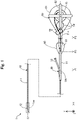
- Fig. 1 is an explanatory diagram illustrating a configuration of a drug solution injection device 1 according to the first embodiment.
- the drug solution injection device 1 is used for injecting a drug solution into a patient's body using a catheter that can be inserted into a living body lumen.
- the living body lumen includes various lumens such as a vascular system, a lymphatic gland system, a biliary system, a urinary tract system, a respiratory system, a digestive system, a secretory gland and a reproductive organ.
- the drug solution injection device 1 includes a catheter 10, an accommodation portion 50, and a wire 60.
- an axis passing through the center of the drug solution injection device 1 is represented by an axis line O (dot and dash line).
- the axis line O is consistent with an axis passing through each center of the catheter 10 and the accommodation portion 50.
- the axis line O may be inconsistent with each central axis of the catheter 10 and the accommodation portion 50.
- XYZ axes that are orthogonal to each other are illustrated.
- the X axis corresponds to a length direction of the drug solution injection device 1
- the Y axis corresponds to a width direction of the drug solution injection device 1
- the Z axis corresponds to a height direction of the drug solution injection device 1.
- the left side (-X axis direction) in Fig. 1 is referred to as a "distal end side" of the drug solution injection device 1 and each component, and the right side in Fig. 1 (+X axis direction) is referred to as a "proximal end side" of the drug solution injection device 1 and each component.
- a distal end side As for the drug solution injection device 1 and each component, an end portion positioned on the distal end side is referred to as a "distal end”, and the distal end and the vicinity thereof are referred to as a "distal end portion".
- proximal end an end portion positioned on the proximal end side
- proximal end and the vicinity thereof are referred to as a "proximal end portion”.
- the distal end side is inserted into a living body, and the proximal end side is operated by an operator such as a surgeon.
- Fig. 2 is an explanatory diagram illustrating a sectional configuration of the catheter 10.
- Fig. 2 presents a sectional configuration of a part 1pa ( Fig. 1 : dashed frame) of the catheter 10 on the distal end side.
- the XYZ axes in Fig. 2 correspond to the XYZ axes in Fig. 1 .
- the catheter 10 is inserted into a living body lumen of a patient and is used to transport a drug solution to a desired position in the patient's body to inject the drug solution into the desired position in the patient's body.
- the catheter 10 includes a hollow shaft 11, a needle portion 12, and a connector 30.
- the hollow shaft 11 is a long member extending along the axis line O.
- the hollow shaft 11 is a hollow and almost cylindrical member, in which an opening is formed on each of the distal end portion and the proximal end portion, and an inner cavity communicating between the both openings is formed thereinside.
- a coil body or a braided body may be embedded in a thick-walled portion of the hollow shaft 11 to improve at least some of flexibility, torquability, pushability, kink resistance, blood vessel followability, lesion passableness, and guidewire operability.
- the hollow shaft 11 may be composed of multiple layers made of the same or different materials.
- the needle portion 12 is a hollow needle in which an opening is formed on each of a distal end portion 12d and a proximal end portion 12p, and an inner cavity communicating between the both openings is formed thereinside ( Fig. 2 ).
- a sharp needle tip is formed on the distal end portion 12d, and the proximal end portion 12p is joined to a distal end portion 11d of the hollow shaft 11.
- the joining of the needle portion 12 can be carried out using any joining agent such as an epoxy adhesive.
- the needle portion 12 is joined to the hollow shaft 11 while the inner cavity of the needle portion 12 and the inner cavity of the hollow shaft 11 are in communication with each other.
- Both the inner cavity of the needle portion 12 and the inner cavity of the hollow shaft 11 have a substantially constant inner diameter ⁇ 1.
- the inner cavity of the needle portion 12 and the inner cavity of the hollow shaft 11 constitute a lumen 10L that contains the drug solution.
- the transverse sectional shape of the lumen 10L is almost circular.
- the connector 30 is connected to the proximal end portion of the hollow shaft 11 and is used for feeding the drug solution to the catheter 10 and inserting the wire into the catheter 10.
- the connector 30 includes a first extension portion 31, a blade portion 32, and a second extension portion 33.
- the first extension portion 31 is an almost cylindrical member connected to the proximal end portion of the hollow shaft 11 and extending along the axis line O. An inner cavity extending along the axis line O is formed inside the first extension portion 31.
- the inner cavity of the first extension portion 31 in addition to the inner cavity of the needle portion 12 and the inner cavity of the hollow shaft 11 described above, the inner cavity of the first extension portion 31 also constitutes the lumen 10L.
- a wire insertion port 31o communicating between the lumen 10L and the outside is formed on the proximal end portion of the first extension portion 31.
- the second extension portion 33 is an almost cylindrical member extending from a lateral side of the first extension portion 31 in a direction different from the first extension portion 34 on the distal end side of the first extension portion 31.
- An inner cavity in communication with the lumen 10L is formed inside the second extension portion 33.
- a drug solution feed port 33o communicating between the lumen 10L and the inner cavity of the second extension portion 33 is formed on the distal end portion of the second extension
- a position P1 of the drug solution feed port 33o is positioned on the distal end side with respect to a position P2 of the wire insertion port 31o.
- the position P1 of the drug solution feed port 33o is positioned on the distal end side with respect to a position P3 on the distal end of the wire 60 maximally wound around a wire winding portion 53 of the accommodation portion 50 described later.
- the blade portion 32 is composed of two blade-shaped members extending from the lateral side of the first extension portion 34 in the ⁇ Y axis direction on the proximal end side of the first extension portion 31. The blade portion 32 is used when the operator grasps the connector 30. At least some parts of the first extension portion 31, the blade portion 32, and the second extension portion 33, constituting the connector 30 may be integrally configured.
- the hollow shaft 11 has antithrombogenicity, flexibility, and biocompatibility, and can be made of a resin material or a metal material.
- a resin material for example, a polyamide resin, a polyolefin resin, a polyester resin, a polyurethane resin, a silicon resin, a fluororesin, or the like can be adopted.
- a metal material for example, a stainless steel such as SUS304, an NiTi alloy, a cobalt-chromium alloy, or the like can be used.
- the needle portion 12 has antithrombogenicity and biocompatibility, and can be made of a metal material of a stainless steel such as SUS304, an NiTi alloy, a cobalt-chromium alloy, or the like.
- the connector 30 can be made of a resin material, e.g. a polyurethane, a polypropylene, a hard polyvinyl chloride, or the like.
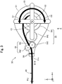
- Fig. 3 is an explanatory diagram illustrating a configuration of the accommodation portion 50.
- the accommodation portion 50 accommodates a part of the wire 60 on the proximal end side and is used to achieve advancement of the wire 60 toward the lumen 10L of the catheter 10, and retraction of the wire 60 from the lumen 10L.
- the accommodation portion 50 includes a housing 51, a handle portion 52, the wire winding portion 53, a gear 54, a wire extruding portion 55, and a valve member 56.
- the housing 51 refers to a case that accommodates the wire winding portion 53, the gear 54, the wire extruding portion 55, and the valve member 56 thereinside (inner part).
- the housing 51 is represented only by its outline as a transparent member, and each member accommodated in the housing 51 is represented by solid lines.
- the handle portion 52 refers to a handle disposed outside the housing 51 and capable of rotating in a first direction D1 and a second direction D2 represented by arrows around a rotation shaft O1.
- the rotation shaft O1 of the handle portion 52 extends inside the housing 51 and is connected to the gear 54 (first gear 541 described later). A rotative force applied to the handle portion 52 is transmitted to the gear 54 by the rotation shaft O1.
- Fig. 4 is an explanatory diagram illustrating a configuration of the wire winding portion 53, the gear 54, and the wire extruding portion 55.
- the wire winding portion 53, the gear 54, the wire extruding portion 55, and the wire 60 viewed from direction A in Fig. 3 are illustrated.
- the lower part of Fig. 4 (in the dashed frame), the rotation shaft O1, the wire winding portion 53, and the first gear 541 viewed from direction C in Fig. 4 are illustrated.
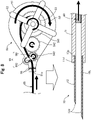
- Fig. 5 is an explanatory diagram illustrating a configuration of the valve member 56.
- the housing 51, the valve member 56, and the wire 60 viewed from direction B in Fig. 3 are illustrated.
- the XYZ axes in Fig. 4 and Fig. 5 correspond to the XYZ axes in Fig. 1 respectively.
- the gear 54 includes the first gear 541, a second gear 542, and a third gear 543.
- the first gear 541 is convex-shaped and has outer teeth 541a and inner teeth 541b.
- the third gear 543 is convex-shaped and has outer teeth 543a and inner teeth 543b.
- the first gear 541 is connected to the handle portion 52 via the rotation shaft O1.
- the second gear 542 engages with the outer teeth 541a of the first gear 541 and the outer teeth 543a of the third gear 543 such that a rotative force transmitted from the handle portion 52 to the first gear 541 is transmitted to the third gear 543.
- a reference circle diameter L11 of the outer teeth 541a of the first gear 541 is larger than a reference circle diameter L31 of the outer teeth 543a of the third gear 543 ( Fig. 4 ).
- the number of the outer teeth 541a of the first gear 541 is more than the number of the outer teeth 543a of the third gear 543.
- the reference circle diameter of the gear means an average of a circle diameter of a tooth top and a circle diameter of a tooth bottom.
- the wire winding portion 53 is an almost cylindrical member fitted into the inner teeth 541b of the first gear 541 and rotates in response to the rotation of the first gear 541 (lower part of Fig. 4 ).
- An outer diameter of the wire winding portion 53 is represented by L12 ( Fig. 4 ).
- Apart of the wire 60 on the proximal end side is previously wound around the wire winding portion 53.
- the proximal end portion of the wire 60 may or may not be fixed to the wire winding portion 53.
- the wire winding portion 53 and the first gear 541 may be integrally formed.
- the wire extruding portion 55 includes a first roller 551 and a second roller 552.
- the first roller 551 is an almost cylindrical member fitted into the inner teeth 543b of the third gear 543 and rotates in response to the rotation of the third gear 543.
- An outer diameter of the first roller 551 is represented by L32 ( Fig. 4 ).
- a lateral side of the first roller 551 is covered by a covering portion 59.
- the first roller 551 and the third gear 543 may be integrally formed.
- the second roller 552 is an almost cylindrical or almost columnar member disposed adjacent to the first roller 551 and rotates in response to the rotation of the first roller 551. Similarly to the first roller 551, a lateral side of the second roller 552 is covered by the covering portion 59.
- the wire 60 In the wire 60, a part on the proximal end side is wound around the wire winding portion 53, and a part on the distal end side passes through an opening 51o of the housing 51 and is exposed to the outside.
- the wire 60 is sandwiched between the first roller 551 and the second roller 552 at a position between the wire winding portion 53 and the opening 51o.
- the wire 60 is surrounded by the valve member 56 between the wire extruding portion 55 and the opening 51o ( Fig. 5 ).
- the valve member 56 is disposed between the wire extruding portion 55 and the opening 51o to restrict the drug solution from moving into the accommodation portion 50.
- the housing 51, the handle portion 52, the wire winding portion 53, the gear 54, and the wire extruding portion 55 can be made of a resin material, e.g. a polyurethane, a polypropylene, a hard polyvinyl chloride, or the like.
- the housing 51, the handle portion 52, the wire winding portion 53, the gear 54, and the wire extruding portion 55 may be made of the same material, or may be partially made of different materials.
- the valve member 56 and the covering portion 59 of the wire extruding portion 55 can be made of e.g. an elastic body such as a silicon rubber and an urethane rubber.
- the accommodation portion 50 allows the wire 60 to advance and retract in the lumen 10L of the catheter 10.
- the handle portion 52 of the accommodation portion 50 is rotated in the first direction D1
- the rotative force applied to the handle portion 52 is transmitted to the first gear 541 and the wire winding portion 53 through the rotation shaft O1.
- the wire winding portion 53 rotates in the first direction D1
- the wire 60 having a length corresponding to the rotation quantity of the handle portion 52 is fed toward the lumen 10L (the wire 60 advances in the lumen 10L).
- a ratio between the reference circle diameter L31 of the third gear 543 and the outer diameter L32 of the first roller 551 is lower than a ratio between the reference circle diameter L11 of the first gear 541 and the outer diameter L12 of the wire winding portion 53 (L11/L12).
- the length of the wire 60 to be extruded by the first roller 551 and the second roller 552 is longer than the length of the wire 60 to be fed by the wire winding portion 53.
- the first roller 551 and the second roller 552 push the wire 60 toward the lumen 10L while interposing some wheel slip.
- the first roller 551 and the second roller 552 can sandwich the wire 60 and push the wire 60 toward the lumen 10L by a frictional force.
- Fig. 6 is an explanatory diagram illustrating a configuration of the wire 60.
- the wire 60 includes a core shaft 61 and a covering portion 65.
- the core shaft 61 is a long member extending along the axis line O and having a substantially constant outer diameter from the distal end to the proximal end.
- the transverse sectional shape of the core shaft 61 is almost circular.
- the covering portion 65 is a coating layer applied to the surface of the core shaft 61.
- the transverse sectional shape of the wire 60 is almost circular.
- the core shaft 61 has antithrombogenicity, flexibility, and biocompatibility, and can be made of e.g.
- the wire 60 according to the first embodiment has a substantially constant outer diameter ⁇ 2 from the distal end to the proximal end.
- the outer diameter ⁇ 2 of the wire 60 is 80% or higher of the inner diameter ⁇ 1 of the lumen 10L of the catheter 10 ( Fig. 2 ).
- Fig. 7 is a diagram for explaining advancement of the wire 60 and discharge of the drug solution.
- Fig. 8 is a diagram for explaining retraction of the wire 60.
- the accommodation portion 50 is illustrated on the upper part, and a part of the catheter 10 on the distal end side is illustrated on the lower part.
- a method for using the drug solution injection device 1 will be explained with reference to Fig. 1 , Fig. 7 , and Fig. 8 .
- an operator When using the drug solution injection device 1 by means of an endoscope, an operator inserts the catheter 10 into the endoscope to move the needle portion 12 of the catheter 10 to a target position (position to which the drug solution is administered) in a patient's body. Subsequently, the operator attaches the accommodation portion 50 to the wire insertion port 31o of the catheter 10 ( Fig. 1 ). At this time, while the distal end portion of the wire 60 extruding from the opening 51o of the accommodation portion 50 is inserted into the lumen 10L of the catheter 10, the accommodation portion 50 is attached to the wire insertion port 31o. Then, the operator feeds the drug solution from the drug solution feed port 33o of the catheter 10.
- a syringe containing a drug solution is attached to the proximal end portion of the second extension portion 33, and the drug solution is fed from the syringe.
- the drug solution fed from the drug solution feed port 33o through the second extension portion 33 is charged into the lumen 10L of the catheter 10. Subsequently, the operator punctures the target position in the patient's body with the needle portion 12.
- the operator attaches the accommodation portion 50 to the catheter 10 and inserts the catheter 10 into a living body lumen of the patient while the drug solution is previously charged into the lumen 10L of the catheter 10. Then, the operator moves the needle portion 12 of the catheter 10 to the target position in the patient's body and punctures the target position with the needle portion 12.
- the operator rotates the handle portion 52 of the accommodation portion 50 in the first direction D1, as illustrated in the upper part of Fig. 7 .
- the first gear 541 and the wire winding portion 53 rotate in the first direction D1
- the wire 60 is fed into the lumen 10L of the catheter 10 (i.e. the wire 60 advances).
- the drug solution DS charged in the lumen 10L of the catheter 10 is extruded by the advanced wire 60, and the drug solution DS in an amount corresponding to a volume of the advanced wire 60 is discharged from the distal end of the needle portion 12.
- the drug solution DS in an amount corresponding to the rotation quantity of the handle portion 52 is discharged from the distal end of the needle portion 12.
- the second gear 542 rotates in a direction opposite to the first direction D1
- the third gear 543 and the first roller 551 rotate in the first direction D1
- the second roller 552 rotates in a direction opposite to the first direction D1.
- the wire 60 is extruded into the lumen 10L of the catheter 10.
- the operator rotates the handle portion 52 of the accommodation portion 50 in the second direction D2, as illustrated in the upper part of Fig. 8 .
- the first gear 541 and the wire winding portion 53 rotate in the second direction D2
- the wire 60 is wound from the lumen 10L of the catheter 10 (i.e. the wire 60 retracts).
- the second gear 542 rotates in a direction opposite to the second direction D2
- the third gear 543 and the first roller 551 rotate in the second direction D2
- the second roller 552 rotates in a direction opposite to the second direction D2.
- a case that the drug solution DS in a larger amount than a capacity of the lumen 10L of the catheter 10 is administered to a patient is assumed.
- the operator continues to rotate the handle portion 52 in the second direction D2 to maximally wind the wire 60 ( Fig. 1 ).
- the operator recharges the drug solution DS into the lumen 10L of the catheter 10 from the drug solution feed port 33o, and then only needs to repeat the operations explained in Fig. 7 and Fig. 8 .
- the wire 60 that is inserted into the lumen 10L containing the drug solution DS and is advanced from the proximal end of the lumen 10L toward the distal end side (in the -X direction) so as to discharge the drug solution DS in the lumen 10L from the distal end of the needle portion 12, is included. That means, in the drug solution injection device 1 according to the first embodiment, the drug solution DS in the lumen 10L is extruded by the wire 60 so as to be discharged from the distal end of the needle portion 12 ( Fig. 7 ).
- an amount of the drug solution DS to be discharged can be the same as a volume of the wire 60, and therefore the injection dose of the drug solution DS can be precisely controlled.
- the drug solution DS in the lumen 10L can be thoroughly used by extruding the drug solution DS in the lumen 10L by the wire 60.
- waste of the drug solution DS can be reduced.
- the outer diameter ⁇ 2 of the wire 60 is substantially constant from the distal end to the proximal end ( Fig. 6 ).
- the amount of the drug solution DS to be discharged from the distal end of the needle portion 12 can be easily comprehended depending on the length of the wire 60 advanced in the lumen 10L.
- the drug solution injection device 1 includes the accommodation portion 50 connected to the proximal end portion of the catheter 10, accommodating a part of the wire 60 on the proximal end side, and allowing the wire 60 to advance and retract in the lumen 10L ( Fig. 1 , Fig. 5 ).
- the accommodation portion 50 feeds the wire 60 to the lumen 10L to advance the wire 60, and winds the wire 60 from the lumen 10L to retract the wire 60.
- the wire 60 can be reliably advanced and retracted.
- the accommodation portion 50 can be downsized.
- the accommodation portion 50 includes the handle portion 52 connected to the wire winding portion 53, and the wire winding portion 53 feeds and winds the wire 60 in a length corresponding to the rotation quantity of the handle portion 52 ( Fig. 3 ). Thereby, the operator can easily feed and wind the wire 60 by rotating the handle portion 52.
- the accommodation portion 50 allows the drug solution DS in an amount corresponding to the rotation quantity of the handle portion 52 to be discharged from the distal end of the needle portion 12 ( Fig. 7 ).
- the amount of the drug solution DS to be discharged from the distal end of the needle portion 12 can be easily controlled depending on the rotation quantity of the handle portion 52.
- the injection dose of the drug solution DS can be precisely controlled and waste of the drug solution DS can be reduced.
- the accommodation portion 50 includes the wire extruding portion 55 (first roller 551, second roller 552) that extrudes the wire 60 fed from the wire winding portion 53, toward the lumen 10L ( Fig. 3 ).
- the wire 60 can be reliably pushed and advanced into the lumen 10L.
- the length of the wire 60 to be extruded by the wire extruding portion 55 is longer than the length of the wire 60 to be fed by the wire winding portion 53 ( Fig. 3 , Fig. 4 ).
- the wire 60 can be reliably pushed and advanced into the lumen 10L.
- the accommodation portion 50 includes the valve member 56 that restricts the drug solution DS in the lumen 10L from moving into the accommodation portion 50.
- the valve member 56 that restricts the drug solution DS in the lumen 10L from moving into the accommodation portion 50.
- each transverse sectional shape of the lumen 10L of the catheter 10 and the wire 60 is almost circular, and the outer diameter ⁇ 2 of the wire 60 is 80% or larger of the inner diameter ⁇ 1 of the lumen 10L ( Fig. 2 , Fig. 5 , Fig. 6 ).
- the drug solution DS in the lumen 10L can be extruded by the wire 60 while maintaining slidability of the wire 60 in the lumen 10L.
- the wire 60 according to the first embodiment includes the covering portion 65, the drug solution DS can be prevented from remaining on the surface of the wire 60.
- the catheter 10 further includes the connector 30 ( Fig. 1 ).
- the connector 30 is configured such that the drug solution feed port 33o is disposed on the distal end side with respect to the wire insertion port 31o ( Fig. 1 : Positions P1 and P2).
- the drug solution DS can be fed from the drug solution feed port 33o without inhibition of the feed due to the wire 60, while the distal end portion of the wire 60 is inserted into the wire insertion port 31o.
- the drug solution feed port 33o of the connector 30 is disposed on the distal end side with respect to the distal end of the wire 60 maximally wound around the wire winding portion 53 ( Fig. 1 : positions P1 and P3).
- the drug solution DS can be fed from the drug solution feed port 33o without inhibition of the feed due to the wire 60 when the wire 60 is maximally wound around the accommodation portion 50 by rotating the handle portion 52.
- the connector 30 is configured such that the wire insertion port 31o is formed on the proximal end portion of the first extension portion 31, and the drug solution feed port 33o is formed on the distal end portion of the second extension portion 33 extending in a direction different from the first extension portion 31 ( Fig. 1 ).
- the accommodation portion 50 and the syringe can be attached to the connector while the accommodation portion 50 attached to the wire insertion port 31o and the syringe attached to the drug solution feed port 33o do not interfere with each other (do not disturb each other). That means, in the drug solution injection device 1 according to the first embodiment, insertion of the wire 60 into the wire insertion port 31o and feed of the drug solution DS from the drug solution feed port 33o can be smoothly carried out.
- FIG. 9 is an explanatory diagram illustrating a configuration of an accommodation portion 50A according to the second embodiment.
- a drug solution injection device 1A according to the second embodiment includes the accommodation portion 50A in place of the accommodation portion 50 explained in the first embodiment.
- the accommodation portion 50A does not include the wire extruding portion 55 (first roller 551 and second roller 552), the second gear 542, and the third gear 543 that have been explained in the first embodiment.
- the configuration of the accommodation portion 50A can be variously changed, and the wire extruding portion 55 and the second and third gears 542 and 543 for transmitting the rotative force to the wire extruding portion 55 may be omitted.
- the wire winding portion 53 can advance the wire 60 by feeding the wire 60 into the lumen 10L and retract the wire 60 by winding the wire 60 from the lumen 10L. That means, the same effect as in the first embodiment can also be exhibited by the drug solution injection device 1A using the accommodation portion 50A according to the second embodiment.
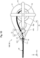
- FIG. 10 is an explanatory diagram illustrating a configuration of an accommodation portion 50B according to the third embodiment.
- a drug solution injection device 1B according to the third embodiment includes the accommodation portion 50B in place of the accommodation portion 50 explained in the first embodiment.
- the accommodation portion 50B further include a third roller 571 and a fourth roller 572 in addition to the configuration explained in the first embodiment.
- Both the third roller 571 and the fourth roller 572 are almost cylindrical or almost columnar members.
- both the lateral sides of the third roller 571 and the fourth roller 572 are covered by the covering portion 59.
- the third roller 571 and the fourth roller 572 are disposed between the wire extruding portion 55 and the valve member 56 (opening 51o) to sandwich the wire 60 on the distal end side with respect to the wire extruding portion 55.
- the third roller 571 and the fourth roller 572 rotate in response to the rotation of the wire extruding portion 55.
- the configuration of the accommodation portion 50B can be variously modified, and may further include configurations not explained in the first embodiment e.g. like the third roller 571 and the fourth roller 572.
- the same effect as in the first embodiment can also be exhibited by the drug solution injection device 1B using the accommodation portion 50B according to the third embodiment.
- the wire 60 can be extruded toward the lumen 10L with a stronger force by the third roller 571 and the fourth roller 572.
- FIG. 11 is an explanatory diagram illustrating a configuration of an accommodation portion 50C according to the fourth embodiment.
- a drug solution injection device 1C according to the fourth embodiment includes the accommodation portion 50C in place of the accommodation portion 50 explained in the first embodiment.
- the accommodation portion 50C includes a handle portion 52C in place of the handle portion 52 and does not include the valve member 56 explained in the first embodiment.
- the handle of the handle portion 52C has a shape different from that in the first embodiment.
- the configuration of the accommodation portion 50C can be variously changed, and a shape of at least a part of a constituent, e.g. the handle portion 52C, as well as the housing 51, the gear 54, and the wire extruding portion 55, may be changed.
- a part of the configuration explained in the first embodiment may be omitted.
- the same effect as in the first embodiment can also be exhibited by the drug solution injection device 1C using the accommodation portion 50C according to the fourth embodiment.
- Fig. 12 is an explanatory diagram illustrating a configuration of a wire 60D according to the fifth embodiment.
- a drug solution injection device 1D according to the fifth embodiment includes the wire 60D in place of the wire 60 explained in the first embodiment.
- the wire 60D includes a core shaft 61D, a coil body 62, a distal joint part 63, a proximal joint part 64, and a covering portion 65D.
- the core shaft 61D includes a first small-diameter portion 611, a first tapered portion 612, a second small-diameter portion 613, a second tapered portion 614, and a large-diameter portion 615.
- the first small-diameter portion 611 refers to a part where an outer diameter of the core shaft 61D is smallest, and is disposed on the distal end of the core shaft 61D.
- the first tapered portion 612 refers to a part having an outer diameter gradually increasing from the distal end side to the proximal end side, and is disposed between the first small-diameter portion 611 and the second small-diameter portion 613.
- the second small-diameter portion 613 refers to a part having a slightly larger diameter than of the first small-diameter portion 611, and is disposed between the first tapered portion 612 and the second tapered portion 614.
- the second tapered portion 614 refers to a part having an outer diameter gradually increasing from the distal end side to the proximal end side, and is disposed between the second small-diameter portion 613 and the large-diameter portion 615.
- the large-diameter portion 615 refers to a part where an outer diameter of the core shaft 61D is largest, and is disposed on the proximal end side of the core shaft 61D.
- the coil body 62 is formed by spirally winding a wire around the small-diameter portion (specifically, the first small-diameter portion 611, the first tapered portion 612, and the second small-diameter portion 613) of the core shaft 61D.
- the coil body 62 may be a single-thread coil formed by winding one wire in a single-thread form, a multi-thread coil formed by winding a plurality of wires in a multi-thread form, a single-thread strand coil formed by winding a strand obtained by twisting a plurality of wires together in a single-thread form, or a multi-thread strand coil formed by using a plurality of strands obtained by twisting a plurality of wires together and winding each strand in a multi-thread form.
- the distal joint part 63 is disposed on the distal end portion of the wire 60D and integrally holds the distal end portion of the first small-diameter portion 611 and the distal end portion of the coil body 62.
- the proximal joint part 64 integrally holds the proximal end portion of the second small-diameter portion 613 and the proximal end portion of the coil body 62.
- the covering portion 65D is a resin layer that covers the outsides of the core shaft 61D, the coil body 62, the distal joint part 63, and the proximal joint part 64.
- the covering portion 65D covers the respective parts so as to have such a thickness that the outer diameter of the wire 60D is an outer diameter ⁇ 21 substantially constant from the distal end to the proximal end.
- the core shaft 61D can be made of the same material as for the core shaft 61 in the first embodiment.
- the coil body 62 can be made of a stainless alloy such as SUS304 and SUS316, a superelastic alloy such as an NiTi alloy, a piano wire, a radiolucent alloy such as a nickel-chromium alloy and a cobalt alloy, a radiopaque alloy such as gold, platinum, tungsten, and an alloy containing any of these elements (e.g. a platinum-nickel alloy), or another known material.
- the distal joint part 63 and the proximal joint part 64 can be made of any joining agent, e.g. a metal solder such as silver solder, gold solder, zinc, Sn-Ag alloy, and Au-Sn alloy, or an adhesive such as an epoxy adhesive.
- the covering portion 65D can be made of the same material as for the covering portion 65 in the first embodiment.
- the configuration of the wire 60D can be variously changed, and may be configured such that a small-diameter portion (e.g. the first small-diameter portion 611, the first tapered portion 612, and the second small-diameter portion 613) is formed on the distal end side of the core shaft 61D, and the small-diameter portion is covered with the coil body 62.
- a small-diameter portion e.g. the first small-diameter portion 611, the first tapered portion 612, and the second small-diameter portion 613
- the same effect as in the first embodiment can also be exhibited by the drug solution injection device 1D using the wire 60D according to the fifth embodiment.
- use of the wire 60D according to the fifth embodiment can flexibilize the distal end portion of the wire 60D, the safety of the drug solution injection device 1D can be improved.
- Fig. 13 is an explanatory diagram illustrating a configuration of a wire 60E according to the sixth embodiment.
- a drug solution injection device 1E according to the sixth embodiment includes the wire 60E in place of the wire 60 explained in the first embodiment.
- the wire 60E includes a core shaft 66 and a plurality of thick-walled portions 671 to 673.
- the core shaft 66 is a long and solid member extending along the axis line O.
- Each of the thick-walled portions 671 to 673 is a member having an outer diameter larger than the outer diameter of the core shaft 66, and covers a part of the surface of the core shaft 66.
- Each of the thick-walled portions 671 to 673 has an almost circular transverse section, and has a substantially identical outer diameter ⁇ 22.
- the thick-walled portions 671 to 673 are joined to the core shaft 66 at a distance from each other.
- any joining agent such as an epoxy adhesive can be used.
- any number of thick-walled portions 671 to 673 may be formed on the wire 60E.
- a length in the axis line O direction and a shape of the thick-walled portions 671 to 673 can be arbitrarily determined.
- the distance between the adjacent thick-walled portions (in other words, the length between the separated thick-walled portions 671 to 673) can also be arbitrarily determined.
- the thick-walled portions 671 to 673 may be composed of a coil body formed by spirally winding a wire around the core shaft 66, and a resin body for covering the surface of the coil body.
- the configuration of the wire 60E can be variously modified, and the wire 60E may be configured so as to include a plurality of thick-walled portions 671 to 673.
- the same effect as in the first embodiment can also be exhibited by the drug solution injection device 1E using this wire 60E according to the sixth embodiment.
- use of the wire 60E according to the sixth embodiment facilitates comprehension of an amount of the drug solution DS to be discharged from the needle portion 12 in association with the advancement of the one thick-walled portion 671 toward the lumen 10L.
- use of the wire 60E according to the sixth embodiment facilitates control of the amount of the drug solution DS to be discharged from the needle portion 12 depending on the number of the thick-walled portions 671 to 673 to be advanced toward the lumen 10L.
- Fig. 14 is an explanatory diagram illustrating a configuration of a drug solution injection device 1F according to the seventh embodiment.
- the drug solution injection device 1F according to the seventh embodiment does not include the accommodation portion 50 explained in the first embodiment.
- an operator grasps the wire 60 inserted from the wire insertion port 31o of the connector 30 by a hand (or using a grasping tool such as forceps) to advance and retract the wire 60.
- the configuration of the drug solution injection device 1F can be variously modified, and, for example, at least a part of the configuration explained in the first embodiment, such as the accommodation portion 50 may be omitted.
- This drug solution injection device 1F according to the seventh embodiment also makes it possible to discharge the drug solution DS in an amount corresponding to the length of the advanced wire 60 from the distal end of the needle portion 12. Thereby, the drug solution injection device 1F according to the seventh embodiment makes it possible to precisely control the injection dose of the drug solution DS, and reduce waste of the drug solution DS.
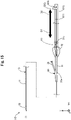
- Fig. 15 is an explanatory diagram illustrating a configuration of a drug solution injection device 1G according to the eighth embodiment.
- the drug solution injection device 1G according to the eighth embodiment includes an accommodation portion 50G in place of the accommodation portion 50 explained in the first embodiment.
- the accommodation portion 50G includes a housing 51G and a handle portion 52G.
- the housing 51G is an almost rectangular case extending in the direction of the axis line O.
- a linear groove 511 that communicates between the inside and the outside of the housing 51G is formed on one side of the housing 51G.
- the handle portion 52G is arranged such that one end is positioned outside the housing 51G and the other end is positioned inside the housing 51G.
- the other end of the handle portion 52G grasps the proximal end portion of the wire 60.
- This accommodation portion 50G allows the operator to slide the handle portion 52G toward the distal end side (in other words, in the first direction D1) to advance the wire 60 into the lumen 10L.
- the operator can slide the handle portion 52G toward the proximal end side (in other words, in the second direction D2) to retract the wire 60 from the inside of the lumen 10L.
- this drug solution injection device 1G includes the accommodation portion 50G connected to the proximal end portion of the catheter 10, accommodating a part of the wire 60 on the proximal end side, and allowing the wire 60 to advance and retract in the lumen 10L ( Fig. 15 ). Thereby, the wire 60 can be advanced and retracted without direct contact between an operator and the wire 60.
- the accommodation portion 50G makes it possible to discharge the drug solution DS in an amount corresponding to the length of the advanced wire 60 from the distal end of the needle portion 12. Thereby, the injection dose of the drug solution DS can be precisely controlled and waste of the drug solution DS can be reduced.
- the configuration of the drug solution injection device can be variously modified.
- the drug solution injection device need not include any accommodation portion.
- the drug solution injection device may include other constituents not explained in the above embodiments.
- a syringe for injecting the drug solution for example, a controller for controlling each part of the drug solution injection device, or the like can be used.
- the catheter may be configured as a multi-lumen catheter including another lumen different from the lumen for the drug solution.
- a valve member for restricting reverse flow of the drug solution may be disposed in the lumen of the catheter.
- the catheter may include a mesh member for positioning the needle portion in a living body lumen.
- the catheter may include a balloon member for intercepting current of body fluids (e.g. blood) flowing through the living body lumen and positioning the needle portion.
- the drug solution feed port and wire insertion port of the connector may be disposed at the almost same position.
- the drug solution feed port of the connector may be disposed on the proximal end side with respect to the wire insertion port.
- the drug solution feed port of the connector and the distal end of the wire maximally wound around the accommodation portion may be positioned at the almost same position.
- the drug solution feed port of the connector may be disposed on the proximal end side with respect to the distal end of the wire maximally wound around the accommodation portion.
- the connector need not include the second extension portion having the drug solution feed port.
- the operator may operate the wire by attaching the syringe to the wire insertion port, then charging the drug solution into the syringe, then detaching the syringe, and attaching the accommodation portion to the same wire insertion port.
- the accommodation portion may include an electric handle portion that is driven by an electric motor or the like in place of a manually-rotatable handle portion.
- the accommodation portion may further include an input portion for inputting a feed amount of the drug solution (or a rotation quantity of the electric handle portion).
- the input portion can be achieved in any form such as a touch panel or operation buttons.
- the accommodation portion may include a fixation member for fixing the accommodation portion to the wire insertion port of the connector.
- the reference circle diameter L11 of the first gear, the reference circle diameter L31 of the third gear, the outer diameter L12 of the wire winding portion, and the outer diameter L32 of the first roller can be arbitrarily determined.
- the ratio between the reference circle diameter L31 of the third gear and the outer diameter L32 of the first roller (L31/L32) is not necessarily smaller than the ratio between the reference circle diameter L11 of the first gear and the outer diameter L12 of the wire winding portion (L11/L12).
- the first gear and the third gear need not have the inner teeth and outer teeth.
- the first gear and the wire winding portion may be joined to each other by any joining agent such as an epoxy adhesive.
- the third gear and the first roller may be joined to each other by any joining agent such as an epoxy adhesive.
- the rotative force of the handle portion may be transmitted to the wire winding portion and the wire extruding portion by using a means other than the gears.
- a means other than the gears for example, a pulley and a belt, a magnetic force, or the like can be used.
- the configuration of the wire can be variously modified.
- the outer diameter of the wire is not necessarily substantially constant from the distal end to the proximal end.
- the wire may be configured such that a part on the distal end side is formed so as to have a relatively narrow diameter, and a part on the proximal end side is formed so as to have a relatively thick diameter.
- the outer diameter of the wire may be less than 80% of the inner diameter of the lumen.
- the transverse sectional shape of the wire is not necessarily almost circular.
- the configurations of the drug solution injection devices according to the first to eighth embodiments and the configurations of the drug solution injection device, the catheter, the accommodation portion, and the wire according to Modification Examples 1 to 4 may be combined as appropriate.
- the wire explained in any of the fifth and sixth embodiments may be used in the drug solution injection device explained in the first, seventh, and eighth embodiments.
- the accommodation portion explained in any of the second, third, and fourth embodiments may be used in the drug solution injection device having the configuration explained in the first embodiment.
Landscapes
- Health & Medical Sciences (AREA)
- Life Sciences & Earth Sciences (AREA)
- Heart & Thoracic Surgery (AREA)
- Hematology (AREA)
- Engineering & Computer Science (AREA)
- Anesthesiology (AREA)
- Biomedical Technology (AREA)
- Animal Behavior & Ethology (AREA)
- General Health & Medical Sciences (AREA)
- Public Health (AREA)
- Veterinary Medicine (AREA)
- Vascular Medicine (AREA)
- Pulmonology (AREA)
- Biophysics (AREA)
- Infusion, Injection, And Reservoir Apparatuses (AREA)
- Media Introduction/Drainage Providing Device (AREA)
Abstract
Description
- The disclosed embodiments relate to a drug solution injection device.
- There are known devices for injecting a drug solution into a patient's body using a catheter that can be inserted into a living body lumen. For example,
Patent Document 1 discloses an injection device including an injection catheter and a hand pump connected to a proximal end of the injection catheter. For example, Patent Document 2 discloses a drug solution injection device including an extension tube and a syringe connected to a proximal end of the extension tube, where an RFID (Radio Frequency Identification) chip storing various recorded data is attached to the syringe. -
- Patent Literature 1:
JP 2001-519212 W - Patent Literature 2:
WO2005/084732 - There are various doses for drug solutions that are injected into a patient's body. In this regard, the technologies described in
Patent Literature 1 and Patent Literature 2 have had a problem that it is impossible to respond to a request for injecting a trace amount of the drug solution into a patient's body because an injection dose of the drug solution cannot be precisely controlled. Also, the technologies described inPatent Literature 1 and Patent Literature 2 have had a problem that the drug solution is wasted because the drug solution remains in the injection catheter and the extension tube after use. Furthermore, the technology described in Patent Literature 2 has had a problem that the drug solution injection device is large and cannot be not easily installed and set up. - The disclosed embodiments were made to solve at least a part of the aforementioned problems, and an object of the disclosed embodiments is to provide a drug solution injection device capable of precisely controlling an injection dose of a drug solution and reducing waste of the drug solution.
- The disclosed embodiments were made to solve at least a part of the aforementioned problems, and can be achieved as the following aspects.
- (1) According to one aspect of the disclosed embodiments, a drug solution injection device is provided. This drug solution injection device includes: a catheter that has a hollow shaft, a hollow needle portion disposed on a distal end of the hollow shaft, and a lumen formed inside each of the hollow shaft and the needle portion and containing a drug solution; and a wire that is inserted into the lumen and is advanced from a proximal end of the lumen toward a distal end side so as to discharge the drug solution in the lumen from a distal end of the needle portion.
According to this configuration, the drug solution injection device includes a wire to be inserted into a lumen for containing a drug solution and advanced from a proximal end of the lumen toward a distal end side so as to discharge the drug solution in the lumen from a distal end of the needle portion. That means, in this configuration, the drug solution in the lumen is extruded by the wire so as to be discharged from the distal end of the needle portion. Thereby, an amount of the drug solution to be discharged can be the same as a volume of the wire, and therefore the injection dose of the drug solution can be precisely controlled. In this configuration, the drug solution in the lumen can be thoroughly used by extruding the drug solution from the lumen by the wire. Thus, waste of the drug solution can be reduced. - (2) In the drug solution injection device according to the aforementioned aspect, an outer diameter of the wire may be substantially constant from the distal end to the proximal end.
According to this configuration, since the outer diameter of the wire is substantially constant from the distal end to the proximal end, an amount of the drug solution to be discharged from the distal end of the needle portion can be easily comprehended depending on the length of the wire advanced in the lumen. - (3) The drug solution injection device according to the aforementioned aspect may further include an accommodation portion that is connected to the proximal end portion of the catheter, accommodates a part of the wire on the proximal end side, and allows the wire to advance and retract in the lumen.
According to this configuration, the drug solution injection device includes an accommodation portion connected to the proximal end portion of the catheter, accommodating a part of the wire on the proximal end side, and allowing the wire to advance and retract in the lumen. Thereby, the wire can be advanced and retracted without direct contact between an operator and the wire. - (4) In the drug solution injection device according to the aforementioned aspect, the accommodation portion may advance the wire in the lumen, so that the drug solution in an amount corresponding to a length of the advanced wire is discharged from the distal end of the needle portion.
According to this configuration, the accommodation portion allows the drug solution in an amount corresponding to the length of the advanced wire to be discharged from the distal end of the needle portion. Thereby, the injection dose of the drug solution can be precisely controlled and waste of the drug solution can be reduced. - (5) In the drug solution injection device according to the aforementioned aspect, the accommodation portion may feed the wire toward the lumen to advance the wire, and wind the wire from the lumen to retract the wire.
According to this configuration, since the accommodation portion feeds the wire to the lumen to advance the wire and winds the wire from the lumen to retract the wire, the wire can be reliably advanced and retracted. In addition, since the wire is wound for accommodation, the accommodation portion can be downsized. - (6) In the drug solution injection device according to the aforementioned aspect, the accommodation portion includes a wire winding portion around which a part of the wire on the proximal end side is wound, and a handle portion connected to the wire winding portion. The wire winding portion may feed and wind the wire in a length corresponding to a rotation quantity of the handle portion.
According to this configuration, the accommodation portion includes the handle portion connected to the wire winding portion, and the wire winding portion feeds and winds the wire in a length corresponding to a rotation quantity of the handle portion. Thereby, an operator can easily feed and wind the wire by rotating the handle portion. - (7) In the drug solution injection device according to the aforementioned aspect, the accommodation portion further includes a wire extruding portion that extrudes the wire fed from the wire winding portion, toward the lumen. The wire extruding portion includes first and second rollers that rotate in response to the rotation of the handle portion, and may extrude the wire while the wire is sandwiched between the first and second rollers.
According to this configuration, since the accommodation portion includes the wire extruding portion that extrudes the wire fed from the wire winding portion toward the lumen, the wire can be reliably pushed and advanced into the lumen. - (8) In the drug solution injection device according to the aforementioned aspect, in response to the same rotation quantity of the handle portion, the length of the wire to be extruded by the wire extruding portion may be longer than the length of the wire to be fed by the wire winding portion.
According to this configuration, in response to the same rotation quantity of the handle portion, the length of the wire to be extruded by the wire extruding portion is longer than the length of the wire to be fed by the wire winding portion, and therefore the wire can be reliably pushed and advanced into the lumen. - (9) In the drug solution injection device according to the aforementioned aspect, the accommodation portion may further include a valve member that is disposed between the wire extruding portion and the proximal end portion of the catheter to restrict the drug solution in the lumen from moving into the accommodation portion.
According to this configuration, the accommodation portion includes the valve member for restricting the drug solution in the lumen from moving into the accommodation portion. Thereby, the drug solution in the lumen can be prevented from entering the accommodation portion, and the inside of the accommodation portion can be maintained in an airtight state. - (10) In the drug solution injection device according to the aforementioned aspect, the accommodation portion may allow the drug solution in an amount corresponding to the rotation quantity of the handle portion to be discharged from the distal end of the needle portion.
According to this configuration, the accommodation portion allows the drug solution in an amount corresponding to the rotation quantity of the handle portion to be discharged from the distal end of the needle portion. Thereby, the amount of the drug solution to be discharged from the distal end of the needle portion can be easily controlled depending on the rotation quantity of the handle portion. As a result, the injection dose of the drug solution can be precisely controlled and waste of the drug solution can be reduced. - (11) In the drug solution injection device according to the aforementioned aspect, the catheter further includes a connector having a drug solution feed port for feeding the drug solution to the lumen and a wire insertion port for inserting the wire into the lumen, connected to the proximal end portion of the hollow shaft, and in communication with the lumen. The drug solution feed port may be disposed on the distal end side with respect to the wire insertion port.
According to this configuration, since the catheter further includes a connector, convenience of inserting the wire into the catheter can be improved. The connector is configured such that the drug solution feed port is disposed on the distal end side with respect to the wire insertion port. Thus, the drug solution can be fed from the drug solution feed port without inhibition of the feed due to the wire, while the distal end portion of the wire is inserted into the wire insertion port. - (12) In the drug solution injection device according to the aforementioned aspect, the catheter further includes the connector having the drug solution feed port for feeding the drug solution to the lumen and the wire insertion port for inserting the wire into the lumen, connected to the proximal end portion of the hollow shaft, and in communication with the lumen. The drug solution feed port may be disposed on the distal end side with respect to the distal end of the wire maximally wound around the wire winding portion by the rotation of the handle portion.
According to this configuration, the drug solution feed port of the connector is disposed on the distal end side with respect to the distal end of the wire maximally wound around the wire winding portion. Thus, the drug solution can be fed from the drug solution feed port without inhibition of the feed due to the wire when the wire is maximally wound around the accommodation portion by rotating the handle portion. - (13) In the drug solution injection device according to the aforementioned aspect, the connector further includes a first extension portion extending in a longitudinal direction of the catheter and a second extension portion extending from a lateral side of the first extension portion on the distal end side of the first extension portion. The drug solution feed port may be formed on a distal end portion of the second extension portion, and the wire insertion port may be formed on a proximal end portion of the first extension portion.
According to this configuration, the connector is configured such that the wire insertion port is formed on the proximal end portion of the first extension portion, and the drug solution feed port is formed on the distal end portion of the second extension portion extending from the lateral side of the first extension portion on the distal end side of the first extension portion. Thereby, insertion of the wire into the wire insertion port and feed of the drug solution from the drug solution feed port can be smoothly carried out. - (14) In the drug solution injection device according to the aforementioned aspect, each transverse sectional shape of the lumen and the wire is almost circular, and the outer diameter of the wire may be 80% or larger of an inner diameter of the lumen.
According to this configuration, each transverse sectional shape of the lumen and the wire is almost circular, and the outer diameter of the wire is 80% or larger of the inner diameter of the lumen. Thereby, the drug solution in the lumen can be extruded by the wire while maintaining slidability of the wire in the lumen. - The disclosed embodiments can be achieved in various aspects e.g. in a configuration of a drug solution injection device, a catheter and wire for injecting the drug solution, a wire and accommodation portion for injecting the drug solution, a system including a drug solution injection device, a system including a wire and accommodation portion, a method for manufacturing these devices and systems, and the like.
-
-
Fig. 1 is an explanatory diagram illustrating a configuration of a drug solution injection device according to the first embodiment. -
Fig. 2 is an explanatory diagram illustrating a sectional configuration of a catheter. -
Fig. 3 is an explanatory diagram illustrating a configuration of an accommodation portion. -
Fig. 4 is an explanatory diagram illustrating a configuration of a wire winding portion, a gear, and a wire extruding portion. -
Fig. 5 is an explanatory diagram illustrating a configuration of a valve member. -
Fig. 6 is an explanatory diagram illustrating a configuration of a wire. -
Fig. 7 is a diagram for explaining advancement of the wire and discharge of a drug solution. -
Fig. 8 is a diagram for explaining retraction of the wire. -
Fig. 9 is an explanatory diagram illustrating a configuration of an accommodation portion according to the second embodiment. -
Fig. 10 is an explanatory diagram illustrating a configuration of an accommodation portion according to the third embodiment. -
Fig. 11 is an explanatory diagram illustrating a configuration of an accommodation portion according to the fourth embodiment. -
Fig. 12 is an explanatory diagram illustrating a configuration of a wire according to the fifth embodiment. -
Fig. 13 is an explanatory diagram illustrating a configuration of a wire according to the sixth embodiment. -
Fig. 14 is an explanatory diagram illustrating a configuration of a drug solution injection device according to the seventh embodiment. -
Fig. 15 is an explanatory diagram illustrating a configuration of a drug solution injection device according to the eighth embodiment. -
Fig. 1 is an explanatory diagram illustrating a configuration of a drugsolution injection device 1 according to the first embodiment. The drugsolution injection device 1 is used for injecting a drug solution into a patient's body using a catheter that can be inserted into a living body lumen. Herein, the living body lumen includes various lumens such as a vascular system, a lymphatic gland system, a biliary system, a urinary tract system, a respiratory system, a digestive system, a secretory gland and a reproductive organ. The drugsolution injection device 1 includes acatheter 10, anaccommodation portion 50, and awire 60. - In
Fig. 1 , an axis passing through the center of the drugsolution injection device 1 is represented by an axis line O (dot and dash line). In the example ofFig. 1 , the axis line O is consistent with an axis passing through each center of thecatheter 10 and theaccommodation portion 50. However, the axis line O may be inconsistent with each central axis of thecatheter 10 and theaccommodation portion 50. InFig. 1 , XYZ axes that are orthogonal to each other are illustrated. The X axis corresponds to a length direction of the drugsolution injection device 1, the Y axis corresponds to a width direction of the drugsolution injection device 1, and the Z axis corresponds to a height direction of the drugsolution injection device 1. The left side (-X axis direction) inFig. 1 is referred to as a "distal end side" of the drugsolution injection device 1 and each component, and the right side inFig. 1 (+X axis direction) is referred to as a "proximal end side" of the drugsolution injection device 1 and each component. As for the drugsolution injection device 1 and each component, an end portion positioned on the distal end side is referred to as a "distal end", and the distal end and the vicinity thereof are referred to as a "distal end portion". In addition, an end portion positioned on the proximal end side is referred to as a "proximal end", and the proximal end and the vicinity thereof are referred to as a "proximal end portion". The distal end side is inserted into a living body, and the proximal end side is operated by an operator such as a surgeon. These definitions are common for the figures followingFig. 1 . -
Fig. 2 is an explanatory diagram illustrating a sectional configuration of thecatheter 10.Fig. 2 presents a sectional configuration of a part 1pa (Fig. 1 : dashed frame) of thecatheter 10 on the distal end side. The XYZ axes inFig. 2 correspond to the XYZ axes inFig. 1 . Thecatheter 10 is inserted into a living body lumen of a patient and is used to transport a drug solution to a desired position in the patient's body to inject the drug solution into the desired position in the patient's body. Thecatheter 10 includes ahollow shaft 11, aneedle portion 12, and aconnector 30. - The
hollow shaft 11 is a long member extending along the axis line O. Thehollow shaft 11 is a hollow and almost cylindrical member, in which an opening is formed on each of the distal end portion and the proximal end portion, and an inner cavity communicating between the both openings is formed thereinside. A coil body or a braided body may be embedded in a thick-walled portion of thehollow shaft 11 to improve at least some of flexibility, torquability, pushability, kink resistance, blood vessel followability, lesion passableness, and guidewire operability. Thehollow shaft 11 may be composed of multiple layers made of the same or different materials. - The
needle portion 12 is a hollow needle in which an opening is formed on each of adistal end portion 12d and aproximal end portion 12p, and an inner cavity communicating between the both openings is formed thereinside (Fig. 2 ). In theneedle portion 12, a sharp needle tip is formed on thedistal end portion 12d, and theproximal end portion 12p is joined to adistal end portion 11d of thehollow shaft 11. The joining of theneedle portion 12 can be carried out using any joining agent such as an epoxy adhesive. Herein, theneedle portion 12 is joined to thehollow shaft 11 while the inner cavity of theneedle portion 12 and the inner cavity of thehollow shaft 11 are in communication with each other. Both the inner cavity of theneedle portion 12 and the inner cavity of thehollow shaft 11 have a substantially constant inner diameter Φ1. The inner cavity of theneedle portion 12 and the inner cavity of thehollow shaft 11 constitute alumen 10L that contains the drug solution. The transverse sectional shape of thelumen 10L is almost circular. - The
connector 30 is connected to the proximal end portion of thehollow shaft 11 and is used for feeding the drug solution to thecatheter 10 and inserting the wire into thecatheter 10. Theconnector 30 includes afirst extension portion 31, ablade portion 32, and asecond extension portion 33. - The
first extension portion 31 is an almost cylindrical member connected to the proximal end portion of thehollow shaft 11 and extending along the axis line O. An inner cavity extending along the axis line O is formed inside thefirst extension portion 31. In the example ofFig. 1 , in addition to the inner cavity of theneedle portion 12 and the inner cavity of thehollow shaft 11 described above, the inner cavity of thefirst extension portion 31 also constitutes thelumen 10L. A wire insertion port 31o communicating between thelumen 10L and the outside is formed on the proximal end portion of thefirst extension portion 31. Thesecond extension portion 33 is an almost cylindrical member extending from a lateral side of thefirst extension portion 31 in a direction different from the first extension portion 34 on the distal end side of thefirst extension portion 31. An inner cavity in communication with thelumen 10L is formed inside thesecond extension portion 33. A drug solution feed port 33o communicating between thelumen 10L and the inner cavity of thesecond extension portion 33 is formed on the distal end portion of thesecond extension portion 33. - As illustrated in
Fig. 1 , in thecatheter 10 according to the first embodiment, a position P1 of the drug solution feed port 33o is positioned on the distal end side with respect to a position P2 of the wire insertion port 31o. In addition, the position P1 of the drug solution feed port 33o is positioned on the distal end side with respect to a position P3 on the distal end of thewire 60 maximally wound around awire winding portion 53 of theaccommodation portion 50 described later. Theblade portion 32 is composed of two blade-shaped members extending from the lateral side of the first extension portion 34 in the ±Y axis direction on the proximal end side of thefirst extension portion 31. Theblade portion 32 is used when the operator grasps theconnector 30. At least some parts of thefirst extension portion 31, theblade portion 32, and thesecond extension portion 33, constituting theconnector 30 may be integrally configured. - Preferably, the
hollow shaft 11 has antithrombogenicity, flexibility, and biocompatibility, and can be made of a resin material or a metal material. As the resin material, for example, a polyamide resin, a polyolefin resin, a polyester resin, a polyurethane resin, a silicon resin, a fluororesin, or the like can be adopted. As the metal material, for example, a stainless steel such as SUS304, an NiTi alloy, a cobalt-chromium alloy, or the like can be used. Preferably, theneedle portion 12 has antithrombogenicity and biocompatibility, and can be made of a metal material of a stainless steel such as SUS304, an NiTi alloy, a cobalt-chromium alloy, or the like. Theconnector 30 can be made of a resin material, e.g. a polyurethane, a polypropylene, a hard polyvinyl chloride, or the like. -
Fig. 3 is an explanatory diagram illustrating a configuration of theaccommodation portion 50. Theaccommodation portion 50 accommodates a part of thewire 60 on the proximal end side and is used to achieve advancement of thewire 60 toward thelumen 10L of thecatheter 10, and retraction of thewire 60 from thelumen 10L. Theaccommodation portion 50 includes ahousing 51, ahandle portion 52, thewire winding portion 53, agear 54, awire extruding portion 55, and avalve member 56. - The
housing 51 refers to a case that accommodates thewire winding portion 53, thegear 54, thewire extruding portion 55, and thevalve member 56 thereinside (inner part). InFig. 1 andFig. 3 , for convenience of illustration, thehousing 51 is represented only by its outline as a transparent member, and each member accommodated in thehousing 51 is represented by solid lines. Thehandle portion 52 refers to a handle disposed outside thehousing 51 and capable of rotating in a first direction D1 and a second direction D2 represented by arrows around a rotation shaft O1. The rotation shaft O1 of thehandle portion 52 extends inside thehousing 51 and is connected to the gear 54 (first gear 541 described later). A rotative force applied to thehandle portion 52 is transmitted to thegear 54 by the rotation shaft O1. -
Fig. 4 is an explanatory diagram illustrating a configuration of thewire winding portion 53, thegear 54, and thewire extruding portion 55. In the upper part ofFig. 4 , thewire winding portion 53, thegear 54, thewire extruding portion 55, and thewire 60 viewed from direction A inFig. 3 are illustrated. The lower part ofFig. 4 (in the dashed frame), the rotation shaft O1, thewire winding portion 53, and thefirst gear 541 viewed from direction C inFig. 4 are illustrated.Fig. 5 is an explanatory diagram illustrating a configuration of thevalve member 56. InFig. 5 , thehousing 51, thevalve member 56, and thewire 60 viewed from direction B inFig. 3 are illustrated. The XYZ axes inFig. 4 andFig. 5 correspond to the XYZ axes inFig. 1 respectively. - The
gear 54 includes thefirst gear 541, asecond gear 542, and athird gear 543. As illustrated inFig. 4 , thefirst gear 541 is convex-shaped and hasouter teeth 541a andinner teeth 541b. Similarly, thethird gear 543 is convex-shaped and hasouter teeth 543a andinner teeth 543b. Thefirst gear 541 is connected to thehandle portion 52 via the rotation shaft O1. Thesecond gear 542 engages with theouter teeth 541a of thefirst gear 541 and theouter teeth 543a of thethird gear 543 such that a rotative force transmitted from thehandle portion 52 to thefirst gear 541 is transmitted to thethird gear 543. A reference circle diameter L11 of theouter teeth 541a of thefirst gear 541 is larger than a reference circle diameter L31 of theouter teeth 543a of the third gear 543 (Fig. 4 ). In other words, the number of theouter teeth 541a of thefirst gear 541 is more than the number of theouter teeth 543a of thethird gear 543. In the first embodiment, the reference circle diameter of the gear means an average of a circle diameter of a tooth top and a circle diameter of a tooth bottom. - The
wire winding portion 53 is an almost cylindrical member fitted into theinner teeth 541b of thefirst gear 541 and rotates in response to the rotation of the first gear 541 (lower part ofFig. 4 ). An outer diameter of thewire winding portion 53 is represented by L12 (Fig. 4 ). Apart of thewire 60 on the proximal end side is previously wound around thewire winding portion 53. The proximal end portion of thewire 60 may or may not be fixed to thewire winding portion 53. Thewire winding portion 53 and thefirst gear 541 may be integrally formed. - The
wire extruding portion 55 includes afirst roller 551 and asecond roller 552. Thefirst roller 551 is an almost cylindrical member fitted into theinner teeth 543b of thethird gear 543 and rotates in response to the rotation of thethird gear 543. An outer diameter of thefirst roller 551 is represented by L32 (Fig. 4 ). A lateral side of thefirst roller 551 is covered by a coveringportion 59. Thefirst roller 551 and thethird gear 543 may be integrally formed. Thesecond roller 552 is an almost cylindrical or almost columnar member disposed adjacent to thefirst roller 551 and rotates in response to the rotation of thefirst roller 551. Similarly to thefirst roller 551, a lateral side of thesecond roller 552 is covered by the coveringportion 59. - In the
wire 60, a part on the proximal end side is wound around thewire winding portion 53, and a part on the distal end side passes through an opening 51o of thehousing 51 and is exposed to the outside. Thewire 60 is sandwiched between thefirst roller 551 and thesecond roller 552 at a position between thewire winding portion 53 and the opening 51o. Thewire 60 is surrounded by thevalve member 56 between thewire extruding portion 55 and the opening 51o (Fig. 5 ). Thevalve member 56 is disposed between thewire extruding portion 55 and the opening 51o to restrict the drug solution from moving into theaccommodation portion 50. - The
housing 51, thehandle portion 52, thewire winding portion 53, thegear 54, and thewire extruding portion 55 can be made of a resin material, e.g. a polyurethane, a polypropylene, a hard polyvinyl chloride, or the like. Thehousing 51, thehandle portion 52, thewire winding portion 53, thegear 54, and thewire extruding portion 55 may be made of the same material, or may be partially made of different materials. Thevalve member 56 and the coveringportion 59 of thewire extruding portion 55 can be made of e.g. an elastic body such as a silicon rubber and an urethane rubber. - With such a configuration, the
accommodation portion 50 allows thewire 60 to advance and retract in thelumen 10L of thecatheter 10. Specifically, as illustrated inFig. 3 , when thehandle portion 52 of theaccommodation portion 50 is rotated in the first direction D1, the rotative force applied to thehandle portion 52 is transmitted to thefirst gear 541 and thewire winding portion 53 through the rotation shaft O1. Thereby, thewire winding portion 53 rotates in the first direction D1, and thewire 60 having a length corresponding to the rotation quantity of thehandle portion 52 is fed toward thelumen 10L (thewire 60 advances in thelumen 10L). In addition, when thehandle portion 52 of theaccommodation portion 50 is rotated in the second direction D2, similarly, thewire winding portion 53 rotates in the second direction D2, and thewire 60 having the length corresponding to the rotation quantity of thehandle portion 52 is wound from thelumen 10L (thewire 60 retracts in thelumen 10L). - The rotation of the
first gear 541 in association with the rotation of thehandle portion 52 is transmitted to thethird gear 543 through thesecond gear 542. Thereby, thefirst roller 551 and thesecond roller 552 rotate, and thewire 60 sandwiched between thefirst roller 551 and thesecond roller 552 is extruded toward thelumen 10L. Herein, as illustrated inFig. 4 , a ratio between the reference circle diameter L31 of thethird gear 543 and the outer diameter L32 of the first roller 551 (L31/L32) is lower than a ratio between the reference circle diameter L11 of thefirst gear 541 and the outer diameter L12 of the wire winding portion 53 (L11/L12). Thus, in response to the same rotation quantity of thehandle portion 52, the length of thewire 60 to be extruded by thefirst roller 551 and thesecond roller 552 is longer than the length of thewire 60 to be fed by thewire winding portion 53. In other words, in a state of sandwiching thewire 60, thefirst roller 551 and thesecond roller 552 push thewire 60 toward thelumen 10L while interposing some wheel slip. - Furthermore, since the lateral sides (the faces sandwiching the wire 60) of the
first roller 551 and thesecond roller 552 are covered by the coveringportion 59 made of the elastic body, thefirst roller 551 and thesecond roller 552 can sandwich thewire 60 and push thewire 60 toward thelumen 10L by a frictional force. -
Fig. 6 is an explanatory diagram illustrating a configuration of thewire 60. Thewire 60 includes acore shaft 61 and a coveringportion 65. Thecore shaft 61 is a long member extending along the axis line O and having a substantially constant outer diameter from the distal end to the proximal end. The transverse sectional shape of thecore shaft 61 is almost circular. The coveringportion 65 is a coating layer applied to the surface of thecore shaft 61. Similarly to thecore shaft 61, the transverse sectional shape of thewire 60 is almost circular. Preferably, thecore shaft 61 has antithrombogenicity, flexibility, and biocompatibility, and can be made of e.g. a metal material of a stainless steel such as SUS304, an NiTi alloy, or the like. The coveringportion 65 can be made of a PTFE (polytetrafluoroethylene), a nylon, and an urethane resin. Thewire 60 according to the first embodiment has a substantially constant outer diameter Φ2 from the distal end to the proximal end. The outer diameter Φ2 of thewire 60 is 80% or higher of the inner diameter Φ1 of thelumen 10L of the catheter 10 (Fig. 2 ). -
Fig. 7 is a diagram for explaining advancement of thewire 60 and discharge of the drug solution.Fig. 8 is a diagram for explaining retraction of thewire 60. InFig. 7 andFig. 8 , theaccommodation portion 50 is illustrated on the upper part, and a part of thecatheter 10 on the distal end side is illustrated on the lower part. A method for using the drugsolution injection device 1 will be explained with reference toFig. 1 ,Fig. 7 , andFig. 8 . - When using the drug
solution injection device 1 by means of an endoscope, an operator inserts thecatheter 10 into the endoscope to move theneedle portion 12 of thecatheter 10 to a target position (position to which the drug solution is administered) in a patient's body. Subsequently, the operator attaches theaccommodation portion 50 to the wire insertion port 31o of the catheter 10 (Fig. 1 ). At this time, while the distal end portion of thewire 60 extruding from the opening 51o of theaccommodation portion 50 is inserted into thelumen 10L of thecatheter 10, theaccommodation portion 50 is attached to the wire insertion port 31o. Then, the operator feeds the drug solution from the drug solution feed port 33o of thecatheter 10. For example, a syringe containing a drug solution is attached to the proximal end portion of thesecond extension portion 33, and the drug solution is fed from the syringe. The drug solution fed from the drug solution feed port 33o through thesecond extension portion 33 is charged into thelumen 10L of thecatheter 10. Subsequently, the operator punctures the target position in the patient's body with theneedle portion 12. - When using the drug
solution injection device 1 without using the endoscope, the operator attaches theaccommodation portion 50 to thecatheter 10 and inserts thecatheter 10 into a living body lumen of the patient while the drug solution is previously charged into thelumen 10L of thecatheter 10. Then, the operator moves theneedle portion 12 of thecatheter 10 to the target position in the patient's body and punctures the target position with theneedle portion 12. - After puncturing the target position with the
needle portion 12, the operator rotates thehandle portion 52 of theaccommodation portion 50 in the first direction D1, as illustrated in the upper part ofFig. 7 . As a result, in association with the rotation of thehandle portion 52, thefirst gear 541 and thewire winding portion 53 rotate in the first direction D1, and thewire 60 is fed into thelumen 10L of the catheter 10 (i.e. thewire 60 advances). Then, as illustrated in the lower part ofFig. 7 , the drug solution DS charged in thelumen 10L of thecatheter 10 is extruded by theadvanced wire 60, and the drug solution DS in an amount corresponding to a volume of theadvanced wire 60 is discharged from the distal end of theneedle portion 12. That means, the drug solution DS in an amount corresponding to the rotation quantity of thehandle portion 52 is discharged from the distal end of theneedle portion 12. In association with the rotation of thefirst gear 541, thesecond gear 542 rotates in a direction opposite to the first direction D1, thethird gear 543 and thefirst roller 551 rotate in the first direction D1, and thesecond roller 552 rotates in a direction opposite to the first direction D1. Thereby, thewire 60 is extruded into thelumen 10L of thecatheter 10. - After injecting the drug solution DS into the target position in the patient's body, the operator rotates the
handle portion 52 of theaccommodation portion 50 in the second direction D2, as illustrated in the upper part ofFig. 8 . As a result, in association with the rotation of thehandle portion 52, thefirst gear 541 and thewire winding portion 53 rotate in the second direction D2, and thewire 60 is wound from thelumen 10L of the catheter 10 (i.e. thewire 60 retracts). In association with the rotation of thefirst gear 541, thesecond gear 542 rotates in a direction opposite to the second direction D2, thethird gear 543 and thefirst roller 551 rotate in the second direction D2, and thesecond roller 552 rotates in a direction opposite to the second direction D2. - For example, a case that the drug solution DS in a larger amount than a capacity of the
lumen 10L of thecatheter 10 is administered to a patient is assumed. In this case, the operator continues to rotate thehandle portion 52 in the second direction D2 to maximally wind the wire 60 (Fig. 1 ). Subsequently, the operator recharges the drug solution DS into thelumen 10L of thecatheter 10 from the drug solution feed port 33o, and then only needs to repeat the operations explained inFig. 7 andFig. 8 . - As described above, in the drug
solution injection device 1 according to the first embodiment, thewire 60 that is inserted into thelumen 10L containing the drug solution DS and is advanced from the proximal end of thelumen 10L toward the distal end side (in the -X direction) so as to discharge the drug solution DS in thelumen 10L from the distal end of theneedle portion 12, is included. That means, in the drugsolution injection device 1 according to the first embodiment, the drug solution DS in thelumen 10L is extruded by thewire 60 so as to be discharged from the distal end of the needle portion 12 (Fig. 7 ). Thereby, an amount of the drug solution DS to be discharged can be the same as a volume of thewire 60, and therefore the injection dose of the drug solution DS can be precisely controlled. Thus, for example, it is also possible to cope with a case that a trace amount of drug solution DS is injected into each of multiple positions in the body. In the drugsolution injection device 1 according to the first embodiment, the drug solution DS in thelumen 10L can be thoroughly used by extruding the drug solution DS in thelumen 10L by thewire 60. Thus, waste of the drug solution DS can be reduced. - In the drug
solution injection device 1 according to the first embodiment, the outer diameter Φ2 of thewire 60 is substantially constant from the distal end to the proximal end (Fig. 6 ). Thus, the amount of the drug solution DS to be discharged from the distal end of theneedle portion 12 can be easily comprehended depending on the length of thewire 60 advanced in thelumen 10L. - Furthermore, the drug
solution injection device 1 according to the first embodiment includes theaccommodation portion 50 connected to the proximal end portion of thecatheter 10, accommodating a part of thewire 60 on the proximal end side, and allowing thewire 60 to advance and retract in thelumen 10L (Fig. 1 ,Fig. 5 ). Thereby, thewire 60 can be advanced and retracted without direct contact between an operator and thewire 60. Theaccommodation portion 50 feeds thewire 60 to thelumen 10L to advance thewire 60, and winds thewire 60 from thelumen 10L to retract thewire 60. Thus, thewire 60 can be reliably advanced and retracted. In addition, since thewire 60 is wound for accommodation, theaccommodation portion 50 can be downsized. - Furthermore, in the drug
solution injection device 1 according to the first embodiment, theaccommodation portion 50 includes thehandle portion 52 connected to thewire winding portion 53, and thewire winding portion 53 feeds and winds thewire 60 in a length corresponding to the rotation quantity of the handle portion 52 (Fig. 3 ). Thereby, the operator can easily feed and wind thewire 60 by rotating thehandle portion 52. In addition, theaccommodation portion 50 allows the drug solution DS in an amount corresponding to the rotation quantity of thehandle portion 52 to be discharged from the distal end of the needle portion 12 (Fig. 7 ). Thus, the amount of the drug solution DS to be discharged from the distal end of theneedle portion 12 can be easily controlled depending on the rotation quantity of thehandle portion 52. As a result, the injection dose of the drug solution DS can be precisely controlled and waste of the drug solution DS can be reduced. - Furthermore, in the drug
solution injection device 1 according to the first embodiment, theaccommodation portion 50 includes the wire extruding portion 55 (first roller 551, second roller 552) that extrudes thewire 60 fed from thewire winding portion 53, toward thelumen 10L (Fig. 3 ). Thereby, thewire 60 can be reliably pushed and advanced into thelumen 10L. Specifically, in response to the same rotation quantity of thehandle portion 52, the length of thewire 60 to be extruded by thewire extruding portion 55 is longer than the length of thewire 60 to be fed by the wire winding portion 53 (Fig. 3 ,Fig. 4 ). Thereby, thewire 60 can be reliably pushed and advanced into thelumen 10L. - Furthermore, in the drug
solution injection device 1 according to the first embodiment, theaccommodation portion 50 includes thevalve member 56 that restricts the drug solution DS in thelumen 10L from moving into theaccommodation portion 50. Thus, when the drug solution DS is charged into thecatheter 10, the drug solution DS in thelumen 10L can be prevented from entering the accommodation portion 50 (specifically, the inside of the housing 51), and the inside of theaccommodation portion 50 can be maintained in an airtight state. - Furthermore, in the drug
solution injection device 1 according to the first embodiment, each transverse sectional shape of thelumen 10L of thecatheter 10 and thewire 60 is almost circular, and the outer diameter Φ2 of thewire 60 is 80% or larger of the inner diameter Φ1 of thelumen 10L (Fig. 2 ,Fig. 5 ,Fig. 6 ). Thus, the drug solution DS in thelumen 10L can be extruded by thewire 60 while maintaining slidability of thewire 60 in thelumen 10L. Since thewire 60 according to the first embodiment includes the coveringportion 65, the drug solution DS can be prevented from remaining on the surface of thewire 60. - Furthermore, in the drug
solution injection device 1 according to the first embodiment, thecatheter 10 further includes the connector 30 (Fig. 1 ). Thereby, convenience for inserting thewire 60 into thecatheter 10 can be improved. Theconnector 30 is configured such that the drug solution feed port 33o is disposed on the distal end side with respect to the wire insertion port 31o (Fig. 1 : Positions P1 and P2). Thereby, the drug solution DS can be fed from the drug solution feed port 33o without inhibition of the feed due to thewire 60, while the distal end portion of thewire 60 is inserted into the wire insertion port 31o. In addition, the drug solution feed port 33o of theconnector 30 is disposed on the distal end side with respect to the distal end of thewire 60 maximally wound around the wire winding portion 53 (Fig. 1 : positions P1 and P3). Thus, the drug solution DS can be fed from the drug solution feed port 33o without inhibition of the feed due to thewire 60 when thewire 60 is maximally wound around theaccommodation portion 50 by rotating thehandle portion 52. - Furthermore, in the drug
solution injection device 1 according to the first embodiment, theconnector 30 is configured such that the wire insertion port 31o is formed on the proximal end portion of thefirst extension portion 31, and the drug solution feed port 33o is formed on the distal end portion of thesecond extension portion 33 extending in a direction different from the first extension portion 31 (Fig. 1 ). Thereby, theaccommodation portion 50 and the syringe can be attached to the connector while theaccommodation portion 50 attached to the wire insertion port 31o and the syringe attached to the drug solution feed port 33o do not interfere with each other (do not disturb each other). That means, in the drugsolution injection device 1 according to the first embodiment, insertion of thewire 60 into the wire insertion port 31o and feed of the drug solution DS from the drug solution feed port 33o can be smoothly carried out. -
Fig. 9 is an explanatory diagram illustrating a configuration of anaccommodation portion 50A according to the second embodiment. A drugsolution injection device 1A according to the second embodiment includes theaccommodation portion 50A in place of theaccommodation portion 50 explained in the first embodiment. Theaccommodation portion 50A does not include the wire extruding portion 55 (first roller 551 and second roller 552), thesecond gear 542, and thethird gear 543 that have been explained in the first embodiment. In this way, the configuration of theaccommodation portion 50A can be variously changed, and thewire extruding portion 55 and the second andthird gears wire extruding portion 55 may be omitted. Also in thisaccommodation portion 50A according to the second embodiment, thewire winding portion 53 can advance thewire 60 by feeding thewire 60 into thelumen 10L and retract thewire 60 by winding thewire 60 from thelumen 10L. That means, the same effect as in the first embodiment can also be exhibited by the drugsolution injection device 1A using theaccommodation portion 50A according to the second embodiment. -
Fig. 10 is an explanatory diagram illustrating a configuration of anaccommodation portion 50B according to the third embodiment. A drugsolution injection device 1B according to the third embodiment includes theaccommodation portion 50B in place of theaccommodation portion 50 explained in the first embodiment. Theaccommodation portion 50B further include athird roller 571 and afourth roller 572 in addition to the configuration explained in the first embodiment. Both thethird roller 571 and thefourth roller 572 are almost cylindrical or almost columnar members. Similarly to thefirst roller 551 according to the first embodiment, both the lateral sides of thethird roller 571 and thefourth roller 572 are covered by the coveringportion 59. Thethird roller 571 and thefourth roller 572 are disposed between thewire extruding portion 55 and the valve member 56 (opening 51o) to sandwich thewire 60 on the distal end side with respect to thewire extruding portion 55. Thethird roller 571 and thefourth roller 572 rotate in response to the rotation of thewire extruding portion 55. - In this way, the configuration of the
accommodation portion 50B can be variously modified, and may further include configurations not explained in the first embodiment e.g. like thethird roller 571 and thefourth roller 572. The same effect as in the first embodiment can also be exhibited by the drugsolution injection device 1B using theaccommodation portion 50B according to the third embodiment. Also in theaccommodation portion 50B according to the third embodiment, thewire 60 can be extruded toward thelumen 10L with a stronger force by thethird roller 571 and thefourth roller 572. -
Fig. 11 is an explanatory diagram illustrating a configuration of anaccommodation portion 50C according to the fourth embodiment. A drugsolution injection device 1C according to the fourth embodiment includes theaccommodation portion 50C in place of theaccommodation portion 50 explained in the first embodiment. Theaccommodation portion 50C includes ahandle portion 52C in place of thehandle portion 52 and does not include thevalve member 56 explained in the first embodiment. The handle of thehandle portion 52C has a shape different from that in the first embodiment. In this way, the configuration of theaccommodation portion 50C can be variously changed, and a shape of at least a part of a constituent, e.g. thehandle portion 52C, as well as thehousing 51, thegear 54, and thewire extruding portion 55, may be changed. For example, similarly to thevalve member 56, a part of the configuration explained in the first embodiment may be omitted. The same effect as in the first embodiment can also be exhibited by the drugsolution injection device 1C using theaccommodation portion 50C according to the fourth embodiment. -
Fig. 12 is an explanatory diagram illustrating a configuration of awire 60D according to the fifth embodiment. A drugsolution injection device 1D according to the fifth embodiment includes thewire 60D in place of thewire 60 explained in the first embodiment. Thewire 60D includes acore shaft 61D, acoil body 62, a distaljoint part 63, a proximaljoint part 64, and acovering portion 65D. - The
core shaft 61D includes a first small-diameter portion 611, a firsttapered portion 612, a second small-diameter portion 613, a secondtapered portion 614, and a large-diameter portion 615. The first small-diameter portion 611 refers to a part where an outer diameter of thecore shaft 61D is smallest, and is disposed on the distal end of thecore shaft 61D. The firsttapered portion 612 refers to a part having an outer diameter gradually increasing from the distal end side to the proximal end side, and is disposed between the first small-diameter portion 611 and the second small-diameter portion 613. The second small-diameter portion 613 refers to a part having a slightly larger diameter than of the first small-diameter portion 611, and is disposed between the firsttapered portion 612 and the secondtapered portion 614. The secondtapered portion 614 refers to a part having an outer diameter gradually increasing from the distal end side to the proximal end side, and is disposed between the second small-diameter portion 613 and the large-diameter portion 615. The large-diameter portion 615 refers to a part where an outer diameter of thecore shaft 61D is largest, and is disposed on the proximal end side of thecore shaft 61D. - The
coil body 62 is formed by spirally winding a wire around the small-diameter portion (specifically, the first small-diameter portion 611, the firsttapered portion 612, and the second small-diameter portion 613) of thecore shaft 61D. Thecoil body 62 may be a single-thread coil formed by winding one wire in a single-thread form, a multi-thread coil formed by winding a plurality of wires in a multi-thread form, a single-thread strand coil formed by winding a strand obtained by twisting a plurality of wires together in a single-thread form, or a multi-thread strand coil formed by using a plurality of strands obtained by twisting a plurality of wires together and winding each strand in a multi-thread form. - The distal
joint part 63 is disposed on the distal end portion of thewire 60D and integrally holds the distal end portion of the first small-diameter portion 611 and the distal end portion of thecoil body 62. The proximaljoint part 64 integrally holds the proximal end portion of the second small-diameter portion 613 and the proximal end portion of thecoil body 62. The coveringportion 65D is a resin layer that covers the outsides of thecore shaft 61D, thecoil body 62, the distaljoint part 63, and the proximaljoint part 64. The coveringportion 65D covers the respective parts so as to have such a thickness that the outer diameter of thewire 60D is an outer diameter Φ21 substantially constant from the distal end to the proximal end. - The
core shaft 61D can be made of the same material as for thecore shaft 61 in the first embodiment. Thecoil body 62 can be made of a stainless alloy such as SUS304 and SUS316, a superelastic alloy such as an NiTi alloy, a piano wire, a radiolucent alloy such as a nickel-chromium alloy and a cobalt alloy, a radiopaque alloy such as gold, platinum, tungsten, and an alloy containing any of these elements (e.g. a platinum-nickel alloy), or another known material. The distaljoint part 63 and the proximaljoint part 64 can be made of any joining agent, e.g. a metal solder such as silver solder, gold solder, zinc, Sn-Ag alloy, and Au-Sn alloy, or an adhesive such as an epoxy adhesive. The coveringportion 65D can be made of the same material as for the coveringportion 65 in the first embodiment. - In this way, the configuration of the
wire 60D can be variously changed, and may be configured such that a small-diameter portion (e.g. the first small-diameter portion 611, the firsttapered portion 612, and the second small-diameter portion 613) is formed on the distal end side of thecore shaft 61D, and the small-diameter portion is covered with thecoil body 62. The same effect as in the first embodiment can also be exhibited by the drugsolution injection device 1D using thewire 60D according to the fifth embodiment. Furthermore, since use of thewire 60D according to the fifth embodiment can flexibilize the distal end portion of thewire 60D, the safety of the drugsolution injection device 1D can be improved. -
Fig. 13 is an explanatory diagram illustrating a configuration of awire 60E according to the sixth embodiment. A drugsolution injection device 1E according to the sixth embodiment includes thewire 60E in place of thewire 60 explained in the first embodiment. Thewire 60E includes acore shaft 66 and a plurality of thick-walled portions 671 to 673. Thecore shaft 66 is a long and solid member extending along the axis line O. - Each of the thick-
walled portions 671 to 673 is a member having an outer diameter larger than the outer diameter of thecore shaft 66, and covers a part of the surface of thecore shaft 66. Each of the thick-walled portions 671 to 673 has an almost circular transverse section, and has a substantially identical outer diameter Φ22. The thick-walled portions 671 to 673 are joined to thecore shaft 66 at a distance from each other. For the joining, e.g. any joining agent such as an epoxy adhesive can be used. Although three thick-walled portions 671 to 673 are illustrated inFig. 13 , any number of thick-walled portions 671 to 673 may be formed on thewire 60E. A length in the axis line O direction and a shape of the thick-walled portions 671 to 673 can be arbitrarily determined. The distance between the adjacent thick-walled portions (in other words, the length between the separated thick-walled portions 671 to 673) can also be arbitrarily determined. The thick-walled portions 671 to 673 may be composed of a coil body formed by spirally winding a wire around thecore shaft 66, and a resin body for covering the surface of the coil body. - In this way, the configuration of the
wire 60E can be variously modified, and thewire 60E may be configured so as to include a plurality of thick-walled portions 671 to 673. The same effect as in the first embodiment can also be exhibited by the drugsolution injection device 1E using thiswire 60E according to the sixth embodiment. Furthermore, use of thewire 60E according to the sixth embodiment facilitates comprehension of an amount of the drug solution DS to be discharged from theneedle portion 12 in association with the advancement of the one thick-walled portion 671 toward thelumen 10L. Thus, use of thewire 60E according to the sixth embodiment facilitates control of the amount of the drug solution DS to be discharged from theneedle portion 12 depending on the number of the thick-walled portions 671 to 673 to be advanced toward thelumen 10L. -
Fig. 14 is an explanatory diagram illustrating a configuration of a drugsolution injection device 1F according to the seventh embodiment. The drugsolution injection device 1F according to the seventh embodiment does not include theaccommodation portion 50 explained in the first embodiment. In the drugsolution injection device 1F according to the seventh embodiment, an operator grasps thewire 60 inserted from the wire insertion port 31o of theconnector 30 by a hand (or using a grasping tool such as forceps) to advance and retract thewire 60. As described above, the configuration of the drugsolution injection device 1F can be variously modified, and, for example, at least a part of the configuration explained in the first embodiment, such as theaccommodation portion 50 may be omitted. This drugsolution injection device 1F according to the seventh embodiment also makes it possible to discharge the drug solution DS in an amount corresponding to the length of theadvanced wire 60 from the distal end of theneedle portion 12. Thereby, the drugsolution injection device 1F according to the seventh embodiment makes it possible to precisely control the injection dose of the drug solution DS, and reduce waste of the drug solution DS. -
Fig. 15 is an explanatory diagram illustrating a configuration of a drugsolution injection device 1G according to the eighth embodiment. The drugsolution injection device 1G according to the eighth embodiment includes anaccommodation portion 50G in place of theaccommodation portion 50 explained in the first embodiment. Theaccommodation portion 50G includes ahousing 51G and ahandle portion 52G. Thehousing 51G is an almost rectangular case extending in the direction of the axis line O. Alinear groove 511 that communicates between the inside and the outside of thehousing 51G is formed on one side of thehousing 51G. Thehandle portion 52G is arranged such that one end is positioned outside thehousing 51G and the other end is positioned inside thehousing 51G. The other end of thehandle portion 52G (the end portion positioned inside thehousing 51G) grasps the proximal end portion of thewire 60. - This
accommodation portion 50G allows the operator to slide thehandle portion 52G toward the distal end side (in other words, in the first direction D1) to advance thewire 60 into thelumen 10L. In addition, the operator can slide thehandle portion 52G toward the proximal end side (in other words, in the second direction D2) to retract thewire 60 from the inside of thelumen 10L. - Thus, the configuration of the
accommodation portion 50G can be variously changed, and, for example, theaccommodation portion 50G may be configured such that thewire winding portion 53 and thegear 54 are not installed and thewire 60 can be advanced and retracted without winding thewire 60. Also this drugsolution injection device 1G according to the eighth embodiment includes theaccommodation portion 50G connected to the proximal end portion of thecatheter 10, accommodating a part of thewire 60 on the proximal end side, and allowing thewire 60 to advance and retract in thelumen 10L (Fig. 15 ). Thereby, thewire 60 can be advanced and retracted without direct contact between an operator and thewire 60. Theaccommodation portion 50G makes it possible to discharge the drug solution DS in an amount corresponding to the length of theadvanced wire 60 from the distal end of theneedle portion 12. Thereby, the injection dose of the drug solution DS can be precisely controlled and waste of the drug solution DS can be reduced. - The disclosed embodiments are not limited to the above embodiments, and may be implemented in various modes without departing from the gist of the disclosed embodiments. For example, the following modifications can also be applied.
- In the first to eighth embodiments, some examples of the configurations of the drug
solution injection devices - In the first to eighth embodiments, an example of the configuration of the
catheter 10 has been described. However, the configuration of the catheter can be variously modified. For example, the catheter may be configured as a multi-lumen catheter including another lumen different from the lumen for the drug solution. For example, a valve member for restricting reverse flow of the drug solution (movement toward the wire insertion port side or the drug solution feed port side) may be disposed in the lumen of the catheter. For example, the catheter may include a mesh member for positioning the needle portion in a living body lumen. For example, the catheter may include a balloon member for intercepting current of body fluids (e.g. blood) flowing through the living body lumen and positioning the needle portion. - For example, in the axis line O direction, the drug solution feed port and wire insertion port of the connector may be disposed at the almost same position. For example, in the axial line O direction, the drug solution feed port of the connector may be disposed on the proximal end side with respect to the wire insertion port. For example, in the axis line O direction, the drug solution feed port of the connector and the distal end of the wire maximally wound around the accommodation portion may be positioned at the almost same position. For example, in the axis line O direction, the drug solution feed port of the connector may be disposed on the proximal end side with respect to the distal end of the wire maximally wound around the accommodation portion.
- For example, the connector need not include the second extension portion having the drug solution feed port. In this case, the operator may operate the wire by attaching the syringe to the wire insertion port, then charging the drug solution into the syringe, then detaching the syringe, and attaching the accommodation portion to the same wire insertion port.
- In the first to eighth embodiments, some examples of the configurations of the
accommodation portions - For example, the reference circle diameter L11 of the first gear, the reference circle diameter L31 of the third gear, the outer diameter L12 of the wire winding portion, and the outer diameter L32 of the first roller can be arbitrarily determined. The ratio between the reference circle diameter L31 of the third gear and the outer diameter L32 of the first roller (L31/L32) is not necessarily smaller than the ratio between the reference circle diameter L11 of the first gear and the outer diameter L12 of the wire winding portion (L11/L12). For example, the first gear and the third gear need not have the inner teeth and outer teeth. In this case, the first gear and the wire winding portion may be joined to each other by any joining agent such as an epoxy adhesive. Similarly, the third gear and the first roller may be joined to each other by any joining agent such as an epoxy adhesive. For example, in the accommodation portion, the rotative force of the handle portion may be transmitted to the wire winding portion and the wire extruding portion by using a means other than the gears. As the means other than the gears, for example, a pulley and a belt, a magnetic force, or the like can be used.
- In the first to eighth embodiments, some examples of the configurations of the
wires - The configurations of the drug solution injection devices according to the first to eighth embodiments and the configurations of the drug solution injection device, the catheter, the accommodation portion, and the wire according to Modification Examples 1 to 4 may be combined as appropriate. For example, the wire explained in any of the fifth and sixth embodiments may be used in the drug solution injection device explained in the first, seventh, and eighth embodiments. For example, the accommodation portion explained in any of the second, third, and fourth embodiments may be used in the drug solution injection device having the configuration explained in the first embodiment.
- Although the aspects have been explained above based on the embodiments and the modification examples, the embodiments of the aforementioned aspects are made for facilitating understanding of the aspects, and does not limit the aspects. The aspects can be modified and improved without departing from the spirit of the aspects and the scope of the claims, and equivalent aspects are included in the aspects. Further, unless the technical features are described as essential in the present specification, the technical features may be omitted as appropriate.
-
- 1, 1A to 1G
- Drug solution injection device
- 10
- Catheter
- 10L
- Lumen
- 11
- Hollow shaft
- 12
- Needle portion
- 30
- Connector
- 31
- First extension portion
- 31o
- Wire insertion port
- 32
- Blade portion
- 33
- Second extension portion
- 33o
- Drug solution feed port
- 50, 50A to 50C, 50G
- Accommodation portion
- 51, 51G
- Housing
- 52, 52C, 52G
- Handle portion
- 53
- Wire winding portion
- 54
- Gear
- 55
- Wire extruding portion
- 56
- Valve member
- 59
- Covering portion
- 60, 60D, 60E
- Wire
- 61, 61D
- Core shaft
- 62
- Coil body
- 63
- Distal joint part
- 64
- Proximal joint part
- 65, 65D
- Covering portion
- 66
- Core shaft
- 511
- Groove
- 541
- First gear
- 542
- Second gear
- 543
- Third gear
- 551
- First roller
- 552
- Second roller
- 571
- Third roller
- 572
- Fourth roller
- 611
- First small-diameter portion
- 612
- First tapered portion
- 613
- Second small-diameter portion
- 614
- Second tapered portion
- 615
- Large-diameter portion
- 671, 672, 673
- Thick-walled portion
Claims (14)
- A drug solution injection device comprising:a catheter that has a hollow shaft, a hollow needle portion disposed on a distal end of the hollow shaft, and a lumen formed inside each of the hollow shaft and the needle portion and containing a drug solution; anda wire that is inserted into the lumen and is advanced from a proximal end of the lumen toward a distal end side so as to discharge the drug solution in the lumen from a distal end of the needle portion.
- The drug solution injection device according to claim 1, wherein
an outer diameter of the wire is substantially constant from a distal end to a proximal end. - The drug solution injection device according to claim 1 or 2, further comprising:
an accommodation portion that is connected to a proximal end portion of the catheter, accommodates a part of the wire on the proximal end side, and allows the wire to advance and retract in the lumen. - The drug solution injection device according to claim 3, wherein
the accommodation portion advances the wire in the lumen, so that the drug solution in an amount corresponding to a length of the advanced wire is discharged from the distal end of the needle portion. - The drug solution injection device according to claim 3 or 4, wherein
the accommodation portion feeds the wire toward the lumen to advance the wire, and winds the wire from the lumen to retract the wire. - The drug solution injection device according to claim 5, wherein
the accommodation portion comprises:a wire winding portion around which a part of the wire on a proximal end side is wound; anda handle portion connected to the wire winding portion, andthe wire winding portion feeds and winds the wire in a length corresponding to a rotation quantity of the handle portion. - The drug solution injection device according to claim 6, wherein
the accommodation portion further comprises:a wire extruding portion that extrudes the wire fed from the wire winding portion, toward the lumen, andthe wire extruding portion includes first and second rollers that rotate in response to the rotation of the handle portion, and extrudes the wire while the wire is sandwiched between the first and second rollers. - The drug solution injection device according to claim 7, whereinin response to the same rotation quantity of the handle portion,the length of the wire to be extruded by the wire extruding portion is longer than the length of the wire to be fed by the wire winding portion.
- The drug solution injection device according to claim 8, wherein
the accommodation portion further comprises:
a valve member that is disposed between the wire extruding portion and the proximal end portion of the catheter to restrict the drug solution in the lumen from moving into the accommodation portion. - The drug solution injection device according to any one of claims 6 to 9, wherein
the accommodation portion allows the drug solution in an amount corresponding to the rotation quantity of the handle portion to be discharged from the distal end of the needle portion. - The drug solution injection device according to any one of claims 1 to 10, wherein
the catheter further comprises:a connector having a drug solution feed port for feeding the drug solution to the lumen and a wire insertion port for inserting the wire into the lumen, connected to a proximal end portion of the hollow shaft, and in communication with the lumen, andthe drug solution feed port is disposed on a distal end side with respect to the wire insertion port. - The drug solution injection device according to any one of claims 6 to 10, wherein
the catheter further comprises:the connector having a drug solution feed port for feeding the drug solution to the lumen and a wire insertion port for inserting the wire into the lumen, connected to the proximal end portion of the hollow shaft, and in communication with the lumen, andthe drug solution feed port is disposed on a distal end side with respect to the distal end of the wire maximally wound around the wire winding portion by the rotation of the handle portion. - The drug solution injection device according to claim 11 or 12, wherein
the connector further comprises:a first extension portion extending in a longitudinal direction of the catheter; anda second extension portion extending from a lateral side of the first extension portion in a direction different from the first extension portion on a distal end side of the first extension portion, andthe drug solution feed port is formed on a distal end portion of the second extension portion, and the wire insertion port is formed on a proximal end portion of the first extension portion. - The drug solution injection device according to any one of claims 1 to 13, whereineach transverse sectional shape of the lumen and the wire is almost circular, andan outer diameter of the wire is 80% or larger of an inner diameter of the lumen.
Applications Claiming Priority (2)
| Application Number | Priority Date | Filing Date | Title |
|---|---|---|---|
| JP2019136780A JP7328047B2 (en) | 2019-07-25 | 2019-07-25 | chemical injector |
| PCT/JP2020/024993 WO2021014877A1 (en) | 2019-07-25 | 2020-06-25 | Drug solution injection device |
Publications (2)
| Publication Number | Publication Date |
|---|---|
| EP4005614A1 true EP4005614A1 (en) | 2022-06-01 |
| EP4005614A4 EP4005614A4 (en) | 2023-08-30 |
Family
ID=74193425
Family Applications (1)
| Application Number | Title | Priority Date | Filing Date |
|---|---|---|---|
| EP20843984.4A Pending EP4005614A4 (en) | 2019-07-25 | 2020-06-25 | Drug solution injection device |
Country Status (4)
| Country | Link |
|---|---|
| US (1) | US20220118222A1 (en) |
| EP (1) | EP4005614A4 (en) |
| JP (1) | JP7328047B2 (en) |
| WO (1) | WO2021014877A1 (en) |
Families Citing this family (2)
| Publication number | Priority date | Publication date | Assignee | Title |
|---|---|---|---|---|
| JP7705731B2 (en) * | 2021-04-30 | 2025-07-10 | 朝日インテック株式会社 | Catheter device and drug injection device |
| JP7607522B2 (en) * | 2021-06-16 | 2024-12-27 | 朝日インテック株式会社 | Resin-coated wire and chemical injection device |
Family Cites Families (17)
| Publication number | Priority date | Publication date | Assignee | Title |
|---|---|---|---|---|
| US4900303A (en) * | 1978-03-10 | 1990-02-13 | Lemelson Jerome H | Dispensing catheter and method |
| US4790819A (en) * | 1987-08-24 | 1988-12-13 | American Cyanamid Company | Fibrin clot delivery device and method |
| JP2833763B2 (en) * | 1988-10-07 | 1998-12-09 | オリンパス光学工業株式会社 | Endoscope |
| US5545133A (en) * | 1994-09-16 | 1996-08-13 | Scimed Life Systems, Inc. | Balloon catheter with improved pressure source |
| JPH08150203A (en) * | 1994-11-30 | 1996-06-11 | Olympus Optical Co Ltd | Treating device for injecting injectant |
| JPH10337328A (en) * | 1997-06-09 | 1998-12-22 | Kaneka Medics:Kk | Chemical solution infusion catheter |
| CA2241615A1 (en) * | 1997-06-26 | 1998-12-26 | An-Go-Gen Inc. | Catheters |
| US5968017A (en) | 1997-10-14 | 1999-10-19 | Merit Medical Systems, Inc. | Pulse fluid infusion systems |
| US6764461B2 (en) * | 1997-12-01 | 2004-07-20 | Scimed Life Systems, Inc. | Catheter system for the delivery of a low volume bolus |
| AU2003272575B2 (en) * | 2002-09-18 | 2007-11-08 | Allergan, Inc. | Methods and apparatus for delivery of ocular implants |
| US7967778B2 (en) | 2004-03-03 | 2011-06-28 | Nemoto Kyorindo Co., Ltd. | Chemical liquid injection system |
| JP2005261735A (en) * | 2004-03-19 | 2005-09-29 | Olympus Corp | Endoscopic injection needle and endoscopic treatment system |
| JP2005296092A (en) * | 2004-04-07 | 2005-10-27 | Dainippon Screen Mfg Co Ltd | Catheter washing device, catheter washing method, and catheter washing wire |
| JP4890065B2 (en) * | 2005-03-29 | 2012-03-07 | テルモ株式会社 | Biological organ dilator |
| US7582055B2 (en) * | 2006-08-09 | 2009-09-01 | Olympus Medical Systems Corp. | Endoscope system |
| JP2012070775A (en) * | 2010-09-27 | 2012-04-12 | Terumo Corp | Biological organ dilator |
| JP5946296B2 (en) * | 2012-03-08 | 2016-07-06 | テルモ株式会社 | Biological organ dilator |
-
2019
- 2019-07-25 JP JP2019136780A patent/JP7328047B2/en active Active
-
2020
- 2020-06-25 WO PCT/JP2020/024993 patent/WO2021014877A1/en not_active Ceased
- 2020-06-25 EP EP20843984.4A patent/EP4005614A4/en active Pending
-
2021
- 2021-12-30 US US17/566,319 patent/US20220118222A1/en not_active Abandoned
Also Published As
| Publication number | Publication date |
|---|---|
| US20220118222A1 (en) | 2022-04-21 |
| EP4005614A4 (en) | 2023-08-30 |
| JP7328047B2 (en) | 2023-08-16 |
| WO2021014877A1 (en) | 2021-01-28 |
| JP2021019705A (en) | 2021-02-18 |
Similar Documents
| Publication | Publication Date | Title |
|---|---|---|
| JP7819955B2 (en) | Medical tubing-related devices and methods | |
| EP3215209B1 (en) | Catheter devices and methods for making them | |
| EP2937110B1 (en) | Medical device | |
| US11890428B2 (en) | Catheter | |
| EP3194001B1 (en) | Catheter devices and methods for making them | |
| EP2138200A1 (en) | Thrombus-aspiration catheter | |
| US20090157048A1 (en) | Spiral cut hypotube | |
| JP2009537280A (en) | Mobile medical device | |
| US20220118222A1 (en) | Drug solution injection device | |
| US20170007810A1 (en) | Methods and devices for maintaining an open pathway in a vessel | |
| US20150087901A1 (en) | Catheter for use with an endoscope | |
| US20220313963A1 (en) | Wire delivery device, and drug solution injection device | |
| CN221771211U (en) | Electronically controlled memory alloy active medical catheter | |
| US20220362522A1 (en) | Medical liquid injection device | |
| JP7395393B2 (en) | guide extension catheter | |
| JP7607522B2 (en) | Resin-coated wire and chemical injection device | |
| EP3995170A2 (en) | Catheter braid wire with variable cross-section shape | |
| WO2025238759A1 (en) | Needle catheter | |
| US20210322727A1 (en) | Catheter with electrically-actuated articulation | |
| JP2024072398A (en) | catheter | |
| US20140025020A1 (en) | Radiation shielding catheter hub and related methods of use | |
| CN116785555A (en) | Telescopic vascular interventional operation catheter, catheter system and use method thereof |
Legal Events
| Date | Code | Title | Description |
|---|---|---|---|
| STAA | Information on the status of an ep patent application or granted ep patent |
Free format text: STATUS: THE INTERNATIONAL PUBLICATION HAS BEEN MADE |
|
| PUAI | Public reference made under article 153(3) epc to a published international application that has entered the european phase |
Free format text: ORIGINAL CODE: 0009012 |
|
| STAA | Information on the status of an ep patent application or granted ep patent |
Free format text: STATUS: REQUEST FOR EXAMINATION WAS MADE |
|
| 17P | Request for examination filed |
Effective date: 20211228 |
|
| AK | Designated contracting states |
Kind code of ref document: A1 Designated state(s): AL AT BE BG CH CY CZ DE DK EE ES FI FR GB GR HR HU IE IS IT LI LT LU LV MC MK MT NL NO PL PT RO RS SE SI SK SM TR |
|
| DAV | Request for validation of the european patent (deleted) | ||
| DAX | Request for extension of the european patent (deleted) | ||
| A4 | Supplementary search report drawn up and despatched |
Effective date: 20230727 |
|
| RIC1 | Information provided on ipc code assigned before grant |
Ipc: A61M 31/00 20060101ALI20230721BHEP Ipc: A61M 5/315 20060101ALI20230721BHEP Ipc: A61M 25/00 20060101ALI20230721BHEP Ipc: A61M 5/145 20060101ALI20230721BHEP Ipc: A61M 5/14 20060101AFI20230721BHEP |