EP4005446B1 - Toilet seat hinge quick disassembly and assembly device and its application - Google Patents
Toilet seat hinge quick disassembly and assembly device and its application Download PDFInfo
- Publication number
- EP4005446B1 EP4005446B1 EP20217435.5A EP20217435A EP4005446B1 EP 4005446 B1 EP4005446 B1 EP 4005446B1 EP 20217435 A EP20217435 A EP 20217435A EP 4005446 B1 EP4005446 B1 EP 4005446B1
- Authority
- EP
- European Patent Office
- Prior art keywords
- hinge
- seat
- assembly
- clamping
- buffer
- Prior art date
- Legal status (The legal status is an assumption and is not a legal conclusion. Google has not performed a legal analysis and makes no representation as to the accuracy of the status listed.)
- Active
Links
Images





Classifications
-
- A—HUMAN NECESSITIES
- A47—FURNITURE; DOMESTIC ARTICLES OR APPLIANCES; COFFEE MILLS; SPICE MILLS; SUCTION CLEANERS IN GENERAL
- A47K—SANITARY EQUIPMENT; ACCESSORIES THEREFOR, e.g. TOILET ACCESSORIES
- A47K13/00—Seats or covers for all kinds of closets
- A47K13/12—Hinges
-
- A—HUMAN NECESSITIES
- A47—FURNITURE; DOMESTIC ARTICLES OR APPLIANCES; COFFEE MILLS; SPICE MILLS; SUCTION CLEANERS IN GENERAL
- A47K—SANITARY EQUIPMENT; ACCESSORIES THEREFOR, e.g. TOILET ACCESSORIES
- A47K13/00—Seats or covers for all kinds of closets
- A47K13/24—Parts or details not covered in, or of interest apart from, groups A47K13/02 - A47K13/22
-
- A—HUMAN NECESSITIES
- A47—FURNITURE; DOMESTIC ARTICLES OR APPLIANCES; COFFEE MILLS; SPICE MILLS; SUCTION CLEANERS IN GENERAL
- A47K—SANITARY EQUIPMENT; ACCESSORIES THEREFOR, e.g. TOILET ACCESSORIES
- A47K13/00—Seats or covers for all kinds of closets
- A47K13/24—Parts or details not covered in, or of interest apart from, groups A47K13/02 - A47K13/22
- A47K13/26—Mounting devices for seats or covers
-
- F—MECHANICAL ENGINEERING; LIGHTING; HEATING; WEAPONS; BLASTING
- F16—ENGINEERING ELEMENTS AND UNITS; GENERAL MEASURES FOR PRODUCING AND MAINTAINING EFFECTIVE FUNCTIONING OF MACHINES OR INSTALLATIONS; THERMAL INSULATION IN GENERAL
- F16F—SPRINGS; SHOCK-ABSORBERS; MEANS FOR DAMPING VIBRATION
- F16F9/00—Springs, vibration-dampers, shock-absorbers, or similarly-constructed movement-dampers using a fluid or the equivalent as damping medium
- F16F9/32—Details
- F16F9/54—Arrangements for attachment
Definitions
- the present disclosure relates to the toilet field, and the invention is directed towards a toilet seat hinge quick disassembly and assembly device.
- the conventional seat hinge, the cover plate and the seat ring are independent separate design, and the seat hinge, the cover plate and the seat ring are usually fixedly connected and cannot be disassembled.
- the utility model patent with the publication number of CN204181547U has disclosed a simple pressing and disassembling device for the toilet seat ring cover plate, which includes a seat ring cover plate connector for opening and closing, a seat ring cover plate connecting frame and an assembly and disassembly connection unit.
- the seat ring cover plate connecting frame is connected between the toilet and the assembly and disassembly connection unit, and the assembly and disassembly connection unit includes a connector, a spring and a pressing button.
- the one end of the connector is connected is inserted in the toilet seat ring, and the other end of the connector is exposed outside the toilet seat ring.
- the pressing button includes a pushing plate and a button plate.
- the button plate is fixedly connected to the rear end of the pushing plate.
- the pushing plate is provided with a locking slot.
- the top of the connecting column is arranged in the locking slot, and the spring is arranged between the front end of the pushing plate and the connector.
- the utility model patent is convenient for disassembly and assembly to a certain extent, there are the following problems: the utility model has two pressing buttons, and it is necessary to press the buttons on both sides at the same time to pull out the seat hinge during disassembly, which has complex structure, complicated disassembly steps and inconvenient disassembly and assembly.
- the utility model patent with the publication number of CN203861109U discloses a quick disassembly connection mechanism between the toilet cover plate and the toilet seat body, including: a fixed shaft, wherein the fixed shaft is provided with an insertion hole for inserting a locking rod fixed on the toilet seat body along the radial direction; a groove is arranged on the outer surface of the locking rod; and a lock piece which can be moved back and forth along the axial direction and inserted with the fixed shaft, and the lock piece is provided with an inserting piece for inserting into the groove to lock the locking rod; an elastic member for pushing up the lock piece to make the inserting piece move along the axial direction and insert into the groove; a control rotating shaft located at one end of the fixed shaft far away from the lock piece and rotating synchronously with the toilet cover plate.
- the control rotating shaft is provided with a convex rib extending towards one side of the lock piece, and the lock piece is provided with a baffle arm corresponding to the convex rib.
- the convex rib pushes up the baffle arm to separate the inserting piece from the groove.
- the convex rib pushes the retaining arm to separate the inserting piece from the locking rod, so that the cover plate can be directly removed from the seat body, which has the advantage of simple operation.
- the utility model patent solves the problem that the traditional toilet seat hinge can only be pulled out by pressing the button on both sides at the same time, there are still the following problems: the damper of the utility model is stored in the control rotating shaft and is clamped with the control rotating shaft in the circumferential direction, the lock piece of the utility model is stored in the fixed shaft, and the two baffle arms are respectively stored in two sliding grooves, so as to make the machining accuracy and difficulty of the damper and the control rotating shaft and the lock piece and the fixed shaft high, and the manufacturing cost is high.
- the structure of the baffle arm and the sliding groove will cause the decreasing of the strength of the lock piece and the fixed shaft, which is easy to cause the parts to break, damage and failure, and when disassembling and assembling the damper, the control rotating shaft, and the lock piece and the fixed shaft, the blind spot is large and the disassembly is difficult.
- the utility model patent with the publication number of CN205197893U discloses a toilet seat hinge quick disassembling and assembling Z device according to the preamble of claim 1, comprising a mechanism of the toilet cover plate and the seat body, and the cover plate with the mechanism, which includes an insertion shaft, which is fixed on the toilet seat body; a fixing part, which is provided with an insertion hole and a slot intersecting with the insertion hole; a lock piece, which can move back and forth along the axial direction of the fixing part, and has a locking plate which is matched with the slot of the fixed part, the locking plate can realize the locking or unlocking of the inserting shaft by inserting or withdrawing from the groove on the insertion shaft; the elastic piece is used to push up the locking piece to make the locking plate insert into the groove of the insertion shaft.
- a unlocking button is also provided, wherein the unlocking button is rotated synchronously with the cover plate, which is rotatably arranged on the fixing part and is axially limited on the fixed part.
- the unlocking button is provided with a convex part towards the lock piece, and the lock piece is provided with an abutting part corresponding to the convex part.
- the utility model patent solves the problem of pulling out the seat hinge by pressing the button on both sides at the same time when the traditional toilet is disassembled, there are still the following problems: first, the free end of the locking plate on the lock piece is inserted into the slot correspondingly, the free end of the baffle arm is correspondingly inserted into the sliding groove, and the fixed shaft is cylindrical, so that the fixed shaft and lock piece are hard to manufacture, and the manufacturing cost is high. At the same time, the structure of the fixed shaft and the lock piece will lead to the decrease of its strength, which is easy to cause the parts to break, damage and failure. In addition, when the fixed shaft and lock piece are disassembled and assembled, the blind spot is big and the disassembly is difficult.
- the two lock pieces share one elastic piece
- the lock clamping fastener is required high installation accuracy during the assembly and the installation is difficult
- the two lock pieces share the one elastic piece during the disassembly, as a result, the displacements of the elastic piece caused by the compression of the elastic piece by the two lock pieces is not the same, which will cause that the lock piece and the insertion shaft are not separated and clamped, and the accuracy of disassembly and assembly is low.
- a toilet seat hinge quick disassembly and assembly device according to claim 1 is provided by the present disclosure.
- a toilet seat hinge quick disassembly and assembly device including a fixed seat and a buffer detachably connected to the fixed seat, the device further includes a hinge tube, and a fixing device driving the buffer to be clamped with or separated from the fixed seat, and the fixing device includes a locking member, a driving member driving the locking member separated from the fixed seat and a spring keeping a snap-fit of the locking member and the fixed seat, the driving member is fixedly fixed in the hinge tube circumferentially;
- the buffer includes a hinge body, and an outer circumference of the hinge body is provided with an accommodation groove;
- the driving member is rotatably arranged in the accommodation groove, the driving member is provided with a guide sliding surface, the locking member is provided with a driving portion matched with the guide sliding surface;
- the locking member is provided with a transverse locking portion, and one side of the transverse locking portion is provided with a clamping hole for inserting the fixed seat when assembly, an inner wall of the clamping hole is provided
- the driving member is provided with a low position locking portion and a high position unlocking portion between the two sliding guide surfaces, and the sliding guiding surface is configured to connect the high position unlocking portion and the low position locking portion;
- the buffer is clamped with the fixed seat through the fixing device when the driving portion contacts with the low position locking portion; the driving portion slides along the sliding surface when the driving member is rotated; the buffer is disconnected from the fixed seat when the driving portion slides to the high position unlocking portion.
- the driving member is provided with a raised low position limiting portion, and the low position locking portion is arranged between the sliding guide surface and the low position limiting portion.
- the two sides of the driving portion are provided with a limit surface matched with the low position limiting portion and a buffer surface matched with the high position unlocking portion.
- a raised clamping rib is arranged on a periphery of the driving member, an accommodation cavity for accommodating the hinge body is arranged in the hinge tube, and a first clamping groove for inserting the clamping rib is arranged on an inner wall of the accommodation cavity.
- a third opening communicated with the accommodation cavity is respectively arranged on both sides of the hinge tube, and a clamping fastener for fixing the buffer is provided in the third opening.
- the outer peripheral surfaces of the hinge body corresponding to two sides of the third opening are provided with annular grooves, both sides of the clamping fastener are provided with snapping portions inserted into the annular grooves after assembly, and the snapping portions extend outward to form a step structure that snaps the inner wall of the accommodation cavity after assembly;
- the fixed seat includes a bottom base and a clamping column inserted into the hinge body when assembly; the clamping fastener is provided with a through hole for the clamping column to pass through during assembly.
- one end of the clamping column is fixedly connected to the bottom base, and an outer peripheral surface of the other end of the clamping column is provided with an inward depression to form a clamping groove matched with the clamping portion.
- the hinge body is provided with a first insertion hole, wherein the first insertion hole is a vertical opening and is configured for inserting the clamping column during assembly; the movable space is arranged at an upper end of the first insertion hole and is communicated with the first insertion hole, and the clamping hole is aligned to the first insertion hole when the locking member is slidably provided and snapped in the hinge body.
- the driving portion is fixedly arranged at an upper end of the vertical driving rod, so that the driving portion is slidably arranged on the opening after assembly.
- the buffer includes a panel oil core
- the hinge body is provided with a second insertion hole
- the panel oil core is provided with an raised insertion portion inserted into the second insertion hole during assembly
- the seat ring includes a seat ring body and hinge holes, the hinge tube is fixedly connected to the seat ring body and arranged between the two hinge holes; one end of the panel oil core is inserted into the hinge hole, the panel oil core passes through the hinge hole during assembly, so that the insertion portion is inserted into the second insertion hole.
- a toilet combined cover plate with a toilet seat hinge quick disassembly and assembly device including a cover plate and a seat ring, and a hinged tube (6) is fixedly connected to the seat ring, the cover plate is rotatably connected to the seat ring through a buffer, and the seat ring is detachably connected to the fixed seat through the buffer.
- a toilet with a toilet seat hinge quick disassembly and assembly device including a cover plate, a seat ring, a base and a water tank, and a hinge tube is fixedly connected to the seat ring, the water tank is fixedly arranged on the base, a fixed seat is fixedly connected to the base, the cover plate is rotatably connected to the seat ring through a buffer, and the seat ring is detachably connected to the fixed seat through the buffer.
- a toilet seat hinge quick disassembly and assembly device including a fixed seat 3 and a buffer 4 detachably connected to the fixed seat 3.
- the device further comprising a hinge tube 6, and a fixing device 5 which drives the buffer 4 to be clamped with or separated from the fixed seat 3.
- the fixing device 5 includes a locking member 51, a driving member 52 which drives the locking member 51 separated from the fixed seat 3 and a spring 53 that keeps a snap-fit of the locking member 51 and the fixed seat 3.
- the driving member 52 is fixedly fixed in the hinge tube 6 circumferentially.
- the buffer 4 includes a hinge body 41, and the outer circumference of the hinge body 41 is provided with an accommodation groove 411.
- the driving member 52 is rotatably arranged in the accommodation groove 411, the driving member 52 is provided with a guide sliding surface 521, the locking member 51 is provided with a driving portion 511 matched with the guide sliding surface 521.
- the locking member 51 is provided with a transverse locking portion 512, and one side of the transverse locking portion 512 is provided with a clamping hole 513 for inserting the fixed seat 3 when assembly, and the inner wall of the clamping hole 513 is provided with a clamping portion 514 which is clamped with the fixed seat 3.
- the hinge body 41 is provided with a movable space 413 and an accommodation hole 414.
- the transverse locking portion 512 is slidably arranged in the movable space 413, and one side of the movable space 413 facing the accommodation groove 411 is provided with the first opening, the inner wall of the accommodation groove 411 is provided with the second opening 415 communicated with the accommodation hole 414.
- the other side of the transverse locking portion 512 extends downward to form a vertical driving rod 515 inserted in the accommodation hole 414 after assembly.
- One end of the spring 54 is against on the bottom wall of the accommodation hole 414, and the other end of the spring 54 is against on the side of the vertical driving rod 515 away from the driving portion 511.
- An angle ⁇ is formed between the transverse locking portion 512 and the vertical driving rod 515, and the angle ⁇ is a right angle or an inclined angle.
- the driving portion 511 is fixedly arranged at the upper end of the vertical driving rod 515, so that the driving part 511 is slidably arranged on the opening 415 after assembly. Furthermore, the included angle can be obtuse angle or acute angle, as long as the other end of the spring 54 is against on the vertical driving rod 515.
- the vertical driving rod 515 is slidably arranged in the accommodation hole 414, and the fixing device 5 is provided in the buffer 4.
- the buffer 4 is an independent whole with simple structure, firm parts and low manufacturing cost, which can be assembled independently and then assembled with the cover plate 1 and seat ring 2.
- the disassembly and replacement are simple and fast, and the buffer can operate independently in use, and is not affected by other factors and has high accuracy of disassembly and assembly.
- the driving member 52 is provided with a low position locking portion 523 and a high position unlocking portion 522 between the two sliding guide surfaces 521, and the sliding guiding surface 521 is configured to connect the high position unlocking portion 522 and the low position locking portion 523.
- the buffer 4 is clamped with the fixed seat 3 through the fixing device 5 when the driving portion 511 contacts with the low position locking portion 523.
- the driving portion 511 slides along the sliding surface 521 when the driving member 52 is rotated, and the buffer 4 is disconnected from the fixed seat 3 when the driving portion 511 slides to the high position unlocking portion 522.
- the sliding guide surface 521 is arranged between the high position unlocking portion 522 and the low position locking portion 523. During unlocking and locking, the sliding guide surface 521 contacts with the driving portion 511, so that the driving portion 511 moves steadily, and the locking member 51 moves steadily along the axis direction of the hinge body 41.
- the driving member 52 is provided with a raised low position limiting portion 524, and the low position locking portion 523 is arranged between the sliding guide surface 521 and the low position limiting portion 524.
- the two sides of the driving portion 511 are respectively provided with a limit surface 516 matched with the low position limiting portion 524 and a buffer surface 517 matched with the high position unlocking portion 522.
- the limit surface 516 and the buffer surface 517 are identical surfaces, which are symmetrically arranged on both sides of the driving portion 511. As shown in Fig.
- the driving portion 511 is located between the high position unlocking portion 522 and the low position limiting portion 524.
- the low position limiting portion 524 is against on the limit surface 516, and the limit surface 516 cooperates with the low position limiting portion when the seat ring 2 is closed.
- the smooth surface reduces the impact force produced by the closing of the low position limiting portion 524, and avoids the damage of the driving portion 511 or the low position limiting portion 524 caused by the long time opening and closing, while the buffer surface 517 contacts the high position unlocking portion 522 when the seat ring 2 is lifted up, which also acts as a buffer.
- the sliding guide surface 521 moves smoothly, so as to make the locking member 51 move steadily along the axis direction of the hinge body 41, such that the unlocking is achieved, and the structure is simple, the design is ingenious, and the service life of the parts is increased.
- a raised clamping rib 525 is arranged on the periphery of the driving member 52, an accommodation cavity 61 for accommodating the hinge body 41 is arranged in the hinge tube 6, and the first clamping groove 63 for inserting the clamping rib 525 after assembly is arranged on the inner wall of the accommodation cavity 61.
- a third opening 62 communicated with the accommodation cavity 61 is respectively arranged on both sides of the hinge tube 6, and a clamping fastener 7 for fixing the buffer 4 is provided in the third opening 62.
- the outer peripheral surfaces of the hinge body 41 corresponding to two sides of the third opening 62 are provided with annular grooves 416, and both sides of the clamping fastener 7 are provided with snapping portions 71 inserted into the annular grooves 416 after assembly, and the snapping portions 71 extend outward to form a step structure 711 which snaps the inner wall of the accommodation cavity 61 after assembly.
- the fixed seat 3 includes a bottom base 31 and a clamping column 32 inserted into the hinge body 41 when assembly, and the clamping fastener 7 is further provided with a through hole 72 for the clamping column 32 to pass through during assembly.
- the buffer 4 is inserted into the accommodation cavity 61, the first clamping groove 63 inserted by the clamping rib 525 makes the driving member 52 fixedly fixed in the hinge tube 6 circumferentially, and the driving member 52 rotates synchronously with the rotation of the hinge tube 6.
- the clamping fastener 7 is used to limit the movement of the buffer 4 along the axis direction of the hinge body 41, and the structure is simple, and the disassembly, installation and replacement of the buffer are simple and quick.
- one end of the clamping column 32 is fixedly connected to the bottom base 31, and the outer peripheral surface of the other end of the clamping column 32 is provided with an inward depression to form a clamping groove 321 matched with the clamping portion 514.
- the hinge body 41 is provided with a first insertion hole 412, wherein the first insertion hole is a vertical opening and is configured for inserting the clamping column 32 during assembly.
- the movable space 413 is arranged at the upper end of the first insertion hole 412 and is communicated with the first insertion hole 412, and the clamping hole 513 is aligned to the first insertion hole 412 when the locking member 51 is slidably provided and snapped in the hinge body 41. While the movable space 413 is used for the insertion of the transverse locking portion 512, it plays a guiding role on the transverse locking portion 512 when the fixing device 5 is unlocked and locked.
- the buffer 4 further includes a panel oil core 42.
- the hinge body 41 is further provided with a second insertion hole 417, and the panel oil core 42 is provided with an raised insertion portion 421 which is inserted into the second insertion hole 417 during assembly.
- the seat ring 2 includes a seat ring body 21 and hinge holes 22, the hinge tube 6 is fixedly connected to the seat ring body 21 and arranged between the two hinge holes 22.
- One end of the panel oil core 42 is inserted into the hinge hole 22, the panel oil core 42 passes through the hinge hole 22 during assembly, so that the insertion portion 421 is inserted into the second insertion hole 417.
- the cover plate 1 is also included, the other end of the panel oil core 42 is fixedly connected to the cover plate 1, the panel oil core 421 is further provided with an oil core casing 422, the cover plate 1 is provided with a third insertion hole 11 for fixing the oil core casing 422. And the outer peripheral surfaces of the two oil core casings 422 are respectively provided with an anti-skid sleeve 8 and an anti-skid sheet 9. Furthermore, the hinge hole 22 is sleeved and arranged outside the buffer 4, the oil core casing 422 is fixedly inserted into the third insertion hole 11, so that the oil core casing 422 and the cover plate 1 rotate synchronously.
- the insertion portion 421 is arranged on the main body of the panel oil core 42, the oil core casing 422 and the main body of the panel oil core 42 can rotate relatively, and the panel oil core 42 can slow down the falling speed of the cover plate 1 when the cover plate 1 is closed, which plays a buffering function, so as to reduce the impact of the cover plate 1 and the seat ring 2, thereby improving the service lift of the cover plate 1 and the seat ring 2.
- the anti-skid sleeve 8 and the anti-skid sheet 9 increase the friction between the oil core casing 422 and the third insertion hole 11, so as to prevent the relative rotation of the oil core casing 422 and the third insertion hole 11, playing the buffering role of the panel oil core 42, and further improve the overall use life.
- a toilet combined cover plate with a toilet seat hinge quick disassembly and assembly device including a cover plate 1 and a seat ring 2.
- the hinged tube 6 is fixedly connected to the seat ring 2, the cover plate 1 is rotatably connected to the seat ring 2 through the buffer 4, and the seat ring 2 is detachably connected to the fixed seat 3 through the buffer 4.
- the toilet seat hinge quick disassembly and assembly device is adopted for the toilet combined cover plate, which simplifies the disassembly and assembly process of the toilet combined cover plate, and the parts are independently assembled, and the assembly and replacement are simple and fast, which improves the user's experience.
- a toilet with a toilet seat hinge quick disassembly and assembly device including a cover plate 1, a seat ring 2, a base and a water tank.
- the hinge tube 6 is fixedly connected to the seat ring 2, the water tank is fixedly arranged on the base, the fixed seat 3 is fixedly connected to the base, the cover plate 1 is rotatably connected to the seat ring 2 through a buffer 4, and the seat ring 2 is detachably connected to the fixed seat 3 through the buffer 4.
- the toilet adopts the toilet seat hinge quick disassembly and assembly device to simplify the disassembly and assembly process of the toilet combined cover plate, and the parts are assembled independently, and the assembly and replacement are simple and fast, which improves the user's experience.
- a method for removing the cover plate and the seat ring of the toilet includes the following steps:
Landscapes
- Health & Medical Sciences (AREA)
- Public Health (AREA)
- Toilet Supplies (AREA)
Description
- The present disclosure relates to the toilet field, and the invention is directed towards a toilet seat hinge quick disassembly and assembly device.
- In existing technology, the conventional seat hinge, the cover plate and the seat ring are independent separate design, and the seat hinge, the cover plate and the seat ring are usually fixedly connected and cannot be disassembled.
- In view of above problem, the utility model patent with the publication number of
CN204181547U has disclosed a simple pressing and disassembling device for the toilet seat ring cover plate, which includes a seat ring cover plate connector for opening and closing, a seat ring cover plate connecting frame and an assembly and disassembly connection unit. The seat ring cover plate connecting frame is connected between the toilet and the assembly and disassembly connection unit, and the assembly and disassembly connection unit includes a connector, a spring and a pressing button. The one end of the connector is connected is inserted in the toilet seat ring, and the other end of the connector is exposed outside the toilet seat ring. The pressing button includes a pushing plate and a button plate. The button plate is fixedly connected to the rear end of the pushing plate. The pushing plate is provided with a locking slot. The top of the connecting column is arranged in the locking slot, and the spring is arranged between the front end of the pushing plate and the connector. - Although the utility model patent is convenient for disassembly and assembly to a certain extent, there are the following problems: the utility model has two pressing buttons, and it is necessary to press the buttons on both sides at the same time to pull out the seat hinge during disassembly, which has complex structure, complicated disassembly steps and inconvenient disassembly and assembly.
- For this reason, the utility model patent with the publication number of
CN203861109U discloses a quick disassembly connection mechanism between the toilet cover plate and the toilet seat body, including: a fixed shaft, wherein the fixed shaft is provided with an insertion hole for inserting a locking rod fixed on the toilet seat body along the radial direction; a groove is arranged on the outer surface of the locking rod; and a lock piece which can be moved back and forth along the axial direction and inserted with the fixed shaft, and the lock piece is provided with an inserting piece for inserting into the groove to lock the locking rod; an elastic member for pushing up the lock piece to make the inserting piece move along the axial direction and insert into the groove; a control rotating shaft located at one end of the fixed shaft far away from the lock piece and rotating synchronously with the toilet cover plate. The control rotating shaft is provided with a convex rib extending towards one side of the lock piece, and the lock piece is provided with a baffle arm corresponding to the convex rib. When the toilet cover plate is lifted from the position of closing the toilet seat body by 70-90 degrees, the convex rib pushes up the baffle arm to separate the inserting piece from the groove. Lifting the cover plate, the convex rib pushes the retaining arm to separate the inserting piece from the locking rod, so that the cover plate can be directly removed from the seat body, which has the advantage of simple operation. - Although the utility model patent solves the problem that the traditional toilet seat hinge can only be pulled out by pressing the button on both sides at the same time, there are still the following problems: the damper of the utility model is stored in the control rotating shaft and is clamped with the control rotating shaft in the circumferential direction, the lock piece of the utility model is stored in the fixed shaft, and the two baffle arms are respectively stored in two sliding grooves, so as to make the machining accuracy and difficulty of the damper and the control rotating shaft and the lock piece and the fixed shaft high, and the manufacturing cost is high. At the same time, the structure of the baffle arm and the sliding groove will cause the decreasing of the strength of the lock piece and the fixed shaft, which is easy to cause the parts to break, damage and failure, and when disassembling and assembling the damper, the control rotating shaft, and the lock piece and the fixed shaft, the blind spot is large and the disassembly is difficult.
- In view of that, the utility model patent with the publication number of
CN205197893U discloses a toilet seat hinge quick disassembling and assembling Z device according to the preamble ofclaim 1, comprising a mechanism of the toilet cover plate and the seat body, and the cover plate with the mechanism, which includes an insertion shaft, which is fixed on the toilet seat body; a fixing part, which is provided with an insertion hole and a slot intersecting with the insertion hole; a lock piece, which can move back and forth along the axial direction of the fixing part, and has a locking plate which is matched with the slot of the fixed part, the locking plate can realize the locking or unlocking of the inserting shaft by inserting or withdrawing from the groove on the insertion shaft; the elastic piece is used to push up the locking piece to make the locking plate insert into the groove of the insertion shaft. And further, a unlocking button is also provided, wherein the unlocking button is rotated synchronously with the cover plate, which is rotatably arranged on the fixing part and is axially limited on the fixed part. The unlocking button is provided with a convex part towards the lock piece, and the lock piece is provided with an abutting part corresponding to the convex part. When the unlocking button rotates to a predetermined angle with the cover plate, the convex part and the abutting part cooperate to drive the locking plate to withdraw from the groove. When the cover plate is rotated to the predetermined angle, the cover plate can be disassembled quickly without pressing keys, and the structure is compact, the assembly process is simple, and the cost can be effectively reduced. - Although the utility model patent solves the problem of pulling out the seat hinge by pressing the button on both sides at the same time when the traditional toilet is disassembled, there are still the following problems: first, the free end of the locking plate on the lock piece is inserted into the slot correspondingly, the free end of the baffle arm is correspondingly inserted into the sliding groove, and the fixed shaft is cylindrical, so that the fixed shaft and lock piece are hard to manufacture, and the manufacturing cost is high. At the same time, the structure of the fixed shaft and the lock piece will lead to the decrease of its strength, which is easy to cause the parts to break, damage and failure. In addition, when the fixed shaft and lock piece are disassembled and assembled, the blind spot is big and the disassembly is difficult. Next, the two lock pieces share one elastic piece, the lock clamping fastener is required high installation accuracy during the assembly and the installation is difficult, and the two lock pieces share the one elastic piece during the disassembly, as a result, the displacements of the elastic piece caused by the compression of the elastic piece by the two lock pieces is not the same, which will cause that the lock piece and the insertion shaft are not separated and clamped, and the accuracy of disassembly and assembly is low.
- Therefore, the existing technology cannot meet the requirements.
- To solve the above problems, a toilet seat hinge quick disassembly and assembly device according to
claim 1 is provided by the present disclosure. - To achieve the above objective, the present disclosure provides the following technical solutions:A toilet seat hinge quick disassembly and assembly device, including a fixed seat and a buffer detachably connected to the fixed seat, the device further includes a hinge tube, and a fixing device driving the buffer to be clamped with or separated from the fixed seat, and the fixing device includes a locking member, a driving member driving the locking member separated from the fixed seat and a spring keeping a snap-fit of the locking member and the fixed seat, the driving member is fixedly fixed in the hinge tube circumferentially; the buffer includes a hinge body, and an outer circumference of the hinge body is provided with an accommodation groove; the driving member is rotatably arranged in the accommodation groove, the driving member is provided with a guide sliding surface, the locking member is provided with a driving portion matched with the guide sliding surface; the locking member is provided with a transverse locking portion, and one side of the transverse locking portion is provided with a clamping hole for inserting the fixed seat when assembly, an inner wall of the clamping hole is provided with a clamping portion clamped with the fixed seat; the hinge body is provided with a movable space and an accommodation hole; the transverse locking portion is slidably arranged in the movable space, and one side of the movable space facing the accommodation groove is provided with a first opening, an inner wall of the accommodation groove is provided with a second opening communicated with the accommodation hole; the other side of the transverse locking portion extends downward to form a vertical driving rod inserted in the accommodation hole after assembly; one end of the spring is against on a bottom wall of the accommodation hole; the other end of the spring is against on a side of the vertical driving rod away from the driving portion; an angle α is formed between the transverse locking portion and the vertical driving rod, and the angle α is a right angle or an inclined angle.
- As a preferred embodiment, it is further defined as: the driving member is provided with a low position locking portion and a high position unlocking portion between the two sliding guide surfaces, and the sliding guiding surface is configured to connect the high position unlocking portion and the low position locking portion; the buffer is clamped with the fixed seat through the fixing device when the driving portion contacts with the low position locking portion; the driving portion slides along the sliding surface when the driving member is rotated; the buffer is disconnected from the fixed seat when the driving portion slides to the high position unlocking portion.
- As a preferred embodiment, it is further defined as: the driving member is provided with a raised low position limiting portion, and the low position locking portion is arranged between the sliding guide surface and the low position limiting portion.
- As a preferred embodiment, it is further defined as: the two sides of the driving portion are provided with a limit surface matched with the low position limiting portion and a buffer surface matched with the high position unlocking portion.
- According to the invention, it is further defined as: a raised clamping rib is arranged on a periphery of the driving member, an accommodation cavity for accommodating the hinge body is arranged in the hinge tube, and a first clamping groove for inserting the clamping rib is arranged on an inner wall of the accommodation cavity.
- According to the invention, it is further defined as: a third opening communicated with the accommodation cavity is respectively arranged on both sides of the hinge tube, and a clamping fastener for fixing the buffer is provided in the third opening.
- As a preferred embodiment, it is further defined as: the outer peripheral surfaces of the hinge body corresponding to two sides of the third opening are provided with annular grooves, both sides of the clamping fastener are provided with snapping portions inserted into the annular grooves after assembly, and the snapping portions extend outward to form a step structure that snaps the inner wall of the accommodation cavity after assembly; the fixed seat includes a bottom base and a clamping column inserted into the hinge body when assembly; the clamping fastener is provided with a through hole for the clamping column to pass through during assembly.
- As a preferred embodiment, it is further defined as: one end of the clamping column is fixedly connected to the bottom base, and an outer peripheral surface of the other end of the clamping column is provided with an inward depression to form a clamping groove matched with the clamping portion.
- As a preferred embodiment, it is further defined as: the hinge body is provided with a first insertion hole, wherein the first insertion hole is a vertical opening and is configured for inserting the clamping column during assembly; the movable space is arranged at an upper end of the first insertion hole and is communicated with the first insertion hole, and the clamping hole is aligned to the first insertion hole when the locking member is slidably provided and snapped in the hinge body.
- As a preferred embodiment, it is further defined as: the driving portion is fixedly arranged at an upper end of the vertical driving rod, so that the driving portion is slidably arranged on the opening after assembly.
- As a preferred embodiment, it is further defined as: the buffer includes a panel oil core, the hinge body is provided with a second insertion hole, the panel oil core is provided with an raised insertion portion inserted into the second insertion hole during assembly; the seat ring includes a seat ring body and hinge holes, the hinge tube is fixedly connected to the seat ring body and arranged between the two hinge holes; one end of the panel oil core is inserted into the hinge hole, the panel oil core passes through the hinge hole during assembly, so that the insertion portion is inserted into the second insertion hole.
- A toilet combined cover plate with a toilet seat hinge quick disassembly and assembly device, including a cover plate and a seat ring, and a hinged tube (6) is fixedly connected to the seat ring, the cover plate is rotatably connected to the seat ring through a buffer, and the seat ring is detachably connected to the fixed seat through the buffer.
- A toilet with a toilet seat hinge quick disassembly and assembly device, including a cover plate, a seat ring, a base and a water tank, and a hinge tube is fixedly connected to the seat ring, the water tank is fixedly arranged on the base, a fixed seat is fixedly connected to the base, the cover plate is rotatably connected to the seat ring through a buffer, and the seat ring is detachably connected to the fixed seat through the buffer.
- The advantageous effects of the present disclosure are as follows:
- 1. The buffer of the present disclosure is provided with a fixing device, the buffer is an independent whole with simple structure and firm parts, which has a low manufacturing cost, and the assembly of the buffer can be completed independently and then assembled with the cover plate and seat ring, the disassembly and replacement are simple and fast, and the buffer can operate independently in use, and is not affected by other factors, and has high accuracy of disassembly and assembly;
- 2. The present disclosure is provided with a clamping fastener, which can limit the axial movement of buffer after assembly, and at the same time, the structure design is ingenious, the disassembly and assembly is simple, and the parts can be assembled and replaced quickly;
- 3. During disassembly, it is only necessary to rotate the seat ring to drive the driving member to rotate till the driving portion of the driving member touches the high position unlocking portion, the locking member moves smoothly along the axis direction of the hinge body, so that the clamping portion on the locking member is separated from the clamping groove, and the seat ring and the cover plate can be directly taken out, which is convenient and fast; while during assembly, the clamping column of the seat hinge is inserted into the first insertion hole, and the seat ring and the cover plate are rotated to cover on the toilet to complete the assembly, which has an ingenious design, simple structure, and easy to disassembly, and the operation can be completed by one hand, which greatly improves the user's experience.
-
-
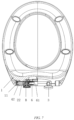
Fig. 1 is the first the structural diagram of the present disclosure; -
Fig. 2 is the second structural diagram of the present disclosure; -
Fig. 3 is an exploded view of the present disclosure; -
Fig. 4 is a transverse sectional view of the present disclosure in the locking state; -
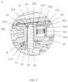
Fig. 5 is an enlarged schematic diagram of the portion A as shown inFig. 4 ; -
Fig. 6 is a partial schematic diagram of the present disclosure in the locking state; -
Fig. 7 is a partial sectional view of the present disclosure in the unlocking state; -
Fig. 8 is an enlarged schematic diagram of the portion B as shown inFig. 7 ; -
Fig. 9 is a partial schematic diagram of the present disclosure in the unlocking state; -
Fig. 10 is a structural schematic diagram of the hinge body; -
Fig. 11 is a transverse sectional view of the hinge body; -
Fig. 12 is a structural schematic diagram of the panel oil core; -
Fig. 13 is a structural schematic diagram of a locking member; -
Fig. 14 is a structural schematic diagram of a driving member; -
FIG. 15 is a structural schematic diagram of the hinge tube; -
FIG. 16 is a structural schematic diagram of the clamping fastener. - The present disclosure is further described in detail with reference to the attached drawings and specific embodiments
- As shown in
Fig. 1 to Fig. 16 , a toilet seat hinge quick disassembly and assembly device, including a fixedseat 3 and abuffer 4 detachably connected to the fixedseat 3. The device further comprising ahinge tube 6, and afixing device 5 which drives thebuffer 4 to be clamped with or separated from the fixedseat 3. And the fixingdevice 5 includes a lockingmember 51, a drivingmember 52 which drives the lockingmember 51 separated from the fixedseat 3 and aspring 53 that keeps a snap-fit of the lockingmember 51 and the fixedseat 3. The drivingmember 52 is fixedly fixed in thehinge tube 6 circumferentially. Thebuffer 4 includes ahinge body 41, and the outer circumference of thehinge body 41 is provided with anaccommodation groove 411. The drivingmember 52 is rotatably arranged in theaccommodation groove 411, the drivingmember 52 is provided with aguide sliding surface 521, the lockingmember 51 is provided with a drivingportion 511 matched with theguide sliding surface 521. The lockingmember 51 is provided with atransverse locking portion 512, and one side of thetransverse locking portion 512 is provided with aclamping hole 513 for inserting the fixedseat 3 when assembly, and the inner wall of theclamping hole 513 is provided with a clampingportion 514 which is clamped with the fixedseat 3. Thehinge body 41 is provided with amovable space 413 and anaccommodation hole 414. Thetransverse locking portion 512 is slidably arranged in themovable space 413, and one side of themovable space 413 facing theaccommodation groove 411 is provided with the first opening, the inner wall of theaccommodation groove 411 is provided with thesecond opening 415 communicated with theaccommodation hole 414. The other side of thetransverse locking portion 512 extends downward to form avertical driving rod 515 inserted in theaccommodation hole 414 after assembly. One end of thespring 54 is against on the bottom wall of theaccommodation hole 414, and the other end of thespring 54 is against on the side of thevertical driving rod 515 away from the drivingportion 511. An angle α is formed between thetransverse locking portion 512 and thevertical driving rod 515, and the angle α is a right angle or an inclined angle. The drivingportion 511 is fixedly arranged at the upper end of thevertical driving rod 515, so that the drivingpart 511 is slidably arranged on theopening 415 after assembly. Furthermore, the included angle can be obtuse angle or acute angle, as long as the other end of thespring 54 is against on thevertical driving rod 515. At the same time, thevertical driving rod 515 is slidably arranged in theaccommodation hole 414, and the fixingdevice 5 is provided in thebuffer 4. Thebuffer 4 is an independent whole with simple structure, firm parts and low manufacturing cost, which can be assembled independently and then assembled with thecover plate 1 andseat ring 2. The disassembly and replacement are simple and fast, and the buffer can operate independently in use, and is not affected by other factors and has high accuracy of disassembly and assembly. - As shown in
Figs. 4 to Figs.9 andFigs.13 to Figs.14 , in the present embodiment, the drivingmember 52 is provided with a lowposition locking portion 523 and a highposition unlocking portion 522 between the two sliding guide surfaces 521, and the sliding guidingsurface 521 is configured to connect the highposition unlocking portion 522 and the lowposition locking portion 523. Thebuffer 4 is clamped with the fixedseat 3 through the fixingdevice 5 when the drivingportion 511 contacts with the lowposition locking portion 523. The drivingportion 511 slides along the slidingsurface 521 when the drivingmember 52 is rotated, and thebuffer 4 is disconnected from the fixedseat 3 when the drivingportion 511 slides to the highposition unlocking portion 522. The slidingguide surface 521 is arranged between the highposition unlocking portion 522 and the lowposition locking portion 523. During unlocking and locking, the slidingguide surface 521 contacts with the drivingportion 511, so that the drivingportion 511 moves steadily, and the lockingmember 51 moves steadily along the axis direction of thehinge body 41. - As shown in
Figs. 4 to Figs.9 andFigs.13 to Figs.14 , in the present embodiment, the drivingmember 52 is provided with a raised lowposition limiting portion 524, and the lowposition locking portion 523 is arranged between the slidingguide surface 521 and the lowposition limiting portion 524. The two sides of the drivingportion 511 are respectively provided with alimit surface 516 matched with the lowposition limiting portion 524 and abuffer surface 517 matched with the highposition unlocking portion 522. Furthermore, thelimit surface 516 and thebuffer surface 517 are identical surfaces, which are symmetrically arranged on both sides of the drivingportion 511. As shown inFig. 6 , after assembly, the drivingportion 511 is located between the highposition unlocking portion 522 and the lowposition limiting portion 524. The lowposition limiting portion 524 is against on thelimit surface 516, and thelimit surface 516 cooperates with the low position limiting portion when theseat ring 2 is closed. The smooth surface reduces the impact force produced by the closing of the lowposition limiting portion 524, and avoids the damage of the drivingportion 511 or the lowposition limiting portion 524 caused by the long time opening and closing, while thebuffer surface 517 contacts the highposition unlocking portion 522 when theseat ring 2 is lifted up, which also acts as a buffer. Under the action of the drivingportion 511 and the slidingguide surface 521, the slidingguide surface 521 moves smoothly, so as to make the lockingmember 51 move steadily along the axis direction of thehinge body 41, such that the unlocking is achieved, and the structure is simple, the design is ingenious, and the service life of the parts is increased. - As shown in
Fig. 5 ,Fig. 8 andFig. 14 toFig. 16 , in the present embodiment, a raised clampingrib 525 is arranged on the periphery of the drivingmember 52, anaccommodation cavity 61 for accommodating thehinge body 41 is arranged in thehinge tube 6, and thefirst clamping groove 63 for inserting the clampingrib 525 after assembly is arranged on the inner wall of theaccommodation cavity 61. Athird opening 62 communicated with theaccommodation cavity 61 is respectively arranged on both sides of thehinge tube 6, and a clampingfastener 7 for fixing thebuffer 4 is provided in thethird opening 62. The outer peripheral surfaces of thehinge body 41 corresponding to two sides of thethird opening 62 are provided withannular grooves 416, and both sides of the clampingfastener 7 are provided with snappingportions 71 inserted into theannular grooves 416 after assembly, and the snappingportions 71 extend outward to form astep structure 711 which snaps the inner wall of theaccommodation cavity 61 after assembly. The fixedseat 3 includes abottom base 31 and aclamping column 32 inserted into thehinge body 41 when assembly, and the clampingfastener 7 is further provided with a throughhole 72 for theclamping column 32 to pass through during assembly. During assembly, thebuffer 4 is inserted into theaccommodation cavity 61, thefirst clamping groove 63 inserted by the clampingrib 525 makes the drivingmember 52 fixedly fixed in thehinge tube 6 circumferentially, and the drivingmember 52 rotates synchronously with the rotation of thehinge tube 6. The clampingfastener 7 is used to limit the movement of thebuffer 4 along the axis direction of thehinge body 41, and the structure is simple, and the disassembly, installation and replacement of the buffer are simple and quick. - As shown in
Fig. 5 ,Fig. 8 andFig. 10 to Fig. 11 , in the present embodiment, one end of theclamping column 32 is fixedly connected to thebottom base 31, and the outer peripheral surface of the other end of theclamping column 32 is provided with an inward depression to form a clampinggroove 321 matched with the clampingportion 514. Thehinge body 41 is provided with afirst insertion hole 412, wherein the first insertion hole is a vertical opening and is configured for inserting theclamping column 32 during assembly. Themovable space 413 is arranged at the upper end of thefirst insertion hole 412 and is communicated with thefirst insertion hole 412, and theclamping hole 513 is aligned to thefirst insertion hole 412 when the lockingmember 51 is slidably provided and snapped in thehinge body 41. While themovable space 413 is used for the insertion of thetransverse locking portion 512, it plays a guiding role on thetransverse locking portion 512 when the fixingdevice 5 is unlocked and locked. - As shown in
Fig. 3 to Fig. 8 andFig. 12 , in the present embodiment, thebuffer 4 further includes apanel oil core 42. Thehinge body 41 is further provided with asecond insertion hole 417, and thepanel oil core 42 is provided with an raisedinsertion portion 421 which is inserted into thesecond insertion hole 417 during assembly. Theseat ring 2 includes aseat ring body 21 and hingeholes 22, thehinge tube 6 is fixedly connected to theseat ring body 21 and arranged between the two hinge holes 22. One end of thepanel oil core 42 is inserted into thehinge hole 22, thepanel oil core 42 passes through thehinge hole 22 during assembly, so that theinsertion portion 421 is inserted into thesecond insertion hole 417. Thecover plate 1 is also included, the other end of thepanel oil core 42 is fixedly connected to thecover plate 1, thepanel oil core 421 is further provided with anoil core casing 422, thecover plate 1 is provided with athird insertion hole 11 for fixing theoil core casing 422. And the outer peripheral surfaces of the twooil core casings 422 are respectively provided with ananti-skid sleeve 8 and ananti-skid sheet 9. Furthermore, thehinge hole 22 is sleeved and arranged outside thebuffer 4, theoil core casing 422 is fixedly inserted into thethird insertion hole 11, so that theoil core casing 422 and thecover plate 1 rotate synchronously. And theinsertion portion 421 is arranged on the main body of thepanel oil core 42, theoil core casing 422 and the main body of thepanel oil core 42 can rotate relatively, and thepanel oil core 42 can slow down the falling speed of thecover plate 1 when thecover plate 1 is closed, which plays a buffering function, so as to reduce the impact of thecover plate 1 and theseat ring 2, thereby improving the service lift of thecover plate 1 and theseat ring 2. Theanti-skid sleeve 8 and theanti-skid sheet 9 increase the friction between theoil core casing 422 and thethird insertion hole 11, so as to prevent the relative rotation of theoil core casing 422 and thethird insertion hole 11, playing the buffering role of thepanel oil core 42, and further improve the overall use life. - As shown in
Fig. 1 to Fig. 5 , a toilet combined cover plate with a toilet seat hinge quick disassembly and assembly device, including acover plate 1 and aseat ring 2. The hingedtube 6 is fixedly connected to theseat ring 2, thecover plate 1 is rotatably connected to theseat ring 2 through thebuffer 4, and theseat ring 2 is detachably connected to the fixedseat 3 through thebuffer 4. The toilet seat hinge quick disassembly and assembly device is adopted for the toilet combined cover plate, which simplifies the disassembly and assembly process of the toilet combined cover plate, and the parts are independently assembled, and the assembly and replacement are simple and fast, which improves the user's experience. - As shown in
Fig. 1 to Fig. 5 , a toilet with a toilet seat hinge quick disassembly and assembly device, including acover plate 1, aseat ring 2, a base and a water tank. Thehinge tube 6 is fixedly connected to theseat ring 2, the water tank is fixedly arranged on the base, the fixedseat 3 is fixedly connected to the base, thecover plate 1 is rotatably connected to theseat ring 2 through abuffer 4, and theseat ring 2 is detachably connected to the fixedseat 3 through thebuffer 4. The toilet adopts the toilet seat hinge quick disassembly and assembly device to simplify the disassembly and assembly process of the toilet combined cover plate, and the parts are assembled independently, and the assembly and replacement are simple and fast, which improves the user's experience. - As shown in
Fig. 4 to Fig. 9 , a method for removing the cover plate and the seat ring of the toilet includes the following steps: - Step S1, the
cover plate 1 and theseat ring 2 are turned over so that theseat ring 2 drives the drivingmember 52 to rotate synchronously through thehinge tube 6 fixedly connected with theseat ring 2; - Step S2, the driving
portion 511 slides along theguide sliding surface 521 and slides to the highposition unlocking portion 522, while the lockingmember 51 moves axially towards one side of the fixedseat 3, so that the clampingportion 514 is separated from the fixedseat 3; - Step S3, an upward force is applied to the
cover plate 1 and theseat ring 2, so that thecover plate 1 and theseat ring 2 are disconnected from the fixedseat 3, and the disassembly is completed. - During disassembling, it is only necessary to rotate the
cover plate 1 and theseat ring 2, so that thehinge tube 6 drives the drivingmember 52 to rotate to the drivingportion 511 on the drivingmember 52, and when the highposition unlocking portion 522 is touched, the lockingmember 51 moves stably along the axis direction of thehinge body 41, so that the clampingportion 514 on the lockingmember 51 is separated from the clampinggroove 321, and theseat ring 1 and thecover plate 2 can be directly taken out, which is convenient and quick. When assembling, it only needs to insert the clampingcolumn 32 of theseat hinge 3 into thefirst insertion hole 412, and then rotating thecover plate 1 and theseat ring 2, so as to close thecover plate 1 and theseat ring 2 on the toilet to complete the assembly. The design is ingenious, the structure is simple, the disassembly and assembly is easy, and the operation can be completed by one hand, which greatly improves the user's experience.
Claims (11)
- A toilet seat hinge quick disassembly and assembly device, comprising a fixed seat (3) and a buffer (4) detachably connected to the fixed seat (3), a hinge tube (6), and a fixing device (5) driving the buffer (4) to be clamped with or separated from the fixed seat (3), and the fixing device (5) comprising a locking member (51), a driving member (52) driving the locking member (51) separated from the fixed seat (3) and a spring (53) keeping a snap-fit of the locking member (51) and the fixed seat (3), the driving member (52) is fixedly fixed in the hinge tube (6) circumferentially; wherein the buffer (4) comprises a hinge body (41), and an outer circumference of the hinge body (41) is provided with an accommodation groove (411); the driving member (52) is rotatably arranged in the accommodation groove (411), the driving member (52) is provided with a guide sliding surface (521), the locking member (51) is provided with a driving portion (511) matched with the guide sliding surface (521); the locking member (51) is provided with a transverse locking portion (512), and one side of the transverse locking portion (512) is provided with a clamping hole (513) for inserting the fixed seat (3) when assembly, an inner wall of the clamping hole (513) is provided with a clamping portion (514) clamped with the fixed seat (3); the hinge body (41) is provided with a movable space (413) and an accommodation hole (414); the transverse locking portion (512) is slidably arranged in the movable space (413), and one side of the movable space (413) facing the accommodation groove (411) is provided with a first opening, an inner wall of the accommodation groove (411) is provided with a second opening (415) communicated with the accommodation hole (414); the other side of the transverse locking portion (512) extends downward to form a vertical driving rod (515) inserted in the accommodation hole (414) after assembly; one end of the spring (54) is against on a bottom wall of the accommodation hole (414); the other end of the spring (54) is against on a side of the vertical driving rod (515) away from the driving portion (511); an angle α is formed between the transverse locking portion (512) and the vertical driving rod (515), and the angle α is a right angle or an inclined angle; a raised clamping rib (525) is arranged on a periphery of the driving member (52), an accommodation cavity (61) for accommodating the hinge body (41) is arranged in the hinge tube (6), and a first clamping groove (63) for inserting the clamping rib (525) is arranged on an inner wall of the accommodation cavity (61); wherein a third opening (62) communicated with the accommodation cavity (61) is respectively arranged on both sides of the hinge tube (6), characterised in that a clamping fastener (7) for fixing the buffer (4) is provided in the third opening (62).
- The toilet seat hinge quick disassembly and assembly device according to claim 1, which is characterized in that : the driving member (52) is provided with a low position locking portion (523) and a high position unlocking portion (522) between the two sliding guide surfaces (521), and the sliding guiding surface (521) is configured to connect the high position unlocking portion (522) and the low position locking portion (523); the buffer (4) is clamped with the fixed seat (3) through the fixing device (5) when the driving portion (511) contacts with the low position locking portion (523); the driving portion (511) slides along the sliding surface (521) when the driving member (52) is rotated; the buffer (4) is disconnected from the fixed seat (3) when the driving portion (511) slides to the high position unlocking portion (522).
- The toilet seat hinge quick disassembly and assembly device according to claim 2, which is characterized in that the driving member (52) is provided with a raised low position limiting portion (524), and the low position locking portion (523) is arranged between the sliding guide surface (521) and the low position limiting portion (524).
- The toilet seat hinge quick disassembly and assembly device according to claim 3, which is characterized in that two sides of the driving portion (511) are provided with a limit surface (516) matched with the low position limiting portion (524) and a buffer surface (517) matched with the high position unlocking portion (522).
- The toilet seat hinge quick disassembly and assembly device according to claim 1, which is characterized in that an outer peripheral surfaces of the hinge body (41) corresponding to two sides of the third opening (62) are provided with annular grooves (416), both sides of the clamping fastener (7) are provided with snapping portions (71) inserted into the annular grooves (416) after assembly, and the snapping portions (71) extend outward to form a step structure (711) that snaps the inner wall of the accommodation cavity (61) after assembly; the fixed seat (3) comprises a bottom base (31) and a clamping column (32) inserted into the hinge body (41) when assembly; the clamping fastener (7) is provided with a through hole (72) for the clamping column (32) to pass through during assembly.
- The toilet seat hinge quick disassembly and assembly device according to claim 5, which is characterized in that one end of the clamping column (32) is fixedly connected to the bottom base (31), and an outer peripheral surface of the other end of the clamping column (32) is provided with an inward depression to form a clamping groove (321) matched with the clamping portion (514).
- The toilet seat hinge quick disassembly and assembly device according to claim 6, which is characterized in that : the hinge body (41) is provided with a first insertion hole (412), wherein the first insertion hole is a vertical opening and is configured for inserting the clamping column (32) during assembly; the movable space (413) is arranged at an upper end of the first insertion hole (412) and is communicated with the first insertion hole (412), and the clamping hole (513) is aligned to the first insertion hole (412) when the locking member (51) is slidably provided and snapped in the hinge body (41).
- The toilet seat hinge quick disassembly and assembly device according to claim 7, which is characterized in that the driving portion (511) is fixedly arranged at an upper end of the vertical driving rod (515), so that the driving portion (511) is slidably arranged on the opening (415) after assembly.
- The toilet seat hinge quick disassembly and assembly device according to claim 8, which is characterized in that the buffer (4) comprises a panel oil core (42), the hinge body (41) is provided with a second insertion hole (417), the panel oil core (42) is provided with an raised insertion portion (421) inserted into the second insertion hole (417) during assembly; the seat ring (2) comprises a seat ring body and hinge holes (22), the hinge tube (6) is fixedly connected to the seat ring body (21) and arranged between the two hinge holes (22); one end of the panel oil core (42) is inserted into the hinge hole (22), the panel oil core (42) passes through the hinge hole (22) during assembly, so that the insertion portion (421) is inserted into the second insertion hole (417).
- The toilet combined cover plate with a toilet seat hinge quick disassembly and assembly device according to any one of claims 1-9, comprising a cover plate (1) and a seat ring (2), which is characterized in that a hinged tube (6) is fixedly connected to the seat ring (2), the cover plate (1) is rotatably connected to the seat ring (2) through a buffer (4), and the seat ring (2) is detachably connected to the fixed seat (3) through the buffer (4).
- The toilet with a toilet seat hinge quick disassembly and assembly device according to any one of claims 1-9, comprising a cover plate (1), a seat ring (2), a base and a water tank, which is characterized in that a hinge tube (6) is fixedly connected to the seat ring (2), the water tank is fixedly arranged on the base, a fixed seat (3) is fixedly connected to the base, the cover plate (1) is rotatably connected to the seat ring (2) through a buffer (4), and the seat ring (2) is detachably connected to the fixed seat (3) through the buffer (4).
Applications Claiming Priority (1)
| Application Number | Priority Date | Filing Date | Title |
|---|---|---|---|
| CN202011370577.3A CN112515523B (en) | 2020-11-30 | 2020-11-30 | Toilet seat hinge quick-release device and application thereof |
Publications (3)
| Publication Number | Publication Date |
|---|---|
| EP4005446A1 EP4005446A1 (en) | 2022-06-01 |
| EP4005446C0 EP4005446C0 (en) | 2025-04-23 |
| EP4005446B1 true EP4005446B1 (en) | 2025-04-23 |
Family
ID=74105769
Family Applications (1)
| Application Number | Title | Priority Date | Filing Date |
|---|---|---|---|
| EP20217435.5A Active EP4005446B1 (en) | 2020-11-30 | 2020-12-28 | Toilet seat hinge quick disassembly and assembly device and its application |
Country Status (3)
| Country | Link |
|---|---|
| EP (1) | EP4005446B1 (en) |
| CN (1) | CN112515523B (en) |
| ES (1) | ES3024408T3 (en) |
Families Citing this family (2)
| Publication number | Priority date | Publication date | Assignee | Title |
|---|---|---|---|---|
| CN113303696B (en) * | 2021-06-01 | 2025-09-12 | 厦门倍杰特科技有限公司 | Easy-to-detach parent-child cover and toilet |
| CN119033267A (en) * | 2024-08-13 | 2024-11-29 | 泉州科牧智能厨卫有限公司 | Intelligent closestool, cover plate, display screen assembly and disassembly and assembly method thereof |
Family Cites Families (12)
| Publication number | Priority date | Publication date | Assignee | Title |
|---|---|---|---|---|
| WO2011035657A1 (en) * | 2009-09-28 | 2011-03-31 | 厦门豪帝卫浴工业有限公司 | Fast assembling and disassembling mechanism for closet cover set |
| CN102764093B (en) * | 2012-06-21 | 2014-08-06 | 彭东 | Closestool and connecting device for cover plate and seat body of closestool |
| CN203263271U (en) * | 2013-05-27 | 2013-11-06 | 彭东 | Connecting mechanism of closestool cover plate and closestool seat body |
| CN203861109U (en) | 2014-04-23 | 2014-10-08 | 彭东 | Fast dismounting and connecting mechanism for toilet bowl cover plate and toilet bowl seat |
| CN204181547U (en) | 2014-10-21 | 2015-03-04 | 赵励平 | A simple press disassembly device for a toilet seat cover |
| CN205197893U (en) * | 2015-11-20 | 2016-05-04 | 厦门瑞尔特卫浴科技股份有限公司 | Quick detach mechanism of lavatory lid and pedestal and have apron of this mechanism |
| CN106419713A (en) * | 2016-11-03 | 2017-02-22 | 厦门瑞尔特卫浴科技股份有限公司 | Cover plate mechanism unlocked at preset angle |
| US10285546B2 (en) * | 2017-02-13 | 2019-05-14 | Topseat International, Inc. | System and method for removably mounting toilet seat to toilet bowl |
| CN208274529U (en) * | 2017-08-22 | 2018-12-25 | 中山市美图塑料工业有限公司 | A quick-detachable cover assembly |
| CN209203115U (en) * | 2018-07-25 | 2019-08-06 | 中山市美图塑料工业有限公司 | A cover plate quick release structure |
| CN210300827U (en) * | 2019-05-31 | 2020-04-14 | 中山市美图塑料工业有限公司 | Detachable toilet cover plate with top button structure |
| CN110720855B (en) * | 2019-10-22 | 2025-04-18 | 海益(厦门)建材工业有限公司 | Quick disassembly and assembly mechanism of toilet cover |
-
2020
- 2020-11-30 CN CN202011370577.3A patent/CN112515523B/en active Active
- 2020-12-28 ES ES20217435T patent/ES3024408T3/en active Active
- 2020-12-28 EP EP20217435.5A patent/EP4005446B1/en active Active
Also Published As
| Publication number | Publication date |
|---|---|
| EP4005446C0 (en) | 2025-04-23 |
| CN112515523B (en) | 2022-08-19 |
| ES3024408T3 (en) | 2025-06-04 |
| CN112515523A (en) | 2021-03-19 |
| EP4005446A1 (en) | 2022-06-01 |
Similar Documents
| Publication | Publication Date | Title |
|---|---|---|
| EP4005446A1 (en) | Toilet seat hinge quick disassembly and assembly device and its application | |
| JP5433466B2 (en) | Sliding assist device | |
| CN119466438A (en) | Double lock core | |
| CN111946181A (en) | Hinge structure | |
| CN203263271U (en) | Connecting mechanism of closestool cover plate and closestool seat body | |
| CN209733816U (en) | Rotary dismounting type toilet cover plate support | |
| KR100737148B1 (en) | Reversing Equipment for Operation Direction and Lid Switching Device Which Applies it | |
| CN107960387B (en) | Drum wheel capable of quickly opening side cover | |
| CN109222734A (en) | A kind of rotation reassembling type lavatory lid bracket | |
| CN110578427B (en) | Door lock opening device with clutch | |
| CN110607949B (en) | Lock body power assembly with clutch | |
| CN221322042U (en) | Door handle assembly | |
| CN220735268U (en) | Quick assembly disassembly's closestool seat circle | |
| CN110566054B (en) | Clutch structure suitable for door lock | |
| CN109653595B (en) | Lock mechanism capable of reversing left and right | |
| CN215457582U (en) | Daughter board capable of being rapidly disassembled and assembled | |
| CN215728963U (en) | Optical fiber connector | |
| US12435541B2 (en) | Lockset and door lock | |
| CN210948058U (en) | Door lock opening device with clutch | |
| CN211008016U (en) | Lock body power assembly with clutch | |
| CN111794607B (en) | Automatic locks | |
| CN114541895A (en) | An outer door handle, a vehicle, and an assembly method for an outer door handle | |
| CN211796164U (en) | Dismounting structure of closestool cover plate | |
| CN211796163U (en) | Easy-to-dismount structure of toilet cover plate | |
| CN205476872U (en) | Intelligence lock clutch subassembly |
Legal Events
| Date | Code | Title | Description |
|---|---|---|---|
| PUAI | Public reference made under article 153(3) epc to a published international application that has entered the european phase |
Free format text: ORIGINAL CODE: 0009012 |
|
| STAA | Information on the status of an ep patent application or granted ep patent |
Free format text: STATUS: THE APPLICATION HAS BEEN PUBLISHED |
|
| AK | Designated contracting states |
Kind code of ref document: A1 Designated state(s): AL AT BE BG CH CY CZ DE DK EE ES FI FR GB GR HR HU IE IS IT LI LT LU LV MC MK MT NL NO PL PT RO RS SE SI SK SM TR |
|
| STAA | Information on the status of an ep patent application or granted ep patent |
Free format text: STATUS: REQUEST FOR EXAMINATION WAS MADE |
|
| 17P | Request for examination filed |
Effective date: 20221104 |
|
| RBV | Designated contracting states (corrected) |
Designated state(s): AL AT BE BG CH CY CZ DE DK EE ES FI FR GB GR HR HU IE IS IT LI LT LU LV MC MK MT NL NO PL PT RO RS SE SI SK SM TR |
|
| GRAP | Despatch of communication of intention to grant a patent |
Free format text: ORIGINAL CODE: EPIDOSNIGR1 |
|
| STAA | Information on the status of an ep patent application or granted ep patent |
Free format text: STATUS: GRANT OF PATENT IS INTENDED |
|
| INTG | Intention to grant announced |
Effective date: 20250131 |
|
| RIN1 | Information on inventor provided before grant (corrected) |
Inventor name: ZHANG, HAI Inventor name: HUANG, HAOJIA Inventor name: ZHOU, WENHUI |
|
| GRAS | Grant fee paid |
Free format text: ORIGINAL CODE: EPIDOSNIGR3 |
|
| GRAA | (expected) grant |
Free format text: ORIGINAL CODE: 0009210 |
|
| STAA | Information on the status of an ep patent application or granted ep patent |
Free format text: STATUS: THE PATENT HAS BEEN GRANTED |
|
| AK | Designated contracting states |
Kind code of ref document: B1 Designated state(s): AL AT BE BG CH CY CZ DE DK EE ES FI FR GB GR HR HU IE IS IT LI LT LU LV MC MK MT NL NO PL PT RO RS SE SI SK SM TR |
|
| REG | Reference to a national code |
Ref country code: GB Ref legal event code: FG4D |
|
| REG | Reference to a national code |
Ref country code: CH Ref legal event code: EP |
|
| REG | Reference to a national code |
Ref country code: DE Ref legal event code: R096 Ref document number: 602020049876 Country of ref document: DE |
|
| REG | Reference to a national code |
Ref country code: IE Ref legal event code: FG4D |
|
| REG | Reference to a national code |
Ref country code: ES Ref legal event code: FG2A Ref document number: 3024408 Country of ref document: ES Kind code of ref document: T3 Effective date: 20250604 |
|
| U01 | Request for unitary effect filed |
Effective date: 20250430 |
|
| U07 | Unitary effect registered |
Designated state(s): AT BE BG DE DK EE FI FR IT LT LU LV MT NL PT RO SE SI Effective date: 20250508 |
|
| PG25 | Lapsed in a contracting state [announced via postgrant information from national office to epo] |
Ref country code: NO Free format text: LAPSE BECAUSE OF FAILURE TO SUBMIT A TRANSLATION OF THE DESCRIPTION OR TO PAY THE FEE WITHIN THE PRESCRIBED TIME-LIMIT Effective date: 20250723 Ref country code: GR Free format text: LAPSE BECAUSE OF FAILURE TO SUBMIT A TRANSLATION OF THE DESCRIPTION OR TO PAY THE FEE WITHIN THE PRESCRIBED TIME-LIMIT Effective date: 20250724 |
|
| PG25 | Lapsed in a contracting state [announced via postgrant information from national office to epo] |
Ref country code: PL Free format text: LAPSE BECAUSE OF FAILURE TO SUBMIT A TRANSLATION OF THE DESCRIPTION OR TO PAY THE FEE WITHIN THE PRESCRIBED TIME-LIMIT Effective date: 20250423 |
|
| PG25 | Lapsed in a contracting state [announced via postgrant information from national office to epo] |
Ref country code: HR Free format text: LAPSE BECAUSE OF FAILURE TO SUBMIT A TRANSLATION OF THE DESCRIPTION OR TO PAY THE FEE WITHIN THE PRESCRIBED TIME-LIMIT Effective date: 20250423 |
|
| PG25 | Lapsed in a contracting state [announced via postgrant information from national office to epo] |
Ref country code: RS Free format text: LAPSE BECAUSE OF FAILURE TO SUBMIT A TRANSLATION OF THE DESCRIPTION OR TO PAY THE FEE WITHIN THE PRESCRIBED TIME-LIMIT Effective date: 20250723 |
|
| PG25 | Lapsed in a contracting state [announced via postgrant information from national office to epo] |
Ref country code: IS Free format text: LAPSE BECAUSE OF FAILURE TO SUBMIT A TRANSLATION OF THE DESCRIPTION OR TO PAY THE FEE WITHIN THE PRESCRIBED TIME-LIMIT Effective date: 20250823 |
|
| U20 | Renewal fee for the european patent with unitary effect paid |
Year of fee payment: 6 Effective date: 20251111 |
|
| PGFP | Annual fee paid to national office [announced via postgrant information from national office to epo] |
Ref country code: GB Payment date: 20251112 Year of fee payment: 6 |
|
| PG25 | Lapsed in a contracting state [announced via postgrant information from national office to epo] |
Ref country code: SM Free format text: LAPSE BECAUSE OF FAILURE TO SUBMIT A TRANSLATION OF THE DESCRIPTION OR TO PAY THE FEE WITHIN THE PRESCRIBED TIME-LIMIT Effective date: 20250423 |
|
| PG25 | Lapsed in a contracting state [announced via postgrant information from national office to epo] |
Ref country code: CZ Free format text: LAPSE BECAUSE OF FAILURE TO SUBMIT A TRANSLATION OF THE DESCRIPTION OR TO PAY THE FEE WITHIN THE PRESCRIBED TIME-LIMIT Effective date: 20250423 |
|
| PG25 | Lapsed in a contracting state [announced via postgrant information from national office to epo] |
Ref country code: SK Free format text: LAPSE BECAUSE OF FAILURE TO SUBMIT A TRANSLATION OF THE DESCRIPTION OR TO PAY THE FEE WITHIN THE PRESCRIBED TIME-LIMIT Effective date: 20250423 |
|
| PLBE | No opposition filed within time limit |
Free format text: ORIGINAL CODE: 0009261 |
|
| STAA | Information on the status of an ep patent application or granted ep patent |
Free format text: STATUS: NO OPPOSITION FILED WITHIN TIME LIMIT |
|
| REG | Reference to a national code |
Ref country code: CH Ref legal event code: L10 Free format text: ST27 STATUS EVENT CODE: U-0-0-L10-L00 (AS PROVIDED BY THE NATIONAL OFFICE) Effective date: 20260304 |
|
| 26N | No opposition filed |
Effective date: 20260126 |
|
| PGFP | Annual fee paid to national office [announced via postgrant information from national office to epo] |
Ref country code: ES Payment date: 20260105 Year of fee payment: 6 |
|
| PG25 | Lapsed in a contracting state [announced via postgrant information from national office to epo] |
Ref country code: MC Free format text: LAPSE BECAUSE OF FAILURE TO SUBMIT A TRANSLATION OF THE DESCRIPTION OR TO PAY THE FEE WITHIN THE PRESCRIBED TIME-LIMIT Effective date: 20250423 |
|
| REG | Reference to a national code |
Ref country code: CH Ref legal event code: H13 Free format text: ST27 STATUS EVENT CODE: U-0-0-H10-H13 (AS PROVIDED BY THE NATIONAL OFFICE) Effective date: 20260723 |