EP4005360A1 - Hydraulic steering device of agricultural work vehicle - Google Patents
Hydraulic steering device of agricultural work vehicle Download PDFInfo
- Publication number
- EP4005360A1 EP4005360A1 EP20844179.0A EP20844179A EP4005360A1 EP 4005360 A1 EP4005360 A1 EP 4005360A1 EP 20844179 A EP20844179 A EP 20844179A EP 4005360 A1 EP4005360 A1 EP 4005360A1
- Authority
- EP
- European Patent Office
- Prior art keywords
- steering
- automatic
- working fluid
- blocking
- line
- Prior art date
- Legal status (The legal status is an assumption and is not a legal conclusion. Google has not performed a legal analysis and makes no representation as to the accuracy of the status listed.)
- Granted
Links
Images












Classifications
-
- B—PERFORMING OPERATIONS; TRANSPORTING
- B62—LAND VEHICLES FOR TRAVELLING OTHERWISE THAN ON RAILS
- B62D—MOTOR VEHICLES; TRAILERS
- B62D1/00—Steering controls, i.e. means for initiating a change of direction of the vehicle
- B62D1/02—Steering controls, i.e. means for initiating a change of direction of the vehicle vehicle-mounted
- B62D1/22—Alternative steering-control elements, e.g. for teaching purposes
-
- B—PERFORMING OPERATIONS; TRANSPORTING
- B62—LAND VEHICLES FOR TRAVELLING OTHERWISE THAN ON RAILS
- B62D—MOTOR VEHICLES; TRAILERS
- B62D5/00—Power-assisted or power-driven steering
- B62D5/06—Power-assisted or power-driven steering fluid, i.e. using a pressurised fluid for most or all the force required for steering a vehicle
- B62D5/062—Details, component parts
-
- B—PERFORMING OPERATIONS; TRANSPORTING
- B62—LAND VEHICLES FOR TRAVELLING OTHERWISE THAN ON RAILS
- B62D—MOTOR VEHICLES; TRAILERS
- B62D5/00—Power-assisted or power-driven steering
- B62D5/06—Power-assisted or power-driven steering fluid, i.e. using a pressurised fluid for most or all the force required for steering a vehicle
- B62D5/065—Power-assisted or power-driven steering fluid, i.e. using a pressurised fluid for most or all the force required for steering a vehicle characterised by specially adapted means for varying pressurised fluid supply based on need, e.g. on-demand, variable assist
-
- A—HUMAN NECESSITIES
- A01—AGRICULTURE; FORESTRY; ANIMAL HUSBANDRY; HUNTING; TRAPPING; FISHING
- A01B—SOIL WORKING IN AGRICULTURE OR FORESTRY; PARTS, DETAILS, OR ACCESSORIES OF AGRICULTURAL MACHINES OR IMPLEMENTS, IN GENERAL
- A01B69/00—Steering of agricultural machines or implements; Guiding agricultural machines or implements on a desired track
- A01B69/007—Steering or guiding of agricultural vehicles, e.g. steering of the tractor to keep the plough in the furrow
-
- A—HUMAN NECESSITIES
- A01—AGRICULTURE; FORESTRY; ANIMAL HUSBANDRY; HUNTING; TRAPPING; FISHING
- A01B—SOIL WORKING IN AGRICULTURE OR FORESTRY; PARTS, DETAILS, OR ACCESSORIES OF AGRICULTURAL MACHINES OR IMPLEMENTS, IN GENERAL
- A01B69/00—Steering of agricultural machines or implements; Guiding agricultural machines or implements on a desired track
- A01B69/007—Steering or guiding of agricultural vehicles, e.g. steering of the tractor to keep the plough in the furrow
- A01B69/008—Steering or guiding of agricultural vehicles, e.g. steering of the tractor to keep the plough in the furrow automatic
-
- B—PERFORMING OPERATIONS; TRANSPORTING
- B62—LAND VEHICLES FOR TRAVELLING OTHERWISE THAN ON RAILS
- B62D—MOTOR VEHICLES; TRAILERS
- B62D5/00—Power-assisted or power-driven steering
- B62D5/06—Power-assisted or power-driven steering fluid, i.e. using a pressurised fluid for most or all the force required for steering a vehicle
- B62D5/07—Supply of pressurised fluid for steering also supplying other consumers ; control thereof
-
- B—PERFORMING OPERATIONS; TRANSPORTING
- B62—LAND VEHICLES FOR TRAVELLING OTHERWISE THAN ON RAILS
- B62D—MOTOR VEHICLES; TRAILERS
- B62D5/00—Power-assisted or power-driven steering
- B62D5/06—Power-assisted or power-driven steering fluid, i.e. using a pressurised fluid for most or all the force required for steering a vehicle
- B62D5/08—Power-assisted or power-driven steering fluid, i.e. using a pressurised fluid for most or all the force required for steering a vehicle characterised by type of steering valve used
-
- B—PERFORMING OPERATIONS; TRANSPORTING
- B62—LAND VEHICLES FOR TRAVELLING OTHERWISE THAN ON RAILS
- B62D—MOTOR VEHICLES; TRAILERS
- B62D5/00—Power-assisted or power-driven steering
- B62D5/06—Power-assisted or power-driven steering fluid, i.e. using a pressurised fluid for most or all the force required for steering a vehicle
- B62D5/09—Power-assisted or power-driven steering fluid, i.e. using a pressurised fluid for most or all the force required for steering a vehicle characterised by means for actuating valves
- B62D5/093—Telemotor driven by steering wheel movement
-
- B—PERFORMING OPERATIONS; TRANSPORTING
- B62—LAND VEHICLES FOR TRAVELLING OTHERWISE THAN ON RAILS
- B62D—MOTOR VEHICLES; TRAILERS
- B62D5/00—Power-assisted or power-driven steering
- B62D5/06—Power-assisted or power-driven steering fluid, i.e. using a pressurised fluid for most or all the force required for steering a vehicle
- B62D5/30—Safety devices, e.g. alternate emergency power supply or transmission means to ensure steering upon failure of the primary steering means
Definitions
- the present invention relates to an agricultural vehicle used to grow crops necessary for human life by using land.
- Agricultural vehicles are used to grow crops necessary for human life by using land.
- the agricultural vehicles include a combine harvester, a tractor, a rice transplanter, and the like.
- the combine harvester performs tasks of reaping and threshing crops such as rice, barley, wheat, and soybeans.
- the tractor uses traction to perform a task necessary to grow crops.
- the rice transplanter performs a task of transplanting rice seedlings, which are raised in a rice seedbed or a seedling tray, to a paddy field.
- Such an agricultural vehicle includes a steering device for changing a traveling direction as necessary during a work process.
- the steering device changes a direction of wheels provided in the agricultural vehicle to change the traveling direction thereof.
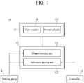
- FIG. 1 is a schematic block diagram of a steering device for an agricultural vehicle according to a related art.
- a steering device (10) of an agricultural vehicle includes a steering pump (11) and a steering adjuster (12).
- the steering pump (11) supplies a working fluid to the steering adjuster (12).
- the steering pump (11) may use a driving force generated by an engine (not illustrated) of the agricultural vehicle to transfer the working fluid.
- the working fluid is stored in a storage tank (not illustrated) of the agricultural vehicle.
- the steering adjuster (12) is connected to the steering pump (11) and a steering cylinder (13).
- the steering cylinder (13) changes a direction of wheels provided in the agricultural vehicle.
- the steering adjuster (12) supplies the working fluid supplied from the steering pump (11) to any one cylinder of a first cylinder (131) and a second cylinder (132) of the steering cylinder (13). In this case, the steering adjuster (12) discharges the working fluid from the other cylinder. Accordingly, the steering adjuster (12) may adjust a moving direction of a cylinder rod (not illustrated) of the cylinders (131, 132) to change the direction of the wheels, thus changing a traveling direction of the agricultural vehicle.
- the steering adjuster (12) includes a manual steering unit (121) and an automatic steering unit (122).
- the manual steering unit (121) is connected to the steering pump (11).
- the manual steering unit (121) supplies the working fluid supplied from the steering pump (11) to the first cylinder (131) or the second cylinder (132) according to a direction of rotation of the steering wheel. That is, the manual steering unit (121) changes the traveling direction of the agricultural vehicle according to manual steering by the driver.
- the automatic steering unit (122) is connected to the steering pump (11).
- the automatic steering unit (122) supplies the working fluid supplied from the steering pump (11) to the first cylinder (131) or the second cylinder (132) according to control by a controller (14).
- the controller (14) controls the automatic steering unit (122) so that the agricultural vehicle travels along a predetermined traveling path. That is, the automatic steering unit (122) changes the traveling direction of the agricultural vehicle according to automatic steering by the controller 14.
- the steering device (10) of the agricultural vehicle according to the related art in a case in which, while the traveling direction of the agricultural vehicle is changed according to the automatic steering, a change occurs in a working condition such as when an unexpected obstacle appears in a predetermined traveling path, even when the driver manipulates the steering wheel, the automatic steering is not changed to the manual steering, and the steering device (10) reaches a state in which the manual steering and the automatic steering simultaneously change the traveling direction of the agricultural vehicle. Accordingly, the steering device (10) of the agricultural vehicle according to the related art has a problem in that its ability to handle a change in a working condition is degraded.
- the present invention is directed to providing a hydraulic steering device for an agricultural vehicle that has an improved ability to handle a change in a working condition.
- the present invention may include the following configurations.
- a hydraulic steering device for an agricultural vehicle may include a steering pump configured to supply a working fluid, an automatic steering unit connected to the steering pump and configured to, as automatic steering is performed by a controller, use the working fluid supplied from the steering pump to change a traveling direction of the agricultural vehicle, a manual steering unit connected to the steering pump and configured to, as manual steering is performed by manipulation of a steering wheel, use the working fluid supplied from the steering pump to change the traveling direction of the agricultural vehicle, and an automatic blocking unit connected to the automatic steering unit and configured to, according to whether the manual steering is performed, selectively block a working fluid for the automatic steering from being supplied to a steering cylinder of the agricultural vehicle.
- the automatic blocking unit may allow the working fluid for the automatic steering to be supplied to the steering cylinder but may, when the manual steering is performed, use a portion of the working fluid supplied from the steering pump to the manual steering unit to block the working fluid for the automatic steering from being supplied to the steering cylinder.
- the present invention is implemented to change a traveling direction according to manual steering when the manual steering is performed while automatic steering is performed. Therefore, an ability to handle a change in a working condition can be improved, and thus, the risk of accidents can also be lowered.
- a flowing direction of a working fluid is indicated by an arrow.
- a solid arrow marked on a solid hydraulic line indicates a flowing direction of a working fluid supplied from a steering pump or a flowing direction of a working fluid supplied to a steering cylinder.
- a dotted arrow marked on the solid hydraulic line indicates a flowing direction of a working fluid discharged from the steering cylinder or a flowing direction of a working fluid discharged to an external device.
- a dotted arrow marked on a dotted hydraulic line indicates a flowing direction of a working fluid for moving a valve.
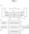
- a hydraulic steering device 1 for an agricultural vehicle according to the present invention is included in an agricultural vehicle 100 such as a tractor, a combine harvester, and a rice transplanter.
- the agricultural vehicle 100 includes a traveling part 110 for traveling and a steering cylinder 120 for changing a traveling direction.
- the steering cylinder 120 may change a direction of wheels 111 and 111' of the traveling part 110 to change a traveling direction of the agricultural vehicle 100 (hereinafter referred to as "the traveling direction").
- the steering cylinder 120 operates in a hydraulic manner using a working fluid.
- the hydraulic steering device 1 for an agricultural vehicle according to the present invention adjusts supply and discharge of a working fluid to and from the steering cylinder 120, thus being responsible for changing the traveling direction.
- the hydraulic steering device 1 for an agricultural vehicle according to the present invention may change the traveling direction through manual steering by manipulation of a steering wheel (not illustrated) and automatic steering by a predetermined traveling path.
- the manual steering may be performed by a driver of the agricultural vehicle 100.
- the automatic steering may be performed by a controller 130 of the agricultural vehicle 100.
- a traveling path according to a working condition and the like may be stored in the controller 130.
- the hydraulic steering device 1 for an agricultural vehicle includes a steering pump 2 configured to supply a working fluid, an automatic steering unit 3 configured to change the traveling direction according to the automatic steering, a manual steering unit 4 configured to change the traveling direction according to the manual steering, and an automatic blocking unit 5 configured to allow the manual steering to be performed first among the automatic steering and the manual steering.
- the automatic steering unit 3 is connected to the steering pump 2. As illustrated in FIG. 3 , as the automatic steering is performed, the automatic steering unit 3 changes the traveling direction using the working fluid supplied from the steering pump 2. In this case, the working fluid supplied by the steering pump 2 is supplied to the steering cylinder 120 via the automatic steering unit 3. A working fluid discharged from the steering cylinder 120 is discharged to an external device 140 via the automatic steering unit 3.
- the external device 140 may be included in the agricultural vehicle 100 and operate using the working fluid.
- the external device 140 may be a transmission.
- the external device 140 may also be a storage tank configured to store the working fluid.
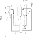
- the manual steering unit 4 is connected to the steering pump 2. As illustrated in FIG. 4 , as the manual steering is performed, the manual steering unit 4 changes the traveling direction using the working fluid supplied from the steering pump 2. In this case, the working fluid supplied by the steering pump 2 is supplied to the steering cylinder 120 via the manual steering unit 4. The working fluid discharged from the steering cylinder 120 is discharged to the external device 140 via the manual steering unit 4.
- the manual steering unit 4 may be directly connected to the steering pump 2.
- the manual steering unit 4 being directly connected to the steering pump 2 means that a component capable of changing a flowing direction of a working fluid is not installed between the manual steering unit 4 and the steering pump 2. Therefore, a case in which a component, such as a check valve, that does not change a flowing direction of a working fluid is installed between the manual steering unit 4 and the steering pump 2 should also be interpreted as the manual steering unit 4 being directly connected to the steering pump 2.
- the automatic blocking unit 5 is connected to each of the manual steering unit 4 and the automatic steering unit 3.
- the automatic blocking unit 5 may, according to whether the manual steering is performed, selectively block a working fluid for the automatic steering from being supplied to the steering cylinder 120.
- the working fluid for the automatic steering refers to a working fluid that is supplied from the steering pump 2 to the steering cylinder 120 via the automatic steering unit 3.
- the working fluid for the automatic steering may be supplied from the steering pump 2 to the automatic steering unit 3.
- the working fluid for the automatic steering may also be supplied from the automatic steering unit 3 to the steering cylinder 120.
- the automatic blocking unit 5 allows the working fluid for the automatic steering to be supplied to the steering cylinder 120.
- the automatic blocking unit 5 uses a portion of the working fluid supplied to the manual steering unit 4 to block the working fluid for the automatic steering from being supplied to the steering cylinder 120. Accordingly, the working fluid is not able to be supplied to the steering cylinder 120 through the automatic steering unit 3.
- the hydraulic steering device 1 for an agricultural vehicle according to the present invention is implemented so that, when the manual steering is performed while the automatic steering is performed, the traveling direction is changed according to the manual steering using the automatic blocking unit 5. That is, the hydraulic steering device 1 for an agricultural vehicle according to the present invention is implemented so that the manual steering is performed first among the automatic steering and the manual steering. Therefore, the hydraulic steering device 1 for an agricultural vehicle according to the present invention is implemented so that, when a change in a working condition occurs such as when an unexpected obstacle appears in a predetermined traveling path according to the automatic steering, the automatic steering is changed to the manual steering just by the driver turning the steering wheel. Accordingly, the hydraulic steering device 1 for an agricultural vehicle according to the present invention is able to improve its ability to handle a change in a working condition and thus lower the risk of accidents.
- the steering pump 2 supplies a working fluid.
- the steering pump 2 may be connected to each of the automatic steering unit 3 and the manual steering unit 4.
- the steering pump 2 may be connected to each of the automatic steering unit 3 and the manual steering unit 4 through a pump supply line 2a.
- the steering pump 2 may operate using a driving force generated by an engine (not illustrated) of the agricultural vehicle 100.
- the steering pump 2 may be connected to a storage tank (not illustrated) in which a working fluid is stored.
- the working fluid may be oil.
- the automatic steering unit 3 changes the traveling direction as the automatic steering is performed.
- the automatic steering unit 3 may be connected to the steering pump 2.
- the automatic steering unit 3 may be connected to the steering pump 2 through an automatic supply line 3a.
- the automatic supply line 3a may be connected to the pump supply line 2a and may be connected to the steering pump 2 through the pump supply line 2a.
- the automatic steering unit 3 may be connected to an external discharge line 6.
- the external discharge line 6 is connected to the external device 140 to discharge the working fluid discharged from the steering cylinder 120 to the external device 140. Therefore, as the automatic steering is performed, the working fluid discharged from the steering cylinder 120 may be discharged to the external discharge line 6 through the automatic steering unit 3 and then be discharged to the external device 140 through the external discharge line 6.
- the automatic steering unit 3 may be connected to the external discharge line 6 through an automatic discharge line 3b.
- the steering cylinder 120 may include a first hydraulic chamber 120a, a second hydraulic chamber 120b, and a steering rod 120c.
- first hydraulic chamber 120a and the second hydraulic chamber 120b may be implemented through a single hydraulic cylinder.
- first hydraulic chamber 120a and the second hydraulic chamber 120b may also be implemented through different hydraulic cylinders.
- a first hydraulic cylinder having the first hydraulic chamber 120a and a second hydraulic cylinder having the second hydraulic chamber 120b may be disposed in opposite directions.
- the first hydraulic cylinder may move a first steering rod according to whether the first hydraulic chamber 120a is filled with a working fluid or whether a working fluid is discharged from the first hydraulic chamber 120a, thereby changing the direction of the wheel 111.
- the second hydraulic cylinder may move a second steering rod according to whether the second hydraulic chamber 120b is filled with a working fluid or whether a working fluid is discharged from the second hydraulic chamber 120b, thereby changing the direction of the wheel 111'.
- the automatic steering unit 3 may supply a working fluid to any one of the first hydraulic chamber 120a and the second hydraulic chamber 120b and, simultaneously, discharge a working fluid from the other one of the first hydraulic chamber 120a and the second hydraulic chamber 120b.
- the working fluid discharged from the steering cylinder 120 may be supplied to the external discharge line 6 through the automatic discharge line 3b and may be discharged to the external device 140 through the external discharge line 6.
- the automatic steering unit 3 may be connected to the first hydraulic chamber 120a through a first steering line 120d.
- the automatic steering unit 3 may be connected to the second hydraulic chamber 120b through a second steering line 120e.
- the automatic steering unit 3 may include an automatic steering valve 31.
- the automatic steering valve 31 moves according to the automatic steering.
- the automatic steering valve 31 may move according to control by the controller 130 (see FIG. 2 ).
- the automatic steering valve 31 may move to change a flowing path of the working fluid supplied from the steering pump 2 according to the automatic steering.
- the automatic steering valve 31 may include a first automatic steering mechanism 311, a second automatic steering mechanism 312, and a third automatic steering mechanism 313.
- the first automatic steering mechanism 311 blocks the working fluid supplied from the steering pump 2 from being supplied to the steering cylinder 120. As illustrated in FIG. 5 , as the automatic steering valve 31 moves, the first automatic steering mechanism 311 may be connected to each of the automatic supply line 3a, the automatic discharge line 3b, the first steering line 120d, and the second steering line 120e. Accordingly, the first automatic steering mechanism 311 may block all the lines from being connected to each other. Therefore, the first automatic steering mechanism 311 may block the working fluid from flowing to the first steering line 120d and the second steering line 120e from the automatic supply line 3a. Also, the first automatic steering mechanism 311 may block the working fluid from flowing to the automatic discharge line 3b from the first steering line 120d and the second steering line 120e.
- the second automatic steering mechanism 312 allows the working fluid supplied from the steering pump 2 to be supplied to the steering cylinder 120. As illustrated in FIG. 6 , as the automatic steering valve 31 moves, the second automatic steering mechanism 312 may be connected to each of the automatic supply line 3a, the automatic discharge line 3b, the first steering line 120d, and the second steering line 120e. In this case, the second automatic steering mechanism 312 may connect the automatic supply line 3a and the first steering line 120d and, simultaneously, connect the second steering line 120e and the automatic discharge line 3b.
- the second automatic steering mechanism 312 may cause the working fluid to pass so that the working fluid flows from the automatic supply line 3a to the first steering line 120d and may cause the working fluid to pass so that the working fluid flows from the second steering line 120e to the automatic discharge line 3b. Accordingly, since the working fluid is discharged from the second hydraulic chamber 120b while the first hydraulic chamber 120a is being filled with the working fluid, the steering cylinder 120 may change the traveling direction to a first direction. Meanwhile, the working fluid discharged from the second hydraulic chamber 120b may be discharged to the external device 140 through the external discharge line 6 via the second steering line 120e, the second automatic steering mechanism 312, and the automatic discharge line 3b.
- the third automatic steering mechanism 313 allows the working fluid supplied from the steering pump 2 to be supplied to the steering cylinder 120. As illustrated in FIG. 7 , as the automatic steering valve 31 moves, the third automatic steering mechanism 313 may be connected to each of the automatic supply line 3a, the automatic discharge line 3b, the first steering line 120d, and the second steering line 120e. In this case, the third automatic steering mechanism 313 may connect the automatic supply line 3a and the second steering line 120e and, simultaneously, connect the first steering line 120d and the automatic discharge line 3b.
- the third automatic steering mechanism 313 may cause the working fluid to pass so that the working fluid flows from the automatic supply line 3a to the second steering line 120e and may cause the working fluid to pass so that the working fluid flows from the first steering line 120d to the automatic discharge line 3b. Accordingly, since the working fluid is discharged from the first hydraulic chamber 120a while the second hydraulic chamber 120b is being filled with the working fluid, the steering cylinder 120 may change the traveling direction to a second direction. The second direction is a direction opposite to the first direction. Meanwhile, the working fluid discharged from the first hydraulic chamber 120a may be discharged to the external device 140 through the external discharge line 6 via the first steering line 120d, the third automatic steering mechanism 313, and the automatic discharge line 3b.
- an automatic steering elastic member may be coupled to both sides of the automatic steering valve 31.
- the automatic steering elastic members may elastically press both sides of the automatic steering valve 31. Accordingly, when the automatic steering is not performed, the automatic steering valve 31 may be disposed at a position where the first automatic steering mechanism 311 is connected to each of the automatic supply line 3a, the automatic discharge line 3b, the first steering line 120d, and the second steering line 120e.
- the manual steering unit 4 changes the traveling direction as the manual steering is performed.
- the manual steering unit 4 may be connected to the steering pump 2.
- the manual steering unit 4 may be connected to the steering pump 2 through a manual supply line 4a.
- the manual supply line 4a may be connected to the pump supply line 2a and may be connected to the steering pump 2 through the pump supply line 2a.
- the manual steering unit 4 may be connected to the external discharge line 6.
- the manual steering unit 4 may be connected to the external discharge line 6 through a manual discharge line 4b.
- the manual discharge line 4b may be connected to the external discharge line 6 and may be connected to the external device 140 through the external discharge line 6.
- the manual steering unit 4 may be connected to the steering cylinder 120.
- the manual steering unit 4 may be connected to the steering cylinder 120 through a first manual steering line 4c and a second manual steering line 4d.
- the first manual steering line 4c may be connected to the first steering line 120d and may be connected to the first hydraulic chamber 120a through the first steering line 120d.
- the second manual steering line 4d may be connected to the second steering line 120e and may be connected to the second hydraulic chamber 120b through the second steering line 120e.
- the manual steering unit 4 may include a manual steering valve 41.
- the manual steering valve 41 moves according to the manual steering.
- the manual steering valve 41 may move as the steering wheel is turned.
- the manual steering valve 41 may move to change a flowing path of the working fluid, which is supplied from the steering pump 2, through the manual supply line 4a according to the manual steering.
- the manual supply line 4a and the manual discharge line 4b may be connected.
- an automatic blocking control line 5a may be connected.
- the automatic blocking control line 5a may be connected to each of the manual steering unit 4 and the automatic blocking unit 5.
- a portion of the working fluid supplied from the steering pump 2 to the manual steering unit 4 may be branched to the automatic blocking control line 5a through the manual steering valve 41 and then be supplied to the automatic blocking unit 5 through the automatic blocking control line 5a.
- the automatic blocking unit 5 may use the portion of the working fluid supplied from the steering pump 2 to the manual steering unit 4 to block the working fluid for the automatic steering from being supplied to the steering cylinder 120.
- the first manual steering line 4c and the second manual steering line 4d may be connected.
- a hydraulic motor 150 may be additionally connected to the manual steering valve 41.
- the working fluid When, as the manual steering is performed, the working fluid is supplied from the manual steering valve 41 to the steering cylinder 120, the working fluid may flow to the manual steering valve 41 again via the hydraulic motor 150 and then be supplied from the manual steering valve 41 to the first manual steering line 4c or the second manual steering line 4d.
- the manual steering valve 41 may include a first manual steering mechanism 411, a second manual steering mechanism 412, and a third manual steering mechanism 413.
- the first manual steering mechanism 411 blocks a working fluid supplied from the manual supply line 4a from being supplied to the steering cylinder 120. As illustrated in FIG. 8 , as the manual steering valve 41 moves, the first manual steering mechanism 411 may be connected to each of the manual supply line 4a, the manual discharge line 4b, the first manual steering line 4c, the second manual steering line 4d, and the hydraulic motor 150. In this case, the first manual steering mechanism 411 may block all the lines from being connected to each other. Therefore, the first manual steering mechanism 411 may block the working fluid supplied from the manual supply line 4a from flowing to the hydraulic motor 150, the first manual steering line 4c, and the second manual steering line 4d. Also, the first manual steering mechanism 411 may block the working fluid supplied from the first manual steering line 4c and the second manual steering line 4d from flowing to the hydraulic motor 150 and the manual discharge line 4b.
- the first manual steering mechanism 411 may be connected to each of the manual supply line 4a, the manual discharge line 4b, the first manual steering line 4c, the second manual steering line 4d, the hydraulic motor 150, and the automatic blocking control line 5a.
- the first manual steering mechanism 411 may be implemented to connect the manual discharge line 4b and the automatic blocking control line 5a.
- the automatic steering when the automatic steering is performed in a state in which the manual steering is not performed, after the working fluid discharged from the steering cylinder 120 according to the automatic steering is supplied to the external discharge line 6, a portion of the working fluid may be branched and pass through the manual discharge line 4b, the first manual steering mechanism 411, and the automatic blocking control line 5a so as to be used in controlling operation of the automatic blocking unit 5.
- the automatic blocking unit 5 even when the working fluid is supplied to the automatic blocking unit 5 through the automatic blocking control line 5a, the automatic blocking unit 5 may be operated to allow the working fluid for the automatic steering to be supplied to the steering cylinder 120.
- the second manual steering mechanism 412 allows the working fluid supplied from the manual supply line 4a to be supplied to the steering cylinder 120. As illustrated in FIG. 9 , as the manual steering valve 41 moves, the second manual steering mechanism 412 may be connected to each of the manual supply line 4a, the manual discharge line 4b, the first manual steering line 4c, the second manual steering line 4d, and the hydraulic motor 150. In this case, the second manual steering mechanism 412 may connect the manual supply line 4a and the hydraulic motor 150 and, simultaneously, connect the hydraulic motor 150 and the first manual steering line 4c. That is, the second manual steering mechanism 412 may connect the manual supply line 4a and the first manual steering line 4c.
- the second manual steering mechanism 412 may connect the second manual steering line 4d and the manual discharge line 4b. Therefore, the second manual steering mechanism 412 may cause the working fluid to pass so that the working fluid flows from the manual supply line 4a to the first manual steering line 4c and may cause the working fluid to pass so that the working fluid flows from the second manual steering line 4d to the manual discharge line 4b. Accordingly, since the working fluid is discharged from the second hydraulic chamber 120b while the first hydraulic chamber 120a is being filled with the working fluid, the steering cylinder 120 may change the traveling direction to the first direction. The working fluid discharged from the second hydraulic chamber 120b may be discharged to the external device 140 through the external discharge line 6 via the second manual steering line 4d, the second manual steering mechanism 412, and the manual discharge line 4b.
- the second manual steering mechanism 412 may be connected to each of the manual supply line 4a, the manual discharge line 4b, the first manual steering line 4c, the second manual steering line 4d, the hydraulic motor 150, and the automatic blocking control line 5a.
- the second manual steering mechanism 412 may be implemented to connect the manual supply line 4a, the hydraulic motor 150, and the automatic blocking control line 5a. Therefore, when the manual steering is performed, a portion of the working fluid supplied from the steering pump 2 to the second manual steering mechanism 412 may be branched and supplied to the automatic blocking control line 5a and then may be used in controlling operation of the automatic blocking unit 5 through the automatic blocking control line 5a. In this case, due to the working fluid supplied through the automatic blocking control line 5a, the automatic blocking unit 5 may be operated to block the working fluid for the automatic steering from being supplied to the steering cylinder 120.
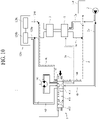
- the third manual steering mechanism 413 allows the working fluid supplied from the manual supply line 4a to be supplied to the steering cylinder 120. As illustrated in FIG. 10 , as the manual steering valve 41 moves, the third manual steering mechanism 413 may be connected to each of the manual supply line 4a, the manual discharge line 4b, the first manual steering line 4c, the second manual steering line 4d, and the hydraulic motor 150. In this case, the third manual steering mechanism 413 may connect the manual supply line 4a and the hydraulic motor 150 and, simultaneously, connect the hydraulic motor 150 and the second manual steering line 4d. That is, the third manual steering mechanism 413 may connect the manual supply line 4a and the second manual steering line 4d.
- the third manual steering mechanism 413 may connect the first manual steering line 4c and the manual discharge line 4b. Therefore, the third manual steering mechanism 413 may cause the working fluid to pass so that the working fluid flows from the manual supply line 4a to the second manual steering line 4d and may cause the working fluid to pass so that the working fluid flows from the first manual steering line 4c to the manual discharge line 4b. Accordingly, since the working fluid is discharged from the first hydraulic chamber 120a while the second hydraulic chamber 120b is being filled with the working fluid, the steering cylinder 120 may change the traveling direction to the second direction. The working fluid discharged from the first hydraulic chamber 120a may be discharged to the external device 140 through the external discharge line 6 via the first manual steering line 4c, the third manual steering mechanism 413, and the manual discharge line 4b.
- the third manual steering mechanism 413 may be connected to each of the manual supply line 4a, the manual discharge line 4b, the first manual steering line 4c, the second manual steering line 4d, the hydraulic motor 150, and the automatic blocking control line 5a.
- the third manual steering mechanism 413 may be implemented to connect the manual supply line 4a, the hydraulic motor 150, and the automatic blocking control line 5a. Therefore, when the manual steering is performed, a portion of the working fluid supplied from the steering pump 2 to the third manual steering mechanism 413 may be branched and supplied to the automatic blocking control line 5a and then may be used in controlling operation of the automatic blocking unit 5 through the automatic blocking control line 5a. In this case, due to the working fluid supplied through the automatic blocking control line 5a, the automatic blocking unit 5 may be operated to block the working fluid for the automatic steering from being supplied to the steering cylinder 120.
- a manual steering elastic member may be coupled to both sides of the manual steering valve 41.
- the manual steering elastic members may elastically press both sides of the manual steering valve 41. Accordingly, when the manual steering is not performed, the manual steering valve 41 may be disposed at a position where the first manual steering mechanism 411 is connected to each of the manual supply line 4a, the manual discharge line 4b, the first manual steering line 4c, the second manual steering line 4d, and the hydraulic motor 150.
- the hydraulic steering device 1 for an agricultural vehicle may include the automatic blocking unit 5.
- the automatic blocking unit 5 selectively blocks the working fluid for the automatic steering from being supplied to the steering cylinder 120 according to whether the manual steering is performed.
- the automatic blocking unit 5 may be connected to each of the manual steering unit 4 and the automatic steering unit 3. Accordingly, the automatic blocking unit 5 may use the working fluid supplied from the steering pump 2 to the manual steering unit 4 to selectively block the working fluid for the automatic steering from being supplied to the steering cylinder 120.
- the automatic blocking unit 5 may be connected to the manual steering unit 4 through the automatic blocking control line 5a. Therefore, the automatic blocking unit 5 may, according to a hydraulic pressure of the working fluid flowing along the automatic blocking control line 5a, selectively block passage of the working fluid for the automatic blocking.
- the automatic blocking unit 5 may cause the working fluid for the automatic steering to pass so that the working fluid for the automatic steering is supplied to the steering cylinder 120.
- the hydraulic pressure of the working fluid flowing along the automatic blocking control line 5a may not be high enough to change an operational state of the automatic blocking unit 5 disposed at a position where the automatic blocking unit 5 causes the working fluid for the automatic steering to pass.
- the automatic blocking unit 5 may be operated to be disposed at a position where the automatic blocking unit 5 blocks passage of the working fluid for the automatic steering. Therefore, since the working fluid supplied by the steering pump 2 is not able to pass through the automatic blocking unit 5, the working fluid supplied by the steering pump 2 is supplied to the manual steering unit 4 so as to be used in the manual steering.
- the hydraulic steering device 1 for an agricultural vehicle according to the present invention may be implemented so that, even when the automatic steering unit 3 is not operated to block passage of the working fluid for the automatic steering when the manual steering is performed, the automatic blocking unit 5 blocks passage of the working fluid for the automatic steering by using the hydraulic pressure of the working fluid flowing along the automatic blocking control line 5a. Therefore, since the hydraulic steering device 1 for an agricultural vehicle according to the present invention is able to change to the manual steering just by manipulation of the steering wheel without control of the automatic steering unit 3 by the controller 130 (see FIG. 2 ), an ease of operation for changing to the manual steering may be improved.
- the working fluid for the automatic steering may flow along the automatic supply line 3a at an inlet side of the automatic steering unit 3.
- the working fluid for the automatic steering may also flow along the first steering line 120d or the second steering line 120e at an outlet side of the automatic steering unit 3.
- the automatic blocking unit 5 may be implemented according to various embodiments according to an arrangement relationship, an operational relationship, the number of valves, and the like. Embodiments of the automatic blocking unit 5 will be sequentially described with reference to the accompanying drawings.
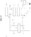
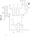
- the automatic blocking unit 5 may be implemented mainly according to an embodiment in which the automatic blocking unit 5 is disposed at a front end of the automatic steering unit 3 as illustrated in FIGS. 3 , 4 , and 11 to 16 (hereinafter referred to as "front end arrangement embodiment") and an embodiment in which the automatic blocking unit 5 is disposed at a rear end of the automatic steering unit 3 as illustrated in FIGS. 17 to 21 (hereinafter referred to as "rear end arrangement embodiment").
- the automatic blocking unit 5 is disposed between the steering pump 2 and the automatic steering unit 3.
- the automatic blocking unit 5 may be installed to be connected to each of the automatic supply line 3a and the automatic discharge line 3b. Accordingly, the automatic blocking unit 5 may selectively cause the working fluid flowing along the automatic supply line 3a to pass so that the working fluid is selectively supplied from the steering pump 2 to the automatic steering unit 3. Simultaneously, the automatic blocking unit 5 may selectively cause the working fluid flowing along the automatic discharge line 3b to pass so that the working fluid is selectively discharged from the automatic steering unit 3 to the external discharge line 6. That is, the automatic blocking unit 5 is disposed to selectively cause the working fluid supplied from the steering pump 2 and the working fluid discharged from the automatic steering unit 3 to pass according to whether the manual steering is performed.
- the automatic blocking unit 5 may cause the working fluid flowing along the automatic supply line 3a to pass so that the working fluid is supplied from the steering pump 2 to the automatic steering unit 3 and, simultaneously, cause the working fluid flowing along the automatic discharge line 3b to pass so that the working fluid is discharged from the automatic steering unit 3 to the external discharge line 6.
- the working fluid flowing along the automatic discharge line 3b may have been discharged from the steering cylinder 120 and then discharged from the automatic steering unit 3.
- the automatic blocking unit 5 may block passage of the working fluid flowing along the automatic supply line 3a so that the working fluid is not able to be supplied from the steering pump 2 to the automatic steering unit 3 and, simultaneously, block passage of the working fluid flowing along the automatic discharge line 3b so that the working fluid is not able to be discharged from the automatic steering unit 3 to the external discharge line 6.
- the working fluid flowing along the automatic discharge line 3b may have been discharged from the steering cylinder 120 and then discharged from the automatic steering unit 3.
- the automatic blocking unit 5 blocks passage of the working fluid flowing along each of the automatic supply line 3a and the automatic discharge line 3b, the working fluid supplied from the manual steering unit 4 to the steering cylinder 120 and the working fluid discharged from the steering cylinder 120 to the manual steering unit 4 are not able to pass through the automatic blocking unit 5. Accordingly, when, as the manual steering is performed, a portion of the working fluid flowing between the manual steering unit 4 and the steering cylinder 120 passes through the automatic steering unit 3, the automatic blocking unit 5 may block passage of the working fluid discharged from the automatic steering unit 3.
- the automatic blocking unit 5 is disposed between the automatic steering unit 3 and the steering cylinder 120.
- the automatic steering unit may be installed to be connected to each of the first steering line 120d and the second steering line 120e. Accordingly, the automatic blocking unit 5 may selectively cause the working fluid flowing along each of the first steering line 120d and the second steering line 120e to pass so that the working fluid is selectively supplied from the automatic steering unit 3 to the steering cylinder 120 and selectively discharged from the steering cylinder 120 to the automatic steering unit 3, simultaneously. That is, the automatic blocking unit 5 is disposed to selectively cause the working fluid supplied from the automatic steering unit 3 and the working fluid discharged from the steering cylinder 120 to pass according to whether the manual steering is performed.
- the automatic blocking unit 5 may cause the working fluid flowing along each of the first steering line 120d and the second steering line 120e to pass so that the working fluid is supplied from the automatic steering unit 3 to the steering cylinder 120 and discharged from the steering cylinder 120 to the automatic steering unit 3, simultaneously.
- the automatic blocking unit 5 may block passage of the working fluid flowing along each of the first steering line 120d and the second steering line 120e so that the working fluid is not able to be supplied from the automatic steering unit 3 to the steering cylinder 120 and not able to be discharged from the steering cylinder 120 to the automatic steering unit 3, simultaneously.
- the first manual steering line 4c and the second manual steering line 4d may be connected to the first steering line 120d and the second steering line 120e, respectively, between the automatic blocking unit 5 and the steering cylinder 120.
- the automatic blocking unit 5 may, when the manual steering is performed, block the working fluid flowing between the manual steering unit 4 and the steering cylinder 120 from passing toward the automatic steering unit 3.
- an automatic blocking unit 5 may include a first blocking valve 51 and a second blocking valve 52.
- the first blocking valve 51 selectively blocks the working fluid for the automatic steering from being supplied to the steering cylinder 120 according to the hydraulic pressure of the working fluid flowing along the automatic blocking control line 5a.
- the hydraulic pressure of the working fluid flowing along the automatic blocking control line 5a may vary according to whether the manual steering is performed.
- the first blocking valve 51 may move between a first automatic position and a first blocking position according to the hydraulic pressure of the working fluid flowing along the automatic blocking control line 5a. As illustrated in FIG. 11 , when the first blocking valve 51 is disposed at the first automatic position, the first blocking valve 51 may allow the working fluid for the automatic steering to be supplied to the steering cylinder 120. As illustrated in FIG. 12 , when the first blocking valve 51 is disposed at the first blocking position, the first blocking valve 51 may block the working fluid for the automatic steering from being supplied to the steering cylinder 120.
- the first blocking valve 51 may be connected to the automatic blocking control line 5a.
- the automatic blocking control line 5a is connected to the manual steering unit 4.
- the automatic blocking control line 5a may be connected to the manual steering valve 41.
- a first automatic blocking line 51a may be connected to one side of the first blocking valve 51.
- the automatic blocking control line 5a may have one side connected to the manual steering unit 4 and the other side connected to the first automatic blocking line 51a.
- the first automatic blocking line 51a may have one side connected to the automatic blocking control line 5a and the other side connected to the one side of the first blocking valve 51.
- the working fluid flowing along the automatic blocking control line 5a may, after being supplied to the first automatic blocking line 51a, flow along the first automatic blocking line 51a and press the one side of the first blocking valve 51.
- the working fluid flowing along the first automatic blocking line 51a may press the one side of the first blocking valve 51 in a direction in which the first blocking valve 51 moves from the first automatic position to the first blocking position. Therefore, when, as the manual steering is performed, the hydraulic pressure of the working fluid flowing along the automatic blocking control line 5a and the first automatic blocking line 51a increases, the first blocking valve 51 may move from the first automatic position to the first blocking position and thus block passage of the working fluid for the automatic steering.
- the working fluid supplied from the steering pump 2 may be supplied to the manual steering unit 4 and used in the manual steering.
- the working fluid discharged from the steering cylinder 120 in a process in which the manual steering is performed may be induced to be discharged to the manual steering unit 4.
- the working fluid supplied from the manual steering unit 4 to the steering cylinder 120 in the process in which the manual steering is performed may be supplied to the steering cylinder 120 without leaking through the first blocking valve 51.
- the first blocking valve 51 may be installed to be connected to the automatic supply line 3a. As illustrated in FIG. 11 , when the first blocking valve 51 is disposed at the first automatic position, the working fluid supplied from the steering pump 2 may pass through the first blocking valve 51 and be supplied to the automatic steering unit 3. The working fluid supplied to the automatic steering unit 3 may be supplied to the steering cylinder 120 in a direction in which the automatic steering is performed. As illustrated in FIG. 12 , when the first blocking valve 51 is disposed at the first blocking position, the working fluid supplied from the steering pump 2 is not able to pass through the first blocking valve 51 and thus is not able to be supplied to the automatic steering unit 3. Accordingly, the working fluid supplied from the steering pump 2 may be supplied to the manual steering unit 4 and then be supplied to the steering cylinder 120 in a direction in which the manual steering is performed.
- the first blocking valve 51 may include a first passing mechanism 511 and a first blocking mechanism 512.
- the first passing mechanism 511 allows passage of a working fluid. As illustrated in FIG. 11 , when the first blocking valve 51 is disposed at the first automatic position, the first passing mechanism 511 may be connected to the automatic supply line 3a. Accordingly, the working fluid supplied from the steering pump 2 may pass through the first blocking valve 51 and be supplied to the automatic steering unit 3.
- the first blocking mechanism 512 blocks passage of a working fluid. As illustrated in FIG. 12 , when the first blocking valve 51 is disposed at the first blocking position, the first blocking mechanism 512 may be connected to the automatic supply line 3a. Accordingly, the working fluid supplied from the steering pump 2 is not able to pass through the first blocking valve 51 and thus is not able to be supplied to the automatic steering unit 3.
- the second blocking valve 52 selectively blocks passage of the working fluid discharged from the steering cylinder 120 according to the hydraulic pressure of the working fluid flowing along the automatic blocking control line 5a.
- the second blocking valve 52 may move between a second automatic position and a second blocking position according to the hydraulic pressure of the working fluid flowing along the automatic blocking control line 5a. As illustrated in FIG. 11 , when the second blocking valve 52 is disposed at the second automatic position, the second blocking valve 52 may allow passage of the working fluid discharged from the steering cylinder 120. As illustrated in FIG. 12 , when the second blocking valve 52 is disposed at the second blocking position, the second blocking valve 52 may block passage of the working fluid discharged from the steering cylinder 120.
- the second blocking valve 52 may be connected to the automatic blocking control line 5a.
- a second automatic blocking line 52a may be connected to one side of the second blocking valve 52.
- the automatic blocking control line 5a may have one side connected to the manual steering unit 4 and the other side connected to the second automatic blocking line 52a.
- the second automatic blocking line 52a may have one side connected to the automatic blocking control line 5a and the other side connected to the one side of the second blocking valve 52. Accordingly, the working fluid flowing along the automatic blocking control line 5a may, after being supplied to the second automatic blocking line 52a, flow along the second automatic blocking line 52a and press the one side of the second blocking valve 52.
- the working fluid flowing along the second automatic blocking line 52a may press the one side of the second blocking valve 52 in a direction in which the second blocking valve 52 moves from the second automatic position to the second blocking position. Therefore, when, as the manual steering is performed, the hydraulic pressure of the working fluid flowing along the automatic blocking control line 5a and the second automatic blocking line 52a increases, the second blocking valve 52 may move from the second automatic position to the second blocking position and thus block passage of the working fluid discharged from the steering cylinder 120. Accordingly, the working fluid discharged from the steering cylinder 120 in the process in which the manual steering is performed may be induced to be discharged to the manual steering unit 4. Also, the working fluid supplied from the manual steering unit 4 to the steering cylinder 120 in the process in which the manual steering is performed may be supplied to the steering cylinder 120 without leaking through the second blocking valve 52.
- the second blocking valve 52 may be installed to be connected to the automatic discharge line 3b. As illustrated in FIG. 11 , when the second blocking valve 52 is disposed at the second automatic position, the working fluid discharged from the steering cylinder 120 may br, after passing through the second blocking valve 52 and being discharged to the external discharge line 6, discharged to the external device 140 through the external discharge line 6. As illustrated in FIG. 12 , when the second blocking valve 52 is disposed at the second blocking position, the working fluid discharged from the steering cylinder 120 is not able to pass through the second blocking valve 52 and thus is not able to be discharged to the external discharge line 6 through the automatic discharge line 3b.
- the second blocking valve 52 may include a second passing mechanism 521 and a second blocking mechanism 522.
- the second passing mechanism 521 allows passage of a working fluid. As illustrated in FIG. 11 , when the second blocking valve 52 is disposed at the second automatic position, the second passing mechanism 521 may be connected to the automatic discharge line 3b. Accordingly, the working fluid discharged from the steering cylinder 120 may be, after passing through the second blocking valve 52 and being discharged to the external discharge line 6, discharged to the external device 140 through the external discharge line 6. A portion of the working fluid passing through the second blocking valve 52 and being discharged to the external discharge line 6 may, after being supplied to the manual steering unit 4 through the external discharge line 6, flow along the automatic blocking control line 5a, the first automatic blocking line 51a, and the second automatic blocking line 52a and press the one side of the first blocking valve 51 and the one side of the second blocking valve 52.
- the hydraulic pressure of the working fluid on each of the one side of the first blocking valve 51 and the one side of the second blocking valve 52 may not be high enough to cause the first blocking valve 51 and the second blocking valve 52 to move to the first blocking position and the second blocking position, respectively.
- the second blocking mechanism 522 blocks passage of a working fluid. As illustrated in FIG. 12 , when the second blocking valve 52 is disposed at the second blocking position, the second blocking mechanism 522 may be connected to the automatic discharge line 3b. Accordingly, the working fluid discharged from the steering cylinder 120 is not able to pass through the second blocking valve 52 and thus is not able to be discharged to the external discharge line 6 through the automatic discharge line 3b.
- the automatic blocking unit 5 may include a first elastic member 53 and a second elastic member 54.
- the first elastic member 53 is coupled to the other side of the first blocking valve 51.
- the first elastic member 53 may press the other side of the first blocking valve 51 in a direction in which the first blocking valve 51 moves from the first blocking position to the first automatic position. Accordingly, the first blocking valve 51 may have one side pressed due to the hydraulic pressure of the working fluid flowing along the first automatic blocking line 51a and the other side pressed due to an elastic force of the first elastic member 53. Therefore, using a difference between the hydraulic pressure of the working fluid flowing along the first automatic blocking line 51a and the elastic force of the first elastic member 53, the first blocking valve 51 may move between the first automatic position and the first blocking position.
- the first blocking valve 51 may move between the first automatic position and the first blocking position according to the hydraulic pressure of the working fluid flowing along the first automatic blocking line 51a.
- the hydraulic pressure of the working fluid flowing along the first automatic blocking line 51a and the hydraulic pressure of the working fluid flowing along the automatic blocking control line 5a may be equal to each other.
- the hydraulic pressure of the working fluid flowing along the first automatic blocking line 51a may be decreased to be less than the elastic force of the first elastic member 53. Accordingly, when the manual steering is not performed, the first blocking valve 51 may move to the first automatic position. Therefore, the working fluid supplied by the steering pump 2 may pass through the first blocking valve 51. Even when the automatic steering is performed in the state in which the manual steering is not performed, the first blocking valve 51 may move to the first automatic position.
- the hydraulic pressure of the working fluid flowing along the first automatic blocking line 51a may be increased to be greater than the elastic force of the first elastic member 53. Accordingly, when the manual steering is performed, the first blocking valve 51 may move to the first blocking position. Therefore, the working fluid supplied by the steering pump 2 is not able to pass through the first blocking valve 51.
- the first elastic member 53 may be formed to have an elastic force greater than the hydraulic pressure of the working fluid flowing along the first automatic blocking line 51a when the manual steering is not performed and have an elastic force less than the hydraulic pressure of the working fluid flowing along the first automatic blocking line 51a when the manual steering is performed.
- the second elastic member 54 is coupled to the other side of the second blocking valve 52.
- the second elastic member 54 may press the other side of the second blocking valve 52 in a direction in which the second blocking valve 52 moves from the second blocking position to the second automatic position. Accordingly, the second blocking valve 52 may have one side pressed due to the hydraulic pressure of the working fluid flowing along the second automatic blocking line 52a and the other side pressed due to an elastic force of the second elastic member 54. Therefore, using a difference between the hydraulic pressure of the working fluid flowing along the second automatic blocking line 52a and the elastic force of the second elastic member 54, the second blocking valve 52 may move between the second automatic position and the second blocking position.
- the second blocking valve 52 may move between the second automatic position and the second blocking position according to the hydraulic pressure of the working fluid flowing along the second automatic blocking line 52a.
- the hydraulic pressure of the working fluid flowing along the second automatic blocking line 52a and the hydraulic pressure of the working fluid flowing along the automatic blocking control line 5a may be equal to each other.
- the hydraulic pressure of the working fluid flowing along the second automatic blocking line 52a may be decreased to be less than the elastic force of the second elastic member 54. Accordingly, when the manual steering is not performed, the second blocking valve 52 may move to the second automatic position. Therefore, the working fluid discharged from the steering cylinder 120 may pass through the second blocking valve 52. Even when the automatic steering is performed in the state in which the manual steering is not performed, the second blocking valve 52 may move to the second automatic position.
- the hydraulic pressure of the working fluid flowing along the second automatic blocking line 52a may be increased to be greater than the elastic force of the second elastic member 54. Accordingly, when the manual steering is performed, the second blocking valve 52 may move to the second blocking position. Therefore, the working fluid discharged from the steering cylinder 120 is not able to pass through the second blocking valve 52.
- the second elastic member 54 may be formed to have an elastic force greater than the hydraulic pressure of the working fluid flowing along the second automatic blocking line 52a when the manual steering is not performed and have an elastic force less than the hydraulic pressure of the working fluid flowing along the second automatic blocking line 52a when the manual steering is performed.
- an automatic blocking unit 5 according to a second embodiment may be implemented to substantially match the automatic blocking unit 5 according to the first embodiment illustrated in FIGS. 11 and 12 . Therefore, the automatic blocking unit 5 according to the second embodiment will be described focusing on differences from the first embodiment.
- the automatic blocking unit 5 may further include a first automatic maintaining line 51b and a second automatic maintaining line 52b.
- the first automatic maintaining line 51b is connected to the other side of the first blocking valve 51. Since the first automatic maintaining line 51b is connected to the other side of the first blocking valve 51, a working fluid flowing along the first automatic maintaining line 51b may press the other side of the first blocking valve 51. Accordingly, a pressing force, which is the sum of the elastic force of the first elastic member 53 and the hydraulic pressure of the working fluid flowing along the first automatic maintaining line 51b, may press the other side of the first blocking valve 51 in a direction in which the first blocking valve 51 moves from the first blocking position to the first automatic position.
- the first automatic maintaining line 51b may be connected to each of the external discharge line 6 and the other side of the first blocking valve 51. Accordingly, the working fluid flowing along the first automatic maintaining line 51b is a branched portion of the working fluid flowing to be discharged to the external device 140 along the external discharge line 6.
- the first elastic member 53 in the second embodiment in which the first automatic maintaining line 51b is included may be implemented to have a smaller elastic force than the first elastic member 53 in the first embodiment in which the first automatic maintaining line 51b is not included. Therefore, in the second embodiment in which the first automatic maintaining line 51b is included, material costs for the first elastic member 53 may be reduced as compared to the first embodiment in which the first automatic maintaining line 51b is not included.
- the hydraulic pressure of the working fluid flowing along the first automatic blocking line 51a becomes greater than the pressing force which is the sum of the elastic force of the first elastic member 53 and the hydraulic pressure of the working fluid flowing along the first automatic maintaining line 51b. Accordingly, the first blocking valve 51 may move to the first blocking position and thus block supply of the working fluid from the steering pump 2 to the automatic steering unit 3.
- the second automatic maintaining line 52b is connected to the other side of the second blocking valve 52. Since the second automatic maintaining line 52b is connected to the other side of the second blocking valve 52, a working fluid flowing along the second automatic maintaining line 52b may press the other side of the second blocking valve 52. Accordingly, a pressing force, which is the sum of the elastic force of the second elastic member 54 and the hydraulic pressure of the working fluid flowing along the second automatic maintaining line 52b, may press the other side of the second blocking valve 52 in a direction in which the second blocking valve 52 moves from the second blocking position to the second automatic position.
- the second automatic maintaining line 52b may be connected to each of the external discharge line 6 and the other side of the second blocking valve 52. Accordingly, the working fluid flowing along the second automatic maintaining line 52b is a branched portion of the working fluid flowing to be discharged to the external device 140 along the external discharge line 6.
- the second elastic member 54 in the second embodiment in which the second automatic maintaining line 52b is included may be implemented to have a smaller elastic force than the second elastic member 54 in the first embodiment in which the second automatic maintaining line 52b is not included. Therefore, in the second embodiment in which the second automatic maintaining line 52b is included, material costs for the second elastic member 54 may be reduced as compared to the first embodiment in which the second automatic maintaining line 52b is not included.
- the hydraulic pressure of the working fluid flowing along the second automatic blocking line 52a becomes greater than the pressing force which is the sum of the elastic force of the second elastic member 54 and the hydraulic pressure of the working fluid flowing along the second automatic maintaining line 52b. Accordingly, the second blocking valve 52 may move to the second blocking position and thus block the working fluid discharged from the steering cylinder 120 from being discharged to the external discharge line 6 through the automatic discharge line 3b.
- an automatic blocking unit 5 according to a third embodiment may be implemented to substantially match the automatic blocking unit 5 according to the first embodiment illustrated in FIGS. 11 and 12 . Therefore, the automatic blocking unit 5 according to the third embodiment will be described focusing on differences from the first embodiment.
- the automatic blocking unit 5 according to the third embodiment differs from the first embodiment in that the first blocking valve 51 (see FIG. 11 ) and the second blocking valve 52 (see FIG. 11 ) in the first embodiment are replaced with a single blocking valve 55.
- the blocking valve 55 may move between an automatic position and a blocking position according to a hydraulic pressure of a working fluid flowing along the automatic blocking control line 5a.
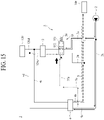
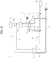
- the blocking valve 55 When the blocking valve 55 is disposed at the automatic position as illustrated in FIG. 14 , the blocking valve 55 may, while allowing supply of a working fluid for the automatic steering to the steering cylinder 120, allow passage of a working fluid discharged from the steering cylinder 120.
- the blocking valve 55 When the blocking valve 55 is disposed at the blocking position as illustrated in FIG. 15 , the blocking valve 55 may, while blocking supply of the working fluid for the automatic steering to the steering cylinder 120, block passage of the working fluid discharged from the steering cylinder 120.
- the blocking valve 55 may be connected to the automatic blocking control line 5a.
- An automatic blocking line 55a may be connected to one side of the blocking valve 55.
- the automatic blocking control line 5a may have one side connected to the manual steering unit 4 and the other side connected to the automatic blocking line 55a.
- the automatic blocking line 55a may have one side connected to the automatic blocking control line 5a and the other side connected to the one side of the blocking valve 55. Accordingly, the working fluid flowing along the automatic blocking control line 5a may, after being supplied to the automatic blocking line 55a, flow along the automatic blocking line 55a and press the one side of the blocking valve 55. In this case, the working fluid flowing along the automatic blocking line 55a may press the one side of the blocking valve 55 in a direction in which the blocking valve 55 moves from the automatic position to the blocking position.
- the blocking valve 55 may be installed to be connected to each of the automatic supply line 3a and the automatic discharge line 3b.
- the blocking valve 55 When the blocking valve 55 is disposed at the automatic position as illustrated in FIG. 14 , the working fluid supplied from the steering pump 2 may pass through the blocking valve 55 and be supplied to the automatic steering unit 3. In this case, the working fluid discharged from the steering cylinder 120 may pass through the blocking valve 55 and be discharged to the external discharge line 6.
- the blocking valve 55 is disposed at the blocking position as illustrated in FIG. 15 , the working fluid supplied from the steering pump 2 is not able to pass through the blocking valve 55 and thus is not able to be supplied to the automatic steering unit 3. In this case, the working fluid discharged from the steering cylinder 120 is not able to pass through the blocking valve 55 and thus is not able to be supplied to the external discharge line 6 through the automatic discharge line 3b.
- the blocking valve 55 may include a passing mechanism 551 and a blocking mechanism 552.
- the passing mechanism 551 allows passage of a working fluid.
- the passing mechanism 551 may be connected to each of the automatic supply line 3a and the automatic discharge line 3b. Accordingly, the working fluid supplied from the steering pump 2 may pass through the blocking valve 55 and be supplied to the automatic steering unit 3.
- the working fluid discharged from the steering cylinder 120 may be, after passing through the blocking valve 55 and being supplied to the external discharge line 6, discharged to the external device 140 through the external discharge line 6.
- the blocking mechanism 552 blocks passage of a working fluid.
- the blocking valve 55 When the blocking valve 55 is disposed at the blocking position as illustrated in FIG. 15 , the blocking mechanism 552 may be connected to each of the automatic supply line 3a and the automatic discharge line 3b. Accordingly, the working fluid supplied from the steering pump 2 is not able to pass through the blocking valve 55 and thus is not able to be supplied to the automatic steering unit 3. The working fluid discharged from the steering cylinder 120 is not able to pass through the blocking valve 55 and thus is not able to be discharged to the external discharge line 6 through the automatic discharge line 3b.
- the automatic blocking unit 5 may include an elastic member 56.
- the elastic member 56 is coupled to the other side of the blocking valve 55.
- the elastic member 56 may press the other side of the blocking valve 55 in a direction in which the blocking valve 55 moves from the blocking position to the automatic position. Accordingly, the blocking valve 55 may have one side pressed due to the hydraulic pressure of the working fluid flowing along the automatic blocking line 55a and the other side pressed due to an elastic force of the elastic member 56. Therefore, using a difference between the hydraulic pressure of the working fluid flowing along the automatic blocking line 55a and the elastic force of the elastic member 56, the blocking valve 55 may move between the automatic position and the blocking position.
- the blocking valve 55 may move between the automatic position and the blocking position according to the hydraulic pressure of the working fluid flowing along the automatic blocking line 55a.
- the hydraulic pressure of the working fluid flowing along the automatic blocking line 55a and the hydraulic pressure of the working fluid flowing along the automatic blocking control line 5a may be equal to each other.
- the hydraulic pressure of the working fluid flowing along the automatic blocking line 55a may be decreased to be less than the elastic force of the elastic member 56. Accordingly, when the manual steering is not performed, the blocking valve 55 may move to the automatic position.
- the hydraulic pressure of the working fluid flowing along the automatic blocking line 55a may be increased to be greater than the elastic force of the elastic member 56. Accordingly, when the manual steering is performed, the blocking valve 55 may move to the blocking position.
- the elastic member 56 may be formed to have an elastic force greater than the hydraulic pressure of the working fluid flowing along the automatic blocking line 55a when the manual steering is not performed and have an elastic force less than the hydraulic pressure of the working fluid flowing along the automatic blocking line 55a when the manual steering is performed.
- an automatic blocking unit 5 according to a fourth embodiment may be implemented to substantially match the automatic blocking unit 5 according to the third embodiment illustrated in FIGS. 14 and 15 . Therefore, the automatic blocking unit 5 according to the fourth embodiment will be described focusing on differences from the third embodiment.
- the automatic blocking unit 5 may further include an automatic maintaining line 55b.
- the automatic maintaining line 55b is connected to the other side of the blocking valve 55. Since the automatic maintaining line 55b is connected to the other side of the blocking valve 55, a working fluid flowing along the automatic maintaining line 55b may press the other side of the blocking valve 55. Accordingly, a pressing force, which is the sum of the elastic force of the elastic member 56 and the hydraulic pressure of the working fluid flowing along the automatic maintaining line 55b, may press the other side of the blocking valve 55 in a direction in which the blocking valve 55 moves from the blocking position to the automatic position.
- the automatic maintaining line 55b may be connected to each of the external discharge line 6 and the other side of the blocking valve 55. Accordingly, the working fluid flowing along the automatic maintaining line 55b is a branched portion of the working fluid flowing to be discharged to the external device 140 along the external discharge line 6.
- the elastic member 56 in the fourth embodiment in which the automatic maintaining line 55b is included may be implemented to have a smaller elastic force than the elastic member 56 in the third embodiment in which the automatic maintaining line 55b is not included. Therefore, in the fourth embodiment in which the automatic maintaining line 55b is included, material costs for the elastic member 56 may be reduced as compared to the third embodiment in which the automatic maintaining line 55b is not included.
- the hydraulic pressure of the working fluid flowing along the automatic blocking line 55a becomes greater than the pressing force which is the sum of the elastic force of the elastic member 56 and the hydraulic pressure of the working fluid flowing along the automatic maintaining line 55b. Accordingly, the blocking valve 55 may move to the blocking position.
- an automatic blocking unit 5 according to a fifth embodiment may be implemented to substantially match the automatic blocking unit 5 according to the first embodiment illustrated in FIGS. 11 and 12 . Therefore, the automatic blocking unit 5 according to the fifth embodiment will be described focusing on differences from the first embodiment.
- the automatic blocking unit 5 according to the fifth embodiment differs from the first embodiment in that, instead of the automatic blocking unit 5 being disposed between the steering pump 2 and the automatic steering unit 3 as in the first embodiment, the automatic blocking unit 5 is disposed between the automatic steering unit 3 and the steering cylinder 120.
- the first blocking valve 51 may be installed to be connected to the first steering line 120d.
- the first blocking valve 51 may move between the first automatic position and the first blocking position according to the hydraulic pressure of the working fluid flowing along the automatic blocking control line 5a.
- the first blocking valve 51 When a working fluid is supplied from the automatic steering unit 3 to the first steering line 120d, the first blocking valve 51 may, when disposed at the first automatic position, allow passage of the working fluid supplied from the automatic steering unit 3. When a working fluid is discharged from the steering cylinder 120 to the first steering line 120d, the first blocking valve 51 may, when disposed at the first automatic position, allow passage of the working fluid discharged from the steering cylinder 120.
- the first blocking valve 51 When a working fluid is supplied from the automatic steering unit 3 to the first steering line 120d, the first blocking valve 51 may, when disposed at the first blocking position, block passage of the working fluid supplied from the automatic steering unit 3. When a working fluid is discharged from the steering cylinder 120 to the first steering line 120d, the first blocking valve 51 may, when disposed at the first blocking position, block passage of the working fluid discharged from the steering cylinder 120.
- the first blocking valve 51 may include the first passing mechanism 511 and the first blocking mechanism 512.
- the first passing mechanism 511 allows passage of a working fluid.
- the first passing mechanism 511 may be connected to the first steering line 120d. Accordingly, the working fluid flowing along the first steering line 120d may pass through the first blocking valve 51.
- the first blocking mechanism 512 blocks passage of a working fluid.
- the first blocking mechanism 512 may be connected to the first steering line 120d. Accordingly, the working fluid flowing along the first steering line 120d is not able to pass through the first blocking valve 51.
- the first blocking valve 51 may have one side pressed due to the hydraulic pressure of the working fluid flowing along the first automatic blocking line 51a and the other side pressed due to the elastic force of the first elastic member 53. Therefore, using the difference between the hydraulic pressure of the working fluid flowing along the first automatic blocking line 51a and the elastic force of the first elastic member 53, the first blocking valve 51 may move between the first automatic position and the first blocking position.
- the first elastic member 53 may be formed to have an elastic force greater than the hydraulic pressure of the working fluid flowing along the first automatic blocking line 51a when the manual steering is not performed and have an elastic force less than the hydraulic pressure of the working fluid flowing along the first automatic blocking line 51a when the manual steering is performed.
- the second blocking valve 52 may be installed to be connected to the second steering line 120e.
- the second blocking valve 52 may move between the second automatic position and the second blocking position according to the hydraulic pressure of the working fluid flowing along the automatic blocking control line 5a.
- the second blocking valve 52 When a working fluid is supplied from the automatic steering unit 3 to the second steering line 120e, the second blocking valve 52 may, when disposed at the second automatic position, allow passage of the working fluid supplied from the automatic steering unit 3. When a working fluid is discharged from the steering cylinder 120 to the second steering line 120e, the second blocking valve 52 may, when disposed at the second automatic position, allow passage of the working fluid discharged from the steering cylinder 120.
- the second blocking valve 52 When a working fluid is supplied from the automatic steering unit 3 to the second steering line 120e, the second blocking valve 52 may, when disposed at the second blocking position, block passage of the working fluid supplied from the automatic steering unit 3. When a working fluid is discharged from the steering cylinder 120 to the second steering line 120e, the second blocking valve 52 may, when disposed at the second blocking position, block passage of the working fluid discharged from the steering cylinder 120.
- the second blocking valve 52 may include the second passing mechanism 521 and the second blocking mechanism 522.
- the second passing mechanism 521 allows passage of a working fluid.
- the second blocking valve 52 When the second blocking valve 52 is disposed at the second automatic position, the second passing mechanism 521 may be connected to the second steering line 120e. Accordingly, the working fluid flowing along the second steering line 120e may pass through the second blocking valve 52.
- the second blocking mechanism 522 blocks passage of a working fluid.
- the second blocking mechanism 522 may be connected to the second steering line 120e. Accordingly, the working fluid flowing along the second steering line 120e is not able to pass through the second blocking valve 52.
- the second blocking valve 52 may have one side pressed due to the hydraulic pressure of the working fluid flowing along the second automatic blocking line 52a and the other side pressed due to the elastic force of the second elastic member 54. Therefore, using the difference between the hydraulic pressure of the working fluid flowing along the second automatic blocking line 52a and the elastic force of the second elastic member 54, the second blocking valve 52 may move between the second automatic position and the second blocking position.
- the second elastic member 54 may be formed to have an elastic force greater than the hydraulic pressure of the working fluid flowing along the second automatic blocking line 52a when the manual steering is not performed and have an elastic force less than the hydraulic pressure of the working fluid flowing along the second automatic blocking line 52a when the manual steering is performed.
- an automatic blocking unit 5 according to a sixth embodiment may be implemented to substantially match the automatic blocking unit 5 according to the fifth embodiment illustrated in FIG. 18 . Therefore, the automatic blocking unit 5 according to the sixth embodiment will be described focusing on differences from the fifth embodiment.
- the automatic blocking unit 5 may further include the first automatic maintaining line 51b and the second automatic maintaining line 52b.
- the first automatic maintaining line 51b is connected to the other side of the first blocking valve 51. Since the first automatic maintaining line 51b is connected to the other side of the first blocking valve 51, a working fluid flowing along the first automatic maintaining line 51b may press the other side of the first blocking valve 51. Accordingly, a pressing force, which is the sum of the elastic force of the first elastic member 53 and the hydraulic pressure of the working fluid flowing along the first automatic maintaining line 51b, may press the other side of the first blocking valve 51 in a direction in which the first blocking valve 51 moves from the first blocking position to the first automatic position.
- the first automatic maintaining line 51b may be connected to each of the external discharge line 6 and the other side of the first blocking valve 51. Accordingly, the working fluid flowing along the first automatic maintaining line 51b is a branched portion of the working fluid flowing to be discharged to the external device 140 along the external discharge line 6.
- the first elastic member 53 in the sixth embodiment in which the first automatic maintaining line 51b is included may be implemented to have a smaller elastic force than the first elastic member 53 in the fifth embodiment in which the first automatic maintaining line 51b is not included. Therefore, in the sixth embodiment in which the first automatic maintaining line 51b is included, material costs for the first elastic member 53 may be reduced as compared to the fifth embodiment in which the first automatic maintaining line 51b is not included.
- the hydraulic pressure of the working fluid flowing along the first automatic blocking line 51a becomes greater than the pressing force which is the sum of the elastic force of the first elastic member 53 and the hydraulic pressure of the working fluid flowing along the first automatic maintaining line 51b. Accordingly, the first blocking valve 51 may move to the first blocking position.
- the second automatic maintaining line 52b is connected to the other side of the second blocking valve 52. Since the second automatic maintaining line 52b is connected to the other side of the second blocking valve 52, a working fluid flowing along the second automatic maintaining line 52b may press the other side of the second blocking valve 52. Accordingly, a pressing force, which is the sum of the elastic force of the second elastic member 54 and the hydraulic pressure of the working fluid flowing along the second automatic maintaining line 52b, may press the other side of the second blocking valve 52 in a direction in which the second blocking valve 52 moves from the second blocking position to the second automatic position.
- the second automatic maintaining line 52b may be connected to each of the external discharge line 6 and the other side of the second blocking valve 52. Accordingly, the working fluid flowing along the second automatic maintaining line 52b is a branched portion of the working fluid flowing to be discharged to the external device 140 along the external discharge line 6.
- the second elastic member 54 in the sixth embodiment in which the second automatic maintaining line 52b is included may be implemented to have a smaller elastic force than the second elastic member 54 in the fifth embodiment in which the second automatic maintaining line 52b is not included. Therefore, in the sixth embodiment in which the second automatic maintaining line 52b is included, material costs for the second elastic member 54 may be reduced as compared to the fifth embodiment in which the second automatic maintaining line 52b is not included.
- the hydraulic pressure of the working fluid flowing along the second automatic blocking line 52a becomes greater than the pressing force which is the sum of the elastic force of the second elastic member 54 and the hydraulic pressure of the working fluid flowing along the second automatic maintaining line 52b. Accordingly, the second blocking valve 52 may move to the second blocking position.
- an automatic blocking unit 5 according to a seventh embodiment may be implemented to substantially match the automatic blocking unit 5 according to the fifth embodiment illustrated in FIG. 18 . Therefore, the automatic blocking unit 5 according to the seventh embodiment will be described focusing on differences from the fifth embodiment.
- the automatic blocking unit 5 according to the seventh embodiment differs from the fifth embodiment in that the first blocking valve 51 (see FIG. 18 ) and the second blocking valve 52 (see FIG. 18 ) in the fifth embodiment are replaced with a single blocking valve 55.
- the blocking valve 55 may be installed to be connected to each of the first steering line 120d and the second steering line 120e.
- the blocking valve 55 may move between the automatic position and the blocking position according to the hydraulic pressure of the working fluid flowing along the automatic blocking control line 5a.
- the blocking valve 55 When the blocking valve 55 is disposed at the automatic position, the blocking valve 55 may, while allowing passage of the working fluid supplied from the automatic steering unit 3, allow passage of the working fluid discharged from the steering cylinder 120.
- the blocking valve 55 When the blocking valve 55 is disposed at the blocking position, the blocking valve 55 may, while blocking passage of the working fluid supplied from the automatic steering unit 3, block passage of the working fluid discharged from the steering cylinder 120.
- the blocking valve 55 may include the passing mechanism 551 and the blocking mechanism 552.
- the passing mechanism 551 allows passage of a working fluid.
- the passing mechanism 551 may be connected to each of the first steering line 120d and the second steering line 120e. Accordingly, the working fluid flowing along the first steering line 120d and the working fluid flowing along the second steering line 120e may pass through the blocking valve 55.
- the blocking mechanism 552 blocks passage of a working fluid.
- the blocking mechanism 552 may be connected to each of the first steering line 120d and the second steering line 120e. Accordingly, the working fluid flowing along the first steering line 120d and the working fluid flowing along the second steering line 120e are not able to pass through the blocking valve 55.
- the blocking valve 55 may have one side pressed due to the hydraulic pressure of the working fluid flowing along the automatic blocking line 55a and the other side pressed due to the elastic force of the elastic member 56. Therefore, using the difference between the hydraulic pressure of the working fluid flowing along the automatic blocking line 55a and the elastic force of the elastic member 56, the blocking valve 55 may move between the automatic position and the blocking position.
- the elastic member 56 may be formed to have an elastic force greater than the hydraulic pressure of the working fluid flowing along the automatic blocking line 55a when the manual steering is not performed and have an elastic force less than the hydraulic pressure of the working fluid flowing along the automatic blocking line 55a when the manual steering is performed.
- an automatic blocking unit 5 according to an eighth embodiment may be implemented to substantially match the automatic blocking unit 5 according to the seventh embodiment illustrated in FIG. 20 . Therefore, the automatic blocking unit 5 according to the eighth embodiment will be described focusing on differences from the seventh embodiment.
- the automatic blocking unit 5 may further include the automatic maintaining line 55b.
- the automatic maintaining line 55b is connected to the other side of the blocking valve 55. Since the automatic maintaining line 55b is connected to the other side of the blocking valve 55, a working fluid flowing along the automatic maintaining line 55b may press the other side of the blocking valve 55. Accordingly, a pressing force, which is the sum of the elastic force of the elastic member 56 and the hydraulic pressure of the working fluid flowing along the automatic maintaining line 55b, may press the other side of the blocking valve 55 in a direction in which the blocking valve 55 moves from the blocking position to the automatic position.
- the automatic maintaining line 55b may be connected to each of the external discharge line 6 and the other side of the blocking valve 55. Accordingly, the working fluid flowing along the automatic maintaining line 55b is a branched portion of the working fluid flowing to be discharged to the external device 140 along the external discharge line 6.
- the elastic member 56 in the eighth embodiment in which the automatic maintaining line 55b is included may be implemented to have a smaller elastic force than the elastic member 56 in the seventh embodiment in which the automatic maintaining line 55b is not included. Therefore, in the eighth embodiment in which the automatic maintaining line 55b is included, material costs for the elastic member 56 may be reduced as compared to the seventh embodiment in which the automatic maintaining line 55b is not included.
- the hydraulic pressure of the working fluid flowing along the automatic blocking line 55a becomes greater than the pressing force which is the sum of the elastic force of the elastic member 56 and the hydraulic pressure of the working fluid flowing along the automatic maintaining line 55b. Accordingly, the blocking valve 55 may move to the blocking position.
- the hydraulic steering device 1 for an agricultural vehicle may include a steering priority unit 7.
- the steering priority unit 7 is connected to each of the steering pump 2 and the external discharge line 6.
- the steering priority unit 7 may have one side connected to the steering pump 2 and the other side connected to the external discharge line 6.
- the steering priority unit 7 may be connected to the steering pump 2 through a supply line 7a.
- the supply line 7a may be connected to the pump supply line 2a and may be connected to the steering pump 2 through the pump supply line 2a.
- the steering priority unit 7 may be connected to the external discharge line 6 through a discharge line 7b.
- the steering priority unit 7 may, according to whether any one of the manual steering and the automatic steering is performed, selectively discharge the working fluid supplied from the steering pump 2 to the external discharge line 6. When any one of the manual steering and the automatic steering is performed, the steering priority unit 7 may block the working fluid supplied from the steering pump 2 from being discharged to the external discharge line 6. Accordingly, when the manual steering or the automatic steering is performed, the steering priority unit 7 may be implemented to block the working fluid supplied from the steering pump 2 from being immediately discharged to the external device 140 without passing through the automatic steering unit 3 or the manual steering unit 4. Therefore, the hydraulic steering device 1 for an agricultural vehicle according to the present invention may prevent insufficient supply of a working fluid to the manual steering unit 4 or the automatic steering unit 3 in the process in which the manual steering or the automatic steering is performed.
- the steering priority unit 7 may include a steering priority valve 71.
- the steering priority valve 71 moves between a steering priority position and an external discharge position. As illustrated in FIG. 22 , when the steering priority valve 71 is disposed at the steering priority position, the steering priority valve 71 may block supply of a working fluid from the supply line 7a to the discharge line 7b. Accordingly, the working fluid supplied by the steering pump 2 may be blocked by the steering priority valve 71 so as not to be immediately discharged to the external discharge line 6. This case may be a state in which any one of the manual steering and the automatic steering is performed. As illustrated in FIG. 23 , when the steering priority valve 71 is disposed at the external discharge position, the steering priority valve 71 may allow supply of the working fluid from the supply line 7a to the discharge line 7b.
- the entire working fluid supplied by the steering pump 2 or a portion of the working fluid may be immediately discharged to the external discharge line 6 and then supplied to the external device 140 through the external discharge line 6.
- This case may be a state in which neither of the manual steering and the automatic steering is performed.
- the steering priority valve 71 may move between the steering priority position and the external discharge position according to the hydraulic pressure of the working fluid flowing along the supply line 7a.
- the steering priority valve 71 may include an external discharge mechanism 711 and a steering priority mechanism 712.
- the external discharge mechanism 711 allows passage of a working fluid. As illustrated in FIG. 23 , when the steering priority valve 71 is disposed at the external discharge position, the external discharge mechanism 711 may be connected to each of the supply line 7a and the discharge line 7b. Accordingly, the working fluid supplied from the steering pump 2 may pass through the steering priority valve 71 and be discharged to the external discharge line 6.
- the steering priority mechanism 712 blocks passage of a working fluid. As illustrated in FIG. 22 , when the steering priority valve 71 is disposed at the steering priority position, the steering priority mechanism 712 may be connected to each of the supply line 7a and the discharge line 7b. Accordingly, the working fluid supplied from the steering pump 2 is not able to pass through the steering priority valve 71 and thus is not able to be discharged to the external discharge line 6 through the steering priority valve 71.
- the steering priority unit 7 may include an external discharge control line 7c and a steering priority elastic member 72.
- the external discharge control line 7c is connected to each of the supply line 7a and one side of the steering priority valve 71.
- a portion of the working fluid flowing along the supply line 7a may, after being branched to the external discharge control line 7c, flow along the external discharge control line 7c and press the one side of the steering priority valve 71.
- the steering priority valve 71 may be pressed in a direction in which the steering priority valve 71 moves from the steering priority position to the external discharge position.
- the steering priority elastic member 72 is coupled to the other side of the steering priority valve 71.
- the steering priority elastic member 72 may press the other side of the steering priority valve 71 in a direction in which the steering priority valve 71 moves from the external discharge position to the steering priority position. Accordingly, the steering priority valve 71 may have one side pressed due to the hydraulic pressure of the working fluid flowing along the external discharge control line 7c and the other side pressed due to an elastic force of the steering priority elastic member 72. Therefore, using a difference between the hydraulic pressure of the working fluid flowing along the external discharge control line 7c and the elastic force of the steering priority elastic member 72, the steering priority valve 71 may move between the steering priority position and the external discharge position.
- the steering priority valve 71 may move between the steering priority position and the external discharge position according to the hydraulic pressure of the working fluid flowing along the external discharge control line 7c.
- the hydraulic pressure of the working fluid flowing along the external discharge control line 7c and the hydraulic pressure of the working fluid flowing along the supply line 7a may be equal to each other.
- the hydraulic pressure of the working fluid flowing along the external discharge control line 7c may be increased to be greater than the elastic force of the steering priority elastic member 72. Accordingly, when neither of the manual steering and the automatic steering is performed, the steering priority valve 71 may move to the external discharge position. Therefore, the working fluid supplied by the steering pump 2 may pass through the steering priority valve 71 and be immediately discharged to the external discharge line 6.
- the hydraulic pressure of the working fluid flowing along the external discharge control line 7c may be decreased to be less than the elastic force of the steering priority elastic member 72. Accordingly, when any one of the manual steering and the automatic steering is performed, the steering priority valve 71 may move to the steering priority position. Therefore, the working fluid supplied by the steering pump 2 is not able to pass through the steering priority valve 71 and thus is not able to be discharged to the external discharge line 6 through the steering priority valve 71.
- the steering priority unit 7 may include a steering priority control line 7d.
- the steering priority control line 7d is connected to the other side of the steering priority valve 71. Since the steering priority control line 7d is connected to the other side of the steering priority valve 71, the working fluid flowing along the steering priority control line 7d may press the other side of the steering priority valve 71. Accordingly, a pressing force which is the sum of the elastic force of the steering priority elastic member 72 and the hydraulic pressure of the working fluid flowing along the steering priority control line 7d may press the other side of the steering priority valve 71 in a direction in which the steering priority valve 71 moves from the external discharge position to the steering priority position.
- the working fluid flowing along the steering priority control line 7d is a branched portion of the working fluid flowing to be supplied to the steering cylinder 120 as the manual steering or the automatic steering is performed.
- the hydraulic steering device 1 for an agricultural vehicle according to the present invention may place the steering priority valve 71 at the steering priority position using a working fluid for the manual steering or the working fluid for the automatic steering. Therefore, the hydraulic steering device 1 for an agricultural vehicle according to the present invention may improve stability for the manual steering and the automatic steering.
- the steering priority elastic member 72 in the embodiment in which the steering priority control line 7d is included may be implemented to have a smaller elastic force than the steering priority elastic member 72 in the embodiment in which the steering priority control line 7d is not included. Therefore, in the embodiment in which the steering priority control line 7d is included, material costs for the steering priority elastic member 72 may be reduced as compared to the embodiment in which the steering priority control line 7d is not included.
- the hydraulic pressure of the working fluid flowing along the external discharge control line 7c becomes greater than the pressing force which is the sum of the elastic force of the steering priority elastic member 72 and the hydraulic pressure of the working fluid flowing along the steering priority control line 7d. Accordingly, the steering priority valve 71 may move to the external discharge position and thus cause the working fluid supplied from the steering pump 2 to be immediately discharged to the external discharge line 6.
- the steering priority unit 7 may include a first steering control line 7e, a second steering control line 7f, and a steering priority shuttle valve 73.
- the first steering control line 7e is connected to the manual steering valve 41 so that, when the manual steering is performed, a portion of the working fluid for the manual steering is supplied to the steering priority control line 7d.
- the first steering control line 7e may have one side connected to the manual steering valve 41 and the other side connected to the steering priority shuttle valve 73.
- the one side of the first steering control line 7e may be connected to the automatic blocking control line 5a and may be connected to the manual steering valve 41 through the automatic blocking control line 5a.
- a portion of the working fluid for the manual steering may be, after being supplied from the manual steering valve 41 to the automatic blocking control line 5a, supplied from the automatic blocking control line 5a to the steering priority shuttle valve 73 via the first steering control line 7e.
- the portion of the working fluid for the manual steering may have been supplied to the automatic blocking control line 5a through the second manual steering mechanism 412 or the third manual steering mechanism 413 after being supplied from the steering pump 2 to the second manual steering mechanism 412 or the third manual steering mechanism 413.
- the working fluid supplied to the first manual steering mechanism 411 of the manual steering valve 41 through the external discharge line 6 (see FIG. 24 ) and the manual discharge line 4b may be supplied to the automatic blocking control line 5a.
- the working fluid supplied to the automatic blocking control line 5a may be supplied from the automatic blocking control line 5a to the steering priority shuttle valve 73 via the first steering control line 7e.
- the second steering control line 7f is connected to the automatic steering valve 31 so that, when the automatic steering is performed, a portion of the working fluid for the automatic steering is supplied to the steering priority control line 7d.
- the second steering control line 7f may have one side connected to the automatic steering valve 31 and the other side connected to the steering priority shuttle valve 73.
- the one side of the second steering control line 7f may be connected to any one of branching control lines 3c and 3c' (see FIG. 25 ) of the automatic steering valve 31.
- the branching control lines 3c and 3c' may be disposed at the second automatic steering mechanism 312 and the third automatic steering mechanism 313, respectively.
- the branching control line 3c disposed at the second automatic steering mechanism 312 may be connected to a line for connecting the automatic supply line 3a and the first steering line 120d in the second automatic steering mechanism 312.
- the branching control line 3c' disposed at the third automatic steering mechanism 313 may be connected to a line for connecting the automatic supply line 3a and the second steering line 120e in the third automatic steering mechanism 313.
- the branching control line may also be disposed at the first automatic steering mechanism 311.
- a portion of the working fluid for the automatic steering may be, after being supplied from the automatic steering valve 31 to the second steering control line 7f, supplied to the steering priority shuttle valve 73 via the second steering control line 7f.
- the portion of the working fluid for the automatic steering may have been supplied to the second steering control line 7f through the branching control line 3c after being supplied from the steering pump 2 to the second automatic steering mechanism 312.
- the portion of the working fluid for the automatic steering may also have been supplied to the second steering control line 7f through the branching control line 3c' after being supplied from the steering pump 2 to the third automatic steering mechanism 313.
- the working fluid supplied to the first automatic steering mechanism 311 of the automatic steering valve 31 through the external discharge line 6 (see FIG. 24 ) and the automatic discharge line 3b may be supplied to the second steering control line 7f.
- the working fluid supplied to the second steering control line 7f may be supplied to the steering priority shuttle valve 73.
- the steering priority shuttle valve 73 is connected to each of the first steering control line 7e, the second steering control line 7f, and the steering priority control line 7d.
- the steering priority shuttle valve 73 may cause a working fluid with a higher hydraulic pressure, among the working fluid flowing along the first steering control line 7e and the working fluid flowing along the second steering control line 7f, to flow to the steering priority control line 7d.
- the working fluid flowing along the first steering control line 7e has a higher hydraulic pressure than the working fluid flowing along the second steering control line 7f.
- the working fluid flowing along the first steering control line 7e corresponds to a portion of the working fluid supplied from the steering pump 2 to the steering cylinder 120
- the working fluid flowing along the second steering control line 7f corresponds to a portion of the working fluid discharged along the external discharge line 6.
- the working fluid flowing along the first steering control line 7e may pass through the steering priority shuttle valve 73 and be supplied to the steering priority control line 7d and may flow along the steering priority control line 7d and press the other side of the steering priority valve 71. Therefore, due to a portion of the working fluid for the manual steering, the steering priority valve 71 may move to the steering priority position.
- the working fluid flowing along the second steering control line 7f has a higher hydraulic pressure than the working fluid flowing along the first steering control line 7e.
- the working fluid flowing along the second steering control line 7f corresponds to a portion of the working fluid supplied from the steering pump 2 to the steering cylinder 120
- the working fluid flowing along the first steering control line 7e corresponds to a portion of the working fluid discharged along the external discharge line 6.
- the working fluid flowing along the second steering control line 7f may pass through the steering priority shuttle valve 73 and be supplied to the steering priority control line 7d and may flow along the steering priority control line 7d and press the other side of the steering priority valve 71. Therefore, due to a portion of the working fluid for the automatic steering, the steering priority valve 71 may move to the steering priority position.
- both the working fluid flowing along the first steering control line 7e and the working fluid flowing along the second steering control line 7f correspond to a portion of the working fluid discharged along the external discharge line 6. Accordingly, regardless of which of the working fluid flowing along the first steering control line 7e and the working fluid flowing along the second steering control line 7f passes through the steering priority shuttle valve 73 and is supplied to the steering priority control line 7d, the steering priority valve 71 is not able to move to the steering priority position. This is because the hydraulic pressure of the working fluid flowing along the steering priority control line 7d is not high enough to move the steering priority valve 71 to the steering priority position.
- the steering priority valve 71 may move to the external discharge position.
- the steering priority unit 7 may further include a steering shuttle valve 74.
- the steering shuttle valve 74 is connected to each of the first steering line 120d and the second steering line 120e.
- the second steering control line 7f may have one side connected to the steering shuttle valve 74 and the other side connected to the steering priority shuttle valve 73. Accordingly, when the automatic steering is performed, a portion of the working fluid supplied to the steering cylinder 120 along any one of the first steering line 120d and the second steering line 120e may be, after being branched to the steering shuttle valve 74, supplied to the second steering control line 7f through the steering shuttle valve 74.
- the working fluid supplied to the second steering control line 7f may pass through the steering priority shuttle valve 73 and be supplied to the steering priority control line 7d and may flow along the steering priority control line 7d and press the other side of the steering priority valve 71. Therefore, due to a portion of the working fluid for the automatic steering, the steering priority valve 71 may move to the steering priority position.
- the embodiment in which the steering priority unit 7 includes the steering shuttle valve 74 differs from the embodiment in which the steering priority unit 7 does not include the steering shuttle valve 74 as illustrated in FIG. 25 in that the automatic steering valve 31 does not include the branching control lines 3c and 3c' (see FIG. 25 ).
- the steering priority unit 7 may include the steering shuttle valve 74 without including the first steering control line 7e, the second steering control line 7f, and the steering priority shuttle valve 73 which are included in the embodiment illustrated in FIG. 26 .
- the steering shuttle valve 74 may be connected to each of the first steering line 120d and the second steering line 120e.
- the steering priority control line 7d may be connected to each of the steering shuttle valve 74 and the other side of the steering priority valve 71. Accordingly, when the manual steering or the automatic steering is performed, a portion of the working fluid for the manual steering or the automatic steering may, after being supplied to the steering priority control line 7d through the steering shuttle valve 74, flow along the steering priority control line 7d and press the other side of the steering priority valve 71. Therefore, due to a portion of the working fluid for the manual steering or the automatic steering, the steering priority valve 71 may move to the steering priority position.
- a portion of the working fluid for the automatic steering may be supplied from the automatic steering unit 3 to the steering cylinder 120 as the automatic steering is performed.
- a portion of the working fluid for the manual steering may be supplied from the manual steering unit 4 to the steering cylinder 120 as the manual steering is performed.
- the first manual steering line 4c may be connected to the first steering line 120d
- the second manual steering line 4d may be connected to the second steering line 120e. Therefore, regardless of which of the manual steering and the automatic steering is performed, the steering priority valve 71 may move to the steering priority position due to the working fluid flowing along the steering shuttle valve 74 and the steering priority control line 7d.
- first manual steering line 4c is illustrated in FIG. 27 as being connected to the first steering line 120d between the steering shuttle valve 74 and the automatic steering unit 3, the first manual steering line 4c is not limited thereto and may also be connected to the first steering line 120d between the steering shuttle valve 74 and the steering cylinder 120.
- the second manual steering line 4d is illustrated in FIG. 27 as being connected to the second steering line 120e between the steering shuttle valve 74 and the automatic steering unit 3, the second manual steering line 4d is not limited thereto and may also be connected to the second steering line 120e between the steering shuttle valve 74 and the steering cylinder 120.
- the embodiment in which the steering priority unit 7 only includes the steering shuttle valve 74 differs from the embodiment in which the steering priority unit 7 does not include the steering shuttle valve 74 as illustrated in FIG. 25 in that the automatic steering valve 31 does not include the branching control lines 3c and 3c' (see FIG. 25 ).
- the automatic blocking unit 5 may be implemented according to any one of the first to eighth embodiments described above. Also, even in the embodiment in which the steering priority unit 7 does not include the steering shuttle valve 74 as illustrated in FIG. 25 , the automatic blocking unit 5 may be implemented according to any one of the first to eighth embodiments described above.
- the hydraulic steering device 1 for an agricultural vehicle may include a selection unit 8.
- the selection unit 8 selectively blocks the working fluid supplied from the steering pump 2 from being supplied toward the automatic steering unit 3.
- the selection unit 8 may be connected to each of the pump supply line 2a and the automatic supply line 3a. In this case, the selection unit 8 may selectively block the working fluid supplied through the pump supply line 2a from being supplied to the automatic supply line 3a. By allowing the working fluid to be supplied to the automatic supply line 3a, the selection unit 8 may supply the working fluid toward the automatic steering unit 3. In this case, the working fluid supplied by the steering pump 2 may be supplied toward both the manual steering unit 4 and the automatic steering unit 3. By blocking the working fluid from being supplied to the automatic supply line 3a, the selection unit 8 may block the working fluid from being supplied toward the automatic steering unit 3. In this case, the working fluid supplied by the steering pump 2 may be supplied only toward the manual steering unit 4.
- the selection unit 8 may be operated to selectively cause the working fluid to pass. As illustrated in FIG. 29 , when the selection unit 8 blocks the working fluid supplied from the steering pump 2 from being supplied toward the automatic steering unit 3, the working fluid supplied from the steering pump 2 may be supplied only toward the manual steering unit 4 without being supplied toward the automatic steering unit 3.
- the working fluid supplied from the steering pump 2 may, as described above with reference to FIGS. 2 to 27 , flow differently according to whether the manual steering is performed.
- the selection unit 8 may be connected to the manual steering unit 4 through the automatic supply line 3a, the pump supply line 2a, and the manual supply line 4a.
- the selection unit 8 may be connected to the automatic steering unit 3 or the automatic blocking unit 5 through the automatic supply line 3a.
- the selection unit 8 may be connected to the automatic steering unit 3 through the automatic supply line 3a.
- the selection unit 8 may be connected to the automatic blocking unit 5 through the automatic supply line 3a.
- the selection unit 8 may include a selection valve 81 (see FIG. 29 ).
- the selection valve 81 moves between a manual selection position and a steering selection position.
- the selection valve 81 may block the working fluid supplied from the steering pump 2 from being supplied toward the automatic steering unit 3. Accordingly, the working fluid supplied from the steering pump 2 may be supplied only toward the manual steering unit 4 without being supplied toward the automatic steering unit 3.
- the selection valve 81 may allow the working fluid supplied from the steering pump 2 to be supplied toward the automatic steering unit 3. Accordingly, the working fluid supplied from the steering pump 2 may be supplied toward both the automatic steering unit 3 and the manual steering unit 4 and thus may flow differently according to whether the manual steering is performed.
- the selection valve 81 may be installed at the automatic supply line 3a so as to be disposed between the pump supply line 2a and the automatic steering unit 3.
- the selection valve 81 may also be installed at the automatic supply line 3a so as to be disposed between the pump supply line 2a and the automatic blocking unit 5.
- the selection valve 81 may include a steering selection mechanism 811 and a manual selection mechanism 812.
- the steering selection mechanism 811 allows the working fluid supplied from the steering pump 2 to be supplied toward the automatic steering unit 3.
- the steering selection mechanism 811 When the steering selection mechanism 811 is connected to the automatic supply line 3a due to movement of the selection valve 81, the working fluid supplied from the steering pump 2 may pass through the steering selection mechanism 811 and be supplied toward the automatic steering unit 3. In this case, the working fluid supplied from the steering pump 2 may be supplied toward both the automatic steering unit 3 and the manual steering unit 4.
- the manual selection mechanism 812 blocks the working fluid supplied from the steering pump 2 from being supplied toward the automatic steering unit 3.
- the manual selection mechanism 812 is connected to the automatic supply line 3a due to movement of the selection valve 81, the working fluid supplied from the steering pump 2 is not able to pass through the manual selection mechanism 812 and thus is not able to be supplied toward the automatic steering unit 3.
- the working fluid supplied from the steering pump 2 may be supplied only toward the manual steering unit 4.
- a selection elastic member 82 may be coupled to one side of the selection valve 81.
- the selection elastic member 82 may elastically press the one side of the selection valve 81 in a direction moving the selection valve 81 to the manual selection position. Accordingly, when the controller 130 does not control the selection valve 81, the selection valve 81 may be disposed at the manual selection position.
- a hydraulic steering device 1 for an agricultural vehicle may include the steering pump 2, the automatic steering unit 3, the manual steering unit 4, and the automatic blocking unit 5. Since the steering pump 2, the automatic steering unit 3, the manual steering unit 4, and the automatic blocking unit 5 substantially match those described above in relation to the hydraulic steering device 1 for an agricultural vehicle according to the present invention, detailed descriptions thereof will be omitted.
- the hydraulic steering device 1 for an agricultural vehicle according to the modified embodiment of the present invention may further include the steering priority unit 7. Since the steering priority unit 7 substantially matches that described above in relation to the hydraulic steering device 1 for an agricultural vehicle according to the present invention, detailed description thereof will be omitted.
- the hydraulic steering device 1 for an agricultural vehicle may further include an automatic maintaining unit 9.
- the automatic maintaining unit 9 controls the automatic blocking unit 5.
- the automatic maintaining unit 9 may control the automatic blocking unit 5 to cause the working fluid for the automatic steering to pass regardless of whether the manual steering is performed. That is, the automatic maintaining unit 9 may control the automatic blocking unit 5 to always cause the working fluid to pass. Accordingly, even when the manual steering is performed, the automatic blocking unit 5 may cause the working fluid to pass.
- both the automatic steering unit 3 and the manual steering unit 4 may supply the working fluid to the steering cylinder 120.
- the controller 130 may receive a manipulation angle of the steering wheel from a steering angle sensor 160 (see FIG. 31 ) and may control the automatic steering unit 3 according to the received manipulation angle. That is, while the steering wheel is manipulated, the manual steering unit 4 and the automatic steering unit 3 may simultaneously change the traveling direction to the same direction.
- the hydraulic steering device 1 for an agricultural vehicle may supply a higher flow rate of working fluid to the steering cylinder 120 relative to the manipulation angle at which the driver turns the steering wheel and thus may change the traveling direction to a greater extent relative to the manipulation angle.
- the hydraulic steering device 1 for an agricultural vehicle may, when the manipulation angle is 90°, supply the same flow rate of working fluid as when the manipulation angle is manipulated to 630° to the steering cylinder 120, thus changing the traveling direction identically to when the manipulation angle is manipulated to 630°.
- the hydraulic steering device 1 for an agricultural vehicle according to the modified embodiment of the present invention may reduce a burden on the driver.
- the hydraulic steering device 1 for an agricultural vehicle according to the modified embodiment of the present invention may improve ease and convenience of the traveling direction changing work and prevent the occurrence of accidents during the process of performing agricultural work.
- the automatic maintaining unit 9 may control the automatic blocking unit 5 according to control by the controller 130.
- the controller 130 may receive a manipulation angle of the steering wheel from the steering angle sensor 160 and may control the automatic maintaining unit 9 according to the received manipulation angle.
- the controller 130 may control the automatic maintaining unit 9 according to pre-stored set data to control a maintaining time during which the automatic blocking unit 5 causes a working fluid to pass even when the manual steering is performed, a flow rate of the working fluid caused to pass, and the like.
- the set data may be pre-stored by a worker. Target angles for changing the traveling direction to a greater extent relative to the manipulation angle may be matched with each manipulation angle and stored in the set data.
- the controller 130 may control the automatic maintaining unit 9 according to whether manipulation is made on a control panel (not illustrated).
- the driver may perform manipulation on the control panel to select any one operation mode of a first operation mode in which the traveling direction is changed to correspond to the manipulation angle and a second operation mode in which the traveling direction is changed to a greater extent as compared to the first operation mode.
- the automatic maintaining unit 9 may control the automatic blocking unit 5 so that the automatic blocking unit 5 blocks passage of a working fluid when the manual steering is performed according to control by the controller 130.
- the automatic blocking unit 5 may allow passage of the working fluid when the manual steering is not performed.
- the automatic maintaining unit 9 may control the automatic blocking unit 5 so that the automatic blocking unit 5 allows passage of a working fluid even when the manual steering is performed according to control by the controller 130.
- the automatic maintaining unit 9 may be applied to both the automatic blocking unit 5 implemented according to the rear end arrangement embodiment as illustrated in FIG. 32 and the automatic blocking unit 5 implemented according to the front end arrangement embodiment as illustrated in FIG. 33 .
- the automatic blocking unit 5 implemented according to the front end arrangement embodiment may be implemented to include the first blocking valve 51 and the second blocking valve 52 as in the first embodiment and second embodiment illustrated in FIGS. 11 to 13 or may also be implemented to include the blocking valve 55 as in the third embodiment and fourth embodiment illustrated in FIGS. 14 to 16 .
- the automatic blocking unit 5 implemented according to the rear end arrangement embodiment may be implemented to include the first blocking valve 51 and the second blocking valve 52 as in the fifth embodiment and sixth embodiment illustrated in FIGS. 18 and 19 or may also be implemented to include the blocking valve 55 as in the seventh embodiment and eighth embodiment illustrated in FIGS. 20 and 21 .
- the automatic maintaining unit 9 may include an automatic maintaining valve 91.
- FIGS. 34 to 36 illustrate, among the front end arrangement embodiments, an embodiment in which the automatic maintaining unit 9 is applied to the automatic blocking unit 5 implemented to include the blocking valve 55 as in the third embodiment and fourth embodiment.
- FIG. 37 illustrates, among the rear end arrangement embodiments, an embodiment in which the automatic maintaining unit 9 is applied to the automatic blocking unit 5 implemented to include the blocking valve 55 as in the seventh embodiment and eighth embodiment.
- the automatic maintaining valve 91 moves between an automatic maintaining position and a manual priority position.
- the automatic maintaining valve 91 may move between the automatic maintaining position and the manual priority position according to control by the controller 130.
- the automatic blocking unit 5 may allow passage of the working fluid for the automatic steering regardless of whether the manual steering is performed. In this case, the automatic blocking unit 5 may allow passage of the working fluid even when the manual steering is performed.
- the automatic blocking unit 5 may selectively block passage of the working fluid for the automatic steering according to whether the manual steering is performed. In this case, the automatic blocking unit 5 may block passage of the working fluid when the manual steering is performed and allow passage of the working fluid when the manual steering is not performed.
- the automatic maintaining valve 91 may be connected to each of a first maintaining supply line 9a, a second maintaining supply line 9b, and a maintaining discharge line 9c.
- the first maintaining supply line 9a may have one side connected to the automatic supply line 3a and the other side connected to an inlet side of the automatic maintaining valve 91.
- the hydraulic pressure of the working fluid flowing along the automatic supply line 3a and the hydraulic pressure of the working fluid flowing along the pump supply line 2a may be equal to each other.
- the one side of the first maintaining supply line 9a may also be connected to the pump supply line 2a.
- the one side of the first maintaining supply line 9a may be connected to the automatic supply line 3a or the pump supply line 2a between the steering pump 2 and the blocking valve 55.
- the second maintaining supply line 9b may have one side connected to the external discharge line 6 and the other side connected to the inlet side of the automatic maintaining valve 91.
- the maintaining discharge line 9c may have one side connected to the other side of the blocking valve 55 and the other side connected to an outlet side of the automatic maintaining valve 91.
- the blocking valve 55 may move as follows.
- the automatic maintaining valve 91 may connect the first maintaining supply line 9a and the maintaining discharge line 9c. Accordingly, the automatic maintaining valve 91 may control the automatic blocking unit 5 using the working fluid for the automatic steering. In this case, a portion of the working fluid supplied from the steering pump 2 may, after being branched from the automatic supply line 3a to the first maintaining supply line 9a, pass through the automatic maintaining valve 91 and be supplied to the maintaining discharge line 9c.
- the hydraulic pressure of the working fluid flowing along the automatic blocking control line 5a acts as a pressing force on the one side of the blocking valve 55, and a pressing force, which is the sum of a hydraulic pressure of a working fluid flowing along the maintaining discharge line 9c and the elastic force of the elastic member 56, acts on the other side of the blocking valve 55.
- the blocking valve 55 may move between the automatic position and the blocking position according to a magnitude of the pressing force acting on the one side that is due to the hydraulic pressure of the working fluid flowing along the automatic blocking line 55a and a magnitude of the pressing force acting on the other side that is the sum of the hydraulic pressure of the working fluid flowing along the maintaining discharge line 9c and the elastic force of the elastic member 56.
- both the hydraulic pressure of the working fluid flowing along the automatic blocking control line 5a and the hydraulic pressure of the working fluid flowing along the maintaining discharge line 9c may be a hydraulic pressure of the working fluid supplied by the steering pump 2 and the hydraulic pressures may substantially match each other. Therefore, due to the elastic force of the elastic member 56, the blocking valve 55 may maintain a state of being disposed at the automatic position even when the manual steering is performed.
- the automatic maintaining valve 91 may connect the second maintaining supply line 9b and the maintaining discharge line 9c. Accordingly, the automatic maintaining valve 91 may control the automatic blocking unit 5 using the working fluid flowing along the external discharge line 6. In this case, a portion of the working fluid discharged to the external device 140 may, after being branched from the external discharge line 6 to the second maintaining supply line 9b, pass through the automatic maintaining valve 91 and be supplied to the maintaining discharge line 9c.
- the hydraulic pressure of the working fluid flowing along the automatic blocking control line 5a acts as a pressing force on the one side of the blocking valve 55, and a pressing force, which is the sum of the hydraulic pressure of the working fluid flowing along the maintaining discharge line 9c and the elastic force of the elastic member 56, acts on the other side of the blocking valve 55.
- the hydraulic pressure of the working fluid flowing along the automatic blocking control line 5a may vary according to whether the manual steering and the automatic steering are performed. When the manual steering is performed, as illustrated in FIG. 35 , the hydraulic pressure of the working fluid flowing along the automatic blocking control line 5a is implemented to be greater than the pressing force which is the sum of the hydraulic pressure of the working fluid flowing along the maintaining discharge line 9c and the elastic force of the elastic member 56.
- the blocking valve 55 may move to the blocking position.
- the hydraulic pressure of the working fluid flowing along the automatic blocking control line 5a is implemented to be less than the pressing force which is the sum of the hydraulic pressure of the working fluid flowing along the maintaining discharge line 9c and the elastic force of the elastic member 56. Accordingly, the blocking valve 55 may move to the automatic position.
- the hydraulic pressure of the working fluid flowing along the automatic blocking control line 5a is implemented to be less than the pressing force which is the sum of the hydraulic pressure of the working fluid flowing along the maintaining discharge line 9c and the elastic force of the elastic member 56. Accordingly, the blocking valve 55 may move to the automatic position.
- a hydraulic pressure flow is the same as the hydraulic pressure flow of the automatic blocking unit 5 according to the fourth embodiment that is illustrated in FIG. 16 .
- the automatic maintaining valve 91 may include a manual priority mechanism 911 configured to connect the second maintaining supply line 9b and the maintaining discharge line 9c and an automatic maintaining mechanism 912 configured to connect the first maintaining supply line 9a and the maintaining discharge line 9c.
- the manual priority mechanism 911 may connect the second maintaining supply line 9b and the maintaining discharge line 9c.
- the automatic maintaining mechanism 912 may connect the first maintaining supply line 9a and the maintaining discharge line 9c.
- the hydraulic steering device 1 for an agricultural vehicle may be implemented so that, in the case in which the automatic maintaining valve 91 moves to the automatic maintaining position according to control by the controller 130, the automatic blocking unit 5 is maintained in a state allowing passage of a working fluid even when the manual steering is performed.
- the automatic steering unit 3 and the manual steering unit 4 may operate as follows.
- the automatic steering unit 3 may supply the working fluid, which is supplied from the steering pump 2 via the automatic blocking unit 5, to the steering cylinder 120.
- the manual steering unit 4 may supply the working fluid supplied from the steering pump 2 to the steering cylinder 120.
- a portion of the working fluid discharged from the steering cylinder 120 may, after passing through the automatic steering unit 3 and the automatic blocking unit 5, flow along the external discharge line 6 and be discharged to the external device 140.
- a portion of the working fluid discharged from the steering cylinder 120 may, after passing through the manual steering unit 4, flow along the external discharge line 6 and be discharged to the external device 140.
- the automatic maintaining unit 9 may include a manual priority elastic member 92.
- the manual priority elastic member 92 may be coupled to one side of the automatic maintaining valve 91.
- the manual priority elastic member 92 may press the one side of the automatic maintaining valve 91 in a direction in which the automatic maintaining valve 91 moves from the automatic maintaining position to the manual priority position. Accordingly, when the controller 130 does not control the automatic maintaining valve 91, the automatic maintaining valve 91 may be disposed at the manual priority position.
- the automatic maintaining unit 9 may include a first maintaining branch line 9d and a second maintaining branch line 9e.
- FIG. 38 illustrates, among the front end arrangement embodiments, an embodiment in which the automatic maintaining unit 9 is applied to the automatic blocking unit 5 implemented to include the first blocking valve 51 and the second blocking valve 52 as in the first embodiment and second embodiment.
- FIG. 39 illustrates, among the rear end arrangement embodiments, an embodiment in which the automatic maintaining unit 9 is applied to the automatic blocking unit 5 implemented to include the first blocking valve 51 and the second blocking valve 52 as in the fifth embodiment and sixth embodiment.
- the first maintaining branch line 9d may have one side connected to the other side of the first blocking valve 51 and the other side connected to the maintaining discharge line 9c.
- the other side of the first maintaining branch line 9d may be connected to the outlet side of the automatic maintaining valve 91 through the maintaining discharge line 9c.
- the second maintaining branch line 9e may have one side connected to the other side of the second blocking valve 52 and the other side connected to the maintaining discharge line 9c.
- the other side of the second maintaining branch line 9e may be connected to the outlet side of the automatic maintaining valve 91 through the maintaining discharge line 9c.
- the first blocking valve 51 and the second blocking valve 52 may move as follows.
- the automatic maintaining valve 91 may connect the first maintaining supply line 9a and the maintaining discharge line 9c, thus being connected to the first maintaining branch line 9d and the second maintaining branch line 9e through the maintaining discharge line 9c. Accordingly, a portion of the working fluid supplied from the steering pump 2 may, after being branched from the automatic supply line 3a to the first maintaining supply line 9a, pass through the automatic maintaining valve 91 and be supplied to the first maintaining branch line 9d and the second maintaining branch line 9e through the maintaining discharge line 9c.
- the hydraulic pressure of the working fluid flowing along the first automatic blocking line 51a acts as a pressing force on the one side of the first blocking valve 51, and a pressing force, which is the sum of a hydraulic pressure of a working fluid flowing along the first maintaining branch line 9d and the elastic force of the first elastic member 53, acts on the other side of the first blocking valve 51.
- the first blocking valve 51 may move between the first automatic position and the first blocking position according to a magnitude of the pressing force acting on the one side that is due to the hydraulic pressure of the working fluid flowing along the first automatic blocking line 51a and a magnitude of the pressing force acting on the other side that is the sum of the hydraulic pressure of the working fluid flowing along the first maintaining branch line 9d and the elastic force of the first elastic member 53.
- the working fluid flowing along the first automatic blocking line 51a is supplied from the steering pump 2 through the manual steering unit 4, and the working fluid flowing along the first maintaining branch line 9d is supplied from the steering pump 2 through the automatic maintaining valve 91.
- both the hydraulic pressure of the working fluid flowing along the first automatic blocking line 51a and the hydraulic pressure of the working fluid flowing along the first maintaining branch line 9d may be a hydraulic pressure of the working fluid supplied by the steering pump 2 and the hydraulic pressures may substantially match each other. Therefore, due to the elastic force of the first elastic member 53, the first blocking valve 51 may maintain a state of being disposed at the first automatic position even when the manual steering is performed.
- the hydraulic pressure of the working fluid flowing along the second automatic blocking line 52a acts as a pressing force on the one side of the second blocking valve 52
- a pressing force which is the sum of a hydraulic pressure of a working fluid flowing along the second maintaining branch line 9e and the elastic force of the second elastic member 54, acts on the other side of the second blocking valve 52.
- the second blocking valve 52 may move between the second automatic position and the second blocking position according to a magnitude of the pressing force acting on the one side that is due to the hydraulic pressure of the working fluid flowing along the second automatic blocking line 52a and a magnitude of the pressing force acting on the other side that is the sum of the hydraulic pressure of the working fluid flowing along the second maintaining branch line 9e and the elastic force of the second elastic member 54.
- both the hydraulic pressure of the working fluid flowing along the second automatic blocking line 52a and the hydraulic pressure of the working fluid flowing along the second maintaining branch line 9e may be a hydraulic pressure of the working fluid supplied by the steering pump 2 and the hydraulic pressures may substantially match each other. Therefore, due to the elastic force of the second elastic member 54, the second blocking valve 52 may maintain a state of being disposed at the second automatic position even when the manual steering is performed.
- the automatic maintaining valve 91 may connect the second maintaining supply line 9b and the maintaining discharge line 9c, thus being connected to the first maintaining branch line 9d and the second maintaining branch line 9e through the maintaining discharge line 9c. Accordingly, a portion of the working fluid discharged to the external device 140 may, after being branched from the external discharge line 6 to the second maintaining supply line 9b, pass through the automatic maintaining valve 91 and be supplied to the first maintaining branch line 9d and the second maintaining branch line 9e through the maintaining discharge line 9c.
- the hydraulic pressure of the working fluid flowing along the first automatic blocking line 51a acts as a pressing force on the one side of the first blocking valve 51, and the pressing force, which is the sum of the hydraulic pressure of the working fluid flowing along the first maintaining branch line 9d and the elastic force of the first elastic member 53, acts on the other side of the first blocking valve 51.
- the hydraulic pressure of the working fluid flowing along the first automatic blocking line 51a may vary according to whether the manual steering and the automatic steering are performed. When the manual steering is performed, the hydraulic pressure of the working fluid flowing along the first automatic blocking line 51a is implemented to be greater than the pressing force which is the sum of the hydraulic pressure of the working fluid flowing along the first maintaining branch line 9d and the elastic force of the first elastic member 53.
- the first blocking valve 51 may move to the first blocking position.
- the hydraulic pressure of the working fluid flowing along the first automatic blocking line 51a is implemented to be less than the pressing force which is the sum of the hydraulic pressure of the working fluid flowing along the first maintaining branch line 9d and the elastic force of the first elastic member 53. Accordingly, the first blocking valve 51 may move to the first automatic position.
- the hydraulic pressure of the working fluid flowing along the first automatic blocking line 51a is implemented to be less than the pressing force which is the sum of the hydraulic pressure of the working fluid flowing along the first maintaining branch line 9d and the elastic force of the first elastic member 53. Accordingly, the first blocking valve 51 may move to the first automatic position.
- the hydraulic pressure of the working fluid flowing along the second automatic blocking line 52a acts as a pressing force on the one side of the second blocking valve 52, and the pressing force, which is the sum of the hydraulic pressure of the working fluid flowing along the second maintaining branch line 9e and the elastic force of the second elastic member 54, acts on the other side of the second blocking valve 52.
- the hydraulic pressure of the working fluid flowing along the second automatic blocking line 52a may vary according to whether the manual steering and the automatic steering are performed. When the manual steering is performed, the hydraulic pressure of the working fluid flowing along the second automatic blocking line 52a is implemented to be greater than the pressing force which is the sum of the hydraulic pressure of the working fluid flowing along the second maintaining branch line 9e and the elastic force of the second elastic member 54.
- the second blocking valve 52 may move to the second blocking position.
- the hydraulic pressure of the working fluid flowing along the second automatic blocking line 52a is implemented to be less than the pressing force which is the sum of the hydraulic pressure of the working fluid flowing along the second maintaining branch line 9e and the elastic force of the second elastic member 54. Accordingly, the second blocking valve 52 may move to the second automatic position.
- the hydraulic pressure of the working fluid flowing along the second automatic blocking line 52a is implemented to be less than the pressing force which is the sum of the hydraulic pressure of the working fluid flowing along the second maintaining branch line 9e and the elastic force of the second elastic member 54. Accordingly, the second blocking valve 52 may move to the second automatic position.
Landscapes
- Engineering & Computer Science (AREA)
- Mechanical Engineering (AREA)
- Chemical & Material Sciences (AREA)
- Combustion & Propulsion (AREA)
- Transportation (AREA)
- Life Sciences & Earth Sciences (AREA)
- Soil Sciences (AREA)
- Environmental Sciences (AREA)
- Guiding Agricultural Machines (AREA)
- Steering Control In Accordance With Driving Conditions (AREA)
Abstract
Description
- The present invention relates to an agricultural vehicle used to grow crops necessary for human life by using land.
- Agricultural vehicles are used to grow crops necessary for human life by using land. Examples of the agricultural vehicles include a combine harvester, a tractor, a rice transplanter, and the like. The combine harvester performs tasks of reaping and threshing crops such as rice, barley, wheat, and soybeans. The tractor uses traction to perform a task necessary to grow crops. The rice transplanter performs a task of transplanting rice seedlings, which are raised in a rice seedbed or a seedling tray, to a paddy field.
- Such an agricultural vehicle includes a steering device for changing a traveling direction as necessary during a work process. The steering device changes a direction of wheels provided in the agricultural vehicle to change the traveling direction thereof.
-
FIG. 1 is a schematic block diagram of a steering device for an agricultural vehicle according to a related art. - Referring to
FIG. 1 , a steering device (10) of an agricultural vehicle according to a related art includes a steering pump (11) and a steering adjuster (12). - The steering pump (11) supplies a working fluid to the steering adjuster (12). The steering pump (11) may use a driving force generated by an engine (not illustrated) of the agricultural vehicle to transfer the working fluid. The working fluid is stored in a storage tank (not illustrated) of the agricultural vehicle.
- The steering adjuster (12) is connected to the steering pump (11) and a steering cylinder (13). The steering cylinder (13) changes a direction of wheels provided in the agricultural vehicle. The steering adjuster (12) supplies the working fluid supplied from the steering pump (11) to any one cylinder of a first cylinder (131) and a second cylinder (132) of the steering cylinder (13). In this case, the steering adjuster (12) discharges the working fluid from the other cylinder. Accordingly, the steering adjuster (12) may adjust a moving direction of a cylinder rod (not illustrated) of the cylinders (131, 132) to change the direction of the wheels, thus changing a traveling direction of the agricultural vehicle.
- The steering adjuster (12) includes a manual steering unit (121) and an automatic steering unit (122).
- The manual steering unit (121) is connected to the steering pump (11). When a driver manipulates a steering wheel provided in the agricultural vehicle, the manual steering unit (121) supplies the working fluid supplied from the steering pump (11) to the first cylinder (131) or the second cylinder (132) according to a direction of rotation of the steering wheel. That is, the manual steering unit (121) changes the traveling direction of the agricultural vehicle according to manual steering by the driver.
- The automatic steering unit (122) is connected to the steering pump (11). The automatic steering unit (122) supplies the working fluid supplied from the steering pump (11) to the first cylinder (131) or the second cylinder (132) according to control by a controller (14). The controller (14) controls the automatic steering unit (122) so that the agricultural vehicle travels along a predetermined traveling path. That is, the automatic steering unit (122) changes the traveling direction of the agricultural vehicle according to automatic steering by the
controller 14. - With regards to the steering device (10) of the agricultural vehicle according to the related art, in a case in which, while the traveling direction of the agricultural vehicle is changed according to the automatic steering, a change occurs in a working condition such as when an unexpected obstacle appears in a predetermined traveling path, even when the driver manipulates the steering wheel, the automatic steering is not changed to the manual steering, and the steering device (10) reaches a state in which the manual steering and the automatic steering simultaneously change the traveling direction of the agricultural vehicle. Accordingly, the steering device (10) of the agricultural vehicle according to the related art has a problem in that its ability to handle a change in a working condition is degraded.
- The present invention is directed to providing a hydraulic steering device for an agricultural vehicle that has an improved ability to handle a change in a working condition.
- In order to achieve the above objective, the present invention may include the following configurations.
- A hydraulic steering device for an agricultural vehicle according to the present invention may include a steering pump configured to supply a working fluid, an automatic steering unit connected to the steering pump and configured to, as automatic steering is performed by a controller, use the working fluid supplied from the steering pump to change a traveling direction of the agricultural vehicle, a manual steering unit connected to the steering pump and configured to, as manual steering is performed by manipulation of a steering wheel, use the working fluid supplied from the steering pump to change the traveling direction of the agricultural vehicle, and an automatic blocking unit connected to the automatic steering unit and configured to, according to whether the manual steering is performed, selectively block a working fluid for the automatic steering from being supplied to a steering cylinder of the agricultural vehicle. The automatic blocking unit may allow the working fluid for the automatic steering to be supplied to the steering cylinder but may, when the manual steering is performed, use a portion of the working fluid supplied from the steering pump to the manual steering unit to block the working fluid for the automatic steering from being supplied to the steering cylinder.
- According to the present invention, the following advantageous effects can be achieved.
- The present invention is implemented to change a traveling direction according to manual steering when the manual steering is performed while automatic steering is performed. Therefore, an ability to handle a change in a working condition can be improved, and thus, the risk of accidents can also be lowered.
-
-
FIG. 1 is a schematic block diagram of a steering device for an agricultural vehicle according to the related art. -
FIG. 2 is a schematic block diagram of an agricultural vehicle which includes a steering device for an agricultural vehicle according to the present invention. -
FIGS. 3 to 30 are schematic hydraulic circuit diagrams illustrating a flowing direction of a working fluid in a hydraulic steering device for an agricultural vehicle according to the present invention. -
FIG. 31 is a schematic block diagram of an agricultural vehicle which includes a steering device for an agricultural vehicle according to a modified embodiment of the present invention. -
FIGS. 32 to 39 are schematic hydraulic circuit diagrams illustrating a flowing direction of a working fluid in a hydraulic steering device for an agricultural vehicle according to the modified embodiment of the present invention. - Hereinafter, exemplary embodiments of a hydraulic steering device for an agricultural vehicle according to the present invention will be described in detail with reference to the accompanying drawings.
- In
FIGS. 3 to 16 ,FIGS. 22 to 27 ,FIG. 29 , andFIGS. 32 to 39 , a flowing direction of a working fluid is indicated by an arrow. A solid arrow marked on a solid hydraulic line indicates a flowing direction of a working fluid supplied from a steering pump or a flowing direction of a working fluid supplied to a steering cylinder. A dotted arrow marked on the solid hydraulic line indicates a flowing direction of a working fluid discharged from the steering cylinder or a flowing direction of a working fluid discharged to an external device. A dotted arrow marked on a dotted hydraulic line indicates a flowing direction of a working fluid for moving a valve. - Referring to
FIG. 2 , ahydraulic steering device 1 for an agricultural vehicle according to the present invention is included in anagricultural vehicle 100 such as a tractor, a combine harvester, and a rice transplanter. - The
agricultural vehicle 100 includes atraveling part 110 for traveling and asteering cylinder 120 for changing a traveling direction. Thesteering cylinder 120 may change a direction ofwheels 111 and 111' of thetraveling part 110 to change a traveling direction of the agricultural vehicle 100 (hereinafter referred to as "the traveling direction"). Thesteering cylinder 120 operates in a hydraulic manner using a working fluid. - The
hydraulic steering device 1 for an agricultural vehicle according to the present invention adjusts supply and discharge of a working fluid to and from thesteering cylinder 120, thus being responsible for changing the traveling direction. Thehydraulic steering device 1 for an agricultural vehicle according to the present invention may change the traveling direction through manual steering by manipulation of a steering wheel (not illustrated) and automatic steering by a predetermined traveling path. The manual steering may be performed by a driver of theagricultural vehicle 100. The automatic steering may be performed by acontroller 130 of theagricultural vehicle 100. A traveling path according to a working condition and the like may be stored in thecontroller 130. - Referring to
FIGS. 2 to 4 , in order to change the traveling direction through the manual steering and the automatic steering, thehydraulic steering device 1 for an agricultural vehicle according to the present invention includes asteering pump 2 configured to supply a working fluid, anautomatic steering unit 3 configured to change the traveling direction according to the automatic steering, amanual steering unit 4 configured to change the traveling direction according to the manual steering, and anautomatic blocking unit 5 configured to allow the manual steering to be performed first among the automatic steering and the manual steering. - The
automatic steering unit 3 is connected to thesteering pump 2. As illustrated inFIG. 3 , as the automatic steering is performed, theautomatic steering unit 3 changes the traveling direction using the working fluid supplied from thesteering pump 2. In this case, the working fluid supplied by thesteering pump 2 is supplied to thesteering cylinder 120 via theautomatic steering unit 3. A working fluid discharged from thesteering cylinder 120 is discharged to anexternal device 140 via theautomatic steering unit 3. Theexternal device 140 may be included in theagricultural vehicle 100 and operate using the working fluid. For example, theexternal device 140 may be a transmission. Theexternal device 140 may also be a storage tank configured to store the working fluid. - The
manual steering unit 4 is connected to thesteering pump 2. As illustrated inFIG. 4 , as the manual steering is performed, themanual steering unit 4 changes the traveling direction using the working fluid supplied from thesteering pump 2. In this case, the working fluid supplied by thesteering pump 2 is supplied to thesteering cylinder 120 via themanual steering unit 4. The working fluid discharged from thesteering cylinder 120 is discharged to theexternal device 140 via themanual steering unit 4. Themanual steering unit 4 may be directly connected to thesteering pump 2. Themanual steering unit 4 being directly connected to thesteering pump 2 means that a component capable of changing a flowing direction of a working fluid is not installed between themanual steering unit 4 and thesteering pump 2. Therefore, a case in which a component, such as a check valve, that does not change a flowing direction of a working fluid is installed between themanual steering unit 4 and thesteering pump 2 should also be interpreted as themanual steering unit 4 being directly connected to thesteering pump 2. - The
automatic blocking unit 5 is connected to each of themanual steering unit 4 and theautomatic steering unit 3. Theautomatic blocking unit 5 may, according to whether the manual steering is performed, selectively block a working fluid for the automatic steering from being supplied to thesteering cylinder 120. The working fluid for the automatic steering refers to a working fluid that is supplied from thesteering pump 2 to thesteering cylinder 120 via theautomatic steering unit 3. For example, the working fluid for the automatic steering may be supplied from thesteering pump 2 to theautomatic steering unit 3. The working fluid for the automatic steering may also be supplied from theautomatic steering unit 3 to thesteering cylinder 120. - When the manual steering is not performed, the
automatic blocking unit 5 allows the working fluid for the automatic steering to be supplied to thesteering cylinder 120. When the manual steering is performed, theautomatic blocking unit 5 uses a portion of the working fluid supplied to themanual steering unit 4 to block the working fluid for the automatic steering from being supplied to thesteering cylinder 120. Accordingly, the working fluid is not able to be supplied to thesteering cylinder 120 through theautomatic steering unit 3. - Therefore, the
hydraulic steering device 1 for an agricultural vehicle according to the present invention is implemented so that, when the manual steering is performed while the automatic steering is performed, the traveling direction is changed according to the manual steering using theautomatic blocking unit 5. That is, thehydraulic steering device 1 for an agricultural vehicle according to the present invention is implemented so that the manual steering is performed first among the automatic steering and the manual steering. Therefore, thehydraulic steering device 1 for an agricultural vehicle according to the present invention is implemented so that, when a change in a working condition occurs such as when an unexpected obstacle appears in a predetermined traveling path according to the automatic steering, the automatic steering is changed to the manual steering just by the driver turning the steering wheel. Accordingly, thehydraulic steering device 1 for an agricultural vehicle according to the present invention is able to improve its ability to handle a change in a working condition and thus lower the risk of accidents. - Hereinafter, the
steering pump 2, theautomatic steering unit 3, themanual steering unit 4, and theautomatic blocking unit 5 will be described in detail with reference to the accompanying drawings. - Referring to
FIG. 2 , thesteering pump 2 supplies a working fluid. Thesteering pump 2 may be connected to each of theautomatic steering unit 3 and themanual steering unit 4. Thesteering pump 2 may be connected to each of theautomatic steering unit 3 and themanual steering unit 4 through apump supply line 2a. Thesteering pump 2 may operate using a driving force generated by an engine (not illustrated) of theagricultural vehicle 100. Thesteering pump 2 may be connected to a storage tank (not illustrated) in which a working fluid is stored. The working fluid may be oil. - Referring to
FIGS. 2 to 7 , theautomatic steering unit 3 changes the traveling direction as the automatic steering is performed. - The
automatic steering unit 3 may be connected to thesteering pump 2. In this case, theautomatic steering unit 3 may be connected to thesteering pump 2 through anautomatic supply line 3a. Theautomatic supply line 3a may be connected to thepump supply line 2a and may be connected to thesteering pump 2 through thepump supply line 2a. - The
automatic steering unit 3 may be connected to anexternal discharge line 6. Theexternal discharge line 6 is connected to theexternal device 140 to discharge the working fluid discharged from thesteering cylinder 120 to theexternal device 140. Therefore, as the automatic steering is performed, the working fluid discharged from thesteering cylinder 120 may be discharged to theexternal discharge line 6 through theautomatic steering unit 3 and then be discharged to theexternal device 140 through theexternal discharge line 6. Theautomatic steering unit 3 may be connected to theexternal discharge line 6 through anautomatic discharge line 3b. - Here, the
steering cylinder 120 may include a firsthydraulic chamber 120a, a secondhydraulic chamber 120b, and asteering rod 120c. As any one of the firsthydraulic chamber 120a and the secondhydraulic chamber 120b is filled with a working fluid and a working fluid is discharged from the other one, the direction of thewheels 111 and 111' may be changed as thesteering rod 120c moves. Accordingly, the traveling direction may be changed. The firsthydraulic chamber 120a and the secondhydraulic chamber 120b may be implemented through a single hydraulic cylinder. Although not illustrated, the firsthydraulic chamber 120a and the secondhydraulic chamber 120b may also be implemented through different hydraulic cylinders. In this case, a first hydraulic cylinder having the firsthydraulic chamber 120a and a second hydraulic cylinder having the secondhydraulic chamber 120b may be disposed in opposite directions. The first hydraulic cylinder may move a first steering rod according to whether the firsthydraulic chamber 120a is filled with a working fluid or whether a working fluid is discharged from the firsthydraulic chamber 120a, thereby changing the direction of thewheel 111. The second hydraulic cylinder may move a second steering rod according to whether the secondhydraulic chamber 120b is filled with a working fluid or whether a working fluid is discharged from the secondhydraulic chamber 120b, thereby changing the direction of the wheel 111'. - According to control by the controller 130 (see
FIG. 2 ), theautomatic steering unit 3 may supply a working fluid to any one of the firsthydraulic chamber 120a and the secondhydraulic chamber 120b and, simultaneously, discharge a working fluid from the other one of the firsthydraulic chamber 120a and the secondhydraulic chamber 120b. The working fluid discharged from thesteering cylinder 120 may be supplied to theexternal discharge line 6 through theautomatic discharge line 3b and may be discharged to theexternal device 140 through theexternal discharge line 6. Theautomatic steering unit 3 may be connected to the firsthydraulic chamber 120a through afirst steering line 120d. Theautomatic steering unit 3 may be connected to the secondhydraulic chamber 120b through asecond steering line 120e. - Referring to
FIGS. 5 to 7 , theautomatic steering unit 3 may include anautomatic steering valve 31. - The
automatic steering valve 31 moves according to the automatic steering. Theautomatic steering valve 31 may move according to control by the controller 130 (seeFIG. 2 ). Theautomatic steering valve 31 may move to change a flowing path of the working fluid supplied from thesteering pump 2 according to the automatic steering. - The
automatic steering valve 31 may include a firstautomatic steering mechanism 311, a secondautomatic steering mechanism 312, and a thirdautomatic steering mechanism 313. - The first
automatic steering mechanism 311 blocks the working fluid supplied from thesteering pump 2 from being supplied to thesteering cylinder 120. As illustrated inFIG. 5 , as theautomatic steering valve 31 moves, the firstautomatic steering mechanism 311 may be connected to each of theautomatic supply line 3a, theautomatic discharge line 3b, thefirst steering line 120d, and thesecond steering line 120e. Accordingly, the firstautomatic steering mechanism 311 may block all the lines from being connected to each other. Therefore, the firstautomatic steering mechanism 311 may block the working fluid from flowing to thefirst steering line 120d and thesecond steering line 120e from theautomatic supply line 3a. Also, the firstautomatic steering mechanism 311 may block the working fluid from flowing to theautomatic discharge line 3b from thefirst steering line 120d and thesecond steering line 120e. - The second
automatic steering mechanism 312 allows the working fluid supplied from thesteering pump 2 to be supplied to thesteering cylinder 120. As illustrated inFIG. 6 , as theautomatic steering valve 31 moves, the secondautomatic steering mechanism 312 may be connected to each of theautomatic supply line 3a, theautomatic discharge line 3b, thefirst steering line 120d, and thesecond steering line 120e. In this case, the secondautomatic steering mechanism 312 may connect theautomatic supply line 3a and thefirst steering line 120d and, simultaneously, connect thesecond steering line 120e and theautomatic discharge line 3b. Therefore, the secondautomatic steering mechanism 312 may cause the working fluid to pass so that the working fluid flows from theautomatic supply line 3a to thefirst steering line 120d and may cause the working fluid to pass so that the working fluid flows from thesecond steering line 120e to theautomatic discharge line 3b. Accordingly, since the working fluid is discharged from the secondhydraulic chamber 120b while the firsthydraulic chamber 120a is being filled with the working fluid, thesteering cylinder 120 may change the traveling direction to a first direction. Meanwhile, the working fluid discharged from the secondhydraulic chamber 120b may be discharged to theexternal device 140 through theexternal discharge line 6 via thesecond steering line 120e, the secondautomatic steering mechanism 312, and theautomatic discharge line 3b. - The third
automatic steering mechanism 313 allows the working fluid supplied from thesteering pump 2 to be supplied to thesteering cylinder 120. As illustrated inFIG. 7 , as theautomatic steering valve 31 moves, the thirdautomatic steering mechanism 313 may be connected to each of theautomatic supply line 3a, theautomatic discharge line 3b, thefirst steering line 120d, and thesecond steering line 120e. In this case, the thirdautomatic steering mechanism 313 may connect theautomatic supply line 3a and thesecond steering line 120e and, simultaneously, connect thefirst steering line 120d and theautomatic discharge line 3b. Therefore, the thirdautomatic steering mechanism 313 may cause the working fluid to pass so that the working fluid flows from theautomatic supply line 3a to thesecond steering line 120e and may cause the working fluid to pass so that the working fluid flows from thefirst steering line 120d to theautomatic discharge line 3b. Accordingly, since the working fluid is discharged from the firsthydraulic chamber 120a while the secondhydraulic chamber 120b is being filled with the working fluid, thesteering cylinder 120 may change the traveling direction to a second direction. The second direction is a direction opposite to the first direction. Meanwhile, the working fluid discharged from the firsthydraulic chamber 120a may be discharged to theexternal device 140 through theexternal discharge line 6 via thefirst steering line 120d, the thirdautomatic steering mechanism 313, and theautomatic discharge line 3b. - With respect to a direction in which the
automatic steering valve 31 moves, an automatic steering elastic member may be coupled to both sides of theautomatic steering valve 31. The automatic steering elastic members may elastically press both sides of theautomatic steering valve 31. Accordingly, when the automatic steering is not performed, theautomatic steering valve 31 may be disposed at a position where the firstautomatic steering mechanism 311 is connected to each of theautomatic supply line 3a, theautomatic discharge line 3b, thefirst steering line 120d, and thesecond steering line 120e. - Referring to
FIGS. 8 to 10 , themanual steering unit 4 changes the traveling direction as the manual steering is performed. - The
manual steering unit 4 may be connected to thesteering pump 2. Themanual steering unit 4 may be connected to thesteering pump 2 through amanual supply line 4a. Themanual supply line 4a may be connected to thepump supply line 2a and may be connected to thesteering pump 2 through thepump supply line 2a. - The
manual steering unit 4 may be connected to theexternal discharge line 6. Themanual steering unit 4 may be connected to theexternal discharge line 6 through amanual discharge line 4b. Themanual discharge line 4b may be connected to theexternal discharge line 6 and may be connected to theexternal device 140 through theexternal discharge line 6. - The
manual steering unit 4 may be connected to thesteering cylinder 120. Themanual steering unit 4 may be connected to thesteering cylinder 120 through a firstmanual steering line 4c and a secondmanual steering line 4d. The firstmanual steering line 4c may be connected to thefirst steering line 120d and may be connected to the firsthydraulic chamber 120a through thefirst steering line 120d. The secondmanual steering line 4d may be connected to thesecond steering line 120e and may be connected to the secondhydraulic chamber 120b through thesecond steering line 120e. - Referring to
FIGS. 8 to 10 , themanual steering unit 4 may include amanual steering valve 41. - The
manual steering valve 41 moves according to the manual steering. Themanual steering valve 41 may move as the steering wheel is turned. Themanual steering valve 41 may move to change a flowing path of the working fluid, which is supplied from thesteering pump 2, through themanual supply line 4a according to the manual steering. - At an inlet side of the
manual steering valve 41, themanual supply line 4a and themanual discharge line 4b may be connected. At the inlet side of themanual steering valve 41, an automaticblocking control line 5a may be connected. The automaticblocking control line 5a may be connected to each of themanual steering unit 4 and theautomatic blocking unit 5. When the manual steering is performed, a portion of the working fluid supplied from thesteering pump 2 to themanual steering unit 4 may be branched to the automaticblocking control line 5a through themanual steering valve 41 and then be supplied to theautomatic blocking unit 5 through the automaticblocking control line 5a. Accordingly, when the manual steering is performed, theautomatic blocking unit 5 may use the portion of the working fluid supplied from thesteering pump 2 to themanual steering unit 4 to block the working fluid for the automatic steering from being supplied to thesteering cylinder 120. - At an outlet side of the
manual steering valve 41, the firstmanual steering line 4c and the secondmanual steering line 4d may be connected. Ahydraulic motor 150 may be additionally connected to themanual steering valve 41. When, as the manual steering is performed, the working fluid is supplied from themanual steering valve 41 to thesteering cylinder 120, the working fluid may flow to themanual steering valve 41 again via thehydraulic motor 150 and then be supplied from themanual steering valve 41 to the firstmanual steering line 4c or the secondmanual steering line 4d. - The
manual steering valve 41 may include a firstmanual steering mechanism 411, a secondmanual steering mechanism 412, and a thirdmanual steering mechanism 413. - The first
manual steering mechanism 411 blocks a working fluid supplied from themanual supply line 4a from being supplied to thesteering cylinder 120. As illustrated inFIG. 8 , as themanual steering valve 41 moves, the firstmanual steering mechanism 411 may be connected to each of themanual supply line 4a, themanual discharge line 4b, the firstmanual steering line 4c, the secondmanual steering line 4d, and thehydraulic motor 150. In this case, the firstmanual steering mechanism 411 may block all the lines from being connected to each other. Therefore, the firstmanual steering mechanism 411 may block the working fluid supplied from themanual supply line 4a from flowing to thehydraulic motor 150, the firstmanual steering line 4c, and the secondmanual steering line 4d. Also, the firstmanual steering mechanism 411 may block the working fluid supplied from the firstmanual steering line 4c and the secondmanual steering line 4d from flowing to thehydraulic motor 150 and themanual discharge line 4b. - Meanwhile, when the automatic
blocking control line 5a is connected to themanual steering unit 4, the firstmanual steering mechanism 411 may be connected to each of themanual supply line 4a, themanual discharge line 4b, the firstmanual steering line 4c, the secondmanual steering line 4d, thehydraulic motor 150, and the automaticblocking control line 5a. In this case, the firstmanual steering mechanism 411 may be implemented to connect themanual discharge line 4b and the automaticblocking control line 5a. Therefore, when the automatic steering is performed in a state in which the manual steering is not performed, after the working fluid discharged from thesteering cylinder 120 according to the automatic steering is supplied to theexternal discharge line 6, a portion of the working fluid may be branched and pass through themanual discharge line 4b, the firstmanual steering mechanism 411, and the automaticblocking control line 5a so as to be used in controlling operation of theautomatic blocking unit 5. In this case, even when the working fluid is supplied to theautomatic blocking unit 5 through the automaticblocking control line 5a, theautomatic blocking unit 5 may be operated to allow the working fluid for the automatic steering to be supplied to thesteering cylinder 120. - The second
manual steering mechanism 412 allows the working fluid supplied from themanual supply line 4a to be supplied to thesteering cylinder 120. As illustrated inFIG. 9 , as themanual steering valve 41 moves, the secondmanual steering mechanism 412 may be connected to each of themanual supply line 4a, themanual discharge line 4b, the firstmanual steering line 4c, the secondmanual steering line 4d, and thehydraulic motor 150. In this case, the secondmanual steering mechanism 412 may connect themanual supply line 4a and thehydraulic motor 150 and, simultaneously, connect thehydraulic motor 150 and the firstmanual steering line 4c. That is, the secondmanual steering mechanism 412 may connect themanual supply line 4a and the firstmanual steering line 4c. Simultaneously, the secondmanual steering mechanism 412 may connect the secondmanual steering line 4d and themanual discharge line 4b. Therefore, the secondmanual steering mechanism 412 may cause the working fluid to pass so that the working fluid flows from themanual supply line 4a to the firstmanual steering line 4c and may cause the working fluid to pass so that the working fluid flows from the secondmanual steering line 4d to themanual discharge line 4b. Accordingly, since the working fluid is discharged from the secondhydraulic chamber 120b while the firsthydraulic chamber 120a is being filled with the working fluid, thesteering cylinder 120 may change the traveling direction to the first direction. The working fluid discharged from the secondhydraulic chamber 120b may be discharged to theexternal device 140 through theexternal discharge line 6 via the secondmanual steering line 4d, the secondmanual steering mechanism 412, and themanual discharge line 4b. - Meanwhile, when the automatic
blocking control line 5a is connected to themanual steering unit 4, the secondmanual steering mechanism 412 may be connected to each of themanual supply line 4a, themanual discharge line 4b, the firstmanual steering line 4c, the secondmanual steering line 4d, thehydraulic motor 150, and the automaticblocking control line 5a. In this case, the secondmanual steering mechanism 412 may be implemented to connect themanual supply line 4a, thehydraulic motor 150, and the automaticblocking control line 5a. Therefore, when the manual steering is performed, a portion of the working fluid supplied from thesteering pump 2 to the secondmanual steering mechanism 412 may be branched and supplied to the automaticblocking control line 5a and then may be used in controlling operation of theautomatic blocking unit 5 through the automaticblocking control line 5a. In this case, due to the working fluid supplied through the automaticblocking control line 5a, theautomatic blocking unit 5 may be operated to block the working fluid for the automatic steering from being supplied to thesteering cylinder 120. - The third
manual steering mechanism 413 allows the working fluid supplied from themanual supply line 4a to be supplied to thesteering cylinder 120. As illustrated inFIG. 10 , as themanual steering valve 41 moves, the thirdmanual steering mechanism 413 may be connected to each of themanual supply line 4a, themanual discharge line 4b, the firstmanual steering line 4c, the secondmanual steering line 4d, and thehydraulic motor 150. In this case, the thirdmanual steering mechanism 413 may connect themanual supply line 4a and thehydraulic motor 150 and, simultaneously, connect thehydraulic motor 150 and the secondmanual steering line 4d. That is, the thirdmanual steering mechanism 413 may connect themanual supply line 4a and the secondmanual steering line 4d. Simultaneously, the thirdmanual steering mechanism 413 may connect the firstmanual steering line 4c and themanual discharge line 4b. Therefore, the thirdmanual steering mechanism 413 may cause the working fluid to pass so that the working fluid flows from themanual supply line 4a to the secondmanual steering line 4d and may cause the working fluid to pass so that the working fluid flows from the firstmanual steering line 4c to themanual discharge line 4b. Accordingly, since the working fluid is discharged from the firsthydraulic chamber 120a while the secondhydraulic chamber 120b is being filled with the working fluid, thesteering cylinder 120 may change the traveling direction to the second direction. The working fluid discharged from the firsthydraulic chamber 120a may be discharged to theexternal device 140 through theexternal discharge line 6 via the firstmanual steering line 4c, the thirdmanual steering mechanism 413, and themanual discharge line 4b. - Meanwhile, when the automatic
blocking control line 5a is connected to themanual steering unit 4, the thirdmanual steering mechanism 413 may be connected to each of themanual supply line 4a, themanual discharge line 4b, the firstmanual steering line 4c, the secondmanual steering line 4d, thehydraulic motor 150, and the automaticblocking control line 5a. In this case, the thirdmanual steering mechanism 413 may be implemented to connect themanual supply line 4a, thehydraulic motor 150, and the automaticblocking control line 5a. Therefore, when the manual steering is performed, a portion of the working fluid supplied from thesteering pump 2 to the thirdmanual steering mechanism 413 may be branched and supplied to the automaticblocking control line 5a and then may be used in controlling operation of theautomatic blocking unit 5 through the automaticblocking control line 5a. In this case, due to the working fluid supplied through the automaticblocking control line 5a, theautomatic blocking unit 5 may be operated to block the working fluid for the automatic steering from being supplied to thesteering cylinder 120. - With respect to a direction in which the
manual steering valve 41 moves, a manual steering elastic member may be coupled to both sides of themanual steering valve 41. The manual steering elastic members may elastically press both sides of themanual steering valve 41. Accordingly, when the manual steering is not performed, themanual steering valve 41 may be disposed at a position where the firstmanual steering mechanism 411 is connected to each of themanual supply line 4a, themanual discharge line 4b, the firstmanual steering line 4c, the secondmanual steering line 4d, and thehydraulic motor 150. - Referring to
FIGS. 3 and4 , thehydraulic steering device 1 for an agricultural vehicle according to the present invention may include theautomatic blocking unit 5. - The
automatic blocking unit 5 selectively blocks the working fluid for the automatic steering from being supplied to thesteering cylinder 120 according to whether the manual steering is performed. Theautomatic blocking unit 5 may be connected to each of themanual steering unit 4 and theautomatic steering unit 3. Accordingly, theautomatic blocking unit 5 may use the working fluid supplied from thesteering pump 2 to themanual steering unit 4 to selectively block the working fluid for the automatic steering from being supplied to thesteering cylinder 120. In this case, theautomatic blocking unit 5 may be connected to themanual steering unit 4 through the automaticblocking control line 5a. Therefore, theautomatic blocking unit 5 may, according to a hydraulic pressure of the working fluid flowing along the automaticblocking control line 5a, selectively block passage of the working fluid for the automatic blocking. - As illustrated in
FIG. 11 , when the manual steering is not performed, theautomatic blocking unit 5 may cause the working fluid for the automatic steering to pass so that the working fluid for the automatic steering is supplied to thesteering cylinder 120. In this case, the hydraulic pressure of the working fluid flowing along the automaticblocking control line 5a may not be high enough to change an operational state of theautomatic blocking unit 5 disposed at a position where theautomatic blocking unit 5 causes the working fluid for the automatic steering to pass. - As illustrated in
FIG. 12 , when the manual steering is performed, the hydraulic pressure of the working fluid flowing along the automaticblocking control line 5a increases due to the manual steering. Accordingly, due to the hydraulic pressure of the working fluid flowing along the automaticblocking control line 5a, theautomatic blocking unit 5 may be operated to be disposed at a position where theautomatic blocking unit 5 blocks passage of the working fluid for the automatic steering. Therefore, since the working fluid supplied by thesteering pump 2 is not able to pass through theautomatic blocking unit 5, the working fluid supplied by thesteering pump 2 is supplied to themanual steering unit 4 so as to be used in the manual steering. - In this way, the
hydraulic steering device 1 for an agricultural vehicle according to the present invention may be implemented so that, even when theautomatic steering unit 3 is not operated to block passage of the working fluid for the automatic steering when the manual steering is performed, theautomatic blocking unit 5 blocks passage of the working fluid for the automatic steering by using the hydraulic pressure of the working fluid flowing along the automaticblocking control line 5a. Therefore, since thehydraulic steering device 1 for an agricultural vehicle according to the present invention is able to change to the manual steering just by manipulation of the steering wheel without control of theautomatic steering unit 3 by the controller 130 (seeFIG. 2 ), an ease of operation for changing to the manual steering may be improved. - Meanwhile, in the
automatic blocking unit 5 selectively blocking the working fluid for the automatic steering from being supplied to thesteering cylinder 120 according to whether the manual steering is performed, the working fluid for the automatic steering may flow along theautomatic supply line 3a at an inlet side of theautomatic steering unit 3. As a modified embodiment therefor, the working fluid for the automatic steering may also flow along thefirst steering line 120d or thesecond steering line 120e at an outlet side of theautomatic steering unit 3. - Here, the
automatic blocking unit 5 may be implemented according to various embodiments according to an arrangement relationship, an operational relationship, the number of valves, and the like. Embodiments of theautomatic blocking unit 5 will be sequentially described with reference to the accompanying drawings. - According to the arrangement relationship, the
automatic blocking unit 5 may be implemented mainly according to an embodiment in which theautomatic blocking unit 5 is disposed at a front end of theautomatic steering unit 3 as illustrated inFIGS. 3 ,4 , and11 to 16 (hereinafter referred to as "front end arrangement embodiment") and an embodiment in which theautomatic blocking unit 5 is disposed at a rear end of theautomatic steering unit 3 as illustrated inFIGS. 17 to 21 (hereinafter referred to as "rear end arrangement embodiment"). - Referring to
FIGS. 3 and4 , in the front end arrangement embodiment, theautomatic blocking unit 5 is disposed between thesteering pump 2 and theautomatic steering unit 3. In this case, theautomatic blocking unit 5 may be installed to be connected to each of theautomatic supply line 3a and theautomatic discharge line 3b. Accordingly, theautomatic blocking unit 5 may selectively cause the working fluid flowing along theautomatic supply line 3a to pass so that the working fluid is selectively supplied from thesteering pump 2 to theautomatic steering unit 3. Simultaneously, theautomatic blocking unit 5 may selectively cause the working fluid flowing along theautomatic discharge line 3b to pass so that the working fluid is selectively discharged from theautomatic steering unit 3 to theexternal discharge line 6. That is, theautomatic blocking unit 5 is disposed to selectively cause the working fluid supplied from thesteering pump 2 and the working fluid discharged from theautomatic steering unit 3 to pass according to whether the manual steering is performed. - For example, when the manual steering is not performed, as illustrated in
FIG. 3 , theautomatic blocking unit 5 may cause the working fluid flowing along theautomatic supply line 3a to pass so that the working fluid is supplied from thesteering pump 2 to theautomatic steering unit 3 and, simultaneously, cause the working fluid flowing along theautomatic discharge line 3b to pass so that the working fluid is discharged from theautomatic steering unit 3 to theexternal discharge line 6. In this case, the working fluid flowing along theautomatic discharge line 3b may have been discharged from thesteering cylinder 120 and then discharged from theautomatic steering unit 3. - For example, when the manual steering is performed, as illustrated in
FIG. 4 , theautomatic blocking unit 5 may block passage of the working fluid flowing along theautomatic supply line 3a so that the working fluid is not able to be supplied from thesteering pump 2 to theautomatic steering unit 3 and, simultaneously, block passage of the working fluid flowing along theautomatic discharge line 3b so that the working fluid is not able to be discharged from theautomatic steering unit 3 to theexternal discharge line 6. In this case, the working fluid flowing along theautomatic discharge line 3b may have been discharged from thesteering cylinder 120 and then discharged from theautomatic steering unit 3. - Meanwhile, when the
automatic blocking unit 5 blocks passage of the working fluid flowing along each of theautomatic supply line 3a and theautomatic discharge line 3b, the working fluid supplied from themanual steering unit 4 to thesteering cylinder 120 and the working fluid discharged from thesteering cylinder 120 to themanual steering unit 4 are not able to pass through theautomatic blocking unit 5. Accordingly, when, as the manual steering is performed, a portion of the working fluid flowing between themanual steering unit 4 and thesteering cylinder 120 passes through theautomatic steering unit 3, theautomatic blocking unit 5 may block passage of the working fluid discharged from theautomatic steering unit 3. - Referring to
FIG. 17 , in the rear end arrangement embodiment, theautomatic blocking unit 5 is disposed between theautomatic steering unit 3 and thesteering cylinder 120. In this case, the automatic steering unit may be installed to be connected to each of thefirst steering line 120d and thesecond steering line 120e. Accordingly, theautomatic blocking unit 5 may selectively cause the working fluid flowing along each of thefirst steering line 120d and thesecond steering line 120e to pass so that the working fluid is selectively supplied from theautomatic steering unit 3 to thesteering cylinder 120 and selectively discharged from thesteering cylinder 120 to theautomatic steering unit 3, simultaneously. That is, theautomatic blocking unit 5 is disposed to selectively cause the working fluid supplied from theautomatic steering unit 3 and the working fluid discharged from thesteering cylinder 120 to pass according to whether the manual steering is performed. - For example, when the manual steering is not performed, the
automatic blocking unit 5 may cause the working fluid flowing along each of thefirst steering line 120d and thesecond steering line 120e to pass so that the working fluid is supplied from theautomatic steering unit 3 to thesteering cylinder 120 and discharged from thesteering cylinder 120 to theautomatic steering unit 3, simultaneously. - For example, when the manual steering is performed, the
automatic blocking unit 5 may block passage of the working fluid flowing along each of thefirst steering line 120d and thesecond steering line 120e so that the working fluid is not able to be supplied from theautomatic steering unit 3 to thesteering cylinder 120 and not able to be discharged from thesteering cylinder 120 to theautomatic steering unit 3, simultaneously. In this case, the firstmanual steering line 4c and the secondmanual steering line 4d may be connected to thefirst steering line 120d and thesecond steering line 120e, respectively, between theautomatic blocking unit 5 and thesteering cylinder 120. - Meanwhile, when the
automatic blocking unit 5 blocks passage of the working fluid flowing along each of thefirst steering line 120d and thesecond steering line 120e, the working fluid supplied from themanual steering unit 4 to thesteering cylinder 120 and the working fluid discharged from thesteering cylinder 120 to themanual steering unit 4 are not able to pass through theautomatic blocking unit 5. Accordingly, theautomatic blocking unit 5 may, when the manual steering is performed, block the working fluid flowing between themanual steering unit 4 and thesteering cylinder 120 from passing toward theautomatic steering unit 3. - Hereinafter, the front end arrangement embodiment will be described in detail with reference to the accompanying drawings.
- Referring to
FIGS. 11 and12 , anautomatic blocking unit 5 according to a first embodiment may include afirst blocking valve 51 and asecond blocking valve 52. - The
first blocking valve 51 selectively blocks the working fluid for the automatic steering from being supplied to thesteering cylinder 120 according to the hydraulic pressure of the working fluid flowing along the automaticblocking control line 5a. The hydraulic pressure of the working fluid flowing along the automaticblocking control line 5a may vary according to whether the manual steering is performed. - The
first blocking valve 51 may move between a first automatic position and a first blocking position according to the hydraulic pressure of the working fluid flowing along the automaticblocking control line 5a. As illustrated inFIG. 11 , when thefirst blocking valve 51 is disposed at the first automatic position, thefirst blocking valve 51 may allow the working fluid for the automatic steering to be supplied to thesteering cylinder 120. As illustrated inFIG. 12 , when thefirst blocking valve 51 is disposed at the first blocking position, thefirst blocking valve 51 may block the working fluid for the automatic steering from being supplied to thesteering cylinder 120. - The
first blocking valve 51 may be connected to the automaticblocking control line 5a. The automaticblocking control line 5a is connected to themanual steering unit 4. In this case, the automaticblocking control line 5a may be connected to themanual steering valve 41. A firstautomatic blocking line 51a may be connected to one side of thefirst blocking valve 51. In this case, the automaticblocking control line 5a may have one side connected to themanual steering unit 4 and the other side connected to the firstautomatic blocking line 51a. The firstautomatic blocking line 51a may have one side connected to the automaticblocking control line 5a and the other side connected to the one side of thefirst blocking valve 51. Accordingly, the working fluid flowing along the automaticblocking control line 5a may, after being supplied to the firstautomatic blocking line 51a, flow along the firstautomatic blocking line 51a and press the one side of thefirst blocking valve 51. In this case, the working fluid flowing along the firstautomatic blocking line 51a may press the one side of thefirst blocking valve 51 in a direction in which thefirst blocking valve 51 moves from the first automatic position to the first blocking position. Therefore, when, as the manual steering is performed, the hydraulic pressure of the working fluid flowing along the automaticblocking control line 5a and the firstautomatic blocking line 51a increases, thefirst blocking valve 51 may move from the first automatic position to the first blocking position and thus block passage of the working fluid for the automatic steering. Accordingly, while not being able to be supplied to theautomatic steering unit 3 and thus not being used in the automatic steering, the working fluid supplied from thesteering pump 2 may be supplied to themanual steering unit 4 and used in the manual steering. Meanwhile, the working fluid discharged from thesteering cylinder 120 in a process in which the manual steering is performed may be induced to be discharged to themanual steering unit 4. Also, the working fluid supplied from themanual steering unit 4 to thesteering cylinder 120 in the process in which the manual steering is performed may be supplied to thesteering cylinder 120 without leaking through thefirst blocking valve 51. - The
first blocking valve 51 may be installed to be connected to theautomatic supply line 3a. As illustrated inFIG. 11 , when thefirst blocking valve 51 is disposed at the first automatic position, the working fluid supplied from thesteering pump 2 may pass through thefirst blocking valve 51 and be supplied to theautomatic steering unit 3. The working fluid supplied to theautomatic steering unit 3 may be supplied to thesteering cylinder 120 in a direction in which the automatic steering is performed. As illustrated inFIG. 12 , when thefirst blocking valve 51 is disposed at the first blocking position, the working fluid supplied from thesteering pump 2 is not able to pass through thefirst blocking valve 51 and thus is not able to be supplied to theautomatic steering unit 3. Accordingly, the working fluid supplied from thesteering pump 2 may be supplied to themanual steering unit 4 and then be supplied to thesteering cylinder 120 in a direction in which the manual steering is performed. - The
first blocking valve 51 may include afirst passing mechanism 511 and afirst blocking mechanism 512. - The
first passing mechanism 511 allows passage of a working fluid. As illustrated inFIG. 11 , when thefirst blocking valve 51 is disposed at the first automatic position, thefirst passing mechanism 511 may be connected to theautomatic supply line 3a. Accordingly, the working fluid supplied from thesteering pump 2 may pass through thefirst blocking valve 51 and be supplied to theautomatic steering unit 3. - The
first blocking mechanism 512 blocks passage of a working fluid. As illustrated inFIG. 12 , when thefirst blocking valve 51 is disposed at the first blocking position, thefirst blocking mechanism 512 may be connected to theautomatic supply line 3a. Accordingly, the working fluid supplied from thesteering pump 2 is not able to pass through thefirst blocking valve 51 and thus is not able to be supplied to theautomatic steering unit 3. - The
second blocking valve 52 selectively blocks passage of the working fluid discharged from thesteering cylinder 120 according to the hydraulic pressure of the working fluid flowing along the automaticblocking control line 5a. Thesecond blocking valve 52 may move between a second automatic position and a second blocking position according to the hydraulic pressure of the working fluid flowing along the automaticblocking control line 5a. As illustrated inFIG. 11 , when thesecond blocking valve 52 is disposed at the second automatic position, thesecond blocking valve 52 may allow passage of the working fluid discharged from thesteering cylinder 120. As illustrated inFIG. 12 , when thesecond blocking valve 52 is disposed at the second blocking position, thesecond blocking valve 52 may block passage of the working fluid discharged from thesteering cylinder 120. - The
second blocking valve 52 may be connected to the automaticblocking control line 5a. A secondautomatic blocking line 52a may be connected to one side of thesecond blocking valve 52. In this case, the automaticblocking control line 5a may have one side connected to themanual steering unit 4 and the other side connected to the secondautomatic blocking line 52a. The secondautomatic blocking line 52a may have one side connected to the automaticblocking control line 5a and the other side connected to the one side of thesecond blocking valve 52. Accordingly, the working fluid flowing along the automaticblocking control line 5a may, after being supplied to the secondautomatic blocking line 52a, flow along the secondautomatic blocking line 52a and press the one side of thesecond blocking valve 52. In this case, the working fluid flowing along the secondautomatic blocking line 52a may press the one side of thesecond blocking valve 52 in a direction in which thesecond blocking valve 52 moves from the second automatic position to the second blocking position. Therefore, when, as the manual steering is performed, the hydraulic pressure of the working fluid flowing along the automaticblocking control line 5a and the secondautomatic blocking line 52a increases, thesecond blocking valve 52 may move from the second automatic position to the second blocking position and thus block passage of the working fluid discharged from thesteering cylinder 120. Accordingly, the working fluid discharged from thesteering cylinder 120 in the process in which the manual steering is performed may be induced to be discharged to themanual steering unit 4. Also, the working fluid supplied from themanual steering unit 4 to thesteering cylinder 120 in the process in which the manual steering is performed may be supplied to thesteering cylinder 120 without leaking through thesecond blocking valve 52. - The
second blocking valve 52 may be installed to be connected to theautomatic discharge line 3b. As illustrated inFIG. 11 , when thesecond blocking valve 52 is disposed at the second automatic position, the working fluid discharged from thesteering cylinder 120 may br, after passing through thesecond blocking valve 52 and being discharged to theexternal discharge line 6, discharged to theexternal device 140 through theexternal discharge line 6. As illustrated inFIG. 12 , when thesecond blocking valve 52 is disposed at the second blocking position, the working fluid discharged from thesteering cylinder 120 is not able to pass through thesecond blocking valve 52 and thus is not able to be discharged to theexternal discharge line 6 through theautomatic discharge line 3b. - The
second blocking valve 52 may include asecond passing mechanism 521 and asecond blocking mechanism 522. - The
second passing mechanism 521 allows passage of a working fluid. As illustrated inFIG. 11 , when thesecond blocking valve 52 is disposed at the second automatic position, thesecond passing mechanism 521 may be connected to theautomatic discharge line 3b. Accordingly, the working fluid discharged from thesteering cylinder 120 may be, after passing through thesecond blocking valve 52 and being discharged to theexternal discharge line 6, discharged to theexternal device 140 through theexternal discharge line 6. A portion of the working fluid passing through thesecond blocking valve 52 and being discharged to theexternal discharge line 6 may, after being supplied to themanual steering unit 4 through theexternal discharge line 6, flow along the automaticblocking control line 5a, the firstautomatic blocking line 51a, and the secondautomatic blocking line 52a and press the one side of thefirst blocking valve 51 and the one side of thesecond blocking valve 52. In this case, the hydraulic pressure of the working fluid on each of the one side of thefirst blocking valve 51 and the one side of thesecond blocking valve 52 may not be high enough to cause thefirst blocking valve 51 and thesecond blocking valve 52 to move to the first blocking position and the second blocking position, respectively. - The
second blocking mechanism 522 blocks passage of a working fluid. As illustrated inFIG. 12 , when thesecond blocking valve 52 is disposed at the second blocking position, thesecond blocking mechanism 522 may be connected to theautomatic discharge line 3b. Accordingly, the working fluid discharged from thesteering cylinder 120 is not able to pass through thesecond blocking valve 52 and thus is not able to be discharged to theexternal discharge line 6 through theautomatic discharge line 3b. - Referring to
FIGS. 11 and12 , theautomatic blocking unit 5 may include a firstelastic member 53 and a secondelastic member 54. - The first
elastic member 53 is coupled to the other side of thefirst blocking valve 51. The firstelastic member 53 may press the other side of thefirst blocking valve 51 in a direction in which thefirst blocking valve 51 moves from the first blocking position to the first automatic position. Accordingly, thefirst blocking valve 51 may have one side pressed due to the hydraulic pressure of the working fluid flowing along the firstautomatic blocking line 51a and the other side pressed due to an elastic force of the firstelastic member 53. Therefore, using a difference between the hydraulic pressure of the working fluid flowing along the firstautomatic blocking line 51a and the elastic force of the firstelastic member 53, thefirst blocking valve 51 may move between the first automatic position and the first blocking position. In this case, since the elastic force of the firstelastic member 53 is a predetermined value, thefirst blocking valve 51 may move between the first automatic position and the first blocking position according to the hydraulic pressure of the working fluid flowing along the firstautomatic blocking line 51a. The hydraulic pressure of the working fluid flowing along the firstautomatic blocking line 51a and the hydraulic pressure of the working fluid flowing along the automaticblocking control line 5a may be equal to each other. - When the manual steering is not performed, the hydraulic pressure of the working fluid flowing along the first
automatic blocking line 51a may be decreased to be less than the elastic force of the firstelastic member 53. Accordingly, when the manual steering is not performed, thefirst blocking valve 51 may move to the first automatic position. Therefore, the working fluid supplied by thesteering pump 2 may pass through thefirst blocking valve 51. Even when the automatic steering is performed in the state in which the manual steering is not performed, thefirst blocking valve 51 may move to the first automatic position. - When the manual steering is performed, the hydraulic pressure of the working fluid flowing along the first
automatic blocking line 51a may be increased to be greater than the elastic force of the firstelastic member 53. Accordingly, when the manual steering is performed, thefirst blocking valve 51 may move to the first blocking position. Therefore, the working fluid supplied by thesteering pump 2 is not able to pass through thefirst blocking valve 51. - In this way, the first
elastic member 53 may be formed to have an elastic force greater than the hydraulic pressure of the working fluid flowing along the firstautomatic blocking line 51a when the manual steering is not performed and have an elastic force less than the hydraulic pressure of the working fluid flowing along the firstautomatic blocking line 51a when the manual steering is performed. - The second
elastic member 54 is coupled to the other side of thesecond blocking valve 52. The secondelastic member 54 may press the other side of thesecond blocking valve 52 in a direction in which thesecond blocking valve 52 moves from the second blocking position to the second automatic position. Accordingly, thesecond blocking valve 52 may have one side pressed due to the hydraulic pressure of the working fluid flowing along the secondautomatic blocking line 52a and the other side pressed due to an elastic force of the secondelastic member 54. Therefore, using a difference between the hydraulic pressure of the working fluid flowing along the secondautomatic blocking line 52a and the elastic force of the secondelastic member 54, thesecond blocking valve 52 may move between the second automatic position and the second blocking position. In this case, since the elastic force of the secondelastic member 54 is a predetermined value, thesecond blocking valve 52 may move between the second automatic position and the second blocking position according to the hydraulic pressure of the working fluid flowing along the secondautomatic blocking line 52a. The hydraulic pressure of the working fluid flowing along the secondautomatic blocking line 52a and the hydraulic pressure of the working fluid flowing along the automaticblocking control line 5a may be equal to each other. - When the manual steering is not performed, the hydraulic pressure of the working fluid flowing along the second
automatic blocking line 52a may be decreased to be less than the elastic force of the secondelastic member 54. Accordingly, when the manual steering is not performed, thesecond blocking valve 52 may move to the second automatic position. Therefore, the working fluid discharged from thesteering cylinder 120 may pass through thesecond blocking valve 52. Even when the automatic steering is performed in the state in which the manual steering is not performed, thesecond blocking valve 52 may move to the second automatic position. - When the manual steering is performed, the hydraulic pressure of the working fluid flowing along the second
automatic blocking line 52a may be increased to be greater than the elastic force of the secondelastic member 54. Accordingly, when the manual steering is performed, thesecond blocking valve 52 may move to the second blocking position. Therefore, the working fluid discharged from thesteering cylinder 120 is not able to pass through thesecond blocking valve 52. - In this way, the second
elastic member 54 may be formed to have an elastic force greater than the hydraulic pressure of the working fluid flowing along the secondautomatic blocking line 52a when the manual steering is not performed and have an elastic force less than the hydraulic pressure of the working fluid flowing along the secondautomatic blocking line 52a when the manual steering is performed. - Referring to
FIG. 13 , anautomatic blocking unit 5 according to a second embodiment may be implemented to substantially match theautomatic blocking unit 5 according to the first embodiment illustrated inFIGS. 11 and12 . Therefore, theautomatic blocking unit 5 according to the second embodiment will be described focusing on differences from the first embodiment. - The
automatic blocking unit 5 may further include a first automatic maintainingline 51b and a second automatic maintainingline 52b. - The first automatic maintaining
line 51b is connected to the other side of thefirst blocking valve 51. Since the first automatic maintainingline 51b is connected to the other side of thefirst blocking valve 51, a working fluid flowing along the first automatic maintainingline 51b may press the other side of thefirst blocking valve 51. Accordingly, a pressing force, which is the sum of the elastic force of the firstelastic member 53 and the hydraulic pressure of the working fluid flowing along the first automatic maintainingline 51b, may press the other side of thefirst blocking valve 51 in a direction in which thefirst blocking valve 51 moves from the first blocking position to the first automatic position. - The first automatic maintaining
line 51b may be connected to each of theexternal discharge line 6 and the other side of thefirst blocking valve 51. Accordingly, the working fluid flowing along the first automatic maintainingline 51b is a branched portion of the working fluid flowing to be discharged to theexternal device 140 along theexternal discharge line 6. - The first
elastic member 53 in the second embodiment in which the first automatic maintainingline 51b is included may be implemented to have a smaller elastic force than the firstelastic member 53 in the first embodiment in which the first automatic maintainingline 51b is not included. Therefore, in the second embodiment in which the first automatic maintainingline 51b is included, material costs for the firstelastic member 53 may be reduced as compared to the first embodiment in which the first automatic maintainingline 51b is not included. - Meanwhile, when the manual steering is performed, the hydraulic pressure of the working fluid flowing along the first
automatic blocking line 51a becomes greater than the pressing force which is the sum of the elastic force of the firstelastic member 53 and the hydraulic pressure of the working fluid flowing along the first automatic maintainingline 51b. Accordingly, thefirst blocking valve 51 may move to the first blocking position and thus block supply of the working fluid from thesteering pump 2 to theautomatic steering unit 3. - The second automatic maintaining
line 52b is connected to the other side of thesecond blocking valve 52. Since the second automatic maintainingline 52b is connected to the other side of thesecond blocking valve 52, a working fluid flowing along the second automatic maintainingline 52b may press the other side of thesecond blocking valve 52. Accordingly, a pressing force, which is the sum of the elastic force of the secondelastic member 54 and the hydraulic pressure of the working fluid flowing along the second automatic maintainingline 52b, may press the other side of thesecond blocking valve 52 in a direction in which thesecond blocking valve 52 moves from the second blocking position to the second automatic position. - The second automatic maintaining
line 52b may be connected to each of theexternal discharge line 6 and the other side of thesecond blocking valve 52. Accordingly, the working fluid flowing along the second automatic maintainingline 52b is a branched portion of the working fluid flowing to be discharged to theexternal device 140 along theexternal discharge line 6. - The second
elastic member 54 in the second embodiment in which the second automatic maintainingline 52b is included may be implemented to have a smaller elastic force than the secondelastic member 54 in the first embodiment in which the second automatic maintainingline 52b is not included. Therefore, in the second embodiment in which the second automatic maintainingline 52b is included, material costs for the secondelastic member 54 may be reduced as compared to the first embodiment in which the second automatic maintainingline 52b is not included. - Meanwhile, when the manual steering is performed, the hydraulic pressure of the working fluid flowing along the second
automatic blocking line 52a becomes greater than the pressing force which is the sum of the elastic force of the secondelastic member 54 and the hydraulic pressure of the working fluid flowing along the second automatic maintainingline 52b. Accordingly, thesecond blocking valve 52 may move to the second blocking position and thus block the working fluid discharged from thesteering cylinder 120 from being discharged to theexternal discharge line 6 through theautomatic discharge line 3b. - Referring to
FIGS. 14 and15 , anautomatic blocking unit 5 according to a third embodiment may be implemented to substantially match theautomatic blocking unit 5 according to the first embodiment illustrated inFIGS. 11 and12 . Therefore, theautomatic blocking unit 5 according to the third embodiment will be described focusing on differences from the first embodiment. - The
automatic blocking unit 5 according to the third embodiment differs from the first embodiment in that the first blocking valve 51 (seeFIG. 11 ) and the second blocking valve 52 (seeFIG. 11 ) in the first embodiment are replaced with asingle blocking valve 55. - The blocking
valve 55 may move between an automatic position and a blocking position according to a hydraulic pressure of a working fluid flowing along the automaticblocking control line 5a. When the blockingvalve 55 is disposed at the automatic position as illustrated inFIG. 14 , the blockingvalve 55 may, while allowing supply of a working fluid for the automatic steering to thesteering cylinder 120, allow passage of a working fluid discharged from thesteering cylinder 120. When the blockingvalve 55 is disposed at the blocking position as illustrated inFIG. 15 , the blockingvalve 55 may, while blocking supply of the working fluid for the automatic steering to thesteering cylinder 120, block passage of the working fluid discharged from thesteering cylinder 120. - The blocking
valve 55 may be connected to the automaticblocking control line 5a. Anautomatic blocking line 55a may be connected to one side of the blockingvalve 55. In this case, the automaticblocking control line 5a may have one side connected to themanual steering unit 4 and the other side connected to theautomatic blocking line 55a. Theautomatic blocking line 55a may have one side connected to the automaticblocking control line 5a and the other side connected to the one side of the blockingvalve 55. Accordingly, the working fluid flowing along the automaticblocking control line 5a may, after being supplied to theautomatic blocking line 55a, flow along theautomatic blocking line 55a and press the one side of the blockingvalve 55. In this case, the working fluid flowing along theautomatic blocking line 55a may press the one side of the blockingvalve 55 in a direction in which the blockingvalve 55 moves from the automatic position to the blocking position. - The blocking
valve 55 may be installed to be connected to each of theautomatic supply line 3a and theautomatic discharge line 3b. When the blockingvalve 55 is disposed at the automatic position as illustrated inFIG. 14 , the working fluid supplied from thesteering pump 2 may pass through the blockingvalve 55 and be supplied to theautomatic steering unit 3. In this case, the working fluid discharged from thesteering cylinder 120 may pass through the blockingvalve 55 and be discharged to theexternal discharge line 6. When the blockingvalve 55 is disposed at the blocking position as illustrated inFIG. 15 , the working fluid supplied from thesteering pump 2 is not able to pass through the blockingvalve 55 and thus is not able to be supplied to theautomatic steering unit 3. In this case, the working fluid discharged from thesteering cylinder 120 is not able to pass through the blockingvalve 55 and thus is not able to be supplied to theexternal discharge line 6 through theautomatic discharge line 3b. - The blocking
valve 55 may include a passingmechanism 551 and ablocking mechanism 552. - The passing
mechanism 551 allows passage of a working fluid. When the blockingvalve 55 is disposed at the automatic position as illustrated inFIG. 14 , the passingmechanism 551 may be connected to each of theautomatic supply line 3a and theautomatic discharge line 3b. Accordingly, the working fluid supplied from thesteering pump 2 may pass through the blockingvalve 55 and be supplied to theautomatic steering unit 3. The working fluid discharged from thesteering cylinder 120 may be, after passing through the blockingvalve 55 and being supplied to theexternal discharge line 6, discharged to theexternal device 140 through theexternal discharge line 6. - The
blocking mechanism 552 blocks passage of a working fluid. When the blockingvalve 55 is disposed at the blocking position as illustrated inFIG. 15 , theblocking mechanism 552 may be connected to each of theautomatic supply line 3a and theautomatic discharge line 3b. Accordingly, the working fluid supplied from thesteering pump 2 is not able to pass through the blockingvalve 55 and thus is not able to be supplied to theautomatic steering unit 3. The working fluid discharged from thesteering cylinder 120 is not able to pass through the blockingvalve 55 and thus is not able to be discharged to theexternal discharge line 6 through theautomatic discharge line 3b. - The
automatic blocking unit 5 may include anelastic member 56. - The
elastic member 56 is coupled to the other side of the blockingvalve 55. Theelastic member 56 may press the other side of the blockingvalve 55 in a direction in which the blockingvalve 55 moves from the blocking position to the automatic position. Accordingly, the blockingvalve 55 may have one side pressed due to the hydraulic pressure of the working fluid flowing along theautomatic blocking line 55a and the other side pressed due to an elastic force of theelastic member 56. Therefore, using a difference between the hydraulic pressure of the working fluid flowing along theautomatic blocking line 55a and the elastic force of theelastic member 56, the blockingvalve 55 may move between the automatic position and the blocking position. In this case, since the elastic force of theelastic member 56 is a predetermined value, the blockingvalve 55 may move between the automatic position and the blocking position according to the hydraulic pressure of the working fluid flowing along theautomatic blocking line 55a. The hydraulic pressure of the working fluid flowing along theautomatic blocking line 55a and the hydraulic pressure of the working fluid flowing along the automaticblocking control line 5a may be equal to each other. - When the manual steering is not performed, the hydraulic pressure of the working fluid flowing along the
automatic blocking line 55a may be decreased to be less than the elastic force of theelastic member 56. Accordingly, when the manual steering is not performed, the blockingvalve 55 may move to the automatic position. - When the manual steering is performed, the hydraulic pressure of the working fluid flowing along the
automatic blocking line 55a may be increased to be greater than the elastic force of theelastic member 56. Accordingly, when the manual steering is performed, the blockingvalve 55 may move to the blocking position. - In this way, the
elastic member 56 may be formed to have an elastic force greater than the hydraulic pressure of the working fluid flowing along theautomatic blocking line 55a when the manual steering is not performed and have an elastic force less than the hydraulic pressure of the working fluid flowing along theautomatic blocking line 55a when the manual steering is performed. - Referring to
FIG. 16 , anautomatic blocking unit 5 according to a fourth embodiment may be implemented to substantially match theautomatic blocking unit 5 according to the third embodiment illustrated inFIGS. 14 and15 . Therefore, theautomatic blocking unit 5 according to the fourth embodiment will be described focusing on differences from the third embodiment. - The
automatic blocking unit 5 may further include an automatic maintainingline 55b. - The automatic maintaining
line 55b is connected to the other side of the blockingvalve 55. Since the automatic maintainingline 55b is connected to the other side of the blockingvalve 55, a working fluid flowing along the automatic maintainingline 55b may press the other side of the blockingvalve 55. Accordingly, a pressing force, which is the sum of the elastic force of theelastic member 56 and the hydraulic pressure of the working fluid flowing along the automatic maintainingline 55b, may press the other side of the blockingvalve 55 in a direction in which the blockingvalve 55 moves from the blocking position to the automatic position. - The automatic maintaining
line 55b may be connected to each of theexternal discharge line 6 and the other side of the blockingvalve 55. Accordingly, the working fluid flowing along the automatic maintainingline 55b is a branched portion of the working fluid flowing to be discharged to theexternal device 140 along theexternal discharge line 6. - The
elastic member 56 in the fourth embodiment in which the automatic maintainingline 55b is included may be implemented to have a smaller elastic force than theelastic member 56 in the third embodiment in which the automatic maintainingline 55b is not included. Therefore, in the fourth embodiment in which the automatic maintainingline 55b is included, material costs for theelastic member 56 may be reduced as compared to the third embodiment in which the automatic maintainingline 55b is not included. - Meanwhile, when the manual steering is performed, the hydraulic pressure of the working fluid flowing along the
automatic blocking line 55a becomes greater than the pressing force which is the sum of the elastic force of theelastic member 56 and the hydraulic pressure of the working fluid flowing along the automatic maintainingline 55b. Accordingly, the blockingvalve 55 may move to the blocking position. - Hereinafter, the rear end arrangement embodiment will be described in detail with reference to the accompanying drawings.
- Referring to
FIGS. 17 and18 , anautomatic blocking unit 5 according to a fifth embodiment may be implemented to substantially match theautomatic blocking unit 5 according to the first embodiment illustrated inFIGS. 11 and12 . Therefore, theautomatic blocking unit 5 according to the fifth embodiment will be described focusing on differences from the first embodiment. - The
automatic blocking unit 5 according to the fifth embodiment differs from the first embodiment in that, instead of theautomatic blocking unit 5 being disposed between thesteering pump 2 and theautomatic steering unit 3 as in the first embodiment, theautomatic blocking unit 5 is disposed between theautomatic steering unit 3 and thesteering cylinder 120. - The
first blocking valve 51 may be installed to be connected to thefirst steering line 120d. Thefirst blocking valve 51 may move between the first automatic position and the first blocking position according to the hydraulic pressure of the working fluid flowing along the automaticblocking control line 5a. - When a working fluid is supplied from the
automatic steering unit 3 to thefirst steering line 120d, thefirst blocking valve 51 may, when disposed at the first automatic position, allow passage of the working fluid supplied from theautomatic steering unit 3. When a working fluid is discharged from thesteering cylinder 120 to thefirst steering line 120d, thefirst blocking valve 51 may, when disposed at the first automatic position, allow passage of the working fluid discharged from thesteering cylinder 120. - When a working fluid is supplied from the
automatic steering unit 3 to thefirst steering line 120d, thefirst blocking valve 51 may, when disposed at the first blocking position, block passage of the working fluid supplied from theautomatic steering unit 3. When a working fluid is discharged from thesteering cylinder 120 to thefirst steering line 120d, thefirst blocking valve 51 may, when disposed at the first blocking position, block passage of the working fluid discharged from thesteering cylinder 120. - The
first blocking valve 51 may include thefirst passing mechanism 511 and thefirst blocking mechanism 512. - The
first passing mechanism 511 allows passage of a working fluid. When thefirst blocking valve 51 is disposed at the first automatic position, thefirst passing mechanism 511 may be connected to thefirst steering line 120d. Accordingly, the working fluid flowing along thefirst steering line 120d may pass through thefirst blocking valve 51. - The
first blocking mechanism 512 blocks passage of a working fluid. When thefirst blocking valve 51 is disposed at the first blocking position, thefirst blocking mechanism 512 may be connected to thefirst steering line 120d. Accordingly, the working fluid flowing along thefirst steering line 120d is not able to pass through thefirst blocking valve 51. - The
first blocking valve 51 may have one side pressed due to the hydraulic pressure of the working fluid flowing along the firstautomatic blocking line 51a and the other side pressed due to the elastic force of the firstelastic member 53. Therefore, using the difference between the hydraulic pressure of the working fluid flowing along the firstautomatic blocking line 51a and the elastic force of the firstelastic member 53, thefirst blocking valve 51 may move between the first automatic position and the first blocking position. In this case, the firstelastic member 53 may be formed to have an elastic force greater than the hydraulic pressure of the working fluid flowing along the firstautomatic blocking line 51a when the manual steering is not performed and have an elastic force less than the hydraulic pressure of the working fluid flowing along the firstautomatic blocking line 51a when the manual steering is performed. - The
second blocking valve 52 may be installed to be connected to thesecond steering line 120e. Thesecond blocking valve 52 may move between the second automatic position and the second blocking position according to the hydraulic pressure of the working fluid flowing along the automaticblocking control line 5a. - When a working fluid is supplied from the
automatic steering unit 3 to thesecond steering line 120e, thesecond blocking valve 52 may, when disposed at the second automatic position, allow passage of the working fluid supplied from theautomatic steering unit 3. When a working fluid is discharged from thesteering cylinder 120 to thesecond steering line 120e, thesecond blocking valve 52 may, when disposed at the second automatic position, allow passage of the working fluid discharged from thesteering cylinder 120. - When a working fluid is supplied from the
automatic steering unit 3 to thesecond steering line 120e, thesecond blocking valve 52 may, when disposed at the second blocking position, block passage of the working fluid supplied from theautomatic steering unit 3. When a working fluid is discharged from thesteering cylinder 120 to thesecond steering line 120e, thesecond blocking valve 52 may, when disposed at the second blocking position, block passage of the working fluid discharged from thesteering cylinder 120. - The
second blocking valve 52 may include thesecond passing mechanism 521 and thesecond blocking mechanism 522. - The
second passing mechanism 521 allows passage of a working fluid. When thesecond blocking valve 52 is disposed at the second automatic position, thesecond passing mechanism 521 may be connected to thesecond steering line 120e. Accordingly, the working fluid flowing along thesecond steering line 120e may pass through thesecond blocking valve 52. - The
second blocking mechanism 522 blocks passage of a working fluid. When thesecond blocking valve 52 is disposed at the second blocking position, thesecond blocking mechanism 522 may be connected to thesecond steering line 120e. Accordingly, the working fluid flowing along thesecond steering line 120e is not able to pass through thesecond blocking valve 52. - The
second blocking valve 52 may have one side pressed due to the hydraulic pressure of the working fluid flowing along the secondautomatic blocking line 52a and the other side pressed due to the elastic force of the secondelastic member 54. Therefore, using the difference between the hydraulic pressure of the working fluid flowing along the secondautomatic blocking line 52a and the elastic force of the secondelastic member 54, thesecond blocking valve 52 may move between the second automatic position and the second blocking position. In this case, the secondelastic member 54 may be formed to have an elastic force greater than the hydraulic pressure of the working fluid flowing along the secondautomatic blocking line 52a when the manual steering is not performed and have an elastic force less than the hydraulic pressure of the working fluid flowing along the secondautomatic blocking line 52a when the manual steering is performed. - Referring to
FIG. 19 , anautomatic blocking unit 5 according to a sixth embodiment may be implemented to substantially match theautomatic blocking unit 5 according to the fifth embodiment illustrated inFIG. 18 . Therefore, theautomatic blocking unit 5 according to the sixth embodiment will be described focusing on differences from the fifth embodiment. - The
automatic blocking unit 5 may further include the first automatic maintainingline 51b and the second automatic maintainingline 52b. - The first automatic maintaining
line 51b is connected to the other side of thefirst blocking valve 51. Since the first automatic maintainingline 51b is connected to the other side of thefirst blocking valve 51, a working fluid flowing along the first automatic maintainingline 51b may press the other side of thefirst blocking valve 51. Accordingly, a pressing force, which is the sum of the elastic force of the firstelastic member 53 and the hydraulic pressure of the working fluid flowing along the first automatic maintainingline 51b, may press the other side of thefirst blocking valve 51 in a direction in which thefirst blocking valve 51 moves from the first blocking position to the first automatic position. The first automatic maintainingline 51b may be connected to each of theexternal discharge line 6 and the other side of thefirst blocking valve 51. Accordingly, the working fluid flowing along the first automatic maintainingline 51b is a branched portion of the working fluid flowing to be discharged to theexternal device 140 along theexternal discharge line 6. - The first
elastic member 53 in the sixth embodiment in which the first automatic maintainingline 51b is included may be implemented to have a smaller elastic force than the firstelastic member 53 in the fifth embodiment in which the first automatic maintainingline 51b is not included. Therefore, in the sixth embodiment in which the first automatic maintainingline 51b is included, material costs for the firstelastic member 53 may be reduced as compared to the fifth embodiment in which the first automatic maintainingline 51b is not included. - Meanwhile, when the manual steering is performed, the hydraulic pressure of the working fluid flowing along the first
automatic blocking line 51a becomes greater than the pressing force which is the sum of the elastic force of the firstelastic member 53 and the hydraulic pressure of the working fluid flowing along the first automatic maintainingline 51b. Accordingly, thefirst blocking valve 51 may move to the first blocking position. - The second automatic maintaining
line 52b is connected to the other side of thesecond blocking valve 52. Since the second automatic maintainingline 52b is connected to the other side of thesecond blocking valve 52, a working fluid flowing along the second automatic maintainingline 52b may press the other side of thesecond blocking valve 52. Accordingly, a pressing force, which is the sum of the elastic force of the secondelastic member 54 and the hydraulic pressure of the working fluid flowing along the second automatic maintainingline 52b, may press the other side of thesecond blocking valve 52 in a direction in which thesecond blocking valve 52 moves from the second blocking position to the second automatic position. The second automatic maintainingline 52b may be connected to each of theexternal discharge line 6 and the other side of thesecond blocking valve 52. Accordingly, the working fluid flowing along the second automatic maintainingline 52b is a branched portion of the working fluid flowing to be discharged to theexternal device 140 along theexternal discharge line 6. - The second
elastic member 54 in the sixth embodiment in which the second automatic maintainingline 52b is included may be implemented to have a smaller elastic force than the secondelastic member 54 in the fifth embodiment in which the second automatic maintainingline 52b is not included. Therefore, in the sixth embodiment in which the second automatic maintainingline 52b is included, material costs for the secondelastic member 54 may be reduced as compared to the fifth embodiment in which the second automatic maintainingline 52b is not included. - Meanwhile, when the manual steering is performed, the hydraulic pressure of the working fluid flowing along the second
automatic blocking line 52a becomes greater than the pressing force which is the sum of the elastic force of the secondelastic member 54 and the hydraulic pressure of the working fluid flowing along the second automatic maintainingline 52b. Accordingly, thesecond blocking valve 52 may move to the second blocking position. - Referring to
FIG. 20 , anautomatic blocking unit 5 according to a seventh embodiment may be implemented to substantially match theautomatic blocking unit 5 according to the fifth embodiment illustrated inFIG. 18 . Therefore, theautomatic blocking unit 5 according to the seventh embodiment will be described focusing on differences from the fifth embodiment. - The
automatic blocking unit 5 according to the seventh embodiment differs from the fifth embodiment in that the first blocking valve 51 (seeFIG. 18 ) and the second blocking valve 52 (seeFIG. 18 ) in the fifth embodiment are replaced with asingle blocking valve 55. - The blocking
valve 55 may be installed to be connected to each of thefirst steering line 120d and thesecond steering line 120e. The blockingvalve 55 may move between the automatic position and the blocking position according to the hydraulic pressure of the working fluid flowing along the automaticblocking control line 5a. When the blockingvalve 55 is disposed at the automatic position, the blockingvalve 55 may, while allowing passage of the working fluid supplied from theautomatic steering unit 3, allow passage of the working fluid discharged from thesteering cylinder 120. When the blockingvalve 55 is disposed at the blocking position, the blockingvalve 55 may, while blocking passage of the working fluid supplied from theautomatic steering unit 3, block passage of the working fluid discharged from thesteering cylinder 120. - The blocking
valve 55 may include the passingmechanism 551 and theblocking mechanism 552. - The passing
mechanism 551 allows passage of a working fluid. When the blockingvalve 55 is disposed at the automatic position, the passingmechanism 551 may be connected to each of thefirst steering line 120d and thesecond steering line 120e. Accordingly, the working fluid flowing along thefirst steering line 120d and the working fluid flowing along thesecond steering line 120e may pass through the blockingvalve 55. - The
blocking mechanism 552 blocks passage of a working fluid. When the blockingvalve 55 is disposed at the blocking position, theblocking mechanism 552 may be connected to each of thefirst steering line 120d and thesecond steering line 120e. Accordingly, the working fluid flowing along thefirst steering line 120d and the working fluid flowing along thesecond steering line 120e are not able to pass through the blockingvalve 55. - The blocking
valve 55 may have one side pressed due to the hydraulic pressure of the working fluid flowing along theautomatic blocking line 55a and the other side pressed due to the elastic force of theelastic member 56. Therefore, using the difference between the hydraulic pressure of the working fluid flowing along theautomatic blocking line 55a and the elastic force of theelastic member 56, the blockingvalve 55 may move between the automatic position and the blocking position. In this case, theelastic member 56 may be formed to have an elastic force greater than the hydraulic pressure of the working fluid flowing along theautomatic blocking line 55a when the manual steering is not performed and have an elastic force less than the hydraulic pressure of the working fluid flowing along theautomatic blocking line 55a when the manual steering is performed. - Referring to
FIG. 21 , anautomatic blocking unit 5 according to an eighth embodiment may be implemented to substantially match theautomatic blocking unit 5 according to the seventh embodiment illustrated inFIG. 20 . Therefore, theautomatic blocking unit 5 according to the eighth embodiment will be described focusing on differences from the seventh embodiment. - The
automatic blocking unit 5 may further include the automatic maintainingline 55b. - The automatic maintaining
line 55b is connected to the other side of the blockingvalve 55. Since the automatic maintainingline 55b is connected to the other side of the blockingvalve 55, a working fluid flowing along the automatic maintainingline 55b may press the other side of the blockingvalve 55. Accordingly, a pressing force, which is the sum of the elastic force of theelastic member 56 and the hydraulic pressure of the working fluid flowing along the automatic maintainingline 55b, may press the other side of the blockingvalve 55 in a direction in which the blockingvalve 55 moves from the blocking position to the automatic position. The automatic maintainingline 55b may be connected to each of theexternal discharge line 6 and the other side of the blockingvalve 55. Accordingly, the working fluid flowing along the automatic maintainingline 55b is a branched portion of the working fluid flowing to be discharged to theexternal device 140 along theexternal discharge line 6. - The
elastic member 56 in the eighth embodiment in which the automatic maintainingline 55b is included may be implemented to have a smaller elastic force than theelastic member 56 in the seventh embodiment in which the automatic maintainingline 55b is not included. Therefore, in the eighth embodiment in which the automatic maintainingline 55b is included, material costs for theelastic member 56 may be reduced as compared to the seventh embodiment in which the automatic maintainingline 55b is not included. - Meanwhile, when the manual steering is performed, the hydraulic pressure of the working fluid flowing along the
automatic blocking line 55a becomes greater than the pressing force which is the sum of the elastic force of theelastic member 56 and the hydraulic pressure of the working fluid flowing along the automatic maintainingline 55b. Accordingly, the blockingvalve 55 may move to the blocking position. - Referring to
FIGS. 22 and23 , thehydraulic steering device 1 for an agricultural vehicle according to the present invention may include asteering priority unit 7. - The
steering priority unit 7 is connected to each of thesteering pump 2 and theexternal discharge line 6. Thesteering priority unit 7 may have one side connected to thesteering pump 2 and the other side connected to theexternal discharge line 6. Thesteering priority unit 7 may be connected to thesteering pump 2 through asupply line 7a. Thesupply line 7a may be connected to thepump supply line 2a and may be connected to thesteering pump 2 through thepump supply line 2a. Thesteering priority unit 7 may be connected to theexternal discharge line 6 through adischarge line 7b. - The
steering priority unit 7 may, according to whether any one of the manual steering and the automatic steering is performed, selectively discharge the working fluid supplied from thesteering pump 2 to theexternal discharge line 6. When any one of the manual steering and the automatic steering is performed, thesteering priority unit 7 may block the working fluid supplied from thesteering pump 2 from being discharged to theexternal discharge line 6. Accordingly, when the manual steering or the automatic steering is performed, thesteering priority unit 7 may be implemented to block the working fluid supplied from thesteering pump 2 from being immediately discharged to theexternal device 140 without passing through theautomatic steering unit 3 or themanual steering unit 4. Therefore, thehydraulic steering device 1 for an agricultural vehicle according to the present invention may prevent insufficient supply of a working fluid to themanual steering unit 4 or theautomatic steering unit 3 in the process in which the manual steering or the automatic steering is performed. - The
steering priority unit 7 may include asteering priority valve 71. - The
steering priority valve 71 moves between a steering priority position and an external discharge position. As illustrated inFIG. 22 , when thesteering priority valve 71 is disposed at the steering priority position, thesteering priority valve 71 may block supply of a working fluid from thesupply line 7a to thedischarge line 7b. Accordingly, the working fluid supplied by thesteering pump 2 may be blocked by thesteering priority valve 71 so as not to be immediately discharged to theexternal discharge line 6. This case may be a state in which any one of the manual steering and the automatic steering is performed. As illustrated inFIG. 23 , when thesteering priority valve 71 is disposed at the external discharge position, thesteering priority valve 71 may allow supply of the working fluid from thesupply line 7a to thedischarge line 7b. Accordingly, the entire working fluid supplied by thesteering pump 2 or a portion of the working fluid may be immediately discharged to theexternal discharge line 6 and then supplied to theexternal device 140 through theexternal discharge line 6. This case may be a state in which neither of the manual steering and the automatic steering is performed. Thesteering priority valve 71 may move between the steering priority position and the external discharge position according to the hydraulic pressure of the working fluid flowing along thesupply line 7a. - The
steering priority valve 71 may include anexternal discharge mechanism 711 and asteering priority mechanism 712. - The
external discharge mechanism 711 allows passage of a working fluid. As illustrated inFIG. 23 , when thesteering priority valve 71 is disposed at the external discharge position, theexternal discharge mechanism 711 may be connected to each of thesupply line 7a and thedischarge line 7b. Accordingly, the working fluid supplied from thesteering pump 2 may pass through thesteering priority valve 71 and be discharged to theexternal discharge line 6. - The
steering priority mechanism 712 blocks passage of a working fluid. As illustrated inFIG. 22 , when thesteering priority valve 71 is disposed at the steering priority position, thesteering priority mechanism 712 may be connected to each of thesupply line 7a and thedischarge line 7b. Accordingly, the working fluid supplied from thesteering pump 2 is not able to pass through thesteering priority valve 71 and thus is not able to be discharged to theexternal discharge line 6 through thesteering priority valve 71. - The
steering priority unit 7 may include an externaldischarge control line 7c and a steering priorityelastic member 72. - The external
discharge control line 7c is connected to each of thesupply line 7a and one side of thesteering priority valve 71. A portion of the working fluid flowing along thesupply line 7a may, after being branched to the externaldischarge control line 7c, flow along the externaldischarge control line 7c and press the one side of thesteering priority valve 71. In this case, due to the working fluid flowing along the externaldischarge control line 7c, thesteering priority valve 71 may be pressed in a direction in which thesteering priority valve 71 moves from the steering priority position to the external discharge position. - The steering priority
elastic member 72 is coupled to the other side of thesteering priority valve 71. The steering priorityelastic member 72 may press the other side of thesteering priority valve 71 in a direction in which thesteering priority valve 71 moves from the external discharge position to the steering priority position. Accordingly, thesteering priority valve 71 may have one side pressed due to the hydraulic pressure of the working fluid flowing along the externaldischarge control line 7c and the other side pressed due to an elastic force of the steering priorityelastic member 72. Therefore, using a difference between the hydraulic pressure of the working fluid flowing along the externaldischarge control line 7c and the elastic force of the steering priorityelastic member 72, thesteering priority valve 71 may move between the steering priority position and the external discharge position. In this case, since the elastic force of the steering priorityelastic member 72 is a predetermined value, thesteering priority valve 71 may move between the steering priority position and the external discharge position according to the hydraulic pressure of the working fluid flowing along the externaldischarge control line 7c. The hydraulic pressure of the working fluid flowing along the externaldischarge control line 7c and the hydraulic pressure of the working fluid flowing along thesupply line 7a may be equal to each other. - When neither of the manual steering and the automatic steering is performed, the hydraulic pressure of the working fluid flowing along the external
discharge control line 7c may be increased to be greater than the elastic force of the steering priorityelastic member 72. Accordingly, when neither of the manual steering and the automatic steering is performed, thesteering priority valve 71 may move to the external discharge position. Therefore, the working fluid supplied by thesteering pump 2 may pass through thesteering priority valve 71 and be immediately discharged to theexternal discharge line 6. - When any one of the manual steering and the automatic steering is performed, the hydraulic pressure of the working fluid flowing along the external
discharge control line 7c may be decreased to be less than the elastic force of the steering priorityelastic member 72. Accordingly, when any one of the manual steering and the automatic steering is performed, thesteering priority valve 71 may move to the steering priority position. Therefore, the working fluid supplied by thesteering pump 2 is not able to pass through thesteering priority valve 71 and thus is not able to be discharged to theexternal discharge line 6 through thesteering priority valve 71. - Referring to
FIGS. 24 to 27 , thesteering priority unit 7 may include a steeringpriority control line 7d. - The steering
priority control line 7d is connected to the other side of thesteering priority valve 71. Since the steeringpriority control line 7d is connected to the other side of thesteering priority valve 71, the working fluid flowing along the steeringpriority control line 7d may press the other side of thesteering priority valve 71. Accordingly, a pressing force which is the sum of the elastic force of the steering priorityelastic member 72 and the hydraulic pressure of the working fluid flowing along the steeringpriority control line 7d may press the other side of thesteering priority valve 71 in a direction in which thesteering priority valve 71 moves from the external discharge position to the steering priority position. The working fluid flowing along the steeringpriority control line 7d is a branched portion of the working fluid flowing to be supplied to thesteering cylinder 120 as the manual steering or the automatic steering is performed. Accordingly, thehydraulic steering device 1 for an agricultural vehicle according to the present invention may place thesteering priority valve 71 at the steering priority position using a working fluid for the manual steering or the working fluid for the automatic steering. Therefore, thehydraulic steering device 1 for an agricultural vehicle according to the present invention may improve stability for the manual steering and the automatic steering. - The steering priority
elastic member 72 in the embodiment in which the steeringpriority control line 7d is included may be implemented to have a smaller elastic force than the steering priorityelastic member 72 in the embodiment in which the steeringpriority control line 7d is not included. Therefore, in the embodiment in which the steeringpriority control line 7d is included, material costs for the steering priorityelastic member 72 may be reduced as compared to the embodiment in which the steeringpriority control line 7d is not included. - Meanwhile, when the manual steering or the automatic steering is not performed, the hydraulic pressure of the working fluid flowing along the external
discharge control line 7c becomes greater than the pressing force which is the sum of the elastic force of the steering priorityelastic member 72 and the hydraulic pressure of the working fluid flowing along the steeringpriority control line 7d. Accordingly, thesteering priority valve 71 may move to the external discharge position and thus cause the working fluid supplied from thesteering pump 2 to be immediately discharged to theexternal discharge line 6. - Referring to
FIGS. 24 and25 , thesteering priority unit 7 may include a firststeering control line 7e, a secondsteering control line 7f, and a steeringpriority shuttle valve 73. - The first
steering control line 7e is connected to themanual steering valve 41 so that, when the manual steering is performed, a portion of the working fluid for the manual steering is supplied to the steeringpriority control line 7d. The firststeering control line 7e may have one side connected to themanual steering valve 41 and the other side connected to the steeringpriority shuttle valve 73. The one side of the firststeering control line 7e may be connected to the automaticblocking control line 5a and may be connected to themanual steering valve 41 through the automaticblocking control line 5a. - Accordingly, when the manual steering is performed, a portion of the working fluid for the manual steering may be, after being supplied from the
manual steering valve 41 to the automaticblocking control line 5a, supplied from the automaticblocking control line 5a to the steeringpriority shuttle valve 73 via the firststeering control line 7e. In this case, the portion of the working fluid for the manual steering may have been supplied to the automaticblocking control line 5a through the secondmanual steering mechanism 412 or the thirdmanual steering mechanism 413 after being supplied from thesteering pump 2 to the secondmanual steering mechanism 412 or the thirdmanual steering mechanism 413. - When the manual steering is not performed, the working fluid supplied to the first
manual steering mechanism 411 of themanual steering valve 41 through the external discharge line 6 (seeFIG. 24 ) and themanual discharge line 4b may be supplied to the automaticblocking control line 5a. The working fluid supplied to the automaticblocking control line 5a may be supplied from the automaticblocking control line 5a to the steeringpriority shuttle valve 73 via the firststeering control line 7e. - The second
steering control line 7f is connected to theautomatic steering valve 31 so that, when the automatic steering is performed, a portion of the working fluid for the automatic steering is supplied to the steeringpriority control line 7d. The secondsteering control line 7f may have one side connected to theautomatic steering valve 31 and the other side connected to the steeringpriority shuttle valve 73. When the automatic steering is performed, the one side of the secondsteering control line 7f may be connected to any one of branchingcontrol lines FIG. 25 ) of theautomatic steering valve 31. The branchingcontrol lines automatic steering mechanism 312 and the thirdautomatic steering mechanism 313, respectively. The branchingcontrol line 3c disposed at the secondautomatic steering mechanism 312 may be connected to a line for connecting theautomatic supply line 3a and thefirst steering line 120d in the secondautomatic steering mechanism 312. The branchingcontrol line 3c' disposed at the thirdautomatic steering mechanism 313 may be connected to a line for connecting theautomatic supply line 3a and thesecond steering line 120e in the thirdautomatic steering mechanism 313. Although not illustrated, the branching control line may also be disposed at the firstautomatic steering mechanism 311. - Accordingly, when the automatic steering is performed, a portion of the working fluid for the automatic steering may be, after being supplied from the
automatic steering valve 31 to the secondsteering control line 7f, supplied to the steeringpriority shuttle valve 73 via the secondsteering control line 7f. In this case, the portion of the working fluid for the automatic steering may have been supplied to the secondsteering control line 7f through the branchingcontrol line 3c after being supplied from thesteering pump 2 to the secondautomatic steering mechanism 312. The portion of the working fluid for the automatic steering may also have been supplied to the secondsteering control line 7f through the branchingcontrol line 3c' after being supplied from thesteering pump 2 to the thirdautomatic steering mechanism 313. - When the automatic steering is not performed, the working fluid supplied to the first
automatic steering mechanism 311 of theautomatic steering valve 31 through the external discharge line 6 (seeFIG. 24 ) and theautomatic discharge line 3b may be supplied to the secondsteering control line 7f. The working fluid supplied to the secondsteering control line 7f may be supplied to the steeringpriority shuttle valve 73. - The steering
priority shuttle valve 73 is connected to each of the firststeering control line 7e, the secondsteering control line 7f, and the steeringpriority control line 7d. The steeringpriority shuttle valve 73 may cause a working fluid with a higher hydraulic pressure, among the working fluid flowing along the firststeering control line 7e and the working fluid flowing along the secondsteering control line 7f, to flow to the steeringpriority control line 7d. - For example, when the manual steering is performed and the automatic steering is not performed, the working fluid flowing along the first
steering control line 7e has a higher hydraulic pressure than the working fluid flowing along the secondsteering control line 7f. This is because the working fluid flowing along the firststeering control line 7e corresponds to a portion of the working fluid supplied from thesteering pump 2 to thesteering cylinder 120, and the working fluid flowing along the secondsteering control line 7f corresponds to a portion of the working fluid discharged along theexternal discharge line 6. Accordingly, the working fluid flowing along the firststeering control line 7e may pass through the steeringpriority shuttle valve 73 and be supplied to the steeringpriority control line 7d and may flow along the steeringpriority control line 7d and press the other side of thesteering priority valve 71. Therefore, due to a portion of the working fluid for the manual steering, thesteering priority valve 71 may move to the steering priority position. - For example, when the automatic steering is performed and the manual steering is not performed, the working fluid flowing along the second
steering control line 7f has a higher hydraulic pressure than the working fluid flowing along the firststeering control line 7e. This is because the working fluid flowing along the secondsteering control line 7f corresponds to a portion of the working fluid supplied from thesteering pump 2 to thesteering cylinder 120, and the working fluid flowing along the firststeering control line 7e corresponds to a portion of the working fluid discharged along theexternal discharge line 6. Accordingly, the working fluid flowing along the secondsteering control line 7f may pass through the steeringpriority shuttle valve 73 and be supplied to the steeringpriority control line 7d and may flow along the steeringpriority control line 7d and press the other side of thesteering priority valve 71. Therefore, due to a portion of the working fluid for the automatic steering, thesteering priority valve 71 may move to the steering priority position. - Meanwhile, when neither of the manual steering and the automatic steering is performed, both the working fluid flowing along the first
steering control line 7e and the working fluid flowing along the secondsteering control line 7f correspond to a portion of the working fluid discharged along theexternal discharge line 6. Accordingly, regardless of which of the working fluid flowing along the firststeering control line 7e and the working fluid flowing along the secondsteering control line 7f passes through the steeringpriority shuttle valve 73 and is supplied to the steeringpriority control line 7d, thesteering priority valve 71 is not able to move to the steering priority position. This is because the hydraulic pressure of the working fluid flowing along the steeringpriority control line 7d is not high enough to move thesteering priority valve 71 to the steering priority position. Also, since the working fluid supplied by thesteering pump 2 passes through neither theautomatic steering unit 3 nor themanual steering unit 4, the hydraulic pressure of the working fluid flowing along thepump supply line 2a, thesupply line 7a, and the externaldischarge control line 7c increases. Therefore, thesteering priority valve 71 may move to the external discharge position. - Referring to
FIGS. 24 and26 , thesteering priority unit 7 may further include a steeringshuttle valve 74. - The steering
shuttle valve 74 is connected to each of thefirst steering line 120d and thesecond steering line 120e. When the steeringshuttle valve 74 is included, the secondsteering control line 7f may have one side connected to the steeringshuttle valve 74 and the other side connected to the steeringpriority shuttle valve 73. Accordingly, when the automatic steering is performed, a portion of the working fluid supplied to thesteering cylinder 120 along any one of thefirst steering line 120d and thesecond steering line 120e may be, after being branched to the steeringshuttle valve 74, supplied to the secondsteering control line 7f through the steeringshuttle valve 74. The working fluid supplied to the secondsteering control line 7f may pass through the steeringpriority shuttle valve 73 and be supplied to the steeringpriority control line 7d and may flow along the steeringpriority control line 7d and press the other side of thesteering priority valve 71. Therefore, due to a portion of the working fluid for the automatic steering, thesteering priority valve 71 may move to the steering priority position. - In this way, the embodiment in which the
steering priority unit 7 includes the steeringshuttle valve 74 differs from the embodiment in which thesteering priority unit 7 does not include the steeringshuttle valve 74 as illustrated inFIG. 25 in that theautomatic steering valve 31 does not include the branchingcontrol lines FIG. 25 ). - Referring to
FIGS. 24 and27 , thesteering priority unit 7 may include the steeringshuttle valve 74 without including the firststeering control line 7e, the secondsteering control line 7f, and the steeringpriority shuttle valve 73 which are included in the embodiment illustrated inFIG. 26 . - The steering
shuttle valve 74 may be connected to each of thefirst steering line 120d and thesecond steering line 120e. The steeringpriority control line 7d may be connected to each of the steeringshuttle valve 74 and the other side of thesteering priority valve 71. Accordingly, when the manual steering or the automatic steering is performed, a portion of the working fluid for the manual steering or the automatic steering may, after being supplied to the steeringpriority control line 7d through the steeringshuttle valve 74, flow along the steeringpriority control line 7d and press the other side of thesteering priority valve 71. Therefore, due to a portion of the working fluid for the manual steering or the automatic steering, thesteering priority valve 71 may move to the steering priority position. - In this case, a portion of the working fluid for the automatic steering may be supplied from the
automatic steering unit 3 to thesteering cylinder 120 as the automatic steering is performed. A portion of the working fluid for the manual steering may be supplied from themanual steering unit 4 to thesteering cylinder 120 as the manual steering is performed. To this end, the firstmanual steering line 4c may be connected to thefirst steering line 120d, and the secondmanual steering line 4d may be connected to thesecond steering line 120e. Therefore, regardless of which of the manual steering and the automatic steering is performed, thesteering priority valve 71 may move to the steering priority position due to the working fluid flowing along the steeringshuttle valve 74 and the steeringpriority control line 7d. - Meanwhile, although the first
manual steering line 4c is illustrated inFIG. 27 as being connected to thefirst steering line 120d between the steeringshuttle valve 74 and theautomatic steering unit 3, the firstmanual steering line 4c is not limited thereto and may also be connected to thefirst steering line 120d between the steeringshuttle valve 74 and thesteering cylinder 120. - Also, although the second
manual steering line 4d is illustrated inFIG. 27 as being connected to thesecond steering line 120e between the steeringshuttle valve 74 and theautomatic steering unit 3, the secondmanual steering line 4d is not limited thereto and may also be connected to thesecond steering line 120e between the steeringshuttle valve 74 and thesteering cylinder 120. - In this way, the embodiment in which the
steering priority unit 7 only includes the steeringshuttle valve 74 differs from the embodiment in which thesteering priority unit 7 does not include the steeringshuttle valve 74 as illustrated inFIG. 25 in that theautomatic steering valve 31 does not include the branchingcontrol lines FIG. 25 ). - Meanwhile, as illustrated in each of
FIGS. 26 and27 , in the embodiment in which thesteering priority unit 7 includes the steeringshuttle valve 74, theautomatic blocking unit 5 may be implemented according to any one of the first to eighth embodiments described above. Also, even in the embodiment in which thesteering priority unit 7 does not include the steeringshuttle valve 74 as illustrated inFIG. 25 , theautomatic blocking unit 5 may be implemented according to any one of the first to eighth embodiments described above. - Referring to
FIGS. 28 to 30 , thehydraulic steering device 1 for an agricultural vehicle according to the present invention may include aselection unit 8. - The
selection unit 8 selectively blocks the working fluid supplied from thesteering pump 2 from being supplied toward theautomatic steering unit 3. Theselection unit 8 may be connected to each of thepump supply line 2a and theautomatic supply line 3a. In this case, theselection unit 8 may selectively block the working fluid supplied through thepump supply line 2a from being supplied to theautomatic supply line 3a. By allowing the working fluid to be supplied to theautomatic supply line 3a, theselection unit 8 may supply the working fluid toward theautomatic steering unit 3. In this case, the working fluid supplied by thesteering pump 2 may be supplied toward both themanual steering unit 4 and theautomatic steering unit 3. By blocking the working fluid from being supplied to theautomatic supply line 3a, theselection unit 8 may block the working fluid from being supplied toward theautomatic steering unit 3. In this case, the working fluid supplied by thesteering pump 2 may be supplied only toward themanual steering unit 4. - According to control by the controller 130 (see
FIG. 2 ), theselection unit 8 may be operated to selectively cause the working fluid to pass. As illustrated inFIG. 29 , when theselection unit 8 blocks the working fluid supplied from thesteering pump 2 from being supplied toward theautomatic steering unit 3, the working fluid supplied from thesteering pump 2 may be supplied only toward themanual steering unit 4 without being supplied toward theautomatic steering unit 3. - When the
selection unit 8 allows the working fluid supplied from thesteering pump 2 to be supplied to theautomatic supply line 3a, the working fluid supplied from thesteering pump 2 may, as described above with reference toFIGS. 2 to 27 , flow differently according to whether the manual steering is performed. - The
selection unit 8 may be connected to themanual steering unit 4 through theautomatic supply line 3a, thepump supply line 2a, and themanual supply line 4a. Theselection unit 8 may be connected to theautomatic steering unit 3 or theautomatic blocking unit 5 through theautomatic supply line 3a. As illustrated inFIG. 28 , when theautomatic blocking unit 5 is implemented according to the rear end arrangement embodiment, theselection unit 8 may be connected to theautomatic steering unit 3 through theautomatic supply line 3a. As illustrated inFIG. 30 , when theautomatic blocking unit 5 is implemented according to the front end arrangement embodiment, theselection unit 8 may be connected to theautomatic blocking unit 5 through theautomatic supply line 3a. - The
selection unit 8 may include a selection valve 81 (seeFIG. 29 ). - The
selection valve 81 moves between a manual selection position and a steering selection position. When theselection valve 81 is disposed at the manual selection position, as illustrated inFIG. 29 , theselection valve 81 may block the working fluid supplied from thesteering pump 2 from being supplied toward theautomatic steering unit 3. Accordingly, the working fluid supplied from thesteering pump 2 may be supplied only toward themanual steering unit 4 without being supplied toward theautomatic steering unit 3. When theselection valve 81 is disposed at the steering selection position, theselection valve 81 may allow the working fluid supplied from thesteering pump 2 to be supplied toward theautomatic steering unit 3. Accordingly, the working fluid supplied from thesteering pump 2 may be supplied toward both theautomatic steering unit 3 and themanual steering unit 4 and thus may flow differently according to whether the manual steering is performed. Theselection valve 81 may be installed at theautomatic supply line 3a so as to be disposed between thepump supply line 2a and theautomatic steering unit 3. Theselection valve 81 may also be installed at theautomatic supply line 3a so as to be disposed between thepump supply line 2a and theautomatic blocking unit 5. - The
selection valve 81 may include asteering selection mechanism 811 and amanual selection mechanism 812. - The
steering selection mechanism 811 allows the working fluid supplied from thesteering pump 2 to be supplied toward theautomatic steering unit 3. When thesteering selection mechanism 811 is connected to theautomatic supply line 3a due to movement of theselection valve 81, the working fluid supplied from thesteering pump 2 may pass through thesteering selection mechanism 811 and be supplied toward theautomatic steering unit 3. In this case, the working fluid supplied from thesteering pump 2 may be supplied toward both theautomatic steering unit 3 and themanual steering unit 4. - The
manual selection mechanism 812 blocks the working fluid supplied from thesteering pump 2 from being supplied toward theautomatic steering unit 3. When themanual selection mechanism 812 is connected to theautomatic supply line 3a due to movement of theselection valve 81, the working fluid supplied from thesteering pump 2 is not able to pass through themanual selection mechanism 812 and thus is not able to be supplied toward theautomatic steering unit 3. In this case, the working fluid supplied from thesteering pump 2 may be supplied only toward themanual steering unit 4. - With respect to a direction in which the
selection valve 81 moves between the manual selection position and the steering selection position, a selectionelastic member 82 may be coupled to one side of theselection valve 81. The selectionelastic member 82 may elastically press the one side of theselection valve 81 in a direction moving theselection valve 81 to the manual selection position. Accordingly, when thecontroller 130 does not control theselection valve 81, theselection valve 81 may be disposed at the manual selection position. - Hereinafter, an embodiment of a hydraulic steering device for an agricultural vehicle according to a modified embodiment of the present invention will be described in detail with reference to the accompanying drawings.
- Referring to
FIGS. 31 to 33 , ahydraulic steering device 1 for an agricultural vehicle according to a modified embodiment of the present invention may include thesteering pump 2, theautomatic steering unit 3, themanual steering unit 4, and theautomatic blocking unit 5. Since thesteering pump 2, theautomatic steering unit 3, themanual steering unit 4, and theautomatic blocking unit 5 substantially match those described above in relation to thehydraulic steering device 1 for an agricultural vehicle according to the present invention, detailed descriptions thereof will be omitted. Thehydraulic steering device 1 for an agricultural vehicle according to the modified embodiment of the present invention may further include thesteering priority unit 7. Since thesteering priority unit 7 substantially matches that described above in relation to thehydraulic steering device 1 for an agricultural vehicle according to the present invention, detailed description thereof will be omitted. - The
hydraulic steering device 1 for an agricultural vehicle according to the modified embodiment of the present invention may further include an automatic maintainingunit 9. - The automatic maintaining
unit 9 controls theautomatic blocking unit 5. The automatic maintainingunit 9 may control theautomatic blocking unit 5 to cause the working fluid for the automatic steering to pass regardless of whether the manual steering is performed. That is, the automatic maintainingunit 9 may control theautomatic blocking unit 5 to always cause the working fluid to pass. Accordingly, even when the manual steering is performed, theautomatic blocking unit 5 may cause the working fluid to pass. - Therefore, when the
automatic blocking unit 5 is controlled by the automatic maintainingunit 9 to cause the working fluid for the automatic steering to pass in the state in which the manual steering is performed, both theautomatic steering unit 3 and themanual steering unit 4 may supply the working fluid to thesteering cylinder 120. In this case, thecontroller 130 may receive a manipulation angle of the steering wheel from a steering angle sensor 160 (seeFIG. 31 ) and may control theautomatic steering unit 3 according to the received manipulation angle. That is, while the steering wheel is manipulated, themanual steering unit 4 and theautomatic steering unit 3 may simultaneously change the traveling direction to the same direction. Accordingly, thehydraulic steering device 1 for an agricultural vehicle according to the modified embodiment of the present invention may supply a higher flow rate of working fluid to thesteering cylinder 120 relative to the manipulation angle at which the driver turns the steering wheel and thus may change the traveling direction to a greater extent relative to the manipulation angle. - For example, when, due to the automatic maintaining
unit 9, theautomatic blocking unit 5 always causes the working fluid to pass, thehydraulic steering device 1 for an agricultural vehicle according to the modified embodiment of the present invention may, when the manipulation angle is 90°, supply the same flow rate of working fluid as when the manipulation angle is manipulated to 630° to thesteering cylinder 120, thus changing the traveling direction identically to when the manipulation angle is manipulated to 630°. - Therefore, even when, due to characteristics of agricultural work, a situation where the traveling direction is changed to a great extent, such as when making a U-turn, frequently occurs, the
hydraulic steering device 1 for an agricultural vehicle according to the modified embodiment of the present invention may reduce a burden on the driver. In particular, in a case in which the driver manually steers the agricultural vehicle while keeping an eye on the rear to perform agricultural work, even when steering at a large angle is required, the driver may perform desired steering through manipulation at a small angle. Accordingly, thehydraulic steering device 1 for an agricultural vehicle according to the modified embodiment of the present invention may improve ease and convenience of the traveling direction changing work and prevent the occurrence of accidents during the process of performing agricultural work. - The automatic maintaining
unit 9 may control theautomatic blocking unit 5 according to control by thecontroller 130. Thecontroller 130 may receive a manipulation angle of the steering wheel from thesteering angle sensor 160 and may control the automatic maintainingunit 9 according to the received manipulation angle. In this case, thecontroller 130 may control the automatic maintainingunit 9 according to pre-stored set data to control a maintaining time during which theautomatic blocking unit 5 causes a working fluid to pass even when the manual steering is performed, a flow rate of the working fluid caused to pass, and the like. The set data may be pre-stored by a worker. Target angles for changing the traveling direction to a greater extent relative to the manipulation angle may be matched with each manipulation angle and stored in the set data. - Meanwhile, the
controller 130 may control the automatic maintainingunit 9 according to whether manipulation is made on a control panel (not illustrated). The driver may perform manipulation on the control panel to select any one operation mode of a first operation mode in which the traveling direction is changed to correspond to the manipulation angle and a second operation mode in which the traveling direction is changed to a greater extent as compared to the first operation mode. - When the first operation mode is selected, the automatic maintaining
unit 9 may control theautomatic blocking unit 5 so that theautomatic blocking unit 5 blocks passage of a working fluid when the manual steering is performed according to control by thecontroller 130. In this case, theautomatic blocking unit 5 may allow passage of the working fluid when the manual steering is not performed. - When the second operation mode is selected, the automatic maintaining
unit 9 may control theautomatic blocking unit 5 so that theautomatic blocking unit 5 allows passage of a working fluid even when the manual steering is performed according to control by thecontroller 130. - The automatic maintaining
unit 9 may be applied to both theautomatic blocking unit 5 implemented according to the rear end arrangement embodiment as illustrated inFIG. 32 and theautomatic blocking unit 5 implemented according to the front end arrangement embodiment as illustrated inFIG. 33 . In this case, theautomatic blocking unit 5 implemented according to the front end arrangement embodiment may be implemented to include thefirst blocking valve 51 and thesecond blocking valve 52 as in the first embodiment and second embodiment illustrated inFIGS. 11 to 13 or may also be implemented to include the blockingvalve 55 as in the third embodiment and fourth embodiment illustrated inFIGS. 14 to 16 . Theautomatic blocking unit 5 implemented according to the rear end arrangement embodiment may be implemented to include thefirst blocking valve 51 and thesecond blocking valve 52 as in the fifth embodiment and sixth embodiment illustrated inFIGS. 18 and19 or may also be implemented to include the blockingvalve 55 as in the seventh embodiment and eighth embodiment illustrated inFIGS. 20 and21 . - Referring to
FIGS. 31 to 37 , the automatic maintainingunit 9 may include an automatic maintainingvalve 91.FIGS. 34 to 36 illustrate, among the front end arrangement embodiments, an embodiment in which the automatic maintainingunit 9 is applied to theautomatic blocking unit 5 implemented to include the blockingvalve 55 as in the third embodiment and fourth embodiment.FIG. 37 illustrates, among the rear end arrangement embodiments, an embodiment in which the automatic maintainingunit 9 is applied to theautomatic blocking unit 5 implemented to include the blockingvalve 55 as in the seventh embodiment and eighth embodiment. - The automatic maintaining
valve 91 moves between an automatic maintaining position and a manual priority position. The automatic maintainingvalve 91 may move between the automatic maintaining position and the manual priority position according to control by thecontroller 130. When the automatic maintainingvalve 91 moves to the automatic maintaining position as illustrated inFIG. 36 , theautomatic blocking unit 5 may allow passage of the working fluid for the automatic steering regardless of whether the manual steering is performed. In this case, theautomatic blocking unit 5 may allow passage of the working fluid even when the manual steering is performed. When the automatic maintainingvalve 91 moves to the manual priority position as illustrated inFIGS. 34 and35 , theautomatic blocking unit 5 may selectively block passage of the working fluid for the automatic steering according to whether the manual steering is performed. In this case, theautomatic blocking unit 5 may block passage of the working fluid when the manual steering is performed and allow passage of the working fluid when the manual steering is not performed. - The automatic maintaining
valve 91 may be connected to each of a first maintainingsupply line 9a, a second maintainingsupply line 9b, and a maintainingdischarge line 9c. The first maintainingsupply line 9a may have one side connected to theautomatic supply line 3a and the other side connected to an inlet side of the automatic maintainingvalve 91. The hydraulic pressure of the working fluid flowing along theautomatic supply line 3a and the hydraulic pressure of the working fluid flowing along thepump supply line 2a may be equal to each other. Although not illustrated, the one side of the first maintainingsupply line 9a may also be connected to thepump supply line 2a. The one side of the first maintainingsupply line 9a may be connected to theautomatic supply line 3a or thepump supply line 2a between thesteering pump 2 and the blockingvalve 55. The second maintainingsupply line 9b may have one side connected to theexternal discharge line 6 and the other side connected to the inlet side of the automatic maintainingvalve 91. The maintainingdischarge line 9c may have one side connected to the other side of the blockingvalve 55 and the other side connected to an outlet side of the automatic maintainingvalve 91. - Accordingly, when the automatic maintaining
valve 91 moves between the automatic maintaining position and the manual priority position, the blockingvalve 55 may move as follows. - First, as illustrated in
FIGS. 36 and37 , when the automatic maintainingvalve 91 moves to the automatic maintaining position according to control by thecontroller 130, the automatic maintainingvalve 91 may connect the first maintainingsupply line 9a and the maintainingdischarge line 9c. Accordingly, the automatic maintainingvalve 91 may control theautomatic blocking unit 5 using the working fluid for the automatic steering. In this case, a portion of the working fluid supplied from thesteering pump 2 may, after being branched from theautomatic supply line 3a to the first maintainingsupply line 9a, pass through the automatic maintainingvalve 91 and be supplied to the maintainingdischarge line 9c. Therefore, the hydraulic pressure of the working fluid flowing along the automaticblocking control line 5a acts as a pressing force on the one side of the blockingvalve 55, and a pressing force, which is the sum of a hydraulic pressure of a working fluid flowing along the maintainingdischarge line 9c and the elastic force of theelastic member 56, acts on the other side of the blockingvalve 55. In this case, the blockingvalve 55 may move between the automatic position and the blocking position according to a magnitude of the pressing force acting on the one side that is due to the hydraulic pressure of the working fluid flowing along theautomatic blocking line 55a and a magnitude of the pressing force acting on the other side that is the sum of the hydraulic pressure of the working fluid flowing along the maintainingdischarge line 9c and the elastic force of theelastic member 56. The working fluid flowing along theautomatic blocking line 55a is supplied from thesteering pump 2 through themanual steering unit 4, and the working fluid flowing along the maintainingdischarge line 9c is supplied from thesteering pump 2 through the automatic maintainingvalve 91. Accordingly, both the hydraulic pressure of the working fluid flowing along the automaticblocking control line 5a and the hydraulic pressure of the working fluid flowing along the maintainingdischarge line 9c may be a hydraulic pressure of the working fluid supplied by thesteering pump 2 and the hydraulic pressures may substantially match each other. Therefore, due to the elastic force of theelastic member 56, the blockingvalve 55 may maintain a state of being disposed at the automatic position even when the manual steering is performed. - Next, as illustrated in
FIGS. 34 and35 , when the automatic maintainingvalve 91 moves to the manual priority position according to control by thecontroller 130, the automatic maintainingvalve 91 may connect the second maintainingsupply line 9b and the maintainingdischarge line 9c. Accordingly, the automatic maintainingvalve 91 may control theautomatic blocking unit 5 using the working fluid flowing along theexternal discharge line 6. In this case, a portion of the working fluid discharged to theexternal device 140 may, after being branched from theexternal discharge line 6 to the second maintainingsupply line 9b, pass through the automatic maintainingvalve 91 and be supplied to the maintainingdischarge line 9c. Therefore, the hydraulic pressure of the working fluid flowing along the automaticblocking control line 5a acts as a pressing force on the one side of the blockingvalve 55, and a pressing force, which is the sum of the hydraulic pressure of the working fluid flowing along the maintainingdischarge line 9c and the elastic force of theelastic member 56, acts on the other side of the blockingvalve 55. The hydraulic pressure of the working fluid flowing along the automaticblocking control line 5a may vary according to whether the manual steering and the automatic steering are performed. When the manual steering is performed, as illustrated inFIG. 35 , the hydraulic pressure of the working fluid flowing along the automaticblocking control line 5a is implemented to be greater than the pressing force which is the sum of the hydraulic pressure of the working fluid flowing along the maintainingdischarge line 9c and the elastic force of theelastic member 56. Accordingly, the blockingvalve 55 may move to the blocking position. When the automatic steering is performed in the state in which the manual steering is not performed, as illustrated inFIG. 34 , the hydraulic pressure of the working fluid flowing along the automaticblocking control line 5a is implemented to be less than the pressing force which is the sum of the hydraulic pressure of the working fluid flowing along the maintainingdischarge line 9c and the elastic force of theelastic member 56. Accordingly, the blockingvalve 55 may move to the automatic position. Although not illustrated, when the automatic steering is not performed in the state in which the manual steering is not performed, the hydraulic pressure of the working fluid flowing along the automaticblocking control line 5a is implemented to be less than the pressing force which is the sum of the hydraulic pressure of the working fluid flowing along the maintainingdischarge line 9c and the elastic force of theelastic member 56. Accordingly, the blockingvalve 55 may move to the automatic position. - As illustrated in
FIGS. 34 and35 , when the automatic maintainingvalve 91 moves to the manual priority position according to control by thecontroller 130, a hydraulic pressure flow is the same as the hydraulic pressure flow of theautomatic blocking unit 5 according to the fourth embodiment that is illustrated inFIG. 16 . - The automatic maintaining
valve 91 may include amanual priority mechanism 911 configured to connect the second maintainingsupply line 9b and the maintainingdischarge line 9c and an automatic maintainingmechanism 912 configured to connect the first maintainingsupply line 9a and the maintainingdischarge line 9c. When the automatic maintainingvalve 91 moves to the manual priority position, as illustrated inFIGS. 34 and35 , themanual priority mechanism 911 may connect the second maintainingsupply line 9b and the maintainingdischarge line 9c. When the automatic maintainingvalve 91 moves to the automatic maintaining position, as illustrated inFIGS. 36 and37 , the automatic maintainingmechanism 912 may connect the first maintainingsupply line 9a and the maintainingdischarge line 9c. - In this way, the
hydraulic steering device 1 for an agricultural vehicle according to the modified embodiment of the present invention may be implemented so that, in the case in which the automatic maintainingvalve 91 moves to the automatic maintaining position according to control by thecontroller 130, theautomatic blocking unit 5 is maintained in a state allowing passage of a working fluid even when the manual steering is performed. In this case, theautomatic steering unit 3 and themanual steering unit 4 may operate as follows. - The
automatic steering unit 3 may supply the working fluid, which is supplied from thesteering pump 2 via theautomatic blocking unit 5, to thesteering cylinder 120. Themanual steering unit 4 may supply the working fluid supplied from thesteering pump 2 to thesteering cylinder 120. In this case, a portion of the working fluid discharged from thesteering cylinder 120 may, after passing through theautomatic steering unit 3 and theautomatic blocking unit 5, flow along theexternal discharge line 6 and be discharged to theexternal device 140. A portion of the working fluid discharged from thesteering cylinder 120 may, after passing through themanual steering unit 4, flow along theexternal discharge line 6 and be discharged to theexternal device 140. - The automatic maintaining
unit 9 may include a manual priorityelastic member 92. The manual priorityelastic member 92 may be coupled to one side of the automatic maintainingvalve 91. The manual priorityelastic member 92 may press the one side of the automatic maintainingvalve 91 in a direction in which the automatic maintainingvalve 91 moves from the automatic maintaining position to the manual priority position. Accordingly, when thecontroller 130 does not control the automatic maintainingvalve 91, the automatic maintainingvalve 91 may be disposed at the manual priority position. - Referring to
FIGS. 38 and39 , the automatic maintainingunit 9 may include a first maintainingbranch line 9d and a second maintainingbranch line 9e.FIG. 38 illustrates, among the front end arrangement embodiments, an embodiment in which the automatic maintainingunit 9 is applied to theautomatic blocking unit 5 implemented to include thefirst blocking valve 51 and thesecond blocking valve 52 as in the first embodiment and second embodiment.FIG. 39 illustrates, among the rear end arrangement embodiments, an embodiment in which the automatic maintainingunit 9 is applied to theautomatic blocking unit 5 implemented to include thefirst blocking valve 51 and thesecond blocking valve 52 as in the fifth embodiment and sixth embodiment. - The first maintaining
branch line 9d may have one side connected to the other side of thefirst blocking valve 51 and the other side connected to the maintainingdischarge line 9c. The other side of the first maintainingbranch line 9d may be connected to the outlet side of the automatic maintainingvalve 91 through the maintainingdischarge line 9c. - The second maintaining
branch line 9e may have one side connected to the other side of thesecond blocking valve 52 and the other side connected to the maintainingdischarge line 9c. The other side of the second maintainingbranch line 9e may be connected to the outlet side of the automatic maintainingvalve 91 through the maintainingdischarge line 9c. - Accordingly, when the automatic maintaining
valve 91 moves between the automatic maintaining position and the manual priority position, thefirst blocking valve 51 and thesecond blocking valve 52 may move as follows. - First, when the automatic maintaining
valve 91 moves to the automatic maintaining position according to control by thecontroller 130, the automatic maintainingvalve 91 may connect the first maintainingsupply line 9a and the maintainingdischarge line 9c, thus being connected to the first maintainingbranch line 9d and the second maintainingbranch line 9e through the maintainingdischarge line 9c. Accordingly, a portion of the working fluid supplied from thesteering pump 2 may, after being branched from theautomatic supply line 3a to the first maintainingsupply line 9a, pass through the automatic maintainingvalve 91 and be supplied to the first maintainingbranch line 9d and the second maintainingbranch line 9e through the maintainingdischarge line 9c. - In this case, the hydraulic pressure of the working fluid flowing along the first
automatic blocking line 51a acts as a pressing force on the one side of thefirst blocking valve 51, and a pressing force, which is the sum of a hydraulic pressure of a working fluid flowing along the first maintainingbranch line 9d and the elastic force of the firstelastic member 53, acts on the other side of thefirst blocking valve 51. In this case, thefirst blocking valve 51 may move between the first automatic position and the first blocking position according to a magnitude of the pressing force acting on the one side that is due to the hydraulic pressure of the working fluid flowing along the firstautomatic blocking line 51a and a magnitude of the pressing force acting on the other side that is the sum of the hydraulic pressure of the working fluid flowing along the first maintainingbranch line 9d and the elastic force of the firstelastic member 53. The working fluid flowing along the firstautomatic blocking line 51a is supplied from thesteering pump 2 through themanual steering unit 4, and the working fluid flowing along the first maintainingbranch line 9d is supplied from thesteering pump 2 through the automatic maintainingvalve 91. Accordingly, both the hydraulic pressure of the working fluid flowing along the firstautomatic blocking line 51a and the hydraulic pressure of the working fluid flowing along the first maintainingbranch line 9d may be a hydraulic pressure of the working fluid supplied by thesteering pump 2 and the hydraulic pressures may substantially match each other. Therefore, due to the elastic force of the firstelastic member 53, thefirst blocking valve 51 may maintain a state of being disposed at the first automatic position even when the manual steering is performed. - In this case, the hydraulic pressure of the working fluid flowing along the second
automatic blocking line 52a acts as a pressing force on the one side of thesecond blocking valve 52, and a pressing force, which is the sum of a hydraulic pressure of a working fluid flowing along the second maintainingbranch line 9e and the elastic force of the secondelastic member 54, acts on the other side of thesecond blocking valve 52. In this case, thesecond blocking valve 52 may move between the second automatic position and the second blocking position according to a magnitude of the pressing force acting on the one side that is due to the hydraulic pressure of the working fluid flowing along the secondautomatic blocking line 52a and a magnitude of the pressing force acting on the other side that is the sum of the hydraulic pressure of the working fluid flowing along the second maintainingbranch line 9e and the elastic force of the secondelastic member 54. The working fluid flowing along the secondautomatic blocking line 52a is supplied from thesteering pump 2 through themanual steering unit 4, and the working fluid flowing along the second maintainingbranch line 9e is supplied from thesteering pump 2 through the automatic maintainingvalve 91. Accordingly, both the hydraulic pressure of the working fluid flowing along the secondautomatic blocking line 52a and the hydraulic pressure of the working fluid flowing along the second maintainingbranch line 9e may be a hydraulic pressure of the working fluid supplied by thesteering pump 2 and the hydraulic pressures may substantially match each other. Therefore, due to the elastic force of the secondelastic member 54, thesecond blocking valve 52 may maintain a state of being disposed at the second automatic position even when the manual steering is performed. - Next, when the automatic maintaining
valve 91 moves to the manual priority position according to control by thecontroller 130, the automatic maintainingvalve 91 may connect the second maintainingsupply line 9b and the maintainingdischarge line 9c, thus being connected to the first maintainingbranch line 9d and the second maintainingbranch line 9e through the maintainingdischarge line 9c. Accordingly, a portion of the working fluid discharged to theexternal device 140 may, after being branched from theexternal discharge line 6 to the second maintainingsupply line 9b, pass through the automatic maintainingvalve 91 and be supplied to the first maintainingbranch line 9d and the second maintainingbranch line 9e through the maintainingdischarge line 9c. - In this case, the hydraulic pressure of the working fluid flowing along the first
automatic blocking line 51a acts as a pressing force on the one side of thefirst blocking valve 51, and the pressing force, which is the sum of the hydraulic pressure of the working fluid flowing along the first maintainingbranch line 9d and the elastic force of the firstelastic member 53, acts on the other side of thefirst blocking valve 51. The hydraulic pressure of the working fluid flowing along the firstautomatic blocking line 51a may vary according to whether the manual steering and the automatic steering are performed. When the manual steering is performed, the hydraulic pressure of the working fluid flowing along the firstautomatic blocking line 51a is implemented to be greater than the pressing force which is the sum of the hydraulic pressure of the working fluid flowing along the first maintainingbranch line 9d and the elastic force of the firstelastic member 53. Accordingly, thefirst blocking valve 51 may move to the first blocking position. When the automatic steering is performed in the state in which the manual steering is not performed, the hydraulic pressure of the working fluid flowing along the firstautomatic blocking line 51a is implemented to be less than the pressing force which is the sum of the hydraulic pressure of the working fluid flowing along the first maintainingbranch line 9d and the elastic force of the firstelastic member 53. Accordingly, thefirst blocking valve 51 may move to the first automatic position. When the automatic steering is not performed in the state in which the manual steering is not performed, the hydraulic pressure of the working fluid flowing along the firstautomatic blocking line 51a is implemented to be less than the pressing force which is the sum of the hydraulic pressure of the working fluid flowing along the first maintainingbranch line 9d and the elastic force of the firstelastic member 53. Accordingly, thefirst blocking valve 51 may move to the first automatic position. - In this case, the hydraulic pressure of the working fluid flowing along the second
automatic blocking line 52a acts as a pressing force on the one side of thesecond blocking valve 52, and the pressing force, which is the sum of the hydraulic pressure of the working fluid flowing along the second maintainingbranch line 9e and the elastic force of the secondelastic member 54, acts on the other side of thesecond blocking valve 52. The hydraulic pressure of the working fluid flowing along the secondautomatic blocking line 52a may vary according to whether the manual steering and the automatic steering are performed. When the manual steering is performed, the hydraulic pressure of the working fluid flowing along the secondautomatic blocking line 52a is implemented to be greater than the pressing force which is the sum of the hydraulic pressure of the working fluid flowing along the second maintainingbranch line 9e and the elastic force of the secondelastic member 54. Accordingly, thesecond blocking valve 52 may move to the second blocking position. When the automatic steering is performed in the state in which the manual steering is not performed, the hydraulic pressure of the working fluid flowing along the secondautomatic blocking line 52a is implemented to be less than the pressing force which is the sum of the hydraulic pressure of the working fluid flowing along the second maintainingbranch line 9e and the elastic force of the secondelastic member 54. Accordingly, thesecond blocking valve 52 may move to the second automatic position. When the automatic steering is not performed in the state in which the manual steering is not performed, the hydraulic pressure of the working fluid flowing along the secondautomatic blocking line 52a is implemented to be less than the pressing force which is the sum of the hydraulic pressure of the working fluid flowing along the second maintainingbranch line 9e and the elastic force of the secondelastic member 54. Accordingly, thesecond blocking valve 52 may move to the second automatic position. - The present invention which has been described above is not limited by the above embodiments and the accompanying drawings, and it should be apparent to those of ordinary skill in the art to which the present invention pertains that various substitutions, modifications, and changes are possible within the scope not departing from the technical spirit of the present invention.
Claims (17)
- A hydraulic steering device for an agricultural vehicle, the hydraulic steering device comprising:a steering pump configured to supply a working fluid;an automatic steering unit connected to the steering pump and configured to, as automatic steering is performed by a controller, use the working fluid supplied from the steering pump to change a traveling direction of the agricultural vehicle;a manual steering unit connected to the steering pump and configured to, as manual steering is performed by manipulation of a steering wheel, use the working fluid supplied from the steering pump to change the traveling direction of the agricultural vehicle; andan automatic blocking unit connected to the automatic steering unit and configured to, according to whether the manual steering is performed, selectively block a working fluid for the automatic steering from being supplied to a steering cylinder of the agricultural vehicle,wherein the automatic blocking unit allows the working fluid for the automatic steering to be supplied to the steering cylinder but, when the manual steering is performed, uses a portion of the working fluid supplied from the steering pump to the manual steering unit to block the working fluid for the automatic steering from being supplied to the steering cylinder.
- The hydraulic steering device of claim 1, wherein the automatic blocking unit is disposed between the automatic steering unit and the steering cylinder and causes a working fluid supplied from the automatic steering unit and a working fluid discharged from the steering cylinder to pass but, when the manual steering is performed, blocks passage of the working fluid supplied from the automatic steering unit and the working fluid discharged from the steering cylinder.
- The hydraulic steering device of claim 1, wherein the automatic blocking unit is disposed between the steering pump and the automatic steering unit and causes the working fluid supplied from the steering pump and a working fluid discharged from the automatic steering unit to pass but, as the manual steering is performed, blocks passage of the working fluid supplied from the steering pump and the working fluid discharged from the automatic steering unit.
- The hydraulic steering device of claim 1, wherein:the manual steering unit includes a manual steering valve configured to selectively cause the working fluid supplied from the steering pump to pass according to whether the manual steering is performed; andthe automatic blocking unit includes an automatic blocking control line connected to the manual steering valve and, according to a hydraulic pressure of a working fluid flowing along the automatic blocking control line, selectively blocks the working fluid for the automatic steering from being supplied to the steering cylinder.
- The hydraulic steering device of claim 4, wherein the automatic blocking unit includes:a first blocking valve configured to move between a first automatic position, at which the first blocking valve allows the working fluid for the automatic steering to be supplied to the steering cylinder, and a first blocking position, at which the first blocking valve blocks the working fluid for the automatic steering from being supplied to the steering cylinder;a second blocking valve configured to move between a second automatic position, at which the second blocking valve allows passage of a working fluid discharged from the steering cylinder, and a second blocking position, at which the second blocking valve blocks passage of the working fluid discharged from the steering cylinder;a first automatic blocking line connected to each of the automatic blocking control line and one side of the first blocking valve so that a portion of a working fluid flowing along the automatic blocking control line presses the one side of the first blocking valve in a direction in which the first blocking valve moves from the first automatic position to the first blocking position; anda second automatic blocking line connected to each of the automatic blocking control line and one side of the second blocking valve so that a portion of the working fluid flowing along the automatic blocking control line presses the one side of the second blocking valve in a direction in which the second blocking valve moves from the second automatic position to the second blocking position.
- The hydraulic steering device of claim 5,
wherein the automatic blocking unit includes:a first elastic member coupled to the other side of the first blocking valve to press the other side of the first blocking valve in a direction in which the first blocking valve moves from the first blocking position to the first automatic position; anda second elastic member coupled to the other side of the second blocking valve to press the other side of the second blocking valve in a direction in which the second blocking valve moves from the second blocking position to the second automatic position,wherein the first elastic member is formed to have an elastic force greater than a hydraulic pressure of a working fluid flowing along the first automatic blocking line when the manual steering is not performed and have an elastic force less than the hydraulic pressure of the working fluid flowing along the first automatic blocking line when the manual steering is performed, andwherein the second elastic member is formed to have an elastic force greater than a hydraulic pressure of a working fluid flowing along the second automatic blocking line when the manual steering is not performed and have an elastic force less than the hydraulic pressure of the working fluid flowing along the second automatic blocking line when the manual steering is performed. - The hydraulic steering device of claim 5,further comprising an external discharge line configured to discharge the working fluid discharged from the steering cylinder to an external device,wherein the automatic blocking unit includes:a first elastic member coupled to the other side of the first blocking valve to press the other side of the first blocking valve in a direction in which the first blocking valve moves from the first blocking position to the first automatic position;a second elastic member coupled to the other side of the second blocking valve to press the other side of the second blocking valve in a direction in which the second blocking valve moves from the second blocking position to the second automatic position;a first automatic maintaining line connected to each of the external discharge line and the other side of the first blocking valve so that a portion of a working fluid flowing along the external discharge line presses the other side of the first blocking valve in the direction in which the first blocking valve moves from the first blocking position to the first automatic position; anda second automatic maintaining line connected to each of the external discharge line and the other side of the second blocking valve so that a portion of the working fluid flowing along the external discharge line presses the other side of the second blocking valve in the direction in which the second blocking valve moves from the second blocking position to the second automatic position,wherein the first blocking valve moves to the first blocking position when a hydraulic pressure of a working fluid flowing along the first automatic blocking line is greater than a pressing force which is the sum of a hydraulic pressure of a working fluid flowing along the first automatic maintaining line and an elastic force of the first elastic member, andwherein the second blocking valve moves to the second blocking position when a hydraulic pressure of a working fluid flowing along the second automatic blocking line is greater than a pressing force which is the sum of a hydraulic pressure of a working fluid flowing along the second automatic maintaining line and an elastic force of the second elastic member.
- The hydraulic steering device of claim 4, wherein the automatic blocking unit includes:a blocking valve configured to move between an automatic position, at which the blocking valve allows the working fluid for the automatic steering to be supplied to the steering cylinder and allows passage of a working fluid discharged from the steering cylinder, and a blocking position, at which the blocking valve blocks the working fluid for the automatic steering from being supplied to the steering cylinder and blocks passage of the working fluid discharged from the steering cylinder; andan automatic blocking line connected to each of the automatic blocking control line and one side of the blocking valve so that a working fluid flowing along the automatic blocking control line presses the one side of the blocking valve in a direction in which the blocking valve moves from the automatic position to the blocking position.
- The hydraulic steering device of claim 8, wherein:the automatic blocking unit includes an elastic member coupled to the other side of the blocking valve to press the other side of the blocking valve in a direction in which the blocking valve moves from the blocking position to the automatic position; andthe elastic member is formed to have an elastic force greater than a hydraulic pressure of a working fluid flowing along the automatic blocking line when the manual steering is not performed and have an elastic force less than the hydraulic pressure of the working fluid flowing along the automatic blocking line when the manual steering is performed.
- The hydraulic steering device of claim 8,further comprising an external discharge line configured to discharge a working fluid discharged from the steering cylinder to an external device,wherein the automatic blocking unit includes:an elastic member coupled to the other side of the blocking valve to press the other side of the blocking valve in a direction in which the blocking valve moves from the blocking position to the automatic position; andan automatic maintaining line connected to each of the external discharge line and the other side of the blocking valve so that a portion of a working fluid flowing along the external discharge line presses the other side of the blocking valve in the direction in which the blocking valve moves from the blocking position to the automatic position,wherein the blocking valve moves to the blocking position when a hydraulic pressure of a working fluid flowing along the automatic blocking line is greater than a pressing force which is the sum of a hydraulic pressure of a working fluid flowing along the automatic maintaining line and an elastic force of the elastic member.
- The hydraulic steering device of claim 1,
further comprising:an external discharge line configured to discharge a working fluid to an external device; anda steering priority unit connected to each of the steering pump and the external discharge line so that the working fluid supplied from the steering pump is selectively discharged to the external discharge line according to whether any one of the manual steering and the automatic steering is performed,wherein the steering priority unit includes:a supply line connected to the steering pump;a discharge line connected to the external discharge line;a steering priority valve configured to move between an external discharge position, at which the steering priority valve allows supply of a working fluid from the supply line to the discharge line, and a steering priority position, at which the steering priority valve blocks supply of the working fluid from the supply line to the discharge line;an external discharge control line connected to each of the supply line and one side of the steering priority valve so that a portion of a working fluid flowing along the supply line presses the one side of the steering priority valve in a direction in which the steering priority valve moves from the steering priority position to the external discharge position; anda steering priority elastic member coupled to the other side of the steering priority valve to press the other side of the steering priority valve in a direction in which the steering priority valve moves from the external discharge position to the steering priority position,wherein, using a difference between a hydraulic pressure of a working fluid flowing along the external discharge control line and an elastic force of the steering priority elastic member, the steering priority valve moves between the external discharge position and the steering priority position. - The hydraulic steering device of claim 11, wherein:the steering priority unit includes a steering priority control line connected to the other side of the steering priority valve so that a working fluid for the manual steering or a working fluid for the automatic steering presses the other side of the steering priority valve in a direction in which the steering priority valve moves from the external discharge position to the steering priority position; andthe steering priority valve moves to the external discharge position when the hydraulic pressure of the working fluid flowing along the external discharge control line is greater than a pressing force which is the sum of a hydraulic pressure of a working fluid flowing along the steering priority control line and the elastic force of the steering priority elastic member.
- The hydraulic steering device of claim 12, wherein:the steering priority unit includes a steering shuttle valve connected to each of a first steering line, which is connected to one side of the steering cylinder, and a second steering line, which is connected to the other side of the steering cylinder; andwhen the manual steering or the automatic steering is performed, the steering priority unit connects the steering priority control line to the steering shuttle valve so that a portion of the working fluid for the manual steering or the automatic steering is supplied to the steering priority control line.
- The hydraulic steering device of claim 12, wherein:the manual steering unit includes a manual steering valve configured to selectively cause a working fluid supplied from the steering pump to pass according to whether the manual steering is performed,the steering priority unit includes:a first steering control line connected to the manual steering valve so that, when the manual steering is performed, a portion of a working fluid for the manual steering is supplied to the steering priority control line;a steering shuttle valve connected to each of a first steering line, which is connected to one side of the steering cylinder, and a second steering line, which is connected to the other side of the steering cylinder;a second steering control line connected to the steering shuttle valve so that, when the automatic steering is performed, a portion of a working fluid for the automatic steering is supplied to the steering priority control line; anda steering priority shuttle valve connected to each of the first steering control line and the second steering control line, andwhen the manual steering or the automatic steering is performed, the steering priority control line is connected to the steering priority shuttle valve so that a portion of the working fluid for the manual steering or the automatic steering is supplied to the steering priority control line.
- The hydraulic steering device of claim 12, wherein:the manual steering unit includes a manual steering valve configured to selectively cause a working fluid supplied from the steering pump to pass according to whether the manual steering is performed,the automatic steering unit includes an automatic steering valve configured to selectively cause a working fluid supplied from the steering pump to pass according to whether the automatic steering is performed,the steering priority unit includes:a first steering control line connected to the manual steering valve so that, when the manual steering is performed, a portion of a working fluid for the manual steering is supplied to the steering priority control line;a second steering control line connected to the automatic steering valve so that, when the automatic steering is performed, a portion of a working fluid for the automatic steering is supplied to the steering priority control line; anda steering priority shuttle valve connected to each of the first steering control line and the second steering control line, andwhen the manual steering or the automatic steering is performed, the steering priority control line is connected to the steering priority shuttle valve so that a portion of the working fluid for the manual steering or the automatic steering is supplied to the steering priority control line.
- The hydraulic steering device of claim 1, further comprising a selection unit configured to selectively block the working fluid supplied from the steering pump from being supplied toward the automatic steering unit.
- The hydraulic steering device of claim 16, wherein:the selection unit includes a selection valve configured to move between a manual selection position, at which the selection valve blocks the working fluid supplied from the steering pump from being supplied toward the automatic steering unit, and a steering selection position, at which the selection valve allows the working fluid supplied from the steering pump to be supplied toward the automatic steering unit;when the selection valve is disposed at the manual selection position, the working fluid supplied from the steering pump is not able to be supplied to the automatic steering unit and is supplied only to the manual steering unit; andwhen the selection valve is disposed at the steering selection position, a working fluid is selectively supplied to the automatic steering unit according to whether the manual steering is performed.
Priority Applications (1)
| Application Number | Priority Date | Filing Date | Title |
|---|---|---|---|
| EP24169296.1A EP4371855A3 (en) | 2019-07-22 | 2020-07-21 | Hydraulic steering device of agricultural work vehicle |
Applications Claiming Priority (4)
| Application Number | Priority Date | Filing Date | Title |
|---|---|---|---|
| KR20190088562 | 2019-07-22 | ||
| KR1020200088137A KR102885135B1 (en) | 2019-07-22 | 2020-07-16 | Hydraulic Steering Apparatus for Agricultural Vehicle |
| KR1020200088134A KR102860400B1 (en) | 2019-07-22 | 2020-07-16 | Hydraulic Steering Apparatus for Agricultural Vehicle |
| PCT/KR2020/009579 WO2021015529A1 (en) | 2019-07-22 | 2020-07-21 | Hydraulic steering device of agricultural work vehicle |
Related Child Applications (2)
| Application Number | Title | Priority Date | Filing Date |
|---|---|---|---|
| EP24169296.1A Division EP4371855A3 (en) | 2019-07-22 | 2020-07-21 | Hydraulic steering device of agricultural work vehicle |
| EP24169296.1A Division-Into EP4371855A3 (en) | 2019-07-22 | 2020-07-21 | Hydraulic steering device of agricultural work vehicle |
Publications (4)
| Publication Number | Publication Date |
|---|---|
| EP4005360A1 true EP4005360A1 (en) | 2022-06-01 |
| EP4005360A4 EP4005360A4 (en) | 2023-09-20 |
| EP4005360C0 EP4005360C0 (en) | 2026-01-28 |
| EP4005360B1 EP4005360B1 (en) | 2026-01-28 |
Family
ID=74193551
Family Applications (2)
| Application Number | Title | Priority Date | Filing Date |
|---|---|---|---|
| EP24169296.1A Pending EP4371855A3 (en) | 2019-07-22 | 2020-07-21 | Hydraulic steering device of agricultural work vehicle |
| EP20844179.0A Active EP4005360B1 (en) | 2019-07-22 | 2020-07-21 | Hydraulic steering device of agricultural work vehicle |
Family Applications Before (1)
| Application Number | Title | Priority Date | Filing Date |
|---|---|---|---|
| EP24169296.1A Pending EP4371855A3 (en) | 2019-07-22 | 2020-07-21 | Hydraulic steering device of agricultural work vehicle |
Country Status (4)
| Country | Link |
|---|---|
| US (1) | US11767054B2 (en) |
| EP (2) | EP4371855A3 (en) |
| CN (2) | CN114174149B (en) |
| WO (1) | WO2021015529A1 (en) |
Families Citing this family (1)
| Publication number | Priority date | Publication date | Assignee | Title |
|---|---|---|---|---|
| US20250236332A1 (en) * | 2024-01-22 | 2025-07-24 | Deere & Company | Rear wheel steering alignment calibration |
Family Cites Families (19)
| Publication number | Priority date | Publication date | Assignee | Title |
|---|---|---|---|---|
| JP2552324B2 (en) * | 1988-03-30 | 1996-11-13 | 建設省土木研究所長 | Power steering device for dual-mode vehicle |
| JP2666539B2 (en) * | 1990-08-10 | 1997-10-22 | トヨタ自動車株式会社 | Automatic steering system for vehicles |
| US5234070A (en) * | 1991-02-25 | 1993-08-10 | Trw Inc. | Automatic vehicle steering apparatus |
| JP3412642B2 (en) * | 1993-11-08 | 2003-06-03 | マツダ株式会社 | Automotive steering control device |
| KR100230051B1 (en) * | 1996-12-31 | 1999-11-15 | 오상수 | Automatic power steering device |
| DE19703846A1 (en) * | 1997-02-01 | 1998-08-06 | Claas Ohg | Electro-hydraulic steering system for vehicles |
| JP4126350B2 (en) * | 1999-04-20 | 2008-07-30 | 井関農機株式会社 | Paddy field machine |
| JP4231945B2 (en) * | 2000-04-27 | 2009-03-04 | 独立行政法人農業・食品産業技術総合研究機構 | Agricultural machinery steering device |
| JP4798916B2 (en) * | 2001-10-15 | 2011-10-19 | 独立行政法人農業・食品産業技術総合研究機構 | Agricultural machinery steering device |
| JP4427433B2 (en) | 2004-11-05 | 2010-03-10 | ヤンマー株式会社 | Steering device that can switch between manual steering and automatic steering |
| DE102005025966A1 (en) * | 2005-06-03 | 2006-12-21 | Claas Selbstfahrende Erntemaschinen Gmbh | Steering system for agricultural vehicles |
| JP5052147B2 (en) * | 2007-01-25 | 2012-10-17 | 日立建機株式会社 | Steering device for construction vehicles |
| GB0902988D0 (en) * | 2009-02-21 | 2009-04-08 | Jcb Landpower Ltd | Hybrid steering system |
| US8056672B2 (en) * | 2009-12-09 | 2011-11-15 | Deere & Company | Steering control system combining electro-hydraulic and manually-actuated pilot pressure control valves for safe operation |
| GB2529746A (en) * | 2013-06-07 | 2016-03-02 | Jc Bamford Excavators Ltd | A steering arrangement |
| US9733643B2 (en) * | 2013-12-20 | 2017-08-15 | Agjunction Llc | Hydraulic interrupter safety system and method |
| US9439341B2 (en) * | 2014-08-08 | 2016-09-13 | Deere & Company | Multi-mode steering control for a vehicle |
| EP3173311B1 (en) * | 2015-11-27 | 2018-05-02 | Danfoss Power Solutions Aps | Hydraulic steering |
| DE102016106793B4 (en) * | 2016-04-13 | 2021-06-10 | Danfoss Power Solutions Aps | Hydraulic steering |
-
2020
- 2020-07-21 US US17/628,835 patent/US11767054B2/en active Active
- 2020-07-21 WO PCT/KR2020/009579 patent/WO2021015529A1/en not_active Ceased
- 2020-07-21 EP EP24169296.1A patent/EP4371855A3/en active Pending
- 2020-07-21 CN CN202080052645.3A patent/CN114174149B/en active Active
- 2020-07-21 EP EP20844179.0A patent/EP4005360B1/en active Active
- 2020-07-21 CN CN202410375032.3A patent/CN118025305A/en active Pending
Also Published As
| Publication number | Publication date |
|---|---|
| EP4005360A4 (en) | 2023-09-20 |
| US11767054B2 (en) | 2023-09-26 |
| US20220266897A1 (en) | 2022-08-25 |
| EP4371855A3 (en) | 2025-02-19 |
| CN114174149B (en) | 2024-05-14 |
| CN118025305A (en) | 2024-05-14 |
| CN114174149A (en) | 2022-03-11 |
| EP4005360C0 (en) | 2026-01-28 |
| EP4005360B1 (en) | 2026-01-28 |
| EP4371855A2 (en) | 2024-05-22 |
| WO2021015529A1 (en) | 2021-01-28 |
Similar Documents
| Publication | Publication Date | Title |
|---|---|---|
| US10661831B2 (en) | Caster steering control for a vehicle | |
| USRE41358E1 (en) | Automatic steering system and method | |
| US10766526B2 (en) | Multi-mode steering control for a vehicle | |
| US10793185B2 (en) | Charge pressure circuit arrangement for steering control for a vehicle | |
| US10518804B2 (en) | Rear steering control for a vehicle | |
| US20150259884A1 (en) | Steering device for wheel loader | |
| US10104826B2 (en) | System for controlling the supply of hydraulic fluid to a work vehicle implement | |
| CN104326017B (en) | Turning facilities | |
| US12582020B2 (en) | Hydraulic steering device for agricultural work vehicle | |
| KR102698829B1 (en) | Hydraulic Steering Apparatus for Agricultural Vehicle | |
| KR102746925B1 (en) | Hydraulic Steering Apparatus for Agricultural Vehicle | |
| EP4005360B1 (en) | Hydraulic steering device of agricultural work vehicle | |
| KR102917071B1 (en) | Hydraulic Steering Apparatus for Agricultural Vehicle | |
| EP3321515A1 (en) | Hydraulic cylinder supply system | |
| KR102885135B1 (en) | Hydraulic Steering Apparatus for Agricultural Vehicle | |
| KR20220111424A (en) | Steering Apparatus for Agricultural Vehicle | |
| US20100320024A1 (en) | Hydraulic steering | |
| KR20220013055A (en) | The Hydraulic Actuator Control Unit for Agricultural Vehicle | |
| JP2007064462A (en) | Hydraulic cylinder drive structure of work vehicle |
Legal Events
| Date | Code | Title | Description |
|---|---|---|---|
| STAA | Information on the status of an ep patent application or granted ep patent |
Free format text: STATUS: THE INTERNATIONAL PUBLICATION HAS BEEN MADE |
|
| PUAI | Public reference made under article 153(3) epc to a published international application that has entered the european phase |
Free format text: ORIGINAL CODE: 0009012 |
|
| STAA | Information on the status of an ep patent application or granted ep patent |
Free format text: STATUS: REQUEST FOR EXAMINATION WAS MADE |
|
| 17P | Request for examination filed |
Effective date: 20220215 |
|
| AK | Designated contracting states |
Kind code of ref document: A1 Designated state(s): AL AT BE BG CH CY CZ DE DK EE ES FI FR GB GR HR HU IE IS IT LI LT LU LV MC MK MT NL NO PL PT RO RS SE SI SK SM TR |
|
| DAV | Request for validation of the european patent (deleted) | ||
| DAX | Request for extension of the european patent (deleted) | ||
| A4 | Supplementary search report drawn up and despatched |
Effective date: 20230821 |
|
| RIC1 | Information provided on ipc code assigned before grant |
Ipc: B62D 5/065 20060101ALI20230815BHEP Ipc: B62D 5/06 20060101ALI20230815BHEP Ipc: A01B 69/04 20060101AFI20230815BHEP |
|
| GRAP | Despatch of communication of intention to grant a patent |
Free format text: ORIGINAL CODE: EPIDOSNIGR1 |
|
| STAA | Information on the status of an ep patent application or granted ep patent |
Free format text: STATUS: GRANT OF PATENT IS INTENDED |
|
| INTG | Intention to grant announced |
Effective date: 20250929 |
|
| GRAS | Grant fee paid |
Free format text: ORIGINAL CODE: EPIDOSNIGR3 |
|
| GRAA | (expected) grant |
Free format text: ORIGINAL CODE: 0009210 |
|
| STAA | Information on the status of an ep patent application or granted ep patent |
Free format text: STATUS: THE PATENT HAS BEEN GRANTED |
|
| AK | Designated contracting states |
Kind code of ref document: B1 Designated state(s): AL AT BE BG CH CY CZ DE DK EE ES FI FR GB GR HR HU IE IS IT LI LT LU LV MC MK MT NL NO PL PT RO RS SE SI SK SM TR |
|
| REG | Reference to a national code |
Ref country code: CH Ref legal event code: F10 Free format text: ST27 STATUS EVENT CODE: U-0-0-F10-F00 (AS PROVIDED BY THE NATIONAL OFFICE) Effective date: 20260128 Ref country code: GB Ref legal event code: FG4D |
|
| REG | Reference to a national code |
Ref country code: IE Ref legal event code: FG4D |
|
| U01 | Request for unitary effect filed |
Effective date: 20260128 |
|
| U07 | Unitary effect registered |
Designated state(s): AT BE BG DE DK EE FI FR IT LT LU LV MT NL PT RO SE SI Effective date: 20260203 |