EP4005171B1 - Intégration d'un réseau de communication dans un système de réseautage sensible au temps (tsn) - Google Patents
Intégration d'un réseau de communication dans un système de réseautage sensible au temps (tsn) Download PDFInfo
- Publication number
- EP4005171B1 EP4005171B1 EP19745093.5A EP19745093A EP4005171B1 EP 4005171 B1 EP4005171 B1 EP 4005171B1 EP 19745093 A EP19745093 A EP 19745093A EP 4005171 B1 EP4005171 B1 EP 4005171B1
- Authority
- EP
- European Patent Office
- Prior art keywords
- party
- listener
- talker
- latency
- communication network
- Prior art date
- Legal status (The legal status is an assumption and is not a legal conclusion. Google has not performed a legal analysis and makes no representation as to the accuracy of the status listed.)
- Active
Links
- 238000004891 communication Methods 0.000 title claims description 171
- 230000006855 networking Effects 0.000 title description 14
- 230000010354 integration Effects 0.000 title description 8
- 230000006870 function Effects 0.000 claims description 130
- 238000012545 processing Methods 0.000 claims description 78
- 230000005540 biological transmission Effects 0.000 claims description 62
- 238000000034 method Methods 0.000 claims description 49
- 230000011664 signaling Effects 0.000 claims description 27
- 238000012986 modification Methods 0.000 claims description 22
- 230000004048 modification Effects 0.000 claims description 22
- 238000004590 computer program Methods 0.000 claims description 10
- 230000008569 process Effects 0.000 claims description 3
- 230000000875 corresponding effect Effects 0.000 description 36
- 238000007726 management method Methods 0.000 description 20
- 230000000644 propagated effect Effects 0.000 description 14
- 238000010586 diagram Methods 0.000 description 11
- 238000005516 engineering process Methods 0.000 description 9
- 238000013519 translation Methods 0.000 description 7
- 238000013459 approach Methods 0.000 description 6
- 230000007246 mechanism Effects 0.000 description 6
- 238000001914 filtration Methods 0.000 description 5
- 238000010295 mobile communication Methods 0.000 description 4
- 230000001960 triggered effect Effects 0.000 description 4
- 238000013475 authorization Methods 0.000 description 3
- 238000004364 calculation method Methods 0.000 description 3
- 230000007774 longterm Effects 0.000 description 3
- 238000013507 mapping Methods 0.000 description 3
- 230000006978 adaptation Effects 0.000 description 2
- 230000001413 cellular effect Effects 0.000 description 2
- 238000013523 data management Methods 0.000 description 2
- 230000003247 decreasing effect Effects 0.000 description 2
- 238000004801 process automation Methods 0.000 description 2
- 239000004065 semiconductor Substances 0.000 description 2
- 238000003860 storage Methods 0.000 description 2
- 238000012546 transfer Methods 0.000 description 2
- 235000008694 Humulus lupulus Nutrition 0.000 description 1
- 230000004931 aggregating effect Effects 0.000 description 1
- 238000003491 array Methods 0.000 description 1
- 230000003190 augmentative effect Effects 0.000 description 1
- 230000006399 behavior Effects 0.000 description 1
- 238000009529 body temperature measurement Methods 0.000 description 1
- 230000000295 complement effect Effects 0.000 description 1
- 230000001276 controlling effect Effects 0.000 description 1
- 125000004122 cyclic group Chemical group 0.000 description 1
- 230000003111 delayed effect Effects 0.000 description 1
- 238000013461 design Methods 0.000 description 1
- 238000009826 distribution Methods 0.000 description 1
- 230000000694 effects Effects 0.000 description 1
- 230000008571 general function Effects 0.000 description 1
- 238000010978 in-process monitoring Methods 0.000 description 1
- 239000007788 liquid Substances 0.000 description 1
- 238000004519 manufacturing process Methods 0.000 description 1
- 238000005259 measurement Methods 0.000 description 1
- 229910044991 metal oxide Inorganic materials 0.000 description 1
- 150000004706 metal oxides Chemical class 0.000 description 1
- 238000012544 monitoring process Methods 0.000 description 1
- 230000005405 multipole Effects 0.000 description 1
- 230000000737 periodic effect Effects 0.000 description 1
- 230000007727 signaling mechanism Effects 0.000 description 1
- 230000003068 static effect Effects 0.000 description 1
- 230000001360 synchronised effect Effects 0.000 description 1
Images


Classifications
-
- H—ELECTRICITY
- H04—ELECTRIC COMMUNICATION TECHNIQUE
- H04L—TRANSMISSION OF DIGITAL INFORMATION, e.g. TELEGRAPHIC COMMUNICATION
- H04L65/00—Network arrangements, protocols or services for supporting real-time applications in data packet communication
- H04L65/80—Responding to QoS
-
- H—ELECTRICITY
- H04—ELECTRIC COMMUNICATION TECHNIQUE
- H04L—TRANSMISSION OF DIGITAL INFORMATION, e.g. TELEGRAPHIC COMMUNICATION
- H04L65/00—Network arrangements, protocols or services for supporting real-time applications in data packet communication
- H04L65/1066—Session management
- H04L65/1069—Session establishment or de-establishment
-
- H—ELECTRICITY
- H04—ELECTRIC COMMUNICATION TECHNIQUE
- H04L—TRANSMISSION OF DIGITAL INFORMATION, e.g. TELEGRAPHIC COMMUNICATION
- H04L65/00—Network arrangements, protocols or services for supporting real-time applications in data packet communication
- H04L65/60—Network streaming of media packets
- H04L65/65—Network streaming protocols, e.g. real-time transport protocol [RTP] or real-time control protocol [RTCP]
-
- Y—GENERAL TAGGING OF NEW TECHNOLOGICAL DEVELOPMENTS; GENERAL TAGGING OF CROSS-SECTIONAL TECHNOLOGIES SPANNING OVER SEVERAL SECTIONS OF THE IPC; TECHNICAL SUBJECTS COVERED BY FORMER USPC CROSS-REFERENCE ART COLLECTIONS [XRACs] AND DIGESTS
- Y02—TECHNOLOGIES OR APPLICATIONS FOR MITIGATION OR ADAPTATION AGAINST CLIMATE CHANGE
- Y02D—CLIMATE CHANGE MITIGATION TECHNOLOGIES IN INFORMATION AND COMMUNICATION TECHNOLOGIES [ICT], I.E. INFORMATION AND COMMUNICATION TECHNOLOGIES AIMING AT THE REDUCTION OF THEIR OWN ENERGY USE
- Y02D30/00—Reducing energy consumption in communication networks
Definitions
- Examples of embodiments relate to apparatuses, methods, systems, computer programs, computer program products and (non-transitory) computer-readable media usable for integrating a communication network, such as a wireless communication network based on 3GPP standards, in a time sensitive networking (TSN) or Ethernet based system, and in particular to apparatuses, methods, systems, computer programs, computer program products and (non-transitory) computer-readable media usable for employing a wireless communication network part in a TSN system or Ethernet based system using a distributed configuration.
- a communication network such as a wireless communication network based on 3GPP standards
- TSN time sensitive networking
- Ethernet Ethernet based system
- an apparatus for use by a network element or function configured to conduct a control processing for enabling transmission of a data stream between at least one talker party and at least one listener party
- the apparatus comprising at least one processing circuitry, and at least one memory for storing instructions to be executed by the processing circuitry, wherein the at least one memory and the instructions are configured to, with the at least one processing circuitry, cause the apparatus at least: to conduct control of transmission of a declaration message related to a stream reservation procedure between the at least one talker party and at least one listener party via a wireless communication network forming a bridge element of a communication system, the control comprising selecting at least one specific set of ingress and egress port pairs in the wireless communication network for declaration message propagation, wherein the at least one declaration message comprises an indication for a maximum latency acceptable for the source of the declaration message, and an indication for an accumulated latency indicating a latency provided by a signaling path the declaration message had used so far.
- a method for use in a network element or function configured to conduct a control processing for enabling transmission of a data stream between at least one talker party and at least one listener party, the method comprising conducting control of transmission of a declaration message related to a stream reservation procedure between the at least one talker party and at least one listener party via a wireless communication network forming a bridge element of a communication system, the control comprising selecting at least one specific set of ingress and egress port pairs in the wireless communication network for declaration message propagation, wherein the at least one declaration message comprises an indication for a maximum latency acceptable for the source of the declaration message, and an indication for an accumulated latency indicating a latency provided by a signaling path the declaration message had used so far.
- these examples may include one or more of the following features:
- a computer program product for a computer including software code portions for performing the steps of the above defined methods, when said product is run on the computer.
- the computer program product may include a computer-readable medium on which said software code portions are stored.
- the computer program product may be directly loadable into the internal memory of the computer and/or transmittable via a network by means of at least one of upload, download and push procedures.
- communication networks e.g. of wire based communication networks, such as the Integrated Services Digital Network (ISDN), Digital Subscriber Line (DSL), or wireless communication networks, such as the cdma2000 (code division multiple access) system, cellular 3 rd generation (3G) like the Universal Mobile Telecommunications System (UMTS), fourth generation (4G) communication networks or enhanced communication networks based e.g.
- ISDN Integrated Services Digital Network
- DSL Digital Subscriber Line
- wireless communication networks such as the cdma2000 (code division multiple access) system, cellular 3 rd generation (3G) like the Universal Mobile Telecommunications System (UMTS), fourth generation (4G) communication networks or enhanced communication networks based e.g.
- LTE Long Term Evolution
- LTE-A Long Term Evolution-Advanced
- 5G fifth generation
- 2G cellular 2 nd generation
- GSM Global System for Mobile communications
- GPRS General Packet Radio System
- EDGE Enhanced Data Rates for Global Evolution
- WLAN Wireless Local Area Network
- WiMAX Worldwide Interoperability for Microwave Access
- ETSI European Telecommunications Standards Institute
- 3GPP 3 rd Generation Partnership Project
- Telecoms & Internet converged Services & Protocols for Advanced Networks TISPAN
- ITU International Telecommunication Union
- 3GPP2 3 rd Generation Partnership Project 2
- IETF Internet Engineering Task Force
- IEEE Institute of Electrical and Electronics Engineers
- a communication between two or more end points e.g. communication stations or elements, such as terminal devices, user equipments (UEs), or other communication network elements, a database, a server, host etc.
- one or more network elements or functions e.g. virtualized network functions
- communication network control elements or functions for example access network elements like access points, radio base stations, relay stations, eNBs, gNBs etc.
- core network elements or functions for example control nodes, support nodes, service nodes, gateways, user plane functions, access and mobility functions etc., may be involved, which may belong to one communication network system or different communication network systems.
- New communication systems such as the 5G System (5GS) are developed in order to support new business models such as those for loT and enterprise managed networks. Services such as unmanned aerial vehicle control, augmented reality, and factory automation are intended to be provided.
- Network flexibility enhancements support self-contained enterprise networks, installed and maintained by network operators while being managed by the enterprise.
- Enhanced connection modes and evolved security facilitate support of massive IoT, expected to include tens of millions of UEs sending and receiving data over the 5G network.
- vertical industries i.e. Industry 4.0
- Vertical industries are related to e.g. discrete automation, process automation, and intelligent transport systems in industrial factories or the like.
- Design principles concern several aspects, such as, for example, interconnection, i.e. the ability of machines, devices, sensors, and people to connect and communicate with each other via IoT, information transparency, i.e. the provision of operators with useful information needed to make appropriate decisions from all points in the manufacturing process, technical assistance, i.e.
- Cyber-physical systems are to be understood as systems that include engineered, interacting networks of physical and computational components.
- Cyber-physical control applications are to be understood as applications that control physical processes.
- Cyber-physical control applications in automation follow certain activity patterns, which are open-loop control, closed-loop control, sequence control, and batch control
- Communication services supporting cyber-physical control applications need to be ultra-reliable, dependable with a high communication service availability, and often require low or (in some cases) very low end-to-end latency.
- Communication in automation in vertical domains follows certain communication patterns.
- One example for such a communication pattern is a periodic deterministic communication.
- TSN Time Sensitive Networking
- IEEE 802.1AS-Rev 802.1 CB
- 802.1Qcc 802.1Qch
- 802.1Qci 802.1Qcj
- 802.1CM 802.1Qcp
- 802.1Qcr 802.1AB
- TSN Time Sensitive Communication
- TSC Time Sensitive Communication
- TSN is used as a mechanism to provide end to end connectivity with deterministic capacity and delay.
- the talkers e.g., sensors, controllers
- listeners e.g. controllers, actuators
- TSN proposes three configuration models, i.e. fully centralized, distributed and hybrid (distributed user centralized network).
- TSN has a centralized entity, named CNC (Centralized Network Controller or Centralized Network Configuration ), which collects the requirements of end to end communication between the Talker End Stations and Listener End Stations and performs scheduling centrally.
- Bridges learn the connection information for their immediate network peer in each physical port using link layer related data, such as, for example, using the link layer discovery protocol (LLDP).
- the CNC calculates schedules, paths etc. in order to fulfil the stream QoS requirements, and it provides the schedule to each bridge using respective bridge managed objects.
- bridges conduct self-management, i.e. control by a centralized entity is not provided.
- the bridges are time-aware in a TSN network. There may be one or more bridges between a talker end station and a respective listener end station. In the following, some examples are based on the assumption that two bridges are provided between talker and listener, but other examples and configurations are also applicable, e.g. where only one bridge or three or more bridges are involved.
- Each talker end station may talk to one or more listener end stations, and each listener end station may listen to one or more talker end stations.
- a listener end station of one communication may be a talker end station of another communication.
- the tactile industrial network also known as Industrial IoT (IIoT) or Industry 4.0 networks
- 3GPP technologies are applied in addition to wired time sensitive networking (TSN) in industrial environments to provide flexibility (in terms of mobility) and scalability (in terms of number of sensors or actuators).
- TSN and 3GPP networks are developed and standardized as two disjoint domains which are managed independently.
- 5GS For implementing the 5GS part into TSN, an approach can be used in which the 5GS appears as a TSN bridge.
- 5GS overall adopts a QoS framework where applications request QoS properties that the 5GS then meets using 5G QoS framework.
- the 5G system receives TSN related reservation requests using the known 5G QoS framework.
- the 5G system then uses 5G internal signaling to satisfy the TSN reservation request.
- TSN configuration models i.e. a so called (fully centralized model, a distributed model and distributed user centralized network model, which can be supported e.g. by 5GS.
- 3GPP-TSN integration solutions have to be applicable regardless of the configuration model used in TSN, including the fully distributed model.
- SRP Stream Reservation Protocol
- TSN For a distributed configuration model, SRP (Stream Reservation Protocol) is utilized in TSN. SRP implements admission control and defines the concept of streams at L2. Also provided is a mechanism for end-to-end management of the streams' resources, to guarantee QoS. Listeners indicate what streams are to be received, Talkers announce the streams that can be supplied by a bridged entity. From these primitives the resources are allocated and configured in both the end nodes of the data stream and the transit nodes along the data streams' path. An end-to-end signaling mechanism to detect the success/failure of the effort is also provided.
- SRP Stream Reservation Protocol
- the stream source end station When using SRP, the stream source end station (Talkers) indicate stream requirements before transmitting the actual stream data. Such requirements are indicated to the network using so called “Talker Advertise" declarations (also referred to hereinafter as talker declaration). In this declaration, a worst-case latency indicator is provided.
- the Talker Advertise declaration is propagated by bridges on the path towards potential Listeners as long as the stream requirements can be met by individual bridges. During the propagation of Talker advertise declarations, the accumulated latency is updated at each hop/bridge. In such way, Listeners can have the information about the worst-case latency. The Listener can use this information to decide if the latency is too large for acceptable reception of the stream.
- the accumulated latency grows by the portTcMaxLatency value for the bridge, which represents the worst-case latency that the bridge could add to the total packet latency.
- the portTcMaxLatency : per hop is equal to the sum of the following:
- Listeners receiving Talker Advertise declarations and willing to receive the stream data send back a specific message, i.e. a "Listener Ready" declaration (also referred to hereinafter as listener declaration) to the Talker. During the propagation of this message the bridges reserve the resources needed to deliver the stream data. When the Talker receives a Listener Ready declaration, it starts transmitting the stream.
- a "Listener Ready" declaration also referred to hereinafter as listener declaration
- SRP messages which provide an optional mechanism to Talkers and Listeners to define their requirements towards the network
- UserToNetworkRequirements attribute Such an attribute can be used to express the requirements on maximum latency that the Talker and/or Listener require for a particular stream.
- the maximum latency specified by a Talker applies for all Listeners of that stream, whereas the maximum latency specified by Listener applies solely to that Listener.
- the Bridges can compare the max latency requirements with an indication of the latency being accumulated so far on the transmission path (i.e. from the end station via other hops/bridges), which is also referred to as the AccumulatedLatency indicated in the declaration message.
- Such comparison is done separately for Listener and Talker.
- the bridge changes the Talker Advertise to a failure message also referred to as "Talker Failed" declaration (for example, a failure code 21 (max latency exceeded) can be provided). It is to be noted that a similar comparison is done for Listeners.
- a FailedInterfaces value in SRP messages can be used to provide a list of one or more physical interfaces (i.e. ports) in the failed bridge or end station. This is used, for example, for locating interfaces in the physical topology from which the failure originates.
- SRP utilizes three signalling protocols, i.e. MMRP, MVRP and MSRP, in order to establish stream reservations across a bridged network. While MMRP and MVRP are mainly used to control the propagation of end station declarations, MSRP is a signalling protocol that enables the reservation of network resources that will guarantee the transmission and reception of data streams across a network with the requested QoS.
- the wireless communication network When integrating a wireless communication network, such as a 3GPP based network, into a TSN network structure, the wireless communication network shall be transparently integrated with a TSN network.
- the TSN networks assumes the wireless network part as being just one further bridge, which means that the 3GPP network is modeled as a TSN bridge (further also referred to as '3GPP bridge' or 5GS Bridge).
- the TSN network can interact with this bridge in a manner as defined e.g. in IEEE 802.1Q specifications.
- the 3GPP network provides wireless connectivity service to the TSN network in a transparent way.
- the 5GS bridge is adapted for self-management. This comprises the support for SRP, reservation of bandwidth required for streams, updating the messages sent by Talker and Listener, etc.
- SRP the end station behaving as a Talker sends "Talker Advertise" declaration in order to inform about the stream(s) it can provide.
- Bridges including the 5GS Bridge, have to propagate such a message through the network and update the field that indicates the accumulated latency.
- the Listener interested in receiving the stream with given characteristics (including the accumulated latency) will send back the declaration message towards the Talker.
- Wi-Fi worldwide interoperability for microwave access (WiMAX), Bluetooth ® , personal communications services (PCS), ZigBee ® , wideband code division multiple access (WCDMA), systems using ultra-wideband (UWB) technology, mobile ad-hoc networks (MANETs), wired access, etc.
- WiMAX worldwide interoperability for microwave access
- Bluetooth ® personal communications services
- PCS personal communications services
- ZigBee ® wideband code division multiple access
- WCDMA wideband code division multiple access
- UWB ultra-wideband
- MANETs mobile ad-hoc networks
- wired access etc.
- a basic system architecture of a (tele)communication network including a mobile communication system may include an architecture of one or more communication networks including wireless access network subsystem(s) and core network(s).
- Such an architecture may include one or more communication network control elements or functions, access network elements, radio access network elements, access service network gateways or base transceiver stations, such as a base station (BS), an access point (AP), a NodeB (NB), an eNB or a gNB, a distributed or a centralized unit, which controls a respective coverage area or cell(s) and with which one or more communication stations such as communication elements, user devices or terminal devices, like a UE, or another device having a similar function, such as a modem chipset, a chip, a module etc., which can also be part of a station, an element, a function or an application capable of conducting a communication, such as a UE, an element or function usable in a machine-to-machine communication architecture, or attached as a separate
- a communication network architecture as being considered in examples of embodiments may also be able to communicate with other networks, such as a public switched telephone network or the Internet.
- the communication network may also be able to support the usage of cloud services for virtual network elements or functions thereof, wherein it is to be noted that the virtual network part of the telecommunication network can also be provided by non-cloud resources, e.g. an internal network or the like.
- network elements of an access system, of a core network etc., and/or respective functionalities may be implemented by using any node, host, server, access node or entity etc. being suitable for such a usage.
- a network function can be implemented either as a network element on a dedicated hardware, as a software instance running on a dedicated hardware, or as a virtualized function instantiated on an appropriate platform, e.g., a cloud infrastructure.
- a network element such as communication elements, like a UE, a terminal device, control elements or functions, such as access network elements, like a base station (BS), an gNB, a radio network controller, a core network control element or function, such as a gateway element, or other network elements or functions, as described herein, and any other elements, functions or applications may be implemented by software, e.g. by a computer program product for a computer, and/or by hardware.
- nodes, functions or network elements may include several means, modules, units, components, etc. (not shown) which are required for control, processing and/or communication/signaling functionality.
- Such means, modules, units and components may include, for example, one or more processors or processor units including one or more processing portions for executing instructions and/or programs and/or for processing data, storage or memory units or means for storing instructions, programs and/or data, for serving as a work area of the processor or processing portion and the like (e.g. ROM, RAM, EEPROM, and the like), input or interface means for inputting data and instructions by software (e.g. floppy disc, CD-ROM, EEPROM, and the like), a user interface for providing monitor and manipulation possibilities to a user (e.g. a screen, a keyboard and the like), other interface or means for establishing links and/or connections under the control of the processor unit or portion (e.g.
- radio interface means including e.g. an antenna unit or the like, means for forming a radio communication part etc.) and the like, wherein respective means forming an interface, such as a radio communication part, can be also located on a remote site (e.g. a radio head or a radio station etc.).
- a remote site e.g. a radio head or a radio station etc.
- a so-called “liquid” or flexible network concept may be employed where the operations and functionalities of a network element, a network function, or of another entity of the network, may be performed in different entities or functions, such as in a node, host or server, in a flexible manner.
- a "division of labor" between involved network elements, functions or entities may vary case by case.
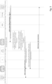
- measures for integrating a wireless communication system based, for example, on 3GPP standard, into a TSN or other Ethernet based system are described, wherein the TSN or other Ethernet based system uses any configuration, in particular a distributed configuration as described above. Principles of such an integration are described in the following on the basis of a configuration as shown in Fig. 1 .
- a TSN End Station "A" 100 and a TSN End Station B 300 represent potential parties of a communication via a TSN system by means of a time sensitive communication link.
- the TSN system comprises one or more bridges ( FIG. 1 shows 2 bridges 50 and 200, wherein TSN bridge 50 includes a wireless communication network part using a wireless communication services based on 3GPP technologies, such as a 5GS based network.
- a TSN Translator (TT) 70 and a TSN Translator Client (TTC) 60 which acts on behalf of the TT are introduced as a functionality to integrate a wireless communication network into the TSN network domain in a transparent manner. That is, to the TSN network, the wireless communication service of a wireless communication network acts like any other TSN bridge (e.g. as bridge 200), while the TSN network acts as e.g. a data network to the wireless communication network.
- a translator element or function in particular a TSN translator element or function
- a translator client element or function in particular a TSN translator client element or function
- functions like a so-called network-side TSN translator (NW-TT) and a so-called device-side TSN translator (DS-TT) are defined, which are responsible for translation between TSN and 3GPP domains, similar to the TSN translation (TT) and TSN translator client (TTC) element, for example.
- NW-TT network-side TSN translator
- DS-TT device-side TSN translator
- the DS-TT maps to a TTC
- the TT has a UP part which is defined as part of UPF and named NW-TT
- the CP part which is called TSN AF (TSN Application function).
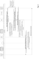
- Fig. 1 the entities of the TSN network are shown by round edged boxes and those of the 3GPP network are shown by sharp edged boxes.
- the wireless network part is simplified by showing a UE 10, a RAN 20 and an CN 30 which constitute the 3GPP network 500 which in turn is enclosed within a dashed line box.
- the solid lines connecting the entities represent the data plane and the dotted lines the control plane.
- the TT 70 and the TTC 60 shown by bold rounded boxes enable the transparent integration of the TSN network and the 3GPP network.
- the round edged box 50 consisting of TT 70, TTC 60, and 3GPP network 500 constitute the logical TSN bridge 50 formed on top of the 3GPP network.
- a network management and orchestration entity (M&O) 400 which is used for managing the network, for example, or represents a network engineering tool.
- the M&O 400 provides data for processing conducted according to some examples of embodiments (later described).
- the M&O 400 includes, for example, management concept and architecture, provisioning, network resource model, fault supervision, assurance and performance management, trace management and virtualization management aspects.
- the TSN End Station A 100 is connected to UE 10 via the TTC 60.
- the UE 10 is responsible to establish and handle the wireless connection service for the TSN End station A 100.
- the wireless connection service contains beside the wireless link between UE 10 and RAN 20 also essential CN services to provide for example authentication, mobility, QoS, etc.
- the TT/TTC functions are used which work as a respective intermediator between both domains, i.e. it understands the TSN protocol and maps the TSN network messages into control and user plane messages of the 3GPP network to trigger corresponding actions in the 3GPP network, e.g. to trigger the establishment of a wireless connection with guaranteed QoS, and vice versa.
- the TT/TTC take care of services like the enforcement of priority classes for the traffic, frame translation, gate schedules etc. which are typically offered by the bridges in the wired network to guarantee deterministic communication.
- the TT 70 and TTC 60 are placed on both sides of the 3GPP network, the network (CN) side and the UE side.
- the TT and the TTC are logically part of the same translation between 3GPP and TSN network and hence, according to examples of embodiments, they do not act independently. Treating them as one entity allows to hide the TSN translator at the UE side to the TSN system and to use the TSN translator at the CN side to represent the complete 3GPP network as a TSN bridge to the TSN system.
- the TT (or NW-TT, for example) performs the major part of the translation of the TSN protocols to 3GPP commands and procedures and vice versa.
- the TTC 60 at the UE side acts on behalf of the TT 70 at the CN side and is therefore called TSN translator client (or DS-TT, for example).
- the integration of the TSN translator with the TSN network is done, for example, by implementing the protocols for an TSN bridge, the TSN Ethernet protocol to exchange messages between a TSN bridge with another TSN Ethernet bridge or TSN End Station (user plane traffic, also called data traffic) and the protocol to exchange information with possible control elements of the TSN (e.g. CNC) (control plane).
- 3GPP network interfaces provide a set of functions which are defined for a specific 3GPP release. Therefore, the TT 70 as well as the TTC 60 are designed to adapt to respective new releases. As long as a 3GPP release is not closed, 3GPP may introduce additional interfaces or adaptations to interfaces or even new functional entities which allows for optimizing or simplifying respective handling of the communication for TSN networks.
- An example for such an adaptation is the introduction of the new PDU session type "Ethernet" to handle Ethernet traffic.
- the TT 70 as well as the TTC 60 hide the release specifications to the TSN network. The same is valid for the 3GPP network when the TSN network introduces new functions and interface modifications.
- the TSN End Stations A and B may be, for example, a sensor, controller, actuator or any other industrial device.
- the UE 10 which is shown in Fig. 1 as a separate entity, may be integrated in the End Station A or may be plugged into the TSN end station A.
- the UE 10 represents either an ingress port (UL communication direction) or an egress port (DL communication direction) for the TSN based communication.
- the TTC 60 may also be an integrated part of TSN end station A 100, the UE 10, or both.
- any network function of the communication network can be implemented as a network element on a dedicated hardware, as a software instance running on a dedicated hardware, or as a virtualized function instantiated on an appropriate platform, e.g., a cloud infrastructure.
- the CN 30 shown in Fig. 1 may comprise various elements or network functions.
- the CN NFs comprises e.g. access and mobility functions (AMF), session management functions (SMF), policy control functions (PCF), network exposure function (NEF), user data management (UDM), user plane functions (UPF), application functions (AF) etc.
- AMF access and mobility functions
- SMF session management functions
- PCF policy control functions
- NEF network exposure function
- UDM user data management
- UPF user plane functions
- AF application functions
- additional or alternative elements or functions can be provided.
- TT 70 and TTC 60 work as a respective intermediator between both domains, i.e., the TSN translator understands the TSN protocol and the 3GPP protocols and maps the TSN commands and messages into corresponding actions and messages in a 3GPP network providing 5G and vice versa.
- TSN Translator Two key types of information messages are differentiated by the TSN Translator:
- Similar translation shall be performed when the TSN frames or packets arrive at the TSN translator ingress ports.
- the priority queues shall be implemented at the translator or the translator client or both.
- the UP part of the TSN Translator is realized either as:
- TSN Translator Client Similar to the TSN Translator, CP and UP translation is performed by the TSN Translator Client.
- the TSN Translator Client works on behalf of the TSN Translator so that the TSN Translator Client, 3GPP network and TSN Translator together appear to be a TSN bridge for the TSN network and the TSN end station A.
- the TSN translator client offers a blocked security port to the TSN end station A, so that the TSN end station A can send authentication related messages to the TSN system.
- TSN translator TT 70 and its TTC 60
- 3GPP 3GPP network
- a TSN (or Ethernet based) system including a distributed configuration as described above, it is necessary to support SRP in the 5GS bridge shown e.g. in Fig. 1 , in order to enable the propagation of Talker/Listener declarations within the 5G network as well as the adequate resource management within 5GS.
- measures are provided which allow to control the propagation of messages, such as Talker and Listener declarations as well as actual stream data transmission through the 5GS Bridge so as to enable the establishment of required TSN streams between Talker(s) and Listener(s) while minimizing the amount of resources used within 5GS.
- messages such as Talker and Listener declarations
- PDU sessions and QoS flows suitable for the propagation of Talker and Listener declarations are established, wherein corresponding ports within the 5GS bridge are (pre-)configured in a way to allow forwarding of declarations with selected destination addresses, and to enable back-propagation of declarations from Listener(s).
- failure indications such as "Talker Failed” or "Listener Failed” messages, e.g., in case an accumulated latency exceeds defined thresholds, are processed.
- corresponding measures allowing to conduct a control enabling the transmission of a data stream between the Talker(s) and the Listener(s) are provided by means of a so-called 3GPP-SRP function.
- the 3GPP-SRP function according to examples of embodiments enables the self-management of a 5GS Bridge according to the TSN distributed configuration model.
- the 3GPP-SRP function complements the TSN Translator functions (network and UE side).
- the 3GPP-SRP functions 65 and 75 enable the support of SRP and the distributed TSN configuration model by a 5GS acting as a TSN Bridge ("5GS Bridge").
- 5GS Bridge TSN Bridge
- other parts of the communication network can be used for accommodating the 3GPP-SRP function, such as a core network element or function, the UE or the like.
- the following functionalities 1 to 4 are comprised within the 3GPP-SRP function 65 or 75:
- a function referred to as 3GPP-SRP function is introduced which enables, for example, the 5GS to handle SRP protocol used in distributed TSN configuration model in a way which optimizes the resource usage of 3GPP network while providing the performance required to support the TSN streams within 3GPP network.
- the 3GPP-SRP function according to examples of embodiments enables the self-management of 5GS Bridge according to the TSN distributed configuration model, considering TSN stream requirements as well as supporting procedures defined by the SRP, comprising handling of SRP procedures during the Talker declaration propagation, Listener declaration propagation as well as supporting the TSN stream transmission.
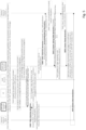
- Fig. 2 shows a signaling diagram illustrating a procedure related to propagation of a declaration message according to some examples of embodiments. Specifically, Fig. 2 is related to above indicated points 1 and 2, i.e. the 5GS Bridge resource management and ports configurations and a calculation/estimation of suitable capabilities of the 5GS Bridge.
- the 3GPP Network is configured. For example, IMSI, 5QI for default PDU session in UDM are configured. Furthermore, TSN End Station IDs (i.e. end stations 100 and 300) along with their capabilities and requirements are indicated to the M&O 400 and stored therein.
- the TSN End Station A 100 is connected via 3GPP-SRP Translator Client 60, 65 to UE 10, and the 3GPP Network is connected via 3GPP-SRP Translator 70, 75 to the TSN Network (here, to TSN Bridge 200).
- a default PDU session is established in the 3GPP network.
- This procedure includes, for example, UE authentication in the 3GPP network with the CN 30.
- S230 a control session between the 3GPP-SRP Translator Client 60 and 3GPP-SRP Translator 70 is established.
- SRP relevant information such as port configuration information, can be exchanged between the TT and the TTC.
- the 3GPP-SRP Translatorfunction 75 derives suitable port configuration (e.g. rules on forwarding or filtering Talker declarations and corresponding Listener declarations with certain destination address and VLAN ID).
- suitable port configuration e.g. rules on forwarding or filtering Talker declarations and corresponding Listener declarations with certain destination address and VLAN ID.
- filtering and forwarding rules can be defined in databases, such as filtering database (FDB), which contains filtering which is either a) static, and explicitly configured by management entities; or b) dynamic and is updated by the bridge operation and the protocols it supports.
- FDB filtering database
- the 5GS Bridge i.e. 3GPP-SRP Translator function 75
- 3GPP-SRP Translator function 75 is able to make such pre-configuration on the basis of information derived in S240, in which information about available devices (specifically, end stations of the TSN network) and their capabilities/requirements are obtained.
- stream history information which are stored e.g. during a setup phase and an operational phase is provided.
- the corresponding information is available at the M&O functions 400, as indicated in S210.
- the following example is useful.
- a newly added end-device is a temperature sensor which is deployed on top of existing temperature sensors in order to support the remote process automation in a factory
- the advertisement from such a sensor should be forwarded in a way to reach the same actuator (i.e. listener end station) collecting other temperature measurements from other sensors which were deployed beforehand.
- the 3GPP-SRP Translator 75 is able to act accordingly.
- the 3GPP-SRP Translator function 75 When having obtained the information in S240, the 3GPP-SRP Translator function 75 conducts the 5GS Bridge port configuration and PDU session/QoS flow setup/modification for Talker declaration propagation in S250. That is, the 3GPP-SRP Translator 75 triggers the setup or modification of a PDU session/QoS flows to be used for Talker/Listener declarations ("declaration propagation PDU session/QoS flow") and derives the corresponding port configurations.
- an existing PDU session can be used for forwarding information between a pair TSN Translator-TSN Translator Client.
- PDU sessions used for transmission of SRP messages i.e. the declaration messages
- other type of information such as LLDP messages, etc.
- the TSN end station A 100 transmits, as a Talker, a Talker Advertise declaration which includes, for example, a streamlD, a rank, a traffic specification, an information field indicating an accumulated latency, a UserToNetworkRequirements.maximum latency indication, status information, information about failed interfaces etc.
- a Talker Advertise declaration which includes, for example, a streamlD, a rank, a traffic specification, an information field indicating an accumulated latency, a UserToNetworkRequirements.maximum latency indication, status information, information about failed interfaces etc.
- the 3GPP-SRP Translator client function 65 of the TTC 60 starts propagation of the Talker declaration towards the 3GPP-SRP Translator function 75 by using the established PDU sessions/QoS flows, i.e. the declaration propagation PDU session/QoS flow.
- resources required for the declaration propagation such as the QoS characteristics/capabilities of "declaration propagation PDU session/QoS flow” may be lower compared to the characteristics/capabilities of the PDU sessions/QoS flows that are finally set up and used for actual stream data transmission. Due to this, it is possible to save resources at the 5GS by avoiding the setup of QoS flows with high QoS characteristics/capabilities for a sole declaration propagation (e.g. Talker Advertise, Listener Ready declarations), which, depending on the Listeners' demand as well as the capability of the rest of the bridges on the path, may not even result in actual stream transmission.
- a sole declaration propagation e.g. Talker Advertise, Listener Ready declarations
- FailedInterface parameter provides a list of one or more physical interfaces (ports) in the failed bridge or end station). Based on such information, the 3GPP-SRP function 75 can derive a comprehensive overview on the situation in the network and the network capabilities, e.g. which particular bridge on which port(s) failed to provide which latency requirements.
- the 3GPP-SRP Translator function 75 conducts in S295 an estimation on a suitable latency to be added in the AccumulatedLatency field. That is, a latency value caused by the 3GPP network is determined (worst case scenario is considered), wherein this value is then added to the accumulated latency indication being part of the Talker advertise declaration received in S270.
- the estimation on the suitable latency to be added in the AccumulatedLatency field of declaration is based on
- the 3GPP-SRP function (e.g. one or both of 3GPP-SRP functions 65 and 75) is configured to store information about latency values for later usage.
- the latency value derived for the 3GPP network and to be added to the previously received accumulated latency indication is stored.
- the Talker Advertise declaration received in S270 is propagated further via the previously determined ports of the 5GS bridge.
- the Talker Advertise declaration in S298 is updated with regard to the AccumulatedLatency field by including the latency value determined in S295.
- the 5GS bridge has propagated the Talker advertise declaration in the TSN network towards the listener side.
- Fig. 3 a signaling diagram illustrating a further procedure related to propagation of a declaration message according to some examples of embodiments is shown. Specifically, Fig. 3 is related to above indicated point 3, i.e. the setup or modification of PDU sessons/QoS flows.
- the Listener e.g. TSN end station B 300 of Fig. 1
- the Listener sends in S320 a Listener Ready declaration back to the Talker.
- the Listener Ready declaration indicates, for example, the stream ID, UserToNetworkRequirements. MaxLatency, Status information, failed interfaces, etc.
- the Bridges on the selected path between Talker and Listener propagate the Listener Ready declaration back through the ports where the corresponding Talker Advertise (with the same stream ID) had been propagated before. During such back-propagation the bridges reserve the required resources for transmission of the stream. Consequently, at this point in time, also the 5GS Bridge reserves the required resources for transmission of the advertised stream.
- the 3GPP-SRP Translator function 75 uses the existing declaration propagation PDU sessions/QoS flows to back-propagate the Listener Ready declaration. Furthermore, 3GPP-SRP Translatorfunction 75 triggers the setup or modification of PDU session/QoS flow based on the estimated latency included in the AccumulatedLatency field during Talker advertisement propagation (which is stored, as described above).
- Listener declaration of type Ready i.e. Listener Ready
- Listener requirements match the advertised stream characteristics, e.g. final AccumulatedLatency in Talker declaration does not exceed MaxLatency in corresponding Listener declaration.
- the 3GPP-SRP Translator function 70, 75 propagates back the Listener Ready declaration via the already established PDU session/QoS flow ("declaration propagation PDU session/QoS flow" already used for Talker declaration propagation) in S340 and triggers in S350, by providing, to the 3GPP-SRP Translator Client, information on PDU session/QoS flow for use for the actual stream data transmission, the modification of already existing PDU session or alternatively a setup of new PDU session/QoS flow with the promised QoS characteristics that will be used for actual stream data transmission in S360.
- the 5GS Bridge groups such requests and back-propagates such information in a common message. That is, the 3GPP-SRP function merges several Listener declarations from different ports into a single Listener declaration. The common message is then sent on the egress port which was used for the associated Talker registration (providing the path to the corresponding Talker).
- Fig. 4 is related to above indicated point 4, i.e. the modification of existing (or alternatively offering/setting up of different) PDU sessions/QoS flows within the 5GS Bridge on demand.
- the Talker Advertise declaration has propagated to the Listener (similar to S310). However, in the case according to Fig. 4 , the latency requirements cannot be fulfilled. For example, the Listener's MaxLatency requirement is lower than AccumulatedLatency of corresponding Talker Advertise declaration.
- a failure message is propagated through the network.
- the message in S420 is sent when AccumulatedLatency in a bridge is exceeding the MaxLatency of Talker.
- the further propagation is suspended or postponed for a further processing.
- the 5GS bridge can provide a QoS flow with better QoS characteristics (i.e. lower latency) than initially reported in the AccumulatedLatency included in the Talker advertise declaration, for example, sent in S298 of Fig. 2 .
- QoS characteristics i.e. lower latency
- the 3GPP-SRP Translator 70, 75 updates, in S440, the Talker Advertise message corresponding to the received failure message (Talker Failed message or Listener Ready Failed message) by indicating a new (updated) accumulated latency based on the re-calculated latency which can be offered in the 5GS part. That is, the latency added to the AccumulatedLatency field is decreased, and a (new) Talker advertise declaration message including the thus updated AccumulatedLatency field is sent in S440 along the path towards the Listener (i.e. from where the failure message in S420 is received).
- the 5GS bridge knows the accumulated value to determine a reduced latency for updating the indication for the accumulated latency value for the updated declaration message sent to the source of the failure message.
- This procedure can be repeated, for example until the decrease of latency does not result in reception of Listener Ready declaration as shown in S420, i.e. in the case that decreased latency satisfies end to end latency requirements of the Talker and Listener.
- the 5GS Bridge will further handle the Listener Ready declaration as described in connection with Fig. 3 , which means that S460 (corresponding to S330), S470 (corresponding to S340) and S480 (corresponding to S350) follow to a reception of a Listener Ready declaration in S450, resulting in a stream data transmission in S490.
- the 3GPP-SRP Translator function stops postponement of the propagation of this message, i.e. the Talker Failed or Listener Asking Failed declaration message is propagated further towards the Talker, resulting in that the corresponding stream and QoS flows will not be setup (i.e. S490 does not happen).
- Fig. 5 showing a further signaling diagram illustrating a procedure related to propagation of a declaration message according to some examples of embodiments.
- Fig. 5 is related to a situation where the 5GS bridge is directly connected to a TSN end station (i.e. TSN end station B) representing the Listener party. It is to be noted that similar processing is also applicable for the case where the Talker is connected directly to 5GS Bridge.
- the Talker/Listener declarations such as Talker Advertise and Listener Ready are propagated by using the declaration propagation PDU session/QoS flow as described above. That is, the processing according to S510 corresponds to S210 of Fig. 2 , the processing according to S520 corresponds to S220 of Fig. 2 ,. the processing according to S530 corresponds to S230 of Fig. 2 , the processing according to S540 corresponds to S250 of Fig. 2 (based on information as derived in S240 of Fig. 2 , for example), the processing according to S550 corresponds to S260 of Fig. 2 , the processing according to S560 corresponds to S270 of Fig. 2 , and the processing according to S570 corresponds to S280 of Fig. 2 , so that a repetition of the respective explanations thereof is omitted here.
- the 5GS Bridge is the only bridge on the path from Talker to Listener(s). Consequently, the AccumulatedLatency added to the Talker declarations in the 5GS bridge can be equal to the Talker's maximum latency ( MaxLatency) requirements.
- MaxLatency the Talker's maximum latency
- the 3GPP-SRP Translator function 70, 75 knows that there is no further TSN bridge, i.e. the end station is directly connected to the 5GS bridge, it uses the MaxLatency value as Accumulated Latency indication, i.e. the update of the Talker advertise declaration considers the MaxLatency value.
- the 5GS Bridge guarantees the upper bound of latency requirement.
- the thus updated Talker advertise declaration is propagated in S590 to the TSN end station B 300 (the Listener), similar to S298 of Fig. 2 .
- Listener Ready declaration message is received (this corresponds to S650) and corresponding procedure for modification (alternatively a setup) of PDU session/QoS flow with guaranteed characteristics can be triggered by 3GPP-SRP Translator (S660). This will be also communicated to 3GPP-SRP Translator Client. Finally, the Talker starts sending the stream data using the established PDU session/QoS stream (S670).
- Fig. 6 shows a flow chart of a processing executed by a network element or function acting as a 3GPP-SRP Translator or 3GPP-SRP Translator Client according to some examples of embodiments, which conducts a control processing for enabling transmission of a data stream between a talker and a listener party according to examples of embodiments of the disclosure.
- the following procedure is conducted in connection with a wireless communication network, such as a wireless communication network is based on a 3GPP standard.
- a control of transmission of a declaration message related to a stream reservation procedure between the at least one talker party and at least one listener party via a wireless communication network forming a bridge element of a communication system is conducted.
- the control comprises to select at least one specific set of ingress and egress port pairs in the wireless communication network for declaration message propagation.
- the declaration message comprises an indication for a maximum latency acceptable for the source of the declaration message (e.g. Talker or Listener), and an indication for an accumulated latency indicating a latency provided by a signaling path the declaration message had used so far.
- control of transmission of the declaration message is conducted by establishing at least one PDU session or QoS flow between end points (i.e. entry and exit points of the wireless network, e.g. TT and TTC) for the at least one talker party side and the at least one listener party side.
- end points i.e. entry and exit points of the wireless network, e.g. TT and TTC
- at least one PDU session or QoS flow between end points in the wireless communication network for the at least one talker party side and the at least one listener party side is modified.
- an already established PDU session or QoS flow between end points in the wireless communication network for the at least one talker party side and the at least one listener party side is re-used.
- information about capabilities of terminal devices e.g. end stations
- the terminal devices providing data to be transmitted between the at least one talker party and the at least one listener party
- stream history data regarding setup or operational phase of previous streams to and from terminal devices providing data to be transmitted between the at least one talker party and the at least one listener party is received and processed.
- end stations representing the at least one talker party and the at least one listener party form a subset of the terminal devices.
- the processed information is then used for establishing or modifying the at least one PDU session or QoS flow between the end points in the wireless communication network for the at least one talker party side and the at least one listener party side.
- the at least one PDU session or QoS flow between the end points in the wireless communication network for the at least one talker party side and the at least one listener party side is specified for propagation of the declaration message (i.e. the resources/setting can be specified for declaration message propagation and be different to e.g. stream transmission settings).
- a latency value representing a worst-case latency for a data transmission via the wireless communication network is determined. On this basis, the indication for the accumulated latency in the declaration message is updated.
- the accumulated latency indicating a latency provided by a signaling path the declaration message had used so far is stored, e.g. for later usage.
- the wireless communication network has to know the accumulated value to determine a reduced latency for updating the indication for the accumulated latency value and to send an updated declaration message to the source of the failure message.
- the declaration message including the updated indication for the accumulated latency is forwarded to the destination (e.g. the Listener).
- monitoring is conducted as to whether a failure indication message is provided from the side of the at least one talker party and the side of the at least one listener party.
- the failure indication message indicates that a latency requirement indicated by the declaration message cannot be fulfilled.
- a value for updating the indication for the accumulated latency in the declaration message is determined by using at least one of capabilities of terminal devices (end stations representing the at least one talker party and the at least one listener party form a subset of the terminal devices) providing data to be transmitted between the at least one talker party and the at least one listener party, requirements of terminal devices providing data to be transmitted between the at least one talker party and the at least one listener party, and stream history data regarding setup or operational phase of previous streams to and from devices providing services for data transmission. Furthermore, a comparison between the maximum latency indicated in the declaration message and an accumulated latency value accumulated on the signaling path the declaration message had used so far is conducted. In addition, information based on failure indication messages indicating that a latency requirement indicated by the declaration message cannot be fulfilled is used.
- the indication for the accumulated latency in the declaration message is updated by using the maximum latency indicated in the declaration message.
- the correspondingly updated declaration message is then forwarded.
- a declaration message from the at least one listener party is provided indicating that the listener intends to receive data offered by the at least one talker party. Then, resources of the wireless communication network, for a PDU session or a QoS flow, required for transmission of the data between the at least one talker party and the at least one listener party are set up or modified.
- the declaration message from the at least one listener party is forwarded to the at least one talker party by using ports in the wireless communication network which are used for a previous transmission of the declaration message from the at least one talker party to the at least one listener party.
- setup or modification of the resources is triggered on the basis of a latency value used for updating an indication of the accumulated latency.
- this latency value is added to the accumulated value in the talker declaration for which the 5GS bridge received listener ready declaration. That is, setup or modification of the resources is triggered in case a positive feedback from listener side is received, i.e. the Listener ready declaration, for example.
- a latency requirement of the at least one talker party or the at least one listener party is not fulfilled, e.g. due to a failure message. Then, forwarding of a corresponding declaration message including an indication that the latency requirement is not fulfilled to the at least one talker party is postponed/suspended. It is checked whether a modification of resources of the wireless communication network is possible for reducing a latency caused by the wireless communication network in a data transmission between the at least one talker party and the at least one listener party.
- a reduced latency value available in the wireless communication network is determined, and the indication for the accumulated latency in the declaration message is correspondingly updated on the basis of the determined reduced latency value.
- An updated declaration message including the updated indication for the accumulated latency is sent back to the at least one listener party by which it was indicated that the latency requirement of the at least one talker party or the at least one listener party is not fulfilled.
- the declaration message including the indication that the latency requirement is not fulfilled is (finally) forwarded to the at least one talker party.
- the wireless communication network forms a bridge element for a TSN system or Ethernet based networking system, wherein a device forming a mobile terminal element or function or a UE element or function of the wireless communication network represents one end point of the bridge element being connectable with at least one end station or another bridge element of the TSN system or Ethernet based networking system, and a core network element or function of the wireless communication network represents another end point of the bridge element towards another end station or another bridge element of the TSN system or Ethernet based networking system.
- a network-side translator element or function (e.g. the TT) is connected to or part of a core network element or function of the wireless communication network and a device-side translator element or function (e.g.
- the TTC is connected to or part of the device forming a mobile terminal element or function or a UE element or function.
- the element or function providing the above processing is part of at least one of the network-side translator element or function, the device-side translator element or function, and a core network element or function of the wireless communication network.
- Fig. 7 shows a diagram of a network element or function acting as a 3GPP-SRP Translator or 3GPP-SRP Translator Client according to some examples of embodiments, as described in connection with Figs. 1 to 5 , which is configured to conduct a control processing for enabling transmission of a data stream between a talker and a listener party according to examples of embodiments of the disclosure.
- the network element or function like the 3GPP-SRP Translator or 3GPP-SRP Translator Client, may include further elements or functions besides those described herein below.
- the element or function may be also another device or function having a similar task, such as a chipset, a chip, a module, an application etc., which can also be part of a network element or attached as a separate element to a network element, or the like. It should be understood that each block and any combination thereof may be implemented by various means or their combinations, such as hardware, software, firmware, one or more processors and/or circuitry.
- the network element or function 70 shown in Fig. 6 may include a processing circuitry, a processing function, a control unit or a processor 701, such as a CPU or the like, which is suitable for executing instructions given by programs or the like related to the control procedure.
- the processor 701 may include one or more processing portions orfunctions dedicated to specific processing as described below, or the processing may be run in a single processor or processing function. Portions for executing such specific processing may be also provided as discrete elements or within one or more further processors, processing functions or processing portions, such as in one physical processor like a CPU or in one or more physical or virtual entities, for example.
- Reference sign 702 and 703 denote input/output (I/O) units or functions (interfaces) connected to the processor or processing function 701.
- the I/O units 702 may be used for communicating with a TSN network elements, such as end stations or bridges, as described in connection with Figs. 1 to 5 , for example.
- the I/O units 703 may be used for communicating with network elements or functions of the wireless communication network e.g. the 3GPP network, as described in connection with Figs. 1 to 5 .
- the I/O units 702 and 703 may be combined units including communication equipment towards several entities, or may include a distributed structure with a plurality of different interfaces for different entities.
- Reference sign 704 denotes a memory usable, for example, for storing data and programs to be executed by the processor or processing function 701 and/or as a working storage of the processor or processing function 701. It is to be noted that the memory 704 may be implemented by using one or more memory portions of the same or different type of memory.
- the processor or processing function 701 is configured to execute processing related to the above described control processing.
- the processor or processing circuitry or function 701 includes one or more of the following sub-portions.
- Sub-portion 7011 is a processing portion which is usable as a portion for controlling declaration transmission.
- the portion 7011 may be configured to perform processing according to S700 of Fig. 6 .
- the processor or processing circuitry or function 701 may include a sub-portion 7012 usable as a portion for updating a latency indication.
- the portion 7012 may be configured to perform a processing according to S710 of Fig. 6 .
- the processor or processing circuitry or function 701 may include a sub-portion 7013 usable as a portion for forwarding declaration messages.
- the portion 7013 may be configured to perform a processing according to S720 of Fig. 6 .
- an apparatus for use by a network element or function configured to conduct a control processing for enabling transmission of a data stream between at least one talker party and at least one listener party
- the apparatus comprising means configured to conduct control of transmission of a declaration message related to a stream reservation procedure between the at least one talker party and at least one listener party via a wireless communication network forming a bridge element of a communication system, the control comprising selecting at least one specific set of ingress and egress port pairs in the wireless communication network for declaration message propagation, wherein the at least one declaration message comprises an indication for a maximum latency acceptable for the source of the declaration message, and an indication for an accumulated latency indicating a latency provided by a signaling path the declaration message had used so far.
- the above defined apparatus may further comprise means for conducting at least one of the processing defined in the above described methods, for example a method according to that described in connection with Fig 6 .
- a non-transitory computer readable medium comprising program instructions for causing an apparatus to perform, when conducting a control processing for enabling transmission of a data stream between at least one talker party and at least one listener party, at least the following: conducting control of transmission of a declaration message related to a stream reservation procedure between the at least one talker party and at least one listener party via a wireless communication network forming a bridge element of a communication system, the control comprising selecting at least one specific set of ingress and egress port pairs in the wireless communication network for declaration message propagation, wherein the at least one declaration message comprises an indication for a maximum latency acceptable for the source of the declaration message, and an indication for an accumulated latency indicating a latency provided by a signaling path the declaration message had used so far.
Claims (15)
- Appareil destiné à être utilisé par un élément de réseau ou une fonction (70), configuré pour mener un traitement de commande afin de permettre la transmission d'un flux de données entre au moins une partie émettrice et au moins une partie réceptrice, l'appareil comprenantau moins une circuiterie de traitement (701), etau moins une mémoire (704) pour stocker des instructions à exécuter par la circuiterie de traitement,dans lequel la au moins une mémoire et les instructions sont configurées pour, avec la au moins une circuiterie de traitement, amener l'appareil au moins :à mener une commande de transmission d'un message de déclaration relatif à une procédure de réservation de flux entre la au moins une partie émettrice et la au moins une partie réceptrice via un réseau de communication sans fil formant un élément de pont d'un système de communication (S700), la commande comprenant la sélection d'au moins un jeu spécifique de paires de ports d'entrée et de sortie dans le réseau de communication sans fil pour la propagation de message de déclaration, caractérisé en ce quele au moins un message de déclaration comprend une indication d'un temps de latence maximal acceptable pour la source du message de déclaration, et une indication d'un temps de latence cumulé indiquant un temps de latence prévu par un chemin de signalisation que le message de déclaration a utilisé jusqu'à présent (S710).
- Appareil selon la revendication 1, dans lequel la au moins une mémoire et les instructions sont en outre configurées pour, avec la au moins une circuiterie de traitement, amener l'appareil au moins :
à mener une commande de transmission du message de déclaration en effectuant l'une des étapes suivantes :établir au moins une session d'unité de données par paquets ou un flux de qualité de service entre des points d'extrémité dans le réseau de communication sans fil pour le côté au moins une partie émettrice et le côté au moins une partie réceptrice,modifier au moins une session d'unité de données par paquets ou un flux de qualité de service entre des points d'extrémité dans le réseau de communication sans fil pour le côté au moins une partie émettrice et le côté au moins une partie réceptrice, etréutiliser une session d'unité de données par paquets ou un flux de qualité de service déjà établis entre des points d'extrémité dans le réseau de communication sans fil pour le côté au moins une partie émettrice et le côté au moins une partie réceptrice. - Appareil selon la revendication 1 ou 2, dans lequel la au moins une mémoire et les instructions sont en outre configurées pour, avec la au moins une circuiterie de traitement, amener l'appareil au moins :à recevoir et à traiter au moins l'une des informations concernantdes capacités de dispositifs terminaux fournissant des données à transmettre entre la au moins une partie émettrice et la au moins une partie réceptrice,des exigences de dispositifs terminaux fournissant des données à transmettre entre la au moins une partie émettrice et la au moins une partie réceptrice, etdes données d'historique de flux concernant la configuration ou la phase opérationnelle de flux précédents vers et depuis des dispositifs terminaux fournissant des données à transmettre entre la au moins une partie émettrice et la au moins une partie réceptrice,
età utiliser les informations traitées pour établir ou modifier la au moins une session d'unité de données par paquets ou un flux de qualité de service entre le points d'extrémité dans le réseau de communication sans fil pour le côté au moins une partie émettrice et le côté au moins une partie réceptrice. - Appareil selon l'une des revendications 1 à 3, dans lequel la au moins une mémoire et les instructions sont en outre configurées pour, avec la au moins une circuiterie de traitement, amener l'appareil au moins :à stocker le temps de latence cumulé indiquant un temps de latence prévu par un chemin de signalisation que le message de déclaration a utilisé jusqu'à présent,à déterminer, sur la base de capacités de ressources du réseau de communication sans fil, une valeur de temps de latence représentant un temps de latence le plus défavorable pour une transmission de données via le réseau de communication sans fil,à mettre à jour l'indication du temps de latence cumulé dans le message de déclaration sur la base de la valeur de temps de latence déterminé, età transférer le message de déclaration comportant l'indication mise à jour pour le temps de latence cumulé.
- Appareil selon la revendication 4, dans lequel la au moins une mémoire et les instructions sont en outre configurées pour, avec la au moins une circuiterie de traitement, amener l'appareil au moins :
à surveiller si un message d'indication d'échec est fourni du côté de la au moins une partie émettrice et du côté de la au moins une partie réceptrice, le message d'indication d'échec indiquant qu'une exigence de temps de latence indiquée par le message de déclaration ne peut pas être satisfaite. - Appareil selon l'une des revendications 1 à 3, dans lequel la au moins une mémoire et les instructions sont en outre configurées pour, avec la au moins une circuiterie de traitement, amener l'appareil au moins :à mettre à jour, dans le cas où la au moins une partie émettrice et la au moins une partie réceptrice sont directement connectés à un point d'extrémité du réseau de communication sans fil, l'indication du temps de latence cumulé dans le message de déclaration en utilisant le temps de latence maximal indiqué dans le message de déclaration, età transférer le message de déclaration comportant l'indication mise à jour pour le temps de latence cumulé.
- Appareil selon l'une des revendications 1 à 3, dans lequel la au moins une mémoire et les instructions sont en outre configurées pour, avec la au moins une circuiterie de traitement, amener l'appareil au moins :à déterminer qu'un message de déclaration provenant de la au moins une partie réceptrice est fourni et qu'il indique que la partie réceptrice a l'intention de recevoir des données offertes par la au moins une partie émettrice,à configurer ou à modifier des ressources du réseau de communication sans fil pour une session d'unité de données condensées ou un flux de qualité de service nécessaires à la transmission des données entre la au moins une partie émettrice et la au moins une partie réceptrice.
- Appareil selon la revendication 7, dans lequel la au moins une mémoire et les instructions sont en outre configurées pour, avec la au moins une circuiterie de traitement, amener l'appareil au moins :
à transférer le message de déclaration provenant de la au moins une partie réceptrice à la au moins une partie émettrice en utilisant des ports dans le réseau de communication sans fil qui sont utilisés pour une transmission précédente du message de déclaration de la au moins une partie émettrice à la au moins une partie réceptrice. - Appareil selon l'une des revendications 1 à 8, dans lequel la au moins une mémoire et les instructions sont en outre configurées pour, avec la au moins une circuiterie de traitement, amener l'appareil au moins :à déterminer qu'une exigence de temps de latence de la au moins une partie émettrice ou de la au moins une partie réceptrice n'est pas satisfaite,à reporter le transfert d'un message de déclaration comportant une indication selon laquelle l'exigence de temps de latence n'est pas satisfaite à la au moins une partie émettrice, età vérifier si une modification de ressources du réseau de communication sans fil est possible pour réduire un temps de latence causé par le réseau de communication sans fil dans une transmission de données entre la au moins une partie émettrice et la au moins une partie réceptrice.
- Procédé pour utiliser dans un élément de réseau ou une fonction (70) configuré pour mener un traitement de commande afin de permettre la transmission d'un flux de données entre au moins une partie émettrice et au moins une partie réceptrice, le procédé comprenantla réalisation d'une commande de transmission d'un message de déclaration relatif à une procédure de réservation de flux entre la au moins une partie émettrice et la au moins une partie réceptrice via un réseau de communication sans fil formant un élément de pont d'un système de communication (S700),la commande comprenant la sélection d'au moins un jeu spécifique de paires de ports d'entrée et de sortie dans le réseau de communication sans fil pour la propagation de message de déclaration, caractérisé en ce que le au moins un message de déclaration comprend une indication d'un temps de latence maximal acceptable pour la source du message de déclaration, et une indication d'un temps de latence cumulé indiquant un temps de latence prévu par un chemin de signalisation que le message de déclaration a utilisé jusqu'à présent (S710).
- Procédé selon la revendication 10, comprenant en outre
la réalisation d'une commande de transmission du message de déclaration en effectuant l'une des étapes suivantes :établir au moins une session d'unité de données par paquets ou un flux de qualité de service entre des points d'extrémité dans le réseau de communication sans fil pour le côté au moins une partie émettrice et le côté au moins une partie réceptrice,modifier au moins une session d'unité de données par paquets ou un flux de qualité de service entre des points d'extrémité dans le réseau de communication sans fil pour le côté au moins une partie émettrice et le côté au moins une partie réceptrice, etréutiliser une session d'unité de données par paquets ou un flux de qualité de service déjà établis entre des points d'extrémité dans le réseau de communication sans fil pour le côté au moins une partie émettrice et le côté au moins une partie réceptrice. - Procédé selon l'une des revendications 10 à 11, comprenant en outrele stockage du temps de latence cumulé indiquant un temps de latence prévu par un chemin de signalisation que le message de déclaration a utilisé jusqu'à présent,la détermination, sur la base de capacités de ressources du réseau de communication sans fil, d'une valeur de temps de latence représentant un temps de latence le plus défavorable pour une transmission de données via le réseau de communication sans fil,la mise à jour de l'indication du temps de latence cumulé dans le message de déclaration sur la base de la valeur de temps de latence déterminé, etle transfert du message de déclaration comportant l'indication mise à jour pour le temps de latence cumulé.
- Procédé selon l'une des revendications 10 à 11, comprenant en outrela mise à jour, dans le cas où la au moins une partie émettrice et la au moins une partie réceptrice sont directement connectés à un point d'extrémité du réseau de communication sans fil, de l'indication du temps de latence cumulé dans le message de déclaration en utilisant le temps de latence maximal indiqué dans le message de déclaration, etle transfert du message de déclaration comportant l'indication mise à jour pour le temps de latence cumulé.
- Procédé selon l'une des revendications 10 à 13, comprenant en outrela détermination du fait qu'un message de déclaration provenant de la au moins une partie réceptrice est fourni et qu'il indique que la partie réceptrice a l'intention de recevoir des données offertes par la au moins une partie émettrice,la configuration ou la modification de ressources du réseau de communication sans fil pour une session d'unité de données condensées ou un flux de qualité de service nécessaires à la transmission des données entre la au moins une partie émettrice et la au moins une partie réceptrice.
- Produit de programme informatique pour un ordinateur, comportant des portions de code logiciel pour réaliser les étapes selon l'une des revendications 10 à 14 lorsque ledit produit est exécuté sur l'ordinateur.
Applications Claiming Priority (1)
| Application Number | Priority Date | Filing Date | Title |
|---|---|---|---|
| PCT/EP2019/069769 WO2021013338A1 (fr) | 2019-07-23 | 2019-07-23 | Intégration d'un réseau de communication dans un système de réseautage sensible au temps (tsn) |
Publications (2)
| Publication Number | Publication Date |
|---|---|
| EP4005171A1 EP4005171A1 (fr) | 2022-06-01 |
| EP4005171B1 true EP4005171B1 (fr) | 2023-05-10 |
Family
ID=67441108
Family Applications (1)
| Application Number | Title | Priority Date | Filing Date |
|---|---|---|---|
| EP19745093.5A Active EP4005171B1 (fr) | 2019-07-23 | 2019-07-23 | Intégration d'un réseau de communication dans un système de réseautage sensible au temps (tsn) |
Country Status (2)
| Country | Link |
|---|---|
| EP (1) | EP4005171B1 (fr) |
| WO (1) | WO2021013338A1 (fr) |
Families Citing this family (7)
| Publication number | Priority date | Publication date | Assignee | Title |
|---|---|---|---|---|
| CN113645661A (zh) * | 2019-09-27 | 2021-11-12 | 腾讯科技(深圳)有限公司 | 终端执行的方法以及相应的终端、计算机可读存储介质 |
| EP3879764B1 (fr) * | 2020-03-11 | 2023-08-23 | ABB Schweiz AG | Transport d'un message provenant d'un terminal industriel sur un réseau ethernet |
| CN117597901A (zh) * | 2021-07-13 | 2024-02-23 | 瑞典爱立信有限公司 | 用于时间敏感网络的域间配置的方法和装置 |
| CN113554225B (zh) * | 2021-07-22 | 2023-09-26 | 浙江理工大学 | 一种基于藤壶交配算法的流水车间人力调度优化方法 |
| CN117678284A (zh) * | 2021-07-26 | 2024-03-08 | Oppo广东移动通信有限公司 | 一种时间同步方法及装置、终端设备 |
| WO2023184059A1 (fr) * | 2022-03-28 | 2023-10-05 | Zte Corporation | Communication déterministe avec mise en réseau sensible au temps dans un réseau de transport |
| CN117061432A (zh) * | 2022-05-07 | 2023-11-14 | 华为技术有限公司 | 多种网络传输方法及其相关设备 |
Family Cites Families (2)
| Publication number | Priority date | Publication date | Assignee | Title |
|---|---|---|---|---|
| US8838787B2 (en) * | 2011-11-30 | 2014-09-16 | Harman International Industries, Incorporated | System for optimizing latency in an AVB network |
| US20190058668A1 (en) * | 2016-02-24 | 2019-02-21 | Harman International Industries, Incorporated | Data streaming with layer 2 and layer 3 reservations |
-
2019
- 2019-07-23 EP EP19745093.5A patent/EP4005171B1/fr active Active
- 2019-07-23 WO PCT/EP2019/069769 patent/WO2021013338A1/fr unknown
Also Published As
| Publication number | Publication date |
|---|---|
| EP4005171A1 (fr) | 2022-06-01 |
| WO2021013338A1 (fr) | 2021-01-28 |
Similar Documents
| Publication | Publication Date | Title |
|---|---|---|
| EP4005171B1 (fr) | Intégration d'un réseau de communication dans un système de réseautage sensible au temps (tsn) | |
| US11632810B2 (en) | Transparent integration of 3GPP network into TSN based industrial network | |
| US11950127B2 (en) | 5G system support for virtual TSN bridge management, QoS mapping and TSN Qbv scheduling | |
| US20200351752A1 (en) | Integration of communication network in time sensitive networking system | |
| WO2020030165A1 (fr) | Procédé et appareil de transmission de données, et procédé et appareil de commutation de service | |
| EP3844997B1 (fr) | Technique de mise en réseau sensible au temps dans un réseau d'accès radio | |
| US20210243771A1 (en) | Management & orchestration aided transparent of 3gpp network into tsn bases industrial network | |
| US20210306901A1 (en) | Mutual 3gpp-tsn qos adaption and shaping | |
| CN113950852A (zh) | TSN和5GS QoS映射-基于用户面的方法 | |
| WO2020200432A1 (fr) | Mécanisme de contrôle de communication pour trafic à contraintes de temps | |
| CN114009096A (zh) | 应用工作负载路由和网络定义的边缘路由的互通 | |
| WO2020148616A1 (fr) | Mappage qos de système de communication tsn-cellulaire et optimisation ran sur la base d'informations relatives à un motif de trafic tsn | |
| WO2019157855A1 (fr) | Procédé de traitement de paramètre de qualité de service (qos), élément de réseau, système et support de stockage | |
| US20210274529A1 (en) | Communication system | |
| WO2021148152A1 (fr) | Mécanisme pour commander le transfert de flux de données déterministes | |
| US11564187B2 (en) | Method and device for supporting configuration of time synchronization network in mobile communication network | |
| WO2019122497A1 (fr) | Procédure de commande de connexion de communication utilisant des tranches de connexion de communication sélectionnées | |
| WO2019238101A1 (fr) | Système et procédé de transport géré dynamiquement pour réseaux mobiles | |
| EP4144059A1 (fr) | Mécanisme de commande de réservation de flux dans un réseau de communication pour système de réseautage sensible au temps | |
| WO2022222666A1 (fr) | Procédé et appareil de communication | |
| EP4274298A1 (fr) | Mécanisme pour définir une qualité de service dépendante du temps | |
| WO2023042044A1 (fr) | Signalisation de commande entre des entités de réseau 3gpp et un réseau de transport |
Legal Events
| Date | Code | Title | Description |
|---|---|---|---|
| STAA | Information on the status of an ep patent application or granted ep patent |
Free format text: STATUS: UNKNOWN |
|
| STAA | Information on the status of an ep patent application or granted ep patent |
Free format text: STATUS: THE INTERNATIONAL PUBLICATION HAS BEEN MADE |
|
| PUAI | Public reference made under article 153(3) epc to a published international application that has entered the european phase |
Free format text: ORIGINAL CODE: 0009012 |
|
| STAA | Information on the status of an ep patent application or granted ep patent |
Free format text: STATUS: REQUEST FOR EXAMINATION WAS MADE |
|
| 17P | Request for examination filed |
Effective date: 20220223 |
|
| AK | Designated contracting states |
Kind code of ref document: A1 Designated state(s): AL AT BE BG CH CY CZ DE DK EE ES FI FR GB GR HR HU IE IS IT LI LT LU LV MC MK MT NL NO PL PT RO RS SE SI SK SM TR |
|
| DAV | Request for validation of the european patent (deleted) | ||
| DAX | Request for extension of the european patent (deleted) | ||
| REG | Reference to a national code |
Ref country code: DE Ref legal event code: R079 Ref document number: 602019028768 Country of ref document: DE Free format text: PREVIOUS MAIN CLASS: H04L0029060000 Ipc: H04L0065800000 |
|
| GRAP | Despatch of communication of intention to grant a patent |
Free format text: ORIGINAL CODE: EPIDOSNIGR1 |
|
| STAA | Information on the status of an ep patent application or granted ep patent |
Free format text: STATUS: GRANT OF PATENT IS INTENDED |
|
| RIC1 | Information provided on ipc code assigned before grant |
Ipc: H04L 65/65 20220101ALI20221108BHEP Ipc: H04L 65/1069 20220101ALI20221108BHEP Ipc: H04L 65/80 20220101AFI20221108BHEP |
|
| INTG | Intention to grant announced |
Effective date: 20221208 |
|
| GRAS | Grant fee paid |
Free format text: ORIGINAL CODE: EPIDOSNIGR3 |
|
| GRAA | (expected) grant |
Free format text: ORIGINAL CODE: 0009210 |
|
| STAA | Information on the status of an ep patent application or granted ep patent |
Free format text: STATUS: THE PATENT HAS BEEN GRANTED |
|
| AK | Designated contracting states |
Kind code of ref document: B1 Designated state(s): AL AT BE BG CH CY CZ DE DK EE ES FI FR GB GR HR HU IE IS IT LI LT LU LV MC MK MT NL NO PL PT RO RS SE SI SK SM TR |
|
| REG | Reference to a national code |
Ref country code: GB Ref legal event code: FG4D |
|
| REG | Reference to a national code |
Ref country code: AT Ref legal event code: REF Ref document number: 1567854 Country of ref document: AT Kind code of ref document: T Effective date: 20230515 Ref country code: CH Ref legal event code: EP |
|
| REG | Reference to a national code |
Ref country code: DE Ref legal event code: R096 Ref document number: 602019028768 Country of ref document: DE |
|
| REG | Reference to a national code |
Ref country code: IE Ref legal event code: FG4D |
|
| REG | Reference to a national code |
Ref country code: LT Ref legal event code: MG9D |
|
| REG | Reference to a national code |
Ref country code: NL Ref legal event code: MP Effective date: 20230510 |
|
| REG | Reference to a national code |
Ref country code: AT Ref legal event code: MK05 Ref document number: 1567854 Country of ref document: AT Kind code of ref document: T Effective date: 20230510 |
|
| PG25 | Lapsed in a contracting state [announced via postgrant information from national office to epo] |
Ref country code: SE Free format text: LAPSE BECAUSE OF FAILURE TO SUBMIT A TRANSLATION OF THE DESCRIPTION OR TO PAY THE FEE WITHIN THE PRESCRIBED TIME-LIMIT Effective date: 20230510 Ref country code: PT Free format text: LAPSE BECAUSE OF FAILURE TO SUBMIT A TRANSLATION OF THE DESCRIPTION OR TO PAY THE FEE WITHIN THE PRESCRIBED TIME-LIMIT Effective date: 20230911 Ref country code: NO Free format text: LAPSE BECAUSE OF FAILURE TO SUBMIT A TRANSLATION OF THE DESCRIPTION OR TO PAY THE FEE WITHIN THE PRESCRIBED TIME-LIMIT Effective date: 20230810 Ref country code: NL Free format text: LAPSE BECAUSE OF FAILURE TO SUBMIT A TRANSLATION OF THE DESCRIPTION OR TO PAY THE FEE WITHIN THE PRESCRIBED TIME-LIMIT Effective date: 20230510 Ref country code: ES Free format text: LAPSE BECAUSE OF FAILURE TO SUBMIT A TRANSLATION OF THE DESCRIPTION OR TO PAY THE FEE WITHIN THE PRESCRIBED TIME-LIMIT Effective date: 20230510 Ref country code: AT Free format text: LAPSE BECAUSE OF FAILURE TO SUBMIT A TRANSLATION OF THE DESCRIPTION OR TO PAY THE FEE WITHIN THE PRESCRIBED TIME-LIMIT Effective date: 20230510 |
|
| PG25 | Lapsed in a contracting state [announced via postgrant information from national office to epo] |
Ref country code: RS Free format text: LAPSE BECAUSE OF FAILURE TO SUBMIT A TRANSLATION OF THE DESCRIPTION OR TO PAY THE FEE WITHIN THE PRESCRIBED TIME-LIMIT Effective date: 20230510 Ref country code: PL Free format text: LAPSE BECAUSE OF FAILURE TO SUBMIT A TRANSLATION OF THE DESCRIPTION OR TO PAY THE FEE WITHIN THE PRESCRIBED TIME-LIMIT Effective date: 20230510 Ref country code: LV Free format text: LAPSE BECAUSE OF FAILURE TO SUBMIT A TRANSLATION OF THE DESCRIPTION OR TO PAY THE FEE WITHIN THE PRESCRIBED TIME-LIMIT Effective date: 20230510 Ref country code: LT Free format text: LAPSE BECAUSE OF FAILURE TO SUBMIT A TRANSLATION OF THE DESCRIPTION OR TO PAY THE FEE WITHIN THE PRESCRIBED TIME-LIMIT Effective date: 20230510 Ref country code: IS Free format text: LAPSE BECAUSE OF FAILURE TO SUBMIT A TRANSLATION OF THE DESCRIPTION OR TO PAY THE FEE WITHIN THE PRESCRIBED TIME-LIMIT Effective date: 20230910 Ref country code: HR Free format text: LAPSE BECAUSE OF FAILURE TO SUBMIT A TRANSLATION OF THE DESCRIPTION OR TO PAY THE FEE WITHIN THE PRESCRIBED TIME-LIMIT Effective date: 20230510 Ref country code: GR Free format text: LAPSE BECAUSE OF FAILURE TO SUBMIT A TRANSLATION OF THE DESCRIPTION OR TO PAY THE FEE WITHIN THE PRESCRIBED TIME-LIMIT Effective date: 20230811 |
|
| PGFP | Annual fee paid to national office [announced via postgrant information from national office to epo] |
Ref country code: DE Payment date: 20230531 Year of fee payment: 5 |
|
| PG25 | Lapsed in a contracting state [announced via postgrant information from national office to epo] |
Ref country code: FI Free format text: LAPSE BECAUSE OF FAILURE TO SUBMIT A TRANSLATION OF THE DESCRIPTION OR TO PAY THE FEE WITHIN THE PRESCRIBED TIME-LIMIT Effective date: 20230510 |
|
| PG25 | Lapsed in a contracting state [announced via postgrant information from national office to epo] |
Ref country code: SK Free format text: LAPSE BECAUSE OF FAILURE TO SUBMIT A TRANSLATION OF THE DESCRIPTION OR TO PAY THE FEE WITHIN THE PRESCRIBED TIME-LIMIT Effective date: 20230510 |
|
| PG25 | Lapsed in a contracting state [announced via postgrant information from national office to epo] |
Ref country code: SM Free format text: LAPSE BECAUSE OF FAILURE TO SUBMIT A TRANSLATION OF THE DESCRIPTION OR TO PAY THE FEE WITHIN THE PRESCRIBED TIME-LIMIT Effective date: 20230510 Ref country code: SK Free format text: LAPSE BECAUSE OF FAILURE TO SUBMIT A TRANSLATION OF THE DESCRIPTION OR TO PAY THE FEE WITHIN THE PRESCRIBED TIME-LIMIT Effective date: 20230510 Ref country code: RO Free format text: LAPSE BECAUSE OF FAILURE TO SUBMIT A TRANSLATION OF THE DESCRIPTION OR TO PAY THE FEE WITHIN THE PRESCRIBED TIME-LIMIT Effective date: 20230510 Ref country code: EE Free format text: LAPSE BECAUSE OF FAILURE TO SUBMIT A TRANSLATION OF THE DESCRIPTION OR TO PAY THE FEE WITHIN THE PRESCRIBED TIME-LIMIT Effective date: 20230510 Ref country code: DK Free format text: LAPSE BECAUSE OF FAILURE TO SUBMIT A TRANSLATION OF THE DESCRIPTION OR TO PAY THE FEE WITHIN THE PRESCRIBED TIME-LIMIT Effective date: 20230510 Ref country code: CZ Free format text: LAPSE BECAUSE OF FAILURE TO SUBMIT A TRANSLATION OF THE DESCRIPTION OR TO PAY THE FEE WITHIN THE PRESCRIBED TIME-LIMIT Effective date: 20230510 |
|
| REG | Reference to a national code |
Ref country code: DE Ref legal event code: R097 Ref document number: 602019028768 Country of ref document: DE |
|
| PG25 | Lapsed in a contracting state [announced via postgrant information from national office to epo] |
Ref country code: MC Free format text: LAPSE BECAUSE OF FAILURE TO SUBMIT A TRANSLATION OF THE DESCRIPTION OR TO PAY THE FEE WITHIN THE PRESCRIBED TIME-LIMIT Effective date: 20230510 |
|
| PG25 | Lapsed in a contracting state [announced via postgrant information from national office to epo] |
Ref country code: MC Free format text: LAPSE BECAUSE OF FAILURE TO SUBMIT A TRANSLATION OF THE DESCRIPTION OR TO PAY THE FEE WITHIN THE PRESCRIBED TIME-LIMIT Effective date: 20230510 |
|
| REG | Reference to a national code |
Ref country code: CH Ref legal event code: PL |
|
| PLBE | No opposition filed within time limit |
Free format text: ORIGINAL CODE: 0009261 |
|
| STAA | Information on the status of an ep patent application or granted ep patent |
Free format text: STATUS: NO OPPOSITION FILED WITHIN TIME LIMIT |
|
| REG | Reference to a national code |
Ref country code: BE Ref legal event code: MM Effective date: 20230731 |
|
| PG25 | Lapsed in a contracting state [announced via postgrant information from national office to epo] |
Ref country code: LU Free format text: LAPSE BECAUSE OF NON-PAYMENT OF DUE FEES Effective date: 20230723 |
|
| PG25 | Lapsed in a contracting state [announced via postgrant information from national office to epo] |
Ref country code: LU Free format text: LAPSE BECAUSE OF NON-PAYMENT OF DUE FEES Effective date: 20230723 |
|
| 26N | No opposition filed |
Effective date: 20240213 |
|
| GBPC | Gb: european patent ceased through non-payment of renewal fee |
Effective date: 20230810 |