EP4005145B1 - Verfahren zur bereitstellung eines gemeinsamen referenzrahmens zwischen zwei empfängern - Google Patents
Verfahren zur bereitstellung eines gemeinsamen referenzrahmens zwischen zwei empfängern Download PDFInfo
- Publication number
- EP4005145B1 EP4005145B1 EP20742765.9A EP20742765A EP4005145B1 EP 4005145 B1 EP4005145 B1 EP 4005145B1 EP 20742765 A EP20742765 A EP 20742765A EP 4005145 B1 EP4005145 B1 EP 4005145B1
- Authority
- EP
- European Patent Office
- Prior art keywords
- measurement means
- measurement
- transmission channel
- photon
- receiver
- Prior art date
- Legal status (The legal status is an assumption and is not a legal conclusion. Google has not performed a legal analysis and makes no representation as to the accuracy of the status listed.)
- Active
Links
Images

Classifications
-
- H—ELECTRICITY
- H04—ELECTRIC COMMUNICATION TECHNIQUE
- H04L—TRANSMISSION OF DIGITAL INFORMATION, e.g. TELEGRAPHIC COMMUNICATION
- H04L9/00—Cryptographic mechanisms or cryptographic arrangements for secret or secure communications; Network security protocols
- H04L9/08—Key distribution or management, e.g. generation, sharing or updating, of cryptographic keys or passwords
- H04L9/0816—Key establishment, i.e. cryptographic processes or cryptographic protocols whereby a shared secret becomes available to two or more parties, for subsequent use
- H04L9/0852—Quantum cryptography
- H04L9/0858—Details about key distillation or coding, e.g. reconciliation, error correction, privacy amplification, polarisation coding or phase coding
-
- H—ELECTRICITY
- H04—ELECTRIC COMMUNICATION TECHNIQUE
- H04B—TRANSMISSION
- H04B10/00—Transmission systems employing electromagnetic waves other than radio-waves, e.g. infrared, visible or ultraviolet light, or employing corpuscular radiation, e.g. quantum communication
- H04B10/70—Photonic quantum communication
Definitions
- the invention concerns a method to align an entangled photon source and an entangled photon source comprising two receivers, useful for Quantum Key Distribution.
- the first receiver is connected via a first transmission channel to an entangled photon source
- the second receiver is connected via a second transmission channel to the entangled photon source.
- the entangled photon source produces entangled photon pairs, preferably entangled in polarization or time-bin or orbital angular momentum or path, wherein the first photon of each entangled photon pair is sent via the first transmission channel to the first receiver and the second photon of each entangled photon pair is sent via the second transmission channel to the second receiver.
- Quantum Key Distribution is a secure communication method.
- QKD Quantum Key Distribution
- a key for cryptography can be generated between two parties, in the following called two receivers (Alice and Bob). This key can be used to encrypt and decrypt a message.
- QKD methods like those proposed by Bennett and Brassard in “Quantum cryptography: Public Key Distribution and coin-tossing.”, in “Proceedings of IEEE International Conference a Computers, Systems and Signal Processing", Bangalore India, 175-179 (1984 ), or by Bennet, Brassard and Mermin in "Quantum Cryptography without Bell's Theorem” in Phys. Rev. Lett. 68, 557,1992 , an entangled photon source is needed.
- Entangled photon sources are well known, for example as a BBO source from US 6 424 665 B1 or as fiber Sagnac configuration from US 6 897 434 B1 .
- both receivers have to ensure that they agree on the same measurement bases, i.e. the two receivers have to set a common polarization reference frame with the entangled photon source. This was before realized by an iterative alignment of two mutually unbiased measurement bases between the source and the first receiver, and then by an iterative alignment of two mutually unbiased measurement bases between the source and the second receiver.
- this iterative alignment procedure is time-consuming, but the alignment is of crucial importance for the generation of the key.
- a time-bin entangled photon source is known from GB 2 405 294 A with a photon source and two detection modules.
- Each detection module comprises one unbalanced interferometer and two detectors.
- polarization filters are provided before each detector to remove any erroneous orthogonal components of the polarization.
- An objective of the present invention is to provide an apparatus and an improved method to set a common reference frame between two receivers.
- the method to provide a common reference frame between two receivers, preferably for quantum key distribution, is achieved according to claim 1.
- the first receiver is connected via a first transmission channel to an entangled photon source, and the second receiver is connected via a second transmission channel to the entangled photon source.
- the entangled photon source produces entangled photon pairs, preferably entangled in polarization or time-bin or orbital angular momentum or path, wherein the first photon of each entangled photon pair is sent via the first transmission channel to the first receiver and the second photon of each entangled photon pair is sent via the second transmission channel to the second receiver.
- the first receiver comprises a first and a second measurement means to measure the photons in two mutually unbiased measurement bases, wherein the second receiver comprises a third and a fourth measurement means to measure the photons in two mutually unbiased measurement bases.
- Each measurement means can measure the photons in at least two orthogonal states.
- the four measurement means can communicate the time of the detection of a photon of the entangled photon pairs to detect coincidences between both receivers of an entangled photon pair and to calculate the visibility and/or the quantum bit error rate (QBER).
- QBER quantum bit error rate
- Three of the four measurement means each comprise one correction means to set the common reference frame.
- the method comprises the steps of:
- step i the same measurement bases between the first measurement means (M1) and the third measurement means (M3) are set.
- step ii the mutually unbiased measurement bases between the first measurement means (M1) and the fourth measurement means (M4) are set, and due to that and step i), the mutually unbiased measurement bases between the third measurement means (M3) and the fourth measurement means (M4) are set.
- step iii the same measurement bases between the fourth measurement means (M4) and the second measurement means (M2), and due to that and step i) and step ii), the mutually unbiased measurement bases between the first measurement means (M1) and the second measurement means (M2) are set.
- steps i), ii) and iii) can be performed in parallel or in sequence.
- the steps i), ii) and iii) can be performed in any other order.
- the mutually unbiased measurement bases between the first measurement means and the fourth measurement means can be set, and then the same measurement bases between the first measurement means and the third measurement means and the same measurement bases between the fourth measurement means and the second measurement means can be set.
- the same measurement bases between the first measurement means and the third measurement means and the same measurement bases between the fourth measurement means and the second measurement means can be set.
- the mutually unbiased measurement bases between the first measurement means and the fourth measurement means can be set.
- any two measurement means for example the first (M1) and the third measurement means (M3)
- the object of the invention is in addition achieved by an apparatus to provide a common reference frame between two receivers according to claim 12, wherein the apparatus comprises an entangled photon source, a first receiver and a second receiver and a first transmission channel and a second transmission channel.
- the first receiver is connected via the first transmission channel to an entangled photon source
- the second receiver is connected via the second transmission channel to the entangled photon source.
- the entangled photon source produces entangled photon pairs, preferably entangled in polarization or time-bin or orbital angular momentum or path, wherein the first photon of each entangled photon pair is sent via the first transmission channel to the first receiver and the second photon of each entangled photon pair is sent via the second transmission channel to the second receiver.
- the first receiver comprises a first and a second measurement means to measure the photons in two mutually unbiased measurement bases, wherein the second receiver comprises a third and a fourth measurement means to measure the photons in two mutually unbiased measurement bases.
- Each measurement means can measure the photons in at least two orthogonal states.
- the four measurement means can communicate the time of the detection of a photon of the entangled photon pairs to detect coincidences between both receivers of an entangled photon pair and to calculate the visibility and/or the quantum bit error rate (QBER).
- QBER quantum bit error rate
- Three of the four measurement means each comprise one correction means to set the common reference frame.
- the correction means also correct any unitary transformation of the entanglement property of the photon caused by the first or the second transmission channel in order to set the relation between the measurement bases in the steps i) to iii).
- Entanglement property means here the quality in which the photons are entangled.
- the entanglement property is the polarization of the photons.
- both receivers (Alice and Bob) need to ensure that they agree on the same measurement bases.
- the common reference frame between both receivers can be set without the knowledge of the actual measurement bases in the first and the second receiver. With this invention it is no longer necessary to correct the unitary transformation of the entanglement property of the photon caused by the first and/or the second transmission channel for each transmission channel separately.
- only the relation between the measurement bases of the measurement means in both receivers is adjusted. The invention is based on the knowledge of the relation between the measurement bases, which has to be in a specific way to enable the generation of a secure key for quantum key distribution between the two receivers.
- the desired value for the visibility (maximization) is 1 or -1 for the matched measurement bases combination (for example, between the first measurement means and the third measurement means and also between the fourth measurement means and the second measurement means) and visibility 0 (minimization) for the mutually unbiased measurement bases combination (for example, between the first measurement means and the fourth measurement means).
- a visibility of 1 or -1 corresponds to a QBER of 0 or 1 for the matched measurement bases combination (M1-M3 and M4-M2)
- a visibility of 0 corresponds to a QBER of 0,5 for the mutually unbiased measurement bases combination (M1-M4).
- the values of the visibility for the matched measurement bases combination are between 1 and 0,7 or between -1 and -0,7. More preferably, the values of the visibility for the matched measurement bases combination are between 1 and 0,8 or between - 1 and -0,8. Most preferably, the values of the visibility for the matched measurement bases combination are between 1 and 0,9 or between -1 and - 0,9.
- the QBER can be calculated according to the equation described below.
- the values of the visibility for the mutually unbiased measurement bases combination are between 0,3 and 0 or between -0,3 and 0. More preferably, the values of the visibility for the mutually unbiased measurement bases combination are between 0,2 and 0 or between -0,2 and 0. Most preferably, the values of the visibility for the mutually unbiased measurement bases combination are between 0,1 and 0 or between -0,1 and 0.
- the QBER can be calculated according to the equation described below.
- the common reference frame between both receivers can be set without the knowledge of the actual measurement bases in the first and the second receiver.
- This is realized by altering the property of the entangled photons in which they are entangled. For example, by altering or influencing (but not by measuring) the polarization of the photons.
- This can be realized for example with a polarization controller (i.e. stress-induced birefringence) in a fiber for photon pairs entangled in polarization or a spatial light modulator (SLM) for photon pairs entangled in optical angular momentum or a trombone or a delay line for photon pairs entangled in time-bin or for photon pairs entangled in path.
- a polarization controller i.e. stress-induced birefringence
- SLM spatial light modulator
- the first, second and third correction means can alter the property of the entangled photons in which they are entangled.
- the two receivers can be in a network of more receivers, wherein preferably the network with more receivers is built by space-division multiplexing, time-division multiplexing, or frequency-division multiplexing of the entangled photon pairs.
- Such a simultaneous detection is also called a coincidence.
- the time of the detection of a coincidence may be influenced by the jitter of the detector, the synchronization between the two clocks of the two receivers and/or the correlation time of the photons of the entangled photon pair.
- V M 1 , M 3 CC M 1 a , M 3 a + CC M 1 b , M 3 b ⁇ CC M 1 a , M 3 b ⁇ CC M 1 b , M 3 a CC M 1 a , M 3 a + CC M 1 b , M 3 b + CC M 1 a , M 3 b + CC M 1 b , M 3 a
- QBER M 1 , M 3 1 ⁇ V M 1 , M 3 2
- the QBER or the visibility for photons detected in any two measurement means means here the QBER or the visibility between these measurement means.
- the visibility and the QBER for photons detected between all other measurement means can be calculated in the same way.
- a secure key between the two receivers is generated by quantum key distribution.
- the photon pairs detected and used for the adjustment steps i) to iii) are not used to generate the secure key.
- the outcome of the measurement has to be communicated between the two receivers, whereas for the generation of the secure key the outcome of the measurement in each receiver is kept secret.
- the photons detected to set the common reference frame are not part of the secure key.
- the method for providing the common reference frame comprising the steps i) to iii) can be set before the generation of the secure key.
- the method for providing the common reference frame comprising steps i) to iii) can be applied within a sequence. For example, in a first time window of, for example, 10 seconds, the method for providing the common reference frame comprising the steps i) to iii) is applied. Then, in a second time window of, for example, 50 seconds, a secure key is generated. After that, the common reference frame is set again, for example, within a time window of 10 seconds by applying the steps i) to iii), followed by the key generation, for example within a time window of 50 seconds.
- the time windows within which the common reference frame is set and the time window within which the secure key is generated can be shorter or longer and also the relation between the time windows can differ.
- the method for providing the common reference frame comprising the steps i) to iii) is applied to correct the polarization rotation caused by a satellite transmission in a satellite to earth communication.
- the entangled photon source produces photon pairs entangled in polarization in a maximally entangled state.
- the state can be
- ⁇ ⁇ 1 2 (
- ⁇ ⁇ 1 2
- the first correction means is assigned to the first or third measurement means
- the second correction means is assigned to the first or fourth measurement means
- the third correction means is assigned to the fourth or second measurement means.
- the three correction means can also be in every other configuration in the measurement means.
- the three correction means can also be in the first, third and fourth measurement means, or in the first, second and fourth measurement means, or in the first, second and third measurement means. Assigned to means here that only the entanglement property of the photons detected in the assigned measurement means is corrected by the related correction means.
- the first correction means (C1) is arranged in the first transmission channel (10) or in or before the first measurement means (M1), or in the second transmission channel (11) or in or before the third measurement means (M3), and/or
- the entangled photon pairs can be entangled in polarization or time-bin or orbital angular momentum or path degree of freedom.
- the entanglement property can be polarization or time-bin or orbital angular momentum or the path.
- the first and/or second transmission channel is/are free space channel or a waveguide, preferably a fiber.
- the first, second, and/or third correction means is/are a set of a quarter wave-, half wave- and quarter wave-plate, and/or a variable wave-plate, and/or a tilted wave-plate, and/or a birefringent element, and/or a trombone, and/or a fiber controller, or a spatial light modulator (SLM), and/or a delay line.
- SLM spatial light modulator
- the photon of a photon pair in the first transmission channel is randomly guided to the first or second measurement means by a first separation component, preferably a beam splitter or a fiber beam splitter or randomly routed by a fiber switch, and/or wherein the photon of a photon pair in the second transmission channel is randomly guided to the third or fourth measurement means by a second separation component, preferably by a beam splitter or a fiber beam splitter or randomly routed by a fiber switch.
- a first separation component preferably a beam splitter or a fiber beam splitter or a fiber switch
- a second separation component preferably a beam splitter or a fiber beam splitter or a fiber switch
- the first correction means is arranged after or behind the first separation component in the first measurement means or is arranged after or behind the second separation component in the third measurement means
- the second correction means is arranged after or behind the second separation component in the third measurement means or is arranged after or behind the second separation component in the fourth measurement means
- the third correction means is arranged after or behind the second separation component in the fourth measurement means or is arranged after or behind the first separation component in the second measurement means.
- control device preferably a computer, capable of providing a method according to one of the before described embodiments, wherein the control device is connected with the first, second, third and fourth detection means in order to register the detected photons and the coincidences and to calculate the visibility and/or the quantum bit error rate of the detected photons, and with the first, second, and third correction means in order to set the common reference frame between the two receivers.
- the invention can also be achieved by a computer device with a microprocessor with a nonvolatile memory, wherein the nonvolatile memory comprises an executable program in order to provide a method according to one of the before described embodiments, preferably wherein the computer device is the control device.
- the invention can also be achieved by the apparatus to provide a method according to one of the described embodiments before.
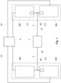
- Fig.1 shows a schematic setup to provide and set a common reference frame between the two receivers 2 and 3.
- the entangled photon source 1 is connected via two transmission channels 10 and 11 with the two receivers 2 and 3.
- Each receiver 2 and 3 comprises two measurement means.
- Receiver 2 comprises measurement means M1 and M2 and receiver 3 comprises the measurement means M3 and M4.
- Each measurement means can measure the photons of the entangled photon source in a specific measurement basis, whereas the bases of the configured setup of the receiver 2 are two mutually unbiased measurement bases B1 and B2, and the measurement bases of the receiver 3 are two mutually unbiased measurement bases B3 and B4.
- the photons in the first transmission channel 10 are randomly guided by a first separation component S1 to the first and second measurement means M1 and M2.
- the photons in the second transmission channel 11 are randomly guided by a second separation component S2 to the third and fourth measurement means M3 and M4.
- three correction means C1, C2 and C3 are arranged in three of the four measurement means.
- the correction means C1, C2 and C3 are arranged in the measurement means M2, M3 and M4.
- the correction means C1, C2 and C3 can also be in every other configuration in the measurement means.
- the correction means C1, C2 and C3 can also be in the measurement means M1, M3 and M4, or in the measurement means M1, M2 and M4, or in the measurement means M1, M2 and M3.
- the photons of the entangled photon source 1 are detected and the signal is sent via cables to a coincidence logic 4.
- the time of the arrival of each signal is registered in the coincidence logic 4, taking the distances and different cable lengths into account. From these signals, the visibility (V) and/or the quantum bit error rate (QBER) can be calculated.
- Fig. 2 shows as an example of the invention a setup of an apparatus to provide and set a common polarization reference frame between two receivers with photon pairs entangled in polarization.
- Each measurement means M1, M2, M3 and M4 can measure the photons in at least two orthogonal states.
- the entangled photon source 1 produces photon pairs entangled in polarization.
- the state of the produced entangled photon pair is in this example
- ⁇ ⁇ 1 2
- ⁇ ⁇ 1 2
- ⁇ as the states of the entangled photon pairs,
- each measurement means M1, M2, M3, and M4 a polarizing beam splitter 12 and two detectors 13. With that, each measurement means M1, M2, M3 and M4 can measure the photons in at least two orthogonal states.
- the first, second and third correction means C1, C2 and C3 are arranged.
- the correction means C1, C2 comprise a quarter wave-, half wave- and quarter wave-plate, and/or a variable wave-plate, and/or a tilted wave-plate, and/or a birefringent element, and/or a fiber controller to alter the polarization without measuring the polarization of the photons, and thus to adjust the measurement bases between the measurement means M1, M2, M3 and M4.
- Each detector 13 registers a single photon and generates an electric signal, which is sent via a cable 14 to the coincidence logic 4.
- the photons can be measured in two orthogonal states a in the first detector 13 and b in the second detector 13.
- the visibility (V) and the quantum bit error rate QBER are calculated here for photons detected in the measurement means M1 and M3, where CC M1 ⁇ ,M3 ⁇ denotes the coincidence count rate between the first detector 13 for state a in the measurement means M1, and the first detector 13 for state a in the measurement means M3.
- V M 1 , M 3 CC M 1 a , M 3 a + CC M 1 b , M 3 b ⁇ CC M 1 a , M 3 b ⁇ CC M 1 b , M 3 a CC M 1 a , M 3 a + CC M 1 b , M 3 b + CC M 1 a , M 3 b + CC M 1 b , M 3 a
- QBER M 1 , M 3 1 ⁇ V M 1 , M 3 2
- the coincidence logic 4 can be connected to the first, second and third correction means S1, S2 and S3 (the connection is not shown in Fig. 1 and 2 ) to adjust the common polarization reference frame for a secure key distribution for quantum cryptography.
- the measurement bases of measurement means M1 and M2 have to be mutually unbiased.
- the measurement means M3 and M4 have to have the same measurement bases as the measurement means in M1 and M2. According to the invention, it is not necessary for both receivers 2 and 3 to know the exact measurement bases in which they will measure the photons.
- the steps to configure the setup and to set a common polarization reference frame are:
- the steps described before can be performed in any other order. For example, at first the mutually unbiased polarization bases between the first measurement means M1 and the fourth measurement means M4 can be set, and then the same polarization bases between the first measurement means M1 and the third measurement means M3 and the same polarization bases between the fourth measurement means M4 and the second measurement means M2.
Landscapes
- Engineering & Computer Science (AREA)
- Physics & Mathematics (AREA)
- Electromagnetism (AREA)
- Computer Networks & Wireless Communication (AREA)
- Signal Processing (AREA)
- Optics & Photonics (AREA)
- Theoretical Computer Science (AREA)
- Computer Security & Cryptography (AREA)
- Optical Communication System (AREA)
Claims (14)
- Verfahren zur Bereitstellung eines gemeinsamen Bezugssystems zwischen zwei Empfängern, vorzugsweise für die Quantenschlüsselverteilung,wobei der erste Empfänger (2) über einen ersten Übertragungskanal (10) mit einer verschränkten Photonenquelle (1) verbunden ist und der zweite Empfänger (3) über einen zweiten Übertragungskanal (11) mit der verschränkten Photonenquelle (1) verbunden ist,wobei die verschränkte Photonenquelle (1) verschränkte Photonenpaare erzeugt, die vorzugsweise in der Polarisation oder in der Zeitspanne oder im Bahndrehimpuls oder im Pfad verschränkt sind,wobei das erste Photon jedes verschränkten Photonenpaares über den ersten Übertragungskanal (10) an den ersten Empfänger (2) gesendet wird und das zweite Photon jedes verschränkten Photonenpaares über den zweiten Übertragungskanal (11) an den zweiten Empfänger (3) gesendet wird,wobei der erste Empfänger (2) ein erstes (M1) und ein zweites (M2) Messmittel umfasst, um die Photonen in zwei zueinander unabhängigen Messbasen zu messen,wobei der zweite Empfänger (3) ein drittes (M3) und ein viertes (M4) Messmittel umfasst, um die Photonen in zwei zueinander unabhängigen Messbasen zu messen,wobei jedes Messmittel die Photonen in mindestens zwei orthogonalen Zuständen messen kann,wobei die vier Messmittel (M1, M2, M3, M4) den Zeitpunkt der Detektion eines Photons der verschränkten Photonenpaare kommunizieren können, um Koinzidenzen zwischen beiden Empfängern eines verschränkten Photonenpaares zu detektieren und den Kontrast und/oder die Quantenbitfehlerrate (QBER) zu berechnen,- wobei drei der vier Messmittel jeweils ein Korrekturmittel (C1, C2, C3) umfassen, um das gemeinsame Bezugssystem festzulegen,- wobei das Verfahren die folgenden Schritte umfasst:i) Minimierung der Quantenbitfehlerrate QBER oder Maximierung des Kontrasts für Photonen, die in dem ersten (M1) und dritten (M3) Messmittel detektiert werden, durch Einstellen des ersten Korrekturmittels (C1), um die gleichen Messbasen zwischen dem ersten Messmittel (M1) und dem dritten Messmittel (M3) festzulegen,ii) Maximierung der Quantenbitfehlerrate QBER oder Minimierung des Kontrasts für Photonen, die in dem ersten (M1) und vierten (M4) Messmittel detektiert werden, durch Einstellen des zweiten Korrekturmittels (C2), um zwei zueinander unabhängige Messbasen zwischen dem ersten Messmittel (M1) und dem vierten Messmittel (M4) festzulegen,iii) Minimierung der Quantenbitfehlerrate QBER oder Maximierung des Kontrasts für Photonen, die im vierten (M4) und zweiten (M2) Messmittel detektiert werden, durch Einstellen des dritten Korrekturmittels (C3), um die gleichen Messbasen zwischen dem vierten Messmittel (M4) und dem zweiten Messmittel (M2) festzulegen.
- Verfahren nach Anspruch 1,
wobei nach Schritt iii) ein sicherer Schlüssel zwischen den beiden Empfängern durch Quantenschlüsselverteilung erzeugt wird. - Verfahren nach einem der Ansprüche 1 oder 2,wobei das erste Korrekturmittel (C1) dem ersten (M1) oder dritten (M3) Messmittel zugeordnet ist, undwobei das zweite Korrekturmittel (C2) dem dritten (M3) oder vierten (M4) Messmittel zugeordnet ist, undwobei das dritte Korrekturmittel (C3) dem vierten (M4) oder zweiten (M2) Messmittel zugeordnet ist.
- Verfahren nach einem der Ansprüche 1 bis 3,wobei das erste Korrekturmittel (C1) im ersten Übertragungskanal (10) oder in oder vor dem ersten Messmittel (M1), oder im zweiten Übertragungskanal (11) oder in oder vor dem dritten Messmittel (M3) angeordnet ist, und/oderwobei das zweite Korrekturmittel (C2) im ersten Übertragungskanal (10) oder in oder vor dem ersten Messmittel (M1), oder im zweiten Übertragungskanal (11) oder in oder vor dem vierten Messmittel (M4) angeordnet ist, und/oderwobei das dritte Korrekturmittel (C3) im zweiten Übertragungskanal (11) oder in oder vor dem vierten Messmittel (M4), oder im ersten Übertragungskanal (10) oder in oder vor dem zweiten Messmittel (M2) angeordnet ist.
- Verfahren nach einem der Ansprüche 1 bis 4,
wobei die verschränkten Photonenpaare in der Polarisation oder in der Zeitspanne oder im Bahndrehimpuls oder im Pfad verschränkt sein können. - Verfahren nach einem der Ansprüche 1 bis 5,
wobei der erste (10) und/oder zweite (11) Übertragungskanal ein Freiraumkanal oder ein Wellenleiter, vorzugsweise eine Faser, ist/sind. - Verfahren nach einem der Ansprüche 1 bis 6,
wobei das erste (C1), zweite (C2) und/oder dritte (C3) Korrekturmittel ein Satz aus einer Viertelwellen-, Halbwellen- und Viertelwellenplatte, und/oder einer variablen Wellenplatte, und/oder einer gekippten Wellenplatte, und/oder einem doppelbrechenden Element, und/oder einer optischen Posaune, und/oder einem Faserregler, oder einem räumlichen Lichtmodulator (SLM) und/oder einer Verzögerungsleitung ist/sind. - Verfahren nach einem der Ansprüche 1 bis 7,wobei das Photon eines Photonenpaares im ersten Übertragungskanal (10) durch eine erste Trennkomponente (S1), vorzugsweise einen Strahlteiler oder einen Faserstrahlteiler, zufällig zum ersten (M1) oder zweiten (M2) Messmittel geführt oder durch einen Faserschalter zufällig umgeleitet wird,und/oder wobei das Photon eines Photonenpaares im zweiten Übertragungskanal (11) durch eine zweite Trennkomponente (S2), vorzugsweise durch einen Strahlteiler oder einen Faserstrahlteiler, zufällig zum dritten (M3) oder vierten (M4) Messmittel geführt oder durch einen Faserschalter zufällig umgeleitet wird.
- Verfahren nach Anspruch 8,wobei das erste Korrekturmittel (C1) nach oder hinter der ersten Trennkomponente (S1) im ersten Messmittel (M1) oder nach oder hinter der zweiten Trennkomponente (S2) im dritten Messmittel (M3) angeordnet ist, undwobei das zweite Korrekturmittel (C2) nach oder hinter der zweiten Trennkomponente (S2) in dem dritten Messmittel (M3) oder nach oder hinter der zweiten Trennkomponente (S2) in dem vierten Messmittel (M4) angeordnet ist, undwobei das dritte Korrekturmittel (C3) nach oder hinter der zweiten Trennkomponente (S2) im vierten Messmittel (M4) oder nach oder hinter der ersten Trennkomponente (S1) im zweiten Messmittel (M2) angeordnet ist.
- Steuervorrichtung (4), vorzugsweise ein Computer, die geeignet ist, ein Verfahren nach einem der Ansprüche 1 bis 9 bereitzustellen, wobei die Steuervorrichtung verbunden ist
mit dem ersten (M1), zweiten (M2), dritten (M3) und vierten (M4) Detektionsmittel, um die detektierten Photonen und die Koinzidenzen der verschränkten Photonenpaare zu registrieren und den Kontrast und/oder die Quantenbitfehlerrate der detektierten Photonen zu berechnen, und mit dem ersten (C1), zweiten (C2) und dritten (C3) Korrekturmittel, um das gemeinsame Bezugssystem zwischen den beiden Empfängern (2, 3) festzulegen. - Computereinrichtung als Steuervorrichtung nach Anspruch 10 mit einem Mikroprozessor mit einem nichtflüchtigen Speicher, wobei der nichtflüchtige Speicher ein ausführbares Programm umfasst, um ein Verfahren nach einem der Ansprüche 1 bis 9 bereitzustellen.
- System zur Bereitstellung eines gemeinsamen Bezugssystems zwischen zwei Empfängern, vorzugsweise für die Quantenschlüsselverteilung, wobei das System eine verschränkte Photonenquelle (1), einen ersten Empfänger (2) und einen zweiten Empfänger (3) sowie einen ersten Übertragungskanal (10) und einen zweiten Übertragungskanal (20) umfasst,wobei der erste Empfänger (2) über den ersten Übertragungskanal (10) mit einer verschränkten Photonenquelle (1) verbunden ist und der zweite Empfänger (3) über den zweiten Übertragungskanal (11) mit der verschränkten Photonenquelle (1) verbunden ist,wobei die verschränkte Photonenquelle (1) verschränkte Photonenpaare erzeugt, die vorzugsweise in der Polarisation oder in der Zeitspanne oder im Bahndrehimpuls oder im Pfad verschränkt sind,wobei das erste Photon jedes verschränkten Photonenpaares über den ersten Übertragungskanal (10) an den ersten Empfänger (2) gesendet wird und das zweite Photon jedes verschränkten Photonenpaares über den zweiten Übertragungskanal (11) an den zweiten Empfänger (3) gesendet wird,wobei der erste Empfänger (2) ein erstes (M1) und ein zweites (M2) Messmittel umfasst, um die Photonen in zwei zueinander unabhängigen Messbasen zu messen,wobei der zweite Empfänger (3) ein drittes (M3) und ein viertes (M4) Messmittel umfasst, um die Photonen in zwei zueinander unabhängigen Messbasen zu messen,wobei jedes Messmittel die Photonen in mindestens zwei orthogonalen Zuständen messen kann,wobei die vier Messmittel (M1, M2, M3, M4) den Zeitpunkt der Detektion eines Photons der verschränkten Photonenpaare kommunizieren können, um Koinzidenzen zwischen beiden Empfängern eines verschränkten Photonenpaares zu detektieren und den Kontrast und/oder die Quantenbitfehlerrate (QBER) zu berechnen,dadurch gekennzeichnet, dass drei der vier Messmittel jeweils ein Korrekturmittel (C1, C2, C3) umfassen, um das gemeinsame Bezugssystem festzulegen, die geeignet sind, die Schritte i) bis iii) gemäß einem der Ansprüche 1 bis 11 durchzuführen.
- System nach Anspruch 12,wobei in dem ersten Übertragungskanal (10) eine erste Trennkomponente (S1), vorzugsweise ein Strahlteiler oder ein Faserstrahlteiler, angeordnet ist, um ein Photon zufällig zu dem ersten (M1) oder zweiten (M2) Messmittel zu leiten, und/oderwobei in dem zweiten Übertragungskanal (11) eine zweite Trennkomponente (S2), vorzugsweise ein Strahlteiler oder ein Faserstrahlteiler, angeordnet ist, um ein Photon zufällig zu dem dritten (M3) oder vierten (M4) Messmittel zu leiten.
- System nach Anspruch 13,wobei das erste Korrekturmittel (C1) nach oder hinter der ersten Trennkomponente (S1) im ersten Messmittel (M1) oder nach oder hinter der zweiten Trennkomponente (S2) im dritten Messmittel (M3) angeordnet ist, undwobei das zweite Korrekturmittel (C2) nach oder hinter der zweiten Trennkomponente (S2) in dem dritten Messmittel (M3) oder nach oder hinter der zweiten Trennkomponente (S2) in dem vierten Messmittel (M4) angeordnet ist, undwobei das dritte Korrekturmittel (C3) nach oder hinter der zweiten Trennkomponente (S2) im vierten Messmittel (M4) oder nach oder hinter der ersten Trennkomponente (S1) im zweiten Messmittel (M2) angeordnet ist.
Applications Claiming Priority (2)
| Application Number | Priority Date | Filing Date | Title |
|---|---|---|---|
| EP19188171.3A EP3771137A1 (de) | 2019-07-24 | 2019-07-24 | Verfahren zur bereitstellung eines gemeinsamen referenzrahmens zwischen zwei empfängern |
| PCT/EP2020/070955 WO2021013990A1 (en) | 2019-07-24 | 2020-07-24 | Method to provide a common reference frame between two receivers |
Publications (3)
| Publication Number | Publication Date |
|---|---|
| EP4005145A1 EP4005145A1 (de) | 2022-06-01 |
| EP4005145B1 true EP4005145B1 (de) | 2024-09-04 |
| EP4005145C0 EP4005145C0 (de) | 2024-09-04 |
Family
ID=67438761
Family Applications (2)
| Application Number | Title | Priority Date | Filing Date |
|---|---|---|---|
| EP19188171.3A Withdrawn EP3771137A1 (de) | 2019-07-24 | 2019-07-24 | Verfahren zur bereitstellung eines gemeinsamen referenzrahmens zwischen zwei empfängern |
| EP20742765.9A Active EP4005145B1 (de) | 2019-07-24 | 2020-07-24 | Verfahren zur bereitstellung eines gemeinsamen referenzrahmens zwischen zwei empfängern |
Family Applications Before (1)
| Application Number | Title | Priority Date | Filing Date |
|---|---|---|---|
| EP19188171.3A Withdrawn EP3771137A1 (de) | 2019-07-24 | 2019-07-24 | Verfahren zur bereitstellung eines gemeinsamen referenzrahmens zwischen zwei empfängern |
Country Status (3)
| Country | Link |
|---|---|
| EP (2) | EP3771137A1 (de) |
| ES (1) | ES2992489T3 (de) |
| WO (1) | WO2021013990A1 (de) |
Families Citing this family (10)
| Publication number | Priority date | Publication date | Assignee | Title |
|---|---|---|---|---|
| US12039409B2 (en) | 2020-05-05 | 2024-07-16 | Qubit Moving And Storage, Llc | Quantum information system and method with entanglement tracking and generation of verified quantum information using metadata |
| US11614771B2 (en) | 2020-11-25 | 2023-03-28 | Qubit Moving And Storage, Llc | Method for synchronizing and locking clocks |
| US11962353B2 (en) | 2022-04-06 | 2024-04-16 | Qubit Moving And Storage, Llc | Method and system for identifying entangled photons with one-way classical information sharing |
| US11367014B2 (en) | 2020-05-05 | 2022-06-21 | Qubit Moving And Storage, Llc | System and method for quantum cache |
| US11616644B2 (en) | 2020-11-25 | 2023-03-28 | Qubit Moving And Storage, Llc | System and method of verification and authentication using entangled photons |
| US12003626B2 (en) | 2020-11-25 | 2024-06-04 | Qubit Moving And Storage, Llc | System and method of verification, authentication, and/or certification using entangled photons |
| US11411658B1 (en) | 2021-12-14 | 2022-08-09 | Qubit Moving And Storage, Llc | Entangled quantum state receiver |
| US11933608B2 (en) | 2022-05-19 | 2024-03-19 | Qubit Moving And Storage, Llc | Quantum interferometer with improved entangled photon identification |
| US12007272B2 (en) | 2022-10-15 | 2024-06-11 | Qubit Moving And Storage, Llc | Entangled photon identification system and method for quantum optical measurement |
| DE102023104245B3 (de) * | 2023-02-21 | 2024-06-27 | Quantum Optics Jena GmbH | Verfahren und System zur Schlüsselerzeugung mit Quantenschlüsselaustausch, sowie Verfahren zur Datenübertragung |
Family Cites Families (3)
| Publication number | Priority date | Publication date | Assignee | Title |
|---|---|---|---|---|
| US6424665B1 (en) | 1999-04-30 | 2002-07-23 | The Regents Of The University Of California | Ultra-bright source of polarization-entangled photons |
| US6897434B1 (en) | 2002-02-28 | 2005-05-24 | Northwestern University | All-fiber photon-pair source for quantum communications |
| GB2419264B (en) * | 2003-08-18 | 2006-12-27 | Toshiba Res Europ Ltd | A quantum communication system and a receiver for a quantum communication system |
-
2019
- 2019-07-24 EP EP19188171.3A patent/EP3771137A1/de not_active Withdrawn
-
2020
- 2020-07-24 ES ES20742765T patent/ES2992489T3/es active Active
- 2020-07-24 WO PCT/EP2020/070955 patent/WO2021013990A1/en not_active Ceased
- 2020-07-24 EP EP20742765.9A patent/EP4005145B1/de active Active
Also Published As
| Publication number | Publication date |
|---|---|
| EP4005145A1 (de) | 2022-06-01 |
| ES2992489T3 (es) | 2024-12-13 |
| EP3771137A1 (de) | 2021-01-27 |
| WO2021013990A1 (en) | 2021-01-28 |
| EP4005145C0 (de) | 2024-09-04 |
Similar Documents
| Publication | Publication Date | Title |
|---|---|---|
| EP4005145B1 (de) | Verfahren zur bereitstellung eines gemeinsamen referenzrahmens zwischen zwei empfängern | |
| Amer et al. | An introduction to practical quantum key distribution | |
| US8374350B2 (en) | Quantum communication system | |
| JP6303034B2 (ja) | 通信システムおよび方法 | |
| US8433070B2 (en) | Systems and methods for stabilization of interferometers for quantum key distribution | |
| US7934132B2 (en) | Communication system and method for controlling the same | |
| EP1742408B1 (de) | Kommunikationssystem und verfahren zur synchronen steuerung | |
| EP2949072B1 (de) | Quantenkryptografisches schlüsselverteilungssystem mit zwei peripherievorrichtungen und einer optischen quelle | |
| KR20190053837A (ko) | 위상 편광 다 자유도 변조 양자키분배 네트워크 시스템 및 방법 | |
| CA2883444A1 (en) | System and method for quantum key distribution | |
| EP4631192A1 (de) | Optische freiraumkommunikation mit quantenschlüsselverteilung | |
| US12362925B2 (en) | Method for remote generation of two arbitrary-length identical random cryptographic keys with the device-independent security using entangled multi- photon sources of quantum light | |
| WO2006074151A2 (en) | Secure use of a single single-photon detector in a qkd system | |
| Peranić et al. | A study of polarization compensation for quantum networks | |
| EP4062580B1 (de) | Quantenbit-decodierungsgerät, -system und -verfahren | |
| Rani et al. | Combined quantum and post-quantum security for Earth-satellite channels | |
| Mantey et al. | Frame synchronization for quantum key distribution systems | |
| Kebapci et al. | Real-time implementation of an underwater quantum key distribution system | |
| EP4005115B1 (de) | Verfahren zur einstellung eines gemeinsamen polarisationsreferenzbildes | |
| Erven | On free space quantum key distribution and its implementation with a polarization-entangled parametric down conversion source | |
| GB2441364A (en) | A quantum communication system which selects different protocols on the basis of security | |
| JP2024075947A (ja) | 量子鍵配送システム及び量子鍵配送方法 | |
| WO2026013107A1 (en) | A system for signal mode-matching for quantum key distribution setups | |
| WO2024181891A1 (ru) | Система квантовой криптографии с активным выбором базиса измерения | |
| CN110351071A (zh) | 一种发射端无需干涉环的量子密钥分发系统及方法 |
Legal Events
| Date | Code | Title | Description |
|---|---|---|---|
| STAA | Information on the status of an ep patent application or granted ep patent |
Free format text: STATUS: UNKNOWN |
|
| STAA | Information on the status of an ep patent application or granted ep patent |
Free format text: STATUS: THE INTERNATIONAL PUBLICATION HAS BEEN MADE |
|
| PUAI | Public reference made under article 153(3) epc to a published international application that has entered the european phase |
Free format text: ORIGINAL CODE: 0009012 |
|
| STAA | Information on the status of an ep patent application or granted ep patent |
Free format text: STATUS: REQUEST FOR EXAMINATION WAS MADE |
|
| 17P | Request for examination filed |
Effective date: 20220201 |
|
| AK | Designated contracting states |
Kind code of ref document: A1 Designated state(s): AL AT BE BG CH CY CZ DE DK EE ES FI FR GB GR HR HU IE IS IT LI LT LU LV MC MK MT NL NO PL PT RO RS SE SI SK SM TR |
|
| DAV | Request for validation of the european patent (deleted) | ||
| DAX | Request for extension of the european patent (deleted) | ||
| GRAP | Despatch of communication of intention to grant a patent |
Free format text: ORIGINAL CODE: EPIDOSNIGR1 |
|
| STAA | Information on the status of an ep patent application or granted ep patent |
Free format text: STATUS: GRANT OF PATENT IS INTENDED |
|
| INTG | Intention to grant announced |
Effective date: 20240522 |
|
| GRAS | Grant fee paid |
Free format text: ORIGINAL CODE: EPIDOSNIGR3 |
|
| GRAA | (expected) grant |
Free format text: ORIGINAL CODE: 0009210 |
|
| STAA | Information on the status of an ep patent application or granted ep patent |
Free format text: STATUS: THE PATENT HAS BEEN GRANTED |
|
| AK | Designated contracting states |
Kind code of ref document: B1 Designated state(s): AL AT BE BG CH CY CZ DE DK EE ES FI FR GB GR HR HU IE IS IT LI LT LU LV MC MK MT NL NO PL PT RO RS SE SI SK SM TR |
|
| REG | Reference to a national code |
Ref country code: GB Ref legal event code: FG4D |
|
| REG | Reference to a national code |
Ref country code: CH Ref legal event code: EP |
|
| REG | Reference to a national code |
Ref country code: IE Ref legal event code: FG4D |
|
| REG | Reference to a national code |
Ref country code: DE Ref legal event code: R096 Ref document number: 602020037091 Country of ref document: DE |
|
| U01 | Request for unitary effect filed |
Effective date: 20240913 |
|
| U07 | Unitary effect registered |
Designated state(s): AT BE BG DE DK EE FI FR IT LT LU LV MT NL PT RO SE SI Effective date: 20241004 |
|
| REG | Reference to a national code |
Ref country code: ES Ref legal event code: FG2A Ref document number: 2992489 Country of ref document: ES Kind code of ref document: T3 Effective date: 20241213 |
|
| PG25 | Lapsed in a contracting state [announced via postgrant information from national office to epo] |
Ref country code: NO Free format text: LAPSE BECAUSE OF FAILURE TO SUBMIT A TRANSLATION OF THE DESCRIPTION OR TO PAY THE FEE WITHIN THE PRESCRIBED TIME-LIMIT Effective date: 20241204 |
|
| PG25 | Lapsed in a contracting state [announced via postgrant information from national office to epo] |
Ref country code: PL Free format text: LAPSE BECAUSE OF FAILURE TO SUBMIT A TRANSLATION OF THE DESCRIPTION OR TO PAY THE FEE WITHIN THE PRESCRIBED TIME-LIMIT Effective date: 20240904 Ref country code: GR Free format text: LAPSE BECAUSE OF FAILURE TO SUBMIT A TRANSLATION OF THE DESCRIPTION OR TO PAY THE FEE WITHIN THE PRESCRIBED TIME-LIMIT Effective date: 20241205 |
|
| PG25 | Lapsed in a contracting state [announced via postgrant information from national office to epo] |
Ref country code: HR Free format text: LAPSE BECAUSE OF FAILURE TO SUBMIT A TRANSLATION OF THE DESCRIPTION OR TO PAY THE FEE WITHIN THE PRESCRIBED TIME-LIMIT Effective date: 20240904 |
|
| PG25 | Lapsed in a contracting state [announced via postgrant information from national office to epo] |
Ref country code: RS Free format text: LAPSE BECAUSE OF FAILURE TO SUBMIT A TRANSLATION OF THE DESCRIPTION OR TO PAY THE FEE WITHIN THE PRESCRIBED TIME-LIMIT Effective date: 20241204 |
|
| PG25 | Lapsed in a contracting state [announced via postgrant information from national office to epo] |
Ref country code: RS Free format text: LAPSE BECAUSE OF FAILURE TO SUBMIT A TRANSLATION OF THE DESCRIPTION OR TO PAY THE FEE WITHIN THE PRESCRIBED TIME-LIMIT Effective date: 20241204 Ref country code: PL Free format text: LAPSE BECAUSE OF FAILURE TO SUBMIT A TRANSLATION OF THE DESCRIPTION OR TO PAY THE FEE WITHIN THE PRESCRIBED TIME-LIMIT Effective date: 20240904 Ref country code: NO Free format text: LAPSE BECAUSE OF FAILURE TO SUBMIT A TRANSLATION OF THE DESCRIPTION OR TO PAY THE FEE WITHIN THE PRESCRIBED TIME-LIMIT Effective date: 20241204 Ref country code: HR Free format text: LAPSE BECAUSE OF FAILURE TO SUBMIT A TRANSLATION OF THE DESCRIPTION OR TO PAY THE FEE WITHIN THE PRESCRIBED TIME-LIMIT Effective date: 20240904 Ref country code: GR Free format text: LAPSE BECAUSE OF FAILURE TO SUBMIT A TRANSLATION OF THE DESCRIPTION OR TO PAY THE FEE WITHIN THE PRESCRIBED TIME-LIMIT Effective date: 20241205 |
|
| PG25 | Lapsed in a contracting state [announced via postgrant information from national office to epo] |
Ref country code: IS Free format text: LAPSE BECAUSE OF FAILURE TO SUBMIT A TRANSLATION OF THE DESCRIPTION OR TO PAY THE FEE WITHIN THE PRESCRIBED TIME-LIMIT Effective date: 20250104 |
|
| PG25 | Lapsed in a contracting state [announced via postgrant information from national office to epo] |
Ref country code: SM Free format text: LAPSE BECAUSE OF FAILURE TO SUBMIT A TRANSLATION OF THE DESCRIPTION OR TO PAY THE FEE WITHIN THE PRESCRIBED TIME-LIMIT Effective date: 20240904 |
|
| PG25 | Lapsed in a contracting state [announced via postgrant information from national office to epo] |
Ref country code: CZ Free format text: LAPSE BECAUSE OF FAILURE TO SUBMIT A TRANSLATION OF THE DESCRIPTION OR TO PAY THE FEE WITHIN THE PRESCRIBED TIME-LIMIT Effective date: 20240904 |
|
| PG25 | Lapsed in a contracting state [announced via postgrant information from national office to epo] |
Ref country code: SK Free format text: LAPSE BECAUSE OF FAILURE TO SUBMIT A TRANSLATION OF THE DESCRIPTION OR TO PAY THE FEE WITHIN THE PRESCRIBED TIME-LIMIT Effective date: 20240904 |
|
| U20 | Renewal fee for the european patent with unitary effect paid |
Year of fee payment: 6 Effective date: 20250520 |
|
| PLBE | No opposition filed within time limit |
Free format text: ORIGINAL CODE: 0009261 |
|
| STAA | Information on the status of an ep patent application or granted ep patent |
Free format text: STATUS: NO OPPOSITION FILED WITHIN TIME LIMIT |
|
| 26N | No opposition filed |
Effective date: 20250605 |
|
| PGFP | Annual fee paid to national office [announced via postgrant information from national office to epo] |
Ref country code: ES Payment date: 20250819 Year of fee payment: 6 |
|
| PGFP | Annual fee paid to national office [announced via postgrant information from national office to epo] |
Ref country code: GB Payment date: 20250724 Year of fee payment: 6 |
|
| REG | Reference to a national code |
Ref country code: CH Ref legal event code: H13 Free format text: ST27 STATUS EVENT CODE: U-0-0-H10-H13 (AS PROVIDED BY THE NATIONAL OFFICE) Effective date: 20260224 |