EP4005115B1 - Verfahren zur einstellung eines gemeinsamen polarisationsreferenzbildes - Google Patents
Verfahren zur einstellung eines gemeinsamen polarisationsreferenzbildes Download PDFInfo
- Publication number
- EP4005115B1 EP4005115B1 EP20743151.1A EP20743151A EP4005115B1 EP 4005115 B1 EP4005115 B1 EP 4005115B1 EP 20743151 A EP20743151 A EP 20743151A EP 4005115 B1 EP4005115 B1 EP 4005115B1
- Authority
- EP
- European Patent Office
- Prior art keywords
- polarization
- receiver
- emitter
- optical channel
- photons
- Prior art date
- Legal status (The legal status is an assumption and is not a legal conclusion. Google has not performed a legal analysis and makes no representation as to the accuracy of the status listed.)
- Active
Links
Images


Classifications
-
- H—ELECTRICITY
- H04—ELECTRIC COMMUNICATION TECHNIQUE
- H04B—TRANSMISSION
- H04B10/00—Transmission systems employing electromagnetic waves other than radio-waves, e.g. infrared, visible or ultraviolet light, or employing corpuscular radiation, e.g. quantum communication
- H04B10/70—Photonic quantum communication
Definitions
- the invention concerns a method to provide a common polarization reference frame between an emitter and one or two receivers and comprising an emitter and one or two receivers with a common polarization reference frame.
- the emitter comprises a source to produce polarized photons in at least two non-orthogonal polarizations or polarization entangled photon pairs
- the receiver/s comprise(s) a detection means to determine the polarization of the polarized photons in at least two non-orthogonal polarization states, wherein the emitter and receivers are connected via optical channels.
- Quantum communication for example used for quantum key distribution (QKD) known for example from " Space-to-Ground Quantum Key Distribution” Proc. Of SPIE Vol. 11180 , is using single photons for a secure and robust communication.
- QKD quantum key distribution
- SPIE Vol. 11180 Space-to-Ground Quantum Key Distribution
- a common reference frame between the emitter and the one or more receivers has to be accomplished to compensate unknown polarization-transformation introduced by the transmission channel.
- the alignment was realized by polarization controllers with feedback control known for example from " US 2009/0268276 A1 " or by a time-consuming method to ensure a common reference frame by an iteration of several alignment steps and the comparison of at least two non-orthogonal states in the emitter and the receivers.
- the typical approach is to align two basis vector sets iteratively (e.g. H horizontal and V vertical linearly polarized photons and +45° and -45° linearly polarized photons), where each iteration step affects the other basis set less.
- alignment-free transmission methods are known, for example from " Self-error-rejecting quantum state transmission of entangled photons for faithful quantum communication without calibrate reference frames" ArXiv: 1809.00105v1 .
- An objective of the present invention is to provide an improved method to set a common polarization reference between the emitter and one receiver or more receivers.
- the method to provide a common polarization reference frame between an emitter and a receiver is achieved by the method according to claim 1.
- the emitter comprises a source to produce polarized photons in at least two non-orthogonal polarizations
- the receiver comprises a detection means to determine the polarization of the polarized photons in at least two non-orthogonal polarization states, wherein the emitter and receiver are connected via an optical channel.
- the optical channel comprises a transmission means to guide the polarized photons from the emitter to the receiver, and a first correction means to correct any unitary transformation of the polarization of the photons caused by the optical channel.
- the first correction means consists of a first correction component and a second correction component, wherein the first and second correction components are separate components.
- the method comprises the steps of
- a very useful way to visualize polarization states and their transformations is the geometrical representation on the Poincaré sphere.
- a pure state corresponds to a point on the surface of the sphere with polar coordinates theta and phi.
- Polarization qubits can be conveniently detected and manipulated using only simple optical devices such as wave plates and polarizers and any unitary (coherence conserving) transformation introduced by birefringent elements can be understood as a rotation of the polarization states on the Poincaré-sphere about a particular axis.
- a key prerequisite for polarization-mode encoded quantum communication is setting and maintaining a common polarization reference frame between the emitter, preferably the source and the receiver, preferably the detection means.
- any polarization vector on the Poincaré-sphere in the source reference frame must be mapped to some known counterpart on the Poincaré-sphere at the receiver.
- the source reference frame is defined by the labeling of the axes of the non-linear crystal or a polarizer in the emitter.
- the mapping is equivalent to undoing any unitary transformation introduced from the source to the receiver and matching the computational basis polarizations (H horizontal linear polarization and V vertical linear polarization).
- a simple two-step alignment method ensures complete alignment of the entire Poincaré-sphere from transmitter to receiver without the need for iterative alignment of two mutually unbiased measurement bases.
- a logic computational basis between the emitter and the receiver is matched first with the first correction component.
- the coherent measurement basis is aligned, decoupled form the adjustment of the logic computational basis.
- the alignment of the first step ensures that the first basis is set between the emitter and the receiver, and is ambiguous with respect to the relative phase phi.
- This transformation can be understood as a rotation of the Poincaré-sphere, for example about the axis combining H and V.
- This remaining Poincaré-sphere transformation is adjusted in the manner that does not introduce an additional rotation of the first basis (as an example here the H/V basis), by introducing only an additional relative variable phase between the basis vectors of the polarization basis used for the alignment in the first step.
- This can be achieved, for example, using a tilted wave-plate, a quarter-wave/half-wave/quarter-wave combination, a Soleil Babinet Compensator that introduces only a relative phase.
- the object of the invention is also achieved by an apparatus to provide a common reference frame between an emitter and one receiver in at least two non-orthogonal polarization states, wherein the emitter comprises a source to produce polarized photons in at least two non-orthogonal polarizations adapted to perform step I), and wherein the receiver comprises a detection means to determine the polarization of the polarized photons in at least two non-orthogonal polarization states, and wherein the emitter and receiver are connected via an optical channel comprising a transmission means to guide the polarized photons from the emitter to the receiver, and a first correction means to correct any unitary transformation of the polarization of the photons caused by the optical channel, and wherein the first correction means consists of at least two separate components, a first correction component adapted to perform step II) and a second correction component adapted to perform step III).
- the first and/or the second correction component of the first correction means comprises a variable wave-plate, or a tilted wave-plate, or a Philadelphia Babinet compensator, or a combination of a first quarter wave-plate, a half wave-plate, and a second quarter-wave plate, or a fiber controller creating the behavior of a first quarter wave-plate, a half wave-plate, and a second quarter-wave plate by a first, second, and third spools of the fiber, or a rotatable fiber squeezer.
- the local polarization reference means comprises one of a polarizing means, or a polarizing beam splitter, or a polarizer, or down converted photons, or a non-linear crystal, or a laser producing polarized photons.
- the local polarization reference means comprise in addition an optical element to change the polarization of the photons in at least two non-orthogonal polarizations, preferably a wave plate.
- the calibration step of the first correction component is performed in order to compensate the unitary transformation of the first emitter polarization state caused by the optical channel.
- the calibration step of the second correction component is performed in order to compensate the unitary transformation of the second emitter polarization state caused by the optical channel.
- each receiver can measure the photons in at least two orthogonal states in its non-orthogonal basis.
- the transmission channel is a free-space channel, preferably air or vacuum or any other atmosphere or a liquid.
- the first correction component of the first correction means comprises a variable wave-plate, or a tilted wave-plate, or a Babinet-soleil compensator, or a combination of a first quarter wave-plate, a half wave-plate, and a second quarter-wave plate.
- the second correction component of the first correction means comprises a variable wave-plate, or a tilted wave-plate, or a Babinet-soleil compensator, or a combination of a first quarter wave-plate, a half wave-plate, and a second quarter-wave plate.
- the transmission channel is the wave guide, preferably a fiber.
- the transmission means comprises two coupling means and a waveguide, preferably a fiber, connecting the two coupling means, wherein the first coupling means couples the photons from the emitter into the fiber and the second coupling means couples the photons out of the fiber into the first receiver.
- the first correction component of the first correction means comprises a first quarter wave-plate, and a half wave-plate, and a second quarter-wave plate, before the first coupling means or after the second coupling means, or a fiber controller creating the behavior of a first quarter wave-plate, a half wave-plate, and a second quarter-wave plate by a first, second, and third spools, of the fiber or a rotatable fiber squeezer in the fiber.
- the second correction component of the first correction means comprises a variable wave-plate, or a tilted wave-plate, or a Philadelphia Babinet compensator, or a combination of a first quarter wave-plate, a half wave-plate, and a second quarter-wave plate, before the first coupling means or after the second coupling means, or a fiber controller creating the behavior of a first quarter wave-plate, a half wave-plate, and a second quarter-wave plate by a first, second, and third spools of the fiber, or a rotatable fiber squeezer in the fiber.
- the first or the second emitter polarization state is a linear horizontal/vertical, or linear 45°/-45° polarization or left/right circular polarization.
- the local reference frame can for example be set with a polarizer. Sending horizontal polarized photons (H) from the emitter to the receivers, the detected events at the receiver in the corresponding vertical (V) detector should be minimized by the first correction means. Subsequently, diagonal polarized photons (D) are transmitted to the receiver and the corresponding detected events at the receiver in the corresponding antidiagonal (A) detector should be minimized by the second correction means.
- the common polarization reference frame is provided between an emitter and two receivers, wherein the emitter is a laser or a photon source producing polarized photons in at least two non-orthogonal polarizations, and wherein the first receiver comprises a first detection means to determine the polarization of the polarized photons in at least two non-orthogonal polarization stats, and the second receiver comprises a second detection means to determine the polarization of the polarized photons in at least two non-orthogonal polarization states.
- the common polarization reference frame is provided between an emitter and two receivers, wherein the emitter comprises a laser or a photon source producing polarization photons in at least two non-orthogonal polarizations adapted to perform step I), wherein the first receiver comprises a first detection means to determine the polarization of the polarized photons in at least two non-orthogonal polarization states and the second receiver comprises a second detection means to determine the polarization of the polarized photons in at least two non-orthogonal polarization states, wherein the laser or the photon source and the first receiver are connected via a first optical channel comprising a first transmission means to guide the polarized photons from the emitter to the first receiver, and a first correction means to correct any unitary transformation of the polarization of the photons caused by the first optical channel, and wherein the laser or the photon source and the second receiver are connected via a second optical channel comprising a second transmission means to guide the
- the first and/or the second correction component of the first and/or the second correction means comprises a variable wave-plate, or a tilted wave-plate, or a Philadelphia Babinet compensator, or a combination of a first quarter wave-plate, a half wave-plate, and a second quarter-wave plate, or a fiber controller creating the behavior of a first quarter wave-plate, a half wave-plate, and a second quarter-wave plate by a first, second, and third spools of the fiber, or a rotatable fiber squeezer in the fiber.
- the local polarization reference means comprises one of a polarizing means, or a polarizing beam splitter, or a polarizer, or down converted photons, or a non-linear crystal, or a laser producing polarized photons.
- the local polarization reference means comprises in addition an optical element to change the polarization of the photons in at least two non-orthogonal polarizations, preferably a wave plate.
- the first or the second emitter polarization state is a linear horizontal/vertical, or linear 45°/-45° polarization or left/right circular polarization.
- the calibration step of the first correction component of the first correction means is performed in order to compensate the unitary transformation of the first emitter polarization state caused by the first optical channel.
- the calibration step of the first correction component of the second correction means is performed in order to compensate the unitary transformation of the first emitter polarization state caused by the second optical channel.
- the calibration step of the second correction component of the first correction means is performed in order to compensate the unitary transformation of the second emitter polarization state caused by the first optical channel.
- the calibration step of the second correction component of the second correction means is performed in order to compensate the unitary transformation of the second emitter polarization state caused by the second optical channel.
- each receiver can measure the photons in at least two orthogonal states in its non-orthogonal basis.
- the photon source is an entangled photon source producing polarization entangled photon pairs, wherein one photon of each entangled photon pair is sent in the first optical channel to the first receiver and the second photon of each entangled photon pair is sent in the second optical channel to the second receiver.
- the method comprises the further steps of
- the local polarization reference frame in step I) is set by a polarizing beam splitter, or a polarizer, or the polarization of a down converted photon, or the axes of a non-linear crystal, and the propagation of the photon beam through this optical component, or is set by the detection means of the first receiver comprising a polarizing beam splitter, or a polarizer.
- the first and/or second transmission channel is/are free-space channel/s, preferably air or vacuum or any other atmosphere or a liquid.
- the first correction component of the first and/or second correction means comprises a variable wave-plate, or a tilted wave-plate, or a Babinet-soleil compensator, or a combination of a first quarter wave-plate, a half wave-plate, and a second quarter-wave plate.
- the second correction component of the first and/or second correction means comprises a variable wave-plate, or a tilted wave-plate, or a Babinet-soleil compensator, or a combination of a first quarter wave-plate, a half wave-plate, and a second quarter-wave plate.
- the transmission channel is a wave guide, preferably a fiber.
- the first and/or second optical channel comprises two coupling means and a waveguide, preferably a fiber, connecting the two coupling means, wherein the first coupling means couples the photons from the emitter into the fiber and the second coupling means couples the photons out of the fiber into the first and/or second receiver.
- the first correction component of the first and/or second correction means comprises a first quarter wave-plate, and a half wave-plate, and a second quarter-wave plate, before the first coupling means or after the second coupling means, or a fiber controller creating the behavior of a first quarter wave-plate, a half wave-plate, and a second quarter-wave plate by a first, second, and third spools, of the fiber or a rotatable fiber squeezer in the fiber.
- the second correction component of the first and/or second correction means comprises a variable wave-plate, or a tilted wave-plate, or a Philadelphia Babinet compensator, or a combination of a first quarter wave-plate, a half wave-plate, and a second quarter-wave plate, before the first coupling means or after the second coupling means, or a fiber controller creating the behavior of a first quarter wave-plate, a half wave-plate, and a second quarter-wave plate by a first, second, and third spools of the fiber, or a rotatable fiber squeezer in the fiber.
- the object of the invention is also achieved by a method to provide an emitter and two receivers with a common polarization reference frame according to claim 7.
- the emitter is an entangled photon source, producing polarization entangled photon pairs
- the first receiver comprises a first detection means to determine the polarization of the polarized photons in at least two non-orthogonal polarization states
- the second receiver comprises a second detection means to determine the polarization of the polarized photons in at least two non-orthogonal polarization states
- a first optical channel connecting the emitter and the first receiver, comprising a first transmission means to guide the polarized photons from the emitter to the first receiver, and a second optical channel, connecting the emitter and the second receiver, comprising a second transmission means to guide the polarized photons from the emitter to the second receiver, and wherein one photon of each entangled photon pair is sent in the first optical channel to the first receiver and the second photon of each entangled photo
- entangled photons can be produced via numerous schemes by an entangled photon source, for example by spontaneous parametric down-conversion in a non-linear crystal.
- the unique quantum feature of such entangled Bell states is that they also exhibit correlations in other measurement bases.
- the photon pairs In order to exploit the polarization correlations, for example, in quantum information processing, the photon pairs must be transmitted to the first and second receivers (Alice and Bob) in a transmission channel. One or both transmission channels can introduce a transformation of the polarization reference frame.
- the emitter and the first and second receivers (Alice and Bob) must set a common polarization reference frame.
- common polarization reference frame in the emitter and both receivers for example, the nonlocal correlations in the entangled state can be verified, exploited and used.
- a very useful way to visualize polarization states and their transformations is the geometrical representation on the Poincaré sphere.
- a pure state corresponds to a point on the surface of the sphere with polar coordinates theta and phi.
- Polarization qubits can be conveniently detected and manipulated using only simple optical devices such as wave plates and polarizers and any unitary (coherence conserving) transformation introduced by birefringent elements can be understood as a rotation of the polarization states on the Poincaré-sphere about a particular axis.
- a key prerequisite for polarization-mode encoded quantum communication is setting and maintaining a common polarization reference frame between the emitter, preferably the source and the receivers, preferably the detection means.
- any polarization vector on the Poincaré-sphere in the source reference frame must be mapped to some known counterpart on the Poincaré-sphere at the receivers.
- the source reference frame is defined by the labeling of the axes of the non-linear crystal or a polarizer in the emitter.
- the mapping is equivalent to undoing any unitary transformation introduced from the source to the receivers and matching the computational basis polarizations (H horizontal linear polarization and V vertical linear polarization).
- a simple two-step alignment method ensures complete alignment of the entire Poincaré-sphere from transmitter to receivers without the need for iterative alignment of two mutually unbiased measurement bases.
- a logic computational basis between the emitter and the receivers is matched first with the first correction component.
- the coherent measurement basis is aligned, decoupled from the adjustment of the logic computational basis.
- the alignment of the first step ensures that the first basis is set between the emitter and the receivers, and is ambiguous with respect to the relative phase phi.
- This transformation can be understood as a rotation of the Poincaré-sphere, for example about the axis combining H and V.
- This remaining Poincaré-sphere transformation is adjusted in the manner that does not introduce an additional rotation of the first basis (as an example here the H/V basis), by introducing only an additional relative variable phase between the basis vectors of the polarization basis used for the alignment in the first step.
- This can be achieved, for example, using a tilted wave-plate, a quarter-wave/half-wave/quarter-wave combination, a Soleil Babinet Compensator that introduces only a relative phase with respect to the H/V basis of the entangled photon source, or a polarizer or polarizing beam splitter in the receiver.
- this phase can also be absorbed into the phase of the entangled photon generation.
- the common polarization reference frame is provided between an emitter and two receivers, wherein the emitter comprises an entangled photon source adapted to perform step I), wherein the first receiver comprises a first detection means to determine the polarization of the polarized photons in at least two non-orthogonal polarization states and the second receiver comprises a second detection means to determine the polarization of the polarized photons in at least two non-orthogonal polarization states, and a first optical channel, connecting the emitter and the first receiver, comprising a first transmission means to guide the polarized photons from the emitter to the first receiver, and a second optical channel, connecting the emitter and the second receiver, comprising a second transmission means to guide the polarized photons from the emitter to the second receiver, and wherein one photon of each entangled photon pair is sent in the first optical channel to the first receiver and the second photon of each entangled photon pair is sent in the second optical channel to the second
- the first and/or the second correction component of the first and/or the second correction means comprises a variable wave-plate, or a tilted wave-plate, or a Philadelphia Babinet compensator, or a combination of a first quarter wave-plate, a half wave-plate, and a second quarter-wave plate, or a fiber controller creating the behavior of a first quarter wave-plate, a half wave-plate, and a second quarter-wave plate by a first, second, and third spools of the fiber, or a rotatable fiber squeezer in the fiber or the first and/or the second correction component is realized by changing the pump polarization of the entangled photon source.
- the local polarization reference means comprises one of a polarizing means, or a polarizing beam splitter, or a polarizer, or down converted photons, or a non-linear crystal.
- the calibration step of the first correction component of the first correction means is performed in order to compensate the unitary transformation of the first emitter polarization state caused by the first and/or second optical channel.
- the calibration step of the first correction component of the second correction means is performed in order to compensate the unitary transformation of the first emitter polarization state caused by the first and/or second optical channel.
- the calibration step of the second correction component of the first correction means is performed in order to compensate the unitary transformation of the second emitter polarization state caused by the first and/or second optical channel.
- the calibration step of the second correction component of the second correction means is performed in order to compensate the unitary transformation of the second emitter polarization state caused by the first and/or second optical channel.
- the local polarization reference frame in step I) is set by the polarization of down converted photons, or the axes of a non-linear crystal, and the propagation of the photons through this optical component, or by a polarizing beam splitter in a Sagnac entangled photon source.
- the emitter comprises the entangled photon source and one or two coupling means with a first part of a waveguide.
- the transmission means consist of the remaining waveguide to the receivers.
- the coupling means and a part of the waveguides are part of the emitter, preferably parts of the entangled photon source. This allows, for example, that the first correction component in the emitter can be arranged in the waveguide and the second correction component in the emitter can be arranged in the entangled photon source.
- the first and/or second transmission channel is/are a free-space channel/s, preferably air or vacuum or any other atmosphere or a liquid.
- the first correction component of the first and/or second correction means comprises a first quarter wave-plate, a half wave-plate, and a second quarter-wave plate or is realized by changing the pump polarization of the entangled photon source.
- the second correction component of the first and/or second correction means comprises a variable wave-plate, or a tilted wave-plate, or a Babinet-soleil compensator, or a combination of a first quarter wave-plate, a half wave-plate, and a second quarter-wave plate or is realized by changing the pump polarization of the entangled photon source.
- the transmission channel is a wave guide, preferably a fiber.
- the first and/or second optical channel comprises one coupling means and a waveguide, preferably a fiber, connecting the optical channel to the first and/or second receiver, wherein the first coupling means couples the photons from the emitter into the fiber.
- the first and/or second optical channel comprises two coupling means and waveguide, preferably a fiber, connecting the two coupling means, wherein the first coupling means couples the photons from the emitter into the fiber and the second coupling means couples the photons out of the fiber into the first and/or second receiver.
- the first correction component of the first and/or second correction means comprises a first quarter wave-plate, and a half wave-plate, and a second quarter-wave plate, before the first coupling means or after the second coupling means, or a fiber controller creating the behavior of a first quarter wave-plate, a half wave-plate, and a second quarter-wave plate by a first, second, and third spools, of the fiber or a rotatable fiber squeezer in the fiber or is realized by changing the pump polarization of the entangled photon source.
- the second correction component of the first and/or second correction means comprises a variable wave-plate, or a tilted wave-plate, or a Philadelphia Babinet compensator, or a combination of a first quarter wave-plate, a half wave-plate, and a second quarter-wave plate, before the first coupling means or after the second coupling means, or a fiber controller creating the behavior of a first quarter wave-plate, a half wave-plate, and a second quarter-wave plate by a first, second, and third spools of the fiber, or a rotatable fiber squeezer in the fiber or is realized by changing the pump polarization of the entangled photon source.
- the first or the second emitter polarization state is a linear horizontal/vertical, or linear 45°/-45° polarization or left/right circular polarization.
- the local reference frame can also be set by a polarizing beam splitter in a Sagnac loop source, producing entangled photons or by pumping the photon source to produce, for example, only HH photons.
- These polarization measurements are performed using polarizers in the transmission channels. For example, the maximally-entangled Psi- state exhibits anti-correlation in any measurement basis.
- the first correction component of the first and/or second correction means has to be set to detect a minimum of coincidence counts (two-photon detection events of photon pairs).
- the local polarization measurement is changed to another measurement basis in the local reference frame, a non-orthogonal state to the first H/H polarization state.
- a minimum of coincidence counts two-photon detection events of photon pairs
- This is also expected for measurement in the 45°/-45° measurement basis (with 45° as linear polarization at 45° and -45° as linear polarization at -45°).
- This is also expected for left and right circular polarization.
- This can be achieved by changing the pump polarization of the entangled photon source, specifically the relative phase phi between the horizontal and vertical pump photon components.
- a second correction means comprising a variable wave-plate, or a tilted wave-plate, or a Philadelphia Babinet compensator, or a combination of a first quarter wave-plate, a half wave-plate, and a second quarter-wave plate, before the first coupling means or after the second coupling means, or a fiber controller creating the behavior of a first quarter wave-plate, a half wave-plate, and a second quarter-wave plate by a first, second, and third spools of the fiber, or a rotatable fiber squeezer in the fiber.
- the alignment of the first step has ensured in this example that the first basis is set between the emitter and the receivers, and is ambiguous with respect to the relative phase phi.
- This transformation can be understood as a rotation of the Poincaré-sphere about the axis combining H and V.
- This remaining Poincaré-sphere transformation is adjusted in the manner that does not introduce an additional rotation of the H/V basis, by introducing only an additional relative variable phase between the basis vectors of the polarization basis used for the alignment in the first step.
- this phase can also be absorbed into the phase of the entangled photon generation.
- the common reference frame can be set with any other entangled state taking the correlations or anti-correlations of the specific stats for any measurement basis into account.
- control device adapted to provide and capable of providing a method according to one the methods described above with one receiver, wherein the control device is connected with the first correction means and with the first detection means, and preferably with the local polarization reference means.
- control device adapted to provide and capable of providing a method according to one of the methods described above with two receivers, wherein the control device is connected with the first and/or second correction means and with the first and/or second detection means, and preferably with the local polarization reference means.
- the object of the invention is in addition achieved by a computer device with a microprocessor with a nonvolatile memory, wherein the nonvolatile memory comprises an executable program in order to provide a method according to one of the methods described above, preferably wherein the computer device is the control device.
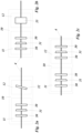
- Fig. 1a shows a schematic setup for an emitter 1 connected via a first transmission means 4 with a first receiver 2.
- the emitter 1 produces polarized photons and sets a local polarized reference frame in at least two non-orthogonal or complementary polarization states.
- the polarized photons are transmitted in the first transmission means 4 to the first receiver 2.
- the first receiver 2 can measure the photons in at least two non-orthogonal polarization states.
- a first correction means 10 is arranged in the first transmission means 4 to correct any unitary transformation of the polarization of the photons caused by the first transmission means 4.
- the first correction means 10 comprises a first correction component 11 and a second correction component 12. Both correction components 11 and 12 can be used independently to set the common reference frame in the emitter 1 and the first receiver 2 independently for the first and the second non-orthogonal state.
- the first correction component 11 is used to set the first non-orthogonal state of the emitter 1 in the first receiver 2
- the second correction component 12 is used to set the second non-orthogonal state of the emitter 1 in the first receiver 2.
- Fig. 1b shows a schematic setup for an emitter 1 connected via a first transmission means 4 with a first receiver 2 and via a second transmission means 5 with a second receiver 3.
- Fig. 1b differs from Fig. 1a only in that in the second transmission means 5, a second correction means 20 is arranged, comprising a first correction component 21 and a second correction component 22.
- the second correction means 20 is arranged in the second transmission means 5 to compensate any unitary transformation in at least two non-orthogonal states by the second transmission means 5.
- Both correction components 21 and 22 can be used independently to set the common reference frame in the emitter 1 and the second receiver 3 independently for the first and the second non-orthogonal state.
- the emitter 1 in Fig. 1b is an entangled photon source producing photon pairs entangled in the polarization.
- the first photon of each entangled photon pair is sent via the first transmission channel 4 to the first receiver 2 and the second photon of each entangled photon pair is sent via the second transmission channel 5 to the second receiver 3.
- the simple two-step alignment method from Fig. 1a has to be performed for the first receiver 2 with the first correction means 10, and a second time for the second receiver 3 with the second correction means 20.
- Fig. 2a shows a first inventive configuration of the first correction means 10 in the first transmission means 4.
- the first correction component 11 comprises a first quarter wave-plate 30, a half wave-plate 31, and a second quarter-wave plate 30.
- the second correction component comprises a tilted wave-plate 32.
- Fig. 2b shows a second inventive configuration of the correction means 10 in the first transmission means 4.
- the second correction component 12 comprises a Babinet compensator 33.
- Fig. 2c shows a third inventive configuration of the correction means 10 in the first transmission means 4.
- the second correction component 12 comprises a first quarter wave-plate 30, a half wave-plate 31, and a second quarter-wave plate 30.
- All inventive examples of the Fig. 2a to 2c can also be implemented as the second correction means 20. It is also possible to use a variable wave-plate as a second correction component 12.
- Fig. 3 shows a setup for providing a common reference frame between the emitter 1 and two receivers 2 and 3.
- the emitter 1 is an entangled photon source 40, here as an example in a type-0 SPDC process, a high energy pump photon, emitted from a laser 42 on the first photon path 43 with polarization H, can produce a pair of photons HH with lower energy traveling on the second photon path 44 to coupling means 45.
- H denotes some particular optical axis with respect to the nonlinear photon pair source.
- the two transmission channels 4 and 5 guide the photons to the first receiver 2, in the following called Alice, and to the second receiver 3, in the following called Bob.
- Alice 2 and Bob 3 each have a detection means, preferably a polarization analyzer that detects the polarization of single photons.
- the detection means, preferably the polarization analyzer can consist of a polarizing beam splitter cube and a number of wave-plates to perform polarization measurements for arbitrary polarization states, and is shown in detail in Fig. 6.
- the unique quantum feature of such entangled Bell states is that they also exhibit correlations in other measurement bases.
- the photon pairs In order to exploit the polarization correlations in quantum information processing, the photon pairs must be transmitted to distant measurement sites (Alice 2 and Bob 3). Since the transmission channel can introduce a transformation of the polarization reference frames, Alice 2 and Bob 3 and the entangled photon source 40 must set a common polarization reference frame to verify and exploit the nonlocal correlations present in the entangled state
- the alignment procedure comprises the following steps: The entangled photon source is aligned and calibrated to produce a particular polarization-entangled state in the local reference frame, as defined for example by the axes of the non-linear crystal 41, or the Polarizing beam splitter in a Sagnac loop source of entangled photons. The polarization correlations that reflect a particular Bell state are then ensured in the local measurement basis. The measurements of theses polarization correlations are performed using calibrated thin film polarizers 49, inserted before the first and second transmission channels 4 and 5.
- the maximally-entangled Phi+ state exhibits correlation in any measurement basis.
- the coincidence detection is the detection of two photons in the coincidence window. For that, the detectors (not shown in Fig.
- the coincidence logic 50 which counts a coincidence when two photons, one in each receiver 2 and 3, are detected at the same time, taking different distances and cable lengths into account. I.e., when the two thin film polarizers are in parallel, there should be a minimum of two-photon detection events registered by single-photon detectors located in the first and second receivers 2 and 3.
- This first step is realized for the emitter 1 and the first and second receivers 2 and 3, with the first correction component 11 of the first correction means 10 and/or the first correction component 21 of the second correction means 20.
- the local polarization measurements are changed to another measurement basis in the local reference frame.
- a maximum or minimum of two-photon detection events is also expected for measurements in a non-orthogonal state measurement basis. This can be achieved by changing the pump polarization, specifically the relative phase phi between the horizontal and vertical pump photon components (which drive the two SPDC possibilities).
- the alignment of the HV basis in step (I) has ensured that HV or VH coincidence detection of photon pairs is minimized, or the joint detection probability for HH or VV coincidence detection of photon pairs is maximized, and is ambiguous with respect to the relative phase phi.
- This transformation can be understood as a rotation of the Poincaré-sphere about the axis combining H and V.
- This remaining Poincaré-sphere transformation is adjusted in a manner that does not introduce an additional rotation of the HV basis, by introducing only an additional relative variable phase between the basis vectors of the polarization basis used for the alignment in step (I).
- the second correction component 12 of the first correction means 10 and/or the second correction 22 of the second correction means 20 for example by first quarter wave-plate 30, a half wave-plate 31, and a second quarter-wave plate 30, or a tilted wave-plate 32, or a Soleil Babinet Compensator that introduces only a relative phase with respect to the HV basis of either the entangled photon source (non-linear crystal axis), or the polarizing beam splitter of the detection means. In the case of a polarization-entangled photon source, this phase can also be absorbed into the phase of the entangled photon generation.
- an entangled photon source in Sagnac configuration is also possible.
- These entangled photon sources are well known.
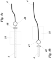
- Fig. 4 shows different positions of the correction means 10 for a first transmission channel 4, comprising a free-space transmission section and a fiber transmission section connected via a coupling means 45.
- the correction means 10 can be arranged in the free-space transmission section ( Fig. 4a ) or in the fiber transmission section ( Fig. 4b ).
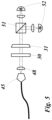
- Fig. 5 shows a possible variant of a detection means, preferably a polarization analyzer for a first and/or second receiver 2 and/or 3. It can consist of a polarizing beam splitter 51, a half-wave plate 30, and a quarter-wave plate 31 to perform polarization measurements for arbitrary polarization states.
- a detection means preferably a polarization analyzer for a first and/or second receiver 2 and/or 3. It can consist of a polarizing beam splitter 51, a half-wave plate 30, and a quarter-wave plate 31 to perform polarization measurements for arbitrary polarization states.
Landscapes
- Physics & Mathematics (AREA)
- Optics & Photonics (AREA)
- Electromagnetism (AREA)
- Engineering & Computer Science (AREA)
- Computer Networks & Wireless Communication (AREA)
- Signal Processing (AREA)
- Optical Communication System (AREA)
Claims (15)
- Verfahren zum Bereitstellen eines Emitters (1) und eines Empfängers (2) mit einem gemeinsamen Polarisationsreferenzrahmen,wobei der Emitter (1) eine Quelle zur Erzeugung von polarisierten Photonen in mindestens zwei nicht-orthogonalen Polarisationen umfasst,wobei der Empfänger (2) ein Detektionsmittel zur Bestimmung der Polarisation der polarisierten Photonen in mindestens zwei nicht-orthogonalen Polarisationszuständen umfasst,wobei der Emitter (1) und der Empfänger (2) über einen optischen Kanal verbunden sind,wobei der optische Kanal ein Übertragungsmittel (4) umfasst, um die polarisierten Photonen vom Emitter zum Empfänger zu leiten, und eine erste Korrektureinrichtung (10), um jede durch den optischen Kanal verursachte unitäre Transformation der Polarisation der Photonen zu korrigieren,wobei die erste Korrektureinrichtung (10) aus einer ersten Korrekturkomponente (11) und einer zweiten Korrekturkomponente (12) besteht, wobei die erste und die zweite Korrekturkomponente (11, 12) separate Komponenten sind,wobei das Verfahren die Schritte umfasst:I) Bereitstellen eines lokalen Polarisationsreferenzrahmens mit einem lokalen Polarisationsreferenzmittel in dem Emitter (1) mit mindestens zwei nicht orthogonalen Polarisationszuständen, einem ersten lokalen Polarisationsreferenzzustand und einem zweiten lokalen Polarisationsreferenzzustand,II) Durchführen eines oder mehrerer Kalibrierungsschritte durch Anpassen der ersten Korrekturkomponente (11) der Korrektureinrichtung (10) und Maximieren und/oder Minimieren der detektierten Photonen in den Detektionsmitteln in dem Empfänger in dem ersten Referenzpolarisationszustand, um den ersten lokalen Polarisationsreferenzzustand in dem Empfänger einzustellen,III) Durchführen eines oder mehrerer Kalibrierungsschritte durch Anpassen der zweiten Korrekturkomponente (12) der Korrektureinrichtung (10) und Maximieren und/oder Minimieren der detektierten Photonen in den Detektionsmitteln in dem Empfänger in dem zweiten Referenzpolarisationszustand, um den zweiten lokalen Polarisationsreferenzzustand in dem Empfänger einzustellen.
- Verfahren nach Anspruch 1,
wobei die erste und/oder die zweite Korrekturkomponente (11, 12) der ersten Korrektureinrichtung (10) eine variable Wellenplatte oder eine gekippte Wellenplatte oder einen Soleil-Babinet-Kompensator oder eine Kombination aus einem ersten λ/4-Plättchen, einem λ/2-Plättchenund einem zweiten λ/4-Plättchenoder eine Fasersteuerung, die das Verhalten eines ersten λ/4-Plättchens, eines λ/2-Plättchens und eines zweiten λ/4-Plättchensdurch eine erste, zweite und dritte Spule der Faser erzeugt, oder einen drehbaren Faserquetscher umfasst. - Verfahren nach einem der Ansprüche 1 oder 2,
wobei das lokale Polarisationsreferenzmittel eines der folgenden Mittel umfasst: ein polarisierendes Mittel oder einen polarisierenden Strahlteiler oder einen Polarisator oder abwärts konvertierte Photonen oder einen nicht-linearen Kristall oder einen Laser, der polarisierte Photonen erzeugt. - Verfahren zum Bereitstellen eines Emitters (1) und zweier Empfänger (2, 3) mit einem gemeinsamen Polarisationsreferenzrahmen,wobei der Emitter (1) ein Laser (42) oder eine Photonenquelle zur Erzeugung von polarisierten Photonen in mindestens zwei nicht-orthogonalen Polarisationen ist, undwobei der erste Empfänger (2) ein erstes Detektionsmittel umfasst, um die Polarisation der polarisierten Photonen in mindestens zwei nicht-orthogonalen Polarisationszuständen zu bestimmen, und der zweite Empfänger (3) ein zweites Detektionsmittel umfasst, um die Polarisation der polarisierten Photonen in mindestens zwei nicht-orthogonalen Polarisationszuständen zu bestimmen, undwobei ein erster optischer Kanal den Emitter und den ersten Empfänger verbindet, wobei er ein erstes Übertragungsmittel (4) umfasst, um die polarisierten Photonen von dem Emitter (1) zu dem ersten Empfänger (2) zu leiten, und wobei ein zweiter optischer Kanal den Emitter (1) und den zweiten Empfänger (3) verbindet, wobei er ein zweites Übertragungsmittel (5) umfasst, um die polarisierten Photonen von dem Emitter (1) zu dem zweiten Empfänger (3) zu leiten, undwobei der erste optische Kanal eine erste Korrektureinrichtung (10) umfasst, um jede durch den ersten optischen Kanal verursachte unitäre Transformation der Polarisation der Photonen zu korrigieren, und/oder wobei der zweite optische Kanal eine zweite Korrektureinrichtung (20) umfasst, um jede durch den zweiten optischen Kanal verursachte unitäre Transformation der Polarisation der Photonen zu korrigieren, undwobei die erste und/oder zweite Korrektureinrichtung (10, 20) jeweils aus einer ersten Korrekturkomponente (11, 21) und einer zweiten Korrekturkomponente (12, 22) besteht, undwobei der Emitter (1) polarisierte Photonen in dem ersten optischen Kanal zu dem ersten Empfänger (2) und in dem zweiten optischen Kanal zu dem zweiten Empfänger (3) sendet,wobei die Kalibrierung des gemeinsamen Polarisationsreferenzrahmens zwischen dem Emitter (1) und dem ersten und/oder zweiten Empfänger (2, 3) oder zwischen dem ersten und dem zweiten Empfänger (2, 3) nach einem der Ansprüche 1 bis 3 erfolgt.
- Verfahren nach Anspruch 4,wobei die Photonenquelle eine verschränkte Photonenquelle ist, die polarisationsverschränkte Photonenpaare erzeugt,wobei ein Photon jedes verschränkten Photonenpaares über den ersten optischen Kanal an den ersten Empfänger (2) und das zweite Photon jedes verschränkten Photonenpaares über den zweiten optischen Kanal an den zweiten Empfänger (3) gesendet wird.
- Verfahren nach Anspruch 5, wobei das Verfahren die folgenden weiteren Schritte umfasst:IV) Durchführen eines oder mehrerer Kalibrierungsschritte durch Anpassen der ersten Korrekturkomponente (11, 21) der ersten und/oder zweiten Korrektureinrichtung (10, 20) und Maximieren und/oder Minimieren der Korrelationen der verschränkten Photonenpaare im ersten Emitterpolarisationszustand, um den ersten lokalen Polarisationszustand im ersten und/oder zweiten Empfänger einzustellen, und/oderV) Durchführen eines oder mehrerer Kalibrierungsschritte durch Anpassen der zweiten Korrekturkomponente (12, 22) der ersten und/oder zweiten Korrektureinrichtung (10, 20) und Maximieren und/oder Minimieren der Korrelationen der verschränkten Photonenpaare im zweiten Emitterpolarisationszustand, um den zweiten lokalen Polarisationszustand im ersten und/oder zweiten Empfänger einzustellen.
- Verfahren zum Bereitstellen eines Emitters (1) und zweier Empfänger (2, 3) mit einem gemeinsamen Polarisationsreferenzrahmen,wobei der Emitter (1) eine verschränkte Photonenquelle ist, die polarisationsverschränkte Photonenpaare erzeugt, undwobei der erste Empfänger (2) ein erstes Detektionsmittel umfasst, um die Polarisation der polarisierten Photonen in mindestens zwei nicht-orthogonalen Polarisationszuständen zu bestimmen, und der zweite Empfänger (3) ein zweites Detektionsmittel umfasst, um die Polarisation der polarisierten Photonen in mindestens zwei nicht-orthogonalen Polarisationszuständen zu bestimmen, undwobei ein erster optischer Kanal, der den Emitter (1) und den ersten Empfänger (2) verbindet, ein erstes Übertragungsmittel (4) umfasst, um die polarisierten Photonen von dem Emitter (1) zu dem ersten Empfänger (2) zu leiten, und ein zweiter optischer Kanal, der den Emitter (1) und den zweiten Empfänger (3) verbindet, ein zweites Übertragungsmittel (5) umfasst, um die polarisierten Photonen von dem Emitter (1) zu dem zweiten Empfänger (3) zu leiten, undwobei ein Photon jedes verschränkten Photonenpaares in dem ersten optischen Kanal zu dem ersten Empfänger (2) und das zweite Photon jedes verschränkten Photonenpaares in dem zweiten optischen Kanal zu dem zweiten Empfänger (3) gesendet wird, undwobei der erste optische Kanal eine erste Korrektureinrichtung (10) umfasst, um jede durch den ersten optischen Kanal verursachte unitäre Transformation der Polarisation der Photonen zu korrigieren, und/oder wobei der zweite optische Kanal eine zweite Korrektureinrichtung (20) umfasst, um jede durch den zweiten optischen Kanal verursachte unitäre Transformation der Polarisation der Photonen zu korrigieren, und/oderwobei der Emitter (1) eine erste und/oder zweite Korrektureinrichtung (10, 20) umfasst, um jede unitäre Transformation der Polarisation der Photonen zu korrigieren, die durch den ersten und/oder zweiten optischen Kanal verursacht wird, undwobei die erste und/oder zweite Korrektureinrichtung (10, 20) jeweils aus einer ersten Korrekturkomponente (11, 21) und einer zweiten Korrekturkomponente (12, 22) besteht, undwobei die Kalibrierung des gemeinsamen Polarisationsreferenzrahmens zwischen dem Emitter (1) und dem ersten und/oder zweiten Empfänger (2, 3) oder zwischen dem ersten und dem zweiten Empfänger gemäß den folgenden Schritten erfolgtI) Bereitstellung eines lokalen Polarisationsreferenzrahmens mit einem lokalen Polarisationsreferenzmittel im Emitter mit mindestens zwei nicht-orthogonalen Polarisationszuständen, einem ersten lokalen Polarisationsreferenzzustand und einem zweiten lokalen Polarisationsreferenzzustand,II) Durchführen eines oder mehrerer Kalibrierungsschritte durch Anpassen der ersten Korrekturkomponente (11, 21) der ersten und/oder zweiten Korrektureinrichtung (10, 20) und Maximieren und/oder Minimieren der Korrelationen der verschränkten Photonenpaare in beiden Empfängern in dem ersten lokalen Polarisationsreferenzzustand, um den ersten lokalen Polarisationsreferenzzustand in dem ersten und/oder zweiten Empfänger einzustellen,III) Durchführen eines oder mehrerer Kalibrierungsschritte durch Anpassen der zweiten Korrekturkomponente (12, 22) der ersten und/oder zweiten Korrektureinrichtung (10, 20) und Maximieren und/oder Minimieren der Erfassung der Korrelationen der verschränkten Photonenpaare in beiden Empfängern in dem zweiten lokalen Polarisationsreferenzzustand, um den zweiten lokalen Polarisationsreferenzzustand in dem ersten und/oder zweiten Empfänger einzustellen.
- Verfahren nach Anspruch 7,
wobei die erste und/oder die zweite Korrekturkomponente (11, 12, 21, 22) der ersten und/oder der zweiten Korrektureinrichtung (10, 20) eine variable Wellenplatte oder eine gekippte Wellenplatte oder einen Soleil-Babinet-Kompensator oder eine Kombination aus einem ersten λ/4-Plättchen, einem λ/2-Plättchenund einem zweiten λ/4-Plättchen, oder eine Fasersteuerung, die das Verhalten eines ersten λ/4-Plättchens, eines λ/2-Plättchensund eines zweiten λ/4-Plättchensdurch eine erste, zweite und dritte Spule der Faser erzeugt, oder einen drehbaren Faserquetscher in der Faser umfasst oder durch Ändern der Pumppolarisation der verschränkten Photonenquelle realisiert wird. - Verfahren nach einem der Ansprüche 7 oder 8,
wobei das lokale Polarisationsreferenzmittel entweder ein polarisierendes Mittel oder einen polarisierenden Strahlteiler oder einen Polarisator oder abwärts konvertierte Photonen oder einen nicht-linearen Kristall umfasst. - Steuervorrichtung geeignet zum Bereitstellen eines Verfahrens nach einem der Ansprüche 1 bis 3,
wobei die Steuervorrichtung mit der ersten Korrektureinrichtung (10) und mit dem ersten Detektionsmittel und vorzugsweise mit dem lokalen Polarisationsreferenzmittel verbunden ist. - Steuervorrichtung geeignet zum Bereitstellen eines Verfahrens nach einem der Ansprüche 4 bis 9,
wobei die Steuervorrichtung mit der ersten und/oder zweiten Korrektureinrichtung (10, 20) und mit dem ersten und/oder zweiten Detektionsmittel und vorzugsweise mit dem lokalen Polarisationsreferenzmittel verbunden ist. - Computervorrichtung mit einem Mikroprozessor mit einem nichtflüchtigen Speicher, wobei der nichtflüchtige Speicher ein ausführbares Programm umfasst, um ein Verfahren nach einem der Ansprüche 1 bis 9 bereitzustellen, wobei die Computervorrichtung vorzugsweise die Steuervorrichtung nach einem der Ansprüche 10 oder 11 ist.
- Vorrichtung mit einem Emitter (1) und einem Empfänger (2) mit einem gemeinsamen Polarisationsreferenzrahmen in mindestens zwei nicht-orthogonalen Polarisationszuständen,wobei der Emitter (1) eine Quelle zur Erzeugung von polarisierten Photonen in mindestens zwei nicht-orthogonalen Polarisationen umfasst, geeignet zur Durchführung von Schritt I) nach einem der Ansprüche 1 bis 3, undwobei der Empfänger (2) ein Detektionsmittel umfasst, um die Polarisation der polarisierten Photonen in mindestens zwei nicht-orthogonalen Polarisationszuständen zu bestimmen, undwobei der Emitter (1) und der Empfänger (2) über einen optischen Kanal verbunden sind, der ein Übertragungsmittel (4) umfasst, um die polarisierten Photonen vom Emitter zum Empfänger zu leiten, und eine erste Korrektureinrichtung, um jede durch den optischen Kanal verursachte unitäre Transformation der Polarisation der Photonen zu korrigieren, undwobei die erste Korrektureinrichtung aus mindestens zwei separaten Komponenten besteht, einer ersten Korrekturkomponente, die zur Durchführung von Schritt II) nach einem der Ansprüche 1 bis 3 geeignet ist, und einer zweiten Korrekturkomponente, die zur Durchführung von Schritt III) nach einem der Ansprüche 1 bis 3 geeignet ist.
- Vorrichtung umfassend einen Emitter (1) und zwei Empfängern (2, 3) mit einem gemeinsamen Polarisationsreferenzrahmen in mindestens zwei nicht-orthogonalen Polarisationszuständen,wobei der Emitter (1) einen Laser (42) oder eine Photonenquelle zur Erzeugung von polarisierten Photonen in mindestens zwei nicht-orthogonalen Polarisationen umfasst, die geeignet sind, Schritt I) nach einem der Ansprüche 4 bis 9 durchzuführen, undwobei der erste Empfänger (2) ein erstes Detektionsmittel umfasst, um die Polarisation der polarisierten Photonen in mindestens zwei nicht-orthogonalen Polarisationszuständen zu bestimmen, und der zweite Empfänger (3) ein zweites Detektionsmittel umfasst, um die Polarisation der polarisierten Photonen in mindestens zwei nicht-orthogonalen Polarisationszuständen zu bestimmen, wobei der Laser (42) oder die Photonenquelle und der erste Empfänger (2) über einen ersten optischen Kanal verbunden sind, der ein erstes Übertragungsmittel (4) umfasst, um die polarisierten Photonen vom Emitter (1) zum ersten Empfänger (2) zu leiten, und eine erste Korrektureinrichtung (10), um jede durch den ersten optischen Kanal verursachte unitäre Transformation der Polarisation der Photonen zu korrigieren, und wobei der Laser (42) oder die Photonenquelle und der zweite Empfänger (3) über einen zweiten optischen Kanal verbunden sind, der ein zweites Übertragungsmittel (5) umfasst, um die polarisierten Photonen vom Emitter (1) zum zweiten Empfänger (3) zu leiten, und eine zweite Korrektureinrichtung (20), um jede durch den zweiten optischen Kanal verursachte unitäre Transformation der Polarisation der Photonen zu korrigieren, wobei der Emitter (1) polarisierte Photonen in dem ersten optischen Kanal zu dem ersten Empfänger (2) und in dem zweiten optischen Kanal zu dem zweiten Empfänger (3) sendet, wobei die erste und/oder zweite Korrektureinrichtung (10, 20) jeweils aus einer ersten Korrekturkomponente (11, 21), die geeignet ist, Schritt II) gemäß einem der Ansprüche 4 bis 9 durchzuführen, und einer zweiten Korrekturkomponente (12, 22), die geeignet ist, Schritt III) gemäß einem der Ansprüche 4 bis 9 durchzuführen, besteht.
- Vorrichtung umfassend einen Emitter (1) und zwei Empfängern (2, 3) mit einem gemeinsamen Polarisationsreferenzrahmen in mindestens zwei nicht-orthogonalen Polarisationszuständen,wobei der Emitter (1) eine verschränkte Photonenquelle umfasst, die geeignet ist, Schritt I) nach einem der Ansprüche 4 bis 9 auszuführen, undwobei der erste Empfänger (2) ein erstes Detektionsmittel umfasst, um die Polarisation der polarisierten Photonen in mindestens zwei nicht-orthogonalen Polarisationszuständen zu bestimmen, und der zweite Empfänger (3) ein zweites Detektionsmittel umfasst, um die Polarisation der polarisierten Photonen in mindestens zwei nicht-orthogonalen Polarisationszuständen zu bestimmen, und einen ersten optischen Kanal, der den Emitter (1) und den ersten Empfänger (2) verbindet, umfassend ein erstes Übertragungsmittel (4), um die polarisierten Photonen vom Emitter (1) zum ersten Empfänger (2) zu leiten, und einen zweiten optischen Kanal, der den Emitter (1) und den zweiten Empfänger (3) verbindet, umfassend ein zweites Übertragungsmittel, um die polarisierten Photonen vom Emitter (1) zum zweiten Empfänger (3) zu leiten, undwobei ein Photon jedes verschränkten Photonenpaares über den ersten optischen Kanal an den ersten Empfänger (2) und das zweite Photon jedes verschränkten Photonenpaares über den zweiten optischen Kanal an den zweiten Empfänger (3) gesendet wird,wobei der erste optische Kanal eine erste Korrektureinrichtung (10) umfasst, um jede durch den ersten optischen Kanal verursachte unitäre Transformation der Polarisation der Photonen zu korrigieren, und/oderwobei der zweite optische Kanal eine zweite Korrektureinrichtung (20) umfasst, um jede durch den zweiten optischen Kanal verursachte unitäre Transformation der Polarisation der Photonen zu korrigieren, und/oder wobei der Emitter (1) eine erste und/oder zweite Korrektureinrichtung (10, 20) umfasst, um jede unitäre Transformation der Polarisation der Photonen zu korrigieren, die durch den ersten und/oder zweiten optischen Kanal verursacht wird, undwobei die erste und/oder zweite Korrektureinrichtung (10, 20) jeweils aus einer ersten Korrekturkomponente (11, 21), die zur Durchführung von Schritt II) nach einem der Ansprüche 4 bis 9 geeignet ist, und einer zweiten Korrekturkomponente (12, 22), die zur Durchführung von Schritt III) nach einem der Ansprüche 4 bis 9 geeignet ist, bestehen.
Applications Claiming Priority (2)
| Application Number | Priority Date | Filing Date | Title |
|---|---|---|---|
| EP19188180.4A EP3771117A1 (de) | 2019-07-24 | 2019-07-24 | Verfahren zur einstellung eines gemeinsamen polarisationsreferenzbildes |
| PCT/EP2020/070954 WO2021013989A1 (en) | 2019-07-24 | 2020-07-24 | Method to set a common polarization reference frame |
Publications (3)
| Publication Number | Publication Date |
|---|---|
| EP4005115A1 EP4005115A1 (de) | 2022-06-01 |
| EP4005115B1 true EP4005115B1 (de) | 2025-03-05 |
| EP4005115C0 EP4005115C0 (de) | 2025-03-05 |
Family
ID=67438811
Family Applications (2)
| Application Number | Title | Priority Date | Filing Date |
|---|---|---|---|
| EP19188180.4A Withdrawn EP3771117A1 (de) | 2019-07-24 | 2019-07-24 | Verfahren zur einstellung eines gemeinsamen polarisationsreferenzbildes |
| EP20743151.1A Active EP4005115B1 (de) | 2019-07-24 | 2020-07-24 | Verfahren zur einstellung eines gemeinsamen polarisationsreferenzbildes |
Family Applications Before (1)
| Application Number | Title | Priority Date | Filing Date |
|---|---|---|---|
| EP19188180.4A Withdrawn EP3771117A1 (de) | 2019-07-24 | 2019-07-24 | Verfahren zur einstellung eines gemeinsamen polarisationsreferenzbildes |
Country Status (2)
| Country | Link |
|---|---|
| EP (2) | EP3771117A1 (de) |
| WO (1) | WO2021013989A1 (de) |
Families Citing this family (1)
| Publication number | Priority date | Publication date | Assignee | Title |
|---|---|---|---|---|
| EP4228175B1 (de) * | 2022-02-09 | 2025-11-26 | Fraunhofer-Gesellschaft zur Förderung der angewandten Forschung e.V. | Vorrichtung und verfahren zur polarisationskompensation |
Family Cites Families (1)
| Publication number | Priority date | Publication date | Assignee | Title |
|---|---|---|---|---|
| US8265280B2 (en) * | 2004-11-05 | 2012-09-11 | Nucrypt Llc | System and method of entangled photons generation |
-
2019
- 2019-07-24 EP EP19188180.4A patent/EP3771117A1/de not_active Withdrawn
-
2020
- 2020-07-24 EP EP20743151.1A patent/EP4005115B1/de active Active
- 2020-07-24 WO PCT/EP2020/070954 patent/WO2021013989A1/en not_active Ceased
Also Published As
| Publication number | Publication date |
|---|---|
| WO2021013989A1 (en) | 2021-01-28 |
| EP4005115A1 (de) | 2022-06-01 |
| EP3771117A1 (de) | 2021-01-27 |
| EP4005115C0 (de) | 2025-03-05 |
Similar Documents
| Publication | Publication Date | Title |
|---|---|---|
| EP2885886B1 (de) | Quantenkommunikationssystem mit integrierten fotonischen bauelementen | |
| CN106161009B (zh) | 基于时间-相位编码的量子密钥分发系统 | |
| KR102151014B1 (ko) | 인코딩 장치, 및 그에 기반한 양자 키 분포 장치와 시스템 | |
| US9866379B2 (en) | Polarization tracking system for free-space optical communication, including quantum communication | |
| EP4005145B1 (de) | Verfahren zur bereitstellung eines gemeinsamen referenzrahmens zwischen zwei empfängern | |
| Wu et al. | Deterministic remote preparation of pure and mixed polarization states | |
| US9287994B2 (en) | Great circle solution to polarization-based quantum communication (QC) in optical fiber | |
| US10511437B1 (en) | Fast polarization encoding using electrooptical phase modulator | |
| US10693565B2 (en) | Compensating for entanglement loss in communication lines | |
| CN108540281B (zh) | 一种测量设备无关的量子安全直接通信系统 | |
| WO2015118383A1 (en) | Reception and generation of light | |
| EP4005115B1 (de) | Verfahren zur einstellung eines gemeinsamen polarisationsreferenzbildes | |
| KR102828446B1 (ko) | 양자 키 분배 시스템 및 그의 동작 방법 | |
| US11002632B2 (en) | Measuring polarization extinction ratio (PER) using a reference master test jumper (MTJ) | |
| Costa | Optimization of a polarization encoding module for DV-QKD systems | |
| CN117155562A (zh) | 一种即插即用的多用户qkd系统及方法 | |
| Mantey et al. | Demonstration of an algorithm for quantum state generation in polarization-encoding QKD systems | |
| Jimenez-Girela et al. | Inflight demonstrator of quantum key distribution between CubeSats of Q-ANSER program | |
| CN116388971B (zh) | 一种安全密钥分发装置、方法和存储介质 | |
| EP4228175A1 (de) | System zur polarisationskompensation | |
| US12549260B2 (en) | Method for polarization compensation and free-space optical communication system for aircraft | |
| Birkmann | Towards compact high-altitude-platform based quantum key distribution | |
| Zhou et al. | Polarization calibration scheme for a practical handheld free space quantum key distribution link | |
| CN119155020B (zh) | 全被动式量子密钥分发装置、方法及其密钥率估计方法 | |
| Mantey | Electro-Optic Polarization Control Techniques for Quantum Technologies |
Legal Events
| Date | Code | Title | Description |
|---|---|---|---|
| STAA | Information on the status of an ep patent application or granted ep patent |
Free format text: STATUS: UNKNOWN |
|
| STAA | Information on the status of an ep patent application or granted ep patent |
Free format text: STATUS: THE INTERNATIONAL PUBLICATION HAS BEEN MADE |
|
| PUAI | Public reference made under article 153(3) epc to a published international application that has entered the european phase |
Free format text: ORIGINAL CODE: 0009012 |
|
| STAA | Information on the status of an ep patent application or granted ep patent |
Free format text: STATUS: REQUEST FOR EXAMINATION WAS MADE |
|
| 17P | Request for examination filed |
Effective date: 20220201 |
|
| AK | Designated contracting states |
Kind code of ref document: A1 Designated state(s): AL AT BE BG CH CY CZ DE DK EE ES FI FR GB GR HR HU IE IS IT LI LT LU LV MC MK MT NL NO PL PT RO RS SE SI SK SM TR |
|
| DAV | Request for validation of the european patent (deleted) | ||
| DAX | Request for extension of the european patent (deleted) | ||
| GRAP | Despatch of communication of intention to grant a patent |
Free format text: ORIGINAL CODE: EPIDOSNIGR1 |
|
| STAA | Information on the status of an ep patent application or granted ep patent |
Free format text: STATUS: GRANT OF PATENT IS INTENDED |
|
| INTG | Intention to grant announced |
Effective date: 20241010 |
|
| GRAS | Grant fee paid |
Free format text: ORIGINAL CODE: EPIDOSNIGR3 |
|
| GRAA | (expected) grant |
Free format text: ORIGINAL CODE: 0009210 |
|
| STAA | Information on the status of an ep patent application or granted ep patent |
Free format text: STATUS: THE PATENT HAS BEEN GRANTED |
|
| AK | Designated contracting states |
Kind code of ref document: B1 Designated state(s): AL AT BE BG CH CY CZ DE DK EE ES FI FR GB GR HR HU IE IS IT LI LT LU LV MC MK MT NL NO PL PT RO RS SE SI SK SM TR |
|
| REG | Reference to a national code |
Ref country code: GB Ref legal event code: FG4D |
|
| REG | Reference to a national code |
Ref country code: CH Ref legal event code: EP |
|
| REG | Reference to a national code |
Ref country code: IE Ref legal event code: FG4D |
|
| REG | Reference to a national code |
Ref country code: DE Ref legal event code: R096 Ref document number: 602020047220 Country of ref document: DE |
|
| U01 | Request for unitary effect filed |
Effective date: 20250325 |
|
| U07 | Unitary effect registered |
Designated state(s): AT BE BG DE DK EE FI FR IT LT LU LV MT NL PT RO SE SI Effective date: 20250331 |
|
| U20 | Renewal fee for the european patent with unitary effect paid |
Year of fee payment: 6 Effective date: 20250520 |
|
| PG25 | Lapsed in a contracting state [announced via postgrant information from national office to epo] |
Ref country code: RS Free format text: LAPSE BECAUSE OF FAILURE TO SUBMIT A TRANSLATION OF THE DESCRIPTION OR TO PAY THE FEE WITHIN THE PRESCRIBED TIME-LIMIT Effective date: 20250605 |
|
| PG25 | Lapsed in a contracting state [announced via postgrant information from national office to epo] |
Ref country code: ES Free format text: LAPSE BECAUSE OF FAILURE TO SUBMIT A TRANSLATION OF THE DESCRIPTION OR TO PAY THE FEE WITHIN THE PRESCRIBED TIME-LIMIT Effective date: 20250305 |
|
| PG25 | Lapsed in a contracting state [announced via postgrant information from national office to epo] |
Ref country code: NO Free format text: LAPSE BECAUSE OF FAILURE TO SUBMIT A TRANSLATION OF THE DESCRIPTION OR TO PAY THE FEE WITHIN THE PRESCRIBED TIME-LIMIT Effective date: 20250605 |
|
| PG25 | Lapsed in a contracting state [announced via postgrant information from national office to epo] |
Ref country code: HR Free format text: LAPSE BECAUSE OF FAILURE TO SUBMIT A TRANSLATION OF THE DESCRIPTION OR TO PAY THE FEE WITHIN THE PRESCRIBED TIME-LIMIT Effective date: 20250305 |
|
| PG25 | Lapsed in a contracting state [announced via postgrant information from national office to epo] |
Ref country code: GR Free format text: LAPSE BECAUSE OF FAILURE TO SUBMIT A TRANSLATION OF THE DESCRIPTION OR TO PAY THE FEE WITHIN THE PRESCRIBED TIME-LIMIT Effective date: 20250606 |
|
| PG25 | Lapsed in a contracting state [announced via postgrant information from national office to epo] |
Ref country code: SM Free format text: LAPSE BECAUSE OF FAILURE TO SUBMIT A TRANSLATION OF THE DESCRIPTION OR TO PAY THE FEE WITHIN THE PRESCRIBED TIME-LIMIT Effective date: 20250305 |
|
| PG25 | Lapsed in a contracting state [announced via postgrant information from national office to epo] |
Ref country code: PL Free format text: LAPSE BECAUSE OF FAILURE TO SUBMIT A TRANSLATION OF THE DESCRIPTION OR TO PAY THE FEE WITHIN THE PRESCRIBED TIME-LIMIT Effective date: 20250305 |
|
| PGFP | Annual fee paid to national office [announced via postgrant information from national office to epo] |
Ref country code: GB Payment date: 20250724 Year of fee payment: 6 |
|
| PG25 | Lapsed in a contracting state [announced via postgrant information from national office to epo] |
Ref country code: CZ Free format text: LAPSE BECAUSE OF FAILURE TO SUBMIT A TRANSLATION OF THE DESCRIPTION OR TO PAY THE FEE WITHIN THE PRESCRIBED TIME-LIMIT Effective date: 20250305 |
|
| PG25 | Lapsed in a contracting state [announced via postgrant information from national office to epo] |
Ref country code: SK Free format text: LAPSE BECAUSE OF FAILURE TO SUBMIT A TRANSLATION OF THE DESCRIPTION OR TO PAY THE FEE WITHIN THE PRESCRIBED TIME-LIMIT Effective date: 20250305 |
|
| PG25 | Lapsed in a contracting state [announced via postgrant information from national office to epo] |
Ref country code: IS Free format text: LAPSE BECAUSE OF FAILURE TO SUBMIT A TRANSLATION OF THE DESCRIPTION OR TO PAY THE FEE WITHIN THE PRESCRIBED TIME-LIMIT Effective date: 20250705 |
|
| PLBE | No opposition filed within time limit |
Free format text: ORIGINAL CODE: 0009261 |
|
| STAA | Information on the status of an ep patent application or granted ep patent |
Free format text: STATUS: NO OPPOSITION FILED WITHIN TIME LIMIT |
|
| REG | Reference to a national code |
Ref country code: CH Ref legal event code: L10 Free format text: ST27 STATUS EVENT CODE: U-0-0-L10-L00 (AS PROVIDED BY THE NATIONAL OFFICE) Effective date: 20260114 |
|
| 26N | No opposition filed |
Effective date: 20251208 |
|
| REG | Reference to a national code |
Ref country code: CH Ref legal event code: H13 Free format text: ST27 STATUS EVENT CODE: U-0-0-H10-H13 (AS PROVIDED BY THE NATIONAL OFFICE) Effective date: 20260224 |