EP4005131B1 - Coreset-gruppierung - Google Patents
Coreset-gruppierung Download PDFInfo
- Publication number
- EP4005131B1 EP4005131B1 EP20736357.3A EP20736357A EP4005131B1 EP 4005131 B1 EP4005131 B1 EP 4005131B1 EP 20736357 A EP20736357 A EP 20736357A EP 4005131 B1 EP4005131 B1 EP 4005131B1
- Authority
- EP
- European Patent Office
- Prior art keywords
- coreset
- coresets
- group
- search space
- frequency bands
- Prior art date
- Legal status (The legal status is an assumption and is not a legal conclusion. Google has not performed a legal analysis and makes no representation as to the accuracy of the status listed.)
- Active
Links
Images


Classifications
-
- H—ELECTRICITY
- H04—ELECTRIC COMMUNICATION TECHNIQUE
- H04L—TRANSMISSION OF DIGITAL INFORMATION, e.g. TELEGRAPHIC COMMUNICATION
- H04L5/00—Arrangements affording multiple use of the transmission path
- H04L5/003—Arrangements for allocating sub-channels of the transmission path
- H04L5/0053—Allocation of signalling, i.e. of overhead other than pilot signals
-
- H—ELECTRICITY
- H04—ELECTRIC COMMUNICATION TECHNIQUE
- H04L—TRANSMISSION OF DIGITAL INFORMATION, e.g. TELEGRAPHIC COMMUNICATION
- H04L5/00—Arrangements affording multiple use of the transmission path
- H04L5/0091—Signalling for the administration of the divided path, e.g. signalling of configuration information
- H04L5/0094—Indication of how sub-channels of the path are allocated
-
- H—ELECTRICITY
- H04—ELECTRIC COMMUNICATION TECHNIQUE
- H04W—WIRELESS COMMUNICATION NETWORKS
- H04W72/00—Local resource management
- H04W72/04—Wireless resource allocation
- H04W72/044—Wireless resource allocation based on the type of the allocated resource
- H04W72/0453—Resources in frequency domain, e.g. a carrier in FDMA
-
- H—ELECTRICITY
- H04—ELECTRIC COMMUNICATION TECHNIQUE
- H04W—WIRELESS COMMUNICATION NETWORKS
- H04W72/00—Local resource management
- H04W72/20—Control channels or signalling for resource management
- H04W72/23—Control channels or signalling for resource management in the downlink direction of a wireless link, i.e. towards a terminal
- H04W72/231—Control channels or signalling for resource management in the downlink direction of a wireless link, i.e. towards a terminal the control data signalling from the layers above the physical layer, e.g. RRC or MAC-CE signalling
-
- H—ELECTRICITY
- H04—ELECTRIC COMMUNICATION TECHNIQUE
- H04W—WIRELESS COMMUNICATION NETWORKS
- H04W72/00—Local resource management
- H04W72/20—Control channels or signalling for resource management
- H04W72/23—Control channels or signalling for resource management in the downlink direction of a wireless link, i.e. towards a terminal
- H04W72/232—Control channels or signalling for resource management in the downlink direction of a wireless link, i.e. towards a terminal the control data signalling from the physical layer, e.g. DCI signalling
Definitions
- the present application concerns the field of wireless communication systems or networks, more specifically, enhancements or improvements in the communication among entities of the wireless communication network.
- Embodiments concern enhancements or improvements for obtaining control information, like DCI or SCI, for one or more user devices from multiple CORESETs in a single-band operation or in a multi-band operation, for example, a NR-U operation or a NR carrier aggregation operation.
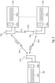
- Fig. 1 is a schematic representation of an example of a terrestrial wireless network 100 including, as is shown in Fig. 1(a) , a core network 102 and one or more radio access networks RANi, RAN 2 , ... RAN N .
- Fig. 1(b) is a schematic representation of an example of a radio access network RAN n that may include one or more base stations gNB 1 to gNB 5 , each serving a specific area surrounding the base station schematically represented by respective cells 106 1 to 106 5 .
- the base stations are provided to serve users within a cell.
- the one or more base stations may serve users in licensed and/or unlicensed bands.
- base station refers to a gNB in 5G networks, an eNB in UMTS/LTE/LTE-A/ LTE-A Pro, or just a BS in other mobile communication standards.
- a user may be a stationary device or a mobile device.
- the wireless communication system may also be accessed by mobile or stationary loT devices which connect to a base station or to a user.
- the mobile devices or the loT devices may include physical devices, ground based vehicles, such as robots or cars, aerial vehicles, such as manned or unmanned aerial vehicles (UAVs), the latter also referred to as drones, buildings and other items or devices having embedded therein electronics, software, sensors, actuators, or the like as well as network connectivity that enables these devices to collect and exchange data across an existing network infrastructure.
- Fig. 1(b) shows an exemplary view of five cells, however, the RAN n may include more or less such cells, and RAN n may also include only one base station.
- Fig. 1(b) shows two users UE 1 and UE 2 , also referred to as user equipment, UE, that are in cell 106 2 and that are served by base station gNB 2 .
- FIG. 1(b) shows two loT devices 110 1 and 110 2 in cell 106 4 , which may be stationary or mobile devices.
- the loT device 110 1 accesses the wireless communication system via the base station gNB 4 to receive and transmit data as schematically represented by arrow 112 1 .
- the loT device 110 2 accesses the wireless communication system via the user UEs as is schematically represented by arrow 112 2 .
- the respective base station gNB 1 to gNB 5 may be connected to the core network 102, e.g. via the S1 interface, via respective backhaul links 114 1 to 114 5 , which are schematically represented in Fig. 1(b) by the arrows pointing to "core".
- the core network 102 may be connected to one or more external networks. Further, some or all of the respective base station gNB 1 to gNB 5 may connected, e.g. via the S1 or X2 interface or the XN interface in NR, with each other via respective backhaul links 116 1 to 116 5 , which are schematically represented in Fig. 1(b) by the arrows pointing to "gNBs”.
- the physical resource grid may comprise a set of resource elements to which various physical channels and physical signals are mapped.
- the physical channels may include the physical downlink, uplink and sidelink shared channels (PDSCH, PUSCH, PSSCH) carrying user specific data, also referred to as downlink, uplink and sidelink payload data, the physical broadcast channel (PBCH) carrying for example a master information block (MIB) and a system information block (SIB), the physical downlink, uplink and sidelink control channels (PDCCH, PUCCH, PSCCH) carrying for example the downlink control information (DCI), the uplink control information (UCI) and the sidelink control information (SCI).
- PBCH physical broadcast channel
- MIB master information block
- SIB system information block
- PDCCH, PUCCH, PSCCH carrying for example the downlink control information (DCI), the uplink control information (UCI) and the sidelink control information (SCI).
- DCI downlink control information
- UCI uplink control information
- SCI sidelink control information
- the physical channels may further include the physical random access channel (PRACH or RACH) used by UEs for accessing the network once a UE synchronized and obtained the MIB and SIB.
- the physical signals may comprise reference signals or symbols (RS), synchronization signals and the like.
- the resource grid may comprise a frame or radio frame having a certain duration in the time domain and having a given bandwidth in the frequency domain.
- the frame may have a certain number of subframes of a predefined length, e.g. 1ms. Each subframe may include one or more slots of 12 or 14 OFDM symbols depending on the cyclic prefix (CP) length.
- a frame may also consist of a smaller number of OFDM symbols, e.g. when utilizing shortened transmission time intervals (sTTI) or a mini-slot/non-slot-based frame structure comprising just a few OFDM symbols.
- sTTI shortened transmission time intervals
- mini-slot/non-slot-based frame structure comprising just
- the wireless communication system may be any single-tone or multicarrier system using frequency-division multiplexing, like the orthogonal frequency-division multiplexing (OFDM) system, the orthogonal frequency-division multiple access (OFDMA) system, or any other IFFT-based signal with or without CP, e.g. DFT-s-OFDM.
- Other waveforms like non-orthogonal waveforms for multiple access, e.g. filter-bank multicarrier (FBMC), generalized frequency division multiplexing (GFDM) or universal filtered multi carrier (UFMC), may be used.
- FBMC filter-bank multicarrier
- GFDM generalized frequency division multiplexing
- UFMC universal filtered multi carrier
- the wireless communication system may operate, e.g., in accordance with the LTE-Advanced pro standard, or the 5G or NR, New Radio, standard, or the NU-U, New Radio Unlicensed, standard, or the 802.11ax, or the 802.11be.
- the wireless network or communication system depicted in Fig. 1 may by a heterogeneous network having distinct overlaid networks, e.g., a network of macro cells with each macro cell including a macro base station, like base station gNB 1 to gNB 5 , and a network of small cell base stations (not shown in Fig. 1 ), like femto or pico base stations.
- a network of macro cells with each macro cell including a macro base station, like base station gNB 1 to gNB 5 , and a network of small cell base stations (not shown in Fig. 1 ), like femto or pico base stations.
- non-terrestrial wireless communication networks including spaceborne transceivers, like satellites, and/or airborne transceivers, like unmanned aircraft systems.
- the non-terrestrial wireless communication network or system may operate in a similar way as the terrestrial system described above with reference to Fig. 1 , for example in accordance with the LTE-Advanced Pro standard or the 5G or NR, new radio, standard.
- a frequency band includes a start frequency, an end frequency and all intermediate frequencies between the start and end frequencies.
- the start, end and intermediate frequencies may define a certain bandwidth, e.g., 20MHz.
- a frequency band may also be referred to as a carrier, a bandwidth part, BWP, a subband, and the like.
- the communication may be referred to as a single-band operation, e.g., a UE transmits/receives radio signals to/from another network entity on frequencies being within the 20MHz band.
- the communication may be referred to as a multi-band operation or as a wideband operation or as a carrier aggregation operation.
- the frequency bands may have different bandwidths or the same bandwidth, like 20MHz.
- a UE may transmit/receive radio signals to/from another network entity on frequencies being within two or more of the 20MHz bands so that the frequency range for the radio communication may be a multiple of 20MHz.
- the two or more frequency bands may be continuous/adjacent frequency bands or some or all for the frequency bands may be separated in the frequency domain.
- the multi-band operation may include frequency bands in the licensed spectrum, or frequency bands in the unlicensed spectrum, or frequency bands both in the licensed spectrum and in the unlicensed spectrum.
- Carrier aggregation, CA is an example using two or more frequency bands in the licensed spectrum and/or in the unlicensed spectrum.
- 5G New Radio may support an operation in the unlicensed spectrum so that a multi-band operation may include frequency bands in the unlicensed spectrum bands.
- This may be as NR-based access to unlicensed spectrum, NR-U, and the frequency bands may be referred to as subbands.
- the unlicensed spectrum may include bands with a potential IEEE 802.11 coexistence, such as the 5GHz and the 6GHz bands.
- NR-U may support bandwidths that are an integer multiple of 20 MHz, for example due to regulatory requirements.
- the splitting into the subbands is performed so as to minimize interference with coexisting systems, like IEE 802.11 systems, which may operate in one or more of the same bands with the same nominal bandwidth channels, like 20 MHz channels.
- the unlicensed spectrum may include the 5GHz band, the 6GHz band, the 24GHz band or the 60GHz band.
- Examples of such unlicensed bands include the industrial, scientific and medical, ISM, radio bands reserved internationally for the use of radio frequency energy for industrial, scientific and medical purposes other than telecommunications.
- LBT Listen-before-talk
- the transmitter either the transmitting gNB or the transmitting UE, is only allowed to transmit on the subbands which are detected to be not busy, also referred to as subbands being free or non-occupied, as is determined by the LBT algorithm.
- the transmitter like the gNB or the UE, performs Listen-Before-Talk, LBT, separately on each subband.
- LBT Listen-Before-Talk
- the devices for example, the gNB in the downlink, DL, or the UE in the uplink, UL, are allowed to transmit on those subbands which are determined to be free or unoccupied, i.e., to transmit on the won subband(s). No transmission is allowed on the occupied, busy or non-won subbands.
- US 2018/227777 A1 describes configuring a transmission between a base station and a user equipment (UE) equipment.
- a plurality of control resource sets (Coresets) may be determined, and the plurality of Coresets may be grouped into one or more Corset groups.
- a Coreset group may include a first Coreset and a second Coreset. The first Coreset may provide a common search space, and the second Coreset may provide a UE specific search space.
- the one or more Coreset groups may be used to configure a transmission of data to the UE.
- the first Coreset and the second Coreset for a particular Coreset group may be configured to enable narrow band monitoring of the Coreset group by the UE.
- WO 2018/171807 A1 describes a resource configuration method and apparatus, a device and a computer-readable storage medium. The method comprises: configuring one or more groups of control resource sets, each group of control resource set containing one or more control resource sets, and when configuring multiple groups of control resource sets, each group of control resource sets in the multiple groups of control resource sets respectively corresponds to one group of time domain resources.
- ZTE ET AL "Consideration on Enhancement of TCI-State MAC CE for Muliti-TRP transmission", vol. RAN WG2, no. Reno, USA; 20190513 - 20190517, (20190513), 3GPP DRAFT; R2-1906125 refers to the use of one CORSET in a PDCCH that corresponds to one TRP, and to a redesign of a MAC CE which can be used for mapping one or two TCI states for a TCI code point in one DCI.
- ZTE "On multi-PDCCH design for multi-TRP", vol. RAN WG1, no. Reno, USA; 20190513 - 20190517, (20190513), 3GPP DRAFT; R1-1906242 refers to a multiple PDCCH design, including MAC-CE enhancement for TCI and PUCCH spatial relation and SRS.
- OPPO "Enhancements on multi-TRP and multi-panel transmission", vol. RAN WG1, no. Reno, USA; 20190513 - 20190517, (20190513), 3GPP DRAFT; R1-1906287 refers to a multiple PDCCH and single PDCCH based non-coherent joint transmission and enhancement for URLLC with multiple TRPs/panels.
- control information for users may be provided in a so-called control resource set, CORESET.
- the CORESET is a collection of time/frequency resources dedicated to the transmission of the control information, e.g. the PDCCH which carries the downlink control information, DCI, or scheduling information for respective UEs being within a certain cell or coverage area of a base station, gNB, or being served by the gNB.
- a CORESET may include a common search space, CSS, that is common across all the UEs in the cell and/or a UE specific search space, USS, that is specific to a particular UE in the cell.
- the gNB may assign different aggregation levels, ALs, per DCI per UE so as to maintain a certain reliability of decoding the PDCCH.
- ALs aggregation levels
- the UEs having a higher AL may require a larger allocation of the time/frequency resources within the CORESET.
- a UE does not have prior knowledge of the AL and, therefore, considers all possible aggregation levels which are indicated in the search space configurations of the CORESET.
- the aggregation level may be 1, 2, 4, 8 and 16, meaning that a certain PDCCH has allocated 1, 2, 4, 8 or 16 control channel elements, CCEs.
- Considering all possible aggregation levels means that the UE performs blind decoding for each AL. More specifically, blind decoding the CORESET initially involves extracting the appropriate time/frequency resources associated with the CORESET, as specified, for example, by a certain radio resource control, RRC, configuration. Then, for each AL, the UE performs a certain number of decodings on the extracted resources to check the result of the CRC.
- RRC radio resource control
- the UE may consider the DCI meant for itself and it may continue to decode the subsequent PDCCH channels.
- the UE needs to perform the decoding at least in such subbands that carry the control information or that include CORESETs.
- the frequency band may include a plurality of CORESETs provided at different time/frequency resources within the frequency band.
- one or more or all of the frequency bands may include one or more CORESETs that are provided at certain time/frequency resources within the frequency bands.
- a receiver like a UE, may be configured with respective CORESET configurations indicating the CORESETs including search spaces carrying control information for this UE.
- the base station or gNB may decide not to transmit a CORESET in one or more of the frequency bands, e.g., because no control information is available for a transmission or a more stringent transmission has to be transmitted. For example, a high priority packet for a URLLC device may arrive and the gNB may decide to prioritize the high priority packet over the CORESET transmission. This leads to an increased blind decoding effort of the UE.
- the UE may first scan for the presence of a CORESET, e.g. using a DMRS correlation, or monitor an indication from the gNB, e.g.
- an increase of power consumption and, in turn, a reduction in energy efficiency may occur in systems operating in one or more frequency bands of the licensed spectrum. More specifically, in systems operating in one or more frequency bands of the licensed spectrum a UE has to do the blind decoding on all CORESETs in one or more of the frequency bands used.
- LBT subbands may be configured with a respective CORESET which needs to be decoded by a UE which, inherently, reduces the energy/power efficiency, like the battery lifetime, at the UE side.
- the UE scheduling or control information may span across all or some of the subbands so that the UE may perform a blind decoding on each of the subbands independently.
- the UE may first scan all the subbands using a reference signal decorrelation, like a DMRS decorrelation, so as to check the result of the LBT procedure and then perform blind decoding of the PDCCH across those subbands where the LBT is successful.
- a reference signal decorrelation like a DMRS decorrelation
- Information regarding the result of a LBT procedure i.e., information which subbands are available for reception, may be transmitted in the group-common, GC, PDCCH as part of the CCEs of a CORESET. Since the LBT procedure may be applied several times during a gNB COT, the UE performs the blind decoding of the CG-PDCCH at the corresponding number of times within the COT also resulting in an increase of power consumption and, in turn, a reduction in energy efficiency.
- Embodiments of the present invention provide improvements and enhancements addressing the above issues and reducing or avoiding an increase in power consumption and a reduction in energy efficiency when communicating over one or more frequency band carrying control information to be obtained by the UE or different service types which may preempt a CORESET transmission are served simultaneously by the same serving cell or the gNB is optimized to reduce the CORESET transmissions if possible to increase the available bandwidth for data transmissions.
- Embodiments of the present invention may be implemented in a wireless communication system as depicted in Fig. 1 including base stations and users, like mobile terminals or loT devices.
- Fig. 2 is a schematic representation of a wireless communication system including a transmitter 300, like a base station, and one or more receivers 302 1 to 302 n , like user devices, UEs.
- the transmitter 300 and the receivers 302 may communicate via one or more wireless communication links or channels 304a, 304b, 304c, like a radio link.
- the transmitter 300 may include one or more antennas ANT T or an antenna array having a plurality of antenna elements, a signal processor 300a and a transceiver 300b, coupled with each other.
- the receivers 302 include one or more antennas ANT R or an antenna array having a plurality of antennas, a signal processor 302a 1 , 302a n , and a transceiver 302b 1 , 302b n coupled with each other.
- the base station 300 and the UEs 302 may communicate via respective first wireless communication links 304a and 304b, like a radio link using the Uu interface, while the UEs 302 may communicate with each other via a second wireless communication link 304c, like a radio link using the PC5 interface.
- the UEs When the UEs are not served by the base station, are not be connected to a base station, for example, they are not in an RRC connected state, or, more generally, when no SL resource allocation configuration or assistance is provided by a base station, the UEs may communicate with each other over the sidelink.
- the system, the one or more UEs 302 and the base stations 300 may operate in accordance with the inventive teachings described herein.
- the present invention provides (see for example claim 1) a user device, UE, for a wireless communication system, wherein the UE is to be served by a base station and is to use one or more frequency bands for a communication with one or more entities, e.g., other UE(s) or other gNB(s) in the wireless communication system, wherein one or more or all of the frequency bands include one or more CORESETs, each CORESET including one or more search spaces carrying control information, e.g., DCI(s), for the UE,
- the UE is to use one frequency band for the communication, and a CORESET group/search space group includes some or all CORESETs/search spaces in the one frequency band that are provided within a certain time window, or the UE is to use a plurality of frequency bands for the communication, and a CORESET group/search space group includes some or all CORESETs/search spaces in one or more or all of the plurality of frequency bands that are provided within a certain time window.
- the certain time window comprises one or more slots or a plurality of consecutive symbols.
- the UE is to group the search spaces further based on one or more of the following parameters in a search space information element (searchspace):
- searchspace search space information element
- the UE is to be configured with a CORESET group information element, the CORESET group information element indicating CORESET configurations to be considered for the grouping.
- the UE is to be configured, e.g., using RRC signaling, with one or more CORESET information elements (ControlResourceSet), wherein a CORESET information element includes the group ID (groupIndex) so as to indicate which CORESET configurations to consider for the grouping.
- ControlResourceSet one or more CORESET information elements
- groupIndex group ID
- the UE is to be configured with a search space group information element, the search space group information element indicating search spaces and associated CORESETs being part of the same search space group.
- the UE is to be configured, e.g., using RRC signaling, with one or more CORESET information elements (controiResourceSet) and one or more search space information elements (searchSpace), wherein a search space information element includes a search space group indication element (searchSpaceGroup) including the group ID (groupIndex).
- a search space information element includes a search space group indication element (searchSpaceGroup) including the group ID (groupIndex).
- the UE is to be configured with a parameter activating or deactivating the grouping.
- the UE is to coordinate decoding the control information for the UE from the search spaces using the grouping, wherein the decoding may include blind decoding.
- the UE is to concatenate or combine the CORESETs or the search spaces of a group, whereby a virtual CORESET or a virtual search space is defined.
- the UE is to not expect more than one or more particular control parameters, e.g., one DL assignment per serving cell, or one UL grant per serving cell, within the virtual search space or the virtual CORESET.
- one or more particular control parameters e.g., one DL assignment per serving cell, or one UL grant per serving cell
- the UE is to receive a default CORESET configuration for a group, and to configure the remaining CORESETs of the group according to the default CORESET configuration.
- the UE is to apply at least a part of a search space configuration of the default CORESET to the other CORESETs of the same group.
- the default CORESET configuration is indicated:
- the UE is to replicate a default CORESET configuration for further frequency domain monitoring locations in one or more subbands that are different from the subband associated with the default CORESET configuration.
- the UE in case the UE successfully finds control information, e.g., DCI(s), in a current CORESET having a certain aggregation level, AL, the UE is not to expect control information for itself, e.g., DCI(s), in a CORESET with another AL, or in case the UE successfully finds control information, e.g., DCI(s), in a current search space having a certain aggregation level, AL, the UE is not to expect control information for itself, e.g., DCI(s), in a search space with another AL.
- control information e.g., DCI(s)
- the UE in case the UE successfully finds control information, e.g., DCI(s), in a current CORESET having a certain aggregation level, AL, the UE is not to expect control information for itself, e.g., DCI(s), in a search space with another AL.
- the UE is to continue looking only for the certain AL in the current and in the other CORESETs/search spaces of the same CORESET group/search space group at least for the successfully decoded DCI format.
- control information e.g., DCI(s)
- the UE in case the UE successfully finds control information, e.g., DCI(s), in a current CORESET, the UE is not to expect control information for itself, e.g., DCI(s), in another CORESETs.
- the UE responsive to successfully detecting a PDCCH in a certain subband, e.g., in one of the frequency domain monitoring locations, i.e. a CORESET of a CORESET group, for a time window, e.g. a COT duration or an uninterrupted DL burst, the UE is to continue to blind decode only within the frequency domain monitoring location, i.e. a CORSET of a CORESET group, at which the PDCCH is found for the search space associated with the found PDCCH or a pre-configured subset or all search spaces which are associated with the CORESET group.
- the CORESETs or search spaces of a certain group are prioritized or ranked, and wherein the UE is to blind decode the CORESETs or search spaces of the certain group according to the prioritization or ranking thereof.
- the UE is to receive from the BS an indication of the prioritization or ranking of the CORESETs or the search spaces of the certain group, e.g., upon receiving the CORESET or search space configurations.
- the UE responsive to decoding control information, e.g., DCI(s), from a CORESET or from a search space of a group, the UE is to apply a timing before which the UE is not to accept a DL assignment or an UL grant, the timing selected dependent on the priority or rank of the CORESET or search space, wherein the timing may decrease with an increase in priority or rank.
- decoding control information e.g., DCI(s)
- the UE is to apply a timing before which the UE is not to accept a DL assignment or an UL grant, the timing selected dependent on the priority or rank of the CORESET or search space, wherein the timing may decrease with an increase in priority or rank.
- control information of some or all of the CORSETs indicate in which of the CORSETs out of the CORESET group control information for the UE is present.
- the present invention provides (see for example claim 26) a user device, UE, for a wireless communication system, wherein the UE is to be served by a base station and is to use one or more frequency bands for a communication with one or more entities, e.g., other UE(s) or other gNB(s), in the wireless communication system, wherein one or more or all of the frequency bands include one or more CORESETs carrying control information, e.g., DCI(s), for the UE, and wherein the control information of some or all of the CORSETs indicate in which of the CORSETs control information for the UE is present.
- a user device UE
- the UE is to be served by a base station and is to use one or more frequency bands for a communication with one or more entities, e.g., other UE(s) or other gNB(s), in the wireless communication system, wherein one or more or all of the frequency bands include one or more CORESETs carrying control information, e.g.,
- a CORSET includes a DCI pointing to or indicating the CORSETs including control information for the UE.
- the present invention provides (see for example claim 28) a user device, UE, for a wireless communication system, wherein the UE is to be served by a base station and is to use a plurality of frequency bands for a communication with one or more entities, e.g., other UE(s) or other gNB(s), in the wireless communication system, wherein some, e.g., two or more, or all of the plurality of frequency bands include one or more CORESETs carrying control information, e.g., DCI(s), for the UE, wherein the UE is to decode the control information, e.g., DCI(s), from one or more of the CORSETs, and wherein in one or more neighboring frequency bands one or more of the CORESETs are located within a pre-defined continuous frequency range extending in both neighboring frequency bands.
- a user device UE
- the UE for a wireless communication system, wherein the UE is to be served by a base station and is to use a pluralit
- the UE is configured to monitor only the continuous frequency range at least for the duration of the CORESETs.
- the UE comprises a timer, the timer to start at the end of the CORESETs, and the UE is to receive UL grants or DL assignments located within the whole of the one or more neighboring frequency bands after the timer expired.
- one or more or all of the frequency bands are unlicensed subbands, and wherein
- the one or more CORESETs carrying control information for the UE are transmitted once or several times during the certain transmission time (COT).
- the UE is to stop or deactivate blind decoding for search spaces or CORESETs in unlicensed subbands in which the LBT failed.
- the present invention provides (see for example claim 34) a user device, UE, for a wireless communication system, wherein the UE is to be served by a base station and is to use one or more frequency bands for a communication with one or more entities, e.g., other UE(s) or other gNB(s), in the wireless communication system, wherein one or more or all of the frequency bands include one or more CORESETs carrying control information, e.g. DCI(s), for the UE, and wherein one or more backup CORESETs are provided in one or more of the frequency bands.
- the UE is configured or preconfigured with locations of the one or more backup CORESETs in the one or more frequency bands.
- the UE is to employ a backup CORESET
- one or more or all of the plurality of frequency bands are unlicensed subbands on which a communication is allowed for a certain transmission time (COT) responsive to a successful Listen-Before-Talk, LBT, and following a failed gNB LBT for a certain unlicensed subband, the UE is to employ within the certain transmission time (COT) one or more backup CORESETs in one or more of the unlicensed subbands where the LBT was successful, e.g., in one or more unlicensed subbands other than a default unlicensed subband.
- COT transmission time
- the UE is to perform blind decoding for control information, e.g., DCI(s), according to a CORESET or search space prioritization and/or based on an indication which CORESETs are indicated to be transmitted or to include information for the UE.
- control information e.g., DCI(s)
- the UE is to equally or unequally distribute the number of the blind decoding attempts across the CORESETs and/or search spaces.
- the UE is to skip CORESETs and/or search spaces that are indicated to be not transmitted or not meant for the UE.
- the UE is to increase a number of blind decodes per search space within a search space group based on a formula in response to detecting that other search spaces of the same group are not transmitted or not relevant for the UE.
- the total number of blind decodes per search space group stays the same.
- the UE is to monitor only a subset of the CORESETs carrying control information, e.g., DCI(s), for the UE, e.g., responsive to an RRC configuration or reconfiguration message.
- control information e.g., DCI(s)
- the subset of CORESETs to monitor is chosen based on detecting actually transmitted CORESETs out of a CORESET group.
- the CORESETs to be monitored are selected so as to achieve a required distribution of the UEs across two or more of the frequency bands, e.g., to achieve load balancing.
- the UE is to determine the CORESETs to be monitored as a subset of a CORESET group based on a formula indicated by the gNB which incorporates the number of actually transmitted CORESETs.
- the UE is configured with a UE ID and, to determine an index of a CORESET to be monitored out of the actually transmitted CORESETs, the UE is to calculate (UE ID) % (Number of actually transmitted CORESETs), wherein % indicates the modulo operation.
- the present invention provides (see for example claim 48) a base station, BS, for a wireless communication system, wherein the BS is to serve one or more UEs and is to use one or more frequency bands for a communication with the one or more UEs in the wireless communication system, wherein one or more or all of the frequency bands include one or more CORESETs carrying control information for the one or more UEs, and wherein the BS is to configure, e.g., using RRC signaling, the one or more UEs with one or more group IDs, each group ID pointing to or indicating a group of one or more other CORESETs or one or more search spaces, wherein a CORESET group includes some or all CORESETs within a certain time window, and wherein a search space group includes some or all search spaces within the certain time window.
- the BS is to include into some or all of the CORSETs an indication in which of the CORSETs out of the CORESET group control information for a certain UE is present.
- the present invention provides (see for example claim 50) a base station, BS, for a wireless communication system, wherein the BS is to serve one or more UEs and is to use one or more frequency bands for a communication with one or more UEs in the wireless communication system, wherein one or more or all of the frequency bands include one or more CORESETs carrying control information, e.g., DCI(s), for the UE, and wherein the control information of some or all of the CORSETs indicate in which of the CORSETs in one or more other of the frequency bands control information for a receiving UE is present.
- BS base station
- the BS is to serve one or more UEs and is to use one or more frequency bands for a communication with one or more UEs in the wireless communication system
- one or more or all of the frequency bands include one or more CORESETs carrying control information, e.g., DCI(s), for the UE, and wherein the control information of some or all of the CORSETs indicate in which of
- the present invention provides (see for example claim 51) a base station, BS, for a wireless communication system, wherein the BS is to serve one or more UEs and is to use a plurality of frequency bands for a communication with the one or more UEs, wherein some, e.g., two or more, or all of the plurality of frequency bands include one or more CORESETs carrying control information, e.g., DCI(s), for the one or more UEs, and wherein the BS is to transmit CORESETs of one or more neighboring frequency bands within a pre-defined continuous frequency range extending both in both neighboring frequency bands.
- BS for a wireless communication system
- the BS is to serve one or more UEs and is to use a plurality of frequency bands for a communication with the one or more UEs, wherein some, e.g., two or more, or all of the plurality of frequency bands include one or more CORESETs carrying control information, e.g., DCI(s), for
- the present invention provides (see for example claim 52) a base station, BS, for a wireless communication system, wherein the BS is to serve one or more UEs and is to use one or more frequency bands for a communication with the one or more UEs in the wireless communication system, wherein one or more or all of the frequency bands include one or more CORESETs carrying control information, e.g., DCI(s), for the UE, and wherein the BS is to configure the one or more UEs with one or more backup CORESETs in the one or more frequency bands.
- BS for a wireless communication system
- the BS is to serve one or more UEs and is to use one or more frequency bands for a communication with the one or more UEs in the wireless communication system, wherein one or more or all of the frequency bands include one or more CORESETs carrying control information, e.g., DCI(s), for the UE, and wherein the BS is to configure the one or more UEs with one or more backup CORESETs
- the present invention provides (see for example claim 53)a base station, BS, for a wireless communication system, wherein the BS is to serve one or more UEs and is to use a plurality of frequency bands for a communication with the one or more UEs in the wireless communication system, wherein one or more or all of the plurality of frequency bands include one or more CORESETs carrying control information, e.g., DCI(s), for the UE, and wherein some or all of the plurality of frequency bands are unlicensed frequency bands on which a communication is allowed for a certain transmission time (COT) responsive to a successful Listen-Before-Talk, LBT, and wherein, responsive to an unsuccessful or failed LBT on one or more of the unlicensed frequency bands, the BS is to distribute the control information for the one or more UEs among the one or more frequency bands available for the communication, e.g., among one or more frequency bands which passed the LBT.
- COT transmission time
- the one or more UEs served by the BS are configured with a UE ID and the BS is to indicate out of the actually transmitted CORESETs an index of a CORESET to be monitored by the one or more served UEs, the BS is to calculate (UE ID) % (Number of actually transmitted CORESETs), wherein % indicates the modulo operation.
- the BS is to redistribute the control information, e.g., DCI(s), according to a CORESET or search space prioritization and/or based on an indication which CORESETs are to be transmitted or to include information for a specific UE.
- control information e.g., DCI(s)
- the present invention provides (see for example claim 56) a wireless communication system, comprising one or more UEs in accordance with the present invention, and one or more BSs in accordance with the present invention.
- the UE comprises one or more of a mobile terminal, or stationary terminal, or cellular IoT-UE, or vehicular UE, or vehicular group leader (GL) UE, an IoT or narrowband loT, NB-loT, device, or a WiFi non Access Point STAtion, non-AP STA, e.g.
- 802.11 ax or 802.11 be, or a ground based vehicle, or an aerial vehicle, or a drone, or a moving base station, or road side unit, or a building, or any other item or device provided with network connectivity enabling the item/device to communicate using the wireless communication network, e.g., a sensor or actuator, and/or the BS comprises one or more of a macro cell base station, or a small cell base station, or a central unit of a base station, or a distributed unit of a base station, or a road side unit, or a UE, or a group leader (GL), or a relay, or a remote radio head, or an AMF, or an SMF, or a core network entity, or mobile edge computing entity, or a network slice as in the NR or 5G core context, or a WiFi AP STA, e.g. 802.11ax or 802.11be, or any transmission/reception point, TRP, enabling an item or a device to communicate using the wireless communication
- the present invention provides (see for example claim 58) a method for operating a wireless communication system, wherein a UE is served by a base station and uses one or more frequency bands for a communication with one or more entities, e.g., other UE(s) or other gNB(s) in the wireless communication system, wherein one or more or all of the frequency bands include one or more CORESETs, each CORESET including one or more search spaces carrying control information, e.g., DCI(s), for the UE, and wherein method comprises grouping some or all of the CORESETs into respective CORESET groups, or some or all of the search spaces into respective search space groups,
- the present invention provides (see for example claim 59) a method for operating a wireless communication system, wherein a UE is served by a base station and uses one or more frequency bands for a communication with one or more entities, e.g., other UE(s) or other gNB(s), in the wireless communication system, wherein the one or more or all of the frequency bands include one or more CORESETs carrying control information, e.g., DCI(s), for the UE, and wherein the method comprises indicating in the control information of some or all of the CORSETs in which of the CORSETs control information for the UE is present.
- a UE is served by a base station and uses one or more frequency bands for a communication with one or more entities, e.g., other UE(s) or other gNB(s), in the wireless communication system, wherein the one or more or all of the frequency bands include one or more CORESETs carrying control information, e.g., DCI(s), for the UE,
- the present invention provides (see for example claim 60) a method for operating a wireless communication system, wherein the UE is served by a base station and uses a plurality of frequency bands for a communication with one or more entities, e.g., other UE(s) or other gNB(s), in the wireless communication system, wherein some, e.g., two or more, or all of the plurality of frequency bands include one or more CORESETs carrying control information, e.g., DCI(s), for the UE, wherein the UE decodes the control information, e.g., DCI(s), from one or more of the CORSETs, and wherein the method comprises locating in one or more neighboring frequency bands one or more of the CORESETs within a pre-defined continuous frequency range extending in both neighboring frequency bands.
- the method comprises locating in one or more neighboring frequency bands one or more of the CORESETs within a pre-defined continuous frequency range extending in both neighboring frequency bands.
- the present invention provides (see for example claim 61) a method for operating a wireless communication system, wherein the UE is served by a base station and uses one or more frequency bands for a communication with one or more entities, e.g., other UE(s) or other gNB(s), in the wireless communication system, wherein one or more or all of the frequency bands include one or more CORESETs carrying control information, e.g. DCI(s), for the UE, and wherein the method comprises providing one or more backup CORESETs in one or more of the frequency bands.
- entities e.g., other UE(s) or other gNB(s
- the method comprises providing one or more backup CORESETs in one or more of the frequency bands.
- the present invention provides (see for example claim 62) a method for operating a wireless communication system, wherein a BS serves one or more UEs and uses a plurality of frequency bands for a communication with the one or more UEs in the wireless communication system, wherein one or more or all of the plurality of frequency bands include one or more CORESETs carrying control information, e.g., DCI(s), for the UE, and wherein some or all of the plurality of frequency bands are unlicensed frequency bands on which a communication is allowed for a certain transmission time (COT) responsive to a successful Listen-Before-Talk, LBT, and wherein the method comprises, responsive to an unsuccessful or failed LBT on one or more of the unlicensed frequency bands, distributing, by the BS, the control information for the one or more UEs among the one or more frequency bands available for the communication, e.g., among one or more frequency bands which passed the LBT.
- COT transmission time
- the present invention provides a computer program product comprising instructions which, when the program is executed by a computer, causes the computer to carry out one or more methods in accordance with the present invention.
- the present invention provides embodiments for improving or enhancing the energy efficiency of a UE communicating in a wireless communication system using a one or more frequency bands wherein one or more or all of the frequency bands include control information for the UE, and wherein the UE is to scan for the control information in a plurality of control regions, e.g. CORESETs, in the one or more frequency bands.
- a plurality of control regions e.g. CORESETs
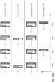
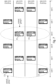
- Fig. 3(a) schematically illustrates a single-band transmission between a base station and a UE, or, in accordance with other embodiments, between two UEs, including respective control information for the receiving UE.
- the communication over the frequency band SB comprises a plurality of time windows or slots.
- Fig. 3(a) illustrates four slots of the communication, namely slot 0, slot 1, slot 2 and slot 3.
- each of the slots includes control information, for example DCls, for one or more UEs that are served, for example, by a base station.
- the control information is provided in respective control resource sets, CORESETs.
- CORESETs In the embodiment of Fig. 3(a) , in slot 0, three CORESETs C1 to C12 are transmitted.
- Each of the CORESETs includes the control information for one or more UEs, for example the UEs being within a cell of a base station, i.e., for UEs being served by a base station.
- the different UEs may be one or more UEs with which a transmitting UE performs a communication over a sidelink.
- the invention is not limited to the specific configuration of control information transmission as indicated in Fig. 3(a) , rather a different number of CORESETs may be transmitted in the respective slots.
- Fig. 3(b) schematically illustrates a multi-band transmission between a base station and a UE, or, in accordance with other embodiments, between two UEs, including respective control information for the receiving UE.
- a multi-band transmission is assumed, in the licensed spectrum and/or in the unlicensed spectrum, using four immediately consecutive frequency bands, SB0 to SB3.
- the frequency bands SB0 to SB3 may have the same bandwidths, however, the inventive the inventive approach is not limited to such embodiments, rather, some or more of the frequency bands may have different bandwidths.
- each of the slots includes control information, for example DCls, for one or more UEs that are served, for example, by a base station.
- the control information is provided in respective control resource sets, CORESETs.
- each of the CORESETs includes the control information for one or more UEs, for example the UEs being within a cell of a base station, i.e., for UEs being served by a base station.
- the different UEs may be one or more UEs with which a transmitting UE performs a communication over a sidelink.
- the invention is not limited to the specific configuration of control information transmission as indicated in Fig. 3(b) , rather a different number of CORESETs may be transmitted in the respective slots.
- the frequency bands are also referred to as subbands.
- Each of the CORESETs includes one or more search spaces, SS, in which the actual control information is transmitted.
- some of the CORESETs have two search spaces, SS0, SS1 (see CORESETs C1, C3 to C5, C7, C9 to C11), while others have only a single search space SS0 or SS1 (see CORESETs C2, C3, C6, C8 and C12).
- more than two search spaces may be provided within a CORESET.
- a UE receiving a communication from a transmitter like a base station or another UE, including the plurality of bands as indicated in Fig. 3 performs blind decoding in the respective CORESETs so as to find search spaces carrying control information for this specific UE.
- the search spaces are the possible locations for the control information for the UE, and each of the possible locations is also referred to as a PDCCH candidate.
- blind decoding over all of the CORESETs may not be efficient in terms of energy efficiency and the like, so that in accordance with embodiments of the present invention the UE may perform a CORESET or search space grouping, for example on the basis of configurations being consistent for different CORESETs in the one frequency band or across different frequency bands.
- the grouping may be referred to as an explicit grouping, which includes a group ID that is received by the UE, for example from the transmitter, like the base station or the transmitting UE in a sidelink communication, and which indicates one or more CORESETs or search spaces that form a CORESET group or a search space group.
- the grouping may be performed at the UE without further information or signaling from the transmitter, which is also referred to as an implicit grouping.
- the UE determines CORESETs or search groups having a consistent configuration in the one or more frequency bands and groups them into a group.
- CORESETs or search spaces that share a common time window for example, CORESETs or search spaces that share the same slot or a certain duration within a slot or that share a number of consecutive symbols within a slot or the like are considered to form a group.
- the number of consecutive symbols may include a plurality of immediately consecutive symbols or consecutive symbols separated, e.g., by one or more reference symbols.
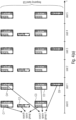
- Fig. 4 illustrates an embodiment in accordance with which search space grouping is applied.
- Fig. 4(a) illustrates a single-band communication similar as in Fig. 3(a) .
- search spaces of respective CORESETs which are within a predefined time window which, in the example of Fig. 4(a) span a number of predefined consecutive symbols, are grouped together.
- Fig. 4(b) illustrates a multi-band communication similar as in Fig. 3(b) .
- search spaces of respective CORESETs which are within a predefined time window, which, in the example of Fig. 4 span a number of predefined consecutive symbols are grouped together.
- Fig. 4(a) illustrates a single-band communication similar as in Fig. 3(a) .
- search spaces of respective CORESETs which are within a predefined time window which, in the example of Fig. 4 span a number of predefined consecutive symbols
- the respective search spaces SS0 of the CORESETs C1, C2 and C3 are within a common or overlapping time window and are grouped together into search space group I.
- the search spaces SS1 of the respective CORESETs C4, C5 and C6 which are provided within an at least overlapping time window, in the example again using the same consecutive symbols within slot 1, are grouped together into the search space group II.
- the grouping may be signaled to the UE explicitly, for example, by the transmitter, like the gNB or another UE transmitting information towards the UE. More specifically, the search groups may have assigned a certain group index or group identification, and the UE may be configured by the transmitter, for example using an RRC signaling as indicated below, with the respective group IDs indicating those search spaces in the respective CORESETs which belong to a common group. Below, an example of an RRC message with the CORESET group configuration in the SearchSpace config is shown
- the above RRC message may be an existing Release 15 search space configuration (TS 38.311) further including a CORESET group configuration.
- the CORESET group configuration includes a group index and optionally the corresponding CORESET ID(s), which are part of this group.
- the following RRC configuration element may be employed, which, other than the previously described one, only includes the group ID.
- the above RRC message may be an existing Release 15 search space configuration (TS 38.311) further including a group index.
- the search space group includes search spaces being provided within a common time window.
- the search spaces may be grouped further on the basis of the monitoring periodicity, the symbols to be monitored within a slot and other values described in the respective fields of the search space IE.
- the grouping may be done implicitly by the UE using information from the configurations of the search spaces. For example, the UE may recognize from the received configuration information those search spaces which have an overlapping or the same time window. For example, search spaces that span, at least partially, the same number of OFDM symbols in a certain slot are considered by the UE to belong to a common group in a certain slot as indicated in Fig. 4 .
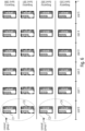
- Fig. 5 illustrates schematically the inventive approach of a CORESET grouping.
- Fig. 5(a) illustrates a communication including a single frequency band SB using respective slots 0 to 5 for a transmission from a transmitter, like gNB or a UE, to a receiving UE.
- a transmitter like gNB or a UE
- FIG. 5(b) illustrates a communication including a plurality of frequency bands SB0 to SB3, e.g., subbands in case of NR-U, using respective slots 0 to 5 for a transmission from a transmitter, like gNB or a UE, to a receiving UE.
- the CORESETs carrying the respective control information in the associated search spaces are indicated.
- CORESETs being within a certain time window, for example, being located in the same slot or being located within a slot at overlapping times, for example using overlapping OFDM symbols, are grouped into a CORESET group.
- Fig. 5 illustrates schematically CORESETs C1 to C4 in slot 0 which form the CORESET group I.
- one or more of the CORESETs in the other slots may define respective CORESET groups.
- the CORESET grouping may be done explicitly or implicitly.
- the UE may receive from the transmitter a configuration indicating, in addition to the respective fields needed for defining the CORESETs, also a group index indicating those CORESETs forming a certain CORESET group.
- the explicit CORESET group signaling may include a CORESET group index information element in an RRC message, for example in the part of an existing Release-15 CORESET configuration as depicted below.
- the receiving UE determines from the received configuration information those CORESETs that share the certain time window and associates some or all of the CORESETs determined with a common group.
- inventive approach is not limited to grouping all CORESETs or all search space within a certain slot and fulfilling the requirement of being within a certain predetermined time window into a common group. Rather, CORESETs or search spaces, which fulfill the requirement for grouping may be further grouped into further groups dependent on additional parameters. For example, search spaces being within a certain time window may further be grouped dependent on their monitoring periodicity, symbols to be monitored within a slot and the like. Also, CORESETs may be grouped dependent on further parameters like CORESET instances lying in the same time window, like a slot, or the monitoring periodicities and offsets of their search space configurations or the subband the CORESETs are assigned to. Fig.
- FIG. 6 illustrates, with respect to the CORESET grouping in an NR-U system, an embodiment in accordance with which CORESETs fulfilling the requirement of being within a certain time window are further separated into different groups dependent on one or more of the above mentioned further parameters.
- the CORESETs C1 to C4 that are provided in slot 0 and which are considered to be within a certain time window are further separated into CORESET groups I and II including CORESETs C1, C2 and C3, C4, respectively.
- the embodiment of Fig. 6 is equally applicable for a single-band operation or for a multi-band operation in the licensed spectrum.
- the present invention is not limited to the grouping of CORESETs having a structure as illustrated in Fig. 4 , namely to CORESETs having the same search space configurations.
- the CORESET grouping may group CORESETs with different search space configurations, as is illustrated in Fig. 7 showing, in a similar way as in Fig. 3(b) , multi-band communication between a transmitter and a receiving UE in which the CORESETs C1 and C2 in slot 0 having a first search space configuration are grouped into CORESET group I, while CORESETs C3 and C4 having a different search space configuration in slot 3 for CORESET group II.
- the embodiment of Fig. 7 is equally applicable for a single-band operation or for a multi-band operation in the licensed spectrum.
- Fig. 8 illustrates an embodiment combining CORESET grouping and search space grouping.
- the CORESETs C1 to C4 in slot 0 form a CORESET group I
- the search spaces SS0 of the CORESETs C1 to C4 in the CORESET group I form a first search space group I
- the search spaces SS1 in CORESETs C5 to C8 in slot 1 form a second search space group II.
- the embodiment of Fig. 8 is equally applicable for a single-band operation or for a multi-band operation in the licensed spectrum.
- the grouping is based on a location of the respective CORESETs or search spaces within a certain time window. Two or more of the CORESETs or search spaces may be grouped into common groups in case they fall into a common time window.
- the grouping may be based on the just mentioned similar configurations in the search space or CORESET RRC configurations, respectively. Further, the grouping may be useful not for all communications but only for certain types of communications that need to fulfill certain requirements.
- the CORESET or search space grouping allows to reduce the blind decoding effort of the UE significantly without sacrificing latency and reliability.
- a group on/off approach is provided so as to allow the grouping to be enabled or disabled dependent on, e.g., certain requirements to be fulfilled for a communication.
- the configuration provided to the UE may include an indication or parameter that the grouping is to be activated or deactivated, for example by providing a grouping field being set to true or false.
- the grouping is indicated to be non-activated for one or more CORESETs, such CORESETs may not be part of a group, i.e., the grouping process, either the explicit one or the implicit one, does not consider CORESETs or search spaces for which the grouping is disabled.
- Fig. 9 illustrates schematically this embodiment with reference to the CORESET grouping.
- some configurations include an indication as to the grouping, i.e., whether it is active or non-active, and such configurations may be employed for forming respective groups, in case the grouping indication is activated.
- the CORESET configuration for CORESETs C1 and C2 in slot 0 or the respective search space configurations associated with CORESETs C1 and C2 are not provided with a grouping indication so that the UE does not consider these CORESETs or the respective associated search spaces thereof as candidates for forming a group.
- the CORESETs C3 to C5 in slot 1 are assumed to have a CORESET configuration or a search space configuration including the grouping indication so that, in case the grouping indication is set to on or true, the UE, either implicitly or explicitly, may group the CORESETs C3 to C5 into a group or the respective search spaces SS0, SS1 into the different search space groups.
- the CORESETs C7, C8, C12, and C13 in slots 2 and 4, respectively, are assumed to a have a similar configuration with regard to the grouping as the CORESETs C1 and C2 in slot 0.
- the CORESETs C9 to C11 and C14 to C16 in slots 3 and 5, respectively, are assumed to have a similar configuration with regard to the grouping as the CORESETs C3 to C5 in slot 1, i.e., the respective CORESETs C9 to C11 and C14 to C16 may be grouped into respective CORESETs if the grouping is activated, or the corresponding search spaces SS0, SS1 may be grouped into respective search space groups.
- the embodiment of Fig. 9 is equally applicable for a single-band operation or for a multi-band operation in the licensed and/or unlicensed spectrum.
- the grouping of for the respective CORESETs may allow the UE to coordinate the decoding of the control information for the UE from the configured CORESETs.
- the UE may create a virtual search space by combining or concatenating search spaces of the CORESETs of a CORESET group.
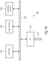
- Fig. 10 schematically illustrates an embodiment in which the UE creates a virtual search space, also referred to as a group search space.
- Fig. 10 illustrates the signaling of control information locations for a specific UE assuming an NR-U transmission using three subbands SB0 to SB3.
- the subbands include the CORESETs C1 to C4 which form a CORESET group.
- the CORESETs include the respective search spaces SS0 to SS4 that are illustrated by the differently shaded rectangular portions of the CORESETs C1 to C4.
- a group search space is defined including the search space SS0' formed by concatenating search spaces SS0 from CORESETs C1 to C4, the search space SS1' formed by concatenating search spaces SS1 from CORESETs C1 to C4, the search space SS2' formed by concatenating search spaces SS2 from CORESETs C1 to C4, the search space SS3' formed by concatenating search spaces SS3 from CORESETs C1 to C4, and the search space SS4' formed by concatenating search spaces SS4 from CORESETs C1 to C4. Furthermore, the CORESETs of a CORESET group lying in the same time window like
- providing the group search space may be advantageous because the UE may not expect more than one or more particular control parameters (e.g., one DL assignment per serving cell, one UL grant per serving cell) within a virtual search space or a virtual CORESET, also referred to as a group search space or as a group CORESET.
- the UE may stop blind decoding after successfully decoding one or more DCIs.
- the UE may expect to receive only a certain number of control parameters, like a single DL assignment, per serving cell, so that once it finds the DL assignment for the specific serving cell it may stop the blind decoding for that specific DCI format, i.e., all remaining search spaces of the group search space or the group CORESET are not searched any further.
- the UE once the UE successfully decoded one PDCCH in a CORESET of one subband, in case a plurality of subbands are used, the UE stops or deactivates the blind decoding.
- the UE may stick, i.e., continue to blind decode only within a frequency domain monitoring location, i.e. a CORESET confined within a subband, responsive to successfully detecting a PDCCH for a search space associated with the successfully found PDCCH or a predefined or pre-configured subset or all of the search spaces associated with a CORESET group or a search space group, e.g., in one of the frequency locations for a certain time window, e.g. a COT duration or an uninterrupted DL burst.
- a frequency domain monitoring location i.e. a CORESET confined within a subband
- this may be reduced or minimized if the UE starts with a certain search space configuration first and performs the associated BDs across the frequency domain monitoring locations, i.e. the multiple CORESETs each confined within a LBT subband.
- the gNB may schedule a PDCCH for the corresponding UE in this search space, such that the UE detects which frequency domain monitoring location to use.
- further blind decoding may be restricted to a certain configuration, like a specific aggregation level, in the search spaces or CORESETs of a search space group or a CORESET group.
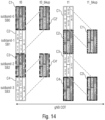
- Fig. 11 illustrates an embodiment in which Fig. 11(a) shows a configuration of the CORESETs as explained above with reference to Fig. 10 .
- Fig. 11 assumes a wideband operation, either in the licensed spectrum, in the unlicensed spectrum or in the licensed/unlicensed spectrum.
- each of the search spaces SS0 to SS4 in the CORESETS C1 to C4 of a group may be associated with a number of PDCCH candidates for respective aggregation levels, AL.
- the aggregation level is a property of the PDCCH.
- a CORESET may include PDCCHs with different ALs.
- the search space configuration tells the UE to look for how many PDCCH candidates with a certain AL, e.g. SS1: (AL-1: 0, AL-2: 4, AL-4:2). In this case the UE looks for this SS for 0 AL-1s, 4 AL-2s and 2 AL-4s.
- the UE does not expect control information for itself in the CORESETs of the group with another AL. In other words, the UE continues to looks only for this AL in the same and the other CORESETs of the same group at least for this specific DCI format.
- the embodiment of Fig. 11 is equally applicable for a single-band operation.
- This embodiment is, however, not limited to CORESET grouping, rather it may also be employed when applying search space grouping.
- the UE successfully finds a PDCCH in a search space the UE does not expect control information for itself in a search space with another AL. In other words, the UE continues to look only for the same AL in this and the other search spaces which are associated to the same group.
- Fig. 11(a) illustrates that the LBT procedure was successful for each subband being in the unlicensed spectrum.
- the UE if the UE successfully decodes the PDCCH in SS3 in subband SB0, the UE only decodes the PDCCH at the corresponding locations or search spaces SS1 in the other subbands. Thereby, the search space is reduced and, in turn, the number of blind decoding attempts thereby reducing power consumption and increasing energy efficiency at the UE.
- the search space is reduced and, in turn, the number of blind decoding attempts thereby reducing power consumption and increasing energy efficiency at the UE.
- Fig. 11(b) illustrates the LBT procedure was only successful for subband SB0 and subband SB2, but was not successful for subband SB1 and SB3.
- Fig. 11(b) only CORESETs C1 and C3 in subbands SB0 and SB2 are transmitted.
- the UE successfully decodes the PDCCH in SS3 in subband SB0 at the CORESET C01, due to the fact that subbands SB1 and SB3 are not carrying information, only the corresponding location or search space SS3 in subband SB2 in CORESET C21 is decoded.
- the wideband operation may be a NR-U wideband operation at least partially in the unlicensed spectrum, so that each subband in the unlicensed spectrum an LBT-procedure is to be carried out so as to see as to whether a transmission on the subband is possible or not.
- a transmissions may be performed by a gNB during the channel occupancy time, COT.
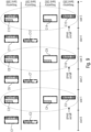
- Fig. 12 assumes the same configuration as explained above with reference to Fig. 10 and Fig. 11 and, in accordance with embodiments, the consistency of the configuration is not only across the subbands as described above with reference to Fig. 10 and Fig.
- Fig. 12 illustrates an embodiment in accordance with which the CORESET or search space configuration may be consistent across a gNB COT, and the one or more CORESETs carrying the control information for the UEs are transmitted once or several times during the COT, as is illustrated in Fig. 12 at the respective instances t0, t1, t2 and t3 that are within the illustrated gNB COT.
- the UE successfully decodes its PDCCH in SS1 of subband SB1 at time t0 its PDCCH is received at the same location or search space SS1 at times t1, t2 and t3.
- the LBT procedure fails one or more of the subbands as is illustrated at times t1, t2 and t3 so that during the gNB COT at times t1, t2 and t3 transmissions occur only on subbands SB0, SB2, SB1, SB3 and SB0, respectively.
- the UE may look into the corresponding location or search space in another subband. For example, in Fig. 12 , when the UE performs a successful decoding of the PDCCH at t0 in search space SS4 in subband SB1, the UE may continue to receive the scheduling for subsequent times in the same location or search space in the same subband.
- the UE in view of the group information it has for the respective CORESETs, may derive the scheduling information or control information from SS4 in C1 in the subband SB0 and from SS4 in subband SB2 for which the LBT procedure has been successful.
- an explicit relationship between CORESETs of a group may be provided.
- the transmitter may include into the respective CORESETs, for example starting from an initial or a default CORESET, further information indicating the other CORESETs transmitted in the other frequency bands and/or at a later time which include search spaces carrying control information for the receiving UE.
- the location of the corresponding control information in another CORESET of a group may be included, for example in the form of DCI information, so that the UE does not expect its control information in other CORESETs.
- the UE may skip those search spaces within the group which do not include information for it, e.g., control information or PDCCH candidates.
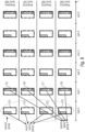
- Fig. 13 schematically illustrates the signaling of control information locations for a specific UE.
- the search spaces that are illustrated by the differently shaded rectangular portions of the CORESETs C1 to C4 may include, in addition to the PDCCH candidates for the receiving UE, also additional information, for example in the DCI, pointing to search spaces in other CORESETs of the CORESET group that are located in other subbands.
- the UE may be configured with a set of CORESETs out of which a group, also referred to as a subset, falls into the same time window, e.g. the same slot. Normally, the UE blind decodes on all of the CORSETs in this subset in this slot.
- the control information in accordance with this embodiment which may be present in some or all of the CORSETs, indicates in which of the CORSETs out of the set or out of the subset or in which of the subbands, there exists valid control information for that specific UE (the receiving UE) in this slot. So the UE may skip not indicated CORSETs although it is configured with them.
- Fig. 13 at time t0 the explicit indication of additional PDCCH information in other subbands is indicated. It is assumed that among the CORESETs C1 to C4 forming the CORESET group only search spaces SS1 and SS2 in CORESETs C1 and C2 hold information for the receiving UE so that either one or both of the CORESETs C1, C2 may include respective DCI information pointing towards the locations where additional PDCCH candidates for the receiving UE may be found, in the example of Fig. 13 , the search spaces SS1 and SS2. Naturally, other search spaces in the same or different CORESETs may also be signaled.
- the information provided, for example, in the DCI may point to the exact time-frequency resources in the subbands as indicated in Fig. 13 for the receiving UE to decode the other PDCCH(s).
- the pointing may only be to the CORESET holding additional information.
- the UE may assume that the control information decoded at the time-frequency resources in the first CORESET may be found at the corresponding time-frequency resources in the CORESET to which the UE is directed for further PDCCH candidates. This reduces the number of bits to be transmitted for signaling the locations where the additional PDCCH information for the receiving UE may be found.
- a bitmap of the subbands or the CORESETs may be provided. For example, in case of five subbands, five bits may be added to a DCI and the least significant bit may point to the lowest subband, and the most significant bit may point to the highest subband or vice versa.
- the present invention is not limited to the explicit relationship between CORESETs of a group, rather, the signaling of an explicit relationship between CORESETs may also be applied when no CORESET/search space grouping is employed.
- the UE that is served by the gNB uses a plurality of subbands for a communication with one or more entities, like other UE(s) or other gNB(s), in the wireless communication system.
- one or more or all of the plurality of subbands include one or more CORESETs carrying control information, e.g., DCI(s), for the UE, and some or all of the CORSETs indicate in which of the CORSETs control information for the respective UE is present.
- control information e.g., DCI(s)
- Fig. 13 is equally applicable for a single-band operation or for a multi-band operation in the licensed spectrum.
- Fig. 13 further illustrates an embodiment according to which the transmission of the CORESETs over the multiple subbands SB0 to SB3 within a gNB COT in case of using one or more bands in the unlicensed spectrum for the multi-subband operation or a wideband operation.
- An LBT procedure for allowing a communication of the respective subbands may fail so that certain subbands may not be used for a communication.
- Fig. 13 at times t1, t2 and t3 situations are illustrated in which the second and third subbands SB1, SB3, the first and third subbands SB0, SB2 and the last two subbands SB2 and SB4, respectively, may not be used because an LBT procedure fails.
- the additional information may be employed for pointing towards other search spaces within CORESETs of the group being located in different subbands. For example, as is illustrated in Fig. 13 at time t1 by the respective arrows pointing from a search space SS1 in CORESET C1 in subband SB0 to a search space SS2 it is indicated in SS1 that SS2 in SB2 holds PDCCH candidates for the receiving UE in CORESET C3 of the same group.
- the CORESETs or the search spaces of a group may be tied to an explicit or implicit prioritization or ranking which may be indicated by the transmitter, like the gNB or the transmitting UE, when configuring the receiving UE with a CORESET or search space configuration.
- the UE may perform blind decoding in the order of the prioritization/ranking of the CORESETs or search spaces of a group.
- applying the prioritization/ranking allows latency-critical assignments or grants in the high-ranked CORESETs or search spaces to speed up the detection of the PDCCHs.
- a priority/rank field may be added to the CORESET or search space signaling, for example in the above-described fields of the CORESET or search space configuration.
- the PUSCH preparation time is composed of the maximum required time to successfully decode a PDCCH and further preparations, such as L2 preparations.
- the maximum required time to successfully decode a PDCCH may be reduced for the highest ranked CORESET, which is the CORESET that is decoded first and, hence, the PUSCH preparation time may be assumed to be smaller for these uplink grants when compared to uplink grants in the following CORESETs.
- the DCI may be used to indicate the presence or absence of a DCI for the receiving UE in the frequency (in case of a single-band operation) or in one or more of the plurality of frequency bands (in case of a multi-band operation).
- additional bits or information may be needed to be put in the DCI. With the grouping, the additional information amount in the DCI may be lower.
- the blind decoding attempts are distributed equally or unequally among the frequency bands or the CORESETs of a group or the search spaces of a group taking into considerations the limitations of the number of blind decoding attempts as defined, for example, in Release-15 based on the subcarrier spacing per slot per serving cell, as shown in the table below (e.g., as in TS 38.213, V15.5.0, Table 10.1-2): ⁇ Maximum number of monitored PDCCH candidates per slot and per serving cell M PDCCH max , slot , ⁇ 0 44 1 36 2 22 3 20
- a search space configuration may be copied within a CORESET group.
- the search space configuration may can be configured only once for a group. Therefore, the search space configuration (or parts of it) of a default CORESET may also applied to the other CORESETs of the same CORESET group.
- the indication of the default CORESET may be explicit, for example by the gNB, or implicit by the order of configuring the CORESETs, e.g., the search space configuration of the first configured CORESET of that group, or the search space configuration of the CORESET having the lowest or highest CORESET ID may be used and copied.
- one or more CORESET configurations maybe confined within a subband, like an LBT subband, and the same pattern or configuration is replicated for the further frequency domain monitoring locations in different subbands, like other LBT subbands.
- a default CORSET configuration received for one subband may be used in one or more other subbands. For example, only a frequency information need to be changed in the default configuration to use it in another subband.
- the UE may restrict decoding of CORESETs to those actually being transmitted and carrying control information for the receiving UE.
- the UE may also be configured, for example via RRC configuration or reconfiguration, to monitor only a subset of the frequency bands for the PDCCH channel.
- the UE may be configured to monitor only a continuous frequency range at least for the duration of the CORESETs.
- a timer may be provided that starts at the end of the CORESETs. After the timer passed the UE may receive UL grants or DL assignments which are located within the whole of the one or more neighboring frequency bands.
- the search space configuration or the CORESET configuration as provided to the receiving UE may include a control rest set ID monitor field indicating the actual CORESETs to be monitored, for example by specifying them using the control resource set ID.
- the CORESET(s) monitoring may be a part of the CORESET config in the RRC message, and an example for such an the RRC message is given below:
- the CORESET(s) monitoring may be a part of the SearchSpace config in the RRC message, and an example for such an the RRC message is given below:
- the advantage of restricting the decoding of CORESETs is that the search space of the UE is narrowed down because search spaces in the CORESETs are avoided for which the transmitter, like the gNB, did not provide any control information for the receiving UE.
- the UE may be set up or configured with two CORESETs C1, C3, i.e., the UE performs a blind decoding on CORESETs C1, C3.
- the UE performs a blind decoding on only one of these CORESETs C1, C3 as the location of the second PDCCH, in case the first PDCCH decoding was successful, is implicitly known.
- the UE does not perform a blind decoding or detection of a CORESET on this subband as the UE first of all checks the result of the LBT, for example, through DMRS decorrelation.
- the blind decoding for search spaces or CORESETs in subbands in which LBT has failed is deactivated.
- Assigning, e.g., though an RRC message, CORESETs to monitor allows for obtaining a desired distribution of CORESETs for one or more different UEs across the given frequency bands by the gNB thereby achieving, for example, load balancing.
- the assignment of each CORESET with a CORESET ID enables the UEs, i.e., those receiving UEs served by the transmitter, to be set up such that they only monitor a particular set of CORESET IDs.
- a simple relationship between the CORESET ID and the number of active frequency bands, N_ASB may help in redistributing the UEs across the successful frequency bands.
- each frequency band is used for X UEs.
- N_ASB 2
- a modulo operation may be performed, i.e., CORESET_ID % N_ASB so as to redistribute the UEs so that 2X UEs are in one frequency band and 2X UEs are in another frequency band.
- search space candidates may be redistributed. For example, in case of using one or more bands in the unlicensed spectrum, search space candidates may be distributed or redistributed among the available subbands which have passed their LBT result. This enables the gNB to be more flexible in scheduling and to better adapt to the LBT results.
- the distribution/redistribution of the search spaces may be valid for all CORESETs except an initial or default CORESET so as to give the gNB enough time to execute the distribution or redistribution.
- the distribution/redistribution may be based on an RRC configuration that indicates or fixes the number of candidates dependent on the number of subbands that passed the LBT.
- a formula-based approach may be employed, in accordance with which the UE may calculate the number of candidates in the subbands that passed the LBT.
- Fig. 14 illustrates an embodiment for providing backup CORESETs to be used within a gNB COT.
- some or more of the bands may not pass the LBT procedure and, therefore, are not available for transmitting control information by the transmitting entity, like the gNB or another UE, towards the receiving UE.
- backup CORESETs may be provided in some or all of the subbands to be transmitted. For example, as is depicted Fig. 14 , for each of the CORESETs C1 to C4 respective backup CORESETs C1' to C4' are provided in different subbands.
- backup CORESETs are provided within the gNB COT in the subbands where the LBT result is successful for the subbands that failed the LBT.
- the indication of the backup locations is either preconfigured in an RRC message with an activation/deactivation based on physical signaling or transmission, like in the DCI, or is dynamically allocated and communicated the DCIs. This allows the gNB to schedule more UEs over the LBT successful subbands and helps reducing latency.
- Fig. 14 illustrates an example for the use of backup CORESETs, and at time t0 the failure of the LBT result for subband SB1 and subband SB3 results in resources being assigned in time t0:bkup on subband SB0 and SB2.
- the receiving UE recognizing that there was no transmission on subband SB1 and SB3 may recognize from its pre-configuration or from the signaling in the received control information in CORESET C1 and CORESET C3 that the backup CORESET may be found in subbands SB0, SB2 at the indicated positions so that the further control information, like further PDCCH(s) may be decoded from the backup CORESETs.
- a similar situation is assumed, however, a failure of subband SB0 and SB2 which results in providing the backup CORESETs C1' and C3' in subbands SB1 and SB3.
- the UE may employ one or more backup CORESETs responsive to the UE not detecting the presence of a CORESET in a subband, e.g., due to a LBT failure or due to the gNB not transmitting the CORESET, and/or responsive to the UE not decoding any control information from any of the subbands.
- backup CORESETs may also be provided in the licensed spectrum so as to allow decoding the control information in case the UE does not successfully decode the control information from one or more CORESETs.
- the UE may use the backup CORESET(s) at a different frequency resource and/or time resource in which a decoding is successful.
- the different frequency resource and/or time resource may be within the same frequency band or within the different frequency bands
- a CORESET may be restricted to borders between adjacent frequency bands, e.g. subband borders in case of NR-U.
- This approach applies equally for approaches not employing CORESET or search space grouping and for approaches employing CORESET or search space grouping.
- Some or all of the frequency bands may be in the unlicensed spectrum.
- Fig. 15 illustrates schematically an embodiment restricting the search space to frequency band borders.
- the search space may span 20 MHz, and in Fig.
- search spaces 00 to 11 are indicated which are located at resources in the respective frequency bands SB1 and SB2 that are at the borders of the frequency bands SB1 and SB2, i.e., the search spaces 00, 10 and the search spaces 01, 11, respectively, span a consecutive frequency range in both frequency bands.
- other search spaces may be provided at other locations in a frequency band, like in the embodiments described above.
- Fig. 15 further illustrates search spaces 21 to 31 are indicated which are located at resources at the borders of frequency bands SB3 and SB4.
- a UE that decodes multiple frequency bands performs a blind decoding only on a limited bandwidth, like the 20 MHz indicated in Fig. 15 .
- a limited bandwidth like the 20 MHz indicated in Fig. 15 .
- decoding the full bandwidth of the two frequency bands SB1 and SB2 for example, instead of decoding 40 MHz bandwidths, only the smaller bandwidth is to be considered.
- the placement of the search spaces as described above may be preconfigured so that the UE may always perform a blind decoding on two or four or more neighboring frequency bands simultaneously depending on the UEs RF capabilities. Further, the UE may be configured to monitor only the core bandwidths and does not expect to receive any PDCCH information outside the CORESET bandwidths, at least for the duration of the CORESET or for the duration of a pre-configured timer.
- a communication is between a transmitter, like a gNB or a UE, and a receiver, like a UE and a gNB.
- the invention is not limited to such a communication, rather, the above-described principles may equally be applied for a device-to-device communication, like a D2D, V2V, V2X communication.
- the communication is over a sidelink between the respective devices.
- the transmitter is a first UE and the receiver is a second UE communicating using the sidelink resources.
- the wireless communication system may include a terrestrial network, or a non-terrestrial network, or networks or segments of networks using as a receiver an airborne vehicle or a spaceborne vehicle, or a combination thereof.
- AP Access Point
- a base station may comprise one or more of a macro cell base station, or a small cell base station, or a spaceborne vehicle, like a satellite or a space, or an airborne vehicle, like a unmanned aircraft system (UAS), e.g., a tethered UAS, a lighter than air UAS (LTA), a heavier than air UAS (HTA) and a high altitude UAS platforms (HAPs), or any transmission/reception point (TRP) enabling an item or a device provided with network connectivity to communicate using the wireless communication system, or a Wifi AP STA, e.g. 802.11ax or 802.11be.
- UAS unmanned aircraft system
- LTA lighter than air UAS
- HTA heavier than air UAS
- HAPs high altitude UAS platforms
- TRP transmission/reception point
- aspects of the described concept have been described in the context of an apparatus, it is clear that these aspects also represent a description of the corresponding method, where a block or a device corresponds to a method step or a feature of a method step. Analogously, aspects described in the context of a method step also represent a description of a corresponding block or item or feature of a corresponding apparatus.
- Various elements and features of the present invention may be implemented in hardware using analog and/or digital circuits, in software, through the execution of instructions by one or more general purpose or special-purpose processors, or as a combination of hardware and software.
- embodiments of the present invention may be implemented in the environment of a computer system or another processing system.
- Fig. 16 illustrates an example of a computer system 500.
- the units or modules as well as the steps of the methods performed by these units may execute on one or more computer systems 500.
- the computer system 500 includes one or more processors 502, like a special purpose or a general-purpose digital signal processor.
- the processor 502 is connected to a communication infrastructure 504, like a bus or a network.
- the computer system 500 includes a main memory 506, e.g., a random-access memory (RAM), and a secondary memory 508, e.g., a hard disk drive and/or a removable storage drive.
- the secondary memory 508 may allow computer programs or other instructions to be loaded into the computer system 500.
- the computer system 500 may further include a communications interface 510 to allow software and data to be transferred between computer system 500 and external devices.
- the communication may be in the from electronic, electromagnetic, optical, or other signals capable of being handled by a communications interface.
- the communication may use a wire or a cable, fiber optics, a phone line, a cellular phone link, an RF link and other communications channels 512.
- computer program medium and “computer readable medium” are used to generally refer to tangible storage media such as removable storage units or a hard disk installed in a hard disk drive.
- These computer program products are means for providing software to the computer system 500.
- the computer programs also referred to as computer control logic, are stored in main memory 506 and/or secondary memory 508. Computer programs may also be received via the communications interface 510.
- the computer program when executed, enables the computer system 500 to implement the present invention.
- the computer program when executed, enables processor 502 to implement the processes of the present invention, such as any of the methods described herein. Accordingly, such a computer program may represent a controller of the computer system 500.
- the software may be stored in a computer program product and loaded into computer system 500 using a removable storage drive, an interface, like communications interface 510.
- the implementation in hardware or in software may be performed using a digital storage medium, for example cloud storage, a floppy disk, a DVD, a Blue-Ray, a CD, a ROM, a PROM, an EPROM, an EEPROM or a FLASH memory, having electronically readable control signals stored thereon, which cooperate (or are capable of cooperating) with a programmable computer system such that the respective method is performed. Therefore, the digital storage medium may be computer readable.
- a digital storage medium for example cloud storage, a floppy disk, a DVD, a Blue-Ray, a CD, a ROM, a PROM, an EPROM, an EEPROM or a FLASH memory, having electronically readable control signals stored thereon, which cooperate (or are capable of cooperating) with a programmable computer system such that the respective method is performed. Therefore, the digital storage medium may be computer readable.
- Some embodiments according to the invention comprise a data carrier having electronically readable control signals, which are capable of cooperating with a programmable computer system, such that one of the methods described herein is performed.
- embodiments of the present invention may be implemented as a computer program product with a program code, the program code being operative for performing one of the methods when the computer program product runs on a computer.
- the program code may for example be stored on a machine readable carrier.
- inventions comprise the computer program for performing one of the methods described herein, stored on a machine readable carrier.
- an embodiment of the inventive method is, therefore, a computer program having a program code for performing one of the methods described herein, when the computer program runs on a computer.
- a further embodiment of the inventive methods is, therefore, a data carrier (or a digital storage medium, or a computer-readable medium) comprising, recorded thereon, the computer program for performing one of the methods described herein.
- a further embodiment of the inventive method is, therefore, a data stream or a sequence of signals representing the computer program for performing one of the methods described herein. The data stream or the sequence of signals may for example be configured to be transferred via a data communication connection, for example via the Internet.
- a further embodiment comprises a processing means, for example a computer, or a programmable logic device, configured to or adapted to perform one of the methods described herein.
- a further embodiment comprises a computer having installed thereon the computer program for performing one of the methods described herein.
- a programmable logic device for example a field programmable gate array
- a field programmable gate array may cooperate with a microprocessor in order to perform one of the methods described herein.
- the methods are preferably performed by any hardware apparatus.
Landscapes
- Engineering & Computer Science (AREA)
- Signal Processing (AREA)
- Computer Networks & Wireless Communication (AREA)
- Mobile Radio Communication Systems (AREA)
Claims (15)
- Ein Nutzergerät, UE, (3021, 3022) für ein Drahtloskommunikationssystem (100),wobei das UE (3021, 3022) dazu dient, von einer Basisstation (300) bedient zu werden, und dazu dient, ein oder mehrere Frequenzbänder für eine Kommunikation mit einer oder mehreren Einheiten des Drahtloskommunikationssystems (100) zu verwenden, wobei eines oder mehrere oder alle der Frequenzbänder eine Mehrzahl von Steuerressourcensätzen, CORESETs (C1-C16), umfassen, wobei jeder CORESET (C1-C16) einen oder mehrere Suchräume (SS1-SS4) umfasst, die Steuerinformationen tragen,wobei das UE (3021, 3022) dazu dient, Folgendes zu gruppieren:• einige oder alle der CORESETs (C1-C16) in jeweilige CORESET-Gruppen, oder• einige oder alle der Suchräume (SS1-SS4) in jeweilige Suchraumgruppen,wobei eine CORESET-Gruppe einige oder alle CORESETs (C1-C16) innerhalb eines bestimmten Zeitfensters umfasst, und wobei eine Suchraumgruppe einige oder alle Suchräume (SS1-SS4) innerhalb des bestimmten Zeitfensters umfasst,wobei die CORESES oder die Suchräume (SS1-SS4) gemäß Folgendem gruppiert werden:• einer oder mehreren Gruppenidentifikationen, IDs, mit denen das UE (3021, 3022) konfiguriert ist, wobei jede Gruppen-ID auf eine CORESET-Gruppe oder eine Suchraumgruppe zeigt oder diese angibt, und/oder• einer Bestimmung, dass sich CORESETs (C1-C16) oder Suchräume (SS1-SS4) innerhalb des gleichen Zeitfensters befinden,dadurch gekennzeichnet, dass das UE (3021, 3022) dazu dient, die CORESETs (C1-C16) oder die Suchräume (SS1-SS4) einer Gruppe zu verketten oder zu kombinieren, wodurch ein virtueller CORESET oder ein virtueller Suchraum definiert wird, und wobei das UE (3021, 3022) dazu dient, blindes Decodieren zu stoppen, sobald eine bestimmte Anzahl von Steuerparametern innerhalb des virtuellen Suchraums oder des virtuellen CORESET gefunden wurde.
- Das Nutzergerät, UE, (3021, 3022) gemäß Anspruch 1, wobeidas UE (3021, 3022) dazu dient, ein Frequenzband für die Kommunikation zu verwenden, und eine CORESET-Gruppe / Suchraumgruppe einige oder alle CORESETs / Suchräume in dem einen Frequenzband umfasst, die innerhalb eines bestimmten Zeitfensters bereitgestellt sind, oderdas UE (3021, 3022) dazu dient, eine Mehrzahl von Frequenzbändern für die Kommunikation zu verwenden, und eine CORESET-Gruppe / Suchraumgruppe einige oder alle CORESETs / Suchräume in einem oder mehreren oder allen der Mehrzahl von Frequenzbändern umfasst, die innerhalb eines bestimmten Zeitfensters bereitgestellt sind.
- Das Nutzergerät, UE, (3021, 3022) gemäß Anspruch 1 oder 2, wobei das bestimmte Zeitfenster einen oder mehrere Schlitze oder eine Mehrzahl von aufeinanderfolgenden Symbolen aufweist.
- Das Nutzergerät, UE, (3021, 3022) gemäß einem der Ansprüche 1 bis 3, wobei das UE dazu dient, mit einem CORESET-Gruppeninformationselement konfiguriert zu werden, wobei das CORESET-Gruppeninformationselement CORESET-Konfigurationen angibt, die für die Gruppierung zu berücksichtigen sind.
- Das Nutzergerät, UE, (3021, 3022) gemäß einem der Ansprüche 1 bis 4, wobei das UE dazu dient, mit einem oder mehreren CORESET-Informationselementen (ControlResourceSet) konfiguriert zu werden, wobei ein CORESET-Informationselement die Gruppen-ID (grouplndex) umfasst, um anzugeben, welche CORESET-Konfigurationen für die Gruppierung zu berücksichtigen sind.
- Das Nutzergerät, UE, (3021, 3022) gemäß einem der Ansprüche 1 bis 5, wobei das UE dazu dient, mit einem Suchraumgruppeninformationselement konfiguriert zu werden, wobei das Suchraumgruppeninformationselement Suchräume (SS1-SS4) und zugehörige CORESETs (C1-C16) angibt, die Teil der gleichen Suchraumgruppe sind.
- Das Nutzergerät, UE, (3021, 3022) gemäß einem der Ansprüche 1 bis 6, wobei das UE dazu dient, mit einem oder mehreren CORESET-Informationselementen (ControlResourceSet) und einem oder mehreren Suchrauminformationselementen (SearchSpace) konfiguriert zu werden, wobei ein Suchrauminformationselement ein Suchraumgruppenangabeelement (searchSpaceGroup) umfasst, das die Gruppen-ID (grouplndex) umfasst.
- Das Nutzergerät, UE, (3021, 3022) gemäß einem der Ansprüche 1 bis 7, wobei das UE dazu dient, mit einem Parameter konfiguriert zu werden, der die Gruppierung aktiviert oder deaktiviert.
- Das Nutzergerät, UE, (3021, 3022) gemäß einem der Ansprüche 1 bis 8, wobei das UE dazu dient, das Decodieren der Steuerinformationen für das UE (3021, 3022) aus den Suchräumen (SS1-SS4) unter Verwendung der Gruppierung zu koordinieren, wobei das Decodieren blindes Decodieren umfassen kann.
- Das Nutzergerät, UE, (3021, 3022) gemäß einem der Ansprüche 1 bis 9, wobei das UE dazu dient, eine Standard-CORESET-Konfiguration für eine Gruppe zu empfangen und die übrigen CORESETs der Gruppe gemäß der Standard-CORESET-Konfiguration zu konfigurieren.
- Das Nutzergerät, UE, (3021, 3022) gemäß Anspruch 10, wobei, um den einen oder die mehreren CORESETs (C1-C16) zu konfigurieren, das UE dazu dient, zumindest einen Teil einer Suchraumkonfiguration des Standard-CORESET auf die anderen CORESETs der gleichen Gruppe anzuwenden.
- Das Nutzergerät, UE, (3021, 3022) gemäß Anspruch 10 oder 11, wobei die Standard-CORESET-Konfiguration wie folgt angegeben wird:• explizit durch die Basisstation (300); oder• implizit durch eine erste empfangene CORESET-Konfiguration oder durch eine CORESET-Konfiguration mit einer bestimmten CORESET-ID.
- Ein Drahtloskommunikationssystem (100), das folgende Merkmale aufweist:ein oder mehrere Nutzergeräte, UEs, gemäß einem der Ansprüche 1 bis 12, undeine oder mehrere Basisstationen (300).
- Ein Verfahren zum Betreiben eines Drahtloskommunikationssystems (100),wobei ein Nutzergerät, UE, (302i, 3022) von einer Basisstation (300) bedient wird und ein oder mehrere Frequenzbänder für eine Kommunikation mit einer oder mehreren Einheiten des Drahtloskommunikationssystems (100) verwendet, wobei eines oder mehrere oder alle der Frequenzbänder einen oder mehrere Steuerressourcensätze, CORESETs (C1-C16), umfassen, wobei jeder CORESET (C1-C16) einen oder mehrere Suchräume (SS1-SS4) umfasst, die Steuerinformationen tragen,wobei das Verfahren ein Gruppieren einiger oder aller der CORESETs (C1-C16) in jeweilige CORESET-Gruppen oder einiger oder aller der Suchräume (SS1-SS4) in jeweilige Suchraumgruppen aufweist,wobei eine CORESET-Gruppe einige oder alle CORESETs (C1-C16) innerhalb eines bestimmten Zeitfensters umfasst, und wobei eine Suchraumgruppe einige oder alle Suchräume (SS1-SS4) innerhalb des bestimmten Zeitfensters umfasst, undwobei das Gruppieren auf Folgendes anspricht:• eine oder mehrere Gruppen-IDs, mit denen das UE (3021, 3022) konfiguriert ist, wobei jede Gruppen-ID auf eine CORESET-Gruppe oder eine Suchraumgruppe zeigt oder diese angibt, und/oder• eine Bestimmung, dass sich CORESETs (C1-C16) oder Suchräume (SS1-SS4) innerhalb des gleichen Zeitfensters befinden,dadurch gekennzeichnet, dass das UE (3021, 3022) die CORESETs (C1-C16) oder die Suchräume (SS1-SS4) einer Gruppe verkettet oder kombiniert, wodurch ein virtueller CORESET oder ein virtueller Suchraum definiert wird, undwobei das UE (3021, 3022) dazu dient, blindes Decodieren zu stoppen, sobald eine bestimmte Anzahl von Steuerparametern innerhalb des virtuellen Suchraums oder des virtuellen CORESET gefunden wurde.
- Ein Computerprogrammprodukt, das Anweisungen aufweist, die, wenn das Programm durch einen Computer ausgeführt wird, den Computer dazu veranlassen, das Verfahren gemäß Anspruch 14 auszuführen.
Priority Applications (1)
| Application Number | Priority Date | Filing Date | Title |
|---|---|---|---|
| EP24219451.2A EP4535711A3 (de) | 2019-07-23 | 2020-07-08 | Coreset-gruppierung |
Applications Claiming Priority (3)
| Application Number | Priority Date | Filing Date | Title |
|---|---|---|---|
| EP19187864 | 2019-07-23 | ||
| EP19207928 | 2019-11-08 | ||
| PCT/EP2020/069305 WO2021013554A1 (en) | 2019-07-23 | 2020-07-08 | Coreset grouping |
Related Child Applications (1)
| Application Number | Title | Priority Date | Filing Date |
|---|---|---|---|
| EP24219451.2A Division EP4535711A3 (de) | 2019-07-23 | 2020-07-08 | Coreset-gruppierung |
Publications (2)
| Publication Number | Publication Date |
|---|---|
| EP4005131A1 EP4005131A1 (de) | 2022-06-01 |
| EP4005131B1 true EP4005131B1 (de) | 2024-12-18 |
Family
ID=71452249
Family Applications (2)
| Application Number | Title | Priority Date | Filing Date |
|---|---|---|---|
| EP20736357.3A Active EP4005131B1 (de) | 2019-07-23 | 2020-07-08 | Coreset-gruppierung |
| EP24219451.2A Pending EP4535711A3 (de) | 2019-07-23 | 2020-07-08 | Coreset-gruppierung |
Family Applications After (1)
| Application Number | Title | Priority Date | Filing Date |
|---|---|---|---|
| EP24219451.2A Pending EP4535711A3 (de) | 2019-07-23 | 2020-07-08 | Coreset-gruppierung |
Country Status (6)
| Country | Link |
|---|---|
| US (2) | US12126562B2 (de) |
| EP (2) | EP4005131B1 (de) |
| JP (1) | JP7383789B2 (de) |
| KR (1) | KR20220033056A (de) |
| CN (1) | CN114450908B (de) |
| WO (1) | WO2021013554A1 (de) |
Families Citing this family (6)
| Publication number | Priority date | Publication date | Assignee | Title |
|---|---|---|---|---|
| KR20250084249A (ko) * | 2019-07-25 | 2025-06-10 | 프라운호퍼 게젤샤프트 쭈르 푀르데룽 데어 안겐반텐 포르슝 에. 베. | 송신기 cot 내에서 구성된 승인 |
| WO2021072759A1 (zh) * | 2019-10-18 | 2021-04-22 | 华为技术有限公司 | 一种通信方法及装置 |
| WO2021262891A2 (en) * | 2020-06-24 | 2021-12-30 | Qualcomm Incorporated | Non-orthogonal and orthogonal reservation signals |
| US12501431B2 (en) * | 2020-11-18 | 2025-12-16 | Nvidia Corporation | Control data bandwidth allocation for fifth generation (5G) new radio communications |
| US11943159B2 (en) * | 2022-04-14 | 2024-03-26 | Qualcomm Incorporated | Reference signal mapping |
| WO2026059365A1 (ko) * | 2024-09-13 | 2026-03-19 | 엘지전자 주식회사 | Pdcch의 송수신을 위한 제어 자원의 설정 방법 및 그 장치 |
Family Cites Families (21)
| Publication number | Priority date | Publication date | Assignee | Title |
|---|---|---|---|---|
| US7856572B2 (en) * | 2004-11-17 | 2010-12-21 | Nec Corporation | Information processing device, program thereof, modular type system operation management system, and component selection method |
| SI2446685T1 (sl) * | 2009-06-25 | 2019-03-29 | Koninklijke Philips N.V. | Postopek za komunikacijo v mobilnem omrežju |
| US10079658B2 (en) * | 2011-11-04 | 2018-09-18 | Qualcomm Incorporated | Search space design for e-PDCCH in wireless communication networks |
| EP3148242A4 (de) * | 2014-06-20 | 2017-04-19 | Huawei Technologies Co. Ltd. | Datenübertragungsverfahren und -vorrichtung |
| US10631280B2 (en) * | 2016-11-03 | 2020-04-21 | Telefonaktiebolaget Lm Ericsson (Publ) | Variable subband configuration of search space |
| US11523376B2 (en) * | 2017-01-05 | 2022-12-06 | Huawei Technologies Co., Ltd. | Method for downlink control channel design |
| US10631178B2 (en) | 2017-02-06 | 2020-04-21 | Qualcomm Incorporated | Control resource set group design for improved communications devices, systems, and networks |
| US10567058B2 (en) * | 2017-02-08 | 2020-02-18 | Samsung Electronics Co., Ltd. | Method and apparatus for beam management |
| CN108633052B (zh) * | 2017-03-24 | 2023-09-26 | 中兴通讯股份有限公司 | 一种资源配置方法、装置和设备 |
| US10912111B2 (en) | 2017-05-04 | 2021-02-02 | Samsung Electronics Co., Ltd. | Method and apparatus for transmitting remaining minimum system information in multibeam-based system |
| CN109121159B (zh) * | 2017-06-22 | 2021-04-23 | 维沃移动通信有限公司 | 盲检能力上报方法、盲检配置、盲检方法、终端及基站 |
| CN109392140B (zh) * | 2017-08-11 | 2020-07-28 | 维沃移动通信有限公司 | 一种用于监听pdcch的方法、终端及网络设备 |
| CN109391971B (zh) * | 2017-08-11 | 2020-08-18 | 维沃移动通信有限公司 | 一种pdcch的搜索空间的配置、监听方法及设备 |
| CN111034287B (zh) | 2017-09-08 | 2023-08-22 | 富士通株式会社 | 资源配置方法、确定方法及其装置、通信系统 |
| US10973013B2 (en) * | 2017-11-15 | 2021-04-06 | Sharp Kabushiki Kaisha | User equipments, base stations and methods |
| EP3777284B1 (de) * | 2018-04-06 | 2024-12-04 | Nokia Technologies Oy | Breitbandiger pdcch für unlizenziertes band für new radio |
| CN111148260B (zh) * | 2018-11-02 | 2022-05-13 | 华为技术有限公司 | 发送和接收数据的方法以及通信装置 |
| CN111614434B (zh) * | 2019-02-25 | 2021-08-31 | 华为技术有限公司 | 搜索空间的盲检方法及通信装置 |
| US11997678B2 (en) * | 2019-04-04 | 2024-05-28 | Lg Electronics Inc. | Method for transmitting and receiving data in wireless communication system, and apparatus therefor |
| US11395283B2 (en) * | 2019-06-06 | 2022-07-19 | Samsung Electronics Co., Ltd. | Determination of search space sets for physical downlink control channel (PDCCH) monitoring |
| US10939428B2 (en) * | 2019-07-19 | 2021-03-02 | Qualcomm Incorporated | Techniques for limiting blind decoding for multi-DCI based multi-transmit-receive points |
-
2020
- 2020-07-08 EP EP20736357.3A patent/EP4005131B1/de active Active
- 2020-07-08 CN CN202080066648.2A patent/CN114450908B/zh active Active
- 2020-07-08 KR KR1020227005723A patent/KR20220033056A/ko active Pending
- 2020-07-08 WO PCT/EP2020/069305 patent/WO2021013554A1/en not_active Ceased
- 2020-07-08 EP EP24219451.2A patent/EP4535711A3/de active Pending
- 2020-07-08 JP JP2022504255A patent/JP7383789B2/ja active Active
-
2022
- 2022-01-20 US US17/580,449 patent/US12126562B2/en active Active
-
2024
- 2024-09-20 US US18/891,870 patent/US20250158779A1/en active Pending
Also Published As
| Publication number | Publication date |
|---|---|
| JP2022541619A (ja) | 2022-09-26 |
| EP4535711A2 (de) | 2025-04-09 |
| EP4005131A1 (de) | 2022-06-01 |
| US20220263630A1 (en) | 2022-08-18 |
| US12126562B2 (en) | 2024-10-22 |
| CN114450908B (zh) | 2024-07-30 |
| KR20220033056A (ko) | 2022-03-15 |
| EP4535711A3 (de) | 2025-06-11 |
| US20250158779A1 (en) | 2025-05-15 |
| CN114450908A (zh) | 2022-05-06 |
| WO2021013554A1 (en) | 2021-01-28 |
| JP7383789B2 (ja) | 2023-11-20 |
Similar Documents
| Publication | Publication Date | Title |
|---|---|---|
| US20240397483A1 (en) | Radio sidelink frame structure | |
| US12414141B2 (en) | NR V2X resource pool design | |
| EP4005131B1 (de) | Coreset-gruppierung | |
| US12101806B2 (en) | NR-U wideband enhancements | |
| US20220150968A1 (en) | Configured grants within a transmitter cot | |
| JP2023539223A (ja) | Ueカバレッジの拡張 | |
| US20240205948A1 (en) | Sidelink, sl, interlacing configurations | |
| US20250280435A1 (en) | Time gap adjustment for channel access procedure by user devices for a sidelink communication in an unlicensed spectrum | |
| WO2021028525A1 (en) | Apparatuses and methods for wireless communications | |
| US12273860B2 (en) | Wireless communication system having a specific sidelink frame structure |
Legal Events
| Date | Code | Title | Description |
|---|---|---|---|
| STAA | Information on the status of an ep patent application or granted ep patent |
Free format text: STATUS: UNKNOWN |
|
| STAA | Information on the status of an ep patent application or granted ep patent |
Free format text: STATUS: THE INTERNATIONAL PUBLICATION HAS BEEN MADE |
|
| PUAI | Public reference made under article 153(3) epc to a published international application that has entered the european phase |
Free format text: ORIGINAL CODE: 0009012 |
|
| STAA | Information on the status of an ep patent application or granted ep patent |
Free format text: STATUS: REQUEST FOR EXAMINATION WAS MADE |
|
| 17P | Request for examination filed |
Effective date: 20220118 |
|
| AK | Designated contracting states |
Kind code of ref document: A1 Designated state(s): AL AT BE BG CH CY CZ DE DK EE ES FI FR GB GR HR HU IE IS IT LI LT LU LV MC MK MT NL NO PL PT RO RS SE SI SK SM TR |
|
| DAV | Request for validation of the european patent (deleted) | ||
| DAX | Request for extension of the european patent (deleted) | ||
| GRAP | Despatch of communication of intention to grant a patent |
Free format text: ORIGINAL CODE: EPIDOSNIGR1 |
|
| STAA | Information on the status of an ep patent application or granted ep patent |
Free format text: STATUS: GRANT OF PATENT IS INTENDED |
|
| INTG | Intention to grant announced |
Effective date: 20240712 |
|
| GRAS | Grant fee paid |
Free format text: ORIGINAL CODE: EPIDOSNIGR3 |
|
| GRAA | (expected) grant |
Free format text: ORIGINAL CODE: 0009210 |
|
| STAA | Information on the status of an ep patent application or granted ep patent |
Free format text: STATUS: THE PATENT HAS BEEN GRANTED |
|
| P01 | Opt-out of the competence of the unified patent court (upc) registered |
Free format text: CASE NUMBER: APP_57348/2024 Effective date: 20241021 |
|
| AK | Designated contracting states |
Kind code of ref document: B1 Designated state(s): AL AT BE BG CH CY CZ DE DK EE ES FI FR GB GR HR HU IE IS IT LI LT LU LV MC MK MT NL NO PL PT RO RS SE SI SK SM TR |
|
| REG | Reference to a national code |
Ref country code: CH Ref legal event code: EP |
|
| REG | Reference to a national code |
Ref country code: DE Ref legal event code: R096 Ref document number: 602020043342 Country of ref document: DE |
|
| REG | Reference to a national code |
Ref country code: IE Ref legal event code: FG4D |
|
| REG | Reference to a national code |
Ref country code: NL Ref legal event code: FP |
|
| REG | Reference to a national code |
Ref country code: LT Ref legal event code: MG9D |
|
| PG25 | Lapsed in a contracting state [announced via postgrant information from national office to epo] |
Ref country code: HR Free format text: LAPSE BECAUSE OF FAILURE TO SUBMIT A TRANSLATION OF THE DESCRIPTION OR TO PAY THE FEE WITHIN THE PRESCRIBED TIME-LIMIT Effective date: 20241218 |
|
| PG25 | Lapsed in a contracting state [announced via postgrant information from national office to epo] |
Ref country code: FI Free format text: LAPSE BECAUSE OF FAILURE TO SUBMIT A TRANSLATION OF THE DESCRIPTION OR TO PAY THE FEE WITHIN THE PRESCRIBED TIME-LIMIT Effective date: 20241218 |
|
| PG25 | Lapsed in a contracting state [announced via postgrant information from national office to epo] |
Ref country code: BG Free format text: LAPSE BECAUSE OF FAILURE TO SUBMIT A TRANSLATION OF THE DESCRIPTION OR TO PAY THE FEE WITHIN THE PRESCRIBED TIME-LIMIT Effective date: 20241218 |
|
| PG25 | Lapsed in a contracting state [announced via postgrant information from national office to epo] |
Ref country code: NO Free format text: LAPSE BECAUSE OF FAILURE TO SUBMIT A TRANSLATION OF THE DESCRIPTION OR TO PAY THE FEE WITHIN THE PRESCRIBED TIME-LIMIT Effective date: 20250318 |
|
| PG25 | Lapsed in a contracting state [announced via postgrant information from national office to epo] |
Ref country code: LV Free format text: LAPSE BECAUSE OF FAILURE TO SUBMIT A TRANSLATION OF THE DESCRIPTION OR TO PAY THE FEE WITHIN THE PRESCRIBED TIME-LIMIT Effective date: 20241218 Ref country code: GR Free format text: LAPSE BECAUSE OF FAILURE TO SUBMIT A TRANSLATION OF THE DESCRIPTION OR TO PAY THE FEE WITHIN THE PRESCRIBED TIME-LIMIT Effective date: 20250319 |
|
| PG25 | Lapsed in a contracting state [announced via postgrant information from national office to epo] |
Ref country code: RS Free format text: LAPSE BECAUSE OF FAILURE TO SUBMIT A TRANSLATION OF THE DESCRIPTION OR TO PAY THE FEE WITHIN THE PRESCRIBED TIME-LIMIT Effective date: 20250318 |
|
| REG | Reference to a national code |
Ref country code: AT Ref legal event code: MK05 Ref document number: 1753112 Country of ref document: AT Kind code of ref document: T Effective date: 20241218 |
|
| PG25 | Lapsed in a contracting state [announced via postgrant information from national office to epo] |
Ref country code: SM Free format text: LAPSE BECAUSE OF FAILURE TO SUBMIT A TRANSLATION OF THE DESCRIPTION OR TO PAY THE FEE WITHIN THE PRESCRIBED TIME-LIMIT Effective date: 20241218 |
|
| PG25 | Lapsed in a contracting state [announced via postgrant information from national office to epo] |
Ref country code: PL Free format text: LAPSE BECAUSE OF FAILURE TO SUBMIT A TRANSLATION OF THE DESCRIPTION OR TO PAY THE FEE WITHIN THE PRESCRIBED TIME-LIMIT Effective date: 20241218 |
|
| PG25 | Lapsed in a contracting state [announced via postgrant information from national office to epo] |
Ref country code: ES Free format text: LAPSE BECAUSE OF FAILURE TO SUBMIT A TRANSLATION OF THE DESCRIPTION OR TO PAY THE FEE WITHIN THE PRESCRIBED TIME-LIMIT Effective date: 20241218 |
|
| PG25 | Lapsed in a contracting state [announced via postgrant information from national office to epo] |
Ref country code: IS Free format text: LAPSE BECAUSE OF FAILURE TO SUBMIT A TRANSLATION OF THE DESCRIPTION OR TO PAY THE FEE WITHIN THE PRESCRIBED TIME-LIMIT Effective date: 20250418 |
|
| PG25 | Lapsed in a contracting state [announced via postgrant information from national office to epo] |
Ref country code: PT Free format text: LAPSE BECAUSE OF FAILURE TO SUBMIT A TRANSLATION OF THE DESCRIPTION OR TO PAY THE FEE WITHIN THE PRESCRIBED TIME-LIMIT Effective date: 20250421 |
|
| PG25 | Lapsed in a contracting state [announced via postgrant information from national office to epo] |
Ref country code: EE Free format text: LAPSE BECAUSE OF FAILURE TO SUBMIT A TRANSLATION OF THE DESCRIPTION OR TO PAY THE FEE WITHIN THE PRESCRIBED TIME-LIMIT Effective date: 20241218 |
|
| PG25 | Lapsed in a contracting state [announced via postgrant information from national office to epo] |
Ref country code: RO Free format text: LAPSE BECAUSE OF FAILURE TO SUBMIT A TRANSLATION OF THE DESCRIPTION OR TO PAY THE FEE WITHIN THE PRESCRIBED TIME-LIMIT Effective date: 20241218 Ref country code: AT Free format text: LAPSE BECAUSE OF FAILURE TO SUBMIT A TRANSLATION OF THE DESCRIPTION OR TO PAY THE FEE WITHIN THE PRESCRIBED TIME-LIMIT Effective date: 20241218 |
|
| PG25 | Lapsed in a contracting state [announced via postgrant information from national office to epo] |
Ref country code: SK Free format text: LAPSE BECAUSE OF FAILURE TO SUBMIT A TRANSLATION OF THE DESCRIPTION OR TO PAY THE FEE WITHIN THE PRESCRIBED TIME-LIMIT Effective date: 20241218 |
|
| PG25 | Lapsed in a contracting state [announced via postgrant information from national office to epo] |
Ref country code: CZ Free format text: LAPSE BECAUSE OF FAILURE TO SUBMIT A TRANSLATION OF THE DESCRIPTION OR TO PAY THE FEE WITHIN THE PRESCRIBED TIME-LIMIT Effective date: 20241218 |
|
| PG25 | Lapsed in a contracting state [announced via postgrant information from national office to epo] |
Ref country code: IT Free format text: LAPSE BECAUSE OF FAILURE TO SUBMIT A TRANSLATION OF THE DESCRIPTION OR TO PAY THE FEE WITHIN THE PRESCRIBED TIME-LIMIT Effective date: 20241218 |
|
| PGFP | Annual fee paid to national office [announced via postgrant information from national office to epo] |
Ref country code: NL Payment date: 20250724 Year of fee payment: 6 |
|
| PG25 | Lapsed in a contracting state [announced via postgrant information from national office to epo] |
Ref country code: SE Free format text: LAPSE BECAUSE OF FAILURE TO SUBMIT A TRANSLATION OF THE DESCRIPTION OR TO PAY THE FEE WITHIN THE PRESCRIBED TIME-LIMIT Effective date: 20241218 |
|
| REG | Reference to a national code |
Ref country code: DE Ref legal event code: R097 Ref document number: 602020043342 Country of ref document: DE |
|
| PG25 | Lapsed in a contracting state [announced via postgrant information from national office to epo] |
Ref country code: DK Free format text: LAPSE BECAUSE OF FAILURE TO SUBMIT A TRANSLATION OF THE DESCRIPTION OR TO PAY THE FEE WITHIN THE PRESCRIBED TIME-LIMIT Effective date: 20241218 |
|
| PGFP | Annual fee paid to national office [announced via postgrant information from national office to epo] |
Ref country code: DE Payment date: 20250530 Year of fee payment: 6 |
|
| PGFP | Annual fee paid to national office [announced via postgrant information from national office to epo] |
Ref country code: GB Payment date: 20250725 Year of fee payment: 6 |
|
| PGFP | Annual fee paid to national office [announced via postgrant information from national office to epo] |
Ref country code: FR Payment date: 20250729 Year of fee payment: 6 |
|
| PLBE | No opposition filed within time limit |
Free format text: ORIGINAL CODE: 0009261 |
|
| STAA | Information on the status of an ep patent application or granted ep patent |
Free format text: STATUS: NO OPPOSITION FILED WITHIN TIME LIMIT |
|
| REG | Reference to a national code |
Ref country code: CH Ref legal event code: L10 Free format text: ST27 STATUS EVENT CODE: U-0-0-L10-L00 (AS PROVIDED BY THE NATIONAL OFFICE) Effective date: 20251029 |
|
| 26N | No opposition filed |
Effective date: 20250919 |
|
| REG | Reference to a national code |
Ref country code: CH Ref legal event code: H13 Free format text: ST27 STATUS EVENT CODE: U-0-0-H10-H13 (AS PROVIDED BY THE NATIONAL OFFICE) Effective date: 20260224 |
|
| PG25 | Lapsed in a contracting state [announced via postgrant information from national office to epo] |
Ref country code: LU Free format text: LAPSE BECAUSE OF NON-PAYMENT OF DUE FEES Effective date: 20250708 |
|
| REG | Reference to a national code |
Ref country code: BE Ref legal event code: MM Effective date: 20250731 |
|
| PG25 | Lapsed in a contracting state [announced via postgrant information from national office to epo] |
Ref country code: BE Free format text: LAPSE BECAUSE OF NON-PAYMENT OF DUE FEES Effective date: 20250731 |