EP4004441B1 - Modular fuel burner assembly - Google Patents
Modular fuel burner assembly Download PDFInfo
- Publication number
- EP4004441B1 EP4004441B1 EP19939026.1A EP19939026A EP4004441B1 EP 4004441 B1 EP4004441 B1 EP 4004441B1 EP 19939026 A EP19939026 A EP 19939026A EP 4004441 B1 EP4004441 B1 EP 4004441B1
- Authority
- EP
- European Patent Office
- Prior art keywords
- airflow
- burner assembly
- housing
- fan
- opening
- Prior art date
- Legal status (The legal status is an assumption and is not a legal conclusion. Google has not performed a legal analysis and makes no representation as to the accuracy of the status listed.)
- Active
Links
Images



Classifications
-
- F—MECHANICAL ENGINEERING; LIGHTING; HEATING; WEAPONS; BLASTING
- F23—COMBUSTION APPARATUS; COMBUSTION PROCESSES
- F23D—BURNERS
- F23D14/00—Burners for combustion of a gas, e.g. of a gas stored under pressure as a liquid
- F23D14/46—Details
- F23D14/70—Baffles or like flow-disturbing devices
-
- F—MECHANICAL ENGINEERING; LIGHTING; HEATING; WEAPONS; BLASTING
- F23—COMBUSTION APPARATUS; COMBUSTION PROCESSES
- F23D—BURNERS
- F23D14/00—Burners for combustion of a gas, e.g. of a gas stored under pressure as a liquid
- F23D14/02—Premix gas burners, i.e. in which gaseous fuel is mixed with combustion air upstream of the combustion zone
-
- F—MECHANICAL ENGINEERING; LIGHTING; HEATING; WEAPONS; BLASTING
- F23—COMBUSTION APPARATUS; COMBUSTION PROCESSES
- F23D—BURNERS
- F23D14/00—Burners for combustion of a gas, e.g. of a gas stored under pressure as a liquid
- F23D14/20—Non-premix gas burners, i.e. in which gaseous fuel is mixed with combustion air on arrival at the combustion zone
- F23D14/22—Non-premix gas burners, i.e. in which gaseous fuel is mixed with combustion air on arrival at the combustion zone with separate air and gas feed ducts, e.g. with ducts running parallel or crossing each other
-
- F—MECHANICAL ENGINEERING; LIGHTING; HEATING; WEAPONS; BLASTING
- F23—COMBUSTION APPARATUS; COMBUSTION PROCESSES
- F23D—BURNERS
- F23D17/00—Burners for combustion simultaneously or alternately of gaseous or liquid or pulverulent fuel
- F23D17/002—Burners for combustion simultaneously or alternately of gaseous or liquid or pulverulent fuel gaseous or liquid fuel
Definitions
- the invention relates generally to burners. More particularly, the present invention relates to modular gas- and oil-fired burners having adjustable heat outputs.
- the burner assembly includes two or more interchangeable airflow restrictor plates.
- Each of the airflow restrictor plates has openings with different cross-sectional areas such that airflow through the housing may be varied by replacing one of the two or more airflow restrictor plates with another one of the two or more airflow restrictor plates.
- burner assembly 100 includes housing 102 having air inlet and nozzle end 104 having opening 106 that functions as an air outlet.
- the preferred burner assembly 100 also includes a motor such as variable speed motor 108 for driving inline centrifugal fan 110 located near fan end 112 of housing 102.
- Radial damper 132 is located at outlet side of fan 110.
- Preferred longitudinal axis 114 generally extends from fan end 112 towards nozzle end 104.
- Preferred housing 102 extends generally along longitudinal axis 114 and includes first tubular housing portion 116 that is located nearest fan 110 and that is removably mounted to second tubular housing portion 118, which is located further downstream from fan 110 than the first housing portion.
- Gaseous fuel line 120 which includes a gas injection nozzle (not shown), and igniter line 122 each extend along an outer surface of the housing 102.
- liquid fuel guide tube 124 and compressed air tube 126 extend through housing 102 inside of center tube 128 to nozzle end 104 and atomizing nozzle 130.
- the fan 110 When the burner assembly 100 is in operation, the fan 110 is configured to create an airflow within the housing 102, which airflow is modulated by the damper 132.
- the damper 132 includes multiple vanes that can be moved between an open position, where airflow from the fan 110 through the housing 102 is maximized, and a closed position, where airflow from the fan can be minimized or eliminated entirely.
- the damper 132 also has a number of intermediate positions between the open and closed positions that permit varying amounts of airflow through the housing 102. Typically, the damper is set by selecting one of the several discrete set points that range from fully open and fully closed.
- a typical damper might have 10 total positions that range from “0” to “9,” where position "0” is fully or mostly closed and produces the least amount of airflow and position "9" is fully open and produces the greatest airflow.
- the airflow created by the fan 110 is carried through the first and second housing portions 116, 118 and exits through the opening 106 at the nozzle end 104, where it is mixed with gaseous fuel and/or liquid fuel.
- Gaseous fuel is conveyed to the nozzle end 104 via gaseous fuel line 120.
- Liquid fuel and compressed air are conveyed to the nozzle end 104 inside of the center tube 128 by the liquid fuel guide tube 124 and compressed air tube 126, respectively, where the liquid fuel is atomized by the atomizing nozzle 130.
- the air and fuel combination is ignited at the nozzle end 104 to create a flame.
- Burners such as burner assembly 100
- Burners are often used as part of a large industrial or commercial dryer that is used to dry and process materials, such as aggregate material used in road construction.
- These dryers typically include large rotary drums that are placed around and extend outwards from the nozzle end 104 of the burner assembly 100.
- the flame produced by the burner assembly 100 extends out through the nozzle end 104 via opening 106 and into the drum to heat and dry the material that is being turned within the drum.
- Changes to the industrial or commercial processes that require the use of burners typically result in increased heating needs and, therefore, the replacement of a smaller burner with a larger one.
- the burner assembly of the present invention is provided with an airflow restrictor plate 134 that may be used to selectively restrict airflow through the housing in order to vary the heat output of the burner assembly at the nozzle end.
- the restrictor plate 134 is placed inside of the housing to restrict a portion of the airflow, as shown in Figure 4 , and to reduce the airflow velocity at the nozzle end of the burner assembly.
- a less restrictive airflow restrictor plate 134 can be placed into the housing.
- the restrictor plate 134 can be removed entirely from the burner assembly, as shown in Figure 5 .
- an advantage of the restrictor plate 134 of the present design is that heat output can be modified very easily by exchanging a minimal number of components.
- the burner assembly 100 includes two or more airflow restrictor plates 134 that are interchangeable with one another.
- Figures 6A - 6C the nozzle end of a burner assembly having three restrictor plates 134A-C of varying sizes is shown.
Landscapes
- Engineering & Computer Science (AREA)
- Chemical & Material Sciences (AREA)
- Combustion & Propulsion (AREA)
- Mechanical Engineering (AREA)
- General Engineering & Computer Science (AREA)
- Gas Burners (AREA)
- Regulation And Control Of Combustion (AREA)
- Pressure-Spray And Ultrasonic-Wave- Spray Burners (AREA)
- Air Supply (AREA)
- Pre-Mixing And Non-Premixing Gas Burner (AREA)
Description
- This patent claims the benefit of
U.S. Provisional Patent Application No. 62/877,562, filed on July 23, 2019 - The invention relates generally to burners. More particularly, the present invention relates to modular gas- and oil-fired burners having adjustable heat outputs.
- It is known to use a fuel burner assembly to heat and dry aggregate materials used in connection with the production of hot mix asphalt.
US2015/300640 andUS2018/306464 disclose burner assemblies according to generic state of the art. However, conventional burner assemblies suffer from several disadvantages. For example, as industrial production needs change, the heat output requirements for existing on-site burners often change as well. Conventionally, such a change would require the purchase of an entirely new burner assembly that was sized appropriately for the new production requirements. Often, modifying the heat output of a burner requires changing or resizing multiple components of the assembly, including fan size and geometry, airflow rate, etc. - It would be desirable, therefore, if the heat output of a fuel burner assembly could be adjusted as needed such that a single burner could be reconfigured with minimal changes to meet various heat output requirements.
- The use of the terms "a", "an", "the" and similar terms in the context of describing the invention are to be construed to cover both the singular and the plural, unless otherwise indicated herein or clearly contradicted by context. The terms "comprising", "having", "including" and "containing" are to be construed as open-ended terms (i.e., meaning "including, but not limited to,") unless otherwise noted. The terms "substantially", "generally" and other words of degree are relative modifiers intended to indicate permissible variation from the characteristic so modified. The use of such terms in describing a physical or functional characteristic of the invention is not intended to limit such characteristic to the absolute value which the term modifies, but rather to provide an approximation of the value of such physical or functional characteristic.
- Terms concerning attachments, coupling and the like, such as "connected" and "interconnected", refer to a relationship wherein structures are secured or attached to one another either directly or indirectly through intervening structures, as well as both moveable and rigid attachments or relationships, unless specified herein or clearly indicated by context. The term "operatively connected" is such an attachment, coupling or connection that allows the pertinent structures to operate as intended by virtue of that relationship.
- The use of any and all examples or exemplary language (e.g., "such as" and "preferably") herein is intended merely to better illuminate the invention and the preferred embodiment thereof, and not to place a limitation on the scope of the invention. Nothing in the specification should be construed as indicating any element as essential to the practice of the invention unless so stated with specificity.
- The above and other needs are met by a burner assembly in accordance with
claim 1. In certain preferred embodiments, the burner assembly includes two or more interchangeable airflow restrictor plates. Each of the airflow restrictor plates has openings with different cross-sectional areas such that airflow through the housing may be varied by replacing one of the two or more airflow restrictor plates with another one of the two or more airflow restrictor plates. - In order to facilitate an understanding of the invention, the preferred embodiments of the invention, as well as the best mode known by the inventor for carrying out the invention, are illustrated in the drawings, and a detailed description thereof follows. It is not intended, however, that the invention be limited to the particular embodiments described or to use in connection with the apparatus illustrated herein. The inventor expects skilled artisans to employ such variations as seem to them appropriate, including the practice of the invention otherwise than as specifically described herein.
- The presently preferred embodiments of the invention are illustrated in the accompanying drawings, in which like reference numerals represent like parts throughout, and in which:
-
Figure 1 is a perspective view of a burner assembly that is suitable for use with the present invention; -
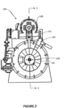
Figure 2 is a front elevation view of the burner assembly ofFigure 1 ; -
Figure 3 is a section view of the burner assembly ofFigure 2 , taken along line "3-3"; -
Figures 4 and 5 are perspective views depicting a nozzle end of the burner assembly ofFigure 1 with and without an airflow restrictor plate in accordance with an embodiment of the present invention mounted thereon, respectively; -
Figures 6A-6C illustrate three different burner assembly setups, each with a differently-sized airflow restrictor plate; -
Figures 7 and 8 are front elevation views depicting bolt-on airflow restrictor plates having center openings with radii R1 and R2, respectively, for use in a burner assembly according to an embodiment of the present invention; -
Figure 9 is a front elevation view depicting a semi-circular fan blocking plate, which may be used to form a circular fan blocking plate according to an embodiment of the present invention; -
Figure 10 is a perspective view depicting a internal section of a burner having a circular fan blocking plate mounted adjacent to a fan to restrict airflow according to an embodiment of the present invention; -
Figure 11 is a perspective view depicting the burner ofFigure 10 with the fan blocking plate removed; and -
Figure 12 is a chart illustrating airflow rates versus damper position for a burner assembly with and without a blocking plate. - This description of the preferred embodiments of the invention is intended to be read in connection with the accompanying drawings, which are to be considered part of the entire written description of this invention. The drawings are not necessarily to scale, and certain features of the invention may be shown exaggerated in scale or in somewhat schematic form in the interest of clarity and conciseness.
- Referring now to
Figures 1 - 3 , there is providedburner assembly 100 according to an embodiment of the present disclosure. Preferredburner assembly 100 includeshousing 102 having air inlet andnozzle end 104 having opening 106 that functions as an air outlet. The preferredburner assembly 100 also includes a motor such asvariable speed motor 108 for driving inlinecentrifugal fan 110 located nearfan end 112 ofhousing 102. Radial damper 132 is located at outlet side offan 110. Preferredlongitudinal axis 114 generally extends fromfan end 112 towardsnozzle end 104.Preferred housing 102 extends generally alonglongitudinal axis 114 and includes firsttubular housing portion 116 that is locatednearest fan 110 and that is removably mounted to secondtubular housing portion 118, which is located further downstream fromfan 110 than the first housing portion.Gaseous fuel line 120, which includes a gas injection nozzle (not shown), andigniter line 122 each extend along an outer surface of thehousing 102. Similarly, liquidfuel guide tube 124 and compressedair tube 126 extend throughhousing 102 inside ofcenter tube 128 tonozzle end 104 and atomizingnozzle 130. - When the
burner assembly 100 is in operation, thefan 110 is configured to create an airflow within thehousing 102, which airflow is modulated by thedamper 132. Thedamper 132 includes multiple vanes that can be moved between an open position, where airflow from thefan 110 through thehousing 102 is maximized, and a closed position, where airflow from the fan can be minimized or eliminated entirely. Thedamper 132 also has a number of intermediate positions between the open and closed positions that permit varying amounts of airflow through thehousing 102. Typically, the damper is set by selecting one of the several discrete set points that range from fully open and fully closed. For example, a typical damper might have 10 total positions that range from "0" to "9," where position "0" is fully or mostly closed and produces the least amount of airflow and position "9" is fully open and produces the greatest airflow. The airflow created by thefan 110 is carried through the first andsecond housing portions opening 106 at thenozzle end 104, where it is mixed with gaseous fuel and/or liquid fuel. Gaseous fuel is conveyed to thenozzle end 104 viagaseous fuel line 120. Liquid fuel and compressed air are conveyed to thenozzle end 104 inside of thecenter tube 128 by the liquidfuel guide tube 124 andcompressed air tube 126, respectively, where the liquid fuel is atomized by the atomizingnozzle 130. The air and fuel combination is ignited at thenozzle end 104 to create a flame. - Burners, such as
burner assembly 100, are often used as part of a large industrial or commercial dryer that is used to dry and process materials, such as aggregate material used in road construction. These dryers typically include large rotary drums that are placed around and extend outwards from thenozzle end 104 of theburner assembly 100. Preferably, the flame produced by theburner assembly 100 extends out through thenozzle end 104 viaopening 106 and into the drum to heat and dry the material that is being turned within the drum. Changes to the industrial or commercial processes that require the use of burners typically result in increased heating needs and, therefore, the replacement of a smaller burner with a larger one. For that reason, when initially sizing a burner for a particular application, it would be advantageous to size the burner to provide a heat output that is greater than the heat output that will initially be required by that application. This would allow for the heat output to be increased as the heating needs increased without requiring the burner to be replaced. However, oversizing a burner in this manner can create issues that must be corrected. - First, sizing a burner with the capacity to provide the large amount of fast-moving airflow required to produce high heat output makes adjusting the burner at low airflows more difficult. In particular, if the damper is sized for high amounts of airflow, the damper position required to achieve low airflows is achieved very quickly (e.g., at damper positions "4" or "5"), which limits the adjustability of the burner at low airflow rates. Another issue that may be caused by oversizing a burner is that the flame produced may damage portions of the dryer shell or other surrounding equipment and the temperature of the process and material being heated may be too high. For that reason, the
burner assembly 100 of the present invention provides means for increasing and decreasing the heat output of a burner that is also easily adjusted at different airflows. - With reference to
Figures 4-8 , the burner assembly of the present invention is provided with an airflowrestrictor plate 134 that may be used to selectively restrict airflow through the housing in order to vary the heat output of the burner assembly at the nozzle end. Therestrictor plate 134 is placed inside of the housing to restrict a portion of the airflow, as shown inFigure 4 , and to reduce the airflow velocity at the nozzle end of the burner assembly. When more airflow is needed to produce a greater heat output, a less restrictive airflowrestrictor plate 134 can be placed into the housing. Eventually, to have maximum airflow and heat output, therestrictor plate 134 can be removed entirely from the burner assembly, as shown inFigure 5 . Thus, an advantage of therestrictor plate 134 of the present design is that heat output can be modified very easily by exchanging a minimal number of components. - In preferred embodiments, the
restrictor plate 134 is mounted within thehousing 102 between thefirst housing portion 116 and thesecond housing portion 118. Therestrictor plate 134 is provided with an opening 136 through which airflow must pass in order to pass from thefirst housing portion 116 to thesecond housing portion 118 and to exit the housing. Preferably, the perimeter edge of the opening 136 in therestrictor plate 134 is smaller than the inside of thehousing 102, including thefirst housing portion 116 and thesecond housing portion 118, in order to restrict the air flowing through it. Therefore, preferredrestrictor plate 134 redirects (and slows) at least a portion of the airflow away from an inner wall surface of thefirst housing portion 116, through the opening 136, and into thesecond housing portion 118. - In certain preferred embodiments, the
burner assembly 100 includes two or moreairflow restrictor plates 134 that are interchangeable with one another. InFigures 6A - 6C , the nozzle end of a burner assembly having threerestrictor plates 134A-C of varying sizes is shown. - The
restrictor plate 134A shown inFigure 6A has anopening 136A with a radius R1 and is the most restrictive of the three (e.g., 25 MMBTU/hr plate) (e.g., 7.3 MW plate). Airflow passes byrestrictor plate 134A through the ring-shapedopening 136A that is formed between the restrictor plate and thecenter tube 128A. A less restrictiverestrictor plate 134B having anopening 136B with a radius R2 is shown inFigure 6B (e.g., 35 MMBTU/hr plate) (e.g., 10.2 MW plate). Lastly, the least restrictiverestrictor plate 134C having anopening 136C with a radius R3 is shown inFigure 6C (e.g., 50 MMBTU/hr plate) (e.g., 14.6 MW plate). Each of therestrictor plates 134A-C can be removed and exchanged as the heat output needs of the burner change. Alternatively, in other embodiments, the size of the opening in the airflow restrictor plate may be selectively adjusted to provide an opening having two or more different cross-sectional areas. For example, instead of using multipledifferent restrictor plates 134A-C with a fixed opening, a single restrictor plate having a re-sizeable opening (e.g., a mechanical iris) could be used. -
Figures 7 and 8 illustrate tworestrictor plates Figures 4 and 5 . Each of therestrictor plates flange 138 that surrounds theopening fastener openings 140. Additionally, one ormore cutouts 142 may be provided to receive thegaseous fuel line 120 andigniter line 122. To removably secure therestrictor plates burner assembly 100, the restrictor plate is placed against an end of thefirst housing portion 116 andopenings 140 in the restrictor plate are aligned with corresponding openings formed in a corresponding flange of the first housing portion. Next, thesecond housing portion 118 is placed against therestrictor plate first housing portion 116 and the second housing portion. Openings formed in a corresponding flange of thesecond housing portion 118 are aligned with the previously-aligned openings in therestrictor plate first housing portion 116. Fasteners are then passed throughfirst housing portion 116,restrictor plate second housing portion 118 and are fixed in place with threaded nuts. Lastly, thegaseous fuel line 120 andigniter line 122 are placed into thecutouts 142 and their ends are fitted into thesecond housing portion 118. - In preferred embodiments, in order to minimize equipment changes as process needs change, a damper having a high airflow capability may be initially selected for the burner assembly. The airflow may initially be adjusted downwards with the damper in order to limit the heat output to the then-required amount of heat. As heating needs increase, the damper may be opened to allow for greater airflow and to increase heat output. However, using a damper that is sized to provide high amounts of airflow in a low airflow situation causes the airflow required for that application to be achieved very quickly. For example, the needed airflow might be reached by position "5" of the damper, which leaves four additional positions (i.e., positions "6" through "9") that are not used. This limits the user's ability to make downward adjustments to the damper to reduce or moderate the airflow.
- Accordingly, with reference to
Figures 9-11 , preferred embodiments of the burner assembly of the present invention also include removablefan blocking plate 144 that is mounted adjacent the outlet side (downstream) from thedamper 132. Thefan blocking plate 144 is formed by twosemi-circular halves 146. Eachhalf 146 offan blocking plate 144 hasflat side 148 that includessemi-circular cutout 150. Whenburner assembly 100 is in low airflow mode, one ofhalves 146 is placedadjacent damper 132 and the cutout is positioned on one side ofcenter tube 128. Next,second half 146 is placedadjacent damper 132 such thatflat sides 148 are aligned andcutouts 150 encircle center tube 128 (Figure 10 ).Fan blocking plate 144 blocks a portion ofdamper 132 and reduces the velocity of airflow passing through the damper and housing. Reducing the velocity of the airflow when low airflow is required improves the ability ofburner assembly 100 to achieve the desired flow and heat output and increases the adjustability between its maximum and minimum airflow rates. Once airflow needs are increased,fan blocking plate 144 could be removed in order to increase velocity of the airflow and provide a higher heat output (Figure 11 ). - Typically, when comparing airflow to damper position, louvered dampers exhibit an airflow characteristic that is similar to a "quick open" valve, and airflow rate initially increases very rapidly as the damper is opened and then increases more slowly as the damper continues to be opened. This characteristic shape is illustrated, for example, in the upper curve in
Figure 12 (with data points denoted by diamond-shaped icons), which illustrates the air flowrates for a burner assembly that does not have a fan blocking plate at damper positions "0" thru "9." However, burners withfan blocking plate 144 exhibit an airflow characteristic that is much flatter and linear. This characteristic shape is illustrated, for example, in the lower curve (with data points denoted by triangle-shaped icons), which illustrates the air flowrates for an identical burner assembly having afan blocking plate 144 at the same damper positions as above. In both cases, the flowrate ranges from about 100,000 standard cubic feet per hour (SCFH) to about 400,000 SCFH (about 2832 to 11327 SCMH). When the burner assembly has no fan blocking plate, it achieves approximately 91% of its maximum flowrate range when the damper is at position "5." This provides only 5 damper positions for adjusting the flowrate downwards. On the other hand, when the burner assembly is equipped with a fan blocking plate, the flowrate curve is much flatter and the burner reaches approximately the same percentage of the maximum flowrate range (~93%) when the damper is at position "7." This provides a total of 7 damper positions for adjusting the flowrate downwards. Thus, a burner assembly equipped with a fan blocking plate according to the current invention has a greater amount of adjustability at low and mid-range airflow rates than an equivalent burner assembly that does not have a fan blocking plate. This adjustability enables a user to more easily obtain the desired airflow and to more precisely control the air-to-fuel ratio than in conventional burner systems. - Although this description contains many specifics, these should not be construed as limiting the scope of the invention but as merely providing illustrations of some of the presently preferred embodiments thereof, as well as the best mode contemplated by the inventor of carrying out the invention. The invention, as described and claimed herein, is susceptible to various modifications and adaptations as would be appreciated by those having ordinary skill in the art to which the invention relates.
Claims (12)
- A burner assembly (100) comprising:a housing (102) having an air inlet and an air outlet and configured to guide an airflow from the air inlet and out of the housing via the air outlet; an airflow restrictor plate (134, 234) for selectively restricting an amount of airflow passing out of the housing in order to adjust a heat output of the burner assembly, the airflow restrictor plate having a single opening (136) through which the airflow must pass in order to exit the housing via the air outlet;an inline centrifugal fan for generating the airflow;a motor (108) for powering the fan (110); anda damper (132) for modulating the airflow having an inlet side that is disposed at an outlet of the fan (110) that the airflow flows into and an outlet side that the airflow exits out of.
- The burner assembly (100) of claim 1 wherein the opening of the airflow restrictor plate (134) is substantially centered within the housing when the airflow restrictor is mounted to the housing and wherein a portion of the airflow is redirected by the airflow restrictor away from an inner wall surface of the housing and towards a center of the housing and then through the opening in the airflow restrictor plate (134) before exiting via the air outlet.
- The burner assembly (100) of claim 1 wherein the housing comprises:a first tubular housing portion; anda second tubular housing portion,wherein the airflow restrictor plate (134) is removably mounted between the first and second tubular housing portions, andwherein the airflow flows from the first tubular housing portion into the second tubular housing portion via the opening in the airflow restrictor.
- The burner assembly (100) of claim 3 wherein the first tubular housing portion has a first inner wall surface with a first diameter, the second tubular housing portion has a second inner wall surface with a second diameter, and the opening of airflow restrictor has a third diameter that is smaller than the first diameter and second diameter.
- The burner assembly (100) of claim 3 comprising two or more interchangeable airflow restrictor plates that each have a single opening with a different cross-sectional area such that the airflow through the housing may be varied by replacing one of the two or more airflow restrictor plates with another one of the two or more airflow restrictor plates.
- The burner assembly (100) of claim 1 comprising two or more interchangeable airflow restrictor plates that each have a single opening with a different cross-sectional area and that provide different degrees of restriction to the airflow based on the cross-sectional area of the opening.
- The burner assembly (100) of claim 1 further comprising:a fuel supply line extending along an outer surface of the housing and configured to provide fuel proximate the air outlet; anda cutout formed in the airflow restrictor plate (134) configured to receive the fuel supply line.
- The burner assembly (100) of claim 1 further comprising a fan blocking plate (144) removably located adjacent the outlet side of the damper and configured to block a portion of the airflow exiting the damper.
- The burner assembly (100) of claim 8 wherein the fan blocking plate (144) is circular in shape and has a center that is located concentric with a center of rotation of the fan.
- The burner assembly (100) of claim 8 wherein the fan blocking plate (144) is formed by two semi-circular halves that each have a flat side such that, when the flat sides are placed adjacent one another, a fan blocking plate (144) that is circular in shape is formed and a center of the circular fan blocking plate (144) is located concentric with a center of rotation of the fan (110).
- A method for adjusting the heat output of a fuel burner assembly (100), which fuel burner assembly (100) has a housing (102)with an air inlet provided in a first tubular housing portion, an air outlet provided in a second tubular housing portion, wherein an airflow is guided by the housing from the air inlet, through the first housing portion and second housing portion, and out of the housing via the air outlet, wherein the fuel burner assembly further comprises:a first airflow restrictor plate (134, 234) for restricting an amount of airflow passing out of the housing in order to reduce a heat output of the burner assembly (100), the airflow restrictor plate (134, 234) having a single opening through which airflow must pass in order to exit the housing via the air outlet;an inline centrifugal fan (110) for generating the airflow;a motor (108) for powering the fan (110); anda damper (132) for modulating the airflow having an inlet side that is disposed at an outlet of the fan that the airflow flows into and an outlet side that the airflow exits out of;the method comprising the steps of:providing said fuel burner assembly (100); andremovably locating the first airflow restrictor plate (134, 234) between the first and second tubular housing portions of the housing such that the airflow passes from the first housing portion to the second housing portion via the opening and, as a result of passing through the opening, the airflow experiences a first degree of restriction which results in a first heat output from the fuel burner assembly.
- The method of claim 11 further comprising the steps of:removing the first airflow restrictor plate (134) from between the first and second tubular housing portions; andremovably locating a second airflow restrictor plate (134) having an opening with a second cross-sectional area between the first and second tubular housing portions of the housing such that the airflow passes from the first housing portion to the second housing portion via the opening and, as a result of passing through the opening, the airflow experiences a second degree of restriction which results in a second heat output from the fuel burner assembly (100).
Applications Claiming Priority (2)
| Application Number | Priority Date | Filing Date | Title |
|---|---|---|---|
| US201962877562P | 2019-07-23 | 2019-07-23 | |
| PCT/US2019/052903 WO2021015805A1 (en) | 2019-07-23 | 2019-09-25 | Modular fuel burner assembly |
Publications (3)
| Publication Number | Publication Date |
|---|---|
| EP4004441A1 EP4004441A1 (en) | 2022-06-01 |
| EP4004441A4 EP4004441A4 (en) | 2023-12-13 |
| EP4004441B1 true EP4004441B1 (en) | 2025-04-02 |
Family
ID=74190164
Family Applications (1)
| Application Number | Title | Priority Date | Filing Date |
|---|---|---|---|
| EP19939026.1A Active EP4004441B1 (en) | 2019-07-23 | 2019-09-25 | Modular fuel burner assembly |
Country Status (8)
| Country | Link |
|---|---|
| US (1) | US11248788B2 (en) |
| EP (1) | EP4004441B1 (en) |
| AU (1) | AU2019458403B2 (en) |
| CA (1) | CA3148399C (en) |
| CO (1) | CO2022001854A2 (en) |
| FI (1) | FI4004441T3 (en) |
| MX (1) | MX2022000941A (en) |
| WO (1) | WO2021015805A1 (en) |
Family Cites Families (18)
| Publication number | Priority date | Publication date | Assignee | Title |
|---|---|---|---|---|
| US2007036A (en) * | 1935-07-02 | Orifice-provided element | ||
| US2443071A (en) * | 1944-11-28 | 1948-06-08 | Anemostat Corp | Air flow control valve |
| US3490858A (en) * | 1967-12-19 | 1970-01-20 | Stewart Warner Corp | Flame retention burner head assembly |
| US3637336A (en) * | 1969-12-29 | 1972-01-25 | North American Rockwell | Opposed vortex combustion chamber |
| US3820943A (en) * | 1972-05-26 | 1974-06-28 | Beckett R Corp | Power burner |
| US4096808A (en) * | 1976-11-11 | 1978-06-27 | Trickel Lorn L | Method and apparatus for burning air-suspended particulate fuel |
| US4383820A (en) | 1980-10-10 | 1983-05-17 | Technology Application Services Corporation | Fuel gas burner and method of producing a short flame |
| US4480988A (en) * | 1982-05-17 | 1984-11-06 | Osaka Gas Company, Limited | Surface combustion type burner with air supply entirely as primary air |
| US4422339A (en) * | 1982-10-25 | 1983-12-27 | Mcjunkin Corporation | Orifice fitting for a gas pressure differential-measuring system |
| US5839891A (en) * | 1997-01-13 | 1998-11-24 | Beckett Gas, Inc. | Power gas burner |
| DE19943612B4 (en) * | 1999-09-11 | 2004-07-15 | Robert Bosch Gmbh | Method for operating a gas burner with modulating burner output |
| US6857868B1 (en) * | 2003-08-20 | 2005-02-22 | Midco International, Inc. | Burner with a modular flame retention plate system |
| US20070224556A1 (en) * | 2006-03-10 | 2007-09-27 | Springstead Michael L | Diffuser plate for boiler burner feed assembly |
| US7497772B2 (en) * | 2006-07-20 | 2009-03-03 | The Boeing Company | Quick change restrictor plate |
| US7874835B2 (en) | 2008-03-27 | 2011-01-25 | Schwank Ltd. | Radiant tube heater and burner assembly for use therein |
| US9080773B2 (en) * | 2008-03-27 | 2015-07-14 | Schwank Ltd. | Pitot tube pressure sensor for radiant tube heater |
| US20150300640A1 (en) * | 2014-04-22 | 2015-10-22 | The Marley-Wylain Company | Minimum input air providing device and method |
| US11215380B2 (en) * | 2017-04-24 | 2022-01-04 | Regal Beloit America, Inc. | Combustion air blower with embossed housing |
-
2019
- 2019-09-25 AU AU2019458403A patent/AU2019458403B2/en active Active
- 2019-09-25 US US16/582,504 patent/US11248788B2/en active Active
- 2019-09-25 FI FIEP19939026.1T patent/FI4004441T3/en active
- 2019-09-25 CA CA3148399A patent/CA3148399C/en active Active
- 2019-09-25 WO PCT/US2019/052903 patent/WO2021015805A1/en not_active Ceased
- 2019-09-25 MX MX2022000941A patent/MX2022000941A/en unknown
- 2019-09-25 EP EP19939026.1A patent/EP4004441B1/en active Active
-
2022
- 2022-02-22 CO CONC2022/0001854A patent/CO2022001854A2/en unknown
Also Published As
| Publication number | Publication date |
|---|---|
| CA3148399C (en) | 2023-01-03 |
| AU2019458403B2 (en) | 2022-06-30 |
| MX2022000941A (en) | 2022-10-26 |
| US20210025587A1 (en) | 2021-01-28 |
| US11248788B2 (en) | 2022-02-15 |
| BR112022001204A2 (en) | 2022-05-10 |
| CA3148399A1 (en) | 2021-01-28 |
| AU2019458403A1 (en) | 2022-03-03 |
| FI4004441T3 (en) | 2025-05-21 |
| EP4004441A4 (en) | 2023-12-13 |
| EP4004441A1 (en) | 2022-06-01 |
| WO2021015805A1 (en) | 2021-01-28 |
| CO2022001854A2 (en) | 2022-03-29 |
Similar Documents
| Publication | Publication Date | Title |
|---|---|---|
| CA2982502C (en) | Burner with flow distribution member | |
| US3540484A (en) | Constant volume regulators and air distribution apparatus embodying same | |
| JP4624989B2 (en) | Balanced damper | |
| ITPD20090215A1 (en) | AIR-GAS MIXER DEVICE, PARTICULARLY FOR PRE-MIXING BURNER APPLIANCES. | |
| CA2657147A1 (en) | Radiant tube heater and burner assembly for use therein | |
| US2222822A (en) | Gas burner unit | |
| US6629523B2 (en) | Heated make-up air system | |
| US20220136269A1 (en) | Swimming Pool/Spa Gas Heater Inlet Mixer System And Associated Methods | |
| WO2018165660A1 (en) | Adjustable restrictor for burner | |
| CA3148399C (en) | Modular fuel burner assembly | |
| US4600377A (en) | Refractoriless liquid fuel burner | |
| KR20150052103A (en) | Electric variable-air-volume diffuser | |
| RU2785028C1 (en) | Modular fuel burner assembly | |
| CA2221210A1 (en) | Air distribution arrangement for paint spray booth | |
| EP0945678B1 (en) | Low NOx burner for liquid and gaseous fuels | |
| BR112022001204B1 (en) | BURNER ASSEMBLY AND METHOD FOR ADJUSTING HEAT EMISSION OF A FUEL BURNER ASSEMBLY | |
| RU2617856C1 (en) | Temperature-stabilizing pressure regulator | |
| KR100521387B1 (en) | Compulsive air feeding type combustion apparatus | |
| CN105509058A (en) | high modulation range mixer and premix system comprising thereof | |
| US12435872B2 (en) | High efficiency low NOx burner | |
| EP0186268B1 (en) | Air distribution terminals and air treatment systems | |
| CN208012111U (en) | A kind of inlet duct and full premix combustion water heater | |
| SU1116282A1 (en) | Heat generator | |
| RU2681809C2 (en) | Industrial diffuser | |
| GB2253476A (en) | An adjustable burner air swirl generator |
Legal Events
| Date | Code | Title | Description |
|---|---|---|---|
| STAA | Information on the status of an ep patent application or granted ep patent |
Free format text: STATUS: THE INTERNATIONAL PUBLICATION HAS BEEN MADE |
|
| PUAI | Public reference made under article 153(3) epc to a published international application that has entered the european phase |
Free format text: ORIGINAL CODE: 0009012 |
|
| STAA | Information on the status of an ep patent application or granted ep patent |
Free format text: STATUS: REQUEST FOR EXAMINATION WAS MADE |
|
| 17P | Request for examination filed |
Effective date: 20220217 |
|
| AK | Designated contracting states |
Kind code of ref document: A1 Designated state(s): AL AT BE BG CH CY CZ DE DK EE ES FI FR GB GR HR HU IE IS IT LI LT LU LV MC MK MT NL NO PL PT RO RS SE SI SK SM TR |
|
| DAV | Request for validation of the european patent (deleted) | ||
| DAX | Request for extension of the european patent (deleted) | ||
| P01 | Opt-out of the competence of the unified patent court (upc) registered |
Effective date: 20230526 |
|
| A4 | Supplementary search report drawn up and despatched |
Effective date: 20231115 |
|
| RIC1 | Information provided on ipc code assigned before grant |
Ipc: F23D 14/70 20060101ALI20231109BHEP Ipc: F23D 14/36 20060101AFI20231109BHEP |
|
| GRAP | Despatch of communication of intention to grant a patent |
Free format text: ORIGINAL CODE: EPIDOSNIGR1 |
|
| STAA | Information on the status of an ep patent application or granted ep patent |
Free format text: STATUS: GRANT OF PATENT IS INTENDED |
|
| INTG | Intention to grant announced |
Effective date: 20240909 |
|
| GRAJ | Information related to disapproval of communication of intention to grant by the applicant or resumption of examination proceedings by the epo deleted |
Free format text: ORIGINAL CODE: EPIDOSDIGR1 |
|
| STAA | Information on the status of an ep patent application or granted ep patent |
Free format text: STATUS: REQUEST FOR EXAMINATION WAS MADE |
|
| GRAP | Despatch of communication of intention to grant a patent |
Free format text: ORIGINAL CODE: EPIDOSNIGR1 |
|
| STAA | Information on the status of an ep patent application or granted ep patent |
Free format text: STATUS: GRANT OF PATENT IS INTENDED |
|
| INTC | Intention to grant announced (deleted) | ||
| INTG | Intention to grant announced |
Effective date: 20250121 |
|
| GRAS | Grant fee paid |
Free format text: ORIGINAL CODE: EPIDOSNIGR3 |
|
| GRAA | (expected) grant |
Free format text: ORIGINAL CODE: 0009210 |
|
| STAA | Information on the status of an ep patent application or granted ep patent |
Free format text: STATUS: THE PATENT HAS BEEN GRANTED |
|
| AK | Designated contracting states |
Kind code of ref document: B1 Designated state(s): AL AT BE BG CH CY CZ DE DK EE ES FI FR GB GR HR HU IE IS IT LI LT LU LV MC MK MT NL NO PL PT RO RS SE SI SK SM TR |
|
| REG | Reference to a national code |
Ref country code: GB Ref legal event code: FG4D |
|
| REG | Reference to a national code |
Ref country code: CH Ref legal event code: EP |
|
| REG | Reference to a national code |
Ref country code: IE Ref legal event code: FG4D Ref country code: NL Ref legal event code: FP |
|
| REG | Reference to a national code |
Ref country code: DE Ref legal event code: R096 Ref document number: 602019068287 Country of ref document: DE |
|
| REG | Reference to a national code |
Ref country code: SE Ref legal event code: TRGR |
|
| REG | Reference to a national code |
Ref country code: FI Ref legal event code: FGE |
|
| REG | Reference to a national code |
Ref country code: AT Ref legal event code: MK05 Ref document number: 1781585 Country of ref document: AT Kind code of ref document: T Effective date: 20250402 |
|
| REG | Reference to a national code |
Ref country code: CH Ref legal event code: U11 Free format text: ST27 STATUS EVENT CODE: U-0-0-U10-U11 (AS PROVIDED BY THE NATIONAL OFFICE) Effective date: 20251001 |
|
| PG25 | Lapsed in a contracting state [announced via postgrant information from national office to epo] |
Ref country code: ES Free format text: LAPSE BECAUSE OF FAILURE TO SUBMIT A TRANSLATION OF THE DESCRIPTION OR TO PAY THE FEE WITHIN THE PRESCRIBED TIME-LIMIT Effective date: 20250402 Ref country code: PT Free format text: LAPSE BECAUSE OF FAILURE TO SUBMIT A TRANSLATION OF THE DESCRIPTION OR TO PAY THE FEE WITHIN THE PRESCRIBED TIME-LIMIT Effective date: 20250804 |
|
| PGFP | Annual fee paid to national office [announced via postgrant information from national office to epo] |
Ref country code: FI Payment date: 20250917 Year of fee payment: 7 |
|
| PGFP | Annual fee paid to national office [announced via postgrant information from national office to epo] |
Ref country code: DE Payment date: 20250924 Year of fee payment: 7 |
|
| REG | Reference to a national code |
Ref country code: LT Ref legal event code: MG9D |
|
| PG25 | Lapsed in a contracting state [announced via postgrant information from national office to epo] |
Ref country code: GR Free format text: LAPSE BECAUSE OF FAILURE TO SUBMIT A TRANSLATION OF THE DESCRIPTION OR TO PAY THE FEE WITHIN THE PRESCRIBED TIME-LIMIT Effective date: 20250703 |
|
| PG25 | Lapsed in a contracting state [announced via postgrant information from national office to epo] |
Ref country code: PL Free format text: LAPSE BECAUSE OF FAILURE TO SUBMIT A TRANSLATION OF THE DESCRIPTION OR TO PAY THE FEE WITHIN THE PRESCRIBED TIME-LIMIT Effective date: 20250402 |
|
| PGFP | Annual fee paid to national office [announced via postgrant information from national office to epo] |
Ref country code: NL Payment date: 20250924 Year of fee payment: 7 |
|
| PG25 | Lapsed in a contracting state [announced via postgrant information from national office to epo] |
Ref country code: BG Free format text: LAPSE BECAUSE OF FAILURE TO SUBMIT A TRANSLATION OF THE DESCRIPTION OR TO PAY THE FEE WITHIN THE PRESCRIBED TIME-LIMIT Effective date: 20250402 |
|
| PGFP | Annual fee paid to national office [announced via postgrant information from national office to epo] |
Ref country code: GB Payment date: 20250911 Year of fee payment: 7 |
|
| PG25 | Lapsed in a contracting state [announced via postgrant information from national office to epo] |
Ref country code: HR Free format text: LAPSE BECAUSE OF FAILURE TO SUBMIT A TRANSLATION OF THE DESCRIPTION OR TO PAY THE FEE WITHIN THE PRESCRIBED TIME-LIMIT Effective date: 20250402 |
|
| PG25 | Lapsed in a contracting state [announced via postgrant information from national office to epo] |
Ref country code: AT Free format text: LAPSE BECAUSE OF FAILURE TO SUBMIT A TRANSLATION OF THE DESCRIPTION OR TO PAY THE FEE WITHIN THE PRESCRIBED TIME-LIMIT Effective date: 20250402 |
|
| PGFP | Annual fee paid to national office [announced via postgrant information from national office to epo] |
Ref country code: FR Payment date: 20250916 Year of fee payment: 7 |
|
| PGFP | Annual fee paid to national office [announced via postgrant information from national office to epo] |
Ref country code: SE Payment date: 20250914 Year of fee payment: 7 |
|
| PG25 | Lapsed in a contracting state [announced via postgrant information from national office to epo] |
Ref country code: RS Free format text: LAPSE BECAUSE OF FAILURE TO SUBMIT A TRANSLATION OF THE DESCRIPTION OR TO PAY THE FEE WITHIN THE PRESCRIBED TIME-LIMIT Effective date: 20250702 |
|
| PGFP | Annual fee paid to national office [announced via postgrant information from national office to epo] |
Ref country code: IE Payment date: 20250917 Year of fee payment: 7 |
|
| PG25 | Lapsed in a contracting state [announced via postgrant information from national office to epo] |
Ref country code: IS Free format text: LAPSE BECAUSE OF FAILURE TO SUBMIT A TRANSLATION OF THE DESCRIPTION OR TO PAY THE FEE WITHIN THE PRESCRIBED TIME-LIMIT Effective date: 20250802 |
|
| PG25 | Lapsed in a contracting state [announced via postgrant information from national office to epo] |
Ref country code: LV Free format text: LAPSE BECAUSE OF FAILURE TO SUBMIT A TRANSLATION OF THE DESCRIPTION OR TO PAY THE FEE WITHIN THE PRESCRIBED TIME-LIMIT Effective date: 20250402 |
|
| REG | Reference to a national code |
Ref country code: DE Ref legal event code: R097 Ref document number: 602019068287 Country of ref document: DE |
|
| PGFP | Annual fee paid to national office [announced via postgrant information from national office to epo] |
Ref country code: NO Payment date: 20251001 Year of fee payment: 7 |
|
| PG25 | Lapsed in a contracting state [announced via postgrant information from national office to epo] |
Ref country code: DK Free format text: LAPSE BECAUSE OF FAILURE TO SUBMIT A TRANSLATION OF THE DESCRIPTION OR TO PAY THE FEE WITHIN THE PRESCRIBED TIME-LIMIT Effective date: 20250402 Ref country code: SM Free format text: LAPSE BECAUSE OF FAILURE TO SUBMIT A TRANSLATION OF THE DESCRIPTION OR TO PAY THE FEE WITHIN THE PRESCRIBED TIME-LIMIT Effective date: 20250402 |
|
| PGFP | Annual fee paid to national office [announced via postgrant information from national office to epo] |
Ref country code: CH Payment date: 20251001 Year of fee payment: 7 |
|
| PG25 | Lapsed in a contracting state [announced via postgrant information from national office to epo] |
Ref country code: CZ Free format text: LAPSE BECAUSE OF FAILURE TO SUBMIT A TRANSLATION OF THE DESCRIPTION OR TO PAY THE FEE WITHIN THE PRESCRIBED TIME-LIMIT Effective date: 20250402 |
|
| PG25 | Lapsed in a contracting state [announced via postgrant information from national office to epo] |
Ref country code: EE Free format text: LAPSE BECAUSE OF FAILURE TO SUBMIT A TRANSLATION OF THE DESCRIPTION OR TO PAY THE FEE WITHIN THE PRESCRIBED TIME-LIMIT Effective date: 20250402 |
|
| PG25 | Lapsed in a contracting state [announced via postgrant information from national office to epo] |
Ref country code: RO Free format text: LAPSE BECAUSE OF FAILURE TO SUBMIT A TRANSLATION OF THE DESCRIPTION OR TO PAY THE FEE WITHIN THE PRESCRIBED TIME-LIMIT Effective date: 20250402 Ref country code: SK Free format text: LAPSE BECAUSE OF FAILURE TO SUBMIT A TRANSLATION OF THE DESCRIPTION OR TO PAY THE FEE WITHIN THE PRESCRIBED TIME-LIMIT Effective date: 20250402 |
|
| PG25 | Lapsed in a contracting state [announced via postgrant information from national office to epo] |
Ref country code: IT Free format text: LAPSE BECAUSE OF FAILURE TO SUBMIT A TRANSLATION OF THE DESCRIPTION OR TO PAY THE FEE WITHIN THE PRESCRIBED TIME-LIMIT Effective date: 20250402 |
|
| PLBE | No opposition filed within time limit |
Free format text: ORIGINAL CODE: 0009261 |
|
| STAA | Information on the status of an ep patent application or granted ep patent |
Free format text: STATUS: NO OPPOSITION FILED WITHIN TIME LIMIT |
|
| REG | Reference to a national code |
Ref country code: CH Ref legal event code: L10 Free format text: ST27 STATUS EVENT CODE: U-0-0-L10-L00 (AS PROVIDED BY THE NATIONAL OFFICE) Effective date: 20260211 |
|
| 26N | No opposition filed |
Effective date: 20260105 |
|
| REG | Reference to a national code |
Ref country code: DE Ref legal event code: R082 Ref document number: 602019068287 Country of ref document: DE Representative=s name: DR. RIEBLING & PARTNER PATENTANWAELTE MBB, DE |