EP4004441B1 - Modulare kraftstoffbrenneranordnung - Google Patents
Modulare kraftstoffbrenneranordnung Download PDFInfo
- Publication number
- EP4004441B1 EP4004441B1 EP19939026.1A EP19939026A EP4004441B1 EP 4004441 B1 EP4004441 B1 EP 4004441B1 EP 19939026 A EP19939026 A EP 19939026A EP 4004441 B1 EP4004441 B1 EP 4004441B1
- Authority
- EP
- European Patent Office
- Prior art keywords
- airflow
- burner assembly
- housing
- fan
- opening
- Prior art date
- Legal status (The legal status is an assumption and is not a legal conclusion. Google has not performed a legal analysis and makes no representation as to the accuracy of the status listed.)
- Active
Links
Images



Classifications
-
- F—MECHANICAL ENGINEERING; LIGHTING; HEATING; WEAPONS; BLASTING
- F23—COMBUSTION APPARATUS; COMBUSTION PROCESSES
- F23D—BURNERS
- F23D14/00—Burners for combustion of a gas, e.g. of a gas stored under pressure as a liquid
- F23D14/46—Details
- F23D14/70—Baffles or like flow-disturbing devices
-
- F—MECHANICAL ENGINEERING; LIGHTING; HEATING; WEAPONS; BLASTING
- F23—COMBUSTION APPARATUS; COMBUSTION PROCESSES
- F23D—BURNERS
- F23D14/00—Burners for combustion of a gas, e.g. of a gas stored under pressure as a liquid
- F23D14/02—Premix gas burners, i.e. in which gaseous fuel is mixed with combustion air upstream of the combustion zone
-
- F—MECHANICAL ENGINEERING; LIGHTING; HEATING; WEAPONS; BLASTING
- F23—COMBUSTION APPARATUS; COMBUSTION PROCESSES
- F23D—BURNERS
- F23D14/00—Burners for combustion of a gas, e.g. of a gas stored under pressure as a liquid
- F23D14/20—Non-premix gas burners, i.e. in which gaseous fuel is mixed with combustion air on arrival at the combustion zone
- F23D14/22—Non-premix gas burners, i.e. in which gaseous fuel is mixed with combustion air on arrival at the combustion zone with separate air and gas feed ducts, e.g. with ducts running parallel or crossing each other
-
- F—MECHANICAL ENGINEERING; LIGHTING; HEATING; WEAPONS; BLASTING
- F23—COMBUSTION APPARATUS; COMBUSTION PROCESSES
- F23D—BURNERS
- F23D17/00—Burners for combustion simultaneously or alternately of gaseous or liquid or pulverulent fuel
- F23D17/002—Burners for combustion simultaneously or alternately of gaseous or liquid or pulverulent fuel gaseous or liquid fuel
Definitions
- the invention relates generally to burners. More particularly, the present invention relates to modular gas- and oil-fired burners having adjustable heat outputs.
- the burner assembly includes two or more interchangeable airflow restrictor plates.
- Each of the airflow restrictor plates has openings with different cross-sectional areas such that airflow through the housing may be varied by replacing one of the two or more airflow restrictor plates with another one of the two or more airflow restrictor plates.
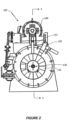
- burner assembly 100 includes housing 102 having air inlet and nozzle end 104 having opening 106 that functions as an air outlet.
- the preferred burner assembly 100 also includes a motor such as variable speed motor 108 for driving inline centrifugal fan 110 located near fan end 112 of housing 102.
- Radial damper 132 is located at outlet side of fan 110.
- Preferred longitudinal axis 114 generally extends from fan end 112 towards nozzle end 104.
- Preferred housing 102 extends generally along longitudinal axis 114 and includes first tubular housing portion 116 that is located nearest fan 110 and that is removably mounted to second tubular housing portion 118, which is located further downstream from fan 110 than the first housing portion.
- Gaseous fuel line 120 which includes a gas injection nozzle (not shown), and igniter line 122 each extend along an outer surface of the housing 102.
- liquid fuel guide tube 124 and compressed air tube 126 extend through housing 102 inside of center tube 128 to nozzle end 104 and atomizing nozzle 130.
- the fan 110 When the burner assembly 100 is in operation, the fan 110 is configured to create an airflow within the housing 102, which airflow is modulated by the damper 132.
- the damper 132 includes multiple vanes that can be moved between an open position, where airflow from the fan 110 through the housing 102 is maximized, and a closed position, where airflow from the fan can be minimized or eliminated entirely.
- the damper 132 also has a number of intermediate positions between the open and closed positions that permit varying amounts of airflow through the housing 102. Typically, the damper is set by selecting one of the several discrete set points that range from fully open and fully closed.
- a typical damper might have 10 total positions that range from “0” to “9,” where position "0” is fully or mostly closed and produces the least amount of airflow and position "9" is fully open and produces the greatest airflow.
- the airflow created by the fan 110 is carried through the first and second housing portions 116, 118 and exits through the opening 106 at the nozzle end 104, where it is mixed with gaseous fuel and/or liquid fuel.
- Gaseous fuel is conveyed to the nozzle end 104 via gaseous fuel line 120.
- Liquid fuel and compressed air are conveyed to the nozzle end 104 inside of the center tube 128 by the liquid fuel guide tube 124 and compressed air tube 126, respectively, where the liquid fuel is atomized by the atomizing nozzle 130.
- the air and fuel combination is ignited at the nozzle end 104 to create a flame.
- Burners such as burner assembly 100
- Burners are often used as part of a large industrial or commercial dryer that is used to dry and process materials, such as aggregate material used in road construction.
- These dryers typically include large rotary drums that are placed around and extend outwards from the nozzle end 104 of the burner assembly 100.
- the flame produced by the burner assembly 100 extends out through the nozzle end 104 via opening 106 and into the drum to heat and dry the material that is being turned within the drum.
- Changes to the industrial or commercial processes that require the use of burners typically result in increased heating needs and, therefore, the replacement of a smaller burner with a larger one.
- the burner assembly of the present invention is provided with an airflow restrictor plate 134 that may be used to selectively restrict airflow through the housing in order to vary the heat output of the burner assembly at the nozzle end.
- the restrictor plate 134 is placed inside of the housing to restrict a portion of the airflow, as shown in Figure 4 , and to reduce the airflow velocity at the nozzle end of the burner assembly.
- a less restrictive airflow restrictor plate 134 can be placed into the housing.
- the restrictor plate 134 can be removed entirely from the burner assembly, as shown in Figure 5 .
- an advantage of the restrictor plate 134 of the present design is that heat output can be modified very easily by exchanging a minimal number of components.
- the burner assembly 100 includes two or more airflow restrictor plates 134 that are interchangeable with one another.
- Figures 6A - 6C the nozzle end of a burner assembly having three restrictor plates 134A-C of varying sizes is shown.
Landscapes
- Engineering & Computer Science (AREA)
- Chemical & Material Sciences (AREA)
- Combustion & Propulsion (AREA)
- Mechanical Engineering (AREA)
- General Engineering & Computer Science (AREA)
- Gas Burners (AREA)
- Regulation And Control Of Combustion (AREA)
- Pressure-Spray And Ultrasonic-Wave- Spray Burners (AREA)
- Air Supply (AREA)
- Pre-Mixing And Non-Premixing Gas Burner (AREA)
Claims (12)
- Brenneranordnung (100), umfassend:ein Gehäuse (102), das einen Lufteinlass und einen Luftauslass hat und dazu konfiguriert ist, einen Luftstrom von dem Lufteinlass und über den Luftauslass aus dem Gehäuse heraus zu führen; eine Luftstromdrosselplatte (134, 234) zum selektiven Drosseln einer Menge eines Luftstroms, der aus dem Gehäuse ausströmt, um eine Heizleistung der Brenneranordnung einzustellen, wobei die Luftstromdrosselplatte eine einzige Öffnung (136) hat, durch welche der Luftstrom gelangen muss, um über den Luftauslass aus dem Gehäuse auszuströmen;ein Inline-Zentrifugalgebläse zum Erzeugen eines Luftstroms;einen Motor (108) zum Antreiben des Gebläses (110); undeinen Dämpfer (132) zum Modulieren des Luftstroms, der eine an einem Auslass des Gebläses (110) angeordnete Einlassseite, in die der Luftstrom einströmt, und eine Auslassseite hat, aus der der Luftstrom ausströmt.
- Brenneranordnung (100) gemäß Anspruch 1, wobei die Öffnung der Luftstromdrosselplatte (134) im Wesentlichen in dem Gehäuse zentriert ist, wenn die Luftstromdrosselplatte an dem Gehäuse montiert ist, und wobei ein Teil des Luftstroms von der Luftstromdrosselplatte von einer Innenwandfläche des Gehäuses weg und zu einer Mitte des Gehäuses und dann durch die Öffnung in der Luftstromdrosselplatte (134) umgeleitet wird, bevor er über den Luftauslass ausströmt.
- Brenneranordnung (100) gemäß Anspruch 1, wobei das Gehäuse umfasst:einen ersten rohrförmigen Gehäuseteil; undeinen zweiten rohrförmigen Gehäuseteil,wobei die Luftstromdrosselplatte (134) entfernbar zwischen dem ersten und dem zweiten rohrförmigen Gehäuseteil angebracht ist, undwobei der Luftstrom von dem ersten rohrförmigen Gehäuseteil über die Öffnung in der Luftstromdrossel in den zweiten rohrförmigen Gehäuseteil strömt.
- Brenneranordnung (100) gemäß Anspruch 3, wobei der erste rohrförmige Gehäuseteil eine erste Innenwandfläche mit einem ersten Durchmesser hat, der zweite rohrförmige Gehäuseteil eine zweite Innenwandfläche mit einem zweiten Durchmesser hat und die Öffnung der Luftstromdrossel einen dritten Durchmesser hat, der kleiner als der erste Durchmesser und der zweite Durchmesser ist.
- Brenneranordnung (100) gemäß Anspruch 3, umfassend zwei oder mehr austauschbare Luftstromdrosselplatten, die jeweils eine einzige Öffnung mit unterschiedlicher Querschnittsfläche haben, sodass der Luftstrom durch das Gehäuse dadurch variiert werden kann, dass eine der beiden oder mehreren Luftstromdrosselplatten durch eine andere der zwei oder mehr Luftstromdrosselplatten ersetzt werden kann.
- Brenneranordnung (100) gemäß Anspruch 1, umfassend zwei oder mehr austauschbare Luftstromdrosselplatten, die jeweils eine einzige Öffnung mit unterschiedlicher Querschnittsfläche haben und die unterschiedliche Grade der Drosselung des Luftstroms auf Basis der Querschnittsfläche der Öffnung bereitstellen.
- Brenneranordnung (100) gemäß Anspruch 1, ferner umfassend:eine Brennstoffzuführungsleitung, die sich entlang einer Außenoberfläche des Gehäuses erstreckt und dazu konfiguriert ist, Brennstoff in der Nähe des Luftauslasses bereitzustellen; undeinen Ausschnitt, der in der Luftstromdrosselplatte (134) ausgebildet ist, der dazu konfiguriert ist, die Brennstoffzuführungsleitung aufzunehmen.
- Brenneranordnung (100) gemäß Anspruch 1, ferner umfassend eine Gebläse-Blockierungsplatte (144), die entfernbar neben der Auslassseite des Dämpfers angeordnet ist und dazu konfiguriert ist, einen Teil des aus dem Dämpfer ausströmenden Luftstroms zu blockieren.
- Brenneranordnung (100) gemäß Anspruch 8, wobei die Gebläse-Blockierungsplatte (144) eine Kreisform hat und eine Mitte hat, die mit einem Drehpunkt des Gebläses konzentrisch angeordnet ist.
- Brenneranordnung (100) gemäß Anspruch 8, wobei die Gebläse-Blockierungsplatte (144) aus zwei halbkreisförmigen Hälften ausgebildet ist, die jeweils eine flache Seite haben, sodass, wenn die flachen Seiten aneinander anliegend angeordnet werden, eine Gebläse-Blockierungsplatte (144), die kreisförmig ist, ausgebildet wird und eine Mitte der kreisförmigen Gebläse-Blockierungsplatte (144) konzentrisch mit einem Drehpunkt des Gebläses (110) angeordnet ist.
- Verfahren zum Einstellen einer Heizleistung einer Brennstoff-Brenneranordnung (100), wobei die Brenneranordnung (100) ein Gehäuse (102) mit einem Lufteinlass hat, der in einem ersten rohrförmigen Gehäuseteil vorgesehen ist, einem Luftauslass, der in einem zweiten rohrförmigen Gehäuseteil vorgesehen ist, wobei ein Luftstrom durch das Gehäuse von dem Lufteinlass durch den ersten Gehäuseteil und den zweiten Gehäuseteil und über den Luftauslass aus dem Gehäuse heraus geführt wird, wobei die Brennstoff-Brenneranordnung ferner umfasst:eine erste Luftstromdrosselplatte (134, 234) zum Drosseln einer Menge eines aus dem Gehäuse ausströmenden Luftstroms, um eine Heizleistung der Brennstoff-Brenneranordnung (100) zu verringern, wobei die Luftstromdrosselplatte (134, 234) eine einzige Öffnung hat, durch welche der Luftstrom gelangen muss, um über den Luftauslass aus dem Gehäuse auszuströmen;ein Inline-Zentrifugalgebläse (110) zum Erzeugen eines Luftstroms;einen Motor (108) zum Antreiben des Gebläses (110); undeinen Dämpfer (132) zum Modulieren des Luftstroms, der eine Einlassseite, die an einem Auslass des Gebläses angeordnet ist, in die der Luftstrom einströmt, und eine Auslassseite hat, aus der der Luftstrom ausströmt;wobei das Verfahren die folgenden Schritte umfasst:Bereitstellen der Brennstoff-Brenneranordnung (100) undentfernbares Anordnen der ersten Luftstromdrosselplatte (134, 234) zwischen dem ersten und dem zweiten rohrförmigen Gehäuseteil des Gehäuses, sodass der Luftstrom von dem ersten Gehäuseteil über die Öffnung zum zweiten Gehäuseteil gelangt, und als Ergebnis eines Gelangens durch die Öffnung der Luftstrom einen ersten Grad einer Drosselung erfährt, der zu einer ersten Heizleistung aus der Brennstoff-Brenneranordnung führt.
- Verfahren gemäß Anspruch 11, ferner umfassend die folgenden Schritte:Entfernen der ersten Luftstromdrosselplatte (134) zwischen dem ersten und dem zweiten rohrförmigen Gehäuseteil; undentfernbares Anordnen einer zweiten Luftstromdrosselplatte (134), die eine Öffnung mit einer zweiten Querschnittsfläche hat, zwischen dem ersten und dem zweiten rohrförmigen Gehäuseteil des Gehäuses, sodass der Luftstrom von dem ersten Gehäuseteil über die Öffnung zum zweiten Gehäuseteil gelangt, und als Ergebnis eines Gelangens durch die Öffnung der Luftstrom einen zweiten Grad einer Drosselung erfährt, der zu einer zweiten Heizleistung aus der Brennstoff-Brenneranordnung (100) führt.
Applications Claiming Priority (2)
| Application Number | Priority Date | Filing Date | Title |
|---|---|---|---|
| US201962877562P | 2019-07-23 | 2019-07-23 | |
| PCT/US2019/052903 WO2021015805A1 (en) | 2019-07-23 | 2019-09-25 | Modular fuel burner assembly |
Publications (3)
| Publication Number | Publication Date |
|---|---|
| EP4004441A1 EP4004441A1 (de) | 2022-06-01 |
| EP4004441A4 EP4004441A4 (de) | 2023-12-13 |
| EP4004441B1 true EP4004441B1 (de) | 2025-04-02 |
Family
ID=74190164
Family Applications (1)
| Application Number | Title | Priority Date | Filing Date |
|---|---|---|---|
| EP19939026.1A Active EP4004441B1 (de) | 2019-07-23 | 2019-09-25 | Modulare kraftstoffbrenneranordnung |
Country Status (8)
| Country | Link |
|---|---|
| US (1) | US11248788B2 (de) |
| EP (1) | EP4004441B1 (de) |
| AU (1) | AU2019458403B2 (de) |
| CA (1) | CA3148399C (de) |
| CO (1) | CO2022001854A2 (de) |
| FI (1) | FI4004441T3 (de) |
| MX (1) | MX2022000941A (de) |
| WO (1) | WO2021015805A1 (de) |
Family Cites Families (18)
| Publication number | Priority date | Publication date | Assignee | Title |
|---|---|---|---|---|
| US2007036A (en) * | 1935-07-02 | Orifice-provided element | ||
| US2443071A (en) * | 1944-11-28 | 1948-06-08 | Anemostat Corp | Air flow control valve |
| US3490858A (en) * | 1967-12-19 | 1970-01-20 | Stewart Warner Corp | Flame retention burner head assembly |
| US3637336A (en) * | 1969-12-29 | 1972-01-25 | North American Rockwell | Opposed vortex combustion chamber |
| US3820943A (en) * | 1972-05-26 | 1974-06-28 | Beckett R Corp | Power burner |
| US4096808A (en) * | 1976-11-11 | 1978-06-27 | Trickel Lorn L | Method and apparatus for burning air-suspended particulate fuel |
| US4383820A (en) | 1980-10-10 | 1983-05-17 | Technology Application Services Corporation | Fuel gas burner and method of producing a short flame |
| US4480988A (en) * | 1982-05-17 | 1984-11-06 | Osaka Gas Company, Limited | Surface combustion type burner with air supply entirely as primary air |
| US4422339A (en) * | 1982-10-25 | 1983-12-27 | Mcjunkin Corporation | Orifice fitting for a gas pressure differential-measuring system |
| US5839891A (en) * | 1997-01-13 | 1998-11-24 | Beckett Gas, Inc. | Power gas burner |
| DE19943612B4 (de) * | 1999-09-11 | 2004-07-15 | Robert Bosch Gmbh | Verfahren zum Betreiben eines Gasbrenners mit modulierend geregelter Brennerleistung |
| US6857868B1 (en) * | 2003-08-20 | 2005-02-22 | Midco International, Inc. | Burner with a modular flame retention plate system |
| US20070224556A1 (en) * | 2006-03-10 | 2007-09-27 | Springstead Michael L | Diffuser plate for boiler burner feed assembly |
| US7497772B2 (en) * | 2006-07-20 | 2009-03-03 | The Boeing Company | Quick change restrictor plate |
| US7874835B2 (en) | 2008-03-27 | 2011-01-25 | Schwank Ltd. | Radiant tube heater and burner assembly for use therein |
| US9080773B2 (en) * | 2008-03-27 | 2015-07-14 | Schwank Ltd. | Pitot tube pressure sensor for radiant tube heater |
| US20150300640A1 (en) * | 2014-04-22 | 2015-10-22 | The Marley-Wylain Company | Minimum input air providing device and method |
| US11215380B2 (en) * | 2017-04-24 | 2022-01-04 | Regal Beloit America, Inc. | Combustion air blower with embossed housing |
-
2019
- 2019-09-25 AU AU2019458403A patent/AU2019458403B2/en active Active
- 2019-09-25 US US16/582,504 patent/US11248788B2/en active Active
- 2019-09-25 FI FIEP19939026.1T patent/FI4004441T3/fi active
- 2019-09-25 CA CA3148399A patent/CA3148399C/en active Active
- 2019-09-25 WO PCT/US2019/052903 patent/WO2021015805A1/en not_active Ceased
- 2019-09-25 MX MX2022000941A patent/MX2022000941A/es unknown
- 2019-09-25 EP EP19939026.1A patent/EP4004441B1/de active Active
-
2022
- 2022-02-22 CO CONC2022/0001854A patent/CO2022001854A2/es unknown
Also Published As
| Publication number | Publication date |
|---|---|
| CA3148399C (en) | 2023-01-03 |
| AU2019458403B2 (en) | 2022-06-30 |
| MX2022000941A (es) | 2022-10-26 |
| US20210025587A1 (en) | 2021-01-28 |
| US11248788B2 (en) | 2022-02-15 |
| BR112022001204A2 (pt) | 2022-05-10 |
| CA3148399A1 (en) | 2021-01-28 |
| AU2019458403A1 (en) | 2022-03-03 |
| FI4004441T3 (fi) | 2025-05-21 |
| EP4004441A4 (de) | 2023-12-13 |
| EP4004441A1 (de) | 2022-06-01 |
| WO2021015805A1 (en) | 2021-01-28 |
| CO2022001854A2 (es) | 2022-03-29 |
Similar Documents
| Publication | Publication Date | Title |
|---|---|---|
| CA2982502C (en) | Burner with flow distribution member | |
| US3540484A (en) | Constant volume regulators and air distribution apparatus embodying same | |
| JP4624989B2 (ja) | 平衡ダンパ | |
| ITPD20090215A1 (it) | Dispositivo miscelatore aria-gas, particolarmente per apparecchi bruciatori a pre-miscelazione. | |
| CA2657147A1 (en) | Radiant tube heater and burner assembly for use therein | |
| US2222822A (en) | Gas burner unit | |
| US6629523B2 (en) | Heated make-up air system | |
| US20220136269A1 (en) | Swimming Pool/Spa Gas Heater Inlet Mixer System And Associated Methods | |
| WO2018165660A1 (en) | Adjustable restrictor for burner | |
| CA3148399C (en) | Modular fuel burner assembly | |
| US4600377A (en) | Refractoriless liquid fuel burner | |
| KR20150052103A (ko) | 전기식 가변 풍량 디퓨저 | |
| RU2785028C1 (ru) | Узел модульной топливной горелки | |
| CA2221210A1 (en) | Air distribution arrangement for paint spray booth | |
| EP0945678B1 (de) | Brenner mit niedrigem NOx-Gehalt für flüssige und gasförmige Brennstoffe | |
| BR112022001204B1 (pt) | Conjunto de queimador e método para ajustar a emissão de calor de um conjunto de queimador de combustível | |
| RU2617856C1 (ru) | Термостабилизирующий регулятор давления | |
| KR100521387B1 (ko) | 강제급기식 복합연소장치 | |
| CN105509058A (zh) | 高调制范围的混合器以及包括它的预混系统 | |
| US12435872B2 (en) | High efficiency low NOx burner | |
| EP0186268B1 (de) | Luftverteil-Einrichtung und Luftbehandlungssystem | |
| CN208012111U (zh) | 一种进气装置及全预混燃烧热水器 | |
| SU1116282A1 (ru) | Теплогенератор | |
| RU2681809C2 (ru) | Диффузор индустриальный | |
| GB2253476A (en) | An adjustable burner air swirl generator |
Legal Events
| Date | Code | Title | Description |
|---|---|---|---|
| STAA | Information on the status of an ep patent application or granted ep patent |
Free format text: STATUS: THE INTERNATIONAL PUBLICATION HAS BEEN MADE |
|
| PUAI | Public reference made under article 153(3) epc to a published international application that has entered the european phase |
Free format text: ORIGINAL CODE: 0009012 |
|
| STAA | Information on the status of an ep patent application or granted ep patent |
Free format text: STATUS: REQUEST FOR EXAMINATION WAS MADE |
|
| 17P | Request for examination filed |
Effective date: 20220217 |
|
| AK | Designated contracting states |
Kind code of ref document: A1 Designated state(s): AL AT BE BG CH CY CZ DE DK EE ES FI FR GB GR HR HU IE IS IT LI LT LU LV MC MK MT NL NO PL PT RO RS SE SI SK SM TR |
|
| DAV | Request for validation of the european patent (deleted) | ||
| DAX | Request for extension of the european patent (deleted) | ||
| P01 | Opt-out of the competence of the unified patent court (upc) registered |
Effective date: 20230526 |
|
| A4 | Supplementary search report drawn up and despatched |
Effective date: 20231115 |
|
| RIC1 | Information provided on ipc code assigned before grant |
Ipc: F23D 14/70 20060101ALI20231109BHEP Ipc: F23D 14/36 20060101AFI20231109BHEP |
|
| GRAP | Despatch of communication of intention to grant a patent |
Free format text: ORIGINAL CODE: EPIDOSNIGR1 |
|
| STAA | Information on the status of an ep patent application or granted ep patent |
Free format text: STATUS: GRANT OF PATENT IS INTENDED |
|
| INTG | Intention to grant announced |
Effective date: 20240909 |
|
| GRAJ | Information related to disapproval of communication of intention to grant by the applicant or resumption of examination proceedings by the epo deleted |
Free format text: ORIGINAL CODE: EPIDOSDIGR1 |
|
| STAA | Information on the status of an ep patent application or granted ep patent |
Free format text: STATUS: REQUEST FOR EXAMINATION WAS MADE |
|
| GRAP | Despatch of communication of intention to grant a patent |
Free format text: ORIGINAL CODE: EPIDOSNIGR1 |
|
| STAA | Information on the status of an ep patent application or granted ep patent |
Free format text: STATUS: GRANT OF PATENT IS INTENDED |
|
| INTC | Intention to grant announced (deleted) | ||
| INTG | Intention to grant announced |
Effective date: 20250121 |
|
| GRAS | Grant fee paid |
Free format text: ORIGINAL CODE: EPIDOSNIGR3 |
|
| GRAA | (expected) grant |
Free format text: ORIGINAL CODE: 0009210 |
|
| STAA | Information on the status of an ep patent application or granted ep patent |
Free format text: STATUS: THE PATENT HAS BEEN GRANTED |
|
| AK | Designated contracting states |
Kind code of ref document: B1 Designated state(s): AL AT BE BG CH CY CZ DE DK EE ES FI FR GB GR HR HU IE IS IT LI LT LU LV MC MK MT NL NO PL PT RO RS SE SI SK SM TR |
|
| REG | Reference to a national code |
Ref country code: GB Ref legal event code: FG4D |
|
| REG | Reference to a national code |
Ref country code: CH Ref legal event code: EP |
|
| REG | Reference to a national code |
Ref country code: IE Ref legal event code: FG4D Ref country code: NL Ref legal event code: FP |
|
| REG | Reference to a national code |
Ref country code: DE Ref legal event code: R096 Ref document number: 602019068287 Country of ref document: DE |
|
| REG | Reference to a national code |
Ref country code: SE Ref legal event code: TRGR |
|
| REG | Reference to a national code |
Ref country code: FI Ref legal event code: FGE |
|
| REG | Reference to a national code |
Ref country code: AT Ref legal event code: MK05 Ref document number: 1781585 Country of ref document: AT Kind code of ref document: T Effective date: 20250402 |
|
| REG | Reference to a national code |
Ref country code: CH Ref legal event code: U11 Free format text: ST27 STATUS EVENT CODE: U-0-0-U10-U11 (AS PROVIDED BY THE NATIONAL OFFICE) Effective date: 20251001 |
|
| PG25 | Lapsed in a contracting state [announced via postgrant information from national office to epo] |
Ref country code: ES Free format text: LAPSE BECAUSE OF FAILURE TO SUBMIT A TRANSLATION OF THE DESCRIPTION OR TO PAY THE FEE WITHIN THE PRESCRIBED TIME-LIMIT Effective date: 20250402 Ref country code: PT Free format text: LAPSE BECAUSE OF FAILURE TO SUBMIT A TRANSLATION OF THE DESCRIPTION OR TO PAY THE FEE WITHIN THE PRESCRIBED TIME-LIMIT Effective date: 20250804 |
|
| PGFP | Annual fee paid to national office [announced via postgrant information from national office to epo] |
Ref country code: FI Payment date: 20250917 Year of fee payment: 7 |
|
| PGFP | Annual fee paid to national office [announced via postgrant information from national office to epo] |
Ref country code: DE Payment date: 20250924 Year of fee payment: 7 |
|
| REG | Reference to a national code |
Ref country code: LT Ref legal event code: MG9D |
|
| PG25 | Lapsed in a contracting state [announced via postgrant information from national office to epo] |
Ref country code: GR Free format text: LAPSE BECAUSE OF FAILURE TO SUBMIT A TRANSLATION OF THE DESCRIPTION OR TO PAY THE FEE WITHIN THE PRESCRIBED TIME-LIMIT Effective date: 20250703 |
|
| PG25 | Lapsed in a contracting state [announced via postgrant information from national office to epo] |
Ref country code: PL Free format text: LAPSE BECAUSE OF FAILURE TO SUBMIT A TRANSLATION OF THE DESCRIPTION OR TO PAY THE FEE WITHIN THE PRESCRIBED TIME-LIMIT Effective date: 20250402 |
|
| PGFP | Annual fee paid to national office [announced via postgrant information from national office to epo] |
Ref country code: NL Payment date: 20250924 Year of fee payment: 7 |
|
| PG25 | Lapsed in a contracting state [announced via postgrant information from national office to epo] |
Ref country code: BG Free format text: LAPSE BECAUSE OF FAILURE TO SUBMIT A TRANSLATION OF THE DESCRIPTION OR TO PAY THE FEE WITHIN THE PRESCRIBED TIME-LIMIT Effective date: 20250402 |
|
| PGFP | Annual fee paid to national office [announced via postgrant information from national office to epo] |
Ref country code: GB Payment date: 20250911 Year of fee payment: 7 |
|
| PG25 | Lapsed in a contracting state [announced via postgrant information from national office to epo] |
Ref country code: HR Free format text: LAPSE BECAUSE OF FAILURE TO SUBMIT A TRANSLATION OF THE DESCRIPTION OR TO PAY THE FEE WITHIN THE PRESCRIBED TIME-LIMIT Effective date: 20250402 |
|
| PG25 | Lapsed in a contracting state [announced via postgrant information from national office to epo] |
Ref country code: AT Free format text: LAPSE BECAUSE OF FAILURE TO SUBMIT A TRANSLATION OF THE DESCRIPTION OR TO PAY THE FEE WITHIN THE PRESCRIBED TIME-LIMIT Effective date: 20250402 |
|
| PGFP | Annual fee paid to national office [announced via postgrant information from national office to epo] |
Ref country code: FR Payment date: 20250916 Year of fee payment: 7 |
|
| PGFP | Annual fee paid to national office [announced via postgrant information from national office to epo] |
Ref country code: SE Payment date: 20250914 Year of fee payment: 7 |
|
| PG25 | Lapsed in a contracting state [announced via postgrant information from national office to epo] |
Ref country code: RS Free format text: LAPSE BECAUSE OF FAILURE TO SUBMIT A TRANSLATION OF THE DESCRIPTION OR TO PAY THE FEE WITHIN THE PRESCRIBED TIME-LIMIT Effective date: 20250702 |
|
| PGFP | Annual fee paid to national office [announced via postgrant information from national office to epo] |
Ref country code: IE Payment date: 20250917 Year of fee payment: 7 |
|
| PG25 | Lapsed in a contracting state [announced via postgrant information from national office to epo] |
Ref country code: IS Free format text: LAPSE BECAUSE OF FAILURE TO SUBMIT A TRANSLATION OF THE DESCRIPTION OR TO PAY THE FEE WITHIN THE PRESCRIBED TIME-LIMIT Effective date: 20250802 |
|
| PG25 | Lapsed in a contracting state [announced via postgrant information from national office to epo] |
Ref country code: LV Free format text: LAPSE BECAUSE OF FAILURE TO SUBMIT A TRANSLATION OF THE DESCRIPTION OR TO PAY THE FEE WITHIN THE PRESCRIBED TIME-LIMIT Effective date: 20250402 |
|
| REG | Reference to a national code |
Ref country code: DE Ref legal event code: R097 Ref document number: 602019068287 Country of ref document: DE |
|
| PGFP | Annual fee paid to national office [announced via postgrant information from national office to epo] |
Ref country code: NO Payment date: 20251001 Year of fee payment: 7 |
|
| PG25 | Lapsed in a contracting state [announced via postgrant information from national office to epo] |
Ref country code: DK Free format text: LAPSE BECAUSE OF FAILURE TO SUBMIT A TRANSLATION OF THE DESCRIPTION OR TO PAY THE FEE WITHIN THE PRESCRIBED TIME-LIMIT Effective date: 20250402 Ref country code: SM Free format text: LAPSE BECAUSE OF FAILURE TO SUBMIT A TRANSLATION OF THE DESCRIPTION OR TO PAY THE FEE WITHIN THE PRESCRIBED TIME-LIMIT Effective date: 20250402 |
|
| PGFP | Annual fee paid to national office [announced via postgrant information from national office to epo] |
Ref country code: CH Payment date: 20251001 Year of fee payment: 7 |
|
| PG25 | Lapsed in a contracting state [announced via postgrant information from national office to epo] |
Ref country code: CZ Free format text: LAPSE BECAUSE OF FAILURE TO SUBMIT A TRANSLATION OF THE DESCRIPTION OR TO PAY THE FEE WITHIN THE PRESCRIBED TIME-LIMIT Effective date: 20250402 |
|
| PG25 | Lapsed in a contracting state [announced via postgrant information from national office to epo] |
Ref country code: EE Free format text: LAPSE BECAUSE OF FAILURE TO SUBMIT A TRANSLATION OF THE DESCRIPTION OR TO PAY THE FEE WITHIN THE PRESCRIBED TIME-LIMIT Effective date: 20250402 |
|
| PG25 | Lapsed in a contracting state [announced via postgrant information from national office to epo] |
Ref country code: RO Free format text: LAPSE BECAUSE OF FAILURE TO SUBMIT A TRANSLATION OF THE DESCRIPTION OR TO PAY THE FEE WITHIN THE PRESCRIBED TIME-LIMIT Effective date: 20250402 Ref country code: SK Free format text: LAPSE BECAUSE OF FAILURE TO SUBMIT A TRANSLATION OF THE DESCRIPTION OR TO PAY THE FEE WITHIN THE PRESCRIBED TIME-LIMIT Effective date: 20250402 |
|
| PG25 | Lapsed in a contracting state [announced via postgrant information from national office to epo] |
Ref country code: IT Free format text: LAPSE BECAUSE OF FAILURE TO SUBMIT A TRANSLATION OF THE DESCRIPTION OR TO PAY THE FEE WITHIN THE PRESCRIBED TIME-LIMIT Effective date: 20250402 |
|
| PLBE | No opposition filed within time limit |
Free format text: ORIGINAL CODE: 0009261 |
|
| STAA | Information on the status of an ep patent application or granted ep patent |
Free format text: STATUS: NO OPPOSITION FILED WITHIN TIME LIMIT |
|
| REG | Reference to a national code |
Ref country code: CH Ref legal event code: L10 Free format text: ST27 STATUS EVENT CODE: U-0-0-L10-L00 (AS PROVIDED BY THE NATIONAL OFFICE) Effective date: 20260211 |
|
| 26N | No opposition filed |
Effective date: 20260105 |
|
| REG | Reference to a national code |
Ref country code: DE Ref legal event code: R082 Ref document number: 602019068287 Country of ref document: DE Representative=s name: DR. RIEBLING & PARTNER PATENTANWAELTE MBB, DE |