EP4003891B1 - Adjustable coil adapter mechanism - Google Patents
Adjustable coil adapter mechanism Download PDFInfo
- Publication number
- EP4003891B1 EP4003891B1 EP20843602.2A EP20843602A EP4003891B1 EP 4003891 B1 EP4003891 B1 EP 4003891B1 EP 20843602 A EP20843602 A EP 20843602A EP 4003891 B1 EP4003891 B1 EP 4003891B1
- Authority
- EP
- European Patent Office
- Prior art keywords
- pintle
- flanges
- pay
- finger
- core
- Prior art date
- Legal status (The legal status is an assumption and is not a legal conclusion. Google has not performed a legal analysis and makes no representation as to the accuracy of the status listed.)
- Active
Links
Images



Classifications
-
- B—PERFORMING OPERATIONS; TRANSPORTING
- B65—CONVEYING; PACKING; STORING; HANDLING THIN OR FILAMENTARY MATERIAL
- B65H—HANDLING THIN OR FILAMENTARY MATERIAL, e.g. SHEETS, WEBS, CABLES
- B65H49/00—Unwinding or paying-out filamentary material; Supporting, storing or transporting packages from which filamentary material is to be withdrawn or paid-out
- B65H49/36—Securing packages to supporting devices
-
- B—PERFORMING OPERATIONS; TRANSPORTING
- B65—CONVEYING; PACKING; STORING; HANDLING THIN OR FILAMENTARY MATERIAL
- B65H—HANDLING THIN OR FILAMENTARY MATERIAL, e.g. SHEETS, WEBS, CABLES
- B65H75/00—Storing webs, tapes, or filamentary material, e.g. on reels
- B65H75/02—Cores, formers, supports, or holders for coiled, wound, or folded material, e.g. reels, spindles, bobbins, cop tubes, cans, mandrels or chucks
- B65H75/18—Constructional details
- B65H75/24—Constructional details adjustable in configuration, e.g. expansible
- B65H75/242—Expansible spindles, mandrels or chucks, e.g. for securing or releasing cores, holders or packages
-
- B—PERFORMING OPERATIONS; TRANSPORTING
- B65—CONVEYING; PACKING; STORING; HANDLING THIN OR FILAMENTARY MATERIAL
- B65H—HANDLING THIN OR FILAMENTARY MATERIAL, e.g. SHEETS, WEBS, CABLES
- B65H75/00—Storing webs, tapes, or filamentary material, e.g. on reels
- B65H75/02—Cores, formers, supports, or holders for coiled, wound, or folded material, e.g. reels, spindles, bobbins, cop tubes, cans, mandrels or chucks
- B65H75/18—Constructional details
- B65H75/24—Constructional details adjustable in configuration, e.g. expansible
- B65H75/242—Expansible spindles, mandrels or chucks, e.g. for securing or releasing cores, holders or packages
- B65H75/2495—Expansible spindles, mandrels or chucks, e.g. for securing or releasing cores, holders or packages including plural segments or spokes which are individually adjustable
Definitions
- the present invention relates to an apparatus and or system used to coil and or uncoil lengths of elongate materials such as but not limited to hoses, cable, tubing, wiring and the like. More particularly, the present invention provides an improved adjustable coil adapter mechanism for but not limited to cardboard core coil packs.
- Spooling is typically a reference to taking the elongated material from a large spool and or reel to a smaller desired length for redistribution then wrapped around another spool and or reel for redistribution.
- Coiling is typically a reference to taking the elongated material from a large spool and or reel to a smaller desired length for redistribution and wrapping it freely into a coil with no spool and or reel.
- some elongated material may come from and or be wound on a spool with a cardboard core that is installed in a piece of equipment, such as but not limited to a pay-off machine, for unwinding and transferring onto another machine such as automatic cut and transfer coiling and or spooling machines.
- the inner diameters or ID's of the cardboard cores can vary slightly and need to be gripped firmly while the material is being transferred at a high rate of speed to another machine.
- Prior art methods for gripping the coil core include manually expanding an adapter inside the core and then installing lock bolts to squeeze the flanges axially against the core. These are labor intensive and can impact overall process time.
- CH618661A5 discloses a pay-out machine according to the preamble of claim 1 and describes a mandrel for tensioning a film roll, the film of which is wound onto a sleeve or without a sleeve to form a passage in the roll centre, the clamping jaws of the mandrel each being positively and displaceably mounted in a first guide groove arranged radially on the end face of a housing.
- JP2013155004A describes a support device to enable rotation of a long body that allows the displacement means to be separated and approached without relying on elastic force and facilitates the attaching/ detaching operation of the rotation support object inserted into or removed from the displacement means.
- US3840195A describes a core axle assembly which employs at least one radially shiftable gripper bar whose radial movement is effected by an inclined cam surface action in response to axial force directed against the gripper bar or bars.
- the present invention provides a new and improved apparatus.
- the general purpose of the present invention which will be described subsequently in greater detail, is to provide a new and improved uncoiling and or coiling head for use with elongated materials, which has all the advantages of the prior art devices and none and or fewer of the disadvantages.
- the present invention is an apparatus for a new and improved adjustable coil adapter mechanism for cardboard core coil packs that may include an adjustable, pintle style adapter with finite adjustment to a given range of core sizes.
- Adjustable, tapered finger plates ride on a sloped groove that positions them along the diameter of the cardboard core. These finger plates securely grip the ID of the core with only the axial motion of the activating cylinder.
- a sloped groove may provide macro adjustment to account for large differences in core ID's.
- an object of the present invention is to provide a new and improved adjustable coil adapter apparatus, which allows for adjustable, pintle style flange adapter that allows direct installation of the wire coil pack with cardboard core, engaging both the ID and axial ends of the core by the activating cylinder motion, reducing human interaction and both labor and process time.
- Another object of the present invention is to provide a new and improved adjustable coil adapter apparatus, which may provide macro adjustment to account for large differences in cardboard core ID's.
- Still another object of the present invention is to provide a new and improved adjustable coil adapter apparatus, that may provide a fixed taper at the top of the finger plates, provides an interference fit, similar to the expanding core, and ensures adequate gripping force over at least half the length of the core.
- Yet still another object of the present invention is to provide a new and improved adjustable coil adapter apparatus, that may provide adjustable, tapered finger plates that may ride on a sloped groove that position them along the diameter of the cardboard core. These finger plates may securely grip the ID of the core with only the axial motion of the activating cylinder.
- An even further object of the present invention is to provide a new and improved adjustable coil adapter apparatus, which is susceptible to a low cost of manufacture, which accordingly is then susceptible to low prices of sale to the consuming industry, thereby making such a system economically available to those in the industry.
- Still another object of the present invention is to provide a new and improved adjustable coil adapter apparatus, which provides all of the advantages of the prior art while simultaneously overcoming some of the disadvantages normally associated therewith.
- reference character 10 generally designates a new and improved adjustable coil adapter for cardboard core coil packs apparatus constructed in accordance with the present invention.
- Invention 10 is generally used with elongated materials needing to be made into smaller segments for distribution from a larger spool and or reel utilized on a pay-off machine.
- Elongated materials may be but are not limited to electrical cables, steel cables, wire cables, hoses and so forth placed on a cylinder 20 that may be made from but not limited to cardboard It is understood that cylinder may be made from other relatively soft construction material. It is contemplated that invention 10 may be utilized with prior art devices.
- reference numeral 10 may generally be utilized for the indication of the invention, portion of the invention, preferred embodiments of the invention and so on. It is also to be understood that invention 10 should not be considered limited to just an uncoiling and coiling from cardboard core coil packs and the terms should not be considered to limit the invention to such.
- Invention 10 may generally include head 30 that may be mounted to a pay-out machine 40.
- Head 30 may have a first side and or first end 50, a second side and or second end 60.
- Head 30 may have numerous pintle flanges 70, such as but not limited to six. It is understood that more or less are contemplated.
- Pintle flange 70 may have an angled and or sloped slot 80 for positioning finger wedges 90 with threaded receptor 100 for communication with threaded screw 110. Finger wedges 90 are threaded so they slide axially in and out with screw 110 and therefor the effective diameter 120 of the finger wedges 90 increases or decreases as each of the finger wedges 90 are adjusted together.
- Sloped slot 80 generally corresponds with finger wedge 90 bottom angle 130.
- Finger wedge 90 may include scribe lines 140 to help keep all finger wedge(s) 90 at the same height to ensure the coil pack stays concentric on head 30.
- Finger wedge 90 top 150 may be slightly tapered to grip the inner diameter of the core. Screw 110 may be selectively captive against retaining plate 160 with a lock nut 170.
- the current invention is a pay-out machine for unwrapping elongated materials from a cardboard coil package comprising: a head having a first side and a second side wherein said second side is attached to said pay-out machine, at least four pintle flanges attached to said first side of said head wherein said at least four pintle flanges have sloped slots, at least four finger wedges positioned respectively in said sloped slots of said at least four pintle flanges and wherein said at least four finger wedges respectively have at least four threaded receptors and wherein said at least four finger wedges respectively have at least four corresponding slopes to match said sloped slots of said at least four pintle flanges, at least four threaded screws axially connecting said at least four threaded receptors of said at least four finger wedges to said at least four pintle flanges; and wherein the at least four threaded screws' respective rotation are adapted to keep said cardboard coil package concentric while unwrapping elongated materials from said
Landscapes
- Storage Of Web-Like Or Filamentary Materials (AREA)
- Replacement Of Web Rolls (AREA)
Description
- In general, the present invention relates to an apparatus and or system used to coil and or uncoil lengths of elongate materials such as but not limited to hoses, cable, tubing, wiring and the like. More particularly, the present invention provides an improved adjustable coil adapter mechanism for but not limited to cardboard core coil packs.
- In general, lengths of material that are usually relatively long and flexible are wound on large reels and or spools by a manufacturer. It is known for redistribution to take these large reels and or spools of materials into smaller amounts for redistribution. The machines associated with such are often referred to as automatic cut and transfer coiling and or spooling machines. Spooling is typically a reference to taking the elongated material from a large spool and or reel to a smaller desired length for redistribution then wrapped around another spool and or reel for redistribution. Coiling is typically a reference to taking the elongated material from a large spool and or reel to a smaller desired length for redistribution and wrapping it freely into a coil with no spool and or reel.
- It is known that some elongated material may come from and or be wound on a spool with a cardboard core that is installed in a piece of equipment, such as but not limited to a pay-off machine, for unwinding and transferring onto another machine such as automatic cut and transfer coiling and or spooling machines. The inner diameters or ID's of the cardboard cores can vary slightly and need to be gripped firmly while the material is being transferred at a high rate of speed to another machine. Prior art methods for gripping the coil core include manually expanding an adapter inside the core and then installing lock bolts to squeeze the flanges axially against the core. These are labor intensive and can impact overall process time.
-
CH618661A5 -
JP2013155004A -
US3840195A describes a core axle assembly which employs at least one radially shiftable gripper bar whose radial movement is effected by an inclined cam surface action in response to axial force directed against the gripper bar or bars. - Thus, there is a need for a new and improved adjustable coil adapter mechanism for cardboard core coil packs. It is desirable to fill these needs with a reliable alternative that is affordable and functional. The above discussed limitations in the prior art is not exhaustive. The current invention provides an inexpensive, time saving, more reliable apparatus where the prior art fails.
- In view of the foregoing disadvantages inherent in the known types of uncoiling and or coiling now present in the prior art, the present invention provides a new and improved apparatus. As such, the general purpose of the present invention, which will be described subsequently in greater detail, is to provide a new and improved uncoiling and or coiling head for use with elongated materials, which has all the advantages of the prior art devices and none and or fewer of the disadvantages.
- It is, therefore, contemplated that the present invention is an apparatus for a new and improved adjustable coil adapter mechanism for cardboard core coil packs that may include an adjustable, pintle style adapter with finite adjustment to a given range of core sizes. Adjustable, tapered finger plates ride on a sloped groove that positions them along the diameter of the cardboard core. These finger plates securely grip the ID of the core with only the axial motion of the activating cylinder. A sloped groove may provide macro adjustment to account for large differences in core ID's.
- There has thus been outlined, rather broadly, the more important features of the invention in order that the detailed description thereof that follows may be better understood and in order that the present contribution to the art may be better appreciated. There are, of course, additional features of the invention that will be described hereinafter and which will form the subject matter of the claim appended hereto.
- In this respect, before explaining at least one embodiment of the invention in detail, it is to be understood that the invention is not limited in this application to the details of construction and to the arrangements of the components set forth in the following description or illustrated in the drawings. The invention is capable of other embodiments and of being practiced and carried out in various ways.
- Therefore, it is an object of the present invention to provide a new and improved adjustable coil adapter for cardboard core coil packs apparatus for use with elongated materials where it is desirable to prevent and or reduce time associated to adjust for variable inner diameters of the cardboard core.
- Furthermore, an object of the present invention is to provide a new and improved adjustable coil adapter apparatus, which allows for adjustable, pintle style flange adapter that allows direct installation of the wire coil pack with cardboard core, engaging both the ID and axial ends of the core by the activating cylinder motion, reducing human interaction and both labor and process time.
- Another object of the present invention is to provide a new and improved adjustable coil adapter apparatus, which may provide macro adjustment to account for large differences in cardboard core ID's.
- Still another object of the present invention is to provide a new and improved adjustable coil adapter apparatus, that may provide a fixed taper at the top of the finger plates, provides an interference fit, similar to the expanding core, and ensures adequate gripping force over at least half the length of the core.
- Yet still another object of the present invention is to provide a new and improved adjustable coil adapter apparatus, that may provide adjustable, tapered finger plates that may ride on a sloped groove that position them along the diameter of the cardboard core. These finger plates may securely grip the ID of the core with only the axial motion of the activating cylinder.
- It is a further object of the present invention to provide a new and improved adjustable coil adapter apparatus, which is of a durable and reliable construction and may be utilized in numerous types of coiling and or uncoiling applications.
- An even further object of the present invention is to provide a new and improved adjustable coil adapter apparatus, which is susceptible to a low cost of manufacture, which accordingly is then susceptible to low prices of sale to the consuming industry, thereby making such a system economically available to those in the industry.
- Still another object of the present invention is to provide a new and improved adjustable coil adapter apparatus, which provides all of the advantages of the prior art while simultaneously overcoming some of the disadvantages normally associated therewith.
- These, together with other objects of the invention, along with the various features of novelty, which characterize the invention, are pointed out with particularity in the claim annexed to and forming a part of this disclosure. For a better understanding of the invention, its operating advantages, and the specific objects attained by its uses, reference should be had to the accompanying drawings and descriptive matter in which there are illustrated preferred embodiments of the invention.
- The invention will be better understood and objects other than those set forth above will become apparent when consideration is given to the following detailed description thereof. Such description makes reference to the annexed pictorial illustrations, graphs, drawings, and appendices.
-
Figure 1 is a general perspective illustration of a preferred embodiment of the invention depicting a head and part of a pay-off machine. -
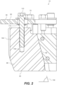
Figure 2 is a general partial cutaway of a preferred embodiment of the invention. -
Figure 3 is a general partial cutaway of a preferred embodiment of the invention. -
Figure 4 is a general perspective illustration of a preferred embodiment of the invention depicting a back view of the head. -
Figure 5 is a general perspective illustration of a preferred embodiment of the invention depicting a front view of the head. -
Figure 6 is a general top view of a head of a preferred embodiment of the invention. -
Figure 7 is a general back view of a head of a preferred embodiment of the invention. - Referring to the illustrations, drawings, and pictures, and to
Figure 1 in particular,reference character 10 generally designates a new and improved adjustable coil adapter for cardboard core coil packs apparatus constructed in accordance with the present invention.Invention 10 is generally used with elongated materials needing to be made into smaller segments for distribution from a larger spool and or reel utilized on a pay-off machine. Elongated materials may be but are not limited to electrical cables, steel cables, wire cables, hoses and so forth placed on acylinder 20 that may be made from but not limited to cardboard It is understood that cylinder may be made from other relatively soft construction material. It is contemplated thatinvention 10 may be utilized with prior art devices. For purposes of convenience, thereference numeral 10 may generally be utilized for the indication of the invention, portion of the invention, preferred embodiments of the invention and so on. It is also to be understood thatinvention 10 should not be considered limited to just an uncoiling and coiling from cardboard core coil packs and the terms should not be considered to limit the invention to such. -
Invention 10 may generally includehead 30 that may be mounted to a pay-outmachine 40.Head 30 may have a first side and orfirst end 50, a second side and orsecond end 60.Head 30 may havenumerous pintle flanges 70, such as but not limited to six. It is understood that more or less are contemplated.Pintle flange 70 may have an angled and or slopedslot 80 for positioningfinger wedges 90 with threadedreceptor 100 for communication with threadedscrew 110.Finger wedges 90 are threaded so they slide axially in and out withscrew 110 and therefor theeffective diameter 120 of thefinger wedges 90 increases or decreases as each of thefinger wedges 90 are adjusted together. -
Sloped slot 80 generally corresponds withfinger wedge 90bottom angle 130.Finger wedge 90 may includescribe lines 140 to help keep all finger wedge(s) 90 at the same height to ensure the coil pack stays concentric onhead 30.Finger wedge 90 top 150 may be slightly tapered to grip the inner diameter of the core.Screw 110 may be selectively captive against retainingplate 160 with alock nut 170. - The current invention is a pay-out machine for unwrapping elongated materials from a cardboard coil package comprising: a head having a first side and a second side wherein said second side is attached to said pay-out machine, at least four pintle flanges attached to said first side of said head wherein said at least four pintle flanges have sloped slots, at least four finger wedges positioned respectively in said sloped slots of said at least four pintle flanges and wherein said at least four finger wedges respectively have at least four threaded receptors and wherein said at least four finger wedges respectively have at least four corresponding slopes to match said sloped slots of said at least four pintle flanges, at least four threaded screws axially connecting said at least four threaded receptors of said at least four finger wedges to said at least four pintle flanges; and wherein the at least four threaded screws' respective rotation are adapted to keep said cardboard coil package concentric while unwrapping elongated materials from said pay-out machine.
Claims (1)
- A pay-out machine (40) for unwrapping elongated materials from a cardboard coil package comprising:a head (30) having a first side (50) and a second side (60) wherein said second side is attached to said pay-out machine (40),at least four pintle flanges (70) attached to said first side (50) of said head (30) wherein said at least four pintle flanges (70) have sloped slots (80),characterised in that the pay-out machine (40) further comprises:at least four finger wedges (90) positioned respectively in said sloped slots (80) of said at least four pintle flanges (70) and wherein said at least four finger wedges respectively have at least four threaded receptors (100) and wherein said at least four finger wedges (90) respectively have at least four corresponding slopes to match said sloped slots (80) of said at least four pintle flanges (70),at least four threaded screws (110) axially connecting said at least four threaded receptors (100) of said at least four finger wedges (90) to said at least four pintle flanges (70) ; andwherein the at least four threaded screws' (110) respective rotation are adapted to keep said cardboard coil package concentric while unwrapping elongated materials from said pay-out machine (40).
Applications Claiming Priority (3)
| Application Number | Priority Date | Filing Date | Title |
|---|---|---|---|
| US201962877665P | 2019-07-23 | 2019-07-23 | |
| US16/934,491 US11180340B2 (en) | 2019-07-23 | 2020-07-21 | Adjustable coil adapter mechanism |
| PCT/US2020/042955 WO2021016285A1 (en) | 2019-07-23 | 2020-07-22 | Adjustable coil adapter mechanism |
Publications (3)
| Publication Number | Publication Date |
|---|---|
| EP4003891A1 EP4003891A1 (en) | 2022-06-01 |
| EP4003891A4 EP4003891A4 (en) | 2023-08-02 |
| EP4003891B1 true EP4003891B1 (en) | 2024-09-04 |
Family
ID=74189989
Family Applications (1)
| Application Number | Title | Priority Date | Filing Date |
|---|---|---|---|
| EP20843602.2A Active EP4003891B1 (en) | 2019-07-23 | 2020-07-22 | Adjustable coil adapter mechanism |
Country Status (3)
| Country | Link |
|---|---|
| US (4) | US11180340B2 (en) |
| EP (1) | EP4003891B1 (en) |
| WO (1) | WO2021016285A1 (en) |
Families Citing this family (3)
| Publication number | Priority date | Publication date | Assignee | Title |
|---|---|---|---|---|
| US11180340B2 (en) * | 2019-07-23 | 2021-11-23 | Reel Power Licensing Corp. | Adjustable coil adapter mechanism |
| CN117699582A (en) * | 2023-12-21 | 2024-03-15 | 广东仕诚塑料机械有限公司 | Anti-jamming shrink disk assembly |
| CN120756908B (en) * | 2025-07-04 | 2026-08-04 | 常州赛密思新材料有限公司 | Steel strip rewinding device with adjustable shaft diameter |
Family Cites Families (11)
| Publication number | Priority date | Publication date | Assignee | Title |
|---|---|---|---|---|
| US2300869A (en) | 1940-07-12 | 1942-11-03 | American Fork & Hoe Co | Adjustable pay-out reel assembly |
| US2370868A (en) | 1942-09-02 | 1945-03-06 | Line Material Co | Wire reel |
| US3840195A (en) * | 1972-12-08 | 1974-10-08 | Zebny Ass Inc | Core axle with adjustable retainer |
| CH618661A5 (en) * | 1977-06-01 | 1980-08-15 | Schlumpf J Ag | Clamping mandrel for clamping a film roll |
| US5025999A (en) | 1990-02-22 | 1991-06-25 | Littrell Chester G | Coil winding form apparatus |
| DE102004016658A1 (en) | 2004-04-05 | 2005-10-27 | Böhnisch, Rudolf | Unwinding device for ring collars |
| US20090026304A1 (en) | 2007-07-23 | 2009-01-29 | Chun-Chieh Yu | Winding machine |
| DE102010005720B3 (en) * | 2010-01-26 | 2011-07-21 | Wafios AG, 72764 | Reel for receiving coil for delivery to downstream processing machine, has belt receiver that is rotatable around central rotating axis, where belt receiver carries radial guides and guide body |
| JP5824374B2 (en) * | 2012-01-31 | 2015-11-25 | リンテック株式会社 | Long body rotation support device |
| JP2014168828A (en) * | 2013-03-04 | 2014-09-18 | Fuji Iron Works Co Ltd | Support device |
| US11180340B2 (en) * | 2019-07-23 | 2021-11-23 | Reel Power Licensing Corp. | Adjustable coil adapter mechanism |
-
2020
- 2020-07-21 US US16/934,491 patent/US11180340B2/en active Active
- 2020-07-22 EP EP20843602.2A patent/EP4003891B1/en active Active
- 2020-07-22 WO PCT/US2020/042955 patent/WO2021016285A1/en not_active Ceased
-
2021
- 2021-10-25 US US17/509,240 patent/US11608244B2/en active Active
-
2023
- 2023-02-17 US US18/111,022 patent/US12330900B2/en active Active
-
2025
- 2025-05-22 US US19/216,175 patent/US20250282573A1/en active Pending
Also Published As
| Publication number | Publication date |
|---|---|
| US20220041399A1 (en) | 2022-02-10 |
| EP4003891A1 (en) | 2022-06-01 |
| EP4003891A4 (en) | 2023-08-02 |
| US12330900B2 (en) | 2025-06-17 |
| US11180340B2 (en) | 2021-11-23 |
| US20210024325A1 (en) | 2021-01-28 |
| US11608244B2 (en) | 2023-03-21 |
| US20250282573A1 (en) | 2025-09-11 |
| WO2021016285A1 (en) | 2021-01-28 |
| US20230202794A1 (en) | 2023-06-29 |
Similar Documents
| Publication | Publication Date | Title |
|---|---|---|
| US12330900B2 (en) | Adjustable coil adapter mechanism | |
| US5752670A (en) | Wire dispenser with retractor | |
| US6092756A (en) | Support of a combined feed-out/feed-in device for a coilable tubing | |
| US5505398A (en) | Device for supplying and exchanging a plurality of cables | |
| US11364528B2 (en) | Coiling head apparatus and system | |
| CN104944233A (en) | Hawser winding machine | |
| US2362920A (en) | Unreeling device | |
| EP1977839A1 (en) | Dual pivot ironing roll | |
| CN120987139A (en) | A wire winding mechanism | |
| US3269672A (en) | Pay-off reel for wire and the like | |
| SE517500C2 (en) | Tool for a reel of an elongated object | |
| CN116331963B (en) | Pay-off is used in engineering survey and drawing | |
| WO2025099263A1 (en) | Coiling apparatus and cable processing center | |
| ITMI990591A1 (en) | METALLIC WIRE DRAWING MACHINE OF REDUCED OVERALL DIMENSION WITH WIRE REEL MOUNTED AT THE FLOOR LEVEL | |
| US20080217463A1 (en) | Device and Method for Forming Coils of Rolled or Drawn Long Products | |
| US3685757A (en) | Gripping shaft | |
| CN219546406U (en) | Passive pay-off device | |
| US10894693B2 (en) | Counter assembly | |
| CN223433085U (en) | A mobile wire rope laying rack | |
| US4022047A (en) | Hose reel for piercer and reeler outlet tables | |
| CN217126542U (en) | Metal product separator | |
| US20240239628A1 (en) | Constant tension coiler with electromagnetic brakes | |
| KR20230159012A (en) | Pulling apparatus having wire separation preventive measure | |
| JP2025077153A (en) | Apparatus and method for automatically bundling metal wires on bobbins | |
| JPH03128115A (en) | Drawing block means having a dice box capable of automatic positioning |
Legal Events
| Date | Code | Title | Description |
|---|---|---|---|
| STAA | Information on the status of an ep patent application or granted ep patent |
Free format text: STATUS: THE INTERNATIONAL PUBLICATION HAS BEEN MADE |
|
| PUAI | Public reference made under article 153(3) epc to a published international application that has entered the european phase |
Free format text: ORIGINAL CODE: 0009012 |
|
| STAA | Information on the status of an ep patent application or granted ep patent |
Free format text: STATUS: REQUEST FOR EXAMINATION WAS MADE |
|
| 17P | Request for examination filed |
Effective date: 20220111 |
|
| AK | Designated contracting states |
Kind code of ref document: A1 Designated state(s): AL AT BE BG CH CY CZ DE DK EE ES FI FR GB GR HR HU IE IS IT LI LT LU LV MC MK MT NL NO PL PT RO RS SE SI SK SM TR |
|
| DAV | Request for validation of the european patent (deleted) | ||
| DAX | Request for extension of the european patent (deleted) | ||
| REG | Reference to a national code |
Ref country code: DE Ref legal event code: R079 Free format text: PREVIOUS MAIN CLASS: B65H0054020000 Ipc: B65H0075240000 Ref country code: DE Ref legal event code: R079 Ref document number: 602020037269 Country of ref document: DE Free format text: PREVIOUS MAIN CLASS: B65H0054020000 Ipc: B65H0075240000 |
|
| A4 | Supplementary search report drawn up and despatched |
Effective date: 20230629 |
|
| RIC1 | Information provided on ipc code assigned before grant |
Ipc: B65H 49/36 20060101ALI20230623BHEP Ipc: B65H 75/24 20060101AFI20230623BHEP |
|
| GRAP | Despatch of communication of intention to grant a patent |
Free format text: ORIGINAL CODE: EPIDOSNIGR1 |
|
| STAA | Information on the status of an ep patent application or granted ep patent |
Free format text: STATUS: GRANT OF PATENT IS INTENDED |
|
| INTG | Intention to grant announced |
Effective date: 20240321 |
|
| GRAS | Grant fee paid |
Free format text: ORIGINAL CODE: EPIDOSNIGR3 |
|
| GRAA | (expected) grant |
Free format text: ORIGINAL CODE: 0009210 |
|
| STAA | Information on the status of an ep patent application or granted ep patent |
Free format text: STATUS: THE PATENT HAS BEEN GRANTED |
|
| P01 | Opt-out of the competence of the unified patent court (upc) registered |
Free format text: CASE NUMBER: APP_40552/2024 Effective date: 20240709 |
|
| AK | Designated contracting states |
Kind code of ref document: B1 Designated state(s): AL AT BE BG CH CY CZ DE DK EE ES FI FR GB GR HR HU IE IS IT LI LT LU LV MC MK MT NL NO PL PT RO RS SE SI SK SM TR |
|
| REG | Reference to a national code |
Ref country code: GB Ref legal event code: FG4D |
|
| REG | Reference to a national code |
Ref country code: CH Ref legal event code: EP |
|
| REG | Reference to a national code |
Ref country code: IE Ref legal event code: FG4D Ref country code: NL Ref legal event code: FP |
|
| REG | Reference to a national code |
Ref country code: DE Ref legal event code: R096 Ref document number: 602020037269 Country of ref document: DE |
|
| REG | Reference to a national code |
Ref country code: LT Ref legal event code: MG9D |
|
| PG25 | Lapsed in a contracting state [announced via postgrant information from national office to epo] |
Ref country code: PL Free format text: LAPSE BECAUSE OF FAILURE TO SUBMIT A TRANSLATION OF THE DESCRIPTION OR TO PAY THE FEE WITHIN THE PRESCRIBED TIME-LIMIT Effective date: 20240904 Ref country code: GR Free format text: LAPSE BECAUSE OF FAILURE TO SUBMIT A TRANSLATION OF THE DESCRIPTION OR TO PAY THE FEE WITHIN THE PRESCRIBED TIME-LIMIT Effective date: 20241205 Ref country code: FI Free format text: LAPSE BECAUSE OF FAILURE TO SUBMIT A TRANSLATION OF THE DESCRIPTION OR TO PAY THE FEE WITHIN THE PRESCRIBED TIME-LIMIT Effective date: 20240904 |
|
| PG25 | Lapsed in a contracting state [announced via postgrant information from national office to epo] |
Ref country code: BG Free format text: LAPSE BECAUSE OF FAILURE TO SUBMIT A TRANSLATION OF THE DESCRIPTION OR TO PAY THE FEE WITHIN THE PRESCRIBED TIME-LIMIT Effective date: 20240904 |
|
| PG25 | Lapsed in a contracting state [announced via postgrant information from national office to epo] |
Ref country code: LV Free format text: LAPSE BECAUSE OF FAILURE TO SUBMIT A TRANSLATION OF THE DESCRIPTION OR TO PAY THE FEE WITHIN THE PRESCRIBED TIME-LIMIT Effective date: 20240904 |
|
| PG25 | Lapsed in a contracting state [announced via postgrant information from national office to epo] |
Ref country code: HR Free format text: LAPSE BECAUSE OF FAILURE TO SUBMIT A TRANSLATION OF THE DESCRIPTION OR TO PAY THE FEE WITHIN THE PRESCRIBED TIME-LIMIT Effective date: 20240904 |
|
| PG25 | Lapsed in a contracting state [announced via postgrant information from national office to epo] |
Ref country code: ES Free format text: LAPSE BECAUSE OF FAILURE TO SUBMIT A TRANSLATION OF THE DESCRIPTION OR TO PAY THE FEE WITHIN THE PRESCRIBED TIME-LIMIT Effective date: 20240904 Ref country code: RS Free format text: LAPSE BECAUSE OF FAILURE TO SUBMIT A TRANSLATION OF THE DESCRIPTION OR TO PAY THE FEE WITHIN THE PRESCRIBED TIME-LIMIT Effective date: 20241204 |
|
| PG25 | Lapsed in a contracting state [announced via postgrant information from national office to epo] |
Ref country code: RS Free format text: LAPSE BECAUSE OF FAILURE TO SUBMIT A TRANSLATION OF THE DESCRIPTION OR TO PAY THE FEE WITHIN THE PRESCRIBED TIME-LIMIT Effective date: 20241204 Ref country code: PL Free format text: LAPSE BECAUSE OF FAILURE TO SUBMIT A TRANSLATION OF THE DESCRIPTION OR TO PAY THE FEE WITHIN THE PRESCRIBED TIME-LIMIT Effective date: 20240904 Ref country code: LV Free format text: LAPSE BECAUSE OF FAILURE TO SUBMIT A TRANSLATION OF THE DESCRIPTION OR TO PAY THE FEE WITHIN THE PRESCRIBED TIME-LIMIT Effective date: 20240904 Ref country code: HR Free format text: LAPSE BECAUSE OF FAILURE TO SUBMIT A TRANSLATION OF THE DESCRIPTION OR TO PAY THE FEE WITHIN THE PRESCRIBED TIME-LIMIT Effective date: 20240904 Ref country code: GR Free format text: LAPSE BECAUSE OF FAILURE TO SUBMIT A TRANSLATION OF THE DESCRIPTION OR TO PAY THE FEE WITHIN THE PRESCRIBED TIME-LIMIT Effective date: 20241205 Ref country code: FI Free format text: LAPSE BECAUSE OF FAILURE TO SUBMIT A TRANSLATION OF THE DESCRIPTION OR TO PAY THE FEE WITHIN THE PRESCRIBED TIME-LIMIT Effective date: 20240904 Ref country code: ES Free format text: LAPSE BECAUSE OF FAILURE TO SUBMIT A TRANSLATION OF THE DESCRIPTION OR TO PAY THE FEE WITHIN THE PRESCRIBED TIME-LIMIT Effective date: 20240904 Ref country code: BG Free format text: LAPSE BECAUSE OF FAILURE TO SUBMIT A TRANSLATION OF THE DESCRIPTION OR TO PAY THE FEE WITHIN THE PRESCRIBED TIME-LIMIT Effective date: 20240904 |
|
| REG | Reference to a national code |
Ref country code: AT Ref legal event code: MK05 Ref document number: 1720209 Country of ref document: AT Kind code of ref document: T Effective date: 20240904 |
|
| PG25 | Lapsed in a contracting state [announced via postgrant information from national office to epo] |
Ref country code: IS Free format text: LAPSE BECAUSE OF FAILURE TO SUBMIT A TRANSLATION OF THE DESCRIPTION OR TO PAY THE FEE WITHIN THE PRESCRIBED TIME-LIMIT Effective date: 20250104 Ref country code: PT Free format text: LAPSE BECAUSE OF FAILURE TO SUBMIT A TRANSLATION OF THE DESCRIPTION OR TO PAY THE FEE WITHIN THE PRESCRIBED TIME-LIMIT Effective date: 20250106 |
|
| PG25 | Lapsed in a contracting state [announced via postgrant information from national office to epo] |
Ref country code: SM Free format text: LAPSE BECAUSE OF FAILURE TO SUBMIT A TRANSLATION OF THE DESCRIPTION OR TO PAY THE FEE WITHIN THE PRESCRIBED TIME-LIMIT Effective date: 20240904 Ref country code: RO Free format text: LAPSE BECAUSE OF FAILURE TO SUBMIT A TRANSLATION OF THE DESCRIPTION OR TO PAY THE FEE WITHIN THE PRESCRIBED TIME-LIMIT Effective date: 20240904 |
|
| PG25 | Lapsed in a contracting state [announced via postgrant information from national office to epo] |
Ref country code: EE Free format text: LAPSE BECAUSE OF FAILURE TO SUBMIT A TRANSLATION OF THE DESCRIPTION OR TO PAY THE FEE WITHIN THE PRESCRIBED TIME-LIMIT Effective date: 20240904 Ref country code: AT Free format text: LAPSE BECAUSE OF FAILURE TO SUBMIT A TRANSLATION OF THE DESCRIPTION OR TO PAY THE FEE WITHIN THE PRESCRIBED TIME-LIMIT Effective date: 20240904 |
|
| PG25 | Lapsed in a contracting state [announced via postgrant information from national office to epo] |
Ref country code: CZ Free format text: LAPSE BECAUSE OF FAILURE TO SUBMIT A TRANSLATION OF THE DESCRIPTION OR TO PAY THE FEE WITHIN THE PRESCRIBED TIME-LIMIT Effective date: 20240904 |
|
| PG25 | Lapsed in a contracting state [announced via postgrant information from national office to epo] |
Ref country code: IT Free format text: LAPSE BECAUSE OF FAILURE TO SUBMIT A TRANSLATION OF THE DESCRIPTION OR TO PAY THE FEE WITHIN THE PRESCRIBED TIME-LIMIT Effective date: 20240904 Ref country code: SK Free format text: LAPSE BECAUSE OF FAILURE TO SUBMIT A TRANSLATION OF THE DESCRIPTION OR TO PAY THE FEE WITHIN THE PRESCRIBED TIME-LIMIT Effective date: 20240904 |
|
| REG | Reference to a national code |
Ref country code: DE Ref legal event code: R097 Ref document number: 602020037269 Country of ref document: DE |
|
| PG25 | Lapsed in a contracting state [announced via postgrant information from national office to epo] |
Ref country code: DK Free format text: LAPSE BECAUSE OF FAILURE TO SUBMIT A TRANSLATION OF THE DESCRIPTION OR TO PAY THE FEE WITHIN THE PRESCRIBED TIME-LIMIT Effective date: 20240904 |
|
| PLBE | No opposition filed within time limit |
Free format text: ORIGINAL CODE: 0009261 |
|
| STAA | Information on the status of an ep patent application or granted ep patent |
Free format text: STATUS: NO OPPOSITION FILED WITHIN TIME LIMIT |
|
| 26N | No opposition filed |
Effective date: 20250605 |
|
| PGFP | Annual fee paid to national office [announced via postgrant information from national office to epo] |
Ref country code: NL Payment date: 20250728 Year of fee payment: 6 |
|
| PG25 | Lapsed in a contracting state [announced via postgrant information from national office to epo] |
Ref country code: SE Free format text: LAPSE BECAUSE OF FAILURE TO SUBMIT A TRANSLATION OF THE DESCRIPTION OR TO PAY THE FEE WITHIN THE PRESCRIBED TIME-LIMIT Effective date: 20240904 |
|
| PGFP | Annual fee paid to national office [announced via postgrant information from national office to epo] |
Ref country code: DE Payment date: 20250728 Year of fee payment: 6 |
|
| PGFP | Annual fee paid to national office [announced via postgrant information from national office to epo] |
Ref country code: NO Payment date: 20250815 Year of fee payment: 6 |
|
| PGFP | Annual fee paid to national office [announced via postgrant information from national office to epo] |
Ref country code: GB Payment date: 20250730 Year of fee payment: 6 |
|
| PGFP | Annual fee paid to national office [announced via postgrant information from national office to epo] |
Ref country code: FR Payment date: 20250731 Year of fee payment: 6 |
|
| REG | Reference to a national code |
Ref country code: CH Ref legal event code: H13 Free format text: ST27 STATUS EVENT CODE: U-0-0-H10-H13 (AS PROVIDED BY THE NATIONAL OFFICE) Effective date: 20260224 |
|
| PG25 | Lapsed in a contracting state [announced via postgrant information from national office to epo] |
Ref country code: LU Free format text: LAPSE BECAUSE OF NON-PAYMENT OF DUE FEES Effective date: 20250722 |
|
| REG | Reference to a national code |
Ref country code: BE Ref legal event code: MM Effective date: 20250731 |
|
| PG25 | Lapsed in a contracting state [announced via postgrant information from national office to epo] |
Ref country code: BE Free format text: LAPSE BECAUSE OF NON-PAYMENT OF DUE FEES Effective date: 20250731 |
|
| PG25 | Lapsed in a contracting state [announced via postgrant information from national office to epo] |
Ref country code: CH Free format text: LAPSE BECAUSE OF NON-PAYMENT OF DUE FEES Effective date: 20250731 |
|
| PG25 | Lapsed in a contracting state [announced via postgrant information from national office to epo] |
Ref country code: LT Free format text: LAPSE BECAUSE OF FAILURE TO SUBMIT A TRANSLATION OF THE DESCRIPTION OR TO PAY THE FEE WITHIN THE PRESCRIBED TIME-LIMIT Effective date: 20240904 |
|
| PG25 | Lapsed in a contracting state [announced via postgrant information from national office to epo] |
Ref country code: IE Free format text: LAPSE BECAUSE OF NON-PAYMENT OF DUE FEES Effective date: 20250722 |
|
| PG25 | Lapsed in a contracting state [announced via postgrant information from national office to epo] |
Ref country code: MC Free format text: LAPSE BECAUSE OF FAILURE TO SUBMIT A TRANSLATION OF THE DESCRIPTION OR TO PAY THE FEE WITHIN THE PRESCRIBED TIME-LIMIT Effective date: 20240904 |
|
| PG25 | Lapsed in a contracting state [announced via postgrant information from national office to epo] |
Ref country code: CY Free format text: LAPSE BECAUSE OF FAILURE TO SUBMIT A TRANSLATION OF THE DESCRIPTION OR TO PAY THE FEE WITHIN THE PRESCRIBED TIME-LIMIT Effective date: 20240904 |