EP4003662B1 - Arm module, robotic arm and industrial robot - Google Patents
Arm module, robotic arm and industrial robot Download PDFInfo
- Publication number
- EP4003662B1 EP4003662B1 EP20747371.1A EP20747371A EP4003662B1 EP 4003662 B1 EP4003662 B1 EP 4003662B1 EP 20747371 A EP20747371 A EP 20747371A EP 4003662 B1 EP4003662 B1 EP 4003662B1
- Authority
- EP
- European Patent Office
- Prior art keywords
- arm module
- contact device
- connection side
- fluid
- connection
- Prior art date
- Legal status (The legal status is an assumption and is not a legal conclusion. Google has not performed a legal analysis and makes no representation as to the accuracy of the status listed.)
- Active
Links
- 239000012530 fluid Substances 0.000 claims description 204
- 230000003287 optical effect Effects 0.000 claims description 32
- 230000005540 biological transmission Effects 0.000 claims description 29
- 239000012636 effector Substances 0.000 claims description 25
- 230000000295 complement effect Effects 0.000 claims description 7
- JFALSRSLKYAFGM-UHFFFAOYSA-N uranium(0) Chemical compound [U] JFALSRSLKYAFGM-UHFFFAOYSA-N 0.000 claims 1
- 230000002093 peripheral effect Effects 0.000 description 24
- 238000007373 indentation Methods 0.000 description 21
- 238000012546 transfer Methods 0.000 description 14
- 238000007789 sealing Methods 0.000 description 11
- 238000013461 design Methods 0.000 description 10
- 238000005516 engineering process Methods 0.000 description 9
- 239000000463 material Substances 0.000 description 9
- 230000008901 benefit Effects 0.000 description 7
- 238000004891 communication Methods 0.000 description 5
- 229910000838 Al alloy Inorganic materials 0.000 description 4
- 230000000712 assembly Effects 0.000 description 4
- 238000000429 assembly Methods 0.000 description 4
- 239000004918 carbon fiber reinforced polymer Substances 0.000 description 4
- 239000011152 fibreglass Substances 0.000 description 4
- 229910000831 Steel Inorganic materials 0.000 description 3
- 229910052782 aluminium Inorganic materials 0.000 description 3
- XAGFODPZIPBFFR-UHFFFAOYSA-N aluminium Chemical compound [Al] XAGFODPZIPBFFR-UHFFFAOYSA-N 0.000 description 3
- 230000008878 coupling Effects 0.000 description 3
- 238000010168 coupling process Methods 0.000 description 3
- 238000005859 coupling reaction Methods 0.000 description 3
- 229910052751 metal Inorganic materials 0.000 description 3
- 239000002184 metal Substances 0.000 description 3
- 239000013307 optical fiber Substances 0.000 description 3
- 239000010959 steel Substances 0.000 description 3
- 229920002430 Fibre-reinforced plastic Polymers 0.000 description 2
- 238000010276 construction Methods 0.000 description 2
- 238000005520 cutting process Methods 0.000 description 2
- 239000000835 fiber Substances 0.000 description 2
- 239000011151 fibre-reinforced plastic Substances 0.000 description 2
- 238000001746 injection moulding Methods 0.000 description 2
- 238000003032 molecular docking Methods 0.000 description 2
- 239000004033 plastic Substances 0.000 description 2
- 229920003023 plastic Polymers 0.000 description 2
- 238000012545 processing Methods 0.000 description 2
- 229910001369 Brass Inorganic materials 0.000 description 1
- RYGMFSIKBFXOCR-UHFFFAOYSA-N Copper Chemical compound [Cu] RYGMFSIKBFXOCR-UHFFFAOYSA-N 0.000 description 1
- 239000004952 Polyamide Substances 0.000 description 1
- RTAQQCXQSZGOHL-UHFFFAOYSA-N Titanium Chemical compound [Ti] RTAQQCXQSZGOHL-UHFFFAOYSA-N 0.000 description 1
- 230000004913 activation Effects 0.000 description 1
- UQZIWOQVLUASCR-UHFFFAOYSA-N alumane;titanium Chemical compound [AlH3].[Ti] UQZIWOQVLUASCR-UHFFFAOYSA-N 0.000 description 1
- 238000005452 bending Methods 0.000 description 1
- 239000010951 brass Substances 0.000 description 1
- 239000004020 conductor Substances 0.000 description 1
- 239000002826 coolant Substances 0.000 description 1
- 238000001816 cooling Methods 0.000 description 1
- 239000010949 copper Substances 0.000 description 1
- 229910052802 copper Inorganic materials 0.000 description 1
- 230000001419 dependent effect Effects 0.000 description 1
- 230000004069 differentiation Effects 0.000 description 1
- 238000005553 drilling Methods 0.000 description 1
- 230000000694 effects Effects 0.000 description 1
- 230000002349 favourable effect Effects 0.000 description 1
- 238000003780 insertion Methods 0.000 description 1
- 230000037431 insertion Effects 0.000 description 1
- 238000009434 installation Methods 0.000 description 1
- 238000003754 machining Methods 0.000 description 1
- 238000004519 manufacturing process Methods 0.000 description 1
- 230000013011 mating Effects 0.000 description 1
- 238000000034 method Methods 0.000 description 1
- 238000012544 monitoring process Methods 0.000 description 1
- 239000012811 non-conductive material Substances 0.000 description 1
- 229920002647 polyamide Polymers 0.000 description 1
- 230000008569 process Effects 0.000 description 1
- 230000009467 reduction Effects 0.000 description 1
- 230000000284 resting effect Effects 0.000 description 1
- 238000000926 separation method Methods 0.000 description 1
- 229920001169 thermoplastic Polymers 0.000 description 1
- 239000004416 thermosoftening plastic Substances 0.000 description 1
- 239000010936 titanium Substances 0.000 description 1
- 229910052719 titanium Inorganic materials 0.000 description 1
Images


Classifications
-
- B—PERFORMING OPERATIONS; TRANSPORTING
- B25—HAND TOOLS; PORTABLE POWER-DRIVEN TOOLS; MANIPULATORS
- B25J—MANIPULATORS; CHAMBERS PROVIDED WITH MANIPULATION DEVICES
- B25J9/00—Programme-controlled manipulators
- B25J9/08—Programme-controlled manipulators characterised by modular constructions
-
- B—PERFORMING OPERATIONS; TRANSPORTING
- B25—HAND TOOLS; PORTABLE POWER-DRIVEN TOOLS; MANIPULATORS
- B25J—MANIPULATORS; CHAMBERS PROVIDED WITH MANIPULATION DEVICES
- B25J15/00—Gripping heads and other end effectors
- B25J15/04—Gripping heads and other end effectors with provision for the remote detachment or exchange of the head or parts thereof
- B25J15/0408—Connections means
- B25J15/045—Connections means having screw means
-
- B—PERFORMING OPERATIONS; TRANSPORTING
- B25—HAND TOOLS; PORTABLE POWER-DRIVEN TOOLS; MANIPULATORS
- B25J—MANIPULATORS; CHAMBERS PROVIDED WITH MANIPULATION DEVICES
- B25J17/00—Joints
-
- B—PERFORMING OPERATIONS; TRANSPORTING
- B25—HAND TOOLS; PORTABLE POWER-DRIVEN TOOLS; MANIPULATORS
- B25J—MANIPULATORS; CHAMBERS PROVIDED WITH MANIPULATION DEVICES
- B25J18/00—Arms
-
- B—PERFORMING OPERATIONS; TRANSPORTING
- B25—HAND TOOLS; PORTABLE POWER-DRIVEN TOOLS; MANIPULATORS
- B25J—MANIPULATORS; CHAMBERS PROVIDED WITH MANIPULATION DEVICES
- B25J19/00—Accessories fitted to manipulators, e.g. for monitoring, for viewing; Safety devices combined with or specially adapted for use in connection with manipulators
- B25J19/0025—Means for supplying energy to the end effector
- B25J19/0029—Means for supplying energy to the end effector arranged within the different robot elements
- B25J19/0041—Means for supplying energy to the end effector arranged within the different robot elements having rotary connection means
-
- B—PERFORMING OPERATIONS; TRANSPORTING
- B25—HAND TOOLS; PORTABLE POWER-DRIVEN TOOLS; MANIPULATORS
- B25J—MANIPULATORS; CHAMBERS PROVIDED WITH MANIPULATION DEVICES
- B25J9/00—Programme-controlled manipulators
- B25J9/0009—Constructional details, e.g. manipulator supports, bases
Landscapes
- Engineering & Computer Science (AREA)
- Robotics (AREA)
- Mechanical Engineering (AREA)
- Manipulator (AREA)
Description
Die Erfindung betrifft ein Armmodul gemäß Patentanspruch 1, einen Roboterarm gemäß Patentanspruch 13 und einen Industrieroboter gemäß Patentanspruch 15.The invention relates to an arm module according to
Die technische Disziplin der Automatisierungstechnik hat zur Aufgabe, Maschinen inkl.The technical discipline of automation technology has the task of making machines incl.
Industrieroboter und/oder Anlagen zu automatisieren, d. h. aus sich heraus selbständig und ohne Mitwirkung eines Menschen betreiben zu können. Ein Grad der Automatisierung in einem Automatisierungssystem ist umso höher, je unabhängiger eine jeweilige Maschine in einer Anlage und/oder eine betreffende Anlage von menschlichen Eingriffen ist bzw. sind.to automate industrial robots and/or systems, d. H. to be able to operate independently and without the involvement of a human being. A degree of automation in an automation system is all the higher, the more independent a respective machine in a plant and/or a relevant plant is or are from human intervention.
Ziele der Automatisierungstechnik sind eine Entlastung des Menschen von gefährlichen, anstrengenden und/oder eintönigen Tätigkeiten, eine Verbesserung einer Qualität der produzierten Güter durch die technische Anlage, eine höhere Leistungsfähigkeit der Anlage und eine Kostenreduktion durch die Anlage. Durch allgemeine Fortschritte bei Maschinen, einer Signalerfassung, einer Signalverarbeitung und/oder einer Kommunikation von Komponenten innerhalb des Automatisierungssystems kann der Automatisierungsgrad einer bestehenden oder einer neuen Anlage im Vergleich mit dem Stand der Technik deutlich gesteigert werden.The goals of automation technology are to relieve people of dangerous, strenuous and/or monotonous activities, to improve the quality of the goods produced by the technical system, to increase the efficiency of the system and to reduce costs through the system. As a result of general advances in machines, signal acquisition, signal processing and/or communication of components within the automation system, the degree of automation of an existing or a new system can be significantly increased in comparison with the prior art.
Für eine Kommunikation weist ein Automatisierungssystem entsprechende Komponenten auf, die meist in einem sogenannten Local Area Network miteinander kommunizieren, welches ein räumlich begrenztes Netzwerk ist, in welchem die verschiedenen Netzwerkkomponenten kabellos, optisch, elektrisch und/oder optoelektrisch miteinander gekoppelt sind. Bei den Netzwerkkomponenten kann es sich um einen oder mehrere Server und eine oder mehrere Arbeitsstationen, sogenannte Netzwerkelemente bzw. topologisch: Netzwerkknoten, handeln, welche z. B. über Funkstrecken, Lichtwellenleiter, Koaxialkabel und/oder Twisted-Pair-Kabel miteinander verbunden sind und über diese kommunizieren können.An automation system has appropriate components for communication, which usually communicate with one another in what is known as a local area network, which is a spatially limited network in which the various network components are coupled to one another wirelessly, optically, electrically and/or optoelectrically. The network components can be one or more servers and one or more workstations, so-called network elements or topologically: network nodes, which, for. B. are connected to each other via radio links, fiber optics, coaxial cable and / or twisted pair cable and can communicate via them.
Ein in der Automatisierungstechnik eingesetztes Automatisierungs-Kommunikationsnetzwerk entspricht in der Regel einem sogenannten Feldbussystem. Ein Feldbussystem ist ein Bussystem, bei welchem dezentral angeordnete Komponenten einer Maschinenperipherie wie Eingangsmodule, Ausgangsmodule, Antriebe, Bedienterminals etc. über das Feldbussystem mit Steuereinheiten verbunden sind. Für die Datenübertragung steht ein gemeinsamer Übertragungskanal, z. B. in Form des Feldbusses oder als eine Funkstrecke zur Verfügung. Die Kommunikation zwischen den Netzwerkkomponenten innerhalb des LANs erfolgt auf Basis von Netzwerkprotokollen.An automation communication network used in automation technology generally corresponds to a so-called fieldbus system. A fieldbus system is a bus system in which decentrally arranged components of a machine periphery such as input modules, output modules, drives, operating terminals, etc. are connected to control units via the fieldbus system. A common transmission channel is available for data transmission, e.g. B. in the form of the fieldbus or as a radio link. The communication between the network components within the LAN is based on network protocols.
Anwendungsspezifische Industrieroboter sind ein fester Bestandteil von solchen automatisierten Anlagen. Ein Industrieroboter ist eine programmierbare Maschine zur Handhabung, Montage und/oder Bearbeitung von Werkstücken. Der Industrieroboter umfasst im Allgemeinen eine Roboterbasis, einen Roboterarm mit einer Mehrzahl von gegeneinander schwenkbaren und/oder drehbaren proximalen und distalen Armgliedern, einem Endeffektor, einer lokalen Steuerung/Regelung und ggf. einer globalen Steuerung/Regelung. Oft sind Industrieroboter mit unterschiedlichen Sensoren ausgerüstet. Programmiert ist der Industrieroboter in der Lage, einen Arbeitsablauf autonom durchzuführen oder eine Durchführung einer Aufgabe in Abhängigkeit von Informationen eines Sensors zu variieren.Application-specific industrial robots are an integral part of such automated systems. An industrial robot is a programmable machine for handling, assembling and/or processing workpieces. The industrial robot generally comprises a robot base, a robot arm with a plurality of proximal and distal arm members that can be pivoted and/or rotated relative to one another, an end effector, a local controller/regulator and, if appropriate, a global controller/regulator. Industrial robots are often equipped with different sensors. When programmed, the industrial robot is able to carry out a work process autonomously or to vary the execution of a task depending on information from a sensor.
So zeigt beispielsweise die
Ferner sind aus
Ferner ist aus
Es ist Aufgabe der Erfindung, ein besonders schnell und einfach zu montierendes Armmodul für einen Roboterarm, einen besonders einfach und flexibel zu montierenden Roboterarm und einen Industrieroboter bereitzustellen.The object of the invention is to provide an arm module for a robot arm that is particularly quick and easy to assemble, a robot arm that is particularly easy and flexible to assemble, and an industrial robot.
Diese Aufgabe wird mittels eines Armmoduls gemäß Patentanspruch 1, eines modularen Roboterarms gemäß Patentanspruch 13 und eines Industrieroboters gemäß Patentanspruch 15 gelöst. Vorteilhafte Ausführungsformen sind in den abhängigen Ausführungsformen angegeben.This object is achieved by means of an arm module according to
Es wurde erkannt, dass ein verbessertes Armmodul dadurch bereitgestellt werden kann, dass das Armmodul ein erstes Gehäuse, eine erste Anschlussseite und eine zweite Anschlussseite aufweist. Die erste Anschlussseite weist eine erste Anschlussplatte, eine ersten Fluidkontakteinrichtung und eine erste Kontakteinrichtung auf. Die zweite Anschlussseite ist mit dem ersten Gehäuse mechanisch drehfest verbunden ist und weist eine zweite Anschlussplatte aufweist, wobei an der ersten Anschlussplatte die erste Fluidkontakteinrichtung und die erste Kontakteinrichtung angeordnet sind und sich parallel zu einer ersten Montageachse erstrecken. Die erste Anschlussseite ist mit einem weiteren Armmodul des Roboterarms mechanisch verbindbar, wobei über die erste Fluidkontakteinrichtung ein Fluid, insbesondere Druckluft oder eine Hydraulikflüssigkeit, und über die erste Kontakteinrichtung ein optisches Signal und/oder ein elektrisches Signal zur Datenübertragung mit dem weiteren Armmodul austauschbar ist. An einer ersten äußeren Umfangsseite der ersten Anschlussplatte ist ein Außengewinde umlaufend um die erste Montageachse angeordnet ist, wobei die zweite Anschlussplatte umfangsseitig durch einen Befestigungsring umgriffen ist und der Befestigungsring an einer inneren Umfangsseite ein korrespondierend zu dem Außengewinde ausgebildetes Innengewinde aufweist. Der Befestigungsring ist axial fest und um die zweite Montageachse drehbar mit einem ersten Gehäuse des Armmoduls verbunden, wobei an der ersten Anschlussplatte eine erste Stirnverzahnung angeordnet ist. Die zweite Anschlussplatte weist eine zweite Stirnverzahnung auf, wobei die erste Stirnverzahnung und die zweite Stirnverzahnung komplementär und/oder korrespondierend zueinander ausgebildet sind.It has been recognized that an improved arm module can be provided in that the arm module has a first housing, a first connection side and a second connection side. The first connection side has a first connection plate, a first fluid contact device and a first contact device. The second connection side is mechanically non-rotatably connected to the first housing and has a second connection plate, the first fluid contact device and the first contact device being arranged on the first connection plate and extending parallel to a first assembly axis. The first connection side can be mechanically connected to a further arm module of the robot arm, with a fluid, in particular compressed air or a hydraulic fluid, being exchangeable via the first fluid contact device and an optical signal and/or an electrical signal for data transmission to the further arm module being exchangeable via the first contact device. On a first outer peripheral side of the first connecting plate, an external thread is arranged circumferentially around the first assembly axis, the second connecting plate being surrounded peripherally by a fastening ring and the fastening ring having an internal thread corresponding to the external thread on an inner peripheral side. The mounting ring is axially fixed and rotatably connected about the second mounting axis to a first housing of the arm module, wherein at a first end toothing is arranged on the first connecting plate. The second connecting plate has a second spur gearing, the first spur gearing and the second spur gearing being designed to complement and/or correspond to one another.
Diese Ausgestaltung hat den Vorteil, dass in einem einzigen Montageschritt zur Verbindung des Armmoduls mit dem weiteren Armmodul sowohl eine Fluidverbindung als auch die Datenverbindung und zusätzlich eine mechanisch belastbare Verbindung mit dem weiteren Armmodul herstellbar sind. Dadurch ist das Armmodul mit dem weiteren aktiven Armmodul besonders schnell und einfach zu einem modularen Roboterarm montierbar. Insbesondere können über die erste und zweite Stirnverzahnung hohe Drehmomente hinweg übertragen werden, sodass das Armmodul besonders schnell beschleunigt werden kann. Ferner kann das Armmodul eine hohe Last beispielsweise eines zu hebenden Gegenstands abstützen.This configuration has the advantage that in a single assembly step for connecting the arm module to the further arm module, both a fluid connection and the data connection and additionally a mechanically resilient connection to the further arm module can be established. As a result, the arm module can be assembled with the other active arm module particularly quickly and easily to form a modular robot arm. In particular, high torques can be transmitted via the first and second face gearing, so that the arm module can be accelerated particularly quickly. Furthermore, the arm module can support a heavy load of, for example, an object to be lifted.
Ferner kann das optische Signal oder elektrische Signal zur Datenübertragung innenseitig des Armmoduls geführt werden und außenseitig des Armmoduls auf eine Fluidleitung und/oder Datenleitung verzichtet werden. Eine ungewollte Beschädigung des Armmoduls, beispielsweise durch ein Hängenbleiben und/oder ein Verhaken an der Fluidleitung und/oder Datenleitung wird somit zuverlässig vermieden.Furthermore, the optical signal or electrical signal for data transmission can be routed on the inside of the arm module and a fluid line and/or data line can be dispensed with on the outside of the arm module. Unintentional damage to the arm module, for example by getting caught and/or snagging on the fluid line and/or data line, is thus reliably avoided.
Des Weiteren kann das Armmodul besonders schnell und automatisiert in Großserie gefertigt werden. Dadurch kann das Armmodul für einen Modulbaukasten eines modularen Roboters besonders kostengünstig hergestellt werden.Furthermore, the arm module can be manufactured particularly quickly and automatically in large series. As a result, the arm module for a modular system of a modular robot can be manufactured particularly cost-effectively.
In einer weiteren Ausführungsform ist die erste Stirnverzahnung und/oder die zweite Stirnverzahnung als Hirthverzahnung ausgebildet. Dadurch ist die erste Stirnverzahnung und/oder die zweite Stirnverzahnung selbstzentrierend ausgebildet und es kann eine automatische Zentrierung bei Montage des weiteren Armmoduls an der ersten Anschlussseite bereitgestellt werden.In a further embodiment, the first spur gearing and/or the second spur gearing is designed as Hirth gearing. As a result, the first face gearing and/or the second face gearing is designed to be self-centering and automatic centering can be provided when the further arm module is installed on the first connection side.
In einer weiteren Ausführungsform ist die zweite Stirnverzahnung innenseitig anschließend zu dem Befestigungsring angeordnet ist. Dadurch kann in radialer Richtung die zweite Stirnverzahnung besonders schlank ausgebildet werden, sodass insgesamt der Bauraumbedarf der ersten und zweiten Anschlussseite besonders gering ist.In a further embodiment, the second end toothing is arranged on the inside adjoining the fastening ring. As a result, the second end toothing can be designed to be particularly slim in the radial direction, so that overall the space required for the first and second connection sides is particularly small.
Um ein besonders großes Drehmoment an der zweiten Anschlussseite zu übertragen, ist die zweite Stirnverzahnung innenseitig anschließend zu dem Befestigungsring angeordnet.In order to transmit a particularly high torque on the second connection side, the second spur gearing is arranged on the inside adjacent to the fastening ring.
In einer weiteren Ausführungsform sind die erste Anschlussplatte und die erste Stirnverzahnung einstückig und materialeinheitlich ausgebildet. Dadurch kann die erste Anschlussseite in einem Spritzgussverfahren besonders kostengünstig und mechanisch stabil hergestellt werden.In a further embodiment, the first connecting plate and the first face gearing are formed in one piece and from the same material. As a result, the first connection side can be produced in an injection molding process in a particularly cost-effective and mechanically stable manner.
In einer weiteren Ausführungsform sind die zweite Anschlussplatte und die zweite Stirnverzahnung einstückig und materialeinheitlich ausgebildet. Dadurch kann die zweite Anschlussseite in einem Spritzgussverfahren besonders kostengünstig und mechanisch stabil hergestellt werden.In a further embodiment, the second connecting plate and the second end toothing are formed in one piece and from the same material. As a result, the second connection side can be produced in an injection molding process in a particularly cost-effective and mechanically stable manner.
In einer weiteren Ausführungsform weist die erste Stirnverzahnung wenigstens einen ersten Zahn auf, wobei der erste Zahn eine erste Einbuchtung aufweist, die sich in axialer Richtung entlang der ersten Montageachse erstreckt, wobei die zweite Anschlussseite mittels eines dritten Befestigungsmittels mit dem ersten Gehäuse drehfest verbunden ist, wobei das dritte Befestigungsmittel über die zweite Anschlussplatte ragt, wobei die erste Einbuchtung zumindest abschnittsweise korrespondierend zu dem dritten Befestigungsmittel ausgebildet ist. Dadurch kann der radiale Bauraumbedarf der ersten und zweiten Anschlussseite gering gehalten werden.In a further embodiment, the first end toothing has at least one first tooth, the first tooth having a first indentation which extends in the axial direction along the first assembly axis, the second connection side being non-rotatably connected to the first housing by means of a third fastening means, wherein the third fastening means protrudes over the second connection plate, wherein the first indentation is formed at least in sections corresponding to the third fastening means. As a result, the radial space requirement of the first and second connection side can be kept low.
In einer weiteren Ausführungsform schließt sich in radialer Richtung innenseitig an die erste äußere Umfangsseite die erste Stirnverzahnung an, wobei radial zwischen der ersten Leistungskontakteinrichtung und der ersten Stirnverzahnung die erste Fluidkontakteinrichtung angeordnet ist.In a further embodiment, the first face toothing adjoins the first outer peripheral side in the radial direction on the inside, the first fluid contact device being arranged radially between the first power contact device and the first face toothing.
In einer weiteren Ausführungsform ist die erste Leistungskontakteinrichtung in radialer Richtung bezogen auf die erste Montageachse zwischen der ersten Kontakteinrichtung und der ersten Fluidkontakteinrichtung angeordnet, wobei radial außenseitig zu der ersten Leistungskontakteinrichtung die erste Fluidkontakteinrichtung zwischen der ersten Leistungskontakteinrichtung und der ersten äußeren Umfangsseite an der ersten Anschlussplatte angeordnet ist, wobei über die erste Fluidkontakteinrichtung ein Fluid, insbesondere Druckluft oder eine Hydraulikflüssigkeit, über die erste Kontakteinrichtung ein optisches Signal und/oder ein elektrisches Signal zur Datenübertragung und über die erste Leistungskontakteinrichtung hinweg eine elektrische Leistung zur Versorgung des Armmoduls mit elektrischer Energie hinweg übertragbar ist. Diese Ausgestaltung hat den Vorteil, dass dadurch eine optimale kompakte Ausgestaltung der ersten Anschlussseite bereitgestellt werden kann, über die ein hoher Fluidstrom und eine hoher elektrischer Strom übertragbar ist. Durch die zentrierte Anordnung der Kontakteinrichtung kann eine unbeschränkte Rotierbarkeit der ersten Anschlussseite bei gleichzeitig hoher Datenübertragungsrate, insbesondere gemäß dem EtherCAT-Standard, sichergestellt werden.In a further embodiment, the first power contact device is arranged in the radial direction relative to the first assembly axis between the first contact device and the first fluid contact device, with the first fluid contact device being arranged radially on the outside of the first power contact device between the first power contact device and the first outer peripheral side on the first connection plate with a fluid, in particular compressed air or a hydraulic fluid, being transmitted via the first fluid contact device, an optical signal and/or an electrical signal for data transmission via the first contact device, and electrical power for supplying the Arm module with electrical energy away is transferable. This configuration has the advantage that an optimally compact configuration of the first connection side can thereby be provided, via which a high fluid flow and a high electrical current can be transmitted. Due to the centered arrangement of the contact device, unrestricted rotatability of the first connection side can be ensured with a simultaneously high data transmission rate, in particular in accordance with the EtherCAT standard.
In einer weiteren Ausführungsform weist die zweite Anschlussseite eine korrespondiert zur ersten Fluidkontakteinrichtung ausgebildete zweite Fluidkontakteinrichtung, eine korrespondierend zur ersten Leistungskontakteinrichtung ausgebildete zweite Leistungskontakteinrichtung und eine korrespondierend zur ersten Kontakteinrichtung ausgebildete zweite Kontakteinrichtung aufweist, wobei an der zweiten Anschlussplatte die zweite Fluidkontakteinrichtung, die zweite Leistungskontakteinrichtung und die zweite Kontakteinrichtung angeordnet sind und sich die zweite Fluidkontakteinrichtung, die zweite Leistungskontakteinrichtung und die zweite Kontakteinrichtung längs einer zweiten Montageachse erstrecken, wobei die erste Fluidkontakteinrichtung mit der zweiten Fluidkontakteinrichtung fluidisch direkt oder indirekt in dem ersten Gehäuse und die erste Kontakteinrichtung mit der zweiten Kontakteinrichtung datentechnisch zur Übertragung des optischen und/oder elektrischen Signals direkt oder indirekt in dem ersten Gehäuse verbunden sind, wobei die erste Leistungskontakteinrichtung und die zweite Leistungskontakteinrichtung elektrisch direkt oder in indirekt in dem ersten Gehäuse miteinander verbunden sind, wobei die erste Leistungskontakteinrichtung und die zweite Leistungskontakteinrichtung elektrisch miteinander verbunden sind, wobei über die zweite Fluidkontakteinrichtung das Fluid, über die zweite Leistungskontakteinrichtung die elektrische Leistung und über die zweite Kontakteinrichtung das optisches und/oder das elektrisches Signal hinweg übertragbar ist. Dadurch können mehrere Armmodule über die erste und zweite Anschlussseite besonders einfach montiert werden, wobei gleichzeitig eine fluidische, leistungselektrische und datentechnische Kontaktierung erfolgt.In a further embodiment, the second connection side has a second fluid contact device designed to correspond to the first fluid contact device, a second power contact device designed to correspond to the first power contact device, and a second contact device designed to correspond to the first contact device, with the second fluid contact device, the second power contact device and the second contact device are arranged and the second fluid contact device, the second power contact device and the second contact device extend along a second assembly axis, the first fluid contact device being fluidically connected to the second fluid contact device directly or indirectly in the first housing and the first contact device being connected to the second contact device in terms of data technology for transmission of the optical and/or electrical signal directly or indirectly t are connected in the first housing, the first power contact device and the second power contact device being electrically connected to one another directly or indirectly in the first housing, the first power contact device and the second power contact device being electrically connected to one another, the fluid via the second fluid contact device the electrical power can be transmitted via the second power contact device and the optical and/or the electrical signal can be transmitted via the second contact device. As a result, several arm modules can be mounted particularly easily via the first and second connection side, with fluidic, power-electrical and data-technical contacting taking place at the same time.
In einer weiteren Ausführungsform weist die erste Fluidkontakteinrichtung mehrere in Umfangsrichtung bezogen auf die erste Montageachse versetzt angeordnete erste Fluidkontakte auf, wobei die ersten Fluidkontakte konzentrisch zu der ersten Montageachse angeordnet und identisch zueinander ausgebildet sind, wobei die ersten Fluidkontakte fluidisch voneinander getrennt sind und/oder zumindest teilweise fluidisch parallelgeschaltet sind. Dadurch können unterschiedliche Fluide beispielsweise mit einem unterschiedlichen Druckniveau oder ein Fluid in unterschiedliche Richtungen oder ein besonders großer Massenstrom des Fluids über die erste Anschlussseite übertragen werden.In a further embodiment, the first fluid contact device has a plurality of first fluid contacts which are offset in the circumferential direction relative to the first assembly axis, the first fluid contacts being arranged concentrically with respect to the first assembly axis and being identical to one another, the first fluid contacts being fluidically separate from one another and/or at least are partially fluidically connected in parallel. This allows different fluids, for example, with a different pressure level or a fluid in different directions or a particularly large mass flow of the fluid can be transmitted via the first connection side.
In einer weiteren Ausführungsform weist die zweite Fluidkontakteinrichtung wenigstens einen zweiten Fluidkontakt auf, wobei sich der zweite Fluidkontakt parallel zur zweiten Montageachse erstreckt, wobei der erste Fluidkontakt mit dem zweiten Fluidkontakt zum Austauschs eines Fluids miteinander verbunden sind, wobei der erste Fluidkontakt eine Rohraufnahme und der zweite Fluidkontakt einen Rohrabschnitt aufweisen, wobei die Rohraufnahme und der Rohrabschnitt zumindest umfangsseitig korrespondieren zueinander ausgebildet sind. Dadurch ist in axialer Richtung die erste Anschlussseite besonders kompakt ausgebildet.In a further embodiment, the second fluid contact device has at least one second fluid contact, the second fluid contact extending parallel to the second assembly axis, the first fluid contact being connected to the second fluid contact for the exchange of a fluid, the first fluid contact being a pipe receptacle and the second Fluid contact have a tube section, wherein the tube receptacle and the tube section are formed at least circumferentially corresponding to each other. As a result, the first connection side is designed to be particularly compact in the axial direction.
In einer weiteren Ausführungsform weist das Armmodul einen beabstandet und parallel zu der ersten Montageachse verlaufenden Stift auf, wobei der Stift mit der ersten Anschlussplatte elektrisch und mechanisch verbunden ist und über die erste Anschlussplatte ragt, wobei der Stift ausgebildet ist, in eine Stiftaufnahme des weiteren Armmoduls zur Kodierung und/oder Positionierung des Armmoduls zum weiteren Armmodul einzugreifen und/oder wobei die zweite Anschlussplatte eine Stiftaufnahme aufweist, wobei die Stiftaufnahme korrespondierend zu dem Stift ausgebildet und dazu eingerichtet ist, einen Stift eines weiteren Armmoduls aufzunehmen. Dadurch kann eine Fehlmontage vermieden werden.In a further embodiment, the arm module has a pin running at a distance and parallel to the first mounting axis, the pin being electrically and mechanically connected to the first connection plate and protruding over the first connection plate, the pin being designed into a pin receptacle of the further arm module for coding and/or positioning of the arm module in relation to the further arm module and/or wherein the second connecting plate has a pin receptacle, the pin receptacle being designed to correspond to the pin and being set up to receive a pin of a further arm module. In this way, incorrect assembly can be avoided.
In einer weiteren Ausführungsform ist das Armmodul als ein aktives Armmodul ausgebildet ist, und weist eine Antriebseinrichtung auf, wobei die erste Anschlussseite rotierbar um die erste Montageachse gelagert ist und drehmomentschlüssig mit der Antriebseinrichtung verbunden ist, wobei die Antriebseinrichtung ausgebildet ist, die erste Anschlussseite steuerbar um die erste Montageachse zu rotieren. Durch die oben beschriebene Ausgestaltung des Armmoduls kann die Antriebseinrichtung die erste Anschlussseite unlimitiert um die erste Montageachse rotieren. Alternativ ist das Armmodul als ein passives Armmodul ausgebildet ist, wobei die erste Anschlussplatte drehfest mit dem ersten Gehäuse auf einer zur zweiten Anschlussseite abgewandten Seite des ersten Gehäuses verbunden ist.In a further embodiment, the arm module is designed as an active arm module and has a drive device, with the first connection side being mounted such that it can rotate about the first assembly axis and being connected to the drive device in a torque-locking manner, with the drive device being designed to controllably reverse the first connection side to rotate the first mounting axis. Due to the embodiment of the arm module described above, the drive device can rotate the first connection side around the first mounting axis without limitation. Alternatively, the arm module is designed as a passive arm module, with the first connection plate being connected in a rotationally fixed manner to the first housing on a side of the first housing which faces away from the second connection side.
In einer weiteren Ausführungsform weist die erste Anschlussseite eine Hohlwelle auf, wobei die Hohlwelle drehmomentschlüssig mit einer Ausgangsseite der Antriebseinrichtung verbunden ist, wobei die Hohlwelle die Antriebseinrichtung durchgreift und ein erstes axiales Ende der Hohlwelle mit der ersten Anschlussplatte drehfest verbunden ist und ein zweites axiale Ende der Hohlwelle beabstandet zu der Antriebseinrichtung angeordnet ist, wobei in der Hohlwelle wenigstens ein mit der ersten Fluidkontakteinrichtung fluidisch verbundener Fluidkanal und wenigstens eine mit der ersten Kontakteinrichtung verbundene elektrische Datenverbindungangeordnet ist. Dadurch kann in radialer Richtung bezogen auf die Montageachse das Armmodul besonders kompakt ausgebildet sein.In a further embodiment, the first connection side has a hollow shaft, the hollow shaft being torque-locked to an output side of the drive device, the hollow shaft extending through the drive device and a first axial end of the hollow shaft being non-rotatably connected to the first connection plate and a second axial end of the hollow shaft is arranged at a distance from the drive device, at least one fluid channel fluidically connected to the first fluid contact device and at least one electrical data connection connected to the first contact device being arranged in the hollow shaft. As a result, the arm module can be designed to be particularly compact in the radial direction relative to the assembly axis.
Ein verbesserter Roboterarm für einen Industrieroboter kann dadurch bereitgestellt werden, dass der Roboterarm wenigstens ein erstes Armmodul und ein zweites Armmodul aufweist, wobei das erste Armmodul und das zweite Armmodul wie oben beschrieben ausgebildet sind. Der Befestigungsring des ersten Armmoduls ist derart auf die erste Anschlussseite des zweiten Armmoduls aufgeschraubt, dass das Innengewinde des ersten Armmoduls und das Außengewinde der ersten Anschlussseite des zweiten Armmoduls ineinander greifen und die erste Stirnverzahnung der ersten Anschlussseite und die zweite Stirnverzahnung der zweiten Anschlussseite ineinander eingreifen. Die erste Anschlussseite des zweiten Armmoduls ist mit der zweiten Anschlussseite des ersten Armmoduls mechanisch zur Übertragung von Stützkräften und/oder Antriebskräften zwischen dem ersten Armmodul und dem zweiten Armmodul verbunden. Über die miteinander verbundenen ersten und zweiten Anschlussseiten des ersten Armmoduls und zweiten Armmoduls sind das Fluid für einen am Roboterarm anschließbaren Endeffektor und/oder das optisches Signal und/oder das elektrische Signal für die Datenübertragung und zur Steuerung der beiden Armmodule und/oder des Endeffektors austauschbar. Durch den Befestigungsring kann das Innengewinde schnell und einfach auf das Außengewinde geschraubt werden und dadurch der Eingriff der Stirnverzahnungen ineinander axial gesichert werden. Dadurch kann ein besonders großes Drehmoment zwischen dem ersten Armmodul und dem zweiten Armmodul ausgetauscht werden. Dadurch kann der Roboterarm besonders hohe Lasten bewegen und/oder besonders schnell bewegt werden.An improved robot arm for an industrial robot can be provided in that the robot arm has at least a first arm module and a second arm module, the first arm module and the second arm module being designed as described above. The fastening ring of the first arm module is screwed onto the first connection side of the second arm module in such a way that the internal thread of the first arm module and the external thread of the first connection side of the second arm module engage with one another and the first face serration of the first connection side and the second face serration of the second connection side engage with one another. The first connection side of the second arm module is mechanically connected to the second connection side of the first arm module for the transmission of supporting forces and/or driving forces between the first arm module and the second arm module. The fluid for an end effector that can be connected to the robot arm and/or the optical signal and/or the electrical signal for data transmission and for controlling the two arm modules and/or the end effector can be exchanged via the interconnected first and second connection sides of the first arm module and second arm module . The internal thread can be quickly and easily screwed onto the external thread using the fastening ring, thus ensuring that the spur gears engage in one another axially. As a result, a particularly high torque can be exchanged between the first arm module and the second arm module. As a result, the robot arm can move particularly heavy loads and/or be moved particularly quickly.
In einer weiteren Ausführungsform sind die erste Stirnverzahnung und die zweite Stirnverzahnung derart zueinander ausgebildet, dass die beiden Stirnverzahnungen bei einer Montage der ersten Anschlussseite an der zweiten Anschlussseite durch ein Entlanggleiten der beiden Stirnverzahnungen aneinander die zweite Anschlussplatte zentriert zu der ersten Montageachse ausgerichtet ist.In a further embodiment, the first spur gearing and the second spur gearing are formed in relation to one another in such a way that the two spur gearings are aligned centered on the first assembly axis when the first connection side is mounted on the second connection side by the two spur gearings sliding along one another.
In einer weiteren Ausführungsform weist die zweite Anschlussseite die Stiftaufnahme auf, wobei die Stiftaufnahme zur Orientierung und/oder Kodierung der zweiten Anschlussseite relativ zur ersten Anschlussseite ausgebildet und in der zweiten Anschlussplatte angeordnet ist, wobei in montiertem Zustand der ersten Anschlussseite und der zweiten Anschlussseite aneinander der Stift in die Stiftaufnahme eingreift und vorzugsweise die erste Anschlussplatte der ersten Anschlussseite mit der zweiten Anschlussplatte elektrisch zur Ausbildung eines Massekontakts zwischen den beiden Armmodulen verbindet. Dadurch ist kein zusätzlicher Masseanschluss notwendig.In a further embodiment, the second connection side has the pin receptacle, the pin receptacle for orienting and/or coding the second connection side relative to the first connection side and is arranged in the second connection plate, wherein when the first connection side and the second connection side are in the assembled state, the pin engages in the pin receptacle and preferably the first connection plate of the first connection side is electrically connected to the second connection plate to form a ground contact between the connects both arm modules. This means that no additional ground connection is required.
Ein besonders vorteilhafter Industrieroboter weist einen oben beschriebenen Roboterarm und eine Roboterbasis auf, wobei die erste Anschlussseite des ersten Armmoduls der Roboterbasis zugewandt ist, wobei über die erste Anschlussseite des zweiten Armmoduls und die zweite Anschlussseite des ersten Armmoduls hinweg das Fluid und/oder das optische Signal und/oder das elektrische Signal zwischen der Roboterbasis zugewandten ersten Anschlussseite des ersten Armmoduls und einer der Roboterbasis abgewandten zweiten Anschlussseite des zweiten Armmoduls übertragbar ist.A particularly advantageous industrial robot has a robot arm and a robot base as described above, the first connection side of the first arm module facing the robot base, the fluid and/or the optical signal passing over the first connection side of the second arm module and the second connection side of the first arm module and/or the electrical signal can be transmitted between the first connection side of the first arm module that faces the robot base and a second connection side of the second arm module that faces away from the robot base.
Nachfolgend wird die Erfindung anhand von Figuren näher erläutert. Dabei zeigen:
-
Figur 1 -
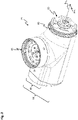
Figur 2 eine perspektivische Darstellung eines inFigur 1 -
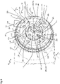
Figur 3 eine perspektivische Darstellung eines Ausschnitts des inFigur 2 gezeigten aktiven Armmoduls; -
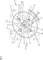
Figur 4 einen vergrößerten Ausschnitt einer inFigur 3 gezeigten ersten Anschlussseite des aktiven Armmoduls; -
Figur 5 eine perspektivische Darstellung des inFigur 2 gezeigten aktiven Armmoduls; -
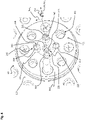
Figur 6 eine Draufsicht auf eine zweite Anschlussseite des inFigur 2 gezeigten aktiven Armmoduls; -
Figur 7 eine perspektivische Darstellung der inFigur 6 gezeigten zweiten Anschlussseite des aktiven Armmoduls; -
Figur 8 einen perspektivischen Halblängsschnitt durch das inFigur 2 gezeigte aktive Armmodul; -
Figur 9 eine perspektivische Schnittansicht entlang einer inFigur 3 gezeigten Schnittebene X-X durch das inFigur 3 gezeigte aktive Armmodul; -
Figur 10Figur 1Figur 1 -
Figur 11 eine Schnittansicht entlang einer inFigur 1den Figuren 1 gezeigte erste und zweite aktive Armmodul; -
Figur 12 einen inFigur 1Figur 1 -
Figur 13 einen Ausschnitt einer Schnittansicht entlang einer inFigur 1Figur 1 -
Figur 14 eine perspektivische Darstellung eines passiven Armmoduls gemäß einer ersten Ausführungsform. -
Figur 15 -
Figur 16 eine perspektivische Darstellung eines aktiven Armmoduls gemäß einer zweiten Ausführungsform; -
Figur 17 einen Längsschnitt durch einen Verbinder eines Roboterarms; und -
Figur 18Figur 15 -
Figur 1
-
figure 1 a perspective view of an industrial robot according to a first embodiment for an automation system; -
figure 2 a perspective view of afigure 1 shown active arm module of the robot arm according to a first embodiment; -
figure 3 a perspective view of a section of the infigure 2 active arm module shown; -
figure 4 an enlarged section of an infigure 3 shown first connection side of the active arm module; -
figure 5 a perspective view of the infigure 2 active arm module shown; -
figure 6 a plan view of a second connection side of the infigure 2 active arm module shown; -
figure 7 a perspective view of thefigure 6 shown second connection side of the active arm module; -
figure 8 a perspective half longitudinal section through the infigure 2 active arm module shown; -
figure 9 a perspective sectional view along an infigure 3 shown section plane XX through the infigure 3 active arm module shown; -
figure 10 a sectional view along an infigure 1 Section plane shown YY through a first active arm module and a second active arm module infigure 1 shown robot arm of the industrial robot; -
figure 11 a sectional view along an infigure 1 Section plane ZZ shown by the in thefigures 1 first and second active arm modules shown; -
figure 12 one infigure 1 marked section V of the infigure 1 shown industrial robot; -
figure 13 a detail of a sectional view along an infigure 1 shown cutting plane WW through the infigure 1 shown industrial robots; -
figure 14 a perspective view of a passive arm module according to a first embodiment. -
figure 15 a perspective view of a passive arm module according to a second embodiment. -
figure 16 a perspective view of an active arm module according to a second embodiment; -
figure 17 a longitudinal section through a connector of a robot arm; and -
figure 18 a cross-section through an infigure 15 shown clamping ring of the connector. -
figure 1 shows a perspective view of anindustrial robot 10 for an automation system.
Unter dem Industrieroboter 10 wird eine (automatische) Maschine mit mehreren Freiheitsgraden (in
Der vorliegende Roboterarm 20 des Industrieroboters 10 ist insbesondere modular aus einem Modulbaukasten mit einer Mehrzahl von Armmodulen 18 ausgebildet. Die Armmodule 18 können als aktives Armmodul 25 oder als passives Armmodul 30 oder als Endeffektor beispielhaft aufgebaut sein. Der Modulbaukasten kann ferner weitere (Arm- und/oder End-)Module aufweisen. Prinzipiell ist der Aufbau des Roboterarms 20 mit aktiven Armmodulen 25 und passiven Armmodulen 30 beliebig wählbar und ist nur hinsichtlich einer maximalen Tragkraft der Armmodule 18 beschränkt.The
In
Analog dazu wird bei den passiven Armmodulen 30 auf die Antriebseinrichtung verzichtet. Sie sind also als eine Art Verlängerungsteil ausgebildet.In a similar way, the
Der Roboterarm 20 umfasst in Abhängigkeit einer Anzahl von aktiven Armmodulen 25 auch eine entsprechende Anzahl von Rotationsachsen Ran. D. h., bevorzugt lassen sich eine beliebige Anzahl von vollständigen Umdrehungen eines betreffenden aktiven Armmoduls 25 des Roboterarms 20 in bevorzugt beide Umfangsrichtungen Uran einer betreffenden Rotationsachse Ran durchführen.Depending on a number of
Ferner bezieht sich die Erläuterung im Folgenden auf ein polares Koordinatensystem jeweils eines aktiven Armmoduls 25. Das polare Koordinatensystem weist dabei jeweils eine im Allgemeinen und nicht auf ein bestimmtes aktives Armmodul 25 verweisende Rotationsachse Ran auf. Entlang der Rotationsachse Ran verläuft eine Axialrichtung Aran des aktiven Armmoduls 25. Senkrecht nach außen bezogen auf die jeweilige Rotationsachse Ran verläuft eine Radialrichtung Rran des jeweiligen aktiven Armmoduls 25. Eine Umfangsrichtung Uran des jeweiligen aktiven Armmoduls 25 verläuft auf einer (Kreis-)Bahn um die Rotationsachse Ran des aktiven Armmoduls 25. Die allgemeine Nomenklatur wird verwendet, um im Allgemeinen den Aufbau des aktiven Armmoduls 25 zu erläutern.Furthermore, the explanation below refers to a polar coordinate system of an
Im Speziellen sind in
Ferner bezieht sich die Erläuterung im Folgenden auf ein weiteres polares Koordinatensystem jeweils eines passiven Armmoduls 30. Das weitere polare Koordinatensystem weist jeweils eine Längsachse Lan auf. Entlang der Längsachse Lan verläuft eine Axialrichtung Arpn des jeweiligen passiven Armmoduls 30.Furthermore, the explanation below refers to a further polar coordinate system of a
Einer jeweiligen Rotationsachse Ran des aktiven Armmoduls 25 ist bevorzugt ein Kraft- und/oder Drehmomentsensor sowie ggf. eine erste und/oder zweite Sensoreinrichtung jeweils eines aktiven Armmoduls 25 zugeordnet, mit dem eine Kraft und/oder ein Drehmoment auf das aktive Armmodul 25 sowie eine Position des aktiven Armmoduls 25 gegenüber der Rotationsachse Ran erfassbar ist. Die Rotationsachse Ran ist beispielhaft als ideelles "Gelenk" (Rotationsgelenk, Drehgelenk und/oder Schwenkgelenk) des mehrgliedrigen bzw. bevorzugt modular aufgebauten Roboterarms 20, z. B. gegenüber der Roboterbasis 15, ausgebildet.A force and/or torque sensor and, if necessary, a first and/or second sensor device of an
Für die jeweilige Rotationsachse Ran kann ein Kraft-, Drehmoment- und/oder Positionssensor für eine Überwachung von am Roboterarm 20 auftretenden Kräften und/oder Drehmomenten und/oder einer Relativposition der Armmodule 18 zueinander vorgesehen sein. Dies kann auch auf einen Abschnitt des Roboterarms 20 beschränkbar sein.A force, torque and/or position sensor for monitoring forces and/or torques occurring on the
Vorliegend weist ein bestimmter Modulbaukasten für einen Roboterarm 20 wenigstens einen Typ eines beispielweise I-, J-, L- bzw. T-förmig ausgebildeten, aktiven Armmoduls 25 und vorzugsweise wenigstens einen Typ eines beispielsweise I-, J-, L- bzw. T-förmig ausgebildeten, passiven Armmoduls 30 auf. Beispielhaft sind in
In
Zur eindeutigen Identifizierung der jeweiligen ersten bis vierten Anschlussseite 40, 45, 50, 55 erfolgt die Zuordnung der ersten bis vierten Anschlussseiten 40, 45, 50, 55 korrespondierend zu der Nummerierung der aktiven Armmodule 25 oder der passiven Armmodule 30. So ist die erste Anschlussseite des ersten aktiven Armmoduls 25.1 mit dem Bezugszeichen 40.1 in
Die erste Anschlussseite 40, die zweite Anschlussseite 45, die dritten Anschlussseiten 50 und die vierten Anschlussseiten 55 sind korrespondierend zueinander ausgebildet. D. h., dass an jede erste Anschlussseite 40 eines aktiven Armmoduls 25 eine zweite Anschlussseite 45 eines anderen aktiven Armmoduls 25 oder eine dritte Anschlussseite 50 eines passiven Armmoduls 30 anschließbar wäre. Ebenso wäre an jede zweite Anschlussseite 45 eines aktiven Armmoduls 25 eine erste Anschlussseite 40 eines anderen aktiven Armmoduls 25 oder eine vierte Anschlussseite 55 eines passiven Armmoduls 30 anschließbar.The
In
Eine zweite Anschlussseite 45.1 des ersten aktiven Armmoduls 25.1 ist mit einer ersten Anschlussseite 40.2 des zweiten aktiven Armmoduls 25.2 verbunden. Zwischen einer zweiten Anschlussseite 45.2 des zweiten aktiven Armmoduls 25.2 und einer zweiten Anschlussseite 45.3 des dritten aktiven Armmoduls 25.3 ist das erste passive Armmodul 30.1 angeordnet, wobei eine vierte Anschlussseite 55.1 des ersten passiven Armmoduls 30.1 mit der zweiten Anschlussseite 45.2 des zweiten aktiven Armmoduls 25.2 an einem Ende und am anderen Ende eine weitere vierte Anschlussseite 55.1 des ersten passiven Armmoduls 30.1 mit einer zweiten Anschlussseite 45.3 des dritten aktiven Armmoduls 25.3 verbunden ist. In der Ausführungsform sind somit beispielhaft beide Anschlussseiten des ersten passiven Armmoduls 30.1 als vierte Anschlussseiten 55.1 des ersten passiven Armmoduls 30.1 und somit korrespondierend und/oder komplementär zu der zweiten Anschlussseite 45.2 des zweiten aktiven Armmoduls 25.2 und der zweiten Anschlussseite 45.3 des dritten aktiven Armmoduls 25.3 ausgebildet. Dadurch kann die zweite Anschlussseite 45.2 des zweiten aktiven Armmoduls 25.2 zu der zweiten Anschlussseite 45.3 des dritten aktiven Armmoduls 25.3 auf einfache Weise beabstandet angeordnet sein und eine vordefinierte Gestaltung des Roboterarms 20 auf einfache Weise umgesetzt werden. Beispielhaft ist in
Ein zweites passives Armmodul 30.2 ist beispielhaft unterschiedlich in dem Modulbaukasten zu dem ersten passiven Armmodul 30.1 ausgebildet. In Axialrichtung des zweiten passiven Armmoduls 30.2 ist das zweite passive Armmodul 30.2 kürzer als das erste passive Armmodul 30.1 ausgebildet. Ferner ist eine dritte Anschlussseite 50.2 des zweiten passiven Armmoduls 30.2 identisch zu der zweiten Anschlussseite 45.4 des vierten aktiven Armmoduls 25.4 und eine vierte Anschlussseite 55.2 des zweiten passiven Armmoduls 30.2 korrespondierend und/oder komplementär zu der zweiten Anschlussseite 45.5 des fünften aktiven Armmoduls 25.5 und somit identisch zu der ersten Anschlussseite 40.5 des fünften aktiven Armmoduls 25.5 ausgebildet. Somit weist im Unterschied zu dem ersten passiven Armmodul 30.1 das zweite passive Armmodul 30.2 an seinen Enden jeweils die dritte Anschlussseite 50.2 und die vierte Anschlussseite 55.2 des zweiten passiven Armmoduls 30.2 auf, die zueinander unterschiedlich sind.A second passive arm module 30.2 is, for example, designed differently in the modular system than the first passive arm module 30.1. In the axial direction of the second passive arm module 30.2, the second passive arm module 30.2 is shorter than the first passive arm module 30.1. Furthermore, a third connection side 50.2 of the second passive arm module 30.2 is identical to the second connection side 45.4 of the fourth active arm module 25.4 and a fourth connection side 55.2 of the second passive arm module 30.2 corresponds to and/or complements the second connection side 45.5 of the fifth active arm module 25.5 and is therefore identical formed to the first connection side 40.5 of the fifth active arm module 25.5. Thus, in contrast to the first passive arm module 30.1, the second passive arm module 30.2 has at its ends the third connection side 50.2 and the fourth connection side 55.2 of the second passive arm module 30.2, which are different from one another.
An der ersten Anschlussseite 40.5 des fünften aktiven Armmoduls 25.5 ist das fünfte aktive Armmodul 25.5 mit einer zweiten Anschlussseite 45.6 des sechsten aktiven Armmoduls 25.6 verbunden. Eine erste Anschlussseite 40.6 des sechsten aktiven Armmoduls 25.6 ist mit dem Endeffektor verbunden.On the first connection side 40.5 of the fifth active arm module 25.5, the fifth active arm module 25.5 is connected to a second connection side 45.6 of the sixth active arm module 25.6. A first connection side 40.6 of the sixth active arm module 25.6 is connected to the end effector.
Über die Armmodule 18 und deren ersten bis vierten Anschlussseiten 40, 45, 50, 55 wird der Endeffektor wie im Weiteren noch ausführlich beschrieben mit dem Fluid 51 versorgt und ist mit der elektrischen Energiequelle 52 elektrisch und mit dem Datennetzwerk 53 datentechnisch verbunden. Ebenso sind die aktiven und passiven Armmodule 25, 30 über ihre ersten bis vierten Anschlussseiten 40, 45, 50, 55 mit dem Datennetzwerk 53, beispielsweise mit einem Feldbus oder einem EtherCAT-Netzwerk, datentechnisch und mit der elektrischen Energiequelle 52 leistungstechnisch verbunden. Jedes der aktiven Armmodule 25 weist ein erstes Gehäuse 60 auf, wobei jedes der ersten Gehäuse 60 jeweils einen ersten Gehäuseinnenraum 65 innenseitig begrenzt. An einem Ende des ersten Gehäuses 60 ist jeweils die erste Anschlussseite 40 angeordnet. Die erste Anschlussseite 40 ist drehbar um die Rotationsachse Ran gegenüber dem ersten Gehäuse 60 gelagert und wird steuerbar durch die Antriebseinrichtung des jeweiligen aktiven Armmoduls 25 angetrieben. Die zweite Anschlussseite 45 ist beispielsweise geneigt, vorzugsweise senkrecht gegenüber der ersten Anschlussseite 40 ausgerichtet und drehfest mit dem ersten Gehäuse 60 verbunden. Im ersten Gehäuseinnenraum 65 sind Mittel zur fluidischen, elektrischen und datentechnischen Verbindung der ersten Anschlussseite 40 mit der zweiten Anschlussseite 45 angeordnet, auf die detailliert an späterer Stelle eingegangen wird.The end effector is supplied with the fluid 51 via the
Bei Aktivierung der Antriebseinrichtung des aktiven Armmoduls 25 verdreht die Antriebseinrichtung die erste Anschlussseite 40 relativ zum ersten Gehäuse 60. Je nach Ausgestaltung des Roboterarms 20 verschwenkt die Antriebseinrichtung somit das aktive Armmodul 25 mit Ausnahme der eigenen ersten Anschlussseite 40 um die zugeordnete Rotationsachse Ran oder nur die erste Anschlussseite 40 um die zugeordnete Rotationsache Ran.When the drive device of the
In
Bei dem in
Es ist natürlich möglich, die jeweilige Rotationsachse Ran auch nur als eine Schwenkachse auszubilden, d. h. eine Bewegung des betreffenden aktiven Armmoduls 25 ist auf einen bestimmten Winkel beschränkt, wie z. B. auf Winkel kleiner als: 720°, 540°, 360°, 270°, 180°, 90° oder 45°. In
Die passiven Armmodule 30 weisen jeweils ein zweites Gehäuse 70 auf, wobei das zweite Gehäuse 70 hohlkörperartig ausgebildet ist und sich entlang der Längsachse Lan in Axialrichtung Arpn erstreckt. In
Im Modulbaukasten kann das Armmodul 18 unterschiedliche Größen aufweisen. Insbesondere kann das erste oder zweite Gehäuse 60, 70 verschiedene Längen und/oder unterschiedliche Querschnittsflächen der ersten bis vierten Anschlussseiten 40, 45, 50, 55 aufweisen, um so eine gewünschte geometrische Ausgestaltung des Roboterarms 20 bei der Kombination der Armmodule 18 aus dem Modulbaukasten auf einfache Weise zu erhalten.In the modular system, the
Der Modulbaukasten kann dabei derart gestaltet sein, dass die Armmodule 18 jeweils unterschiedlichen Baugruppen angehören, die unterschiedliche geometrische Ausgestaltungen aufweisen, jedoch funktionell identisch zueinander aufgebaut sind.The modular system can be designed in such a way that the
In der Ausführungsform sind das erste aktive Armmodul 25.1 und das zweite aktive Armmodul 25.2 identisch ausgebildet und weisen in konstruktiver Ausgestaltung die gleiche geometrische Ausgestaltung auf. In
Das dritte aktive Armmodul 25.3 und das vierte aktive Armmodul 25.4 sind geometrisch in der konstruktiven Ausgestaltung kleiner ausgebildet als das erste und zweite aktive Armmodul 25.1, 25.2, damit Momente und Kräfte für das erste und zweite aktive Armmodul 25.1 und 25.2 reduziert sind. Sie gehören einer zweiten Baugruppe an. Ebenso sind das fünfte aktive Armmodul 25.5 und das sechste aktive Armmodul 25.6 einer dritten Baugruppe zugehörig, die die kleinste Ausgestaltung aufweist. Dadurch, dass die Armmodule 18 mit zunehmendem Abstand von der Roboterbasis 15 kleineren Baugruppen zugehören, wird das an der Roboterbasis 15 angeschlossene passive Armmodul 30, in der Ausführungsform das dritte passive Armmodul 30.3, mechanisch entlastet.The third active arm module 25.3 and the fourth active arm module 25.4 are geometrically smaller than the first and second active arm module 25.1, 25.2, so that moments and forces for the first and second active arm module 25.1 and 25.2 are reduced. They belong to a second group. Likewise, the fifth active arm module 25.5 and the sixth active arm module 25.6 belong to a third assembly, which has the smallest configuration. Due to the fact that the
Die oben beschriebene Ausgestaltung des Modulbaukastens hat den Vorteil, dass auf einfache Weise mittels der einzelnen aktiven Armmodule 25 und gegebenenfalls mindestens einem passiven Armmodul 30 ein mehrachsiger Roboterarm 20 individuell auf die Bedürfnisse aus den aktiven bzw. passiven Armmodulen 25, 30 des Modulbaukastens maßgeschneidert zusammengestellt werden kann.The configuration of the modular system described above has the advantage that a
Durch die Fertigung der Armmodule 18 unabhängig von dem Roboterarm 20 kann der in
Ferner kann auf die Anordnung von Leitungen, Kabeln oder anderen Verbindungsmitteln außenseitig an dem Industrieroboter 10 durch die innenseitige Führung des Fluids 51, der elektrischen Energie und die datentechnische Verbindung verzichtet werden, sodass eine ungewollte Beschädigung des Industrieroboters 10 vermieden werden kann.Furthermore, the arrangement of lines, cables or other connecting means on the outside of the
Das aktive Armmodul 25 ist auch über die Baugruppen hinweg jeweils identisch aufgebaut, wobei jedoch abweichend dadurch nur die geometrische Ausgestaltung entsprechend angepasst ist. Mit anderen Worten sind die aktiven J-förmig ausgebildeten aktiven Armmodule 25 der unterschiedlichen Baugruppen gegenüber einander skaliert ausgebildet.The
In der Ausführungsform ist die erste Anschlussseite 40 in einer Rotationsebene senkrecht zu der Rotationsachse Ran angeordnet. Die zweite Anschlussseite 45 ist geneigt radial außen zu der Rotationsachse Ran angeordnet und geneigt, vorzugsweise senkrecht, zu der ersten Anschlussseite 40 ausgerichtet.In the embodiment, the
Das erste Gehäuse 60 weist einen im Wesentlichen zylinderförmig ausgebildeten ersten Gehäuseabschnitt 80 auf. Der erste Gehäuseabschnitt 80 erstreckt sich im Wesentlichen um die Rotationsachse Ran. Seitlich an einer Umfangsseite des ersten Gehäuseabschnitts 80 ist am ersten Gehäuseabschnitt 80 ein zweiter Gehäuseabschnitt 85 angeordnet, wobei in Axialrichtung Aran der zweite Gehäuseabschnitt 85 schmaler ausgebildet ist als der erste Gehäuseabschnitt 80. Der zweite Gehäuseabschnitt 85 ist im Wesentlichen wannenförmig ausgebildet. An einer dem ersten Gehäuseabschnitt 80 abgewandten Seite ist die zweite Anschlussseite 45 am zweiten Gehäuseabschnitt 85 angeordnet. Dabei ragt die zweite Anschlussseite 45 über den zweiten Gehäuseabschnitt 85 heraus. Die zweite Anschlussseite 45 kann außermittig bezogen auf eine maximale Längserstreckung in Axialrichtung Aran angeordnet sein. Besonders kompakt und eine besonders günstige Kraftübertragung zwischen der ersten Anschlussseite 40 und der zweiten Anschlussseite 45 ist gegeben, wenn in Axialrichtung Aran die zweite Anschlussseite 45 anschließend an die erste Anschlussseite 40 am ersten Gehäuse 60 angeordnet ist. Insbesondere ist dadurch eine Biegebeanspruchung des ersten Gehäuses 60 zur Kraftübertragung besonders gering.The
Die erste Anschlussseite 40 weist eine erste Anschlussplatte 95 auf. Die erste Anschlussplatte 95 ist beispielhaft kreisförmig in der Draufsicht ausgebildet und erstreckt sich senkrecht zu einer ersten Montageachse 100, wobei die erste Montageachse 100 bei einer Ausgestaltung des Armmoduls als aktives Armmodul 25 als Rotationsachse Ran ausgebildet ist. Mit anderen Worten überdecken sich die erste Montageachse 100 und die Rotationsachse Ran.The
An einer ersten äußeren Umfangsseite 105 weist die erste Anschlussplatte 95 vorzugsweise ein Außengewinde 110 auf. Das Außengewinde 110 ist mehrgängig ausgebildet. Von besonderem Vorteil ist hierbei, wenn das Außengewinde 110 wenigstens drei-, vorzugsweise viergängig ist. Ferner ist von Vorteil, wenn das Außengewinde 110 als Feingewinde ausgebildet ist.The
Die erste Anschlussseite 40 weist eine erste Kontaktseite 101 auf. Die erste Kontaktseite 101 weist eine erste Stirnseite 115 und eine zweite Stirnseite 155 auf, wobei die erste Stirnseite 115 radial außen zur zweiten Stirnseite 155 angeordnet ist.The
In Radialrichtung Rran schließt sich nach innen hin an die erste äußere Umfangsseite 105 an der ersten Stirnseite 115 der ersten Anschlussplatte 95 eine erste Stirnverzahnung 116 an. Die erste Stirnverzahnung 116 ist in der Ausführungsform als selbstzentrierende Stirnverzahnung beispielhaft als Hirth-Verzahnung ausgebildet. Dabei weist die erste Stirnverzahnung 116 mehrere in Umfangsrichtung versetzt angeordnete erste Zähne 120 auf, die in der Ausführungsform beispielhaft identisch zueinander ausgebildet sind. Ein erster Zahnkopf 121 des ersten Zahns 120 ist plan ausgebildet und verläuft in einer Rotationsebene senkrecht zu der Rotationsachse Ran und somit parallel zu der ersten Stirnseite 115. Ein erster Zahngrund 122, der in Umfangsrichtung Uran zwischen zwei ersten Zähnen 120 angeordnet ist, wird durch die erste Stirnseite 115 ausgebildet. Jede der ersten Zahnflanken 123 des ersten Zahns 120 ist hin zur Rotationsachse Ran mit wenigstens einer Richtung orientiert. Der erste Zahngrund 122 ist in Umfangsrichtung zwischen zwei zugewandten ersten Zahnflanken 122 angeordnet. Zwischen zwei ersten Zähnen 120 ist jeweils ein erster Zahnzwischenraum 124 angeordnet, der in Umfangsrichtung durch die ersten Zahnflanken 123 und in axialer Richtung durch den ersten Zahngrund 122 begrenzt wird.A
Beispielsweise radial innenseitig zu der ersten Stirnverzahnung 116 ist wenigstens ein erstes Befestigungsmittel 140 angeordnet. Das erste Befestigungsmittel 140 kann beispielsweise als erste Schraube ausgebildet sein. Ein erster Schraubenkopf der ersten Schraube kann in der ersten Anschlussplatte 95 versenkt sein. Vorzugsweise sind mehrere erste Befestigungsmittel 140 an der ersten Anschlussplatte 95 angeordnet, wobei jedes der ersten Befestigungsmittel 140 radial innenseitig zum ersten Zahn 120 angeordnet ist. Das erste Befestigungsmittel 140 ist auf einer ersten Kreisbahn 145 um die Rotationsachse Ran verlaufend angeordnet. Dabei sind beispielhaft pro ersten Zahn 120 jeweils zwei erste Befestigungsmittel 140 radial innenseitig eines ersten Zahns 120 angeordnet. Ferner kann in dem ersten Zahn 120 wenigstens eine erste Einbuchtung 125 angeordnet sein. Die erste Einbuchtung 125 kann bohrungsartig ausgebildet sein. Die erste Einbuchtung 125 kann radial nach innen zu einer inneren Zahnumfangsseite 130 des ersten Zahns 120 offen sein. In Axialrichtung Aran erstreckt sich die erste Einbuchtung 125 bis etwa auf Höhe der ersten Stirnseite 125, sodass ein Einbuchtungsgrund der ersten Einbuchtung 125 und die erste Stirnseite 115 stufenlos übergehen. In der Ausführungsform sind beispielhaft pro ersten Zahn 120 jeweils zwei identisch zueinander ausgebildete erste Einbuchtungen 125 vorgesehen. Die ersten Einbuchtungen 125 können auf einer gemeinsamen vierten Kreisbahn 335 um die Rotationsachse Ran angeordnet sein.At least one first fastening means 140 is arranged, for example, radially on the inside of the
Radial innenseitig zu dem ersten Befestigungsmittel 140 weist die erste Anschlussseite 40 ein erstes Anschlusselement 150 auf. Das erste Anschlusselement 150 weist die zweite Stirnseite 155 auf, wobei die zweite Stirnseite 155 parallel verlaufend zur ersten Stirnseite 115 ausgebildet ist. Das erste Anschlusselement 150 ist mittels wenigstens eines zweiten Befestigungsmittels 160, vorzugsweise mehrere in Umfangsrichtung Uran versetzt zueinander auf einer zweiten Kreisbahn 165 um die Rotationsachse Ran, angeordnet. Das zweite Befestigungsmittel 160 ist beispielsweise als zweite Schraube ausgebildet, wobei ein zweiter Schraubenkopf des zweiten Befestigungsmittels 160 in dem ersten Anschlusselement 150 versenkt ist.The
Die zweite Kreisbahn 165 und die erste Kreisbahn 145 sind konzentrisch zueinander angeordnet. Dabei liegt jeweils ein Mittelpunkt auf der Rotationsachse Ran und somit auf der ersten Montageachse 100. In Umfangsrichtung Uran sind beispielsweise drei zweite Befestigungsmittel 160 in jeweils 90°-Winkel bezogen auf die Rotationsachse Ran zueinander angeordnet, sodass zwischen zwei zweiten Befestigungsmitteln 160 ein Winkel von 180° beispielhaft vorliegt.The second
Das erste Anschlusselement 150 weist in Umfangsrichtung Uran zwischen den beiden zweiten Befestigungsmitteln 160, die beispielhaft im 180°-Abstand zueinander angeordnet sind, eine erste Stiftaufnahme 170 auf. Die erste Stiftaufnahme 170 ist beispielhaft als Durchgangsöffnung ausgebildet und in Umfangsrichtung Uran mittig auf der zweiten Kreisbahn 165 zwischen den beiden um beispielhaft 180° angeordneten zweiten Befestigungsmitteln 160 angeordnet.The first connecting
Die erste Anschlussseite 40 weist ferner einen Stift 175 auf, wobei der Stift 175 rückseitig (in
Die erste Anschlussplatte 95 weist wenigstens einen der folgenden ersten Werkstoffe auf: Metall, Aluminium, Stahl, Titan-Aluminiumlegierung, hochfeste Aluminiumlegierung, AW7075, faserverstärkter Kunststoff, Glasfaserverstärkter Kunststoff (GfK), Kohlenstofffaserverstärkter Kunststoff (CfK). Das erste Anschlusselement 150 weist wenigstens einen der zweiten folgenden Werkstoffe auf: ein elektrisch nicht leitfähiges Material, Kunststoff, Thermoplast, Polyamid, PA GF30, PA6 GF 30. Der Stift 175 weist wenigstens einen der folgenden dritten Werkstoffe auf: Metall, Aluminium, Stahl, elektrisch leitfähiger Kunststoff, Messing, Kupfer. Dadurch, dass rückseitig der Stift 175 in die erste Anschlussplatte 95 eingeschraubt ist, ist der Stift 175 elektrisch mit der ersten Anschlussplatte 95 verbunden. Ferner befestigt der Stift 175 das erste Anschlusselement 150 an der ersten Anschlussplatte 95.The first connecting
Das erste Anschlusselement 150 weist ferner eine erste Fluidkontakteinrichtung 180 auf. Die erste Fluidkontakteinrichtung 180 ist in der Ausführungsform beispielhaft als Buchse bzw. Weibchen ausgebildet. Dabei weist die erste Fluidkontakteinrichtung 180 wenigstens einen ersten Fluidkontakt 185 auf. In der beispielhaften Ausführungsform weist die Fluidkontakteinrichtung 180 neben dem ersten Fluidkontakt 185 noch einen zweiten bis vierten Fluidkontakt 186 bis 188 auf.The
Jeder der ersten bis vierten Fluidkontakte 185 bis 188 ist vom jeweils anderen ersten bis vierten Fluidkontakt 185 bis 188 fluidisch getrennt. Der erste bis vierte Fluidkontakt 185 bis 188 wird in der Ausführungsform durch eine als Sackloch in dem ersten Anschlusselement 150 ausgebildete Rohraufnahme 190 ausgebildet. Die ersten bis vierten Fluidkontakte 185 bis 188 sind identisch zueinander ausgebildet.Each of the first through fourth fluid contacts 185-188 is fluidically isolated from the other first through fourth fluid contacts 185-188. In the embodiment, the first to fourth
Die Rohraufnahme 190 mündet an der zweiten Stirnseite 155. Die Rohraufnahme 190 weist an einer ersten inneren Umfangsseite eine Dichtfläche 195 auf. An einem Grund der Rohraufnahme 190 mündet jeweils ein Fluidverbindungskanal 200. Die Fluidverbindungskanäle 200 verlaufen fluidisch getrennt zueinander in der ersten Anschlussplatte 95. In Umfangsrichtung Uran sind der erste bis vierte Fluidkontakt 185 bis 188 zumindest teilweise auf der zweiten Kreisbahn 165 angeordnet. Dabei sind der erste bis vierte Fluidkontakt 185 bis 188 bezogen auf die zweite Kreisbahn 165 mit ihrer Mittelachse geringfügig nach innen hin versetzt angeordnet.The tube receptacle 190 opens out at the
In Umfangsrichtung Uran sind die ersten bis vierten Fluidkontakte 185 bis 188 um 90° zueinander versetzt angeordnet. Dabei sind beispielhaft jeweils einer der ersten bis vierten Fluidkontakte 185 bis 188 in Umfangsrichtung Uran mittig zwischen zwei zweiten Befestigungsmitteln 160 bzw. mittig zwischen dem Stift 175 und einem in Umfangsrichtung Uran nächstliegend zu dem Stift 175 angeordneten zweiten Befestigungsmittel 160 angeordnet.The first to fourth
Radial innenseitig zu der zweiten Kreisbahn 165 und somit auch zu der ersten Fluidkontakteinrichtung 180 und dem zweiten Befestigungsmittel 160 weist die erste Anschlussseite 40 an dem ersten Anschlusselement 150 eine erste Leistungskontakteinrichtung 205 auf.The
Die erste Anschlussseite 40 weist ferner eine erste Kontakteinrichtung 220 auf, wobei die erste Kontakteinrichtung 220 zur Datenübertragung ausgebildet ist und beispielhaft ein erstes Kontaktelement 225 aufweist. Das erste Kontaktelement 225 ist auf der ersten Montageachse 100 verlaufend angeordnet und erstreckt sich längs der ersten Montageachse 100. Das erste Kontaktelement 225 ist beispielhaft lichtleitend und zur Übertragung des optischen Signals ausgebildet.The
Die erste Kontakteinrichtung 220 ist als Buchse ausgebildet und weist eine Kontaktaufnahme 230 auf, wobei die Kontaktaufnahme 230 sacklochartig in dem ersten Anschlusselement 150 ausgebildet ist, wobei sich das erste Kontaktelement 225 in der Kontaktaufnahme 230 erstreckt. Die erste Kontaktaufnahme 230 mündet an der zweiten Stirnseite 155.The
Durch die mittige Anordnung der ersten Kontakteinrichtung 220 zur Datenübertragung ist die erste Leistungskontakteinrichtung 205 in Radialrichtung Rran zwischen der ersten Fluidkontakteinrichtung 180 und der ersten Kontakteinrichtung 220 angeordnet. Diese Ausgestaltung hat den Vorteil, dass die erste Anschlussseite 40 in Radialrichtung Rran einen besonders niedrigen Bauraumbedarf aufweist.Due to the central arrangement of the
Die erste Leistungskontakteinrichtung 205 weist beispielhaft neben einem ersten Leistungskontakt 210 wenigstens einen zweiten Leistungskontakt 211, vorzugsweise auch einen dritten und vierten Leistungskontakt 212, 213 auf. Der erste bis vierte Leistungskontakt 210 bis 213 sind jeweils in Umfangsrichtung Uran beispielhaft in einem 90°-Winkel versetzt zueinander angeordnet. Für jeden ersten bis vierten Leistungskontakt 210, 211, 212, 213 weist das Anschlusselement 150 eine erste Leistungskontaktaufnahme 235 auf. Die erste Leistungskontaktaufnahme 235 ist als Durchgangsöffnung in dem ersten Anschlusselement 150 ausgebildet. Die erste Leistungskontaktaufnahme 235 mündet in der zweiten Stirnseite 155. Jeder des ersten bis vierten Leistungskontakts 210 bis 213 ist beispielhaft identisch zu dem anderen ersten bis vierten Leistungskontakt 210 bis 213 ausgebildet.The first
Jeder erste bis vierte Leistungskontakt 210 bis 213 ist buchsenförmig ausgebildet. Der erste bis vierte Leistungskontakt 210 bis 213 ragt über die erste Stirnseite 155 hinaus und weist an einer inneren Umfangsseite jeweils eine zugeordnete Kontaktfläche 240, 245 auf. Die Kontaktfläche 240, 245 ist zylinderförmig ausgebildet. Die Kontaktfläche 240, 245 kann sich weiter über einen Boden des ersten bis vierten Leistungskontakts 210 bis 213 erstrecken. So weist beispielsweise der erste Leistungskontakt 210 eine erste Kontaktfläche 240 und der zweite Leistungskontakt 211 eine zweite Kontaktfläche 245 auf.Each of the first through
Beispielhaft kann der erste Leistungskontakt 210 mit einem im Allgemeinen als ersten Anschluss bezeichneten ersten Pol und der zweite Leistungskontakt 211 mit einem im Allgemeinen als zweiten Anschluss bezeichneten zweiten Pol der elektrischen Energiequelle verbunden werden.For example, the
In der Draufsicht sind der erste bis vierte Leistungskontakt 210 bis 213 kreisförmig ausgebildet. Dabei ist eine Querschnittsfläche deutlich kleiner als die des ersten bis vierten Fluidkontakts. Elektrisch werden der erste bis vierte Leistungskontakt 210 bis 213 durch das elektrisch nicht leitfähige erste Anschlusselement 150 gegenüber einander elektrisch isoliert.In plan view, the first to
Dabei ist beispielhaft in Umfangsrichtung Uran jeweils der erste bis vierte Leistungskontakt 210 bis 213 gemeinsam in einer Ebene, in der die Rotationsachse Ran und das zweite Befestigungsmittel 160 angeordnet sind, angeordnet. Die ersten bis vierten Leistungskontakte 210 bis 213 sind beispielsweise konzentrisch auf einer dritten Kreisbahn 215 um die erste Montageachse 100 bzw. die Rotationsachse Ran angeordnet. Die erste Leistungskontakteinrichtung 205 ist ausgebildet, eine elektrische Leistung, beispielsweise zur Versorgung des aktiven Armmoduls 25 und/oder des passiven Armmoduls, mit elektrischer Energie zu übertragen.In this case, for example in the circumferential direction Ura n , the first to
Die elektrische Energiequelle kann beispielsweise als Gleichspannungsquelle ausgebildet sein. Zusätzlich können beispielsweise der erste und zweite Leistungskontakt 210, 211 mit jeweils einem Pol der Gleichspannungsenergiequelle verbunden sein. Der dritte und vierte Leistungskontakt 212, 213 können mit jeweils einem weiteren Pol einer weiteren Gleichspannungsenergiequelle oder einer Wechselspannungsenergiequelle verbunden sein, wobei die beiden Gleichspannungsenergiequellen beispielsweise eine unterschiedliche Spannung aufweisen können. Dadurch kann über die erste Anschlussseite 40 elektrische Leistung zweier elektrischer (unterschiedlicher) Energiequellen getrennt voneinander übertragen werden.The electrical energy source can be embodied as a DC voltage source, for example. In addition, for example, the first and
Die zweite Anschlussseite 45 ist drehfest mechanisch mit dem ersten Gehäuse 60 verbunden. Die zweite Anschlussseite 45 weist eine zweite Anschlussplatte 300, eine zweite Fluidkontakteinrichtung 305, eine zweite Kontakteinrichtung 310, eine zweite Leistungskontakteinrichtung 315 und eine zweite Kontaktseite 320 auf.The
Die zweite Anschlussplatte 300 ist beispielhaft parallel zu der ersten Montageachse 100 und der Rotationsachse Ran ausgerichtet. Die zweite Anschlussplatte 300 weist im Wesentlichen in der Draufsicht eine kreisförmige Ausgestaltung auf. Dabei ist eine zweite Montageachse 325 geneigt, vorzugsweise senkrecht zu der ersten Montageachse 100 ausgerichtet. Die zweite Kontaktseite 320 und die zweite Anschlussplatte 300 sind senkrecht zu der zweiten Montageachse 325 ausgerichtet. An der zweiten Anschlussplatte 300 sind die zweite Fluidkontakteinrichtung 305, die zweite Kontakteinrichtung 310 und die zweite Leistungskontakteinrichtung 315 befestigt. Die zweite Fluidkontakteinrichtung 305, die zweite Kontakteinrichtung 310 und die zweite Leistungskontakteinrichtung 315 erstrecken sich längs bzw. parallel zu der zweiten Montageachse 325.The
Die zweite Anschlussplatte 300 ist mittels eines dritten Befestigungsmittels 330, vorzugsweise mehreren in Umfangsrichtung bezogen auf die zweite Montageachse 325 versetzt zueinander angeordneten dritten Befestigungsmitteln 330, die beispielsweise als dritte Schrauben ausgebildet sein können, mit dem ersten Gehäuse 60 drehfest mechanisch verbunden. Die dritten Befestigungsmittel 330 sind auf der vierten Kreisbahn 335 umlaufend um die zweite Montageachse 325 beispielhaft in regelmäßigem Abstand angeordnet. Die dritte Schraube kann einen dritten Schraubenkopf 331 aufweisen, wobei der dritte Schraubenkopf 331 über eine zweite Stirnseite 380 der zweiten Kontaktseite 320 hervorragt und auf der zweiten Stirnseite 380 aufliegt. Der dritte Schraubenkopf 331 weist einen kleineren maximalen Außendurchmesser auf aus die erste Einbuchtung (in
Umfangsseitig wird die zweite Anschlussplatte 300 durch einen Befestigungsring 340 des aktiven Armmoduls 25 umgriffen. Der Befestigungsring 340 weist an einer zweiten inneren Umfangsseite 345 ein Innengewinde 350 auf, wobei das Innengewinde 350 korrespondierend oder zumindest komplementär zu dem Außengewinde 110 der ersten Anschlussseite 40 ausgebildet ist. Der Befestigungsring 340 ist axial fest gegenüber dem ersten Gehäuse 60 angeordnet. Der Befestigungsring 340 ist jedoch um die zweite Montageachse 325 gegenüber dem ersten Gehäuse 60 verdrehbar.The
Bei Montage beispielsweise des zweiten aktiven Armmoduls 25.2 an dem ersten aktiven Armmodul 25.1 (vgl.
Vorzugsweise weist der Befestigungsring 340 wenigstens einen der folgenden vierten Werkstoffe auf: Metall, Aluminium, Stahl, Titan, Aluminiumlegierung, hochfeste Aluminiumlegierung, AW7075, faserverstärkter Kunststoff, Glasfaserverstärkter Kunststoff (GfK), Kohlenstofffaserverstärkter Kunststoff (CfK).The
Besonders von Vorteil ist, wenn, insbesondere bei einer im Wesentlichen identischen Ausgestaltung des ersten Werkstoffs und des vierten Werkstoffs, an einer zweiten äußeren Umfangsseite 355, die in der Ausführungsform im Wesentlichen zylinderförmig ausgebildet ist, eine Werkzeugaufnahme 360 angeordnet ist, wobei die Werkzeugaufnahme 360 beispielhaft als Sackloch ausgebildet ist. Dadurch kann zur Demontage bzw. zum Verdrehen des Befestigungsrings 340 gegenüber dem Außengewinde 110 bzw. dem ersten Gehäuse 60 mittels eines Werkzeugs (in
Umfangsseitig umgreift der Befestigungsring 340 die zweite Anschlussplatte 300. Dabei weist innenseitig angrenzend an den Befestigungsring 340 die zweite Anschlussplatte 300 eine zweite Stirnverzahnung 365 auf. Die zweite Stirnverzahnung 365 ist vorzugsweise als Hirth-Verzahnung ausgebildet. Die zweite Stirnverzahnung 365 kann komplementär oder vorzugsweise korrespondierend zur ersten Stirnverzahnung 116 ausgebildet sein. Die zweite Stirnverzahnung 365 ist in radialer Richtung zwischen der vierten Kreisbahn 335 und/oder dem dritten Befestigungsmittel 300 und dem Befestigungsring 340 angeordnet. Das dritte Befestigungsmittel 300 verbindet die zweite Anschlussseite 45 mit dem ersten GehäuseThe
Die erste Stirnverzahnung 116 und die zweite Stirnverzahnung 365 sind korrespondierend zueinander ausgebildet. Die zweite Stirnverzahnung 365 weist mehrere in Umfangsrichtung versetzt zueinander angeordnete zweite Zähne 370 auf, die auf einem gemeinsamen Teilkreis um die zweite Montageachse 325 angeordnet sind. Zur kompakten Ausgestaltung der zweiten Anschlussseite 45 kann in jeweils einem zweiten Zahn 370 der zweiten Stirnverzahnung 365 eine zweite Einbuchtung 375 angeordnet sein, wobei in der zweiten Einbuchtung 375 jeweils ein drittes Befestigungsmittel 330 angeordnet ist. Die zweite Einbuchtung 375 ist radial nach innen hin offen ausgebildet. Die zweite Einbuchtung 375 ist korrespondierend zu dem zweiten Schraubenkopf 331 ausgebildet und nimmt den zweiten Schraubenkopf 331 auf.The
Jeder der zweiten Zähne 370 weist jeweils eine zweite Zahnflanke 371 auf. Zwischen den zweiten Zähnen 370 weist die zweite Stirnverzahnung 365 einen zweiten Zahngrund 372 auf, der sich in einer Ebene senkrecht zur zweiten Montageachse 325 erstreckt. Der zweite Zahngrund 372 und die dritte Stirnseite 380 sind in einer gemeinsamen Ebene angeordnet und stufenlos zueinander ausgebildet. Jeder der zweiten Zähne 370 weist einen zweiten Zahnkopf 373 auf, der plan ausgebildet ist und sich in einer Ebene senkrecht zu der zweiten Montageachse 325 erstreckt. In Umfangsrichtung bezogen auf die zweite Montageachse 325 ist jeweils zwischen in Umfangsrichtung bezogen auf die zweite Montageachse nächstliegend angeordnete zweiten Zähnen 370 jeweils ein zweite Zahnzwischenraum 374 angeordnet.Each of the
Die zweite Kontaktseite 320 ist im Wesentlichen korrespondierend zur ersten Kontaktseite ausgebildet. Dabei weist die zweite Kontaktseite 320 die dritte Stirnseite 380 und eine vierte Stirnseite 385 auf, wobei die dritte Stirnseite 380 radial innenseitig angrenzend an den Befestigungsring 340 angeordnet ist. Die dritte Stirnseite 380 weist in der Draufsicht eine etwa ringförmige Ausgestaltung auf, wobei an der dritten Stirnseite 380 die zweite Stirnverzahnung 365 und die dritten Befestigungsmittel 330 angeordnet sind.The
Zur Aufnahme des ersten Anschlusselements 150 weist die zweite Anschlussplatte 300 eine Anschlussaufnahme 390 auf. Die Anschlussaufnahme 390 ist korrespondierend zu dem ersten Anschlusselement 150 ausgebildet und wird an ihrem Grund durch die vierte Stirnseite 385 begrenzt.The
An der vierten Stirnseite 385 ist die zweite Fluidkontakteinrichtung 305 angeordnet. Die zweite Fluidkontakteinrichtung 305 ist korrespondierend zu der ersten Fluidkontakteinrichtung (vgl.
In der Ausführungsform sind der fünfte bis achte Fluidkontakt 395 bis 398 beispielhaft um 90° in Umfangsrichtung versetzt bezogen auf die zweite Montageachse 325 auf einer fünften Kreisbahn 400 um die zweite Montageachse 325 angeordnet. Zwischen dem sechsten Fluidkontakt 396 und dem in Umfangsrichtung nächstliegend zum sechsten Fluidkontakt 396 angeordneten siebten Fluidkontakt 397 ist beispielhaft mittig eine zweite Stiftaufnahme 405 in der zweiten Anschlussplatte 300 angeordnet. Die zweite Stiftaufnahme 405 kann beispielsweise als Sackloch oder als Bohrung in der zweiten Anschlussplatte 300 ausgebildet sein. Die zweite Stiftaufnahme 405 ist korrespondierend zu dem Stift 175 (vgl.
Die zweite Kontakteinrichtung 310 ist auf der zweiten Montageachse 325 angeordnet und erstreckt sich längs der zweiten Montageachse 325.The
Radial zwischen der zweiten Kontakteinrichtung 310 und der zweiten Fluidkontakteinrichtung 305 ist die zweite Leistungskontakteinrichtung 315 angeordnet. Die zweite Leistungskontakteinrichtung 315 ist korrespondierend zur ersten Leistungskontakteinrichtung 205 ausgebildet und ist in der Ausführungsform steckerförmig bzw. als männliche Ausgestaltung ausgebildet.The second
Die zweite Kontakteinrichtung 310 ist als Stecker/Männchen und korrespondierend zur ersten Kontakteinrichtung 220 ausgebildet. Die zweite Kontakteinrichtung 310 weist ein zweites Kontaktelement 421 auf, wobei das zweite Kontaktelement 421 zentral auf der zweiten Montageachse 325 angeordnet ist und hülsenförmig ausgebildet ist. Zusätzlich kann in dem zweiten Kontaktelement 421 wenigstens eine in
Dabei weist die zweite Leistungskontakteinrichtung 315 einen korrespondierend zum ersten Leistungskontakt ausgebildeten fünften Leistungskontakt 410 auf, wobei der fünfte Leistungskontakt 410 stiftförmig ausgebildet ist. Umfangsseitig und/oder stirnseitig weist der fünfte Leistungskontakt 410 eine dritte Kontaktfläche 415 auf. Der fünfte Leistungskontakt 410 ist ein einer zweiten Leistungskontaktaufnahme 409 angeordnet und gegenüber der vierten Stirnseite 385 zurückversetzt. Der fünfte Leistungskontakt 410 kann gefedert in der zweiten Kontaktaufnahme 409 befestigt sein.The second
Die zweite Leistungskontakteinrichtung 315 weist neben dem fünften Leistungskontakt 410 auch noch beispielhaft einen sechsten, siebten und achten Leistungskontakt 411, 412, 413, auf, die ebenso als stiftförmig beispielhaft ausgebildet sind und in der Ausführungsform identisch zum fünften Leistungskontakt 410 ausgebildet sind. Auch der sechste bis achte Leistungskontakt 411 bis 413 sind in jeweils einer zweiten Leistungskontaktaufnahme 409 zurückversetzt angeordnet. Die zurückversetzte Anordnung des fünften bis achten Leistungskontakts 410, 411, 412, 413 schützt den fünften bis achten Leistungskontakt 410, 411, 412, 413 vor Berührung.In addition to the
In Radialrichtung Raran±1 bezogen auf die zweite Montageachse 325 zwischen der zweiten Fluidkontakteinrichtung 305 und der zweiten Kontakteinrichtung 310 sind der fünfte bis achte Leistungskontakt 410, 411, 412, 413 auf der sechsten Kreisbahn 420 um die zweite Montageachse 325 konzentrisch angeordnet.In the radial direction Rara n±1 relative to the
Der fünfte bis achte Fluidkontakt 395 bis 398 sind in der Ausführungsform beispielhaft identisch zueinander ausgebildet. Dabei ist der fünfte Fluidkontakt 395 beispielhaft rohrförmig ausgebildet. Der fünfte Fluidkontakt 395 erstreckt sich parallel zur zweiten Montageachse 325. Dabei ist mit einem festen Ende der fünfte Fluidkontakt 395 mit der vierten Stirnseite 385 verbunden. Der fünfte Fluidkontakt 395 ist beispielhaft als Männchen ausgebildet. Dabei mündet der zweite Fluidkontakt 395 beabstandet auf einer zur vierten Stirnseite 385 abgewandten Seite. Umfangsseitig weist jeweils der fünfte Fluidkontakt 395 ein erstes Dichtelement 425 auf, vorzugsweise einen O-Ring, der in einer Nut beispielsweise des fünften Fluidkontakts 395 umfangsseitig angeordnet sein kann.The fifth to eighth
Das aktive Armmodul 25 weist in dem ersten Gehäuse 60 eine Antriebseinrichtung 430, eine Übergabeeinrichtung 435, ein Steuergerät 445 und wenigstens einen Umsetzer 450 auf.The
Die Antriebseinrichtung 430 weist eine elektrische Maschine 455 und ein Getriebe 460 auf, wobei das Getriebe 460 eingangsseitig mit der elektrischen Maschine 455 verbunden ist. Ausgangseitig weist das Getriebe 460 einen Abtriebsflansch 491 auf. Der Abtriebsflansch 461 ist mittels des ersten Befestigungsmittels 140 mit der Anschlussplatte 95 drehfest verbunden. Dabei ist beispielsweise eine Schraube des ersten Befestigungsmittels 140 in den Abtriebsflansch 461 eingeschraubt. Im Betrieb der elektrischen Maschine 455 treibt die elektrische Maschine 455 mit einer Motordrehzahl das Getriebe 460 an. Das Getriebe 460 untersetzt, vorzugsweise mit einem Untersetzungsverhältnis von 1:30 bis 1:200, die Motordrehzahl auf eine Abtriebsdrehzahl. Die Abtriebsdrehzahl liegt an dem Abtriebsflansch 461 an. Der Abtriebsflansch 461 des Getriebes 460 treibt die erste Anschlussseite 40 über das erste Befestigungsmittel 140 und hierbei insbesondere die erste Anschlussplatte 95 an. Dabei ist das Getriebe 460 axial zwischen der elektrischen Maschine 455 und der ersten Anschlussseite 40 bezogen auf die Rotationsachse Ran angeordnet, die mit der ersten Montageachse 100 überlappt. Durch die drehfeste Verbindung mit der ersten Anschlussplatte 95 ist die erste Hohlwelle 470 mit dem Abtriebsflansch 461 drehfest gekoppelt und rotiert mit der Abtriebsdrehzahl. Axial auf einer der ersten Anschlussseite 40 abgewandten Seite der Antriebseinrichtung 430 ist die Übergabeeinrichtung 435 angeordnet. Die Übergabeeinrichtung 435 ist vorzugsweise in der Ausführungsform beispielhaft mit mehreren Schlauchleitungen 465 fluidisch ausgangsseitig mit der zweiten Fluidkontakteinrichtung 305 verbunden. In axialer Richtung bezogen auf die Rotationsachse Ran ist das Steuergerät 445 am gegenüberliegenden Ende des ersten Gehäuses 60 zu der ersten Anschlussseite 40 angeordnet.The
In
Die erste Anschlussseite 40 weist ferner eine erste Hohlwelle 470 auf. Die Antriebseinrichtung 430 weist ferner eine zweite Hohlwelle 475 auf, wobei die zweite Hohlwelle 475 die elektrische Maschine 455 mit dem Getriebe 460 verbindet. Die zweite Hohlwelle 475 läuft somit mit der Motordrehzahl und die erste Hohlwelle 470 mit der Abtriebsdrehzahl.The
Die zweite Hohlwelle 475 ist in axialer Richtung kürzer ausgebildet als die erste Hohlwelle 470. Die erste Hohlwelle 470 erstreckt sich dabei im Wesentlichen in Längsrichtung über die gesamte Antriebseinrichtung 430 und die Übergabeeinrichtung 435. Dabei durchgreift die erste Hohlwelle 470 die zweite Hohlwelle 475 sowie die Antriebseinrichtung 430 und die Übergabeeinrichtung 435.The second
Zentral ist in der ersten Hohlwelle 470 ein erster Lichtwellenleiter 480 angeordnet, wobei der erste Lichtwellenleiter 480 an einem (Axial-) Ende mit der ersten Kontakteinrichtung 220 verbunden ist. An einem anderen Ende ist der erste Lichtwellenleiter 480mit dem Umsetzer 450 optisch verbunden. Im Betrieb der elektrischen Maschine 455 ist der erste Lichtwellenleiter 480 auf der Rotationsachse Ran verlaufend angeordnet und drehfest zu den Hohlwellen 470, 475. Die erste Kontakteinrichtung 220 ist dabei als Drehübertrager ausgebildet und koppelt das (rotierbare) erste Kontaktelement 225 mit dem drehfest angeordneten ersten Lichtwellenleiter 480.A first
Wird in erste Kontakteinrichtung 220 ein optisches Signal eingeleitet, so wird das optische Signal von der ersten Kontakteinrichtung 220 über den ersten Lichtwellenleiter 480 an den Umsetzer 450 übertragen. Auf Grundlage des erfassten optischen Signals setzt der Umsetzer 450 das optische Signal in ein elektrisches Datensignal um. Der Umsetzer 450 ist ausgangsseitig mittels eines zweiten Lichtwellenleiters 485 mit dem zweiten Kontaktelement 421 optisch verbunden. Das von dem Umsetzer 450 erfasste elektrische Datensignal setzt der Umsetzer 450 wieder in ein (weiteres) optisches Signal um und das weitere optische Signal wird über den zweiten Lichtwellenleiter 485 an das zweite Kontaktelement 421 übertragen.If an optical signal is introduced into the
Radial außenseitig zu dem ersten Lichtwellenleiter 480 ist fluchtend zu dem ersten bis vierten Leistungskontakt 210 bis 213 jeweils eine zugeordnete Bohrung 490 in der ersten Hohlwelle 470 und der ersten Anschlussplatte 95 angeordnet, die sich in Axialrichtung im Wesentlichen über die gesamte Länge der ersten Hohlwelle 470 erstreckt.Arranged radially on the outside of the first
In der Bohrung 490 ist zum einen jeweils der erste bis vierte Leistungskontakt 210 bis 213 angeordnet, wobei jedoch ein Isolierelement in der Bohrung 490 vorgesehen sein kann, um in der ersten Anschlussplatte 95 einen elektrischen Kontakt zwischen dem ersten bis vierten Leistungskontakt 210 bis 213 und der elektrisch leitenden Anschlussplatte 95 zu verhindern.The first to
In jeweils einer Bohrung 490 ist jeweils eine erste elektrische Verbindung 495 elektrisch isoliert gegenüber der ersten Hohlwelle 470 verlaufend angeordnet. Die erste elektrische Verbindung 495 ist an einem Ende elektrisch mit dem jeweils einem zugeordneten ersten bis vierten Leistungskontakt 210 bis 213 verbunden.A first
Die Übergabeeinrichtung 435 weist für jeden ersten bis vierten Leistungskontakt eine Schleifringeinheit 500 auf, wobei jeweils eine erste elektrische Verbindung 495 am anderen Ende mit jeweils einer Schleifringeinheit 500 elektrisch verbunden ist. Zusätzlich ist eine weitere Schleifringeinheit 500 für einen Massekontakt zwischen dem ersten Gehäuse 60 und der ersten Hohlwelle 470 bzw. über die erste Hohlwelle 470 mit der ersten Anschlussplatte 95 vorgesehen.The
Jede Schleifringeinheit 500 ist jeweils mittels einer zweiten elektrischen Verbindung 505 mit jeweils einem der zugeordneten fünften bis achten Leistungskontakte 410 bis 413 verbunden. Somit ist beispielsweise der erste Leistungskontakt 210 über die erste und zweite elektrische Verbindung 495, 505 und die Schleifringeinheit 500 mit dem fünften Leistungskontakt 410 elektrisch verbunden.Each
Das Steuergerät 445 ist elektrisch über eine in
Durch die erste und zweite elektrische Verbindung 495, 505 des ersten Leistungskontakts 210 mit dem fünften Leistungskontakt 410 liegt somit am fünften Leistungskontakt 410 der erste Pol und am sechsten Leistungskontakt 411 der zweite Pol an. Der dritte und vierte Leistungskontakt 212, 213 sowie der siebte und achte Leistungskontakt 412, 413 können individuell zur elektrischen Leistungsübertragung von der weiteren elektrischen (Gleich- oder Wechselspannungs-) Energiequelle genutzt werden, sodass beispielsweise am siebten und achten Leistungskontakt 412, 413 ein anderes Spannungsniveau anliegt als an dem fünften und sechsten Leistungskontakt 410, 411.Due to the first and second
Die erste Anschlussplatte 95 und die erste Hohlwelle 470 sind in der Ausführungsform einstückig und materialeinheitlich ausgebildet. Dabei weist die erste Hohlwelle 470 einen geringeren Außendurchmesser auf als die erste Anschlussplatte 95.In the embodiment, the first connecting
In der ersten Anschlussplatte 95 ist der erste Fluidverbindungskanal 200 angeordnet. Der erste Fluidverbindungskanal 200 mündet an der ersten Anschlussseite 40 an dem ersten Fluidkontakt 185. Auf einer zur ersten Anschlussseite 40 abgewandten Seite mündet der erste Fluidverbindungskanal 200 in einem Fluidkanal 510. Der Fluidkanal 510 ist sowohl in der ersten Hohlwelle 470 in Axialrichtung verlaufend angeordnet als auch in der ersten Anschlussplatte 95. Der erste Fluidverbindungskanal 200 verläuft dabei schräg zu dem Fluidkanal 510 radial von außen nach innen hin. Der Fluidkanal 510 kann als Bohrung ausgebildet sein. Der Fluidkanal 510 ist radial innenseitig zu dem ersten Fluidkontakt 185 angeordnet.The first
Zur fluidischen Abdichtung des Fluidverbindungskanals 200 und des Fluidkanals 510 ist ein zweites Dichtelement 515 an der ersten Anschlussseite 40 vorgesehen. Das zweite Dichtelement 515 ist axial zwischen dem ersten Anschlusselement 150 und der ersten Anschlussplatte 95 angeordnet. Das zweite Dichtelement 515 kann als O-Ring ausgebildet sein. Dabei ist für jeden ersten bis vierten Fluidkontakt 185, 186, 187, 188 ein zweites Dichtelement 515 vorgesehen, das konzentrisch zu dem jeweiligen ersten bis vierten Fluidkontakt 185, 186, 187, 188 angeordnet ist.A
Auf dem zur ersten Anschlussseite 40 abgewandten Axialende der ersten Hohlwelle 470 weist die Schleifringeinheit 500 ein Abschlusselement 520 auf, das rückseitig den Fluidkanal 510 verschließt, sodass stirnseitig auf dem zur ersten Anschlussseite 40 abgewandten Axialende der als Bohrung ausgebildete Fluidkanal 510 fluiddicht auf einfache Weise verschlossen ist. Das Abschlusselement 520 kann Teil der Schleifringeinheit 500 sein.On the axial end of the first
In der Ausführungsform ist für jeden der ersten bis vierten Fluidkontakte 185, 186, 187, 188 jeweils ein Fluidverbindungskanal 200 und ein Fluidkanal 510 vorgesehen, wobei der Fluidverbindungskanal 200 und der Fluidkanal 510 fluidisch getrennt zu den anderen Fluidverbindungskanälen und Fluidkanälen 510 angeordnet sind. Dadurch wird die fluidische Trennung der ersten bis vierten Fluidkontakte 185 bis 188 auch in der ersten Hohlwelle 470 und der ersten Anschlussplatte 95 aufrechterhalten.In the embodiment, a
Die Übergabeeinrichtung 435 ist als Drehübertrager ausgebildet und koppelt fluidisch die erste Hohlwelle 470 mit einer drehfest im ersten Gehäuseinnenraum angeordneten Schlauchleitung 465. Über die Übergabeeinrichtung 435 ist der Fluidkanal 510 jeweils mit einer Schlauchleitung 465 mit jeweils einem zugeordneten fünften bis achten Fluidkontakt der zweiten Fluidkontakteinrichtung fluidisch verbunden. Somit ist jeweils ein (erster bis vierter) Fluidkontakt 185, 187 mit jeweils einem zugeordneten und korrespondierend angeordneten (fünften bis achten) Fluidkontakt an der zweiten Anschlussseite fluidisch verbunden. Die fluidische Verbindung wird auch bei Rotation der ersten Anschlussseite 40 um die Rotationsachse Ran aufrechterhalten. Die Rotation um die Rotationsachse Ran ist durch die oben beschriebene Ausgestaltung nicht limitiert und kann nahezu unbegrenzt sein.The
Die Verbindung zwischen den verschiedenen in
Zur Montage werden entlang der ersten und zweiten Montageachsen 100, 325 die erste Anschlussseite 40.2 des zweiten aktiven Armmoduls 25.2 und die zweite Anschlussseite 45.1 des ersten aktiven Armmoduls 25.1 aufeinander zu bewegt, bis die Kontaktseiten aneinander anliegen. Zur axialen Befestigung des Befestigungsrings 340 weist dieser einen Kragen 525 auf, der sich radial nach innen erstreckt und zwischen die zweite Anschlussplatte 300 und dem Gehäuse 60 eingreift. Dadurch ist der der Befestigungsring 340 in Umfangsrichtung verdrehbar um die zweite Montageachse 325, die mit einer zweiten Rotationsachse Ra2 überlappt, angeordnet. Zur mechanischen Befestigung wird der Befestigungsring 340 auf das Außengewinde 110 aufgeschraubt und mit einem vordefinierten Anzugsdrehmoment um die erste und zweite Montageachse 100, 325 angezogen. Rückseitig stützt sich der Befestigungsring 340 am Kragen 525 ab. Durch das vordefinierte Anzugsdrehmoment werden die erste Anschlussseite 40 und die zweite Anschlussseite 45 mit einem aus dem Anzugsdrehmoment resultierenden Axialkraft FA gegeneinander gepresst.For assembly, the first connection side 40.2 of the second active arm module 25.2 and the second connection side 45.1 of the first active arm module 25.1 are moved towards one another along the first and second assembly axes 100, 325 until the contact sides abut one another. For the axial fastening of the
Im montierten Zustand greifen ferner die erste und zweite Fluidkontakteinrichtung 180, 305 ineinander und stellen eine fluiddichte Verbindung zwischen der ersten Anschlussseite 40.2 des zweiten aktiven Armmoduls 25.2 und der zweiten Anschlussseite 45.1 des ersten Armmoduls 25.1 bereit. Dabei greift beispielsweise der fünfte Fluidkontakt 395 in den ersten Fluidkontakt 185 ein. Umfangsseitig dichtet das in der Nut angeordnete erste Dichtelement 425 den fünften Fluidkontakt 395 gegenüber dem ersten Fluidkontakt 185 ab. Der zweite Fluidkontakt 395 mündet axial gegenüberliegend zum ersten Fluidverbindungskanal 200.In the assembled state, the first and second
Im Betrieb des Industrieroboters 10 kann beispielsweise über die Roboterbasis 15 (vgl.
Je nach Bereitstellung des Fluids 51 und Verschaltung der Roboterbasis 15 können die einzelnen ersten und zweiten Fluidkontakte 185, 395 parallel mit dem gleichen Fluid 51 durchströmt werden oder können die einzelnen ersten und zweiten Fluidkontakte 185, 395 fluidisch voneinander getrennt sein und/oder in unterschiedliche Richtungen mit Fluid 51 durchströmt werden. Auch können unterschiedliche Fluide 51 über die fluidisch voneinander getrennten Fluidkanäle und Fluidverbindungskanäle geführt werden.Depending on the provision of the fluid 51 and the interconnection of the
So kann beispielsweise bei dem in
Auch können zwei oder mehrere Fluidverbindungskanäle und Fluidkanäle parallelgeschaltet sein, sodass beispielsweise ein besonders hoher Massestrom von Fluid 51 über die ersten und zweiten Fluidkontakteinrichtungen 180, 305 von der Roboterbasis 15 zu dem Endeffektor übertragen werden kann.Two or more fluid connection channels and fluid channels can also be connected in parallel so that, for example, a particularly high mass flow of
In montiertem Zustand der zweiten Anschlussseite 45.1 des ersten Armmoduls 25.1 an der ersten Anschlussseite 40.2 des zweiten aktiven Armmoduls 25.2 greift der Stift 175 in die ihm zugeordnete zweite Stiftaufnahme 405 ein. In der Ausführungsform sind die zweite Anschlussplatte 300, die erste Anschlussplatte 95 und der Stift 175 aus einem elektrisch leitfähigen Material ausgebildet. Ferner ist die zweite Anschlussseite 45.1 des ersten aktiven Armmoduls 25.1 elektrisch mit einem Massekontakt beispielsweise über die Roboterbasis 15 verbunden. Der Stift 175 kontaktiert die zweite Stiftaufnahme 405 elektrisch und stellt somit nicht nur eine Orientierung der ersten Anschlussseite 40.2 des zweiten aktiven Armmoduls 25.2 zu der zweiten Anschlussseite 45.1 des ersten aktiven Armmoduls 25.1 um die zweite Rotationsachse Ra2, die mit der ersten und zweiten Montageachse 100, 325 überlappt, bereit, sondern stellt auch einen Massekontakt über die elektrisch leitfähig ausgebildete erste Hohlwelle 470, die Übergabeeinrichtung 435 und dem ersten Gehäuse 60 zu der zweiten Anschlussseite 45.2 des zweiten aktiven Armmoduls 25.2 sicher.When the second connection side 45.1 of the first arm module 25.1 is installed on the first connection side 40.2 of the second active arm module 25.2, the
Ebenso kontaktiert die erste Kontakteinrichtung 220 die zweite Kontakteinrichtung 310, sodass von der Roboterbasis 15 über das dritte passive Armmodul 30.3, das erste aktive Armmodul 25.1 und dann über die zweite Anschlussseite 45.1 des ersten aktiven Armmoduls 25.1 und die erste Anschlussseite 40.2 des zweiten aktiven Armmoduls 25.2 hinweg das optische Signal an das zweite Armmodul 25.2 übertragen werden kann. Das optische Signal wird weiter im aktiven Armmodul 25, beispielsweise dem zweiten aktiven Armmodul 25.2 wie in
Ebenso kontaktiert die erste Leistungskontakteinrichtung 205 die zweite Leistungskontakteinrichtung 315. Dabei liegt stirnseitig der fünfte bis achte Leistungskontakt 410 bis 413 an dem jeweils zugeordneten ersten bis vierten Leistungskontakt 210 bis 213 an. Rückseitig kann der fünfte bis achte Leistungskontakt 410 bis 413 federnd in der zweiten Anschlussseite 45.1 des ersten aktiven Armmoduls 25.1 gelagert sein und mittels einer Vorspannkraft an den jeweils zugeordneten zweiten bis vierten Leistungskontakt 210 bis 213 gepresst werden. Die elektrische Leistung kann dabei zum Betrieb der Antriebseinrichtung 430 des ersten aktiven Armmoduls 25.1 und zum Betrieb des Steuergeräts 445 genutzt werden.The first
Ferner kann die elektrische Leistung zumindest teilweise über die zweite Anschlussseite 45.1 des ersten aktiven Armmoduls 25.1 und die erste Anschlussseite 40.2 des zweiten aktiven Armmoduls 25.2 an das zweite aktive Armmodul 25.2 übertragen werden. Das zweite aktive Armmodul 25.2 stellt durch die elektrische Verbindung zwischen der ersten und zweiten Leistungskontakteinrichtung 205, 315 und dem zweiten aktiven Armmodul 25.2 die elektrische Leistung auch an der zweiten Anschlussseite 45.2 des zweiten aktiven Armmoduls 25.2 hin bereit.Furthermore, the electrical power can be transmitted at least partially to the second active arm module 25.2 via the second connection side 45.1 of the first active arm module 25.1 and the first connection side 40.2 of the second active arm module 25.2. The second active arm module 25.2 also provides the electrical power on the second connection side 45.2 of the second active arm module 25.2 through the electrical connection between the first and second
Dadurch kann über die aktiven Armmodule 25 und die passiven Armmodule 30 hinweg von der Roboterbasis 15 aus in Richtung des Endeffektors die elektrische Leistung über die Anschlussseiten übertragen werden. Dabei kann jeweils zusätzlich das aktive Armmodul 25 mit der elektrischen Leistung zum Betrieb des Steuergeräts 445, des Umsetzers 450 und der Antriebseinrichtung 430 versorgt werden und elektrische Leistung auch zum Betrieb des Endeffektors weitergeleitet werden oder elektrische Leistung zum Betrieb von Zusatzaggregaten oder Peripheriegeräten des Roboterarms 20 übertragen werden.As a result, the electrical power can be transferred from the
Um beim Betrieb bzw. bei Aktivierung der Antriebseinrichtung 430 (in
Während des Zentrierens gleiten die erste Zahnflanke 123 und die zweite Zahnflanke 371 aneinander und orientieren die erste Anschlussseite 40.2 und die zweite Anschlussseite 45.1 sowohl in Umfangsrichtung Ura2 als auch in radialer Richtung bezogen auf die erste und zweite Montageachse 100, 325. In montiertem Zustand des Roboterarms 20 liegen jeweils zwei in Umfangsrichtung gegenüberliegend angeordnete erste und zweite Zahnflanke 123, 371 aneinander an.During centering, the
Ferner greift in montiertem Zustand des Roboterarms 20 der erste Zahn 123 in den zweiten Zahnzwischenraum 372 zwischen in Umfangsrichtung nächstliegenden zwei zweiten Zähnen 370 ein. Die erste Stirnverzahnung 116 und die zweite Stirnverzahnung 365 sind beispielhaft flankenzentriert, sodass zwischen dem ersten Zahnkopf 221 und dem zweiten Zahngrund 372 ein erster Axialspalt 590 angeordnet ist.Furthermore, when the
Ebenso greift der zweite Zahn 370 in den ersten Zahnzwischenraum 124 ein. Der zweite Zahnkopf 373 ist durch einen zweiten Axialspalt 595 in axialer Richtung beabstandet zu dem ersten Zahngrund 122 angeordnet. Die Übertragung der der resultierenden Axialkraft FA zwischen der ersten Stirnverzahnung 116 und der zweiten Stirnverzahnung 365 erfolgt somit ausschließlich über die ersten und zweiten Zahnflanken 123, 371. Auch das zwischen der ersten Anschlussseite 40.2 und der zweiten Anschlussseite 45.1 zu übertragende Drehmoment wird im Wesentlichen ausschließlich über die über die ersten und zweiten Zahnflanken 123, 371 übertragen. Dadurch wird eine mechanische Belastung der Kontakteinrichtung, der Leistungskontakteinrichtung und der Fluidkontakteinrichtung in Umfangsrichtung vermieden.The
In
Im Folgenden werden die
Wird die Antriebseinrichtung 430 beispielsweise des zweiten aktiven Armmoduls 25.2 aktiviert, so wird die erste Anschlussseite 40.2 des zweiten aktiven Armmoduls 25.2 relativ gegenüber dem ersten Gehäuse 60 des zweiten aktiven Armmoduls 25.2 und gegenüber der zweiten Anschlussseite 45.1 des ersten aktiven Armmoduls 25.1 verdreht. Je nach Ansteuerung der einzelnen ersten bis sechsten aktiven Armmodule 25.1 bis 25.6 des in
Der in den
Wie zu
Das passive Armmodul 30 ist im Wesentlichen identisch zu dem aktiven Armmodul 25 ausgebildet. Die dritte Anschlussseite 50 ist innerhalb des zweiten Gehäuseinnenraums 75 des jeweiligen passiven Armmodul 30 fluidisch, datentechnisch, vorzugsweise optisch, und leistungselektrisch mit der vierten Anschlussseite 55 verbunden.The
Abweichend davon sind jedoch sowohl die dritte Anschlussseite 50 als auch die vierte Anschlussseite 55 drehfest mit dem zweiten Gehäuse 70 verbunden. In der Ausführungsform ist die vierte Anschlussseite 55 analog zu der ersten Anschlussseite des aktiven Armmoduls ausgebildet, sodass bezüglich der detaillierten Beschreibung auf die
Ferner wird bei dem passiven Armmodul 30 auch auf die erste und zweite Übergabeeinrichtung, den Umsetzer, das Steuergerät sowie die Antriebseinrichtung verzichtet. Dadurch sind die erste Fluidkontakteinrichtung der dritten Anschlussseite 50 direkt mittels einer Fluidverbindung mit der zweiten Fluidkontakteinrichtung der vierten Anschlussseite 55 fluidisch, die erste Kontakteinrichtung mit der zweiten Kontakteinrichtung vorzugsweise direkt mittels eines weiteren Lichtwellenleiters optisch und die erste Leistungskontakteinrichtung direkt, beispielsweise mittels elektrischer Kabel, mit der zweiten Kontakteinrichtung leistungselektrisch verbunden.Furthermore, in the case of the
Das in
Das aktive Armmodul 25 ist im Wesentlichen identisch zu dem in den
Abweichend zu den
Der Verbinder 540 weist jeweils beidseitig eine Verbinderanschlussseite 545 auf, wobei die Verbinderanschlussseiten 545 identisch zueinander ausgebildet sind. Der Verbinder 540 bildet dabei eine Art passives Armmodul aus, das in Axialrichtung besonders kurz ausgebildet ist. Die Verbinderanschlussseite 545 ist beispielhaft als Männchen zumindest komplementär, vorzugsweise korrespondierend zu der ersten Anschlussseite 40 bzw. der zweiten Anschlussseite 45 des in
Um zwei in
An einer dritten inneren Umfangsseite 575 weist der Spannring 560 jeweils in regelmäßigen Abständen eine zweite Kugelaufnahme 580 auf, die nach außen hin verschlossen ist. Daran schließt sich in Umfangsrichtung Uran bezogen auf die Rotationsachse Ran jeweils ein Konusabschnitt 585 an, wobei der Konusabschnitt 585 sich in Umfangsrichtung in seinem Radius R bezogen auf die Rotationsachse Ran verjüngt.On a third inner
Im Folgenden werden die
Alternativ kann anstatt des in
Ebenso kann über den Verbinder 540 ein Drehmoment übertragen werden, sodass mittels der (aktiven) ersten Anschlussseite 40 der Verbinder 540, aber auch das am Verbinder 540 befestigte weitere nächste aktive oder passive Armmodul 25,30 verdreht werden kann. Diese Ausgestaltung hat den Vorteil, dass die Armmodule 18 besonders schnell aneinander montiert werden können.A torque can also be transmitted via the
- 1010
- Industrieroboterindustrial robot
- 1515
- Roboterbasisrobot base
- 2020
- Roboterarmrobotic arm
- 2525
- aktives Armmodulactive arm module
- 25.125.1
- erstes aktives Armmodulfirst active arm module
- 25.225.2
- zweites aktives Armmodulsecond active arm module
- 25.325.3
- drittes aktives Armmodulthird active arm module
- 25.425.4
- viertes aktives Armmodulfourth active arm module
- 25.525.5
- fünftes aktives Armmodulfifth active arm module
- 25.625.6
- sechstes aktives Armmodulsixth active arm module
- 3030
- passives Armmodulpassive arm module
- 30.130.1
- erstes passives Armmodulfirst passive arm module
- 30.230.2
- zweites passives Armmodulsecond passive arm module
- 30.330.3
- drittes passives Armmodulthird passive arm module
- 3535
- Endeffektoranschlussseiteend effector connection side
- 4040
- erste Anschlussseitefirst connection side
- 40.140.1
- erste Anschlussseite des ersten aktiven Armmodulsfirst connection side of the first active arm module
- 40.240.2
- erste Anschlussseite des zweiten aktiven Armmodulsfirst connection side of the second active arm module
- 40.340.3
- erste Anschlussseite des dritten aktiven Armmodulsfirst connection side of the third active arm module
- 40.440.4
- erste Anschlussseite des vierten aktiven Armmodulsfirst connection side of the fourth active arm module
- 40.540.5
- erste Anschlussseite des fünften aktiven Armmodulsfirst connection side of the fifth active arm module
- 40.640.6
- erste Anschlussseite des sechsten aktiven Armmodulsfirst connection side of the sixth active arm module
- 4545
- zweite Anschlussseitesecond connection side
- 45.145.1
- zweite Anschlussseite des ersten aktiven Armmodulssecond connection side of the first active arm module
- 45.245.2
- zweite Anschlussseite des zweiten aktiven Armmodulssecond connection side of the second active arm module
- 45.345.3
- zweite Anschlussseite des dritten aktiven Armmodulssecond connection side of the third active arm module
- 45.445.4
- zweite Anschlussseite des vierten aktiven Armmodulssecond connection side of the fourth active arm module
- 45.545.5
- zweite Anschlussseite des fünften aktiven Armmodulssecond connection side of the fifth active arm module
- 45.645.6
- zweite Anschlussseite des sechsten aktiven Armmodulssecond connection side of the sixth active arm module
- 5050
- dritte Anschlussseitethird connection side
- 50.250.2
- dritte Anschlussseite des zweiten passiven Armmodulsthird connection side of the second passive arm module
- 50.350.3
- dritte Anschlussseite des dritten passiven Armmodulsthird connection side of the third passive arm module
- 5555
- vierte Anschlussseitefourth connection side
- 55.155.1
- vierte Anschlussseite des ersten passiven Armmodulsfourth connection side of the first passive arm module
- 55.255.2
- vierte Anschlussseite des zweiten passiven Armmodulsfourth connection side of the second passive arm module
- 55.355.3
- vierte Anschlussseite des dritten passiven Armmodulsfourth connection side of the third passive arm module
- 6060
- erstes Gehäusefirst housing
- 6565
- erster Gehäuseinnenraumfirst housing interior
- 7070
- zweites Gehäusesecond housing
- 7575
- zweiter Gehäuseinnenraumsecond housing interior
- 8080
- erster Gehäuseabschnittfirst housing section
- 8585
- zweiter Gehäuseabschnittsecond housing section
- 9090
- Seitenflächeside face
- 9595
- erste Anschlussplattefirst connection plate
- 100100
- erste Montageachsefirst mounting axis
- 101101
- erste Kontaktseitefirst contact page
- 105105
- erste äußere Umfangsseitefirst outer peripheral side
- 110110
- Außengewindeexternal thread
- 115115
- erste Stirnseitefirst face
- 116116
- erste Stirnverzahnungfirst face gear
- 120120
- erster Zahnfirst tooth
- 121121
- erster Zahnkopffirst tooth head
- 122122
- erster Zahngrundfirst tooth bottom
- 123123
- erste Zahnflankefirst tooth flank
- 124124
- erster Zahnzwischenraumfirst interdental space
- 125125
- erste Einbuchtungfirst indentation
- 130130
- erste innere Zahnumfangsseitefirst inner tooth circumference side
- 140140
- erstes Befestigungsmittelfirst fastener
- 145145
- erste Kreisbahnfirst circular path
- 150150
- erstes Anschlusselementfirst connection element
- 155155
- zweite Stirnseitesecond face
- 160160
- zweites Befestigungsmittelsecond fastener
- 165165
- zweite Kreisbahnsecond circular path
- 170170
- erste Stiftaufnahmefirst pen recording
- 175175
- StiftPen
- 180180
- erste Fluidkontakteinrichtungfirst fluid contactor
- 185185
- erster Fluidkontaktfirst fluid contact
- 190190
- Rohraufnahmetube intake
- 195195
- Dichtflächesealing surface
- 200200
- erster Fluidkanalfirst fluid channel
- 205205
- erste Leistungskontakteinrichtungfirst power contact device
- 210210
- erster Leistungskontaktfirst power contact
- 211211
- zweiter Leistungskontaktsecond power contact
- 212212
- dritter Leistungskontaktthird power contact
- 213213
- vierter Leistungskontaktfourth power contact
- 215215
- dritte Kreisbahnthird orbit
- 220220
- erste Kontakteinrichtungfirst contact device
- 225225
- erstes Kontaktelementfirst contact element
- 230230
- Kontaktaufnahmecontact
- 235235
- erste Leistungskontaktaufnahmefirst service contact
- 240240
- erste Kontaktflächefirst contact surface
- 245245
- zweite Kontaktflächesecond contact surface
- 300300
- zweite Anschlussplattesecond connection plate
- 305305
- zweite Fluidkontakteinrichtungsecond fluid contactor
- 310310
- zweite Kontakteinrichtungsecond contact device
- 315315
- zweite Leistungskontakteinrichtungsecond power contact means
- 320320
- zweite Kontaktseitesecond contact page
- 325325
- zweite Montageachsesecond mounting axis
- 330330
- drittes Befestigungsmittelthird fastener
- 331331
- zweiter Schraubenkopfsecond screw head
- 335335
- vierte Kreisbahnfourth orbit
- 340340
- Befestigungsringmounting ring
- 345345
- zweite innere Umfangsseitesecond inner peripheral side
- 350350
- Innengewindeinner thread
- 355355
- zweite äußere Umfangsseite (des Befestigungsrings)second outer peripheral side (of the fixing ring)
- 360360
- Werkzeugaufnahmetool holder
- 365365
- zweite Stirnverzahnungsecond face gear
- 370370
- zweiter Zahnsecond tooth
- 371371
- zweite Zahnflankesecond tooth flank
- 372372
- zweiter Zahngrundsecond tooth base
- 373373
- zweiter Zahnkopfsecond tooth head
- 374374
- zweiter Zahnzwischenraumsecond interdental space
- 375375
- zweite Einbuchtungsecond indentation
- 380380
- dritte Stirnseitethird face
- 385385
- vierte Stirnseitefourth face
- 390390
- Anschlussaufnahmeconnection recording
- 395395
- zweiter Fluidkontaktsecond fluid contact
- 396396
- Rohrabschnittpipe section
- 400400
- fünfte Kreisbahnfifth orbit
- 405405
- zweite Stiftaufnahmesecond pin holder
- 409409
- zweite Leistungskontaktaufnahmesecond performance contact
- 410410
- fünfter Leistungskontaktfifth power contact
- 411411
- sechster Leistungskontaktsixth power contact
- 412412
- siebter Leistungskontaktseventh power contact
- 413413
- achter Leistungskontakteighth power contact
- 415415
- dritte Kontaktflächethird contact surface
- 420420
- sechste Kreisbahnsixth orbit
- 421421
- zweites Kontaktelementsecond contact element
- 425425
- erstes Dichtelementfirst sealing element
- 430430
- Antriebseinrichtungdrive device
- 435435
- Übergabeeinrichtungtransfer device
- 445445
- Steuergerätcontrol unit
- 450450
- Umsetzerconverter
- 455455
- elektrische Maschineelectric machine
- 460460
- Getriebetransmission
- 461461
- Abtriebsflanschoutput flange
- 465465
- Schlauchleitunghose line
- 470470
- erste Hohlwellefirst hollow shaft
- 475475
- zweite Hohlwellesecond hollow shaft
- 480480
- erster Lichtwellenleiterfirst optical fiber
- 485485
- zweiter Lichtwellenleitersecond optical fiber
- 490490
- Bohrungdrilling
- 495495
- erste elektrische Verbindungfirst electrical connection
- 500500
- Schleifringeinheitslip ring unit
- 505505
- zweite elektrische Verbindungsecond electrical connection
- 510510
- zweiter Fluidkanalsecond fluid channel
- 515515
- zweites Dichtelementsecond sealing element
- 520520
- zweites Anschlusselementsecond connection element
- 525525
- Kragencollar
- 530530
- FluidFluid
- 535535
- Nutgroove
- 540540
- VerbinderInterconnects
- 545545
- Verbinderanschlussseiteconnector connection side
- 550550
- Verbindergehäuseconnector housing
- 555555
- Stegweb
- 560560
- Spannringclamping ring
- 565565
- erste Kugelaufnahmefirst bullet shot
- 570570
- KugelBullet
- 575575
- dritte innere Umfangsseitethird inner peripheral side
- 580580
- zweite Kugelaufnahmesecond shot
- 585585
- Konusabschnittcone section
- 590590
- erster Axialspaltfirst axial gap
- 595595
- zweiter Axialspaltsecond axial gap
- FAFA
- Axial kraftaxial force
Claims (15)
- Arm module (18) for a modular robot arm (20) of an industrial robot (10),- having a first housing (60), a first connection side (40) and a second connection side (45),- wherein the first connection side (40) has a first connection plate (95) and a first contact device (220), and the second connection side (45) is mechanically co-rotationally connected to the first housing (60) and has a second connection plate (300),- wherein the first contact device (220) is arranged on the first connection plate (95) and extends parallel to a first mounting axis (100),- wherein the first connection side (40) can be connected to a further arm module (18) of the robot arm (20),- wherein an optical signal and/or an electrical signal can be transmitted via the first contact device (220) for data transmission,- wherein the second connection plate (300) is embraced on the circumference by a securing ring (340), and the securing ring (340) has an internal thread (350) on an inner circumferential side (345),- wherein the securing ring (340) is connected to a first housing (60) of the arm module (18) so as to be rotatable about the second mounting axis (325),- wherein first spur gearing (116) is arranged on the first connection plate (95),- wherein the second connection plate (300) has second spur gearing (365),- wherein the first spur gearing (116) and the second spur gearing (365) are designed to be complementary and/or correspond to each other,- wherein an external thread (110) running around the first mounting axis (100) is arranged on a first outer circumferential side (105) of the first connection plate (95),- wherein the internal thread (35) is designed to correspond to the external thread (110),characterized in that- the first connection side (40) has a first fluid contact device (180),- wherein the first fluid contact device (180) is arranged on the first connection plate (95) and extends parallel to a first mounting axis (100),- wherein a fluid (51), in particular compressed air or a hydraulic fluid, can be transferred via the first fluid contact device (180),- wherein the securing ring (340) is axially firmly connected to a first housing (60) of the arm module (18) .
- Arm module (18) according to Claim 1,- wherein the first spur gearing (116) and/or the second spur gearing (365) is/are designed as a Hirth serration,
and/or- wherein the second spur gearing (365) is arranged adjacent to the securing ring (340) on the inside. - Arm module (18) according to one of the preceding claims,- wherein the first connection plate (95) and the first spur gearing (116) are formed in one piece and integrally
and/or- wherein the second connection plate (300) and the second spur gearing (365) are formed in one piece and integrally. - Arm module (18) according to one of the preceding claims,- wherein, in the radial direction (Ran, Rpn), the first spur gearing (116) adjoins the first outer circumferential side (105) on the inside,- wherein the first fluid contact device (180) is arranged radially between the first power contact device (205) and the first spur gearing (116).
- Arm module (18) according to one of the preceding claims,- wherein the first spur gearing (116) has at least one first tooth (120),- wherein the first tooth (120) has a first recess (125), which extends in the axial direction along the first mounting axis (100),- wherein the second connection side (45) is co-rotationally connected to the first housing (60) by a third securing means (330),- wherein the third securing means (330) projects beyond the second connection plate (300),- wherein the first recess (125) is designed to correspond at least partly to the third securing means (330)
and/or- wherein, in the radial direction (Ran, Rpn) with reference to the first mounting axis (100), the first power contact device (205) is arranged between the first contact device (220) and the first fluid contact device (180),- wherein, radially on the outside relative to the first power contact device (205), the first fluid contact device (180) is arranged on the first connection plate (95) between the first power contact device (205) and the first outer circumferential side (105),- wherein a fluid (51), in particular compressed air or a hydraulic fluid, can be transferred via the first fluid contact device (180), an optical signal and/or an electrical signal can be transmitted via the first contact device (220) for data transmission, and electrical power for supplying the arm module (18) with electrical energy can be transferred via the first power contact device (205) . - Arm module (18) according to one of the preceding claims,- wherein the second connection side (45) has a second fluid contact device (305) designed to correspond to the first fluid contact device (180), a second power contact device (315) designed to correspond to the first power contact device (205), and a second contact device (310) designed to correspond to the first contact device (220),- wherein the second fluid contact device (305), the second power contact device (315) and the second contact device (310) are arranged on the second connection plate (300), and the second fluid contact device (305), the second power contact device (315) and the second contact device (310) extend along a second mounting axis (325),- wherein the first fluid contact device (180) is directly or indirectly fluidically connected to the second fluid contact device (305) in the first housing (60), and the first contact device (220) has a data-based connection to the second contact device (310) for the transmission of the optical and/or electrical signal directly or indirectly in the first housing (60),- wherein the first power contact device (205) and the second power contact device (315) are directly or indirectly electrically connected to each other in the first housing (60),- wherein the first power contact device (205) and the second power contact device (315) are electrically connected to each other,- wherein the fluid (51) can be transferred via the second fluid contact device (305), the electrical power can be transferred via the second power contact device (315), and the optical and/or the electrical signal can be transmitted via the second contact device (310).
- Arm module (18) according to one of the preceding claims,- wherein the first contact device (220) has a plurality of first contact elements (225) arranged in the circumferential direction with reference to the first mounting axis (100),- wherein the first contact elements (225) are arranged concentrically to the first mounting axis (100),- wherein the electrical data signal can be transmitted via the first contact element (225).
- Arm module (18) according to one of the preceding claims,- wherein the first fluid contact device (180) has a plurality of first fluid contacts (185) arranged to be offset in the circumferential direction (Uran, Urp) with reference to the first mounting axis (100),- wherein the first fluid contacts (185) are arranged concentrically to the first mounting axis (100) and are formed identically to one another,- wherein the first fluid contacts (185) are separated fluidically from one another and/or are at least partly connected fluidically in parallel.
- Arm module (18) according to Claim 8,- wherein the second fluid contact device (305) has at least one second fluid contact (395),- wherein the second fluid contact (395) extends parallel to the second mounting axis (325),- wherein the first fluid contact (185) and the second fluid contact (395) are connected to each other for the exchange of a fluid (530),- wherein the first fluid contact (185) has a tubular receptacle (190) and the second fluid contact (395) has a tubular section (396),- wherein the tubular receptacle (190) and the tubular section (396) are designed to correspond to each other, at least on the circumference.
- Arm module (18) according to one of the preceding claims,- having a pin (175) extending at a distance from and parallel to the first mounting axis (100),- wherein the pin (175) is electrically and mechanically connected to the first connection plate (95) and projects beyond the first connection plate (95),- wherein the pin (175) is designed to engage in a pin receptacle (405) of the further arm module (18) for the coding and/or positioning of the arm module (25) relative to the further arm module (18), and/or- wherein the second connection plate (300) has a pin receptacle (405),- wherein the pin receptacle (405) is designed to correspond to the pin (175) and is configured to receive a pin (175) of a further arm module (18).
- Arm module (18) according to one of the preceding claims,- wherein the arm module (18) is designed as an active arm module (25),- having a drive device (430),- wherein the first connection side (40) is mounted such that it can rotate about the first mounting axis (100) and is connected to the drive device (430) in a torque-locking manner,- wherein the drive device (430) is designed to rotate the first connection side (40) controllably about the first mounting axis (100),- or- wherein the arm module (18) is designed as a passive arm module (30),- wherein the first connection plate (95) is co-rotationally connected to the first housing (60) on a side of the first housing (60) that faces away from the second connection side (45).
- Arm module (25), which is designed as an active arm module (25) according to Claim 11,- wherein the first connection side (40) has a hollow shaft (470),- wherein the hollow shaft (470) is connected to an output side of the drive device (430) in a torque-locking manner,- wherein the hollow shaft (470) reaches through the drive device (430) and a first axial end of the hollow shaft (470) is co-rotationally connected to the first connection plate (95), and a second axial end of the hollow shaft (470) is arranged at a distance from the drive device (430),- wherein at least one fluid channel (510) fluidically connected to the first fluid contact device (180), and at least one electrical data connection connected to the first contact device (220) are arranged in the hollow shaft (470).
- Robot arm (20) for an industrial robot (10) having at least one first arm module (18) and a second arm module (18),- wherein the first arm module (18) and the second arm module (18) are each designed according to one of Claims 1 to 12,- wherein the securing ring (340) of the first arm module (18) is screwed onto the first connection side (40) of the second arm module (18) in such a way that the internal thread (350) of the first arm module (18) and the external thread (110) of the first connection side (40) of the second arm module (18) interengage,- wherein the first spur gearing (116) of the first connection side (40) and the second spur gearing (365) of the second connection side (45) interengage,- wherein the first connection side (40) of the second arm module (18) is connected mechanically to the second connection side (45) of the first arm module (18) for the transmission of supporting forces and/or drive forces between the first arm module (18) and the second arm module (18),- wherein the fluid (51) for an end effector that can be attached to the robot arm (20) and/or the optical signal and/or the electrical signal for a data transmission and for controlling the two arm modules (18) and/or the end effector can be exchanged via the interconnected first and second connection sides (40, 45) of the first arm module (18) and second arm module (18).
- Robot arm (20) according to Claim 13,- wherein the first spur gearing (116) and the second spur gearing (365) are designed relative to each other in such a way that when the first connection side (40) is mounted on the second connection side (45), the second connection plate (300) is aligned and centred relative to the first mounting axis (100) by the two sets of spur gearing (116, 365) sliding along on each other
and/or- wherein the second connection side (45) has the pin receptacle (405),- wherein the pin receptacle (405) is designed for the orientation and/or coding of the second connection side (45) relative to the first connection side (40) and is arranged in the second connection plate (300),- wherein, when the first connection side (40) and the second connection side (45) are mounted on each other, the pin (175) engages in the pin receptacle (405) and, preferably, connects the first connection plate (95) of the first connection side (40) electrically to the second connection plate (300) to form an earth contact between the two arm modules (18) . - Industrial robot (10),- having a robot arm (20) according to Claim 13 or 14 and a robot base (15),- wherein the first connection side (40) of the first arm module (18) faces the robot base (15),- wherein, via the first connection side (40) of the second arm module (18) and the second connection side (45) of the first arm module (18), the fluid (51) and/or the optical signal and/or the electrical signal can be transferred between a first connection side (40) of the first arm module (18), facing the robot base (15), and a second connection side (45) of the second arm module (18), facing away from the robot base (15).
Applications Claiming Priority (2)
| Application Number | Priority Date | Filing Date | Title |
|---|---|---|---|
| DE102019120128.4A DE102019120128A1 (en) | 2019-07-25 | 2019-07-25 | Arm module, robotic arm and industrial robot |
| PCT/EP2020/070974 WO2021013995A1 (en) | 2019-07-25 | 2020-07-24 | Arm module, robotic arm and industrial robot |
Publications (2)
| Publication Number | Publication Date |
|---|---|
| EP4003662A1 EP4003662A1 (en) | 2022-06-01 |
| EP4003662B1 true EP4003662B1 (en) | 2023-01-04 |
Family
ID=71846378
Family Applications (1)
| Application Number | Title | Priority Date | Filing Date |
|---|---|---|---|
| EP20747371.1A Active EP4003662B1 (en) | 2019-07-25 | 2020-07-24 | Arm module, robotic arm and industrial robot |
Country Status (5)
| Country | Link |
|---|---|
| US (1) | US20220143815A1 (en) |
| EP (1) | EP4003662B1 (en) |
| CN (1) | CN114174004A (en) |
| DE (1) | DE102019120128A1 (en) |
| WO (1) | WO2021013995A1 (en) |
Families Citing this family (20)
| Publication number | Priority date | Publication date | Assignee | Title |
|---|---|---|---|---|
| JP1666999S (en) * | 2019-12-13 | 2020-08-31 | ||
| JP1693581S (en) * | 2019-12-13 | 2021-08-30 | ||
| JP1666998S (en) * | 2019-12-13 | 2020-08-31 | ||
| JP1666996S (en) * | 2019-12-13 | 2020-08-31 | ||
| US11673257B2 (en) * | 2020-03-17 | 2023-06-13 | Faro Technologies, Inc. | Long-bolt cartridge clamping system |
| USD937333S1 (en) * | 2020-08-24 | 2021-11-30 | Beijing Keyi Technology Co., Ltd. | Robot arm |
| USD937334S1 (en) * | 2020-08-24 | 2021-11-30 | Beijing Keyi Technology Co., Ltd. | Joint robot module |
| USD937336S1 (en) * | 2020-08-24 | 2021-11-30 | Beijing Keyi Technology Co., Ltd. | Snap robot module |
| USD937335S1 (en) * | 2020-08-24 | 2021-11-30 | Beijing Keyi Technology Co., Ltd. | Brain robot module |
| USD942518S1 (en) * | 2020-08-24 | 2022-02-01 | Beijing Keyi Technology Co., Ltd. | Two-wheel car robot |
| JP1707768S (en) * | 2021-06-23 | 2022-02-17 | Industrial robot | |
| JP1707769S (en) * | 2021-06-23 | 2022-02-17 | Industrial robot | |
| JP1707772S (en) * | 2021-06-23 | 2022-02-17 | Industrial robot | |
| JP1707770S (en) * | 2021-06-23 | 2022-02-17 | Industrial robot | |
| JP1708715S (en) * | 2021-06-23 | 2022-03-02 | Industrial robot | |
| JP1707771S (en) * | 2021-06-23 | 2022-02-17 | Industrial robot | |
| JP1717780S (en) * | 2021-06-23 | 2022-06-21 | Industrial robot | |
| CN114347084B (en) * | 2022-03-22 | 2022-06-14 | 北京九服机器人科技有限公司 | Standard quick-change device for manual and robot flexible interactive application |
| USD1020828S1 (en) * | 2022-03-31 | 2024-04-02 | Agile Robots AG | Robotic arm for medical and industrial purposes |
| TWI810960B (en) * | 2022-06-02 | 2023-08-01 | 直得科技股份有限公司 | Robot arm as well as joint and connection piece thereof |
Citations (3)
| Publication number | Priority date | Publication date | Assignee | Title |
|---|---|---|---|---|
| US4370091A (en) * | 1979-07-18 | 1983-01-25 | Ateliers Et Chantiers De Bretagne | Remote manipulator arm |
| EP3372354A1 (en) * | 2017-03-09 | 2018-09-12 | SUPSI (Scuola Universitaria Della Svizzera Italiana) | Modular robotic joint and reconfigurable robot made using the same |
| WO2019081662A1 (en) * | 2017-10-27 | 2019-05-02 | Creaholic S.A. | Hardware module for a robotic system, and mechanical coupling |
Family Cites Families (19)
| Publication number | Priority date | Publication date | Assignee | Title |
|---|---|---|---|---|
| DE2904867A1 (en) * | 1979-02-09 | 1980-08-21 | Gewerk Eisenhuette Westfalia | PLUG-IN COUPLING FOR MULTI-WIRE HYDRAULIC CABLES |
| DE3105105C2 (en) * | 1981-02-12 | 1984-05-17 | Kuka Schweissanlagen + Roboter Gmbh, 8900 Augsburg | Holding device for movable welding tools with a rotary connection for loading the tool |
| DE3435119C2 (en) * | 1984-09-25 | 1986-08-07 | Gildemeister-De Vlieg System-Werkzeuge Gmbh, 4800 Bielefeld | Tool or workpiece holder arrangement for cutting machine tools |
| CH672898A5 (en) * | 1987-05-11 | 1990-01-15 | Praezisions Werkzeuge Ag | |
| US5069524A (en) * | 1988-03-07 | 1991-12-03 | Honda Giken Kogyo Kabushiki Kaisha | Robot hand optical fiber connector coupling assembly |
| US5205701A (en) * | 1990-06-04 | 1993-04-27 | Canon Kabushiki Kaisha | Industrial robot |
| SE512968C2 (en) * | 1991-10-21 | 2000-06-12 | Rotech Tooling Ab | Swivel |
| WO1996008675A1 (en) * | 1994-09-12 | 1996-03-21 | Westinghouse Electric Corporation | Remotely operated managed maintenance robotic system |
| DE19517852A1 (en) * | 1995-05-16 | 1995-12-14 | Uwe Kochanneck | Multi-unit robotic system with addn. of standard parts |
| GB9713765D0 (en) * | 1997-07-01 | 1997-09-03 | Engineering Services Inc | Reconfigurable mudular drive system |
| DE202007016161U1 (en) * | 2007-11-16 | 2009-03-26 | Dinse Gmbh | Robot holder for fluid-cooled joining tools |
| US9475199B2 (en) * | 2012-06-05 | 2016-10-25 | TRACLabs, Inc. | Apparatus, systems, and methods for reconfigurable robotic manipulator and coupling |
| EP3044536B1 (en) * | 2013-09-13 | 2017-11-22 | Carl Zeiss Industrielle Messtechnik GmbH | Method and apparatus for measuring internal threads of a workpiece using an optical sensor |
| US20180111275A1 (en) | 2014-08-01 | 2018-04-26 | Kugar Inc. | Modular system for constructing robots |
| KR101699040B1 (en) * | 2014-08-14 | 2017-01-23 | (주)케이엔알시스템 | Hydraulic rotary actuator |
| DE102017001943A1 (en) * | 2017-02-28 | 2018-08-30 | Eisele Pneumatics Gmbh & Co. Kg | connection system |
| JP6988152B2 (en) * | 2017-05-08 | 2022-01-05 | セイコーエプソン株式会社 | robot |
| US10981281B2 (en) * | 2017-12-01 | 2021-04-20 | Macdonald, Dettwiler And Associates Inc. | Low-profile manipulator interface system |
| US11413761B2 (en) * | 2018-05-29 | 2022-08-16 | Abb Schweiz Ag | Modular platform for robotic end effector |
-
2019
- 2019-07-25 DE DE102019120128.4A patent/DE102019120128A1/en active Pending
-
2020
- 2020-07-24 WO PCT/EP2020/070974 patent/WO2021013995A1/en active Search and Examination
- 2020-07-24 EP EP20747371.1A patent/EP4003662B1/en active Active
- 2020-07-24 CN CN202080053383.2A patent/CN114174004A/en active Pending
-
2022
- 2022-01-21 US US17/581,382 patent/US20220143815A1/en active Pending
Patent Citations (3)
| Publication number | Priority date | Publication date | Assignee | Title |
|---|---|---|---|---|
| US4370091A (en) * | 1979-07-18 | 1983-01-25 | Ateliers Et Chantiers De Bretagne | Remote manipulator arm |
| EP3372354A1 (en) * | 2017-03-09 | 2018-09-12 | SUPSI (Scuola Universitaria Della Svizzera Italiana) | Modular robotic joint and reconfigurable robot made using the same |
| WO2019081662A1 (en) * | 2017-10-27 | 2019-05-02 | Creaholic S.A. | Hardware module for a robotic system, and mechanical coupling |
Also Published As
| Publication number | Publication date |
|---|---|
| CN114174004A (en) | 2022-03-11 |
| EP4003662A1 (en) | 2022-06-01 |
| US20220143815A1 (en) | 2022-05-12 |
| DE102019120128A1 (en) | 2021-01-28 |
| WO2021013995A1 (en) | 2021-01-28 |
Similar Documents
| Publication | Publication Date | Title |
|---|---|---|
| EP4003662B1 (en) | Arm module, robotic arm and industrial robot | |
| EP3983179B1 (en) | Active and passive arm module, end module, robotic arm and industrial robot | |
| DE102016004787B4 (en) | Driving device for a robot and method for its manufacture | |
| DE102016004788A1 (en) | Method for producing a robot and device for carrying out this method | |
| DE102013216449A1 (en) | Industrial robot with at least one drive | |
| EP3481605B1 (en) | Method and system for automatically changing shafts | |
| EP3983178B1 (en) | Arm module for a modular robotic arm of an industrial robot | |
| EP4100215B1 (en) | Arm module, robotic arm and industrial robot | |
| DE102014009892B4 (en) | Drive unit with magnetic interface | |
| EP3800015A1 (en) | Robot for gripping and / or holding objects | |
| DE102019120131A1 (en) | Optical rotation transmission device for an automation system, arm module for a modular robot arm and industrial robots | |
| EP1123784B1 (en) | Tool adapter on a robotic interface | |
| DE202011002899U1 (en) | Tool changer for a robot arm with a rotary feedthrough for media | |
| DE112019004638T5 (en) | Electric tool changer | |
| EP4142987B1 (en) | Arm module for a modular robotic arm of an industrial robot | |
| EP4153384B1 (en) | Driven linear axle and industrial robot | |
| EP3797943B1 (en) | Handling installation | |
| WO2018158097A1 (en) | Connection system | |
| DE102012022252B4 (en) | Drive unit for a tool changer | |
| DE102022134703B3 (en) | Connecting device with several engagement elements arranged on a circumference and robot arm | |
| DE102022108814A1 (en) | Coupling device for connecting components | |
| EP4234184A1 (en) | Tool system for a robot, tool module and method for operating a tool system | |
| EP4056335A1 (en) | Device with components connected via a connection interface and method for connecting components | |
| DE102010006617A1 (en) | Actuating device for multi-axis spatial positioning of auxiliary unit, and for mechanical or thermal separation process and thermal bonding process, has two controllable drive devices which are coupled with auxiliary unit |
Legal Events
| Date | Code | Title | Description |
|---|---|---|---|
| STAA | Information on the status of an ep patent application or granted ep patent |
Free format text: STATUS: UNKNOWN |
|
| STAA | Information on the status of an ep patent application or granted ep patent |
Free format text: STATUS: THE INTERNATIONAL PUBLICATION HAS BEEN MADE |
|
| PUAI | Public reference made under article 153(3) epc to a published international application that has entered the european phase |
Free format text: ORIGINAL CODE: 0009012 |
|
| STAA | Information on the status of an ep patent application or granted ep patent |
Free format text: STATUS: REQUEST FOR EXAMINATION WAS MADE |
|
| 17P | Request for examination filed |
Effective date: 20220225 |
|
| AK | Designated contracting states |
Kind code of ref document: A1 Designated state(s): AL AT BE BG CH CY CZ DE DK EE ES FI FR GB GR HR HU IE IS IT LI LT LU LV MC MK MT NL NO PL PT RO RS SE SI SK SM TR |
|
| GRAP | Despatch of communication of intention to grant a patent |
Free format text: ORIGINAL CODE: EPIDOSNIGR1 |
|
| STAA | Information on the status of an ep patent application or granted ep patent |
Free format text: STATUS: GRANT OF PATENT IS INTENDED |
|
| DAV | Request for validation of the european patent (deleted) | ||
| DAX | Request for extension of the european patent (deleted) | ||
| INTG | Intention to grant announced |
Effective date: 20220713 |
|
| GRAS | Grant fee paid |
Free format text: ORIGINAL CODE: EPIDOSNIGR3 |
|
| GRAA | (expected) grant |
Free format text: ORIGINAL CODE: 0009210 |
|
| STAA | Information on the status of an ep patent application or granted ep patent |
Free format text: STATUS: THE PATENT HAS BEEN GRANTED |
|
| AK | Designated contracting states |
Kind code of ref document: B1 Designated state(s): AL AT BE BG CH CY CZ DE DK EE ES FI FR GB GR HR HU IE IS IT LI LT LU LV MC MK MT NL NO PL PT RO RS SE SI SK SM TR |
|
| REG | Reference to a national code |
Ref country code: GB Ref legal event code: FG4D Free format text: NOT ENGLISH |
|
| REG | Reference to a national code |
Ref country code: CH Ref legal event code: EP |
|
| REG | Reference to a national code |
Ref country code: AT Ref legal event code: REF Ref document number: 1541602 Country of ref document: AT Kind code of ref document: T Effective date: 20230115 |
|
| REG | Reference to a national code |
Ref country code: DE Ref legal event code: R096 Ref document number: 502020002318 Country of ref document: DE |
|
| REG | Reference to a national code |
Ref country code: IE Ref legal event code: FG4D Free format text: LANGUAGE OF EP DOCUMENT: GERMAN |
|
| REG | Reference to a national code |
Ref country code: LT Ref legal event code: MG9D |
|
| REG | Reference to a national code |
Ref country code: NL Ref legal event code: MP Effective date: 20230104 |
|
| PG25 | Lapsed in a contracting state [announced via postgrant information from national office to epo] |
Ref country code: NL Free format text: LAPSE BECAUSE OF FAILURE TO SUBMIT A TRANSLATION OF THE DESCRIPTION OR TO PAY THE FEE WITHIN THE PRESCRIBED TIME-LIMIT Effective date: 20230104 |
|
| PG25 | Lapsed in a contracting state [announced via postgrant information from national office to epo] |
Ref country code: RS Free format text: LAPSE BECAUSE OF FAILURE TO SUBMIT A TRANSLATION OF THE DESCRIPTION OR TO PAY THE FEE WITHIN THE PRESCRIBED TIME-LIMIT Effective date: 20230104 Ref country code: PT Free format text: LAPSE BECAUSE OF FAILURE TO SUBMIT A TRANSLATION OF THE DESCRIPTION OR TO PAY THE FEE WITHIN THE PRESCRIBED TIME-LIMIT Effective date: 20230504 Ref country code: NO Free format text: LAPSE BECAUSE OF FAILURE TO SUBMIT A TRANSLATION OF THE DESCRIPTION OR TO PAY THE FEE WITHIN THE PRESCRIBED TIME-LIMIT Effective date: 20230404 Ref country code: LV Free format text: LAPSE BECAUSE OF FAILURE TO SUBMIT A TRANSLATION OF THE DESCRIPTION OR TO PAY THE FEE WITHIN THE PRESCRIBED TIME-LIMIT Effective date: 20230104 Ref country code: LT Free format text: LAPSE BECAUSE OF FAILURE TO SUBMIT A TRANSLATION OF THE DESCRIPTION OR TO PAY THE FEE WITHIN THE PRESCRIBED TIME-LIMIT Effective date: 20230104 Ref country code: HR Free format text: LAPSE BECAUSE OF FAILURE TO SUBMIT A TRANSLATION OF THE DESCRIPTION OR TO PAY THE FEE WITHIN THE PRESCRIBED TIME-LIMIT Effective date: 20230104 Ref country code: ES Free format text: LAPSE BECAUSE OF FAILURE TO SUBMIT A TRANSLATION OF THE DESCRIPTION OR TO PAY THE FEE WITHIN THE PRESCRIBED TIME-LIMIT Effective date: 20230104 |
|
| PG25 | Lapsed in a contracting state [announced via postgrant information from national office to epo] |
Ref country code: SE Free format text: LAPSE BECAUSE OF FAILURE TO SUBMIT A TRANSLATION OF THE DESCRIPTION OR TO PAY THE FEE WITHIN THE PRESCRIBED TIME-LIMIT Effective date: 20230104 Ref country code: PL Free format text: LAPSE BECAUSE OF FAILURE TO SUBMIT A TRANSLATION OF THE DESCRIPTION OR TO PAY THE FEE WITHIN THE PRESCRIBED TIME-LIMIT Effective date: 20230104 Ref country code: IS Free format text: LAPSE BECAUSE OF FAILURE TO SUBMIT A TRANSLATION OF THE DESCRIPTION OR TO PAY THE FEE WITHIN THE PRESCRIBED TIME-LIMIT Effective date: 20230504 Ref country code: GR Free format text: LAPSE BECAUSE OF FAILURE TO SUBMIT A TRANSLATION OF THE DESCRIPTION OR TO PAY THE FEE WITHIN THE PRESCRIBED TIME-LIMIT Effective date: 20230405 Ref country code: FI Free format text: LAPSE BECAUSE OF FAILURE TO SUBMIT A TRANSLATION OF THE DESCRIPTION OR TO PAY THE FEE WITHIN THE PRESCRIBED TIME-LIMIT Effective date: 20230104 |
|
| REG | Reference to a national code |
Ref country code: DE Ref legal event code: R097 Ref document number: 502020002318 Country of ref document: DE |
|
| PG25 | Lapsed in a contracting state [announced via postgrant information from national office to epo] |
Ref country code: SM Free format text: LAPSE BECAUSE OF FAILURE TO SUBMIT A TRANSLATION OF THE DESCRIPTION OR TO PAY THE FEE WITHIN THE PRESCRIBED TIME-LIMIT Effective date: 20230104 Ref country code: RO Free format text: LAPSE BECAUSE OF FAILURE TO SUBMIT A TRANSLATION OF THE DESCRIPTION OR TO PAY THE FEE WITHIN THE PRESCRIBED TIME-LIMIT Effective date: 20230104 Ref country code: EE Free format text: LAPSE BECAUSE OF FAILURE TO SUBMIT A TRANSLATION OF THE DESCRIPTION OR TO PAY THE FEE WITHIN THE PRESCRIBED TIME-LIMIT Effective date: 20230104 Ref country code: DK Free format text: LAPSE BECAUSE OF FAILURE TO SUBMIT A TRANSLATION OF THE DESCRIPTION OR TO PAY THE FEE WITHIN THE PRESCRIBED TIME-LIMIT Effective date: 20230104 Ref country code: CZ Free format text: LAPSE BECAUSE OF FAILURE TO SUBMIT A TRANSLATION OF THE DESCRIPTION OR TO PAY THE FEE WITHIN THE PRESCRIBED TIME-LIMIT Effective date: 20230104 |
|
| PGFP | Annual fee paid to national office [announced via postgrant information from national office to epo] |
Ref country code: IT Payment date: 20230731 Year of fee payment: 4 Ref country code: CH Payment date: 20230801 Year of fee payment: 4 |
|
| PLBE | No opposition filed within time limit |
Free format text: ORIGINAL CODE: 0009261 |
|
| STAA | Information on the status of an ep patent application or granted ep patent |
Free format text: STATUS: NO OPPOSITION FILED WITHIN TIME LIMIT |
|
| PG25 | Lapsed in a contracting state [announced via postgrant information from national office to epo] |
Ref country code: SK Free format text: LAPSE BECAUSE OF FAILURE TO SUBMIT A TRANSLATION OF THE DESCRIPTION OR TO PAY THE FEE WITHIN THE PRESCRIBED TIME-LIMIT Effective date: 20230104 |
|
| PGFP | Annual fee paid to national office [announced via postgrant information from national office to epo] |
Ref country code: FR Payment date: 20230724 Year of fee payment: 4 Ref country code: DE Payment date: 20230629 Year of fee payment: 4 |
|
| 26N | No opposition filed |
Effective date: 20231005 |
|
| PG25 | Lapsed in a contracting state [announced via postgrant information from national office to epo] |
Ref country code: SI Free format text: LAPSE BECAUSE OF FAILURE TO SUBMIT A TRANSLATION OF THE DESCRIPTION OR TO PAY THE FEE WITHIN THE PRESCRIBED TIME-LIMIT Effective date: 20230104 |
|
| PG25 | Lapsed in a contracting state [announced via postgrant information from national office to epo] |
Ref country code: MC Free format text: LAPSE BECAUSE OF FAILURE TO SUBMIT A TRANSLATION OF THE DESCRIPTION OR TO PAY THE FEE WITHIN THE PRESCRIBED TIME-LIMIT Effective date: 20230104 |
|
| PG25 | Lapsed in a contracting state [announced via postgrant information from national office to epo] |
Ref country code: MC Free format text: LAPSE BECAUSE OF FAILURE TO SUBMIT A TRANSLATION OF THE DESCRIPTION OR TO PAY THE FEE WITHIN THE PRESCRIBED TIME-LIMIT Effective date: 20230104 |
|
| REG | Reference to a national code |
Ref country code: BE Ref legal event code: MM Effective date: 20230731 |
|
| PG25 | Lapsed in a contracting state [announced via postgrant information from national office to epo] |
Ref country code: LU Free format text: LAPSE BECAUSE OF NON-PAYMENT OF DUE FEES Effective date: 20230724 |
|
| PG25 | Lapsed in a contracting state [announced via postgrant information from national office to epo] |
Ref country code: LU Free format text: LAPSE BECAUSE OF NON-PAYMENT OF DUE FEES Effective date: 20230724 |